EP2322719A2 - Dispositifs destinés à enjamber des joints de dilatation, construction de profilé et procédé de fabrication de profilés de joints - Google Patents
Dispositifs destinés à enjamber des joints de dilatation, construction de profilé et procédé de fabrication de profilés de joints Download PDFInfo
- Publication number
- EP2322719A2 EP2322719A2 EP10189679A EP10189679A EP2322719A2 EP 2322719 A2 EP2322719 A2 EP 2322719A2 EP 10189679 A EP10189679 A EP 10189679A EP 10189679 A EP10189679 A EP 10189679A EP 2322719 A2 EP2322719 A2 EP 2322719A2
- Authority
- EP
- European Patent Office
- Prior art keywords
- joint
- profile
- profiles
- shaped
- wave
- Prior art date
- Legal status (The legal status is an assumption and is not a legal conclusion. Google has not performed a legal analysis and makes no representation as to the accuracy of the status listed.)
- Granted
Links
- 238000010276 construction Methods 0.000 title claims abstract description 53
- 238000004519 manufacturing process Methods 0.000 title claims abstract description 7
- 238000007789 sealing Methods 0.000 claims description 14
- 238000000034 method Methods 0.000 claims description 7
- 229910000831 Steel Inorganic materials 0.000 claims description 5
- 239000010959 steel Substances 0.000 claims description 5
- 229910001220 stainless steel Inorganic materials 0.000 claims description 4
- 239000010935 stainless steel Substances 0.000 claims description 4
- 238000005260 corrosion Methods 0.000 claims description 3
- 230000007797 corrosion Effects 0.000 claims description 3
- 239000000463 material Substances 0.000 claims description 2
- 239000004567 concrete Substances 0.000 description 9
- 238000004873 anchoring Methods 0.000 description 8
- 238000009415 formwork Methods 0.000 description 8
- 239000002986 polymer concrete Substances 0.000 description 5
- 238000009416 shuttering Methods 0.000 description 5
- 239000000969 carrier Substances 0.000 description 3
- 238000013461 design Methods 0.000 description 3
- 229920001971 elastomer Polymers 0.000 description 3
- 238000005096 rolling process Methods 0.000 description 3
- 229910000746 Structural steel Inorganic materials 0.000 description 2
- 238000009749 continuous casting Methods 0.000 description 2
- 238000005520 cutting process Methods 0.000 description 2
- 238000009434 installation Methods 0.000 description 2
- 230000008719 thickening Effects 0.000 description 2
- 230000007704 transition Effects 0.000 description 2
- 241000446313 Lamella Species 0.000 description 1
- 238000013459 approach Methods 0.000 description 1
- 239000010426 asphalt Substances 0.000 description 1
- 238000005452 bending Methods 0.000 description 1
- 230000005540 biological transmission Effects 0.000 description 1
- 230000015572 biosynthetic process Effects 0.000 description 1
- 238000005266 casting Methods 0.000 description 1
- 238000011109 contamination Methods 0.000 description 1
- 230000007423 decrease Effects 0.000 description 1
- 230000006735 deficit Effects 0.000 description 1
- 238000011161 development Methods 0.000 description 1
- 230000018109 developmental process Effects 0.000 description 1
- 239000000806 elastomer Substances 0.000 description 1
- 210000004907 gland Anatomy 0.000 description 1
- 238000009413 insulation Methods 0.000 description 1
- 238000012423 maintenance Methods 0.000 description 1
- 239000002184 metal Substances 0.000 description 1
- JHJNPOSPVGRIAN-SFHVURJKSA-N n-[3-[(1s)-1-[[6-(3,4-dimethoxyphenyl)pyrazin-2-yl]amino]ethyl]phenyl]-5-methylpyridine-3-carboxamide Chemical compound C1=C(OC)C(OC)=CC=C1C1=CN=CC(N[C@@H](C)C=2C=C(NC(=O)C=3C=C(C)C=NC=3)C=CC=2)=N1 JHJNPOSPVGRIAN-SFHVURJKSA-N 0.000 description 1
- 229920000642 polymer Polymers 0.000 description 1
- 230000002787 reinforcement Effects 0.000 description 1
- 238000012546 transfer Methods 0.000 description 1
- XLYOFNOQVPJJNP-UHFFFAOYSA-N water Substances O XLYOFNOQVPJJNP-UHFFFAOYSA-N 0.000 description 1
- 238000003466 welding Methods 0.000 description 1
Images


Classifications
-
- E—FIXED CONSTRUCTIONS
- E01—CONSTRUCTION OF ROADS, RAILWAYS, OR BRIDGES
- E01D—CONSTRUCTION OF BRIDGES, ELEVATED ROADWAYS OR VIADUCTS; ASSEMBLY OF BRIDGES
- E01D19/00—Structural or constructional details of bridges
- E01D19/06—Arrangement, construction or bridging of expansion joints
Definitions
- the invention relates to devices for bridging expansion joints between two parts of the building, which have at least two joint profiles for supporting a the expansion joint at least partially sealing tape, which are fastened in each case via an anchor structures on the relevant building part.
- the invention further relates to a profile construction for a device for bridging an expansion joint and to methods for producing joint profiles,
- Devices for bridging expansion joints are known in the art. For example, goes from the DE 35 22 884 A1 a device for bridging expansion joints, especially in concrete bridges out.
- This device has at the joint edges mounted on a base, parallel to the joint edge straight extending, L-shaped joint profiles made of metal.
- a sealing band bridging the joint for the sealing of the expansion joint is fastened downwards.
- the joint profile is anchored via anchor plates and anchor bracket in a joint edge substructure.
- the joint edge substructure is cast in a recess in a bridge structure.
- the road surface adjoins each side of the relevant joint profile.
- a bridging device is from the DE 101 08 907 A1 out.
- a superstructure and an abutment are equipped with multi-part joint profiles, wherein in the claw-like profile pieces of the joint profiles a sealing tape is buttoned.
- a finger plate arrangement is provided which overlaps the joint gap and which is designed in alignment with the adjacent bituminous layer. The Fingerplattenan extract of abutment and superstructure interlock.
- the invention is therefore based on the object to show devices for bridging expansion joints and a profile construction, the overall lighter and faster to assemble and where such a tendency to fouling is not given. Furthermore, methods for the production of joint profiles will be shown.
- the object is achieved by devices for bridging expansion joints between two structural parts with the features of claims 1 and 21 and a profile construction for such a device with the features of claim 22, the method side with manufacturing method according to claims 27 and 28. Preferred developments of the invention are given in the subclaims.
- a first device for bridging an expansion joint between two structural parts has at least two joint profiles for holding a stretch band or sealing strip which at least partially seals the expansion joint, which can each be fastened with an anchor construction to the relevant structural part, wherein the, preferably lying on the road surface, Joint profiles in the longitudinal direction of the joints are wave-shaped and adapted to one another in the course.
- the at least one, preferably also wave-shaped stretch band is anchored in two wave-shaped joint profiles.
- the expansion joint is waterproof, i. Water is dissipated laterally by the Dehnband and can not penetrate into the underlying areas of the expansion joint.
- the waves of the joint longitudinal profiles of the opposite Overlay structural parts when looking in the direction of the joint longitudinal axis Preferably, the overlap is at least 5 mm. In this way, over the expansion joint rolling vehicle tires always have sufficient footprint.
- Another advantage is that the device, in contrast to straight, lying on the surface edge profiles can bridge a larger stretch path between the building parts and thus the maximum possible width of the expansion joint.
- the concrete connection is preferably rectilinear.
- each joint profile can be delivered to the construction site as a ready-to-install assembly and the stretch band can be buttoned in more easily and more quickly for better accessibility.
- the wave-shaped joint profile is fastened in each case by means of an anchor construction on the relevant component.
- the anchor construction may be designed as a carrier or anchor plate, which is or welded to a structural part. If the building parts are made of concrete, the anchor construction preferably has bow-shaped anchor elements which are cast into the concrete of the relevant structural part.
- the joint profiles are designed so that they at least partially overhang the expansion joint.
- At least one of the joint profiles in the vertical direction flush with the top of the associated structure part or a road surface. In this way, a continuous transition between the joint profile and the top of the building part is provided.
- the attached anchorage construction (Also referred to as anchoring structure) expediently has a straight course parallel to the expansion joint or building joint.
- the wavelength of the joint profiles i.
- the distance between two adjacent minima in the longitudinal direction of the joint is expediently not more than 600 mm. This measure ensures that a twin tire arrangement of a truck, whose width is standardized, is wider than the wavelength of the joint profile.
- the amplitude of the joint profiles i. the maximum elongation or deflection should be between 50 mm and 150 mm, preferably between 75 mm and 125 mm, more preferably 100 mm.
- wider expansion joints can be bridged.
- only expansion joint bridging arrangements are permitted for expansion joint widths of up to 80 mm.
- the expansion joint width can be increased to 150 mm, without an intermediate construction is required.
- in principle even larger expansion joint widths can be bridged.
- one of the joint profiles is made in one piece. In this way it can e.g. be produced efficiently in the continuous casting or rolling process with simultaneous or subsequent wave-shaped deformation.
- the joint profile can also be designed in several parts.
- the joint profile may have a preferably vertical, wavy web on which a wave-shaped cover plate is arranged.
- the web can be composed of a plurality of arcuate web portions.
- the cover plate can be cut in one piece from a plate.
- the profile is thus composed of flat sheets, which can each be easily brought into the appropriate shape, the bridge by bending, the cover plate by cutting.
- a joint profile in cross-section F- or Y-shaped designed to hold a Dehnbandes.
- the stretch band receiving legs should be executed in the vertical direction inwardly cantilevered to ensure a reliable support of the Dehnbandes at the joint profile.
- the wave-shaped joint profiles may have wave-shaped protrusions in the head area. By this measure, the gap between the building parts in contrast to the extension can be widened again.
- the projections ensure an overlap of the joint profiles, so that a sufficient footprint is always provided for rolling over the expansion joint vehicle tires.
- the amplitude and the wavelength of the wave-shaped protrusions are expediently less than the amplitude and the wavelength of the wool-shaped joint profiles. Consequently, the course of the wave-shaped joint profiles preferably follows a large primary shaft, while the course of the projections follows a smaller secondary shaft.
- cover plates can be welded, which have the undulating projections.
- the cover plates make the projections easier to form. They are also easier to install.
- a stretch band can be buttoned, for example made of elastomer.
- the Dehnband may have edge thickening, which reach the undercuts of the F-shaped joint profile latching to the plant. In this way, a permanently secure and easy mounting of the stretch tape is provided on the joint profile.
- a rubber stretch band which is as conventional straight and which is brought into the waveform only by the installation.
- At least one of the joint profiles is welded to the associated anchor construction. Through this cohesive connection, the joint profile is permanently attached to the anchor construction. Depending on the design of the welds is the Construction also waterproof, so that no moisture can penetrate into the gap between the joint profile and the anchor construction.
- At least one anchor construction can have a joint-side wave-shaped anchor plate or anchor profile to which the joint profile is fastened. This means that the joint profile is arranged on a mounting leg. The mounting leg is adapted to the joints of the contour of the joint profile. Consequently, the anchor structures can be arranged at the same height and thus particularly space-saving.
- the anchor profile can be T-shaped or L-shaped, in particular for anchoring in concrete in cross-section.
- This form has proven to be optimal for the efficient transmission of forces acting on the joint profile loads of vehicles in the building parts. Then, namely, a horizontal mounting leg protrude into the expansion joint and wear the joint profile, while the anchoring of the overall construction is done by means of a series of anchor bracket, which can be easily mounted on the bridge. This allows a full-surface bearing of the joint profiles on the anchor construction and a good attachment of the many anchor bracket in the concrete.
- At least one of the joint profiles is fixed via a wave-shaped projecting anchor bracket to a steel cross member of a structural part, in particular a steel structure.
- an intermediate construction which has a wave-shaped joint profile.
- trusses arranged displaceably center carrier or slats or center sections between the building parts are arranged.
- the center girder or the middle profiles or the slats can be wave-shaped.
- These intermediate structures can continue to have at the adjacent building sites facing sides joint profiles.
- a wider expansion joint with the wave-shaped joint profiles can be bridged in a particularly advantageous manner.
- the noise that occurs when driving over this device is lower than in conventional Lammellenkonstrutationen. Add to that Recording of larger strain paths per split.
- Such a construction may be used as an alternative to, for example, the DE 197 05 531 A1 be described noise control measure. It offers the advantage of less contamination and easier replaceability of the sealing strips or sealing profiles.
- a second device for bridging an expansion joint between two structural parts on at least two joint profiles for holding a the expansion joint at least partially sealing tape which are each fastened with an anchor construction on the relevant component.
- cover plates are arranged, which have adapted to each other, wavy projections, wherein the contour of the undulating projections results from an addition of a primary shaft and a secondary shaft.
- the joint profiles can be straight.
- the cover plates are preferably welded onto the joint profiles.
- the profile construction on a joint profile for holding a Dehnbandes is wavy curved and / or rolled. In the simplest case, therefore, a single joint profile forms the profile construction.
- the profile construction consists of at least one joint profile and an associated anchor construction.
- the edge profile can be gezetert in the manner of a prefabricated assembly to the site, where it only needs to be attached to the component or installed.
- the joint profile is mounted on a mounting leg of an anchor structure, which has an outer edge adapted to the undulating course of the joint profile.
- the joint profile over the entire surface of the outer edge of the mounting leg rest, without protruding parts over the joint profile and into the building gap.
- the mounting leg should be aligned horizontally in an installed state, so that the joint profile can extend as possible in the vertical direction.
- the attachment leg is advantageously part of a T- or L-shaped anchor profile of the anchor construction.
- the T-shape has proven to be an especially suitable design of the anchor construction for anchoring in concrete.
- the horizontal mounting leg protrude into the expansion joint and form a support for the joint profile, while the web provides a good attachment for the preferably bow-shaped anchor elements.
- the horizontal mounting leg can be supported on different far projecting discs, which are connected to a straight end cross member.
- the Fugerprofil itself should have claw-shaped projections for holding a Dehribandes. Then the sealing profile can be positively secured by means of thickening of the joint profile.
- the upward flush with the top of the building final part of the wave-shaped joint profiles can be made of a corrosion-resistant material, for example stainless steel, and connected to an underlying part of normal structural steel.
- a corrosion-resistant material for example stainless steel
- Such hybrid carriers are particularly durable, since the corrosion protection is often damaged on the exposed parts.
- the method for producing a joint profile provides that the joint profile is wave-pressed, rolled and / or bent in a device with a hot-forming process.
- the joint profile according to claim 28 may be wave-pressed, rolled and / or bent by a Kalformmaschinen.
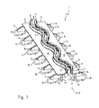
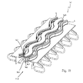
- FIG. 1 to 8 are a first and a second embodiment of the device 1, 81 according to the invention for bridging an expansion joint between two structural parts 2a, 2b shown.
- the device 1 or 81 has two profile constructions, which can each be fastened to a structural part 2a, 2b.
- Each profile construction again consists in each case in the manner of an assembly of a joint profile 4, 84 and an anchor construction 3.
- the joint profiles 4, 84 are thus fastened by means of the anchor structures 3 on the relevant component, for example a bridge girder 2a or 2b. They serve to hold one only in Fig. 7 shown Dehnbandes 2c made of rubber. This is fixed after attachment of the profile constructions to the relevant joint profiles 4, 84.
- the device for bridging an expansion joint 1 81 thus each consist of two profile constructions and a stretch band 2c.
- the joint profiles 4, 84 are wavy in the joint longitudinal direction FLR.
- the joint profiles 4, 84 arranged opposite one another on the expansion joint 2 are adapted to each other in the course. So they can interlock when the component gap or the expansion joint 2 in width decreases and the joint profiles 4, 84 approach each other.
- the joint profiles 4, 84 now assume the function of the finger plates used hitherto, so that the finger plates can be dispensed with
- the profile constructions are the same at both construction sites but mirrored or installed rotated by 180 °.
- the wavelength WL of the joint profiles 4, 84 ie the distance between two adjacent maxima in the joint longitudinal direction FLR, is approximately 500 mm. This ensures that a wavelength WL of the joint profile 4, 84 is generally narrower than the twin closure of a truck. This serves above all the sound insulation and with large gap widths the driving comfort.
- the joint profile is connected to an underlying part, i. welded.
- the amplitude A of the joint profiles 4, 84 is approximately 100 mm. Due to the waveform of the joint profiles 4, 84 can - in contrast to profile constructions with straight joint course - expansion joints 2 to a width of 100 mm easily and in particular bridge without intermediate structures. Thus, it is possible to dispense with the arrangement of otherwise customary center carriers, etc., or to reduce the number of these center carriers,
- the joint profiles 4 are made in one piece. They are made of a continuous casting or rolled section that has been bent into the undulating shape by a cold forming process.
- Each joint profile 4 is F-shaped in cross-section, wherein the retaining legs 7, 8 are formed claw-shaped for the expansion band, so that Deutschenschnmeldept 9 to the holding gifts 7, 8 are present, in which the stretch band can engage the detent.
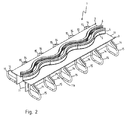
- the joint profile 84 is designed as a multipart welded construction.
- the vertical web portions 85th placed together so that they form a wave-shaped, vertical web 86.
- a wave-shaped cover plate 87 is welded, which is in one piece,
- a retaining leg 89 is welded to the vertical web 86 on the joint side 88 below the cover plate 87, which is slightly bent in the vertical direction VR upwards.
- the characteristic F-shape is formed in the cross section of the wave-shaped joint profile 84.
- the joint profiles 4, 84 of all Fig. 1 to 8 are each welded to a cross member 10 of a T-shaped anchor profile 11, especially on the so-called mounting leg 12.
- the outer edge 13 of the mounting leg 12 has a wave-shaped course and is adapted to the course of the wave-shaped web 86.
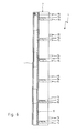
- anchor bracket 15 is provided at the T-shaped armature profile 11 at regular intervals armature plates 14 and the armature plates 14 anchor bracket 15 is provided.
- the anchor bars may consist of several interconnected, straight or curved anchor bracket elements.
- the joint profile 4, 84 can be poured into a joint edge substructure 16, which is provided in a recess 17 of the building parts 2a, 2b, as best in Fig. 7 can recognize.
- the anchor structures 3 are therefore those which serve to anchor the joint profiles 4, 84 in concrete components 2 a, 2 b.
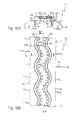
- a third embodiment of the device 91 for bridging an expansion joint 2 is shown.
- Two building parts 2a, 2b each have recesses 94.
- joint profiles 96 are arranged.
- the recesses are filled with polymer concrete 98 (PC, English: Polymer Concrete).
- the polymer MAURER Betoflex ® is preferably used.
- Each joint profile 96 has a holding portion 100 and an anchoring portion 102 forming an anchor structure.
- the holding sections 100 are essentially C-shaped and have claw-shaped legs 104, 105 for holding a stretch band 2c.
- the anchoring sections 102 extend on the sides of the holding sections 96 facing away from the expansion joint 2 in the horizontal direction HR and are executed in the shape of a wing.
- vertically extending shuttering webs 109 are arranged below the joint profiles 96 vertically extending shuttering webs 109 are arranged. How to particular in Fig. 9B can see the joint profiles 96 executed adapted to each other.
- Each shuttering land 109 is composed of two types of shuttering land portions 111, 112 having two shapes: one shuttering land portion 111 is pronounced in shape of an upside down and "T" drawn width, while another shuttering land portion 112 is bent.
- the formwork web sections 111, 112 are connected to one another.
- the formwork webs 109 are lost formwork, that is, they are not removed after the casting of the polymer concrete.
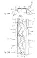
- a fourth embodiment 121 of the device for bridging an expansion joint 2 is shown.
- a cutout 124 is provided in two parts of the structure 2a, 2b separated from each other by an expansion joint 2.
- each recess 124 each have a joint profile 126 is arranged.
- the remainder of the recess 124 is filled with polymer concrete 128.
- the product MAURER Betoflex ® comes as polymer concrete used.
- the joint profiles 126 are adapted to each other in the course. Between the two joint profiles 126, the stretch band 2c is held.
- the joint profiles 126 are embodied in one piece and undulating and have holding sections 130 and anchoring sections 132 forming anchor structures.
- the holding portions 130 have substantially the same shape as the holding portions 100 of Figs. 9A and 9B on.
- the anchoring sections 132 are provided on the side of the holding sections 130 facing away from the expansion joint 2 at a lower part of the holding sections 130.
- Each of the holding portions 130 has the shape of a wing or land.
- To the holding portions 130 vertical formwork webs 134 are attached. How to get in Fig. 10B can see, the formwork webs 134 are wave-shaped in this variant.
- the formwork webs 134 may consist of a plurality of arcuate formwork web sections 136, which are joined together.
- a fifth embodiment of the device 141 for bridging an expansion joint is shown in which between two joint profiles 4, as shown in the Fig. 1-8 and the above description, a wavy intermediate structure 143 is provided in plan view.
- the intermediate structure 143 has a center girder 144, which remotely in cross-section reminiscent of a double-T-carrier with an additional central cross member, on the joint profiles 4 facing sides of the center support 144 is also provided with joint profiles 145, 146, the claw-shaped legs 147 for receiving a Dehnbandes not shown in detail exhibit.
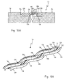
- FIG. 12A and 12B a further embodiment of the device 151 for bridging an expansion joint at maximum elongation is shown, in which the joint profiles 154 in the head region 152 have wave-shaped projections 153.
- the projections 153 are attached to the joint profiles 154, ie welded, cover plates 155 are provided. While the joint profiles 154 follow in the course of a primary shaft, the course of the projections 153 is characterized by a secondary shaft.
- the secondary wave has a smaller wavelength and amplitude than the primary wave.
- the furthest projecting projections 153 of the cover plates 155 overlap seen in the longitudinal direction of the joint FLR.
- the cover plates 155 are made of stainless steel.
- the height HD1 of the cover plates 155 is approximately 20 mm.
- the distance AD1 of the cover plates 155 measured transversely to the joint longitudinal direction FLR is at most 160 mm at each point.
- the adjacent tips 158 of opposite projections 153 are spaced at most 100 mm apart.
- FIGS. 13A and 13B show a device 161 for bridging an expansion joint according to the second solution of the problem, which is shown at maximum elongation.
- the device 161 here now has two straight joint profiles 162 for holding a stretch band 2c which at least partially seals the expansion joint.
- the joint profiles 162 can each be fastened to anchor structures 163 on the relevant structural part.
- cover plates 164 are arranged, in particular welded.
- the cover plates 164 have matched wavy projections 165.
- the contour 166 of the undulating projections 165 results again from an addition of a primary shaft and a secondary shaft.
- the wavelength and amplitude of the secondary wave are also lower than those of the primary wave.
- the cover plates 164 are made of stainless steel.
- the height HD2 of the cover plates 164 is approximately 20 mm.
- the distance AD2 of the cover plates 164 measured transversely to the joint longitudinal direction FLR is at most 160 mm at each point.
- adjacent tips 169 of opposed projections 165 are spaced a maximum of 100 mm apart.
Landscapes
- Engineering & Computer Science (AREA)
- Architecture (AREA)
- Civil Engineering (AREA)
- Structural Engineering (AREA)
- Bridges Or Land Bridges (AREA)
- Road Paving Structures (AREA)
- Building Environments (AREA)
- Orthopedics, Nursing, And Contraception (AREA)
- Prostheses (AREA)
- Joining Of Building Structures In Genera (AREA)
- Mutual Connection Of Rods And Tubes (AREA)
Priority Applications (1)
| Application Number | Priority Date | Filing Date | Title |
|---|---|---|---|
| PL10189679T PL2322719T3 (pl) | 2009-11-11 | 2010-11-02 | Urządzenia do mostkowania szczelin dylatacyjnych |
Applications Claiming Priority (1)
| Application Number | Priority Date | Filing Date | Title |
|---|---|---|---|
| DE102009052751A DE102009052751A1 (de) | 2009-11-11 | 2009-11-11 | Vorrichtungen zur Überbrückung von Dehnfugen, Profilkonstruktion und Verfahren zur Herstellung von Fugenprofilen |
Publications (3)
| Publication Number | Publication Date |
|---|---|
| EP2322719A2 true EP2322719A2 (fr) | 2011-05-18 |
| EP2322719A3 EP2322719A3 (fr) | 2012-10-03 |
| EP2322719B1 EP2322719B1 (fr) | 2015-07-29 |
Family
ID=43617876
Family Applications (1)
| Application Number | Title | Priority Date | Filing Date |
|---|---|---|---|
| EP10189679.3A Active EP2322719B1 (fr) | 2009-11-11 | 2010-11-02 | Dispositifs destinés à enjamber des joints de dilatation |
Country Status (6)
| Country | Link |
|---|---|
| EP (1) | EP2322719B1 (fr) |
| DE (2) | DE202009018663U1 (fr) |
| DK (1) | DK2322719T3 (fr) |
| HU (1) | HUE025997T2 (fr) |
| PL (1) | PL2322719T3 (fr) |
| RU (1) | RU2544186C2 (fr) |
Cited By (1)
| Publication number | Priority date | Publication date | Assignee | Title |
|---|---|---|---|---|
| GB2612176A (en) * | 2021-08-25 | 2023-04-26 | Illinois Tool Works | Joint former apparatus |
Families Citing this family (5)
| Publication number | Priority date | Publication date | Assignee | Title |
|---|---|---|---|---|
| CN102587274B (zh) * | 2012-02-27 | 2015-01-14 | 刘强 | 伸缩缝构件和桥梁伸缩缝装置和伸缩缝装置安装方法 |
| DE202013001442U1 (de) | 2013-02-15 | 2013-04-24 | Schreiber Brücken Dehntechnik GmbH | Überbrückung von Dehnfugen bei befahrbaren Bauwerken |
| AT15632U1 (de) * | 2016-11-25 | 2018-03-15 | Emsolpro Gmbh | Verladerampe |
| DE102018112634A1 (de) * | 2018-05-25 | 2019-11-28 | HSD Industriebeläge GmbH | Fugenprofil |
| DE202018102948U1 (de) | 2018-05-25 | 2018-06-12 | HSD Industriebeläge GmbH | Fugenprofil |
Citations (5)
| Publication number | Priority date | Publication date | Assignee | Title |
|---|---|---|---|---|
| DE2943872A1 (de) * | 1979-10-30 | 1981-05-14 | Motonosuke Ashiya Hyogo Arai | Dichtung fuer dehnungsfugen |
| DE3522884C1 (de) * | 1985-06-26 | 1986-10-30 | Gebr. Hennig Gmbh, 8045 Ismaning | Teleskopabdeckung |
| WO1991008345A1 (fr) * | 1989-12-02 | 1991-06-13 | Kober Ag | Dispositif pour le recouvrement et l'etanchement de joints de dilatation, en particulier dans des chaussees |
| DE19705531A1 (de) * | 1997-02-13 | 1998-08-20 | Maurer Friedrich Soehne | Vorrichtung zur Überbrückung von Dehnfugen |
| DE10108907A1 (de) * | 2001-02-23 | 2002-10-02 | Maurer Friedrich Soehne | Einprofilige Überbrückungsvorrichtung und Verfahren zur Sanierung einer solchen |
Family Cites Families (6)
| Publication number | Priority date | Publication date | Assignee | Title |
|---|---|---|---|---|
| DE1970553U (de) * | 1964-08-25 | 1967-10-19 | Margret Bahlo | Buegelhaken. |
| SU580032A1 (ru) * | 1975-11-24 | 1977-11-15 | Магнитогорский Дважды Ордена Ленина И Ордена Трудового Красного Знамени Металлургический Комбинат Им.В.И.Ленина | Способ гибки профилей с гофрами жесткости |
| SU620308A1 (ru) * | 1976-04-12 | 1978-08-25 | Магнитогорский Дважды Ордена Ленина И Ордена Трудового Красного Знамени Металлургический Комбинат Им.В.И.Ленина | Способ изготовлени гофрированных листов |
| SU1142195A1 (ru) * | 1983-06-17 | 1985-02-28 | Магнитогорский Дважды Ордена Ленина,Ордена Октябрьской Революции И Ордена Трудового Красного Знамени Металлургический Комбинат Им.В.И.Ленина | Способ производства профилей высокой жесткости |
| RU2088355C1 (ru) * | 1992-05-07 | 1997-08-27 | Евгений Николаевич Чебурахин | Способ изготовления гнутых гофрированных профилей |
| DE19637915C2 (de) * | 1996-09-17 | 2001-03-01 | Alfred Hartkorn | Einknöpfprofilanordnung für eine Fugenüberbrückungskonstruktion |
-
2009
- 2009-11-11 DE DE202009018663U patent/DE202009018663U1/de not_active Expired - Lifetime
- 2009-11-11 DE DE102009052751A patent/DE102009052751A1/de not_active Ceased
-
2010
- 2010-11-02 PL PL10189679T patent/PL2322719T3/pl unknown
- 2010-11-02 DK DK10189679.3T patent/DK2322719T3/da active
- 2010-11-02 HU HUE10189679A patent/HUE025997T2/hu unknown
- 2010-11-02 EP EP10189679.3A patent/EP2322719B1/fr active Active
- 2010-11-08 RU RU2010145216/03A patent/RU2544186C2/ru active
Patent Citations (5)
| Publication number | Priority date | Publication date | Assignee | Title |
|---|---|---|---|---|
| DE2943872A1 (de) * | 1979-10-30 | 1981-05-14 | Motonosuke Ashiya Hyogo Arai | Dichtung fuer dehnungsfugen |
| DE3522884C1 (de) * | 1985-06-26 | 1986-10-30 | Gebr. Hennig Gmbh, 8045 Ismaning | Teleskopabdeckung |
| WO1991008345A1 (fr) * | 1989-12-02 | 1991-06-13 | Kober Ag | Dispositif pour le recouvrement et l'etanchement de joints de dilatation, en particulier dans des chaussees |
| DE19705531A1 (de) * | 1997-02-13 | 1998-08-20 | Maurer Friedrich Soehne | Vorrichtung zur Überbrückung von Dehnfugen |
| DE10108907A1 (de) * | 2001-02-23 | 2002-10-02 | Maurer Friedrich Soehne | Einprofilige Überbrückungsvorrichtung und Verfahren zur Sanierung einer solchen |
Cited By (2)
| Publication number | Priority date | Publication date | Assignee | Title |
|---|---|---|---|---|
| GB2612176A (en) * | 2021-08-25 | 2023-04-26 | Illinois Tool Works | Joint former apparatus |
| GB2612176B (en) * | 2021-08-25 | 2023-12-06 | Illinois Tool Works | Joint former apparatus |
Also Published As
| Publication number | Publication date |
|---|---|
| RU2010145216A (ru) | 2012-05-20 |
| RU2544186C2 (ru) | 2015-03-10 |
| DK2322719T3 (da) | 2015-10-26 |
| PL2322719T3 (pl) | 2016-02-29 |
| DE102009052751A1 (de) | 2011-05-26 |
| DE202009018663U1 (de) | 2012-07-16 |
| HUE025997T2 (hu) | 2016-05-30 |
| EP2322719A3 (fr) | 2012-10-03 |
| EP2322719B1 (fr) | 2015-07-29 |
Similar Documents
| Publication | Publication Date | Title |
|---|---|---|
| EP1763613B1 (fr) | Dispositif de pontage | |
| EP2322719B1 (fr) | Dispositifs destinés à enjamber des joints de dilatation | |
| DE3222409C2 (fr) | ||
| EP2925932B1 (fr) | Dispositif de pontage pour joints de dilatation | |
| EP1927699B1 (fr) | Muret de séparation du trafic | |
| EP3436638B1 (fr) | Structure de transition servant au pontage d'un joint de construction | |
| EP1124014B1 (fr) | Element de paroi en béton pour barrière de sécurité routière | |
| EP1327026B1 (fr) | Systeme de plaques dentees destine a un dispositif de pontage de joints de dilatation | |
| EP1771626A1 (fr) | Dispositif de pontage | |
| DE19851877A1 (de) | Verbindungselement für Spundbohlen | |
| DE102007063511B4 (de) | Schutzeinrichtung an Verkehrswegen | |
| DE2339638B2 (de) | Als Bewehrung für eine Betonverbunddecke dienende Schalungsplatte aus Blech | |
| WO2000028157A1 (fr) | Element de liaison destine a des palplanches metalliques | |
| DE102012112023B4 (de) | Fußbodenbauschalungselement | |
| DE202007017342U1 (de) | Bausatz für Spundwände | |
| DE202006007405U1 (de) | Schubbewehrungselement | |
| DE4026515C1 (en) | Expansion joint for roadway - has edging bars and inner bars connected by stretched elastic strip | |
| WO2004081286A1 (fr) | Coeur de croisement de rails a gorge | |
| DE102004019745A1 (de) | Abdichtung für Bauwerksfuge | |
| WO1991008345A1 (fr) | Dispositif pour le recouvrement et l'etanchement de joints de dilatation, en particulier dans des chaussees | |
| DE2136842A1 (de) | Vorrichtung zum ueberbruecken von dehnungsfugen in verkehrswegen oder anderen bauwerken | |
| EP2080841A2 (fr) | Elément de pose de dalles en console | |
| DE2906085C2 (fr) | ||
| EP0773333A1 (fr) | Armature pour maçonnerie | |
| WO2014086808A1 (fr) | Châssis de caniveau |
Legal Events
| Date | Code | Title | Description |
|---|---|---|---|
| PUAI | Public reference made under article 153(3) epc to a published international application that has entered the european phase |
Free format text: ORIGINAL CODE: 0009012 |
|
| AK | Designated contracting states |
Kind code of ref document: A2 Designated state(s): AL AT BE BG CH CY CZ DE DK EE ES FI FR GB GR HR HU IE IS IT LI LT LU LV MC MK MT NL NO PL PT RO RS SE SI SK SM TR |
|
| AX | Request for extension of the european patent |
Extension state: BA ME |
|
| PUAL | Search report despatched |
Free format text: ORIGINAL CODE: 0009013 |
|
| AK | Designated contracting states |
Kind code of ref document: A3 Designated state(s): AL AT BE BG CH CY CZ DE DK EE ES FI FR GB GR HR HU IE IS IT LI LT LU LV MC MK MT NL NO PL PT RO RS SE SI SK SM TR |
|
| AX | Request for extension of the european patent |
Extension state: BA ME |
|
| RIC1 | Information provided on ipc code assigned before grant |
Ipc: E01D 19/06 20060101AFI20120827BHEP |
|
| 17P | Request for examination filed |
Effective date: 20130403 |
|
| 17Q | First examination report despatched |
Effective date: 20130430 |
|
| GRAP | Despatch of communication of intention to grant a patent |
Free format text: ORIGINAL CODE: EPIDOSNIGR1 |
|
| INTG | Intention to grant announced |
Effective date: 20150223 |
|
| GRAS | Grant fee paid |
Free format text: ORIGINAL CODE: EPIDOSNIGR3 |
|
| GRAA | (expected) grant |
Free format text: ORIGINAL CODE: 0009210 |
|
| AK | Designated contracting states |
Kind code of ref document: B1 Designated state(s): AL AT BE BG CH CY CZ DE DK EE ES FI FR GB GR HR HU IE IS IT LI LT LU LV MC MK MT NL NO PL PT RO RS SE SI SK SM TR |
|
| REG | Reference to a national code |
Ref country code: GB Ref legal event code: FG4D Free format text: NOT ENGLISH |
|
| REG | Reference to a national code |
Ref country code: CH Ref legal event code: EP |
|
| REG | Reference to a national code |
Ref country code: AT Ref legal event code: REF Ref document number: 739387 Country of ref document: AT Kind code of ref document: T Effective date: 20150815 |
|
| REG | Reference to a national code |
Ref country code: IE Ref legal event code: FG4D Free format text: LANGUAGE OF EP DOCUMENT: GERMAN |
|
| REG | Reference to a national code |
Ref country code: DE Ref legal event code: R096 Ref document number: 502010009938 Country of ref document: DE |
|
| REG | Reference to a national code |
Ref country code: RO Ref legal event code: EPE |
|
| REG | Reference to a national code |
Ref country code: DK Ref legal event code: T3 Effective date: 20151020 |
|
| REG | Reference to a national code |
Ref country code: CH Ref legal event code: NV Representative=s name: TROESCH SCHEIDEGGER WERNER AG, CH |
|
| REG | Reference to a national code |
Ref country code: SE Ref legal event code: TRGR Ref country code: FR Ref legal event code: PLFP Year of fee payment: 6 |
|
| REG | Reference to a national code |
Ref country code: LT Ref legal event code: MG4D |
|
| REG | Reference to a national code |
Ref country code: NL Ref legal event code: FP |
|
| REG | Reference to a national code |
Ref country code: NO Ref legal event code: T2 Effective date: 20150729 |
|
| PG25 | Lapsed in a contracting state [announced via postgrant information from national office to epo] |
Ref country code: GR Free format text: LAPSE BECAUSE OF FAILURE TO SUBMIT A TRANSLATION OF THE DESCRIPTION OR TO PAY THE FEE WITHIN THE PRESCRIBED TIME-LIMIT Effective date: 20151030 Ref country code: LV Free format text: LAPSE BECAUSE OF FAILURE TO SUBMIT A TRANSLATION OF THE DESCRIPTION OR TO PAY THE FEE WITHIN THE PRESCRIBED TIME-LIMIT Effective date: 20150729 Ref country code: LT Free format text: LAPSE BECAUSE OF FAILURE TO SUBMIT A TRANSLATION OF THE DESCRIPTION OR TO PAY THE FEE WITHIN THE PRESCRIBED TIME-LIMIT Effective date: 20150729 |
|
| PGFP | Annual fee paid to national office [announced via postgrant information from national office to epo] |
Ref country code: IE Payment date: 20151102 Year of fee payment: 6 |
|
| PG25 | Lapsed in a contracting state [announced via postgrant information from national office to epo] |
Ref country code: ES Free format text: LAPSE BECAUSE OF FAILURE TO SUBMIT A TRANSLATION OF THE DESCRIPTION OR TO PAY THE FEE WITHIN THE PRESCRIBED TIME-LIMIT Effective date: 20150729 Ref country code: PT Free format text: LAPSE BECAUSE OF FAILURE TO SUBMIT A TRANSLATION OF THE DESCRIPTION OR TO PAY THE FEE WITHIN THE PRESCRIBED TIME-LIMIT Effective date: 20151130 Ref country code: HR Free format text: LAPSE BECAUSE OF FAILURE TO SUBMIT A TRANSLATION OF THE DESCRIPTION OR TO PAY THE FEE WITHIN THE PRESCRIBED TIME-LIMIT Effective date: 20150729 Ref country code: IS Free format text: LAPSE BECAUSE OF FAILURE TO SUBMIT A TRANSLATION OF THE DESCRIPTION OR TO PAY THE FEE WITHIN THE PRESCRIBED TIME-LIMIT Effective date: 20151129 Ref country code: RS Free format text: LAPSE BECAUSE OF FAILURE TO SUBMIT A TRANSLATION OF THE DESCRIPTION OR TO PAY THE FEE WITHIN THE PRESCRIBED TIME-LIMIT Effective date: 20150729 |
|
| PG25 | Lapsed in a contracting state [announced via postgrant information from national office to epo] |
Ref country code: SK Free format text: LAPSE BECAUSE OF FAILURE TO SUBMIT A TRANSLATION OF THE DESCRIPTION OR TO PAY THE FEE WITHIN THE PRESCRIBED TIME-LIMIT Effective date: 20150729 Ref country code: EE Free format text: LAPSE BECAUSE OF FAILURE TO SUBMIT A TRANSLATION OF THE DESCRIPTION OR TO PAY THE FEE WITHIN THE PRESCRIBED TIME-LIMIT Effective date: 20150729 |
|
| REG | Reference to a national code |
Ref country code: DE Ref legal event code: R097 Ref document number: 502010009938 Country of ref document: DE |
|
| REG | Reference to a national code |
Ref country code: HU Ref legal event code: AG4A Ref document number: E025997 Country of ref document: HU |
|
| PLBE | No opposition filed within time limit |
Free format text: ORIGINAL CODE: 0009261 |
|
| STAA | Information on the status of an ep patent application or granted ep patent |
Free format text: STATUS: NO OPPOSITION FILED WITHIN TIME LIMIT |
|
| PG25 | Lapsed in a contracting state [announced via postgrant information from national office to epo] |
Ref country code: LU Free format text: LAPSE BECAUSE OF FAILURE TO SUBMIT A TRANSLATION OF THE DESCRIPTION OR TO PAY THE FEE WITHIN THE PRESCRIBED TIME-LIMIT Effective date: 20151102 Ref country code: MC Free format text: LAPSE BECAUSE OF FAILURE TO SUBMIT A TRANSLATION OF THE DESCRIPTION OR TO PAY THE FEE WITHIN THE PRESCRIBED TIME-LIMIT Effective date: 20150729 |
|
| 26N | No opposition filed |
Effective date: 20160502 |
|
| PG25 | Lapsed in a contracting state [announced via postgrant information from national office to epo] |
Ref country code: SI Free format text: LAPSE BECAUSE OF FAILURE TO SUBMIT A TRANSLATION OF THE DESCRIPTION OR TO PAY THE FEE WITHIN THE PRESCRIBED TIME-LIMIT Effective date: 20150729 |
|
| REG | Reference to a national code |
Ref country code: FR Ref legal event code: PLFP Year of fee payment: 7 |
|
| PG25 | Lapsed in a contracting state [announced via postgrant information from national office to epo] |
Ref country code: BG Free format text: LAPSE BECAUSE OF FAILURE TO SUBMIT A TRANSLATION OF THE DESCRIPTION OR TO PAY THE FEE WITHIN THE PRESCRIBED TIME-LIMIT Effective date: 20150729 Ref country code: SM Free format text: LAPSE BECAUSE OF FAILURE TO SUBMIT A TRANSLATION OF THE DESCRIPTION OR TO PAY THE FEE WITHIN THE PRESCRIBED TIME-LIMIT Effective date: 20150729 |
|
| PG25 | Lapsed in a contracting state [announced via postgrant information from national office to epo] |
Ref country code: CY Free format text: LAPSE BECAUSE OF FAILURE TO SUBMIT A TRANSLATION OF THE DESCRIPTION OR TO PAY THE FEE WITHIN THE PRESCRIBED TIME-LIMIT Effective date: 20150729 |
|
| REG | Reference to a national code |
Ref country code: IE Ref legal event code: MM4A |
|
| PG25 | Lapsed in a contracting state [announced via postgrant information from national office to epo] |
Ref country code: TR Free format text: LAPSE BECAUSE OF FAILURE TO SUBMIT A TRANSLATION OF THE DESCRIPTION OR TO PAY THE FEE WITHIN THE PRESCRIBED TIME-LIMIT Effective date: 20150729 Ref country code: MT Free format text: LAPSE BECAUSE OF FAILURE TO SUBMIT A TRANSLATION OF THE DESCRIPTION OR TO PAY THE FEE WITHIN THE PRESCRIBED TIME-LIMIT Effective date: 20150729 |
|
| REG | Reference to a national code |
Ref country code: FR Ref legal event code: PLFP Year of fee payment: 8 |
|
| PG25 | Lapsed in a contracting state [announced via postgrant information from national office to epo] |
Ref country code: IE Free format text: LAPSE BECAUSE OF NON-PAYMENT OF DUE FEES Effective date: 20161102 |
|
| PG25 | Lapsed in a contracting state [announced via postgrant information from national office to epo] |
Ref country code: MK Free format text: LAPSE BECAUSE OF FAILURE TO SUBMIT A TRANSLATION OF THE DESCRIPTION OR TO PAY THE FEE WITHIN THE PRESCRIBED TIME-LIMIT Effective date: 20150729 |
|
| PG25 | Lapsed in a contracting state [announced via postgrant information from national office to epo] |
Ref country code: AL Free format text: LAPSE BECAUSE OF FAILURE TO SUBMIT A TRANSLATION OF THE DESCRIPTION OR TO PAY THE FEE WITHIN THE PRESCRIBED TIME-LIMIT Effective date: 20150729 |
|
| PGFP | Annual fee paid to national office [announced via postgrant information from national office to epo] |
Ref country code: NL Payment date: 20231122 Year of fee payment: 14 |
|
| PGFP | Annual fee paid to national office [announced via postgrant information from national office to epo] |
Ref country code: GB Payment date: 20231123 Year of fee payment: 14 |
|
| PGFP | Annual fee paid to national office [announced via postgrant information from national office to epo] |
Ref country code: SE Payment date: 20231123 Year of fee payment: 14 Ref country code: RO Payment date: 20231031 Year of fee payment: 14 Ref country code: NO Payment date: 20231121 Year of fee payment: 14 Ref country code: IT Payment date: 20231130 Year of fee payment: 14 Ref country code: HU Payment date: 20231027 Year of fee payment: 14 Ref country code: FR Payment date: 20231124 Year of fee payment: 14 Ref country code: FI Payment date: 20231120 Year of fee payment: 14 Ref country code: DK Payment date: 20231122 Year of fee payment: 14 Ref country code: DE Payment date: 20231120 Year of fee payment: 14 Ref country code: CZ Payment date: 20231023 Year of fee payment: 14 Ref country code: CH Payment date: 20231201 Year of fee payment: 14 Ref country code: AT Payment date: 20231117 Year of fee payment: 14 |
|
| PGFP | Annual fee paid to national office [announced via postgrant information from national office to epo] |
Ref country code: PL Payment date: 20231023 Year of fee payment: 14 Ref country code: BE Payment date: 20231121 Year of fee payment: 14 |