EP3536883B1 - Fahrzeuginnengriffvorrichtung - Google Patents
Fahrzeuginnengriffvorrichtung Download PDFInfo
- Publication number
- EP3536883B1 EP3536883B1 EP17866785.3A EP17866785A EP3536883B1 EP 3536883 B1 EP3536883 B1 EP 3536883B1 EP 17866785 A EP17866785 A EP 17866785A EP 3536883 B1 EP3536883 B1 EP 3536883B1
- Authority
- EP
- European Patent Office
- Prior art keywords
- cable
- connecting body
- handle
- recess
- unit
- Prior art date
- Legal status (The legal status is an assumption and is not a legal conclusion. Google has not performed a legal analysis and makes no representation as to the accuracy of the status listed.)
- Active
Links
Images


Classifications
-
- E—FIXED CONSTRUCTIONS
- E05—LOCKS; KEYS; WINDOW OR DOOR FITTINGS; SAFES
- E05B—LOCKS; ACCESSORIES THEREFOR; HANDCUFFS
- E05B79/00—Mounting or connecting vehicle locks or parts thereof
- E05B79/10—Connections between movable lock parts
- E05B79/20—Connections between movable lock parts using flexible connections, e.g. Bowden cables
-
- B—PERFORMING OPERATIONS; TRANSPORTING
- B60—VEHICLES IN GENERAL
- B60J—WINDOWS, WINDSCREENS, NON-FIXED ROOFS, DOORS, OR SIMILAR DEVICES FOR VEHICLES; REMOVABLE EXTERNAL PROTECTIVE COVERINGS SPECIALLY ADAPTED FOR VEHICLES
- B60J5/00—Doors
- B60J5/04—Doors arranged at the vehicle sides
-
- E—FIXED CONSTRUCTIONS
- E05—LOCKS; KEYS; WINDOW OR DOOR FITTINGS; SAFES
- E05B—LOCKS; ACCESSORIES THEREFOR; HANDCUFFS
- E05B79/00—Mounting or connecting vehicle locks or parts thereof
- E05B79/02—Mounting of vehicle locks or parts thereof
- E05B79/06—Mounting of handles, e.g. to the wing or to the lock
-
- E—FIXED CONSTRUCTIONS
- E05—LOCKS; KEYS; WINDOW OR DOOR FITTINGS; SAFES
- E05B—LOCKS; ACCESSORIES THEREFOR; HANDCUFFS
- E05B79/00—Mounting or connecting vehicle locks or parts thereof
- E05B79/02—Mounting of vehicle locks or parts thereof
- E05B79/08—Mounting of individual lock elements in the lock, e.g. levers
-
- E—FIXED CONSTRUCTIONS
- E05—LOCKS; KEYS; WINDOW OR DOOR FITTINGS; SAFES
- E05B—LOCKS; ACCESSORIES THEREFOR; HANDCUFFS
- E05B79/00—Mounting or connecting vehicle locks or parts thereof
- E05B79/10—Connections between movable lock parts
- E05B79/22—Operative connections between handles, sill buttons or lock knobs and the lock unit
-
- E—FIXED CONSTRUCTIONS
- E05—LOCKS; KEYS; WINDOW OR DOOR FITTINGS; SAFES
- E05B—LOCKS; ACCESSORIES THEREFOR; HANDCUFFS
- E05B85/00—Details of vehicle locks not provided for in groups E05B77/00 - E05B83/00
- E05B85/10—Handles
- E05B85/12—Inner door handles
-
- E—FIXED CONSTRUCTIONS
- E05—LOCKS; KEYS; WINDOW OR DOOR FITTINGS; SAFES
- E05B—LOCKS; ACCESSORIES THEREFOR; HANDCUFFS
- E05B85/00—Details of vehicle locks not provided for in groups E05B77/00 - E05B83/00
- E05B85/10—Handles
- E05B85/12—Inner door handles
- E05B85/13—Inner door handles with a locking knob forming part of the inside door handle unit
-
- E—FIXED CONSTRUCTIONS
- E05—LOCKS; KEYS; WINDOW OR DOOR FITTINGS; SAFES
- E05Y—INDEXING SCHEME ASSOCIATED WITH SUBCLASSES E05D AND E05F, RELATING TO CONSTRUCTION ELEMENTS, ELECTRIC CONTROL, POWER SUPPLY, POWER SIGNAL OR TRANSMISSION, USER INTERFACES, MOUNTING OR COUPLING, DETAILS, ACCESSORIES, AUXILIARY OPERATIONS NOT OTHERWISE PROVIDED FOR, APPLICATION THEREOF
- E05Y2201/00—Constructional elements; Accessories therefor
- E05Y2201/60—Suspension or transmission members; Accessories therefor
- E05Y2201/622—Suspension or transmission members elements
- E05Y2201/676—Transmission of human force
- E05Y2201/68—Handles, cranks
-
- E—FIXED CONSTRUCTIONS
- E05—LOCKS; KEYS; WINDOW OR DOOR FITTINGS; SAFES
- E05Y—INDEXING SCHEME ASSOCIATED WITH SUBCLASSES E05D AND E05F, RELATING TO CONSTRUCTION ELEMENTS, ELECTRIC CONTROL, POWER SUPPLY, POWER SIGNAL OR TRANSMISSION, USER INTERFACES, MOUNTING OR COUPLING, DETAILS, ACCESSORIES, AUXILIARY OPERATIONS NOT OTHERWISE PROVIDED FOR, APPLICATION THEREOF
- E05Y2900/00—Application of doors, windows, wings or fittings thereof
- E05Y2900/50—Application of doors, windows, wings or fittings thereof for vehicles
- E05Y2900/53—Type of wing
- E05Y2900/531—Doors
-
- F—MECHANICAL ENGINEERING; LIGHTING; HEATING; WEAPONS; BLASTING
- F16—ENGINEERING ELEMENTS AND UNITS; GENERAL MEASURES FOR PRODUCING AND MAINTAINING EFFECTIVE FUNCTIONING OF MACHINES OR INSTALLATIONS; THERMAL INSULATION IN GENERAL
- F16C—SHAFTS; FLEXIBLE SHAFTS; ELEMENTS OR CRANKSHAFT MECHANISMS; ROTARY BODIES OTHER THAN GEARING ELEMENTS; BEARINGS
- F16C1/00—Flexible shafts; Mechanical means for transmitting movement in a flexible sheathing
- F16C1/10—Means for transmitting linear movement in a flexible sheathing, e.g. "Bowden-mechanisms"
- F16C1/12—Arrangements for transmitting movement to or from the flexible member
- F16C1/14—Construction of the end-piece of the flexible member; Attachment thereof to the flexible member
- F16C1/145—Attachment of the end-piece to the flexible member
-
- F—MECHANICAL ENGINEERING; LIGHTING; HEATING; WEAPONS; BLASTING
- F16—ENGINEERING ELEMENTS AND UNITS; GENERAL MEASURES FOR PRODUCING AND MAINTAINING EFFECTIVE FUNCTIONING OF MACHINES OR INSTALLATIONS; THERMAL INSULATION IN GENERAL
- F16C—SHAFTS; FLEXIBLE SHAFTS; ELEMENTS OR CRANKSHAFT MECHANISMS; ROTARY BODIES OTHER THAN GEARING ELEMENTS; BEARINGS
- F16C2350/00—Machines or articles related to building
- F16C2350/52—Locks, e.g. cables to actuate door locks
Definitions
- the present invention relates to an inside handle device for vehicle.
- Patent Literature 1 discloses an inside handle device for vehicle formed by connecting a handle unit incorporating an operation handle and a cable unit holding a cable device.
- a recess (connecting recess) formed in a leg of the operation handle is engaged with the straight rod-like connecting body, and thereafter, the cable device is driven by operating the operation handle.
- a further vehicle inside handle device is known from JP 2015 206234 A .
- the connecting body is formed of a solid rotating body having a straight line intersecting an axis of the inner cable as a rotation axis, and has a shape protruding laterally from the axis of the inner cable and having a diameter gradually decreasing from a center toward both ends in a protruding direction.
- the connecting recess includes a contact portion to both side wall portions of the connecting body sandwiching a maximum diameter portion of the connecting body.
- the inside handle device is formed by connecting a cable unit 8 to which an operating force transmission cable 7 is connected and a handle unit 4 to which an operation handle 3 is connected; in a state in which both are connected to each other, a connecting recess 2 of the operation handle 3 is locked to a connecting body 9 formed at a tip end of the operating force transmission cable 7; and a latch device is remotely operated by operating the operation handle 3 via the operating force transmission cable 7.
- the connecting body 9 is formed as a shaft-shaped rotating body having a rotation axis intersecting an axis of an inner cable 6 as the rotation center, and having a diameter maximum at a center and gradually decreasing toward both ends in a rotation axis direction.
- the connecting recess 2 on the operation handle 3 side includes a contact portion 10 in contact with both side wall portions of the connecting body 9 sandwiching a maximum diameter portion of the connecting body 9, and a force toward the maximum diameter portion is generated by the contact portion 10 of the connecting recess 2 to the rotating body in a state in which the connecting recess 2 is locked to the connecting body 9.
- the connecting body 9 is always located at the center of the connecting recess 2, and operation of the connecting body 9 does not become difficult due to abutment of both ends of the connecting body 9 against a support of the connecting body 9, movement in an oblique posture, or the like.
- the connecting recess 2 only needs to be configured to contact the connecting body 9 in a linear shape or in a string shape of a prescribed width, if the contact portion 10 of the connecting recess 2 is formed by a curvature surface that matches the curvature of an outer peripheral wall surface of the connecting body 9 and contacts an entire surface of a corresponding portion of the connecting body 9, a wall surface of the connecting recess 2 is in contact a peripheral wall of the connecting body 9 substantially over the entire surface, so that the connecting body 9 has higher followability to the connecting recess 2.
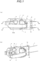
- An inside handle device is formed by connecting a cable unit 8 to an inside surface of a handle unit 4.
- a left side in FIG. 1(a) is referred to as "front”
- a front side in FIG. 1(a) is referred to as “outside”
- a rear side in FIG. 1(a) is referred to as "inside”.
- the operation handle 3 includes a handhold portion 3a and an operation leg portion 3b, and a connecting recess 2 is formed at a free end of the operation leg 3b to lock a connecting body 9 described later.
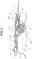
- connecting body guide recesses 17 are formed between guide walls 16 protruding in the outside direction and opposing one another. Two sets of the connecting body guide recesses 17 are formed corresponding to the operation handle 3 and the lock knob 11 of the handle unit 4 in a state in which the cable unit 8 is connected to the handle unit 4.
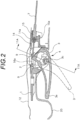
- each operating force transmission cable 7, whose one end is held on the cable cover 14 as described above, is connected in advance to the latch device 18 fixed to the door.
- the operating force transmission cable 7 corresponding to the operation handle 3 shown in the lower part is connected to a latch operation portion 18a of the latch device 18, and the operating force transmission cable 7 corresponding to the lock knob 11 shown in the upper part is connected to a lock operation portion 18b of the latch device 18.
- the lock operation portion 18b is held in an unlocked state, and when an input to the latch operation portion 18a is given, a latch release operation is performed, the lock operation portion 18b transitions to a locked state, and afterward, latch release operation via operation to the latch operation portion 18a is prohibited.
- the lock knob 11 whose rotational position is not regulated by the handle unit 4 alone, is guided by the drive protrusion and the drive piece 17a to a fitting position with the connecting body 9 held at a position that is uniquely determined by the state of the lock operation portion 18b.
- the second locking portion 13 of the cable unit 8 is eventually locked elastically to the locking opening 1b of the handle base 1 to complete the connection operation of both.
- the locking opening 1b is disposed at a position visible from the surface of the handle unit 4, and as shown in FIG. 1(b) and FIG. 8(b) , since the surface of the second locking portion 13 is exposed from the locking opening 1b to the surface in the connected state, incomplete locking state can be detected only by viewing the exposure state, and detachment of the cable unit 8 due to locking failure can be completely prevented.
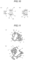
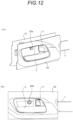
- the connecting body 9 is a barrel-shaped solid rotating body formed by using an arc as a generating line and rotating the arc around a rotation axis (CR) deviated from a center of the arc on a surface to which an arc belongs, which has a thick central portion and has a diameter gradually decreasing toward both ends, and is formed by arranging the guide projections 9a on the rotation axis (CR).
- the connecting body 9 moves following the connecting recess 2 in a moving direction of the connecting recess 2, and thus moves completely following the moving direction of the connecting recess 2 without moving obliquely, which prevents occurrence of a stroke loss, or loss of the operating force due to contact of the end surfaces of the connecting body 9 with the guide walls 16 supporting the connecting body 9.
Landscapes
- Engineering & Computer Science (AREA)
- Mechanical Engineering (AREA)
- Lock And Its Accessories (AREA)
Claims (3)
- Fahrzeuginnenhandgriffvorrichtung, welche aufweist:eine Griffeinheit (4), bei der ein mit einer Verbindungsaussparung (2) versehener Betätigungsgriff rotierbar mit einer Griffbasis (1) verbunden ist, sowie eine Kabeleinheit (8), die mit der Griffeinheit (4) verbunden ist und dabei ein Ende eines Betätigungskraftübertragungskabels (7), in dem ein Innenkabel (6) beweglich in ein Außenkabel (5) eingeführt ist, hält,wobei in einem Zustand, in dem die Griffeinheit (4) mit der Kabeleinheit (8) verbunden ist, die Verbindungsaussparung (2) fest mit einem an einem äußersten Ende des Innenkabels (6) ausgebildeten Verbindungskörper (9) verbunden ist,wobei der Verbindungskörper (9) ausgebildet ist als massiver Rotationskörper, der eine eine Achse des Innenkabels (6) schneidende Gerade als Rotationsachse aufweist und der eine Form hat, welche seitlich von der Achse des Innenkabels (6) aus hervorragt und einen Durchmesser aufweist, der von einem Mittelpunkt allmählich in Richtung der zwei Enden in einer Hervorragerichtung abnimmt, undwobei die Verbindungsaussparung (2) einen Kontaktbereich (10) aufweist, der im Kontakt mit den zwei seitlichen Wandbereichen des Verbindungskörpers (9),einen einen maximalen Durchmesser aufweisenden Bereich des Verbindungskörpers (9) sandwichartig einklemmt,dadurch gekennzeichnet, dassin einem Zustand, in dem die Verbindungsaussparung (2) fest mit dem Verbindungskörper (9) verbunden ist, durch den Kontaktbereich (10) der Verbindungsaussparung (2) eine Kraft in Richtung des einen maximalen Durchmesser aufweisenden Bereichs auf den Rotationskörper ausgeübt wird.
- Fahrzeuginnenhandgriffvorrichtung nach Anspruch 1,
wobei der Verbindungskörper (9) in einer konvexen Tonnenform ausgebildet ist. - Fahrzeuginnenhandgriffvorrichtung nach Anspruch 1 oder 2,wobei der Kontaktbereich (10) der Verbindungsaussparung (2) eine Krümmungsfläche aufweist, die einer Krümmung einer äußeren Wandfläche des Verbindungskörpers (9) entspricht, undwobei der Kontaktbereich (10) eine gesamte Fläche eines entsprechenden Bereichs des Verbindungskörpers (9) kontaktiert.
Priority Applications (1)
| Application Number | Priority Date | Filing Date | Title |
|---|---|---|---|
| EP24177723.4A EP4403784A3 (de) | 2016-11-01 | 2017-11-01 | Fahrzeuginnengriffvorrichtung |
Applications Claiming Priority (2)
| Application Number | Priority Date | Filing Date | Title |
|---|---|---|---|
| JP2016214078A JP6806528B2 (ja) | 2016-11-01 | 2016-11-01 | 車両のインサイドハンドル装置 |
| PCT/JP2017/039636 WO2018084217A1 (ja) | 2016-11-01 | 2017-11-01 | 車両のインサイドハンドル装置 |
Related Child Applications (2)
| Application Number | Title | Priority Date | Filing Date |
|---|---|---|---|
| EP24177723.4A Division EP4403784A3 (de) | 2016-11-01 | 2017-11-01 | Fahrzeuginnengriffvorrichtung |
| EP24177723.4A Division-Into EP4403784A3 (de) | 2016-11-01 | 2017-11-01 | Fahrzeuginnengriffvorrichtung |
Publications (3)
| Publication Number | Publication Date |
|---|---|
| EP3536883A1 EP3536883A1 (de) | 2019-09-11 |
| EP3536883A4 EP3536883A4 (de) | 2020-07-01 |
| EP3536883B1 true EP3536883B1 (de) | 2024-07-03 |
Family
ID=62076741
Family Applications (2)
| Application Number | Title | Priority Date | Filing Date |
|---|---|---|---|
| EP24177723.4A Withdrawn EP4403784A3 (de) | 2016-11-01 | 2017-11-01 | Fahrzeuginnengriffvorrichtung |
| EP17866785.3A Active EP3536883B1 (de) | 2016-11-01 | 2017-11-01 | Fahrzeuginnengriffvorrichtung |
Family Applications Before (1)
| Application Number | Title | Priority Date | Filing Date |
|---|---|---|---|
| EP24177723.4A Withdrawn EP4403784A3 (de) | 2016-11-01 | 2017-11-01 | Fahrzeuginnengriffvorrichtung |
Country Status (5)
| Country | Link |
|---|---|
| US (1) | US10968666B2 (de) |
| EP (2) | EP4403784A3 (de) |
| JP (1) | JP6806528B2 (de) |
| CN (2) | CN113719203A (de) |
| WO (1) | WO2018084217A1 (de) |
Families Citing this family (3)
| Publication number | Priority date | Publication date | Assignee | Title |
|---|---|---|---|---|
| JP6938132B2 (ja) * | 2016-11-07 | 2021-09-22 | 株式会社アルファ | 車両のハンドル装置 |
| EP3812544A4 (de) * | 2018-06-15 | 2022-02-23 | Alpha Corporation | Lenkradvorrichtung für fahrzeug und drehbetätigungsklammer |
| JP7313196B2 (ja) * | 2018-06-15 | 2023-07-24 | 株式会社アルファ | 車両のハンドル装置及び回転操作クリップ |
Family Cites Families (13)
| Publication number | Priority date | Publication date | Assignee | Title |
|---|---|---|---|---|
| US5884434A (en) * | 1998-06-12 | 1999-03-23 | General Motors Corporation | Door handle to latch rod connection |
| JP4213095B2 (ja) * | 2004-08-24 | 2009-01-21 | 本田技研工業株式会社 | フードリリースレバー取付構造 |
| DE102007057866B4 (de) | 2007-08-01 | 2014-07-03 | Johnson Controls Interiors Gmbh & Co. Kg | Türmodul für Fahrzeugtür und Montageverfahren |
| JP5007479B2 (ja) * | 2010-04-22 | 2012-08-22 | 三井金属アクト株式会社 | 車両用インサイドハンドル装置 |
| JP5752913B2 (ja) * | 2010-10-15 | 2015-07-22 | 株式会社アルファ | 車両のドアハンドル装置 |
| US8864193B2 (en) * | 2011-08-10 | 2014-10-21 | Honda Motor Co., Ltd. | Vehicle door inner handle cable connection |
| US9022438B2 (en) * | 2012-09-14 | 2015-05-05 | Honda Motor Co., Ltd. | Cap assembly for vehicle |
| JP5966813B2 (ja) * | 2012-09-24 | 2016-08-10 | アイシン精機株式会社 | 車両用ドアロック装置 |
| JP6131103B2 (ja) | 2013-05-24 | 2017-05-17 | 株式会社アルファ | 車両用ハンドル装置 |
| JP6368951B2 (ja) * | 2014-03-13 | 2018-08-08 | 三井金属アクト株式会社 | 車両用ドアラッチ装置 |
| JP6306415B2 (ja) * | 2014-04-22 | 2018-04-04 | 株式会社アルファ | 車両のハンドル装置 |
| JP6174209B2 (ja) | 2016-08-16 | 2017-08-02 | 東芝三菱電機産業システム株式会社 | 無停電電源装置 |
| JP7017941B2 (ja) * | 2018-01-31 | 2022-02-09 | 株式会社アルファ | インサイドハンドル装置 |
-
2016
- 2016-11-01 JP JP2016214078A patent/JP6806528B2/ja active Active
-
2017
- 2017-11-01 CN CN202110418511.5A patent/CN113719203A/zh active Pending
- 2017-11-01 EP EP24177723.4A patent/EP4403784A3/de not_active Withdrawn
- 2017-11-01 EP EP17866785.3A patent/EP3536883B1/de active Active
- 2017-11-01 CN CN201780066106.3A patent/CN109863279B/zh active Active
- 2017-11-01 WO PCT/JP2017/039636 patent/WO2018084217A1/ja not_active Ceased
-
2019
- 2019-04-24 US US16/393,443 patent/US10968666B2/en active Active
Also Published As
| Publication number | Publication date |
|---|---|
| EP4403784A3 (de) | 2024-10-23 |
| JP6806528B2 (ja) | 2021-01-06 |
| US20190249464A1 (en) | 2019-08-15 |
| EP4403784A2 (de) | 2024-07-24 |
| JP2018071244A (ja) | 2018-05-10 |
| CN109863279B (zh) | 2021-05-07 |
| WO2018084217A1 (ja) | 2018-05-11 |
| EP3536883A1 (de) | 2019-09-11 |
| EP3536883A4 (de) | 2020-07-01 |
| CN113719203A (zh) | 2021-11-30 |
| US10968666B2 (en) | 2021-04-06 |
| CN109863279A (zh) | 2019-06-07 |
Similar Documents
| Publication | Publication Date | Title |
|---|---|---|
| JP6368951B2 (ja) | 車両用ドアラッチ装置 | |
| EP3536883B1 (de) | Fahrzeuginnengriffvorrichtung | |
| JP6630097B2 (ja) | ドアアウトサイドハンドルのプッシュスイッチ | |
| CN104204381B (zh) | 车辆用把手 | |
| US10352069B2 (en) | Locking lever and vehicle door opening-closing device | |
| KR20160132841A (ko) | 차량용 도어 핸들 | |
| US10954697B2 (en) | Handle device of vehicle | |
| RU2542359C1 (ru) | Узел крепления каркаса ручки | |
| JP2014519164A (ja) | プラグコネクタ | |
| EP3665348B1 (de) | Fahrzeugtürgriffanordnung und verfahren zu ihrer montage | |
| CN111630241A (zh) | 车门的外把手装置 | |
| JP4542865B2 (ja) | リッド開閉装置及びその製造方法 | |
| KR101798310B1 (ko) | 차량용 핸들 장치 | |
| CN107614820B (zh) | 车用内部把手装置 | |
| JP7236329B2 (ja) | 車両のインサイドハンドル用ユニット連結体の製造方法 | |
| JP4378007B2 (ja) | 車両用ドアハンドル装置 | |
| GB2352474A (en) | Lever pivoting structure | |
| JP6887780B2 (ja) | 車両用ドアの製造方法 | |
| CN112688105B (zh) | 连接器 | |
| JP2009016242A (ja) | 二部材間の係止構造 | |
| JP5969807B2 (ja) | 車両用ハンドルおよび車両用ハンドルの製造方法 | |
| JP6931297B2 (ja) | レバー式コネクタ | |
| JP6892328B2 (ja) | レバー式コネクタ | |
| WO2012050214A1 (ja) | 車両のドアインサイドハンドル装置 | |
| WO2019077139A1 (en) | DOOR HANDLE FOR MOTOR VEHICLE |
Legal Events
| Date | Code | Title | Description |
|---|---|---|---|
| STAA | Information on the status of an ep patent application or granted ep patent |
Free format text: STATUS: THE INTERNATIONAL PUBLICATION HAS BEEN MADE |
|
| PUAI | Public reference made under article 153(3) epc to a published international application that has entered the european phase |
Free format text: ORIGINAL CODE: 0009012 |
|
| STAA | Information on the status of an ep patent application or granted ep patent |
Free format text: STATUS: REQUEST FOR EXAMINATION WAS MADE |
|
| 17P | Request for examination filed |
Effective date: 20190425 |
|
| AK | Designated contracting states |
Kind code of ref document: A1 Designated state(s): AL AT BE BG CH CY CZ DE DK EE ES FI FR GB GR HR HU IE IS IT LI LT LU LV MC MK MT NL NO PL PT RO RS SE SI SK SM TR |
|
| AX | Request for extension of the european patent |
Extension state: BA ME |
|
| DAV | Request for validation of the european patent (deleted) | ||
| DAX | Request for extension of the european patent (deleted) | ||
| A4 | Supplementary search report drawn up and despatched |
Effective date: 20200529 |
|
| RIC1 | Information provided on ipc code assigned before grant |
Ipc: B60J 5/04 20060101ALI20200525BHEP Ipc: F16C 1/14 20060101ALI20200525BHEP Ipc: E05B 79/06 20140101ALI20200525BHEP Ipc: E05B 85/12 20140101ALI20200525BHEP Ipc: E05B 79/20 20140101AFI20200525BHEP Ipc: E05B 79/22 20140101ALI20200525BHEP |
|
| GRAP | Despatch of communication of intention to grant a patent |
Free format text: ORIGINAL CODE: EPIDOSNIGR1 |
|
| STAA | Information on the status of an ep patent application or granted ep patent |
Free format text: STATUS: GRANT OF PATENT IS INTENDED |
|
| INTG | Intention to grant announced |
Effective date: 20240124 |
|
| GRAS | Grant fee paid |
Free format text: ORIGINAL CODE: EPIDOSNIGR3 |
|
| GRAA | (expected) grant |
Free format text: ORIGINAL CODE: 0009210 |
|
| STAA | Information on the status of an ep patent application or granted ep patent |
Free format text: STATUS: THE PATENT HAS BEEN GRANTED |
|
| AK | Designated contracting states |
Kind code of ref document: B1 Designated state(s): AL AT BE BG CH CY CZ DE DK EE ES FI FR GB GR HR HU IE IS IT LI LT LU LV MC MK MT NL NO PL PT RO RS SE SI SK SM TR |
|
| REG | Reference to a national code |
Ref country code: CH Ref legal event code: EP |
|
| REG | Reference to a national code |
Ref country code: DE Ref legal event code: R096 Ref document number: 602017083077 Country of ref document: DE |
|
| REG | Reference to a national code |
Ref country code: LT Ref legal event code: MG9D |
|
| REG | Reference to a national code |
Ref country code: NL Ref legal event code: MP Effective date: 20240703 |
|
| PG25 | Lapsed in a contracting state [announced via postgrant information from national office to epo] |
Ref country code: PT Free format text: LAPSE BECAUSE OF FAILURE TO SUBMIT A TRANSLATION OF THE DESCRIPTION OR TO PAY THE FEE WITHIN THE PRESCRIBED TIME-LIMIT Effective date: 20241104 |
|
| REG | Reference to a national code |
Ref country code: AT Ref legal event code: MK05 Ref document number: 1699965 Country of ref document: AT Kind code of ref document: T Effective date: 20240703 |
|
| PG25 | Lapsed in a contracting state [announced via postgrant information from national office to epo] |
Ref country code: NL Free format text: LAPSE BECAUSE OF FAILURE TO SUBMIT A TRANSLATION OF THE DESCRIPTION OR TO PAY THE FEE WITHIN THE PRESCRIBED TIME-LIMIT Effective date: 20240703 |
|
| PG25 | Lapsed in a contracting state [announced via postgrant information from national office to epo] |
Ref country code: PT Free format text: LAPSE BECAUSE OF FAILURE TO SUBMIT A TRANSLATION OF THE DESCRIPTION OR TO PAY THE FEE WITHIN THE PRESCRIBED TIME-LIMIT Effective date: 20241104 Ref country code: NL Free format text: LAPSE BECAUSE OF FAILURE TO SUBMIT A TRANSLATION OF THE DESCRIPTION OR TO PAY THE FEE WITHIN THE PRESCRIBED TIME-LIMIT Effective date: 20240703 |
|
| PGFP | Annual fee paid to national office [announced via postgrant information from national office to epo] |
Ref country code: DE Payment date: 20241001 Year of fee payment: 8 |
|
| PG25 | Lapsed in a contracting state [announced via postgrant information from national office to epo] |
Ref country code: NO Free format text: LAPSE BECAUSE OF FAILURE TO SUBMIT A TRANSLATION OF THE DESCRIPTION OR TO PAY THE FEE WITHIN THE PRESCRIBED TIME-LIMIT Effective date: 20241003 |
|
| PG25 | Lapsed in a contracting state [announced via postgrant information from national office to epo] |
Ref country code: FI Free format text: LAPSE BECAUSE OF FAILURE TO SUBMIT A TRANSLATION OF THE DESCRIPTION OR TO PAY THE FEE WITHIN THE PRESCRIBED TIME-LIMIT Effective date: 20240703 Ref country code: GR Free format text: LAPSE BECAUSE OF FAILURE TO SUBMIT A TRANSLATION OF THE DESCRIPTION OR TO PAY THE FEE WITHIN THE PRESCRIBED TIME-LIMIT Effective date: 20241004 Ref country code: PL Free format text: LAPSE BECAUSE OF FAILURE TO SUBMIT A TRANSLATION OF THE DESCRIPTION OR TO PAY THE FEE WITHIN THE PRESCRIBED TIME-LIMIT Effective date: 20240703 |
|
| PG25 | Lapsed in a contracting state [announced via postgrant information from national office to epo] |
Ref country code: BG Free format text: LAPSE BECAUSE OF FAILURE TO SUBMIT A TRANSLATION OF THE DESCRIPTION OR TO PAY THE FEE WITHIN THE PRESCRIBED TIME-LIMIT Effective date: 20240703 |
|
| PG25 | Lapsed in a contracting state [announced via postgrant information from national office to epo] |
Ref country code: LV Free format text: LAPSE BECAUSE OF FAILURE TO SUBMIT A TRANSLATION OF THE DESCRIPTION OR TO PAY THE FEE WITHIN THE PRESCRIBED TIME-LIMIT Effective date: 20240703 |
|
| PG25 | Lapsed in a contracting state [announced via postgrant information from national office to epo] |
Ref country code: AT Free format text: LAPSE BECAUSE OF FAILURE TO SUBMIT A TRANSLATION OF THE DESCRIPTION OR TO PAY THE FEE WITHIN THE PRESCRIBED TIME-LIMIT Effective date: 20240703 Ref country code: IS Free format text: LAPSE BECAUSE OF FAILURE TO SUBMIT A TRANSLATION OF THE DESCRIPTION OR TO PAY THE FEE WITHIN THE PRESCRIBED TIME-LIMIT Effective date: 20241103 |
|
| PG25 | Lapsed in a contracting state [announced via postgrant information from national office to epo] |
Ref country code: CZ Free format text: LAPSE BECAUSE OF FAILURE TO SUBMIT A TRANSLATION OF THE DESCRIPTION OR TO PAY THE FEE WITHIN THE PRESCRIBED TIME-LIMIT Effective date: 20240703 Ref country code: HR Free format text: LAPSE BECAUSE OF FAILURE TO SUBMIT A TRANSLATION OF THE DESCRIPTION OR TO PAY THE FEE WITHIN THE PRESCRIBED TIME-LIMIT Effective date: 20240703 |
|
| PG25 | Lapsed in a contracting state [announced via postgrant information from national office to epo] |
Ref country code: RS Free format text: LAPSE BECAUSE OF FAILURE TO SUBMIT A TRANSLATION OF THE DESCRIPTION OR TO PAY THE FEE WITHIN THE PRESCRIBED TIME-LIMIT Effective date: 20241003 Ref country code: ES Free format text: LAPSE BECAUSE OF FAILURE TO SUBMIT A TRANSLATION OF THE DESCRIPTION OR TO PAY THE FEE WITHIN THE PRESCRIBED TIME-LIMIT Effective date: 20240703 |
|
| PG25 | Lapsed in a contracting state [announced via postgrant information from national office to epo] |
Ref country code: RS Free format text: LAPSE BECAUSE OF FAILURE TO SUBMIT A TRANSLATION OF THE DESCRIPTION OR TO PAY THE FEE WITHIN THE PRESCRIBED TIME-LIMIT Effective date: 20241003 Ref country code: PL Free format text: LAPSE BECAUSE OF FAILURE TO SUBMIT A TRANSLATION OF THE DESCRIPTION OR TO PAY THE FEE WITHIN THE PRESCRIBED TIME-LIMIT Effective date: 20240703 Ref country code: NO Free format text: LAPSE BECAUSE OF FAILURE TO SUBMIT A TRANSLATION OF THE DESCRIPTION OR TO PAY THE FEE WITHIN THE PRESCRIBED TIME-LIMIT Effective date: 20241003 Ref country code: LV Free format text: LAPSE BECAUSE OF FAILURE TO SUBMIT A TRANSLATION OF THE DESCRIPTION OR TO PAY THE FEE WITHIN THE PRESCRIBED TIME-LIMIT Effective date: 20240703 Ref country code: IS Free format text: LAPSE BECAUSE OF FAILURE TO SUBMIT A TRANSLATION OF THE DESCRIPTION OR TO PAY THE FEE WITHIN THE PRESCRIBED TIME-LIMIT Effective date: 20241103 Ref country code: HR Free format text: LAPSE BECAUSE OF FAILURE TO SUBMIT A TRANSLATION OF THE DESCRIPTION OR TO PAY THE FEE WITHIN THE PRESCRIBED TIME-LIMIT Effective date: 20240703 Ref country code: GR Free format text: LAPSE BECAUSE OF FAILURE TO SUBMIT A TRANSLATION OF THE DESCRIPTION OR TO PAY THE FEE WITHIN THE PRESCRIBED TIME-LIMIT Effective date: 20241004 Ref country code: FI Free format text: LAPSE BECAUSE OF FAILURE TO SUBMIT A TRANSLATION OF THE DESCRIPTION OR TO PAY THE FEE WITHIN THE PRESCRIBED TIME-LIMIT Effective date: 20240703 Ref country code: ES Free format text: LAPSE BECAUSE OF FAILURE TO SUBMIT A TRANSLATION OF THE DESCRIPTION OR TO PAY THE FEE WITHIN THE PRESCRIBED TIME-LIMIT Effective date: 20240703 Ref country code: CZ Free format text: LAPSE BECAUSE OF FAILURE TO SUBMIT A TRANSLATION OF THE DESCRIPTION OR TO PAY THE FEE WITHIN THE PRESCRIBED TIME-LIMIT Effective date: 20240703 Ref country code: BG Free format text: LAPSE BECAUSE OF FAILURE TO SUBMIT A TRANSLATION OF THE DESCRIPTION OR TO PAY THE FEE WITHIN THE PRESCRIBED TIME-LIMIT Effective date: 20240703 Ref country code: AT Free format text: LAPSE BECAUSE OF FAILURE TO SUBMIT A TRANSLATION OF THE DESCRIPTION OR TO PAY THE FEE WITHIN THE PRESCRIBED TIME-LIMIT Effective date: 20240703 |
|
| REG | Reference to a national code |
Ref country code: DE Ref legal event code: R097 Ref document number: 602017083077 Country of ref document: DE |
|
| PG25 | Lapsed in a contracting state [announced via postgrant information from national office to epo] |
Ref country code: RO Free format text: LAPSE BECAUSE OF FAILURE TO SUBMIT A TRANSLATION OF THE DESCRIPTION OR TO PAY THE FEE WITHIN THE PRESCRIBED TIME-LIMIT Effective date: 20240703 Ref country code: SM Free format text: LAPSE BECAUSE OF FAILURE TO SUBMIT A TRANSLATION OF THE DESCRIPTION OR TO PAY THE FEE WITHIN THE PRESCRIBED TIME-LIMIT Effective date: 20240703 Ref country code: DK Free format text: LAPSE BECAUSE OF FAILURE TO SUBMIT A TRANSLATION OF THE DESCRIPTION OR TO PAY THE FEE WITHIN THE PRESCRIBED TIME-LIMIT Effective date: 20240703 |
|
| PG25 | Lapsed in a contracting state [announced via postgrant information from national office to epo] |
Ref country code: EE Free format text: LAPSE BECAUSE OF FAILURE TO SUBMIT A TRANSLATION OF THE DESCRIPTION OR TO PAY THE FEE WITHIN THE PRESCRIBED TIME-LIMIT Effective date: 20240703 |
|
| PG25 | Lapsed in a contracting state [announced via postgrant information from national office to epo] |
Ref country code: IT Free format text: LAPSE BECAUSE OF FAILURE TO SUBMIT A TRANSLATION OF THE DESCRIPTION OR TO PAY THE FEE WITHIN THE PRESCRIBED TIME-LIMIT Effective date: 20240703 Ref country code: SK Free format text: LAPSE BECAUSE OF FAILURE TO SUBMIT A TRANSLATION OF THE DESCRIPTION OR TO PAY THE FEE WITHIN THE PRESCRIBED TIME-LIMIT Effective date: 20240703 |
|
| PLBE | No opposition filed within time limit |
Free format text: ORIGINAL CODE: 0009261 |
|
| STAA | Information on the status of an ep patent application or granted ep patent |
Free format text: STATUS: NO OPPOSITION FILED WITHIN TIME LIMIT |
|
| 26N | No opposition filed |
Effective date: 20250404 |
|
| REG | Reference to a national code |
Ref country code: CH Ref legal event code: PL |
|
| PG25 | Lapsed in a contracting state [announced via postgrant information from national office to epo] |
Ref country code: MC Free format text: LAPSE BECAUSE OF FAILURE TO SUBMIT A TRANSLATION OF THE DESCRIPTION OR TO PAY THE FEE WITHIN THE PRESCRIBED TIME-LIMIT Effective date: 20240703 |
|
| PG25 | Lapsed in a contracting state [announced via postgrant information from national office to epo] |
Ref country code: LU Free format text: LAPSE BECAUSE OF NON-PAYMENT OF DUE FEES Effective date: 20241101 |
|
| REG | Reference to a national code |
Ref country code: CH Ref legal event code: PL |
|
| GBPC | Gb: european patent ceased through non-payment of renewal fee |
Effective date: 20241101 |
|
| PG25 | Lapsed in a contracting state [announced via postgrant information from national office to epo] |
Ref country code: CH Free format text: LAPSE BECAUSE OF NON-PAYMENT OF DUE FEES Effective date: 20241130 |
|
| REG | Reference to a national code |
Ref country code: BE Ref legal event code: MM Effective date: 20241130 |
|
| PG25 | Lapsed in a contracting state [announced via postgrant information from national office to epo] |
Ref country code: SE Free format text: LAPSE BECAUSE OF FAILURE TO SUBMIT A TRANSLATION OF THE DESCRIPTION OR TO PAY THE FEE WITHIN THE PRESCRIBED TIME-LIMIT Effective date: 20240703 |
|
| PG25 | Lapsed in a contracting state [announced via postgrant information from national office to epo] |
Ref country code: GB Free format text: LAPSE BECAUSE OF NON-PAYMENT OF DUE FEES Effective date: 20241101 Ref country code: BE Free format text: LAPSE BECAUSE OF NON-PAYMENT OF DUE FEES Effective date: 20241130 |
|
| PGFP | Annual fee paid to national office [announced via postgrant information from national office to epo] |
Ref country code: FR Payment date: 20250930 Year of fee payment: 9 |
|
| PG25 | Lapsed in a contracting state [announced via postgrant information from national office to epo] |
Ref country code: IE Free format text: LAPSE BECAUSE OF NON-PAYMENT OF DUE FEES Effective date: 20241101 |