EP3530500A1 - Stabilisatorbuchse zur haftverwendung und mit der stabilisatorbuchse ausgestattete stabilisatorstange - Google Patents
Stabilisatorbuchse zur haftverwendung und mit der stabilisatorbuchse ausgestattete stabilisatorstange Download PDFInfo
- Publication number
- EP3530500A1 EP3530500A1 EP19159042.1A EP19159042A EP3530500A1 EP 3530500 A1 EP3530500 A1 EP 3530500A1 EP 19159042 A EP19159042 A EP 19159042A EP 3530500 A1 EP3530500 A1 EP 3530500A1
- Authority
- EP
- European Patent Office
- Prior art keywords
- rubber elastic
- elastic body
- bracket
- concave
- stabilizer
- Prior art date
- Legal status (The legal status is an assumption and is not a legal conclusion. Google has not performed a legal analysis and makes no representation as to the accuracy of the status listed.)
- Granted
Links
Images


Classifications
-
- B—PERFORMING OPERATIONS; TRANSPORTING
- B60—VEHICLES IN GENERAL
- B60G—VEHICLE SUSPENSION ARRANGEMENTS
- B60G21/00—Interconnection systems for two or more resiliently-suspended wheels, e.g. for stabilising a vehicle body with respect to acceleration, deceleration or centrifugal forces
- B60G21/02—Interconnection systems for two or more resiliently-suspended wheels, e.g. for stabilising a vehicle body with respect to acceleration, deceleration or centrifugal forces permanently interconnected
- B60G21/04—Interconnection systems for two or more resiliently-suspended wheels, e.g. for stabilising a vehicle body with respect to acceleration, deceleration or centrifugal forces permanently interconnected mechanically
- B60G21/05—Interconnection systems for two or more resiliently-suspended wheels, e.g. for stabilising a vehicle body with respect to acceleration, deceleration or centrifugal forces permanently interconnected mechanically between wheels on the same axle but on different sides of the vehicle, i.e. the left and right wheel suspensions being interconnected
- B60G21/055—Stabiliser bars
- B60G21/0551—Mounting means therefor
-
- F—MECHANICAL ENGINEERING; LIGHTING; HEATING; WEAPONS; BLASTING
- F16—ENGINEERING ELEMENTS AND UNITS; GENERAL MEASURES FOR PRODUCING AND MAINTAINING EFFECTIVE FUNCTIONING OF MACHINES OR INSTALLATIONS; THERMAL INSULATION IN GENERAL
- F16F—SPRINGS; SHOCK-ABSORBERS; MEANS FOR DAMPING VIBRATION
- F16F1/00—Springs
- F16F1/36—Springs made of rubber or other material having high internal friction, e.g. thermoplastic elastomers
- F16F1/373—Springs made of rubber or other material having high internal friction, e.g. thermoplastic elastomers characterised by having a particular shape
- F16F1/3732—Springs made of rubber or other material having high internal friction, e.g. thermoplastic elastomers characterised by having a particular shape having an annular or the like shape, e.g. grommet-type resilient mountings
-
- F—MECHANICAL ENGINEERING; LIGHTING; HEATING; WEAPONS; BLASTING
- F16—ENGINEERING ELEMENTS AND UNITS; GENERAL MEASURES FOR PRODUCING AND MAINTAINING EFFECTIVE FUNCTIONING OF MACHINES OR INSTALLATIONS; THERMAL INSULATION IN GENERAL
- F16F—SPRINGS; SHOCK-ABSORBERS; MEANS FOR DAMPING VIBRATION
- F16F1/00—Springs
- F16F1/36—Springs made of rubber or other material having high internal friction, e.g. thermoplastic elastomers
- F16F1/38—Springs made of rubber or other material having high internal friction, e.g. thermoplastic elastomers with a sleeve of elastic material between a rigid outer sleeve and a rigid inner sleeve or pin, i.e. bushing-type
- F16F1/3835—Springs made of rubber or other material having high internal friction, e.g. thermoplastic elastomers with a sleeve of elastic material between a rigid outer sleeve and a rigid inner sleeve or pin, i.e. bushing-type characterised by the sleeve of elastic material, e.g. having indentations or made of materials of different hardness
-
- F—MECHANICAL ENGINEERING; LIGHTING; HEATING; WEAPONS; BLASTING
- F16—ENGINEERING ELEMENTS AND UNITS; GENERAL MEASURES FOR PRODUCING AND MAINTAINING EFFECTIVE FUNCTIONING OF MACHINES OR INSTALLATIONS; THERMAL INSULATION IN GENERAL
- F16F—SPRINGS; SHOCK-ABSORBERS; MEANS FOR DAMPING VIBRATION
- F16F15/00—Suppression of vibrations in systems; Means or arrangements for avoiding or reducing out-of-balance forces, e.g. due to motion
- F16F15/02—Suppression of vibrations of non-rotating, e.g. reciprocating systems; Suppression of vibrations of rotating systems by use of members not moving with the rotating systems
- F16F15/04—Suppression of vibrations of non-rotating, e.g. reciprocating systems; Suppression of vibrations of rotating systems by use of members not moving with the rotating systems using elastic means
- F16F15/08—Suppression of vibrations of non-rotating, e.g. reciprocating systems; Suppression of vibrations of rotating systems by use of members not moving with the rotating systems using elastic means with rubber springs ; with springs made of rubber and metal
-
- B—PERFORMING OPERATIONS; TRANSPORTING
- B60—VEHICLES IN GENERAL
- B60G—VEHICLE SUSPENSION ARRANGEMENTS
- B60G2204/00—Indexing codes related to suspensions per se or to auxiliary parts
- B60G2204/10—Mounting of suspension elements
- B60G2204/12—Mounting of springs or dampers
- B60G2204/122—Mounting of torsion springs
- B60G2204/1222—Middle mounts of stabiliser on vehicle body or chassis
-
- B—PERFORMING OPERATIONS; TRANSPORTING
- B60—VEHICLES IN GENERAL
- B60G—VEHICLE SUSPENSION ARRANGEMENTS
- B60G2204/00—Indexing codes related to suspensions per se or to auxiliary parts
- B60G2204/10—Mounting of suspension elements
- B60G2204/12—Mounting of springs or dampers
- B60G2204/122—Mounting of torsion springs
- B60G2204/1224—End mounts of stabiliser on wheel suspension
-
- B—PERFORMING OPERATIONS; TRANSPORTING
- B60—VEHICLES IN GENERAL
- B60G—VEHICLE SUSPENSION ARRANGEMENTS
- B60G2204/00—Indexing codes related to suspensions per se or to auxiliary parts
- B60G2204/40—Auxiliary suspension parts; Adjustment of suspensions
- B60G2204/41—Elastic mounts, e.g. bushings
-
- B—PERFORMING OPERATIONS; TRANSPORTING
- B60—VEHICLES IN GENERAL
- B60G—VEHICLE SUSPENSION ARRANGEMENTS
- B60G2204/00—Indexing codes related to suspensions per se or to auxiliary parts
- B60G2204/40—Auxiliary suspension parts; Adjustment of suspensions
- B60G2204/41—Elastic mounts, e.g. bushings
- B60G2204/4104—Bushings having modified rigidity in particular directions
- B60G2204/41043—Bushings having modified rigidity in particular directions formed by a U-shaped external bracket
-
- B—PERFORMING OPERATIONS; TRANSPORTING
- B60—VEHICLES IN GENERAL
- B60G—VEHICLE SUSPENSION ARRANGEMENTS
- B60G2206/00—Indexing codes related to the manufacturing of suspensions: constructional features, the materials used, procedures or tools
- B60G2206/01—Constructional features of suspension elements, e.g. arms, dampers, springs
- B60G2206/70—Materials used in suspensions
- B60G2206/73—Rubber; Elastomers
-
- B—PERFORMING OPERATIONS; TRANSPORTING
- B60—VEHICLES IN GENERAL
- B60G—VEHICLE SUSPENSION ARRANGEMENTS
- B60G2206/00—Indexing codes related to the manufacturing of suspensions: constructional features, the materials used, procedures or tools
- B60G2206/01—Constructional features of suspension elements, e.g. arms, dampers, springs
- B60G2206/80—Manufacturing procedures
- B60G2206/82—Joining
- B60G2206/821—Joining by gluing
Definitions
- the present invention relates to a stabilizer bushing for adhesive use connecting a stabilizer bar to a vehicle body in a vibration-damping manner, and a stabilizer bar equipped with a stabilizer bushing in a state where the stabilizer bushing for adhesive use is attached to the stabilizer bar.
- a stabilizer bushing for adhesive use which links the stabilizer bar to a vehicle body in a vibration-damping manner.
- a stabilizer bushing for adhesive use has a structure wherein a tubular rubber elastic body is mounted on the stabilizer bar in an externally fitted state, with the inner circumferential surface adhered to the stabilizer bar, and a bracket attached to a vehicle body such as a sub frame is attached to an outer peripheral surface of the rubber elastic body.
- the rubber elastic body Since the rubber elastic body is adhered to the stabilizer bar in the stabilizer bushing for adhesive use, movement of the rubber elastic body relative to the bracket tends to become a problem. Specifically, when the rubber elastic body is displaced in the axial direction relative to the bracket due to displacement or deformation, the rubber elastic body may be separated from the bracket in the axial direction.
- mountain portions protruding toward the outer periphery are provided on both axial side portions of the rubber elastic body, and the mountain portions are inserted into groove-like portions provided in the bracket.
- the mountain portions of the rubber elastic body are pressed in the axial direction against axial wall portions of the groove-like portions of the bracket, thereby exhibiting a resistance force to be axially dislodged from the bracket for the rubber elastic body.
- a gap between the mountain portion and the groove-like portion of the bracket may be generated due to sinkage of the mountain portion of the rubber elastic body. Then, noise may occur due to entry of water or the like into the gap.
- a first preferred embodiment of the present invention provides a stabilizer bushing for adhesive use comprising: a tubular rubber elastic body whose inner circumferential surface being configured to be adhered to a stabilizer bar; a bracket mounted onto an outer circumferential surface of the rubber elastic body and configured to be attached to a vehicle body; and concave/convex mated parts provided on axially opposite portions between the rubber elastic body and the bracket, the concave/convex mated parts protruding radially outward, wherein a mated height dimension of the concave/convex mated part is varied in a circumferential direction, and is made small at a position of input of a main radial load in the rubber elastic body.
- the rubber elastic body and the bracket are locked in the axial direction at the concave/convex mated parts.
- the rubber elastic body and the bracket are axially positioned, thus making it possible to prevent the rubber elastic body adhered to the stabilizer bar from being dislodged from the bracket in the axial direction.
- the mated height dimension of the concave/convex mated part is made small at the position of input of the main radial load in the rubber elastic body. Consequently, with respect to the input of the main radial load, the axial outward force acting on the portion constituting the concave/convex mated part in the rubber elastic body becomes small. This makes it possible to prevent both axial side portions of the rubber elastic body from being displaced outward in the axial direction relative to the bracket. Therefore, it is possible to prevent noise which might be caused by rubbing between the rubber elastic body and the bracket or relative displacement between the bracket and the both axial side portions of the rubber elastic body in a state where water is contained between the rubber elastic body and the bracket.
- a second preferred embodiment of the present invention provides the stabilizer bushing according to the first preferred embodiment, wherein the mated height dimension of the concave/convex mated part gradually decreases from circumferentially opposite sides toward the position of input of the main radial load in the rubber elastic body.
- the mated height dimension of the concave/convex mated part gradually changes in the circumferential direction, whereby the stress is dispersed.
- sinkage of the rubber elastic body at the concave/convex mated part is less likely to occur, so that water or the like is less likely to enter between the rubber elastic body and the bracket at the concave/convex mated part.
- a third preferred embodiment of the present invention provides the stabilizer bushing according to the first or second preferred embodiment, wherein the rubber elastic body is constituted by a first half body and a second half body each having a half tube shape, the first half body and the second half body being combined face-to-face with each other, a direction of input of the main radial load with respect to the rubber elastic body is a direction of combination of the first half body and the second half body, and the mated height dimension of the concave/convex mated part provided between the bracket and a circumferentially center portion of the first half body is smaller than the mated height dimension of the concave/convex mated part provided between the bracket and a pair of side faces of the second half body.
- the rubber elastic body can be easily attached to the stabilizer bar by clamping the stabilizer bar between the first half body and the second half body.
- the direction of input of the main radial load is the direction of combination of the first half body and the second half body.
- the main radial load hardly acts as a shear force on the circumferential ends of the first half body and the second half body that are butted on each other. Consequently, the main radial load can be stably received by the first half body and the second half body.
- the mated height dimension of the concave/convex mated part is made small at the circumferentially center portion of the first half body.
- the mated height dimension of the concave/convex mated part is made larger in the second half body.
- a fourth preferred embodiment of the present invention provides the stabilizer bushing according to any one of the first to third preferred embodiments, further comprising a rigid intermediate member disposed in a radially middle portion of the rubber elastic body and extending in the circumferential direction of the rubber elastic body.
- the fourth preferred embodiment it is possible to efficiently realize hard spring characteristics in the radial direction and soft spring characteristics in the torsional direction.
- the substantial rubber volume of the rubber elastic body compressed in the radial direction by pressing of the bracket becomes smaller than that in the absence of the intermediate member, thus decreasing the deformation amount of the rubber elastic body toward the axial outside.
- a fifth preferred embodiment of the present invention provides the stabilizer bushing according to any one of the first to fourth preferred embodiments, wherein axially opposite end portions of the bracket superposed on the outer circumferential surface of the rubber elastic body include a tapered part inclining radially inward toward an axial outside.
- deformation of the rubber elastic body to the outside in the axial direction can be limited by the tapered part. Also, the radial pre-compression amount of the both axial end portions of the rubber elastic body is increased by the tapered part. Thus, it is possible to set spring characteristics of target hardness at both axial end portions of the rubber elastic body whose spring characteristics tend to be softened by bulging of the axial end face.
- a sixth preferred embodiment of the present invention provides a stabilizer bar equipped with the stabilizer bushing according to any one of the first to fifth preferred embodiments, wherein the inner circumferential surface of the rubber elastic body is pressed against an outer circumferential surface of the stabilizer bar, and the inner circumferential surface of the rubber elastic body is adhered to the outer circumferential surface of the stabilizer bar.
- the rubber elastic body adhered to the stabilizer bar hardly slips out of the bracket in the axial direction, and the stabilizer bar can be stably kept in the target state of being attached to the vehicle.
- both axial side portions of the rubber elastic body are prevented from being displaced in the axial direction relative to the bracket, whereby noise can be prevented.
- the rubber elastic body and the bracket are engaged in the axial direction.
- the mated height dimension of the concave/convex mated part is made small at the position of input of the main radial load. Consequently, with respect to the input of the main radial load, the force to the axial outside acting on the rubber elastic body of the concave/convex mated part becomes small. This makes it possible to avoid noise which might occur due to displacement of both axial side portions of the rubber elastic body to the outside in the axial direction relative to the bracket.
- FIGS. 1 to 4 show a stabilizer bar equipped with a stabilizer bushing 10 according to a first practical embodiment of the present invention in a mounted state to a vehicle.
- the stabilizer bar equipped with the stabilizer bushing 10 has a structure wherein a stabilizer bushing for adhesive use 12 according to the present invention is attached to a stabilizer bar 14 such that it is externally disposed about the stabilizer bar 14.
- the up-down direction means the up-down direction in FIG. 1
- the front-back direction means the left-right direction in FIG. 2 , which is the axial direction
- the left-right direction means the left-right direction in FIG. 1 .
- the position of input of the main radial load in the stabilizer bushing for adhesive use 12 is the left-right center portion of the upper surface of a rubber elastic body 16, which will be described later.
- the direction of input of the main radial load is the up-down direction in which compression deformation in the up-down direction occurs at the left-right central portion of the upper surface of the rubber elastic body 16.
- the stabilizer bushing for adhesive use 12 has a structure wherein a bracket 18 is mounted onto the outer circumferential surface of the tubular rubber elastic body 16.
- the rubber elastic body 16 is constituted by a first half body 20 and a second half body 22, as shown in FIGS. 1 and 2 .
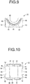
- the first half body 20 has a substantially semi-cylindrical shape.
- a first recessed groove 24 is formed penetrating in the front-back direction with a substantially semi-circular cross-section while opening to the lower surface of the first half body 20.
- the first half body 20 has an approximately semi-cylindrical shape that is convex to the upper side as a whole.
- a first intermediate member 26 is fixed to the radially middle portion of the first half body 20.
- the first intermediate member 26 is a rigid member formed of a metal or the like and has a substantially semi-cylindrical shape that is convex to the upper side.
- Each end portion in the axial direction of the first intermediate member 26 has a smaller diameter than that of the axially intermediate portion of the first intermediate member 26. Besides, both axial end portions of the first intermediate member 26 protrude axially outward from the axial end face of the first half body 20 to be covered by a first covering rubber 28, which is formed integrally with the first half body 20. Both ends and the central portion in the circumferential direction of the first intermediate member 26 are exposed from the first covering rubber 28.
- the first half body 20 has a first mountain portion 30 which protrudes radially outward at each end portion in the axial direction.
- the height dimension of the first mountain portion 30 gradually decreases from circumferentially opposite ends toward the center in the circumferential direction.
- the height dimension of the first mountain portion 30 is approximately zero.
- the outer circumferential surface of each axial end portion of the first half body 20 provided with the first mountain portion 30 is positioned on substantially the same arc across the circumferential entire length, at least in the axial center portion of the first mountain portion 30.
- the depth dimension of a first groove-shaped portion 32 formed axially between the first mountain portions 30, 30 gradually decreases from circumferentially opposite ends toward the center in the circumferential direction of the first half body 20. Consequently, the height dimension of the first mountain portion 30 gradually decreases toward the center in the circumferential direction.
- the outer circumferential surface of the circumferentially center portion of the first half body 20 where the height dimension of the first mountain portion 30 is substantially zero includes a flat pressure-receiving portion 34 extending linearly in the axial direction over the entire axial length.
- An end portion on the axially inner side of the first mountain portion 30 has a chamfered first inner inclined surface 36.
- the width dimension of the first inner inclined surface 36 gradually increases toward the end in the circumferential direction of the first half body 20.
- a chamfered first outer inclined surface 38 is provided at each end portion in the circumferential direction of the first half body 20, at the axially outer end edge portion of the first mountain portion 30.
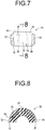
- the second half body 22 has a substantially rectangular block shape. Additionally, a second recessed groove 40 is formed penetrating in the front-back direction with a substantially semi-circular cross section while opening to the upper surface of the second half body 22. As a result, the second half body 22 has an irregular semi-tubular shape that is concave to the upper side as a whole. Further, a second intermediate member 42 is fixed to the radially middle portion of the second half body 22.
- the second intermediate member 42 is a rigid member formed of a metal or the like and has a substantially semi-cylindrical shape that is concave to the upper side.
- Each axial end portion of the second intermediate member 42 has a smaller diameter than that of the axially intermediate portion of the second intermediate member 42. Besides, both axial end portions of the second intermediate member 42 protrude axially outward from the axial end faces of the second half body 22 to be covered by a second covering rubber 44, which is formed integrally with the second half body 22. Both ends and the central portion in the circumferential direction of the second intermediate member 42 are exposed from the second covering rubber 44.
- the second half body 22 has a second mountain portion 46 which protrudes radially outward at each end portion in the axial direction.
- the second mountain portion 46 is formed projecting in the left and right side surfaces of the second half body 22, and is provided continuously with a nearly constant height dimension across the entire up-down length, as FIGS. 11 and 12 show.
- the height dimension of the second mountain portion 46 is nearly equal to the height dimension of the first mountain portion 30 in the circumferentially opposite ends of the first half body 20.
- the transverse cross section surface shape of the second mountain portion 46 is nearly equal to the transverse cross section surface shape of the first mountain portion 30 in the circumferentially opposite ends of the first half body 20.
- a second groove-shaped portion 48 is formed axially between the second mountain portions 46, 46 provided at both end portions in the axial direction, so as to open toward the left-right outside while extending in the up-down direction.
- the depth dimension of the second groove-shaped portion 48 is substantially constant over the entire up-down length.
- a second inner inclined surface 50 inclined outward in the axial direction as it goes toward the outside in the left-right direction is formed at the axially inner end edge portion of the second mountain portion 46.
- a second outer inclined surface 52 inclined inward in the left-right direction as it goes toward the axially outer side is formed at the axially outer end edge portion of the second mountain portion 46.
- the second inner and outer inclined surfaces 50, 52 of the second mountain portion 46 are formed to have substantially constant width dimensions over the entire up-down length.
- the first half body 20 and the second half body 22 are combined face-to-face with each other in the up-down direction, thereby constituting the tubular rubber elastic body 16.
- the first half body 20 and the second half body 22 are arranged to face each other.
- the circumferential ends of the first half body 20 and the circumferential ends of the second half body 22 are arranged in a direction in which they are butted against each other.
- the first half body 20 and the second half body 22 are combined so that they clamp the stabilizer bar 14 in the up-down direction.
- the stabilizer bar 14 is disposed to penetrate the rubber elastic body 16 in a state where it is inserted through the insertion hole 54.
- the inner circumferential surface of the rubber elastic body 16 is pressed against the outer circumferential surface of the stabilizer bar 14.
- An adhesive is applied to at least one of the groove inner surface of the first recessed groove 24 of the first half body 20 and the groove inner surface of the second recessed groove 40 of the second half body 22, and the outer circumferential surface of the stabilizer bar 14, whereby the stabilizer bushing is attached to the stabilizer bar 14 in an adhered state.
- the rubber elastic body 16 is constituted by combining the first half body 20 and the second half body 22, whereby the rubber elastic body 16 can easily be externally disposed and attached on and about the stabilizer bar 14.
- the first half body 20 and the second half body 22 are combined in the up-down direction, which is the direction of input of the main radial load on the rubber elastic body 16. This makes it possible to avoid the main radial load from acting as a shear force on each circumferential end portion of the first half body 20 and the second half body 22. As a result, stable support of the stabilizer bar 14 and stable exhibition of target spring characteristics, improvement in durability and the like are realized.
- the first mountain portion 30 of the first half body 20 and the left and right second mountain portions 46, 46 of the second half body 22 are arranged in series in the circumferential direction.
- the first mountain portion 30 and the left and right second mountain portions 46, 46 are continuous in the up-down direction.
- the bracket 18 is attached to the rubber elastic body 16.
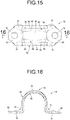
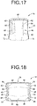
- the bracket 18 is a highly rigid member made of metal or the like, and as shown in FIGS. 13 to 18 , the bracket 18 has a structure wherein attachment portions 58, 58 are integrally formed on circumferentially opposite sides of a mounting portion 56 which is formed in a substantially semi-cylindrical shape.
- the mounting portion 56 has a generally semi-cylindrical shape as a whole, and groove-shaped concave parts 60 that are concave to the radial inside are formed to extend in the circumferential direction at axially opposite portions of the mounting portion 56. More specifically, the concave part 60 has a bottom wall portion 62 extending in the circumferential direction with a substantially arcuate cross section, an outside wall portion 64 which is positioned on the outside in the axial direction of the bottom wall portion 62 and spreading inclined inward in the radial direction as it goes to the axial outside. The concave part 60 also has an inside wall portion 66 which is located axially inward of the bottom wall portion 62 and extends so as to be inclined inward in the radial direction as it goes toward the axial inside.
- the depth dimension of the concave part 60 gradually decreases from circumferentially opposite ends of the mounting portion 56 toward the center in the circumferential direction.
- the depth dimension of the concave part 60 in the circumferentially center portion of the mounting portion 56 is substantially zero.
- a flat abutting portion 68 is provided at the center portion in the circumferential direction of the mounting portion 56.
- the flat abutting portion 68 is formed such that the axially intermediate portion extends linearly in the axial direction with substantially the same diameter as that of the bottom wall portion 62 of the concave part 60, while both axial end portions are constituted by the outside wall portion 64 and are inclined to the radial inside as it goes outward in the axial direction.
- a tapered part inclining radially inward toward the axial outside is constituted by the outside wall portion 64 of the concave part 60 including both axial end portions of the flat abutting portion 68, at the axially opposite end portions of the mounting portion 56.
- the attachment portion 58 is formed in a plate shape, and a bolt hole 70 is formed penetrating the attachment portion 58 in the up-down direction, namely the thickness direction.
- the attachment portion 58 is provided so as to extend laterally outward from the circumferential end portion of the mounting portion 56.
- the bracket 18 of the present practical embodiment is formed by press working of a plate material.
- the left and right sides of the mounting portion 56 are bent to integrally form the left and right attachment portions 58, 58, whereby deformation rigidity of the bracket 18 is efficiently secured.
- the connecting portions between the mounting portion 56 and the left and right attachment portions 58, 58 integrally include reinforcing ribs 72 bent so that both axial end portions thereof tilt upward as it goes outward in the axial direction.
- the strength of the connecting portions between the mounting portion 56 and the attachment portions 58, 58 also improves.
- the bracket 18 is attached to the rubber elastic body 16. That is, the mounting portion 56 of the bracket 18 is fitted to the rubber elastic body 16 from the upper side.
- the mounting portion 56 is superposed on the outer peripheral surface of the first half body 20 and the upper portion of the left and right side surfaces of the second half body 22 in contact with them.
- the left and right attachment portions 58, 58 are attached to a vehicle body 74 such as a sub frame. That is, bolts 76 inserted through the bolt holes 70 of the attachment portions 58, 58 are threaded onto the vehicle body 74, whereby the bracket 18 is fixed to the vehicle body 74 at the attachment portions 58, 58. Consequently, the stabilizer bar 14 is connected in a vibration-damping manner to the vehicle body 74 via the stabilizer bushing for adhesive use 12.
- the bracket 18 By fixing the bracket 18 to the vehicle body 74, the bracket 18 is fitted and attached to the outer circumferential surface of the rubber elastic body 16 in a non-adhesive way. Then, the bracket 18 is attached in a non-adhesive way to the rubber elastic body 16 adhered externally to and around the stabilizer bar 14.
- the stabilizer bar equipped with the stabilizer bushing 10 wherein the stabilizer bushing for adhesive use 12 is attached to the stabilizer bar 14 is constituted in an attached state to the vehicle body 74.
- the attachment portions 58, 58 of the bracket 18 are attached to the vehicle body 74, whereby the first half body 20 of the rubber elastic body 16 is pre-compressed in the radial directions between the bracket 18 and the stabilizer bar 14. Meanwhile, the second half body 22 of the rubber elastic body 16 is radially pre-compressed between the stabilizer bar 14 and the vehicle body 74.
- the first intermediate member 26 is fixed to the first half body 20, and the outer peripheral side and the radially inner side of the first half body 20 relative to the first intermediate member 26 are respectively radially pre-compressed.
- the second intermediate member 42 is fixed to the second half body 22, and the outer peripheral side and the radial inside of the second intermediate member 42 in the second half body 22 are respectively radially pre-compressed.
- the rubber elastic body 16 is pre-compressed in the radial directions as described above, whereby the axial end surfaces of the rubber elastic body 16 can be deformed so as to slightly bulge outward in the axial direction.
- first mountain portion 30 and the left and right second mountain portions 46, 46 of the rubber elastic body 16 are fitted into the concave part 60 provided in the mounting portion 56 of the bracket 18.
- the first mountain portion 30 and the left and right second mountain portions 46, 46 are abutted and superposed in the axial direction on the inside and outside wall portions 66, 64 of the concave part 60.
- the first mountain portion 30 and the left and right second mountain portions 46, 46 are abutted on and engaged with the inside and outside wall portions 66, 64 of the concave part 60 in the bracket 18 in the axial direction. Consequently, the rubber elastic body 16 is positioned relative to the bracket 18 in the axial direction.
- concave/convex mated parts 78 are provided between the rubber elastic body 16 and the bracket 18, so as to be abutted on and engaged with each other in the axial direction.
- the concave/convex mated part 78 is provided at each axial end portion of the stabilizer bushing for adhesive use 12.
- the height dimension of the first mountain portion 30 is small at the circumferential center of the first half body 20, while the depth dimension of the concave part 60 is small at the circumferential center of the mounting portion 56.
- the mated height dimension of the concave/convex mated part 78 is smaller at the circumferential center of the first half body 20 and the mounting portion 56, than at the both circumferential sides.
- the mated height dimension of the concave/convex mated part 78 continuously decreases from both circumferential ends of the first half body 20 to the circumferential center.
- the height dimension of the first mountain portion 30 at the both circumferential ends of the first half body 20 and the height dimension of the second mountain portion 46 are substantially the same.
- the mated height dimension of the concave/convex mated part 78 at the circumferential center of the first half body 20 is smaller than the mated height dimension of the concave/convex mated part 78 in the second half body 22.
- both axial end portions of the mounting portion 56 are formed as the outside wall portions 64, 64 that are inclined inward in the radial direction as it goes to the axial outside.
- the outer peripheral end portion of the rubber elastic body 16 is arranged between the outside wall portions 64, 64 in the axial direction.
- the rubber elastic body 16 is positioned in the axial direction relative to the bracket 18 also by abutting engagement with the outside wall portions 64, 64 in the axial direction.
- the stabilizer bushing for adhesive use 12 when compression force in the up-down direction is input on the circumferentially center portion of the first half body 20 of the rubber elastic body 16, the compression force acting on the first half body 20 is less likely to generate a component force to the axial outside.
- the mated height dimension of the concave/convex mated part 78 which are constituted by fitting the first mountain portion 30 into the concave part 60, is small at the circumferentially center portion of the first half body 20 and the mounting portion 56.
- the circumferentially center portion of the outer circumferential surface of the first half body 20 on which the main radial load is exerted is provided with the flat pressure-receiving portion 34.
- the height dimension of the first mountain portion 30 is substantially zero in the flat pressure-receiving portion 34, and the first mountain portion 30 substantially disappears.
- the mated height dimension of the concave/convex mated part 78 is substantially zero at the circumferentially center portion of the first half body 20. Therefore, with respect to the up-down compression force exerted on the circumferentially center portion of the first half body 20, extrusion of the first mountain portion 30 to the axial outside by the inside wall portion 66 of the concave part 60 of the bracket 18 being pressed against the first mountain portion 30 is less likely to occur in the circumferentially center portion of the first half body 20 that is greatly compressed.
- the rubber elastic body 16 is less likely to be deformed or displaced axially outward relative to the bracket 18. Therefore, the rubber elastic body 16 is scarcely dislodged from the bracket 18 in the axial direction.
- the concave/convex mated parts 78 constituted by the first mountain portion 30, the left and right second mountain portions 46, 46 and the concave part 60.
- the rubber elastic body 16 and the bracket 18 are positioned in the axial direction.
- the flat pressure-receiving portion 34 where the height of the first mountain portion 30 is substantially zero.
- the height dimension of the first mountain portion 30 gradually decreases from the circumferentially opposite ends toward the flat pressure-receiving portion 34 in the circumferentially center portion. This prevents local concentration of stress in the elastic deformation of the rubber elastic body 16 including the first mountain portion 30, whereby the durability of the rubber elastic body 16 improves.
- the first intermediate member 26 and the second intermediate member 42 are fixed to the radially middle portion of the rubber elastic body 16, thereby adjusting the spring characteristics in the radial direction, the axial direction, and the torsional direction of the rubber elastic body 16.
- the upper portion of the outer peripheral portion of the rubber elastic body 16 is compressed in the radial direction between the first intermediate member 26 and the bracket 18. Consequently, when the rubber elastic body 16 is compressed in the up-down direction, the displacement amount of the outer circumferential surface of the rubber elastic body 16 superposed on the bracket 18 relative to the bracket 18 is reduced, so that prevention of noise and improvement in durability are more advantageously realized.
- the rubber elastic body is not necessarily limited to the structure wherein the first half body and the second half body are combined.
- the rubber elastic body has a tubular shape that is integrally formed, and the rubber elastic body is divided by a slit in a part in the circumferential direction so that the stabilizer bar may be inserted into the insertion hole of the rubber elastic body through the slit.
- the structure wherein the height dimension of the first mountain portion 30 is approximately zero at the circumferentially center portion of the first half body 20, which is the position of input of the main radial load.
- the rubber elastic body will do as long as the height dimension of the first mountain portion 30 is smaller at the position of input of the main radial load than at the other portion. That is, the height dimension of the first mountain portion 30 is not necessarily zero at the position of input of the main radial load.
- the first mountain portion 30 can be provided continuously so that the height dimension is larger than zero over the entire circumference of the first half body 20. In this case, the height dimension of the first mountain portion 30 in the circumferentially center portion is made smaller than the height dimension of the first mountain portion 30 on the circumferentially opposite side portions.
- the mated height dimension of the concave/convex mated part in the present invention is a relative one. That is, it is also possible to provide a valley portion extending in the circumferential direction at both sides of the axially center portion of the rubber elastic body 16, thereby making the axially opposite sides the mountain portions, relative to the axially center portion. Alternatively, it is possible to provide the mountain portions that extend in the circumferential direction, by protruding both axial side portions of the rubber elastic body 16 further radially outward than the axially center portion.
- the height dimension of the first mountain portion 30 gradually decreases from both circumferential ends toward the circumferentially center portion
- the mated height dimension of the concave/convex mated part 78 gradually decreases toward the circumferential center.
- the mated height dimension of the concave/convex mated part 78 may be partially reduced, at the position of input of the main radial load.
- the mated height dimension of the concave/convex mated part 78 may be reduced toward the position of input of the main radial load, in a stepwise manner.
- the concave/convex mated part 78 is provided so as to extend in the circumferential direction of the rubber elastic body 16.
- the concave/convex mated part 78 does not necessarily have to extend in the circumferential direction.
- the concave/convex mated part 78 is not necessarily provided at each axial end as long as it is provided on each axial side of the rubber elastic body 16 and the bracket 18.
- a protruding portion of the rubber elastic body 16 is provided on the axial outside of the first and second mountain portions 30, 46 that constitute the concave/convex mated part 78.
- a protruding part of the bracket 18 is provided at axial outside of the concave part 60 constituting the concave/convex mated part 78.
- the main radial load may be input at a position separated from the left-right central portion, in a radial direction inclined relative to the up-down direction.
- an intermediate member such as the first intermediate member 26 and the second intermediate member 42 shown in the above-described practical embodiment is not indispensable. Further, the intermediate member does not have to be divided into the first intermediate member 26 and the second intermediate member 42 as the above-described practical embodiment. For example, it is possible to employ the intermediate member having a C-shaped cross section extending with a length that is shorter than one circumference in the circumferential direction of the rubber elastic body 16.
- the structure wherein the rubber elastic body 16 attached to the stabilizer bar 14 in an externally attached state is disposed between the bracket 18 and the vehicle body 74 in the up-down direction.
- the bracket comprises an upper bracket and a lower bracket, and the upper and lower brackets are mounted so as to respectively cover the upper and lower half circumferences of the outer peripheral surface of the rubber elastic body, and the rubber elastic body is pre-compressed between the upper and lower brackets, etc.
Landscapes
- Engineering & Computer Science (AREA)
- Mechanical Engineering (AREA)
- General Engineering & Computer Science (AREA)
- Chemical & Material Sciences (AREA)
- Combustion & Propulsion (AREA)
- Physics & Mathematics (AREA)
- Acoustics & Sound (AREA)
- Aviation & Aerospace Engineering (AREA)
- Springs (AREA)
- Vehicle Body Suspensions (AREA)
- Vibration Prevention Devices (AREA)
Applications Claiming Priority (1)
| Application Number | Priority Date | Filing Date | Title |
|---|---|---|---|
| JP2018031659A JP6948964B2 (ja) | 2018-02-26 | 2018-02-26 | 接着用スタビライザブッシュおよびスタビライザブッシュ付スタビライザバー |
Publications (2)
| Publication Number | Publication Date |
|---|---|
| EP3530500A1 true EP3530500A1 (de) | 2019-08-28 |
| EP3530500B1 EP3530500B1 (de) | 2022-07-06 |
Family
ID=65576182
Family Applications (1)
| Application Number | Title | Priority Date | Filing Date |
|---|---|---|---|
| EP19159042.1A Active EP3530500B1 (de) | 2018-02-26 | 2019-02-25 | Stabilisatorbuchse zur haftverwendung und mit der stabilisatorbuchse ausgestattete stabilisatorstange |
Country Status (4)
| Country | Link |
|---|---|
| US (1) | US10994583B2 (de) |
| EP (1) | EP3530500B1 (de) |
| JP (1) | JP6948964B2 (de) |
| CN (1) | CN110195754B (de) |
Cited By (1)
| Publication number | Priority date | Publication date | Assignee | Title |
|---|---|---|---|---|
| CN112460387A (zh) * | 2020-11-12 | 2021-03-09 | 广州艾目易科技有限公司 | 一种光学定位系统中的固定装置 |
Families Citing this family (7)
| Publication number | Priority date | Publication date | Assignee | Title |
|---|---|---|---|---|
| JP2020523240A (ja) * | 2017-06-14 | 2020-08-06 | ティッセンクルップ フェデルン ウント シュタビリサトレン ゲゼルシャフト ミット ベシュレンクテル ハフツングThyssenKrupp Federn und Stabilisatoren GmbH | 車両スタビライザバー用スタビライザバー接着マウント、スタビライザバー接着マウントを有する車両スタビライザバー、およびスタビライザバー接着マウントを車両スタビライザバーに形成する方法 |
| JP7284647B2 (ja) * | 2019-06-20 | 2023-05-31 | Toyo Tire株式会社 | スタビライザブッシュ |
| JP7409979B2 (ja) * | 2020-06-29 | 2024-01-09 | 住友理工株式会社 | サスペンションブッシュ |
| DE102020211001A1 (de) | 2020-09-01 | 2022-03-03 | Zf Friedrichshafen Ag | Lageranordnung |
| DE102020211002B4 (de) | 2020-09-01 | 2022-06-02 | Zf Friedrichshafen Ag | Lageranordnung |
| JP7085667B1 (ja) * | 2021-03-31 | 2022-06-16 | 住友理工株式会社 | 摺動ブッシュ |
| WO2025028106A1 (ja) | 2023-07-31 | 2025-02-06 | 株式会社プロスパイラ | ブッシュ、防振構造体、及び、防振構造体製造方法 |
Citations (6)
| Publication number | Priority date | Publication date | Assignee | Title |
|---|---|---|---|---|
| KR20100018872A (ko) * | 2008-08-07 | 2010-02-18 | 현대자동차주식회사 | 차량용 서스펜션의 스태빌라이저 바 마운팅 장치 |
| KR101470799B1 (ko) * | 2014-09-01 | 2014-12-12 | 주식회사 성림티앤티 | 차량용 스테빌라이저 바 마운팅 부시 |
| EP2855178B1 (de) * | 2012-05-29 | 2016-04-20 | Renault S.A.S. | Schwenkbare lageranordnung für einen stabilisator |
| DE102015104864A1 (de) * | 2015-03-30 | 2016-10-06 | Thyssenkrupp Ag | Lagerelement für einen Stabilisator eines Fahrzeugs |
| DE102016010313A1 (de) * | 2015-09-17 | 2017-03-23 | Sumitomo Riko Company Limited | Stabilisatorbuchse und selbige verwendende buchsenbestückte Stabilisatorstange |
| JP2017149371A (ja) | 2016-02-26 | 2017-08-31 | 住友理工株式会社 | 接着タイプのスタビライザブッシュ |
Family Cites Families (35)
| Publication number | Priority date | Publication date | Assignee | Title |
|---|---|---|---|---|
| DE3531340A1 (de) * | 1985-09-03 | 1987-03-12 | Lemfoerder Metallwaren Ag | Lager mit geteiltem gehaeuse fuer stabilisatoren oder dergleichen in kraftfahrzeugen |
| EP0272851A3 (de) * | 1986-12-22 | 1989-03-15 | Farathane, Inc. | Lagerung |
| JPH04114807U (ja) | 1991-03-26 | 1992-10-09 | 東海ゴム工業株式会社 | スタビライザバーブツシユ |
| JP3047501B2 (ja) * | 1991-04-15 | 2000-05-29 | 豊田合成株式会社 | 筒状防振ブッシュ |
| JP2874399B2 (ja) * | 1991-09-18 | 1999-03-24 | 日産自動車株式会社 | スタビライザ取付装置 |
| JPH084814A (ja) * | 1994-06-22 | 1996-01-12 | Kurashiki Kako Co Ltd | ブッシュ組立体 |
| DE19746357C1 (de) * | 1997-10-21 | 1999-05-12 | Vorwerk & Sohn | Gummi/Metall-Lager zur Anlenkung eines Stabilisators an einem Kraftfahrzeugaufbau |
| US6889988B2 (en) * | 2002-04-17 | 2005-05-10 | Visteon Global Technologies, Inc. | Variable rate gripped bushing system |
| KR100527718B1 (ko) * | 2003-07-15 | 2005-11-09 | 현대자동차주식회사 | 스테빌라이저의 고정장치 |
| WO2006008803A1 (ja) * | 2004-07-20 | 2006-01-26 | Toyo Tire & Rubber Co., Ltd. | スタビライザブッシュ |
| JP2006069233A (ja) * | 2004-08-31 | 2006-03-16 | Toyo Tire & Rubber Co Ltd | ゴムブッシュ付きスタビライザーバーの製造方法 |
| JP2005212780A (ja) | 2005-02-14 | 2005-08-11 | Toyo Tire & Rubber Co Ltd | スタビライザブッシュ |
| JP2007253739A (ja) * | 2006-03-22 | 2007-10-04 | Tokai Rubber Ind Ltd | スタビライザブッシュ |
| KR100872292B1 (ko) * | 2006-06-27 | 2008-12-05 | 대원강업주식회사 | 차량용 스태빌라이저 바의 마운팅 장치 |
| DE102006032826A1 (de) * | 2006-07-14 | 2008-01-17 | Carl Freudenberg Kg | Stabilisator zur Anlenkung einer Stabilisatorstange an einem Kraftfahrzeug |
| JP2008213751A (ja) * | 2007-03-07 | 2008-09-18 | Tokai Rubber Ind Ltd | 防振ブッシュ付スタビライザバー及びその製造方法 |
| JP5622654B2 (ja) * | 2011-05-23 | 2014-11-12 | 住友理工株式会社 | 車両用スタビライザブッシュとその製造方法 |
| JP5704008B2 (ja) * | 2011-07-29 | 2015-04-22 | マツダ株式会社 | スタビライザーバー取付用ブッシュ |
| US8505940B1 (en) * | 2012-04-09 | 2013-08-13 | GM Global Technology Operations LLC | Stabilizer bar bushing attachment assembly |
| CN102874066A (zh) * | 2012-09-26 | 2013-01-16 | 柳州孔辉汽车科技有限公司 | 一种稳定杆衬套组件 |
| CN202863074U (zh) * | 2012-11-06 | 2013-04-10 | 北京汽车股份有限公司 | 稳定杆衬套、稳定杆组件及汽车 |
| CN203046805U (zh) * | 2013-01-18 | 2013-07-10 | 安徽奥丰汽车配件有限公司 | 新型汽车横向稳定连杆橡胶减震衬套 |
| JP5638656B2 (ja) | 2013-04-19 | 2014-12-10 | 日本発條株式会社 | スタビライザ用ブッシュ |
| CN203344686U (zh) * | 2013-06-26 | 2013-12-18 | 上海大众汽车有限公司 | 汽车稳定杆 |
| CN203995551U (zh) * | 2014-04-11 | 2014-12-10 | 广州汽车集团股份有限公司 | 稳定杆衬套、稳定杆安装装置、悬架及车辆 |
| JP6176196B2 (ja) * | 2014-07-02 | 2017-08-09 | トヨタ自動車株式会社 | スタビライザバー支持装置 |
| JP6542516B2 (ja) * | 2014-08-28 | 2019-07-10 | 三菱製鋼株式会社 | ゴムブッシュ付きスタビライザバーの製造方法 |
| JP6347226B2 (ja) * | 2015-04-16 | 2018-06-27 | トヨタ自動車株式会社 | スタビライザバー取付装置、スタビライザバー取付用ブラケット |
| CN104786775A (zh) * | 2015-04-29 | 2015-07-22 | 安徽江淮汽车股份有限公司 | 一种稳定杆衬套组件 |
| KR101570320B1 (ko) | 2015-06-10 | 2015-11-18 | 주식회사 성림티앤티 | 차량의 스테빌라이저 바 마운팅용 본딩형 부시 |
| CN205118090U (zh) * | 2015-11-24 | 2016-03-30 | 安徽江淮汽车股份有限公司 | 一种稳定杆衬套及稳定杆总成 |
| JP6746304B2 (ja) * | 2015-12-02 | 2020-08-26 | 日本発條株式会社 | 車両用スタビライザ装置 |
| JP6681230B2 (ja) * | 2016-03-16 | 2020-04-15 | 住友理工株式会社 | スタビライザブッシュの取付構造とスタビライザブッシュの製造方法 |
| JP6824704B2 (ja) * | 2016-11-16 | 2021-02-03 | Toyo Tire株式会社 | スタビライザブッシュ |
| JP6754311B2 (ja) * | 2017-02-28 | 2020-09-09 | 住友理工株式会社 | スタビライザブッシュ |
-
2018
- 2018-02-26 JP JP2018031659A patent/JP6948964B2/ja active Active
-
2019
- 2019-02-21 US US16/281,613 patent/US10994583B2/en active Active
- 2019-02-22 CN CN201910133078.3A patent/CN110195754B/zh active Active
- 2019-02-25 EP EP19159042.1A patent/EP3530500B1/de active Active
Patent Citations (6)
| Publication number | Priority date | Publication date | Assignee | Title |
|---|---|---|---|---|
| KR20100018872A (ko) * | 2008-08-07 | 2010-02-18 | 현대자동차주식회사 | 차량용 서스펜션의 스태빌라이저 바 마운팅 장치 |
| EP2855178B1 (de) * | 2012-05-29 | 2016-04-20 | Renault S.A.S. | Schwenkbare lageranordnung für einen stabilisator |
| KR101470799B1 (ko) * | 2014-09-01 | 2014-12-12 | 주식회사 성림티앤티 | 차량용 스테빌라이저 바 마운팅 부시 |
| DE102015104864A1 (de) * | 2015-03-30 | 2016-10-06 | Thyssenkrupp Ag | Lagerelement für einen Stabilisator eines Fahrzeugs |
| DE102016010313A1 (de) * | 2015-09-17 | 2017-03-23 | Sumitomo Riko Company Limited | Stabilisatorbuchse und selbige verwendende buchsenbestückte Stabilisatorstange |
| JP2017149371A (ja) | 2016-02-26 | 2017-08-31 | 住友理工株式会社 | 接着タイプのスタビライザブッシュ |
Cited By (2)
| Publication number | Priority date | Publication date | Assignee | Title |
|---|---|---|---|---|
| CN112460387A (zh) * | 2020-11-12 | 2021-03-09 | 广州艾目易科技有限公司 | 一种光学定位系统中的固定装置 |
| CN112460387B (zh) * | 2020-11-12 | 2021-08-17 | 广州艾目易科技有限公司 | 一种光学定位系统中的固定装置 |
Also Published As
| Publication number | Publication date |
|---|---|
| US10994583B2 (en) | 2021-05-04 |
| JP6948964B2 (ja) | 2021-10-13 |
| CN110195754A (zh) | 2019-09-03 |
| EP3530500B1 (de) | 2022-07-06 |
| US20190263214A1 (en) | 2019-08-29 |
| CN110195754B (zh) | 2021-11-16 |
| JP2019147408A (ja) | 2019-09-05 |
Similar Documents
| Publication | Publication Date | Title |
|---|---|---|
| US10994583B2 (en) | Stabilizer bushing for adhesive use and stabilizer bar equipped with stabilizer bushing | |
| JP5595458B2 (ja) | 防振装置 | |
| US9981524B2 (en) | Stabilizer bushing and bushing-equipped stabilizer bar using the same | |
| US9518628B2 (en) | Tubular vibration-damping device | |
| JP6754311B2 (ja) | スタビライザブッシュ | |
| US20110229254A1 (en) | Tool joint structure | |
| JP6424299B1 (ja) | トルクロッド | |
| CN105378330B (zh) | 隔振装置 | |
| JP6309410B2 (ja) | 鞍乗り型車両のエンジン支持構造 | |
| JP2016064721A5 (de) | ||
| JP6469031B2 (ja) | センターベアリング | |
| US20250109779A1 (en) | Bush | |
| CN101338808B (zh) | 减振装置及其制造方法 | |
| JP6368728B2 (ja) | 接着タイプのスタビライザブッシュ | |
| KR100435273B1 (ko) | 자동차용 엔진 마운트 | |
| JP7329429B2 (ja) | ブラケット付き筒型防振装置 | |
| JP4442371B2 (ja) | トルクロッド | |
| JP4283853B2 (ja) | リンク装置 | |
| US20250128565A1 (en) | Stabilizer bushing | |
| JP2023172725A (ja) | 筒形防振装置とそれを用いたトルクロッド | |
| WO2026070097A1 (ja) | ストッパ用緩衝体 | |
| JP2026058824A (ja) | ストッパ用緩衝体 | |
| KR102082831B1 (ko) | 로워암과 볼조인트의 결합구조 | |
| JP2024141550A (ja) | 取付ゴム部材 | |
| JP2004138134A (ja) | ブッシュ構造 |
Legal Events
| Date | Code | Title | Description |
|---|---|---|---|
| PUAI | Public reference made under article 153(3) epc to a published international application that has entered the european phase |
Free format text: ORIGINAL CODE: 0009012 |
|
| STAA | Information on the status of an ep patent application or granted ep patent |
Free format text: STATUS: REQUEST FOR EXAMINATION WAS MADE |
|
| 17P | Request for examination filed |
Effective date: 20190228 |
|
| AK | Designated contracting states |
Kind code of ref document: A1 Designated state(s): AL AT BE BG CH CY CZ DE DK EE ES FI FR GB GR HR HU IE IS IT LI LT LU LV MC MK MT NL NO PL PT RO RS SE SI SK SM TR |
|
| AX | Request for extension of the european patent |
Extension state: BA ME |
|
| STAA | Information on the status of an ep patent application or granted ep patent |
Free format text: STATUS: EXAMINATION IS IN PROGRESS |
|
| RBV | Designated contracting states (corrected) |
Designated state(s): AL AT BE BG CH CY CZ DE DK EE ES FI FR GB GR HR HU IE IS IT LI LT LU LV MC MK MT NL NO PL PT RO RS SE SI SK SM TR |
|
| 17Q | First examination report despatched |
Effective date: 20200211 |
|
| GRAP | Despatch of communication of intention to grant a patent |
Free format text: ORIGINAL CODE: EPIDOSNIGR1 |
|
| STAA | Information on the status of an ep patent application or granted ep patent |
Free format text: STATUS: GRANT OF PATENT IS INTENDED |
|
| INTG | Intention to grant announced |
Effective date: 20220323 |
|
| GRAS | Grant fee paid |
Free format text: ORIGINAL CODE: EPIDOSNIGR3 |
|
| GRAA | (expected) grant |
Free format text: ORIGINAL CODE: 0009210 |
|
| STAA | Information on the status of an ep patent application or granted ep patent |
Free format text: STATUS: THE PATENT HAS BEEN GRANTED |
|
| AK | Designated contracting states |
Kind code of ref document: B1 Designated state(s): AL AT BE BG CH CY CZ DE DK EE ES FI FR GB GR HR HU IE IS IT LI LT LU LV MC MK MT NL NO PL PT RO RS SE SI SK SM TR |
|
| REG | Reference to a national code |
Ref country code: AT Ref legal event code: REF Ref document number: 1502629 Country of ref document: AT Kind code of ref document: T Effective date: 20220715 Ref country code: CH Ref legal event code: EP |
|
| REG | Reference to a national code |
Ref country code: DE Ref legal event code: R096 Ref document number: 602019016583 Country of ref document: DE |
|
| REG | Reference to a national code |
Ref country code: IE Ref legal event code: FG4D |
|
| REG | Reference to a national code |
Ref country code: LT Ref legal event code: MG9D |
|
| REG | Reference to a national code |
Ref country code: NL Ref legal event code: MP Effective date: 20220706 |
|
| PG25 | Lapsed in a contracting state [announced via postgrant information from national office to epo] |
Ref country code: SE Free format text: LAPSE BECAUSE OF FAILURE TO SUBMIT A TRANSLATION OF THE DESCRIPTION OR TO PAY THE FEE WITHIN THE PRESCRIBED TIME-LIMIT Effective date: 20220706 Ref country code: RS Free format text: LAPSE BECAUSE OF FAILURE TO SUBMIT A TRANSLATION OF THE DESCRIPTION OR TO PAY THE FEE WITHIN THE PRESCRIBED TIME-LIMIT Effective date: 20220706 Ref country code: PT Free format text: LAPSE BECAUSE OF FAILURE TO SUBMIT A TRANSLATION OF THE DESCRIPTION OR TO PAY THE FEE WITHIN THE PRESCRIBED TIME-LIMIT Effective date: 20221107 Ref country code: NO Free format text: LAPSE BECAUSE OF FAILURE TO SUBMIT A TRANSLATION OF THE DESCRIPTION OR TO PAY THE FEE WITHIN THE PRESCRIBED TIME-LIMIT Effective date: 20221006 Ref country code: NL Free format text: LAPSE BECAUSE OF FAILURE TO SUBMIT A TRANSLATION OF THE DESCRIPTION OR TO PAY THE FEE WITHIN THE PRESCRIBED TIME-LIMIT Effective date: 20220706 Ref country code: LV Free format text: LAPSE BECAUSE OF FAILURE TO SUBMIT A TRANSLATION OF THE DESCRIPTION OR TO PAY THE FEE WITHIN THE PRESCRIBED TIME-LIMIT Effective date: 20220706 Ref country code: LT Free format text: LAPSE BECAUSE OF FAILURE TO SUBMIT A TRANSLATION OF THE DESCRIPTION OR TO PAY THE FEE WITHIN THE PRESCRIBED TIME-LIMIT Effective date: 20220706 Ref country code: FI Free format text: LAPSE BECAUSE OF FAILURE TO SUBMIT A TRANSLATION OF THE DESCRIPTION OR TO PAY THE FEE WITHIN THE PRESCRIBED TIME-LIMIT Effective date: 20220706 Ref country code: ES Free format text: LAPSE BECAUSE OF FAILURE TO SUBMIT A TRANSLATION OF THE DESCRIPTION OR TO PAY THE FEE WITHIN THE PRESCRIBED TIME-LIMIT Effective date: 20220706 |
|
| REG | Reference to a national code |
Ref country code: AT Ref legal event code: MK05 Ref document number: 1502629 Country of ref document: AT Kind code of ref document: T Effective date: 20220706 |
|
| PG25 | Lapsed in a contracting state [announced via postgrant information from national office to epo] |
Ref country code: PL Free format text: LAPSE BECAUSE OF FAILURE TO SUBMIT A TRANSLATION OF THE DESCRIPTION OR TO PAY THE FEE WITHIN THE PRESCRIBED TIME-LIMIT Effective date: 20220706 Ref country code: IS Free format text: LAPSE BECAUSE OF FAILURE TO SUBMIT A TRANSLATION OF THE DESCRIPTION OR TO PAY THE FEE WITHIN THE PRESCRIBED TIME-LIMIT Effective date: 20221106 Ref country code: HR Free format text: LAPSE BECAUSE OF FAILURE TO SUBMIT A TRANSLATION OF THE DESCRIPTION OR TO PAY THE FEE WITHIN THE PRESCRIBED TIME-LIMIT Effective date: 20220706 Ref country code: GR Free format text: LAPSE BECAUSE OF FAILURE TO SUBMIT A TRANSLATION OF THE DESCRIPTION OR TO PAY THE FEE WITHIN THE PRESCRIBED TIME-LIMIT Effective date: 20221007 |
|
| REG | Reference to a national code |
Ref country code: DE Ref legal event code: R097 Ref document number: 602019016583 Country of ref document: DE |
|
| PG25 | Lapsed in a contracting state [announced via postgrant information from national office to epo] |
Ref country code: SM Free format text: LAPSE BECAUSE OF FAILURE TO SUBMIT A TRANSLATION OF THE DESCRIPTION OR TO PAY THE FEE WITHIN THE PRESCRIBED TIME-LIMIT Effective date: 20220706 Ref country code: RO Free format text: LAPSE BECAUSE OF FAILURE TO SUBMIT A TRANSLATION OF THE DESCRIPTION OR TO PAY THE FEE WITHIN THE PRESCRIBED TIME-LIMIT Effective date: 20220706 Ref country code: DK Free format text: LAPSE BECAUSE OF FAILURE TO SUBMIT A TRANSLATION OF THE DESCRIPTION OR TO PAY THE FEE WITHIN THE PRESCRIBED TIME-LIMIT Effective date: 20220706 Ref country code: CZ Free format text: LAPSE BECAUSE OF FAILURE TO SUBMIT A TRANSLATION OF THE DESCRIPTION OR TO PAY THE FEE WITHIN THE PRESCRIBED TIME-LIMIT Effective date: 20220706 Ref country code: AT Free format text: LAPSE BECAUSE OF FAILURE TO SUBMIT A TRANSLATION OF THE DESCRIPTION OR TO PAY THE FEE WITHIN THE PRESCRIBED TIME-LIMIT Effective date: 20220706 |
|
| PLBE | No opposition filed within time limit |
Free format text: ORIGINAL CODE: 0009261 |
|
| STAA | Information on the status of an ep patent application or granted ep patent |
Free format text: STATUS: NO OPPOSITION FILED WITHIN TIME LIMIT |
|
| PG25 | Lapsed in a contracting state [announced via postgrant information from national office to epo] |
Ref country code: SK Free format text: LAPSE BECAUSE OF FAILURE TO SUBMIT A TRANSLATION OF THE DESCRIPTION OR TO PAY THE FEE WITHIN THE PRESCRIBED TIME-LIMIT Effective date: 20220706 Ref country code: EE Free format text: LAPSE BECAUSE OF FAILURE TO SUBMIT A TRANSLATION OF THE DESCRIPTION OR TO PAY THE FEE WITHIN THE PRESCRIBED TIME-LIMIT Effective date: 20220706 |
|
| 26N | No opposition filed |
Effective date: 20230411 |
|
| PG25 | Lapsed in a contracting state [announced via postgrant information from national office to epo] |
Ref country code: AL Free format text: LAPSE BECAUSE OF FAILURE TO SUBMIT A TRANSLATION OF THE DESCRIPTION OR TO PAY THE FEE WITHIN THE PRESCRIBED TIME-LIMIT Effective date: 20220706 |
|
| PG25 | Lapsed in a contracting state [announced via postgrant information from national office to epo] |
Ref country code: SI Free format text: LAPSE BECAUSE OF FAILURE TO SUBMIT A TRANSLATION OF THE DESCRIPTION OR TO PAY THE FEE WITHIN THE PRESCRIBED TIME-LIMIT Effective date: 20220706 |
|
| PG25 | Lapsed in a contracting state [announced via postgrant information from national office to epo] |
Ref country code: MC Free format text: LAPSE BECAUSE OF FAILURE TO SUBMIT A TRANSLATION OF THE DESCRIPTION OR TO PAY THE FEE WITHIN THE PRESCRIBED TIME-LIMIT Effective date: 20220706 |
|
| REG | Reference to a national code |
Ref country code: CH Ref legal event code: PL |
|
| REG | Reference to a national code |
Ref country code: BE Ref legal event code: MM Effective date: 20230228 |
|
| PG25 | Lapsed in a contracting state [announced via postgrant information from national office to epo] |
Ref country code: LU Free format text: LAPSE BECAUSE OF NON-PAYMENT OF DUE FEES Effective date: 20230225 Ref country code: LI Free format text: LAPSE BECAUSE OF NON-PAYMENT OF DUE FEES Effective date: 20230228 Ref country code: CH Free format text: LAPSE BECAUSE OF NON-PAYMENT OF DUE FEES Effective date: 20230228 |
|
| REG | Reference to a national code |
Ref country code: IE Ref legal event code: MM4A |
|
| PG25 | Lapsed in a contracting state [announced via postgrant information from national office to epo] |
Ref country code: IT Free format text: LAPSE BECAUSE OF FAILURE TO SUBMIT A TRANSLATION OF THE DESCRIPTION OR TO PAY THE FEE WITHIN THE PRESCRIBED TIME-LIMIT Effective date: 20220706 Ref country code: IE Free format text: LAPSE BECAUSE OF NON-PAYMENT OF DUE FEES Effective date: 20230225 |
|
| REG | Reference to a national code |
Ref country code: DE Ref legal event code: R084 Ref document number: 602019016583 Country of ref document: DE |
|
| PG25 | Lapsed in a contracting state [announced via postgrant information from national office to epo] |
Ref country code: BE Free format text: LAPSE BECAUSE OF NON-PAYMENT OF DUE FEES Effective date: 20230228 |
|
| REG | Reference to a national code |
Ref country code: GB Ref legal event code: 746 Effective date: 20240524 |
|
| PG25 | Lapsed in a contracting state [announced via postgrant information from national office to epo] |
Ref country code: BG Free format text: LAPSE BECAUSE OF FAILURE TO SUBMIT A TRANSLATION OF THE DESCRIPTION OR TO PAY THE FEE WITHIN THE PRESCRIBED TIME-LIMIT Effective date: 20220706 |
|
| PG25 | Lapsed in a contracting state [announced via postgrant information from national office to epo] |
Ref country code: BG Free format text: LAPSE BECAUSE OF FAILURE TO SUBMIT A TRANSLATION OF THE DESCRIPTION OR TO PAY THE FEE WITHIN THE PRESCRIBED TIME-LIMIT Effective date: 20220706 |
|
| REG | Reference to a national code |
Ref country code: DE Ref legal event code: R081 Ref document number: 602019016583 Country of ref document: DE Owner name: SUMITOMO RIKO COMPANY LIMITED, KOMAKI-SHI, JP Free format text: FORMER OWNERS: SUMITOMO RIKO COMPANY LIMITED, KOMAKI-SHI, AICHI-KEN, JP; TOYOTA JIDOSHA KABUSHIKI KAISHA, TOYOTA-SHI, AICHI-KEN, JP |
|
| REG | Reference to a national code |
Ref country code: GB Ref legal event code: 732E Free format text: REGISTERED BETWEEN 20250123 AND 20250128 |
|
| PGFP | Annual fee paid to national office [announced via postgrant information from national office to epo] |
Ref country code: DE Payment date: 20241231 Year of fee payment: 7 |
|
| PGFP | Annual fee paid to national office [announced via postgrant information from national office to epo] |
Ref country code: GB Payment date: 20250102 Year of fee payment: 7 |
|
| PG25 | Lapsed in a contracting state [announced via postgrant information from national office to epo] |
Ref country code: CY Free format text: LAPSE BECAUSE OF FAILURE TO SUBMIT A TRANSLATION OF THE DESCRIPTION OR TO PAY THE FEE WITHIN THE PRESCRIBED TIME-LIMIT; INVALID AB INITIO Effective date: 20190225 |
|
| PG25 | Lapsed in a contracting state [announced via postgrant information from national office to epo] |
Ref country code: HU Free format text: LAPSE BECAUSE OF FAILURE TO SUBMIT A TRANSLATION OF THE DESCRIPTION OR TO PAY THE FEE WITHIN THE PRESCRIBED TIME-LIMIT; INVALID AB INITIO Effective date: 20190225 |
|
| PG25 | Lapsed in a contracting state [announced via postgrant information from national office to epo] |
Ref country code: TR Free format text: LAPSE BECAUSE OF FAILURE TO SUBMIT A TRANSLATION OF THE DESCRIPTION OR TO PAY THE FEE WITHIN THE PRESCRIBED TIME-LIMIT Effective date: 20220706 |
|
| PGFP | Annual fee paid to national office [announced via postgrant information from national office to epo] |
Ref country code: FR Payment date: 20251231 Year of fee payment: 8 |