EP3527757B1 - Riegelverschlusssystem und türanlage - Google Patents
Riegelverschlusssystem und türanlage Download PDFInfo
- Publication number
- EP3527757B1 EP3527757B1 EP18156788.4A EP18156788A EP3527757B1 EP 3527757 B1 EP3527757 B1 EP 3527757B1 EP 18156788 A EP18156788 A EP 18156788A EP 3527757 B1 EP3527757 B1 EP 3527757B1
- Authority
- EP
- European Patent Office
- Prior art keywords
- locking
- bolt
- hook
- axis
- locking hook
- Prior art date
- Legal status (The legal status is an assumption and is not a legal conclusion. Google has not performed a legal analysis and makes no representation as to the accuracy of the status listed.)
- Active
Links
Images


Classifications
-
- E—FIXED CONSTRUCTIONS
- E05—LOCKS; KEYS; WINDOW OR DOOR FITTINGS; SAFES
- E05B—LOCKS; ACCESSORIES THEREFOR; HANDCUFFS
- E05B15/00—Other details of locks; Parts for engagement by bolts of fastening devices
- E05B15/02—Striking-plates; Keepers; Bolt staples; Escutcheons
- E05B15/0205—Striking-plates, keepers, staples
- E05B15/022—Striking-plates, keepers, staples movable, resilient or yieldable
-
- E—FIXED CONSTRUCTIONS
- E05—LOCKS; KEYS; WINDOW OR DOOR FITTINGS; SAFES
- E05B—LOCKS; ACCESSORIES THEREFOR; HANDCUFFS
- E05B15/00—Other details of locks; Parts for engagement by bolts of fastening devices
- E05B15/02—Striking-plates; Keepers; Bolt staples; Escutcheons
- E05B15/0205—Striking-plates, keepers, staples
- E05B15/024—Striking-plates, keepers, staples adjustable
-
- E—FIXED CONSTRUCTIONS
- E05—LOCKS; KEYS; WINDOW OR DOOR FITTINGS; SAFES
- E05B—LOCKS; ACCESSORIES THEREFOR; HANDCUFFS
- E05B45/00—Alarm locks
- E05B45/06—Electric alarm locks
- E05B45/08—Electric alarm locks with contact making inside the lock or in the striking plate
- E05B45/083—Electric alarm locks with contact making inside the lock or in the striking plate with contact making either in the striking plate or by movement of the bolt relative to the striking plate
-
- E—FIXED CONSTRUCTIONS
- E05—LOCKS; KEYS; WINDOW OR DOOR FITTINGS; SAFES
- E05B—LOCKS; ACCESSORIES THEREFOR; HANDCUFFS
- E05B63/00—Locks or fastenings with special structural characteristics
- E05B63/0013—Locks with rotary bolt without provision for latching
Definitions
- the invention relates to a bolt locking system with a lock with a locking hook that is or can be arranged on a door leaf, with a locking device which is or can be arranged on a frame part of a door frame extending along a frame part axis, the locking device having a locking element, the locking hook from can be transferred from a rest position to a locking position and is locked or locked in its locking position with the locking element.
- Such bolt locking systems have become established in practice for locking door systems, for example wing doors or sliding doors. From the DE 20 2011 001 547 U1 such a bolt locking system is known.
- bolt locking systems with locking hooks are installed in door systems where increased security, for example increased protection against break-ins, is required.
- increased security for example increased protection against break-ins
- a bolt lock system with the features of the preamble of claim 1 is from JP 2001 342766 A known.
- the present invention is based on the object of providing a bolt locking system which ensures a high level of security with little assembly and maintenance effort.
- the relative position between the locking hook and the locking element can deviate from an ideal position, for example as a result of inaccurate assembly of the door leaf relative to the door frame or as a result of gravity "settling" of the door leaf relative to the door frame.
- the bolt locking system according to the invention is characterized in that the bolt element is movably mounted along a first movement axis parallel to the frame part axis and that the bolt element is acted upon by force along the first movement axis in the direction of a basic position. Due to the movable mounting of the locking element, deviations from an ideal position of the locking hook relative to the locking element, for example as a result of inaccurate installation of the door leaf relative to the door frame, can be easily compensated for without the entire door system having to be adjusted. The locking element can follow a displacement of the locking hook along the first axis of movement. It is thus always possible to ensure that the locking hook is gripped as completely as possible.
- the locking element is held in a basic position in the unlocked state. This makes it possible for the locking hook to engage behind the locking element when it is transferred into its locking position and to lock it with it. In addition, any rattling of the locking element is prevented in the unlocked state, for example when the door is open.
- the bolt locking system according to the invention now makes it possible to continuously compensate for such a shift by "setting" the door leaf in a simple manner, without this requiring maintenance.
- the locking hook has a contact section which - along a transfer path of the locking hook from its rest position to its locking position, before reaching the locking position, comes into contact with a contact surface of the locking element. This enables a reliable transmission of force from the locking hook to the locking element when the locking hook is transferred from its rest position to its locking position. The locking hook comes into contact with the contact surface of the locking element before the locking position is reached. This ensures a backlash-free connection between the locking element and the locking hook in the locked state, and thus a particularly secure and reliable locking is achieved.
- the locking hook has a locking section which, at least in the locking position of the locking hook, engages behind a locking surface of the locking element.
- the locking element In the locking position of the locking hook, the locking element is also along the first Axis of movement and deflected against the direction of force application from its basic position into a deflected position. This makes it possible to continuously and instantaneously compensate for displacements of the locking hook, in particular such displacements that occur over time, and thus always ensure that the locking hook is fully engaged behind.
- the basic position of the locking hook and the locking element is preferably selected during the initial assembly of the door system so that the locking element is deflected in the locking position of the locking hook so far that the locking element can move at least over a minimum distance in the direction of its basic position, the minimum distance defining the extent to which an undesired change in the position of the locking hook in the direction in which the force is applied to the locking element, for example as a result of the door leaf being "set", can be compensated for.
- the application of force ensures that the locking element is always in contact with the locking hook and can instantly follow an undesired displacement of the locking hook in the direction of application of force.
- the locking device has a detection device which detects a deflection of the locking element from its basic position into a deflected position. This makes it possible to monitor from the outside in a simple manner whether the locking hook is properly locked with the locking element and the door is securely locked. This is particularly advantageous for monitoring door systems in security-relevant areas of application.
- the frame part axis and the first movement axis are vertical or are at least approximately vertically oriented. It is possible that the application of force to the locking element is provided solely by the fact that the locking element has its own weight and thus tends to move "downwards" in relation to the direction of gravity. In a preferred embodiment, however, the locking device has a pretensioning device for applying force to the locking element.
- the prestressing device has at least one spring, preferably in the form of a compression spring or tension spring. This makes it possible, in a simple, inexpensive and at the same time reliable manner, to pretension the locking element in the direction of its basic position.
- the locking device has a guide device for guiding the locking element along the first axis of movement. This ensures that the locking element moves at least primarily along the specified axis and that the locking element does not tilt along its path of movement. This also ensures a particularly safe and reliable function of the bolt locking system.
- the detection device preferably has at least one contact sensor which has at least one sensor surface which is in contact with at least one contact surface of the locking element when the locking element is in its basic position.
- a locking strip fastened or fastenable to the frame part is provided, which is preferably arranged directly adjacent to the locking element.
- a locking bar also referred to as a locking plate
- the locking bar preferably has a passage opening into which the locking hook engages in its locking position.
- the locking element is preferably arranged directly adjacent to such a passage opening of the locking strip, so that the locking hook can be displaced through the passage opening into its locking position and locked with the locking element.
- Another preferred embodiment provides an adjusting device by means of which a frame part-side position of the locking element can be set transversely, in particular perpendicular, to a transfer plane of the locking hook in which the locking hook can be transferred from the rest position to the locking position. Deviations from a predetermined relative position between the locking element and the locking hook in a direction transverse to the transfer plane of the locking hook can arise, for example, through the use of different profile systems or rubber seals.
- the setting device makes it possible in a simple manner to compensate for such deviations and to specify a target position of the locking element relative to the frame part in order to ensure proper engagement of the locking hook in the locking device and thus secure locking of the door. In this way, the bolt locking system can be variably adapted to different door systems with little installation effort.
- the setting device has at least one eccentric element that can be rotated about an eccentric axis.
- the position of the locking element can be set in a particularly simple manner transversely to the transfer plane of the locking hook.
- a fitting element which is arranged or can be arranged on the frame part of the door frame which has a receiving space in which the locking hook engages at least in its locking position and / or which is arranged directly adjacent to the locking element and / or on which the above described pretensioning device, the above-described guide device, the above-described detection device and / or the above-described setting device is or are arranged.
- the invention also relates to a door system with a door leaf, a door frame and at least one bolt lock system described above, the lock being arranged on the door leaf and the locking device on a frame part of the door frame extending along a frame part axis.
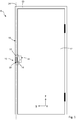
- a door system denoted as a whole by the reference number 8, is shown, which comprises a bolt locking system 10.
- the bolt locking system 10 comprises a door lock 14 arranged on a door leaf 12 of the door system 8 with a locking hook 16 and a locking device 22 arranged on a frame part 18 of a door frame 20 of the door system 8.
- the frame part 18 extends along a frame part axis 24.
- the door leaf 12 is closed relative to the door frame 20 between a position shown in the drawing Position and an open position not shown in the drawing movable, in particular pivotable.
- the drawing also shows a coordinate system which comprises mutually perpendicular axes x, y and z, the z-axis of the coordinate system corresponding to an axis that is vertical in relation to the direction of gravity.
- the frame part axis 24 runs parallel to the z-axis, ie also in the vertical direction.
- the door leaf 12 extends essentially within a plane spanned by the z-axis and a horizontal y-axis; the x-axis also runs in the horizontal direction.
- the locking device 22 comprises a fitting element 26 arranged on the frame part 18 of the door frame 20 and fastened there, and a locking element 28, cf. Figures 2 and 3 .
- the fitting element 26 has a receiving space 30 and an opening 32. This is - in the closed position of the door leaf 12 - facing the door lock 14.
- the locking element 28 has a recess 34 which at least in sections overlaps with the opening 32 of the fitting element 26.
- a locking strip 36 is provided on the side of the locking element 28 facing away from the fitting element 26; the locking element 28 is thus arranged between the fitting element 26 and the locking strip 36.
- the locking bar 36 is fastened to the frame part 18 and overlaps the locking element 28, which therefore does not detach from the fitting element 26 when viewed in the y direction.
- the locking strip 36 has a passage opening 38 which is arranged adjacent to the recess 34 of the locking element 28 and at least in sections overlaps it.
- fitting element 26 has holding sections which overlap the locking element 28, so that the locking element 28 is fastened to the fitting element 26 as seen in the y-direction.
- the locking hook 16 of the door lock 14 has a contact section 40 and a locking section 42 angled thereto, preferably perpendicular thereto.
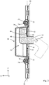
- the locking hook 16 is moved from a rest position (in Figure 2 indicated with dashed lines) about a pivot axis 41 and in a transfer plane (Y / Z plane in Figure 2 ) transferred into a locking position.
- This position of the locking hook 16 is in Figure 2 shown with solid lines.
- the locking hook 16 In the locked state, the locking hook 16 extends through the passage opening 38 of the locking bar 36 and the recess 34 of the locking element 28 and the opening 32 of the fitting element 26. The part of the locking hook 16 facing away from the locking section 42 of the door lock 14 is within the receiving space 30 of the fitting element 26 arranged. The locking hook 16 with its locking section 42 engages behind a locking surface 44 facing away from the door lock 14 of the locking element 28. This counteracts the levering out of the door leaf 12, in particular in a direction perpendicular to the contact surface between the locking section 42 and the locking surface 44 (that is, in the negative Y direction).
- the locking hook 16 with its locking section 42 completely engages behind the locking surface 44 of the locking element 28, so that the contact area between the locking section 42 and the locking surface 44 is maximized and a particularly high level of protection is ensured.
- the ideal position is when the locking element 28 and the locking hook 16 are positioned relative to one another in its locking position so that the locking hook 16 in its locking position with its contact section 40 with a contact surface 46 of the locking element 28 at an angle to the locking surface 44, preferably perpendicular Plant stands.
- the locking element 28 is mounted movably along a first movement axis 48 parallel to the frame part axis 24. In this way, deviations from the ideal position, for example as a result of the door leaf 12 being “set”, can be compensated for, and it can be ensured that the locking section 42 of the locking hook 16 always fully engages behind the locking surface 44 of the locking element 28.
- the frame part axis 24, and thus the movement axis 48 are preferably oriented vertically (cf. Figure 1 ).
- the locking hook 16 preferably swivels starting from its rest position “upwards” (that is, in the positive Z direction) into the locking position.
- the locking element 28 is in the direction of a basic position ("position 0" in Figure 4 and 5 ) is acted upon by force and is held in the unlocked state, for example with the door leaf 12 in the open position, in this basic position. From this basic position, the locking element 28 can be deflected along the first movement axis 48 and counter to the direction of application of force (that is, in the positive Z direction), but at most up to a stop position ("position 1" in FIG Figure 4 and 5 ).
- the locking hook 16 When the locking hook 16 is moved from its rest position into its locking position, the locking hook 16, before reaching its locking position, comes with its contact section 40 in contact with the contact surface 46 of the locking element 28, which is initially in its basic position.
- the locking hook 16 When the locking hook 16 is pivoted out further the locking element 28 is deflected against the direction of application of force and in the "closing direction" of the locking hook 16 (that is, in the positive Z direction) along the first movement axis 48 and, when the locking hook 16 has reached the locking position, by the locking hook 16 preferably held in an intermediate position between the basic position and the stop position.
- the locking element 28 follows the displacement of the locking hook 16, at least until it reaches its basic position.
- the locking element 28 is always held with its contact surface 46 in contact with the contact section 40 of the locking hook 16 by the force acting against the "closing direction" (that is, in the negative Z direction).
- the locking element 28 and the locking hook 16 thus remain in an ideal position relative to one another. This ensures that - even when the locking hook 16 is displaced - the locking section 42 of the locking hook 16 always fully engages behind the locking surface 44 of the locking element 28.
- the fitting element 26 has a guide device 52, which preferably has guide sections 54 which are parallel to one another and which interact with corresponding guide surfaces 56 of the locking element 28.
- the pretensioning device 50 comprises, for example, two springs 58, which are preferably designed as compression springs and which, for example, in the area of one Guide section 54 of the fitting element 26 or are arranged adjacent thereto.
- a first end of a spring 58 is supported on a support surface 59 of the fitting element 26; an opposite end of a spring 58 acts on a force-absorbing surface 61 of the locking element 28, so that this is pressed in the direction of its basic position ("position 0"), cf. Fig. 3 and 4th .
- FIG. 5 an assembly of an embodiment of a bolt locking system 10 according to the invention is shown.
- This assembly comprises on the frame part 18 of the door frame 20 fixable components, which instead of the above with reference to the Figures 1 to 4 components described can be used.
- the assembly according to Fig. 5 additionally has a detection device 60 which detects a deflection of the locking element 28 from its basic position ("position 0") into a deflected position deviating from this basic position.
- the detection device 60 is formed, for example, by a switch or a bolt switch contact.
- the detection device 60 preferably has a contact sensor 62, also referred to as a button or opener, which has a sensor surface 64. This is in contact with a contact surface 66 of the locking element 28 when the locking element 28 is in its basic position. If the locking element 28 is deflected from its basic position by the locking hook 16 during a locking process - that is, the locking element 28 is no longer in contact with the sensor surface 64 - a Signal sent to a display system and the changed locking status of the door system displayed.
- the bolt locking system 10 further comprises an adjusting device 68, cf. Figures 3 to 6 .
- This serves to set a position on the frame part side of the locking element 28 and also of the fitting element 26 relative to the locking strip 36.
- the adjustment direction runs transversely, in particular perpendicular, to the transfer plane of the locking hook 16 (that is, along an axis parallel to the X-axis of the coordinate system shown).
- the adjusting device 68 preferably comprises two eccentric elements 72 which can be rotated about a central axis 70.
- the eccentric elements 72 are arranged with an eccentric head on receptacles 73 of the locking bar 36 and are held there so as to be rotatable about the respective axes 70.
- the eccentric elements 72 each have a shaft 74, which protrudes from the eccentric head and interacts with the locking element 28 and the fitting element 26.
- the shaft 74 is spaced apart radially from the central axis 70 of the eccentric element and can be connected at its free end to a counterpart 76.
- the respective shaft 74 engages in a link-shaped material recess 78 in the fitting element 26 and interacts there with mutually parallel contact sections 80 which delimit the material recess 78.
- the respective shaft 74 becomes an eccentric element 72 transmit a force to one of the contact sections 80, so that the fitting element 26 is deflected from an initial position transversely, in particular perpendicularly, to the transfer plane of the locking hook 16.
- the distance between the contact sections 80 is slightly greater than the thickness of the shaft 74.
- the locking element 28 also has adjustment sections 82 which, in the same way as the contact sections 80 of the fitting element 26, can interact with the respective shaft 74 of the eccentric elements 72, provided the distance between the adjustment sections 82 is slightly wider than the thickness of the shaft 74.
- the locking element 28 is positively guided via the guide device 52 on the fitting element 26, so that the locking element 28 follows a deflection of the fitting element 26 transversely, in particular perpendicular, to the transfer plane of the locking hook 16.
- the distance between the adjustment sections 82 is therefore selected to be so large that they do not collide with the shaft 74 when an eccentric section 72 rotates.
- the purpose of the above-described setting of the position of the locking element 28 in its x-direction is to position the recess 34 of the locking element 28 in the x-direction so that the recess 34 is aligned with the transfer plane of the locking hook 16 and the locking hook 16 is not collides with the lateral edges of the recess 34 (with a lateral Touching the edges of the recess 34 is not preferred, but possible).
- FIGS. 6a, 6b, 6c show side views of an assembly of an embodiment of the bolt locking system 10 in different functional positions.
- the locking device 22, comprising the fitting element 26 and the locking element 28 is in a basic position relative to the locking bar 36, which is central with respect to the X-axis.
- the receiving space 30 of the fitting element 26 and the recess 34 of the locking element 28 are therefore centered with respect to the passage opening 38 of the closing strip 36 is positioned along the X-axis.
- the eccentric elements 72 of the adjusting device 68 are positioned in an initial rotational position around the eccentric axis 70 so that the respective shaft 74 is located on a central axis 84 of the locking bar 36 that is parallel to the movement axis 48 and the Z axis of the coordinate system shown.
- the two eccentric elements 72 are preferably rotated by 180 ° relative to one another.
- the locking device 22 is in a first extreme position relative to the locking strip 36.
- the fitting element 26 and the locking element 28 are in a position that is maximally deflected from their basic position in the positive X direction.
- the two eccentric elements 72 of the adjusting device 68 are here rotated from their initial rotational position, in each case in the opposite direction, by 90 ° around the eccentric axis 70, so that the respective shaft 74 is in a position spaced apart from the central axis 84 in the positive X direction.
Landscapes
- Engineering & Computer Science (AREA)
- Structural Engineering (AREA)
- Lock And Its Accessories (AREA)
Description
- Die Erfindung betrifft ein Riegelverschlusssystem, mit einem an einem Türblatt angeordneten oder anordenbaren Schloss mit einem Verriegelungshaken, mit einer Verriegelungseinrichtung, die an einem sich längs einer Rahmenteilachse erstreckenden Rahmenteil eines Türrahmens angeordnet oder anordenbar ist, wobei die Verriegelungseinrichtung ein Riegelelement aufweist, wobei der Verriegelungshaken aus einer Ruhestellung in eine Verriegelungsstellung überführbar ist und in seiner Verriegelungsstellung mit dem Riegelelement verriegelt oder verriegelbar ist.
- Solche Riegelverschlusssysteme haben sich in der Praxis zur Verriegelung von Türanlagen, beispielsweise von Flügeltüren oder Schiebetüren, etabliert. Aus der
DE 20 2011 001 547 U1 ist ein solches Riegelverschlusssystem bekannt. - Insbesondere werden Riegelverschlusssysteme mit Verriegelungshaken in Türanlagen verbaut, bei denen eine erhöhte Sicherheit, beispielsweise ein erhöhter Einbruchsschutz, gefordert ist. Dadurch, dass der Verriegelungshaken im verriegelten Zustand das rahmenseitige Riegelelement hintergreift, wird ein Aushebeln der Tür erschwert.
- Ein Riegelverschlusssystem mit den Merkmalen des Oberbegriffs des Patentanspruchs 1 ist aus der
JP 2001 342766 A - Der vorliegenden Erfindung liegt die Aufgabe zugrunde, ein Riegelverschlusssystem bereitzustellen, das eine hohe Sicherheit bei geringem Montage- und Wartungsaufwand gewährleistet.
- Diese Aufgabe wird bei einem Riegelverschlusssystem mit den Merkmalen des Oberbegriffs des Patentanspruchs 1 erfindungsgemäß durch die kennzeichnenden Merkmale des Patentanspruchs 1 gelöst.
- Erfindungsgemäß ist es möglich, dass die relative Position zwischen Verriegelungshaken und Riegelelement von einer Idealposition abweichen kann, beispielsweise in Folge einer ungenauen Montage des Türblatts relativ zum Türrahmen oder in Folge eines schwerkraftbedingten "Setzens" des Türblatts relativ zu dem Türrahmen.
- Das erfindungsgemäße Riegelverschlusssystem zeichnet sich dadurch aus, dass das Riegelelement entlang einer zu der Rahmenteilachse parallelen ersten Bewegungsachse bewegbar gelagert ist und dass das Riegelelement entlang der ersten Bewegungsachse in Richtung einer Grundstellung kraftbeaufschlagt ist. Durch die bewegbare Lagerung des Riegelelements können Abweichungen von einer Idealposition des Verriegelungshakens relativ zum Riegelelement, beispielsweise in Folge ungenauer Montage des Türblatts relativ zum Türrahmen, auf einfache Weise ausgeglichen werden, ohne dass die ganze Türanlage justiert werden muss. Das Riegelelement kann einer Verschiebung des Verriegelungshakens entlang der ersten Bewegungsachse folgen. Es kann somit stets ein möglichst vollständiges Hintergreifen des Verriegelungshakens sichergestellt werden.
- Durch die Kraftbeaufschlagung wird das Riegelelement im unverriegelten Zustand in einer Grundstellung gehalten. Dies ermöglicht es, dass der Verriegelungshaken beim Überführen in seine Verriegelungsstellung das Riegelelement hintergreifen und mit diesem verriegeln kann. Darüber hinaus wird im unverriegelten Zustand, beispielsweise bei geöffneter Tür, ein etwaiges Klappern des Riegelelements verhindert.
- Bei dem erfindungsgemäßen Riegelverschlusssystem ist somit eine aufwändige Erstmontage der ganzen Türanlage, welche eine hochgenaue Relativpositionierung von Verriegelungshaken und Riegelelement umfasst, nicht erforderlich, da etwaige Montageungenauigkeiten mittels der beweglichen Anordnung des Riegelelements kompensiert werden können.
- Es ist auch keine regelmäßige Kontrolle oder Wartung der Türanlage erforderlich, da es die bewegliche Anordnung des Riegelelements auch ermöglicht, mit der Zeit auftretende Veränderungen der Relativposition von Verriegelungshaken und Riegelelement zu kompensieren.
- Es wurde erfindungsgemäß erkannt, dass - abgesehen von Abweichungen von der Idealposition durch eine ungenaue Montage - insbesondere zeitlich verzögerte Änderungen der Relativposition des Verriegelungshakens und des Riegelelements, beispielsweise durch ein "Setzen" des Türblatts, ein erhöhtes Sicherheitsrisiko und einen hohen Wartungsaufwand darstellen. Wenn sich das Türblatt unter seinem Eigengewicht "setzt", sich also in Richtung der Schwerkraft relativ zum Türrahmen verschiebt, hat dies zur Folge, dass sich eine für eine Verriegelung wirksame Kontaktfläche zwischen dem Verriegelungshaken und dem Riegelelement mit der Zeit verändert und sich insbesondere verkleinern kann. Ein solcher Prozess des "Setzens" ist ein langsamer, schleichender Prozess, der zum Teil über Jahre andauern kann. Um stets ein vollständiges Hintergreifen des Verriegelungshakens und somit eine sichere Verriegelung der Tür zur gewährleisten, müsste das Riegelverschlusssystem kontinuierlich überprüft und neu justiert werden, was mit einem hohen Wartungsaufwand verbunden wäre. Das erfindungsgemäße Riegelverschlusssystem ermöglicht es nun, eine solche Verschiebung durch "Setzen" des Türblatts auf einfache Weise kontinuierlich auszugleichen, ohne dass dies einen Wartungsaufwand erfordert.
- Erfindungsgemäß weist der Verriegelungshaken einen Anlageabschnitt auf, welcher - entlang eines Überführungswegs des Verriegelungshakens aus seiner Ruhestellung in seine Verriegelungsstellung, vor Erreichen der Verriegelungsstellung, mit einer Anlagefläche des Riegelelements in Anlage gelangt. Dies ermöglicht eine zuverlässige Kraftübertragung von dem Verriegelungshaken auf das Riegelelement bei Überführung des Verriegelungshakens aus seiner Ruhestellung in seine Verriegelungsstellung. Der Verriegelungshaken gelangt also bereits vor Erreichen der Verriegelungsstellung mit der Anlagefläche des Riegelelements in Anlage. Hierdurch wird eine spielfreie Verbindung zwischen Riegelelement und Verriegelungshaken im Verriegelungszustand sichergestellt und somit eine besonders sichere und zuverlässige Verriegelung realisiert.
- Für eine zuverlässige Verriegelung ist es vorgesehen, dass der Verriegelungshaken einen Verriegelungsabschnitt aufweist, der zumindest in der Verriegelungsstellung des Verriegelungshakens eine Verriegelungsfläche des Riegelelements hintergreift.
- In der Verriegelungsstellung des Verriegelungshakens ist ferner das Riegelelement längs der ersten Bewegungsachse und entgegen der Kraftbeaufschlagungsrichtung aus seiner Grundstellung in eine ausgelenkte Stellung ausgelenkt. Dies ermöglicht es, Verschiebungen des Verriegelungshakens, insbesondere solche Verschiebungen, die sich im Laufe der Zeit ergeben, kontinuierlich und instantan auszugleichen und somit stets ein vollständiges Hintergreifen des Verriegelungshakens sicherzustellen. Die Grundposition von Verriegelungshaken und Riegelelement wird bei der Erstmontage der Türanlage vorzugsweise so gewählt, dass das Riegelelement in der Verriegelungsstellung des Verriegelungshaken so weit ausgelenkt ist, dass sich das Riegelelement zumindest über einen Mindestweg hinweg in Richtung seiner Grundstellung verschieben kann, wobei der Mindestweg definiert, um inwieweit eine unerwünschte Veränderung der Position des Verriegelungshakens in Kraftbeaufschlagungsrichtung des Riegelelements, beispielsweise in Folge eines "Setzens" des Türblatts, ausgeglichen oder kompensiert werden kann. Durch die Kraftbeaufschlagung wird sichergestellt, dass das Riegelelement immer in Kontakt mit dem Verriegelungshaken steht und instantan einer unerwünschten Verschiebung des Verriegelungshakens in Kraftbeaufschlagungsrichtung folgen kann.
- Erfindungsgemäß weist die Verriegelungseinrichtung eine Detektionseinrichtung auf, welche eine Auslenkung des Riegelelements aus seiner Grundstellung in eine ausgelenkte Stellung detektiert. Dies ermöglicht es, auf einfache Art und Weise von extern zu überwachen, ob der Verriegelungshaken einwandfrei mit dem Riegelelement verriegelt ist und die Tür sicher verschlossen ist. Dies ist besonders zur Überwachung von Türanlagen in sicherheitsrelevanten Einsatzbereichen von Vorteil.
- Um eine Verschiebung des Verriegelungshakens durch ein "Setzen" der Tür auszugleichen, ist es in einer weiteren Ausführungsform besonders bevorzugt, wenn die Rahmenteilachse und die erste Bewegungsachse vertikal oder zumindest näherungsweise vertikal orientiert sind. Es ist möglich, dass die Kraftbeaufschlagung des Riegelelements allein dadurch bereitgestellt ist, dass das Riegelelement ein Eigengewicht aufweist und somit dazu neigt, sich bezogen auf die Schwerkraftrichtung "nach unten" zu bewegen. Bei einer bevorzugten Ausführungsform weist die Verriegelungseinrichtung jedoch zur Kraftbeaufschlagung des Riegelelements eine Vorspanneinrichtung auf.
- Bei einer weiteren bevorzugten Ausführungsform weist die Vorspanneinrichtung mindestens eine Feder, vorzugsweise in Form einer Druckfeder oder Zugfeder, auf. Dies ermöglicht es, auf einfache, kostengünstige und zugleich zuverlässige Weise, das Riegelelement in Richtung seiner Grundstellung vorzuspannen.
- Ferner ist bevorzugt, wenn die Verriegelungseinrichtung eine Führungseinrichtung zur Führung des Riegelelements längs der ersten Bewegungsachse aufweist. Hierdurch wird sichergestellt, dass sich das Riegelelement zumindest vornehmlich entlang der vorgegebenen Achse bewegt und dass sich das Riegelelement entlang seines Bewegungswegs nicht verkantet. Auch hierdurch wird eine besonders sichere und zuverlässige Funktion des Riegelverschlusssystems gewährleistet.
- Bevorzugt weist die Detektionseinrichtung mindestens einen Kontaktsensor auf, welcher mindestens eine Sensorfläche aufweist, die in Kontakt mit mindestens einer Kontaktfläche des Riegelelements steht, wenn sich das Riegelelement in seiner Grundstellung befindet. Mit einer solchen Anordnung kann eine Auslenkung des Riegelelements aus seiner Grundstellung auf besonders zuverlässige und robuste Weise detektiert wird.
- Bei einer weiteren bevorzugten Ausführungsform ist eine an dem Rahmenteil befestigte oder befestigbare Schließleiste vorgesehen, welche vorzugsweise unmittelbar benachbart zu dem Riegelelement angeordnet ist. Eine solche Schließleiste, auch als Schließplatte bezeichnet, kann als Metallblech ausgeführt sein und bietet zusätzlichen Schutz gegen ein Aushebeln der Tür. Die Schließleiste weist vorzugsweise eine Durchtrittsöffnung auf, in die der Verriegelungshaken in seiner Verriegelungsstellung eingreift. Bevorzugt ist das Riegelelement unmittelbar benachbart zu einer solchen Durchtrittsöffnung der Schließleiste angeordnet, so dass der Verriegelungshaken durch die Durchtrittsöffnung hindurch in seine Verriegelungsstellung verlagerbar und mit dem Riegelelement verriegelbar ist.
- Eine weitere bevorzugte Ausführungsform sieht eine Einstelleinrichtung vor, mittels welcher eine rahmenteilseitige Position des Riegelelements quer, insbesondere senkrecht, zu einer Überführungsebene des Verriegelungshakens, in welcher der Verriegelungshaken aus der Ruhestellung in die Verriegelungsstellung überführbar ist, einstellbar ist. Abweichungen von einer vorgegebenen Relativlage zwischen dem Riegelelement und dem Verriegelungshaken in einer Richtung quer zur Überführungsebene des Verriegelungshakens können beispielsweise durch den Einsatz von unterschiedlichen Profilsystemen oder Gummidichtungen entstehen. Durch die Einstelleinrichtung wird es auf einfache Weise ermöglicht, solche Abweichungen auszugleichen und eine Sollposition des Riegelelements relativ zu dem Rahmenteil vorzugeben, um ein einwandfreies Eingreifen des Verriegelungshakens in die Verriegelungseinrichtung, und somit ein sicheres Verriegeln der Tür, zu gewährleisten. Auf diese Weise kann das Riegelverschlusssystem bei geringem Montageaufwand variabel an verschiedene Türanlagen angepasst werden.
- Bei einer weiteren bevorzugten Ausführungsform weist die Einstelleinrichtung mindestens ein um eine Exzenterachse verdrehbares Exzenterelement auf. Im Zuge einer Drehung des mindestens einen Exzenterelements kann die Position des Riegelelements quer zu der Überführungsebene des Verriegelungshakens auf besonders einfache Weise eingestellt werden. Es ist somit auch nach Einbau des Riegelverschlusssystems ohne großen Montageaufwand möglich, eine relative Verschiebung des Riegelelements und des Verriegelungshakens in einer Richtung quer zur Überführungsebene des Verriegelungshakens auszugleichen. Bei einer weiteren bevorzugten Ausführungsform ist ein am Rahmenteil des Türrahmens angeordnetes oder anordenbares Beschlagelement vorgesehen, das einen Aufnahmeraum aufweist, in welchen der Verriegelungshaken zumindest in seiner Verriegelungsstellung eingreift, und/oder welches unmittelbar benachbart zu dem Riegelelement angeordnet ist und/oder an welchem die vorstehend beschriebene Vorspanneinrichtung, die vorstehend beschriebene Führungseinrichtung, die vorstehend beschriebene Detektionseinrichtung und/oder die vorstehend beschriebene Einstelleinrichtung angeordnet ist oder sind.
- Die Erfindung betrifft ferner eine Türanlage, mit einem Türblatt, einem Türrahmen und mindestens einem vorstehend beschriebenen Riegelverschlusssystem, wobei das Schloss an dem Türblatt und die Verriegelungseinrichtung an einem sich längs einer Rahmenteilachse erstreckenden Rahmenteil des Türrahmens angeordnet ist.
- Weitere Merkmale und Vorteile der Erfindung sind Gegenstand der nachfolgenden Beschreibung und der zeichnerischen Darstellung eines bevorzugten Ausführungsbeispiels.
- In der Zeichnung zeigt
- Fig. 1
- eine Vorderansicht einer nicht alle Merkmale der Erfindung umfassenden Ausführungsform einer Türanlage mit einem Riegelverschlusssystem;
- Fig. 2
- einen in
Fig. 1 mit II bezeichneten Ausschnitt in vergrößerter Darstellung und längs einer vertikalen Schnittebene; - Fig. 3
- eine perspektivische Explosionsdarstellung des Riegelverschlusssystems gemäß
Fig. 1 undFig. 2 ; - Fig. 4
- eine Seitenansicht einer Baugruppe einer weiteren Ausführungsform mit Teilen eines erfindungsgemäßen Riegelverschlusssystems;
- Fig. 5
- eine perspektivische Darstellung einer erfindungsgemäßen Ausführungsform einer Baugruppe eines Riegelverschlusssystems; und
- Fig. 6a, 6b, 6c
- Seitenansichten einer Baugruppe der Riegelverschlusssysteme gemäß
Fig. 1 bis 3 in verschiedenen Funktionsstellungen. - In
Figur 1 ist eine insgesamt mit dem Bezugszeichen 8 bezeichnete Türanlage dargestellt, die ein Riegelverschlusssystem 10 umfasst. Das Riegelverschlusssystem 10 umfasst ein an einem Türblatt 12 der Türanlage 8 angeordnetes Türschloss 14 mit einem Verriegelungshaken 16 und eine an einem Rahmenteil 18 eines Türrahmens 20 der Türanlage 8 angeordnete Verriegelungseinrichtung 22. Das Rahmenteil 18 erstreckt sich hierbei längs einer Rahmenteilachse 24. - Das Türblatt 12 ist zwischen einer in der Zeichnung dargestellten, relativ zu dem Türrahmen 20 geschlossenen Stellung und einer in der Zeichnung nicht dargestellten offenen Stellung bewegbar, insbesondere verschwenkbar.
- In der Zeichnung ist auch ein Koordinatensystem gezeigt, welches zueinander senkrechte Achsen x, y und z umfasst, wobei die z-Achse des Koordinatensystems einer bezogen auf die Schwerkraftrichtung vertikalen Achse entspricht. Die Rahmenteilachse 24 verläuft parallel zu der z-Achse, also auch in vertikaler Richtung. Das Türblatt 12 erstreckt sich im Wesentlichen innerhalb einer durch die z-Achse und durch eine horizontale y-Achse aufgespannte Ebene; die x-Achse verläuft ebenfalls in horizontaler Richtung.
- Die Verriegelungseinrichtung 22 umfasst ein am Rahmenteil 18 des Türrahmens 20 angeordnetes und dort befestigtes Beschlagelement 26 und ein Riegelelement 28, vgl.
Figuren 2 und3 . Das Beschlagelement 26 weist einen Aufnahmeraum 30 und eine Öffnung 32 auf. Diese ist - in der geschlossenen Stellung des Türblatts 12 - dem Türschloss 14 zugewandt. Das Riegelelement 28 weist eine Aussparung 34 auf, die zumindest abschnittsweise mit der Öffnung 32 des Beschlagelements 26 überlappt. Auf der dem Beschlagelement 26 abgewandten Seite des Riegelelements 28 ist eine Schließleiste 36 vorgesehen; das Riegelelement 28 ist also zwischen dem Beschlagelement 26 und der Schließleiste 36 angeordnet. Die Schließleiste 36 ist an dem Rahmenteil 18 befestigt und überfängt das Riegelelement 28, welches sich somit in y-Richtung gesehen nicht von dem Beschlagelement 26 löst. - Die Schließleiste 36 weist eine Durchtrittsöffnung 38 auf, die benachbart zu der Aussparung 34 des Riegelelements 28 angeordnet ist und zumindest abschnittsweise mit dieser überlappt.
- Es ist möglich, dass keine Schließleiste 36 vorgesehen ist. In diesem Fall ist es bevorzugt, wenn das Beschlagelement 26 Halteabschnitte aufweist, welche das Riegelelement 28 übergreifen, so dass das Riegelelement 28 in y-Richtung gesehen an dem Beschlagelement 26 befestigt ist.
- Der Verriegelungshaken 16 des Türschlosses 14 weist einen Anlageabschnitt 40 und einen hierzu winkligen, vorzugsweise senkrechten Verriegelungsabschnitt 42 auf. Der Verriegelungshaken 16 wird beim Verriegeln des Türschlosses 14 aus einer Ruhestellung (in
Figur 2 mit gestrichelten Linien angedeutet) um eine Schwenkachse 41 und in einer Überführungsebene (Y/Z-Ebene inFigur 2 ) in eine Verriegelungsstellung überführt. Diese Position des Verriegelungshakens 16 ist inFigur 2 mit durchgezogenen Linien dargestellt. - Im verriegelten Zustand durchgreift der Verriegelungshaken 16 die Durchtrittsöffnung 38 der Schließleiste 36 und die Aussparung 34 des Riegelelements 28 und die Öffnung 32 des Beschlagelements 26. Der ausgehend von dem Verriegelungsabschnitt 42 dem Türschloss 14 abgewandte Teil des Verriegelungshakens 16 ist innerhalb des Aufnahmeraums 30 des Beschlagelements 26 angeordnet. Dabei hintergreift der Verriegelungshaken 16 mit seinem Verriegelungsabschnitt 42 eine dem Türschloss 14 abgewandte Verriegelungsfläche 44 des Riegelelements 28. Somit wird einem Aushebeln des Türblatts 12 entgegengewirkt, insbesondere in einer Richtung senkrecht zur Kontaktfläche zwischen Verriegelungsabschnitt 42 und Verriegelungsfläche 44 (also in negativer Y-Richtung).
- In einer Idealposition hintergreift der Verriegelungshaken 16 mit seinem Verriegelungsabschnitt 42 die Verriegelungsfläche 44 des Riegelelements 28 vollständig, sodass die Kontaktfläche zwischen Verriegelungsabschnitt 42 und Verriegelungsfläche 44 maximiert ist und ein besonders hoher Schutz gewährleistet ist. Die Idealposition liegt dann vor, wenn das Riegelelement 28 und der Verriegelungshaken 16 in dessen Verriegelungsstellung so relativ zueinander positioniert sind, dass der Verriegelungshaken 16 in seiner Verriegelungsstellung mit seinem Anlageabschnitt 40 mit einer zu der Verriegelungsfläche 44 winkligen, vorzugsweise senkrechten Anlagefläche 46 des Riegelelements 28 in Anlage steht.
- Das Riegelelement 28 ist entlang einer zu der Rahmenteilachse 24 parallelen ersten Bewegungsachse 48 bewegbar gelagert. Dadurch können Abweichungen von der Idealposition, zum Beispiel in Folge eines "Setzens" des Türblatts 12, ausgeglichen werden, und es kann sichergestellt werden, dass der Verriegelungsabschnitt 42 des Verriegelungshakens 16 die Verriegelungsfläche 44 des Riegelelements 28 stets vollständig hintergreift.
- Um insbesondere solche Verschiebungen auszugleichen, die durch ein "Setzen" des Türblatts in Richtung der Schwerkraft "nach unten" (also in negativer z-Richtung) entstehen können, sind die Rahmenteilachse 24, und somit die Bewegungsachse 48, vorzugsweise vertikal ausgerichtet (vergleiche
Figur 1 ). Der Verriegelungshaken 16 schwenkt dabei vorzugsweise ausgehend von seiner Ruhestellung "nach oben" (also in positiver Z-Richtung) in die Verriegelungsstellung aus. - Das Riegelelement 28 ist mittels einer Vorspanneinrichtung 50 in Richtung einer Grundstellung ("Position 0" in
Figur 4 und5 ) kraftbeaufschlagt und wird im unverriegelten Zustand, beispielsweise bei geöffneter Stellung des Türblatts 12, in dieser Grundstellung gehalten. Von dieser Grundstellung aus ist das Riegelelement 28 entlang der ersten Bewegungsachse 48 und entgegen der Kraftbeaufschlagungsrichtung (also in positiver Z-Richtung) auslenkbar, maximal jedoch bis zu einer Stoppstellung ("Position 1" inFigur 4 und5 ). - Bei der Überführung des Verriegelungshakens 16 aus seiner Ruhestellung in seine Verriegelungsstellung gelangt der Verriegelungshaken 16, vor Erreichen seiner Verriegelungsstellung, mit seinem Anlageabschnitt 40 in Anlage mit der Anlagefläche 46 des, zunächst in seiner Grundstellung befindlichen, Riegelelements 28. Bei weiterem Ausschwenken des Verriegelungshakens 16 wird das Riegelelement 28 entgegen der Kraftbeaufschlagungsrichtung und in "Schließrichtung" des Verriegelungshakens 16 (also in positiver Z-Richtung) entlang der ersten Bewegungsachse 48 ausgelenkt und, bei Erreichen der Verriegelungsstellung des Verriegelungshakens 16, durch den Verriegelungshaken 16 vorzugsweise in einer Zwischenposition zwischen der Grundstellung und der Stoppstellung gehalten.
- Im Falle einer Verschiebung des Verriegelungshakens 16 in einer der "Schließrichtung" entgegengesetzten Richtung (also in negativer Z-Richtung), welche Verschiebung die Kontaktfläche zwischen dem Verriegelungshaken 16 und dem Riegelelement 28 verringern würde, folgt das Riegelelement 28 der Verschiebung des Verriegelungshakens 16, zumindest bis zum Erreichen seiner Grundstellung. Das Riegelelement 28 wird durch die entgegen der "Schließrichtung" (also in negativer Z-Richtung) wirkende Kraftbeaufschlagung stets mit seiner Anlagefläche 46 in Kontakt mit dem Anlageabschnitt 40 des Verriegelungshakens 16 gehalten. Das Riegelelement 28 und der Verriegelungshaken 16 verbleiben somit relativ zueinander in einer Idealposition. Dadurch wird gewährleistet, dass - auch bei einer Verschiebung des Verriegelungshakens 16 - der Verriegelungsabschnitt 42 des Verriegelungshakens 16 stets vollständig die Verriegelungsfläche 44 des Riegelelements 28 hintergreift.
- Zur Führung des Riegelelements 28 entlang der ersten Bewegungsachse 48 weist das Beschlagelement 26 eine Führungseinrichtung 52 auf, welche vorzugsweise zueinander parallele Führungsabschnitte 54 aufweist, die mit korrespondierenden Führungsflächen 56 des Riegelelements 28 zusammenwirken.
- Die Vorspanneinrichtung 50 umfasst beispielsweise zwei Federn 58, die vorzugsweise als Druckfedern ausgebildet sind und die beispielsweise im Bereich eines Führungsabschnitts 54 des Beschlagelements 26 oder hierzu benachbart angeordnet sind. Ein erstes Ende einer Feder 58 stützt sich an einer Abstützfläche 59 des Beschlagelements 26 ab; ein gegenüberliegendes Ende einer Feder 58 beaufschlagt eine Kraftaufnahmefläche 61 des Riegelelements 28, sodass dieses in Richtung seiner Grundstellung ("Position 0") gedrückt wird, vgl.
Fig. 3 und4 . - In der
Figur 5 ist eine Baugruppe einer erfindungsgemäßen Ausführungsform eines Riegelverschlusssystems 10 dargestellt. Diese Baugruppe umfasst an dem Rahmenteil 18 des Türrahmens 20 festlegbare Bauteile, welche anstelle der vorstehend unter Bezugnahme auf dieFiguren 1 bis 4 beschriebenen Bauteile verwendet werden können. Die Baugruppe gemäßFig. 5 weist zusätzlich eine Detektionseinrichtung 60 auf, welche eine Auslenkung des Riegelelements 28 aus seiner Grundstellung ("Position 0") in eine von dieser Grundstellung abweichende, ausgelenkte Stellung detektiert. - Die Detektionseinrichtung 60 ist beispielsweise durch einen Schalter oder einen Riegel-Schalt-Kontakt gebildet. Die Detektionseinrichtung 60 weist vorzugsweise einen Kontaktsensor 62, auch als Taster oder Öffner bezeichnet, auf, der eine Sensorfläche 64 aufweist. Diese steht in Kontakt mit einer Kontaktfläche 66 des Riegelelements 28, wenn sich das Riegelelement 28 in seiner Grundstellung befindet. Wird bei einem Verriegelungsvorgang das Riegelelement 28 durch den Verrieglungshaken 16 aus seiner Grundstellung ausgelenkt - steht das Riegelelement 28 also nicht mehr in Kontakt mit der Sensorfläche 64 - so wird ein Signal an ein Anzeigesystem gesendet und der geänderte Verriegelungszustand der Türanlage angezeigt.
- Das Riegelverschlusssystem 10 umfasst ferner eine Einstelleinrichtung 68, vgl.
Figuren 3 bis 6 . Diese dient dazu, eine rahmenteilseitige Position der des Riegelelements 28 und auch des Beschlagelements 26 relativ zu der Schließleiste 36 einzustellen. Die Einstellrichtung verläuft quer, insbesondere senkrecht, zu der Überführungsebene des Verriegelungshakens 16 (also entlang einer Achse parallel zur X-Achse des gezeigten Koordinatensystems). - Die Einstelleinrichtung 68 umfasst vorzugsweise zwei um eine zentrale Achse 70 verdrehbare Exzenterelemente 72. Die Exzenterelemente 72 sind mit einem Exzenterkopf an Aufnahmen 73 der Schließleiste 36 angeordnet und dort um die jeweiligen Achsen 70 verdrehbar gehalten. Die Exzenterelemente 72 weisen jeweils einen Schaft 74 auf, der von dem Exzenterkopf abragt und mit dem Riegelelement 28 und dem Beschlagelement 26 zusammenwirkt. Der Schaft 74 ist zu der zentralen Achse 70 des Exzenterelements radial beabstandet und an seinem freien Ende mit einem Gegenstück 76 verbindbar.
- Der jeweilige Schaft 74 greift in eine kulissenförmige Materialaussparung 78 des Beschlagelements 26 ein und wirkt dort mit zueinander parallelen Kontaktabschnitten 80, welche die Materialaussparung 78 begrenzen, zusammen. Bei einer Drehung der Exzenterelemente 72 um die zentrale Achse 70 wird vom jeweiligen Schaft 74 eines Exzenterlements 72 eine Kraft auf einen der Kontaktabschnitte 80 übertragen, so dass das Beschlagelement 26 aus einer Ausgangsstellung quer, insbesondere senkrecht, zu der Überführungsebene des Verriegelungshakens 16 ausgelenkt wird. Der Abstand der Kontaktabschnitte 80 ist geringfügig größer als die Dicke des Schafts 74.
- Das Riegelelement 28 weist ebenfalls Einstellabschnitte 82 auf, welche in gleicher Weise wie die Kontaktabschnitte 80 des Beschlagelements 26 mit dem jeweiligen Schaft 74 der Exzenterelemente 72 zusammenwirken können, sofern der Abstand der Einstellabschnitte 82 geringfügig breiter ist als die Dicke des Schafts 74.
- In dem in der Zeichnung dargestelllten Ausführungsbeispiel ist das Riegelelement 28 über die Führungseinrichtung 52 an dem Beschlagelement 26 zwangsgeführt, so dass das Riegelelement 28 einer Auslenkung des Beschlagelements 26 quer, insbesondere senkrecht, zu der Überführungsebene des Verriegelungshakens 16 folgt. Daher ist der Abstand der Einstellabschnitte 82 so groß gewählt, dass diese bei einer Drehung eines Exzenterabschnitts 72 nicht mit dem Schaft 74 kollidieren.
- Der Zweck der vorstehend beschriebenen Einstellung der Position des Riegelelements 28 in dessen x-Richtung besteht darin, die Aussparung 34 des Riegelelements 28 in x-Richtung so zu positionieren, dass die Aussparung 34 mit der Überführungsebene des Verriegelungshakens 16 fluchtet und der Verriegelungshaken 16 nicht mit den seitlichen Rändern der Aussparung 34 kollidiert (wobei ein seitliches Berühren der Ränder der Aussparung 34 zwar nicht bevorzugt, aber möglich ist).
- Die
Figuren 6a, 6b, 6c zeigen Seitenansichten einer Baugruppe einer Ausführungsform des Riegelverschlusssystems 10 in verschiedenen Funktionsstellungen. InFigur 6a befindet sich die Verriegelungseinrichtung 22, umfassend das Beschlagelement 26 und das Riegelelement 28, in einer bezogen auf die X-Achse mittigen Grundstellung relativ zu der Schließleiste 36. Der Aufnahmeraum 30 des Beschlagelements 26 und die Aussparung 34 des Riegelelements 28 sind also mittig in Bezug auf die Durchtrittsöffnung 38 der Schließleiste 36 entlang der X-Achse positioniert. Die Exzenterelemente 72 der Einstelleinrichtung 68 sind hierbei in einer Ausgangsdrehlage um die Exzenterachse 70 positioniert, so dass sich der jeweilige Schaft 74 auf einer, zur Bewegungsachse 48 und zur Z-Achse des gezeigten Koordinatensystems parallelen, Mittenachse 84 der Schließleiste 36 befindet. Vorzugsweise sind die beiden Exzenterelemente 72 relativ zueinander um 180° verdreht. - In
Figur 6b befindet sich die Verriegelungseinrichtung 22 in einer ersten Extremstellung relativ zur Schließleiste 36. In dieser ersten Extremstellung befinden sich das Beschlagelement 26 und das Riegelelement 28 in einer aus ihrer Grundstellung in positiver X-Richtung maximal ausgelenkten Position. Die beiden Exzenterelemente 72 der Einstelleinrichtung 68 sind hierbei aus ihrer Ausgangsdrehlage, in jeweils entgegengesetzter Richtung, um jeweils 90° um die Exzenterachse 70 gedreht, so dass sich der jeweilige Schaft 74 in einer zur Mittenachse 84 in positiver X-Richtung beabstandeten Position befindet. - In
Figur 6c befinden sich das Beschlagelement 26 und das Riegelelement 28 in ihrer zweiten, zur ersten Extremstellung entgegengesetzten Extremstellung.
Claims (12)
- Riegelverschlusssystem (10), mit einem an einem Türblatt (12) angeordneten oder anordenbaren Schloss (14) mit einem Verriegelungshaken (16), mit einer Verriegelungseinrichtung (22), die an einem sich längs einer Rahmenteilachse (24) erstreckenden Rahmenteil (18) eines Türrahmens (20) angeordnet oder anordenbar ist, wobei die Verriegelungseinrichtung (22) ein Riegelelement (28) aufweist, wobei der Verriegelungshaken (16) aus einer Ruhestellung in eine Verriegelungsstellung überführbar ist und in seiner Verriegelungsstellung mit dem Riegelelement (28) verriegelt ist, wobei das Riegelelement (28) entlang einer zu der Rahmenteilachse (24) parallelen ersten Bewegungsachse (48) bewegbar gelagert ist und wobei das Riegelelement (28) entlang der ersten Bewegungsachse (48) in Richtung einer Grundstellung kraftbeaufschlagt ist, wobei der Verriegelungshaken (16) einen Verriegelungsabschnitt (42) aufweist, der zumindest in der Verriegelungsstellung des Verriegelungshakens (16) eine Verriegelungsfläche (44) des Riegelelements (28) hintergreift, wobei der Verriegelungshaken (16) einen Anlageabschnitt (40) aufweist, welcher - entlang eines Überführungswegs des Verriegelungshakens (16) aus seiner Ruhestellung in seine Verriegelungsstellung, vor Erreichen der Verriegelungsstellung, mit einer Anlagefläche (46) des Riegelelements (28) in Anlage gelangt, dadurch gekennzeichnet, dass die Verriegelungseinrichtung (22) eine Detektionseinrichtung (60) aufweist, welche eine Auslenkung des Riegelelements (28) aus seiner Grundstellung in eine ausgelenkte Stellung detektiert.
- Riegelverschlusssystem (10) nach Anspruch 1, dadurch gekennzeichnet, dass, in der Verriegelungsstellung des Verriegelungshakens (16), das Riegelelement (28) längs der ersten Bewegungsachse (48) und entgegen der Kraftbeaufschlagungsrichtung aus seiner Grundstellung in eine ausgelenkte Stellung ausgelenkt ist.
- Riegelverschlusssystem (10) nach einem der voranstehenden Ansprüche, dadurch gekennzeichnet, dass die Rahmenteilachse (24) und die erste Bewegungsachse (48) vertikal oder zumindest näherungsweise vertikal orientiert sind.
- Riegelverschlusssystem (10) nach einem der voranstehenden Ansprüche, dadurch gekennzeichnet, dass die Verriegelungseinrichtung (22) zur Kraftbeaufschlagung des Riegelelements (28) eine Vorspanneinrichtung (50) aufweist.
- Riegelverschlusssystem (10) nach Anspruch 5, dadurch gekennzeichnet, dass die Vorspanneinrichtung (50) mindestens eine Feder (58), vorzugsweise in Form einer Druckfeder oder Zugfeder, aufweist.
- Riegelverschlusssystem (10) nach einem der voranstehenden Ansprüche, dadurch gekennzeichnet, dass die Verriegelungseinrichtung (22) eine Führungseinrichtung (52) zur Führung des Riegelelements (28) längs der ersten Bewegungsachse (48) aufweist.
- Riegelverschlusssystem (10) nach einem der voranstehenden Ansprüche, dadurch gekennzeichnet, dass die Detektionseinrichtung (60) mindestens einen Kontaktsensor (62) aufweist, welcher mindestens eine Sensorfläche (64) aufweist, die in Kontakt mit mindestens einer Kontaktfläche (66) des Riegelelements (28) steht, wenn sich das Riegelelement (28) in seiner Grundstellung befindet.
- Riegelverschlusssystem (10) nach einem der voranstehenden Ansprüche, dadurch gekennzeichnet, dass eine an dem Rahmenteil (18) befestigte oder befestigbare Schließleiste (36) vorgesehen ist, welche vorzugsweise unmittelbar benachbart zu dem Riegelelement (28) angeordnet ist.
- Riegelverschlusssystem (10) nach einem der voranstehenden Ansprüche, dadurch gekennzeichnet, dass eine Einstelleinrichtung (68) vorgesehen ist, mittels welcher eine rahmenteilseitige Position des Riegelelements (28) quer, insbesondere senkrecht, zu einer Überführungsebene des Verriegelungshakens (16), in welcher der Verriegelungshaken (16) aus der Ruhestellung in die Verriegelungsstellung überführbar ist, einstellbar ist.
- Riegelverschlusssystem (10) nach Anspruch 9, dadurch gekennzeichnet, dass die Einstelleinrichtung (68) mindestens ein um eine Exzenterachse (70) verdrehbares Exzenterelement (72) aufweist.
- Riegelverschlusssystem (10) nach einem der voranstehenden Ansprüche, gekennzeichnet durch ein am Rahmenteil (18) des Türrahmens (20) angeordnetes oder anordenbares Beschlagelement (26), das einen Aufnahmeraum (30) aufweist, in welchen der Verriegelungshaken (16) zumindest in seiner Verriegelungsstellung eingreift, und/oder welches unmittelbar benachbart zu dem Riegelelement (28) angeordnet ist und/oder an welchem die Vorspanneinrichtung (50) gemäß Anspruch 4 angeordnet ist und/oder an welchem die Führungseinrichtung (52) gemäß Anspruch 6 angeordnet ist und/oder an welchem die Detektionseinrichtung (60) gemäß Anspruch 7 angeordnet ist und/oder an welchem die Einstelleinrichtung (68) gemäß Anspruch 9 angeordnet ist.
- Türanlage (8), mit einem Türblatt (12), einem Türrahmen (20) und mindestens einem Riegelverschlusssystem (10) gemäß einem der voranstehenden Ansprüche, wobei das Schloss (14) an dem Türblatt (12) und die Verriegelungseinrichtung (22) an einem sich längs einer Rahmenteilachse (24) erstreckenden Rahmenteil (18) des Türrahmens (20) angeordnet ist.
Priority Applications (1)
| Application Number | Priority Date | Filing Date | Title |
|---|---|---|---|
| EP18156788.4A EP3527757B1 (de) | 2018-02-14 | 2018-02-14 | Riegelverschlusssystem und türanlage |
Applications Claiming Priority (1)
| Application Number | Priority Date | Filing Date | Title |
|---|---|---|---|
| EP18156788.4A EP3527757B1 (de) | 2018-02-14 | 2018-02-14 | Riegelverschlusssystem und türanlage |
Publications (2)
| Publication Number | Publication Date |
|---|---|
| EP3527757A1 EP3527757A1 (de) | 2019-08-21 |
| EP3527757B1 true EP3527757B1 (de) | 2020-11-11 |
Family
ID=61223850
Family Applications (1)
| Application Number | Title | Priority Date | Filing Date |
|---|---|---|---|
| EP18156788.4A Active EP3527757B1 (de) | 2018-02-14 | 2018-02-14 | Riegelverschlusssystem und türanlage |
Country Status (1)
| Country | Link |
|---|---|
| EP (1) | EP3527757B1 (de) |
Family Cites Families (12)
| Publication number | Priority date | Publication date | Assignee | Title |
|---|---|---|---|---|
| US1625371A (en) * | 1925-12-08 | 1927-04-19 | Herman F Hoffman | Lock-actuated switch |
| GB793453A (en) * | 1955-03-25 | 1958-04-16 | Matthew Harvey And Company Ltd | Improvements relating to locking gear for doors |
| JPS542594U (de) * | 1977-06-03 | 1979-01-09 | ||
| JPS5972365A (ja) * | 1982-10-18 | 1984-04-24 | 国産金属工業株式会社 | 鎌錠の受座装置 |
| JP2700445B2 (ja) * | 1995-05-25 | 1998-01-21 | タキゲン製造株式会社 | グレーチング蓋用施錠装置の受金ユニット |
| JP4198864B2 (ja) * | 2000-04-28 | 2008-12-17 | 美和ロック株式会社 | 引き違い戸の鎌錠装置 |
| JP4235346B2 (ja) * | 2000-06-01 | 2009-03-11 | 美和ロック株式会社 | 引戸用鎌錠のストライク |
| JP4043182B2 (ja) * | 2000-09-27 | 2008-02-06 | 美和ロック株式会社 | 鎌錠用受金具のガタツキ防止機構 |
| AT8354U1 (de) * | 2005-01-14 | 2006-06-15 | Kaba Gmbh | Schliessstückanordnung |
| DE202010000212U1 (de) | 2010-02-17 | 2010-04-22 | Lemay Bv | Sicherungsvorrichtung |
| WO2012137230A1 (en) * | 2011-04-08 | 2012-10-11 | Cisa S.P.A. | Adjustable strike plate for locks |
| DE102013101033A1 (de) * | 2013-02-01 | 2014-08-07 | Carl Fuhr Gmbh & Co. Kg | Riegelaufnahmeteil |
-
2018
- 2018-02-14 EP EP18156788.4A patent/EP3527757B1/de active Active
Non-Patent Citations (1)
| Title |
|---|
| None * |
Also Published As
| Publication number | Publication date |
|---|---|
| EP3527757A1 (de) | 2019-08-21 |
Similar Documents
| Publication | Publication Date | Title |
|---|---|---|
| EP2211004B1 (de) | Verriegelungseinrichtung | |
| EP3973126B1 (de) | Möbelbeschlag | |
| EP2873792B1 (de) | Türband | |
| EP4112854A1 (de) | Beschlaganordnung | |
| EP3572605A1 (de) | Scharnieranordnung für ein schaltschrankgehäuse und ein entsprechendes schaltschrankgehäuse | |
| EP3271538A1 (de) | Tür- oder fensterscharnier | |
| EP3556978A1 (de) | Vorrichtung zur bewegung eines an einem möbelkorpus eines möbels aufgenommenen möbelteils | |
| EP2956605B1 (de) | Selbstverriegelnde schliessvorrichtung mit einem mehrfachverriegelungsantrieb | |
| DE202005015166U1 (de) | Schwenkschiebetür für Fahrzeuge, insbesondere Fahrgasttür für Fahrzeuge des öffentlichen Personennahverkehrs | |
| EP3667010B1 (de) | Anschlagvorrichtung für eine automatische türdichtung, insbesondere für eine pivot- oder pendeltür, anordnung aus einer automatischen türdichtung und einer anschlagvorrichtung | |
| EP3022723B1 (de) | Einrichtung zur überwachung der riegelposition einer schliessvorrichtung | |
| EP3118404B1 (de) | Rollenband, insbesondere für kunststofftüren und kunststofffenster | |
| EP1024238A2 (de) | Vorrichtung zum Erfassen der Stellung eines Schlossriegels | |
| EP3348773B1 (de) | Anordnung zum öffnen, schliessen und verriegeln von lamellen einer lamellenkonstruktion | |
| DE3345814C2 (de) | ||
| EP3527757A1 (de) | Riegelverschlusssystem und türanlage | |
| DE102019109642A1 (de) | Betätigungsgetriebe für ein hebe-schiebeelement mit arretierbarem betätigungshebel sowie mit solch einem betätigungsgetriebe ausgestattetes hebe-schiebeelement | |
| EP3771793B1 (de) | Beschlag für eine schiebetür | |
| DE19526016A1 (de) | Exzenterverstelleinrichtung für einen Beschlag für Fenster, Türen oder dergleichen | |
| DE20105251U1 (de) | Fehlbedienungssicherung | |
| EP2148028B1 (de) | Riegeleinrichtung für Türen | |
| EP4336007B1 (de) | Beschlag für eine schiebetür sowie schiebetür | |
| EP3101207B1 (de) | Schiebetüranordnung | |
| DE29600891U1 (de) | Sicherungseinrichtung | |
| EP3623558B1 (de) | Deckelbeschlag zum schwenkbaren befestigen eines deckels an einem möbelkorpus |
Legal Events
| Date | Code | Title | Description |
|---|---|---|---|
| PUAI | Public reference made under article 153(3) epc to a published international application that has entered the european phase |
Free format text: ORIGINAL CODE: 0009012 |
|
| STAA | Information on the status of an ep patent application or granted ep patent |
Free format text: STATUS: THE APPLICATION HAS BEEN PUBLISHED |
|
| AK | Designated contracting states |
Kind code of ref document: A1 Designated state(s): AL AT BE BG CH CY CZ DE DK EE ES FI FR GB GR HR HU IE IS IT LI LT LU LV MC MK MT NL NO PL PT RO RS SE SI SK SM TR |
|
| AX | Request for extension of the european patent |
Extension state: BA ME |
|
| STAA | Information on the status of an ep patent application or granted ep patent |
Free format text: STATUS: REQUEST FOR EXAMINATION WAS MADE |
|
| 17P | Request for examination filed |
Effective date: 20200211 |
|
| RBV | Designated contracting states (corrected) |
Designated state(s): AL AT BE BG CH CY CZ DE DK EE ES FI FR GB GR HR HU IE IS IT LI LT LU LV MC MK MT NL NO PL PT RO RS SE SI SK SM TR |
|
| RIC1 | Information provided on ipc code assigned before grant |
Ipc: E05B 63/24 20060101ALI20200415BHEP Ipc: E05B 45/08 20060101AFI20200415BHEP Ipc: E05B 15/02 20060101ALI20200415BHEP |
|
| GRAP | Despatch of communication of intention to grant a patent |
Free format text: ORIGINAL CODE: EPIDOSNIGR1 |
|
| STAA | Information on the status of an ep patent application or granted ep patent |
Free format text: STATUS: GRANT OF PATENT IS INTENDED |
|
| INTG | Intention to grant announced |
Effective date: 20200528 |
|
| GRAS | Grant fee paid |
Free format text: ORIGINAL CODE: EPIDOSNIGR3 |
|
| GRAA | (expected) grant |
Free format text: ORIGINAL CODE: 0009210 |
|
| STAA | Information on the status of an ep patent application or granted ep patent |
Free format text: STATUS: THE PATENT HAS BEEN GRANTED |
|
| AK | Designated contracting states |
Kind code of ref document: B1 Designated state(s): AL AT BE BG CH CY CZ DE DK EE ES FI FR GB GR HR HU IE IS IT LI LT LU LV MC MK MT NL NO PL PT RO RS SE SI SK SM TR |
|
| REG | Reference to a national code |
Ref country code: GB Ref legal event code: FG4D Free format text: NOT ENGLISH |
|
| REG | Reference to a national code |
Ref country code: CH Ref legal event code: NV Representative=s name: DREISS PATENTANWAELTE PARTG MBB, DE Ref country code: CH Ref legal event code: EP |
|
| REG | Reference to a national code |
Ref country code: AT Ref legal event code: REF Ref document number: 1333622 Country of ref document: AT Kind code of ref document: T Effective date: 20201115 |
|
| REG | Reference to a national code |
Ref country code: DE Ref legal event code: R096 Ref document number: 502018002949 Country of ref document: DE |
|
| REG | Reference to a national code |
Ref country code: IE Ref legal event code: FG4D Free format text: LANGUAGE OF EP DOCUMENT: GERMAN |
|
| REG | Reference to a national code |
Ref country code: NL Ref legal event code: MP Effective date: 20201111 |
|
| PG25 | Lapsed in a contracting state [announced via postgrant information from national office to epo] |
Ref country code: RS Free format text: LAPSE BECAUSE OF FAILURE TO SUBMIT A TRANSLATION OF THE DESCRIPTION OR TO PAY THE FEE WITHIN THE PRESCRIBED TIME-LIMIT Effective date: 20201111 Ref country code: PT Free format text: LAPSE BECAUSE OF FAILURE TO SUBMIT A TRANSLATION OF THE DESCRIPTION OR TO PAY THE FEE WITHIN THE PRESCRIBED TIME-LIMIT Effective date: 20210311 Ref country code: FI Free format text: LAPSE BECAUSE OF FAILURE TO SUBMIT A TRANSLATION OF THE DESCRIPTION OR TO PAY THE FEE WITHIN THE PRESCRIBED TIME-LIMIT Effective date: 20201111 Ref country code: NO Free format text: LAPSE BECAUSE OF FAILURE TO SUBMIT A TRANSLATION OF THE DESCRIPTION OR TO PAY THE FEE WITHIN THE PRESCRIBED TIME-LIMIT Effective date: 20210211 Ref country code: GR Free format text: LAPSE BECAUSE OF FAILURE TO SUBMIT A TRANSLATION OF THE DESCRIPTION OR TO PAY THE FEE WITHIN THE PRESCRIBED TIME-LIMIT Effective date: 20210212 |
|
| PG25 | Lapsed in a contracting state [announced via postgrant information from national office to epo] |
Ref country code: BG Free format text: LAPSE BECAUSE OF FAILURE TO SUBMIT A TRANSLATION OF THE DESCRIPTION OR TO PAY THE FEE WITHIN THE PRESCRIBED TIME-LIMIT Effective date: 20210211 Ref country code: IS Free format text: LAPSE BECAUSE OF FAILURE TO SUBMIT A TRANSLATION OF THE DESCRIPTION OR TO PAY THE FEE WITHIN THE PRESCRIBED TIME-LIMIT Effective date: 20210311 Ref country code: LV Free format text: LAPSE BECAUSE OF FAILURE TO SUBMIT A TRANSLATION OF THE DESCRIPTION OR TO PAY THE FEE WITHIN THE PRESCRIBED TIME-LIMIT Effective date: 20201111 Ref country code: PL Free format text: LAPSE BECAUSE OF FAILURE TO SUBMIT A TRANSLATION OF THE DESCRIPTION OR TO PAY THE FEE WITHIN THE PRESCRIBED TIME-LIMIT Effective date: 20201111 Ref country code: SE Free format text: LAPSE BECAUSE OF FAILURE TO SUBMIT A TRANSLATION OF THE DESCRIPTION OR TO PAY THE FEE WITHIN THE PRESCRIBED TIME-LIMIT Effective date: 20201111 |
|
| REG | Reference to a national code |
Ref country code: LT Ref legal event code: MG9D |
|
| PG25 | Lapsed in a contracting state [announced via postgrant information from national office to epo] |
Ref country code: HR Free format text: LAPSE BECAUSE OF FAILURE TO SUBMIT A TRANSLATION OF THE DESCRIPTION OR TO PAY THE FEE WITHIN THE PRESCRIBED TIME-LIMIT Effective date: 20201111 |
|
| PG25 | Lapsed in a contracting state [announced via postgrant information from national office to epo] |
Ref country code: RO Free format text: LAPSE BECAUSE OF FAILURE TO SUBMIT A TRANSLATION OF THE DESCRIPTION OR TO PAY THE FEE WITHIN THE PRESCRIBED TIME-LIMIT Effective date: 20201111 Ref country code: SK Free format text: LAPSE BECAUSE OF FAILURE TO SUBMIT A TRANSLATION OF THE DESCRIPTION OR TO PAY THE FEE WITHIN THE PRESCRIBED TIME-LIMIT Effective date: 20201111 Ref country code: SM Free format text: LAPSE BECAUSE OF FAILURE TO SUBMIT A TRANSLATION OF THE DESCRIPTION OR TO PAY THE FEE WITHIN THE PRESCRIBED TIME-LIMIT Effective date: 20201111 Ref country code: EE Free format text: LAPSE BECAUSE OF FAILURE TO SUBMIT A TRANSLATION OF THE DESCRIPTION OR TO PAY THE FEE WITHIN THE PRESCRIBED TIME-LIMIT Effective date: 20201111 Ref country code: CZ Free format text: LAPSE BECAUSE OF FAILURE TO SUBMIT A TRANSLATION OF THE DESCRIPTION OR TO PAY THE FEE WITHIN THE PRESCRIBED TIME-LIMIT Effective date: 20201111 Ref country code: LT Free format text: LAPSE BECAUSE OF FAILURE TO SUBMIT A TRANSLATION OF THE DESCRIPTION OR TO PAY THE FEE WITHIN THE PRESCRIBED TIME-LIMIT Effective date: 20201111 |
|
| REG | Reference to a national code |
Ref country code: DE Ref legal event code: R097 Ref document number: 502018002949 Country of ref document: DE |
|
| PG25 | Lapsed in a contracting state [announced via postgrant information from national office to epo] |
Ref country code: DK Free format text: LAPSE BECAUSE OF FAILURE TO SUBMIT A TRANSLATION OF THE DESCRIPTION OR TO PAY THE FEE WITHIN THE PRESCRIBED TIME-LIMIT Effective date: 20201111 |
|
| PLBE | No opposition filed within time limit |
Free format text: ORIGINAL CODE: 0009261 |
|
| STAA | Information on the status of an ep patent application or granted ep patent |
Free format text: STATUS: NO OPPOSITION FILED WITHIN TIME LIMIT |
|
| PG25 | Lapsed in a contracting state [announced via postgrant information from national office to epo] |
Ref country code: MC Free format text: LAPSE BECAUSE OF FAILURE TO SUBMIT A TRANSLATION OF THE DESCRIPTION OR TO PAY THE FEE WITHIN THE PRESCRIBED TIME-LIMIT Effective date: 20201111 |
|
| 26N | No opposition filed |
Effective date: 20210812 |
|
| REG | Reference to a national code |
Ref country code: BE Ref legal event code: MM Effective date: 20210228 |
|
| PG25 | Lapsed in a contracting state [announced via postgrant information from national office to epo] |
Ref country code: LU Free format text: LAPSE BECAUSE OF NON-PAYMENT OF DUE FEES Effective date: 20210214 Ref country code: IT Free format text: LAPSE BECAUSE OF FAILURE TO SUBMIT A TRANSLATION OF THE DESCRIPTION OR TO PAY THE FEE WITHIN THE PRESCRIBED TIME-LIMIT Effective date: 20201111 Ref country code: NL Free format text: LAPSE BECAUSE OF FAILURE TO SUBMIT A TRANSLATION OF THE DESCRIPTION OR TO PAY THE FEE WITHIN THE PRESCRIBED TIME-LIMIT Effective date: 20201111 Ref country code: AL Free format text: LAPSE BECAUSE OF FAILURE TO SUBMIT A TRANSLATION OF THE DESCRIPTION OR TO PAY THE FEE WITHIN THE PRESCRIBED TIME-LIMIT Effective date: 20201111 |
|
| REG | Reference to a national code |
Ref country code: DE Ref legal event code: R082 Ref document number: 502018002949 Country of ref document: DE |
|
| PG25 | Lapsed in a contracting state [announced via postgrant information from national office to epo] |
Ref country code: SI Free format text: LAPSE BECAUSE OF FAILURE TO SUBMIT A TRANSLATION OF THE DESCRIPTION OR TO PAY THE FEE WITHIN THE PRESCRIBED TIME-LIMIT Effective date: 20201111 |
|
| PG25 | Lapsed in a contracting state [announced via postgrant information from national office to epo] |
Ref country code: ES Free format text: LAPSE BECAUSE OF FAILURE TO SUBMIT A TRANSLATION OF THE DESCRIPTION OR TO PAY THE FEE WITHIN THE PRESCRIBED TIME-LIMIT Effective date: 20201111 Ref country code: IE Free format text: LAPSE BECAUSE OF NON-PAYMENT OF DUE FEES Effective date: 20210214 Ref country code: FR Free format text: LAPSE BECAUSE OF NON-PAYMENT OF DUE FEES Effective date: 20210228 |
|
| PG25 | Lapsed in a contracting state [announced via postgrant information from national office to epo] |
Ref country code: IS Free format text: LAPSE BECAUSE OF FAILURE TO SUBMIT A TRANSLATION OF THE DESCRIPTION OR TO PAY THE FEE WITHIN THE PRESCRIBED TIME-LIMIT Effective date: 20210311 |
|
| PG25 | Lapsed in a contracting state [announced via postgrant information from national office to epo] |
Ref country code: BE Free format text: LAPSE BECAUSE OF NON-PAYMENT OF DUE FEES Effective date: 20210228 |
|
| GBPC | Gb: european patent ceased through non-payment of renewal fee |
Effective date: 20220214 |
|
| PG25 | Lapsed in a contracting state [announced via postgrant information from national office to epo] |
Ref country code: GB Free format text: LAPSE BECAUSE OF NON-PAYMENT OF DUE FEES Effective date: 20220214 |
|
| P01 | Opt-out of the competence of the unified patent court (upc) registered |
Effective date: 20230509 |
|
| PG25 | Lapsed in a contracting state [announced via postgrant information from national office to epo] |
Ref country code: CY Free format text: LAPSE BECAUSE OF FAILURE TO SUBMIT A TRANSLATION OF THE DESCRIPTION OR TO PAY THE FEE WITHIN THE PRESCRIBED TIME-LIMIT Effective date: 20201111 |
|
| PG25 | Lapsed in a contracting state [announced via postgrant information from national office to epo] |
Ref country code: HU Free format text: LAPSE BECAUSE OF FAILURE TO SUBMIT A TRANSLATION OF THE DESCRIPTION OR TO PAY THE FEE WITHIN THE PRESCRIBED TIME-LIMIT; INVALID AB INITIO Effective date: 20180214 |
|
| PG25 | Lapsed in a contracting state [announced via postgrant information from national office to epo] |
Ref country code: MK Free format text: LAPSE BECAUSE OF FAILURE TO SUBMIT A TRANSLATION OF THE DESCRIPTION OR TO PAY THE FEE WITHIN THE PRESCRIBED TIME-LIMIT Effective date: 20201111 |
|
| PG25 | Lapsed in a contracting state [announced via postgrant information from national office to epo] |
Ref country code: TR Free format text: LAPSE BECAUSE OF FAILURE TO SUBMIT A TRANSLATION OF THE DESCRIPTION OR TO PAY THE FEE WITHIN THE PRESCRIBED TIME-LIMIT Effective date: 20201111 |
|
| PG25 | Lapsed in a contracting state [announced via postgrant information from national office to epo] |
Ref country code: MT Free format text: LAPSE BECAUSE OF FAILURE TO SUBMIT A TRANSLATION OF THE DESCRIPTION OR TO PAY THE FEE WITHIN THE PRESCRIBED TIME-LIMIT Effective date: 20201111 |
|
| REG | Reference to a national code |
Ref country code: CH Ref legal event code: U11 Free format text: ST27 STATUS EVENT CODE: U-0-0-U10-U11 (AS PROVIDED BY THE NATIONAL OFFICE) Effective date: 20260301 |
|
| PGFP | Annual fee paid to national office [announced via postgrant information from national office to epo] |
Ref country code: DE Payment date: 20260218 Year of fee payment: 9 |
|
| PGFP | Annual fee paid to national office [announced via postgrant information from national office to epo] |
Ref country code: AT Payment date: 20260219 Year of fee payment: 9 |
|
| PGFP | Annual fee paid to national office [announced via postgrant information from national office to epo] |
Ref country code: CH Payment date: 20260301 Year of fee payment: 9 |