EP3508339B1 - Verfahren zur herstellung von wellpappe - Google Patents
Verfahren zur herstellung von wellpappe Download PDFInfo
- Publication number
- EP3508339B1 EP3508339B1 EP19157014.2A EP19157014A EP3508339B1 EP 3508339 B1 EP3508339 B1 EP 3508339B1 EP 19157014 A EP19157014 A EP 19157014A EP 3508339 B1 EP3508339 B1 EP 3508339B1
- Authority
- EP
- European Patent Office
- Prior art keywords
- web
- corrugating
- flute
- forming bars
- medium material
- Prior art date
- Legal status (The legal status is an assumption and is not a legal conclusion. Google has not performed a legal analysis and makes no representation as to the accuracy of the status listed.)
- Active
Links
- 238000004519 manufacturing process Methods 0.000 title description 6
- 239000000463 material Substances 0.000 claims description 58
- 238000000034 method Methods 0.000 claims description 18
- 239000012530 fluid Substances 0.000 claims description 15
- 210000003027 ear inner Anatomy 0.000 description 52
- 239000011087 paperboard Substances 0.000 description 27
- 239000000123 paper Substances 0.000 description 16
- 239000000835 fiber Substances 0.000 description 14
- 239000000853 adhesive Substances 0.000 description 12
- 230000001070 adhesive effect Effects 0.000 description 12
- 239000010410 layer Substances 0.000 description 8
- 230000037361 pathway Effects 0.000 description 7
- 230000008569 process Effects 0.000 description 7
- 238000000576 coating method Methods 0.000 description 6
- 239000011111 cardboard Substances 0.000 description 5
- 238000013461 design Methods 0.000 description 5
- 239000003292 glue Substances 0.000 description 5
- 230000009286 beneficial effect Effects 0.000 description 4
- 239000011248 coating agent Substances 0.000 description 4
- 230000007246 mechanism Effects 0.000 description 4
- 230000000694 effects Effects 0.000 description 3
- 230000001052 transient effect Effects 0.000 description 3
- VYZAMTAEIAYCRO-UHFFFAOYSA-N Chromium Chemical compound [Cr] VYZAMTAEIAYCRO-UHFFFAOYSA-N 0.000 description 2
- 239000004809 Teflon Substances 0.000 description 2
- 229920006362 Teflon® Polymers 0.000 description 2
- WYTGDNHDOZPMIW-RCBQFDQVSA-N alstonine Natural products C1=CC2=C3C=CC=CC3=NC2=C2N1C[C@H]1[C@H](C)OC=C(C(=O)OC)[C@H]1C2 WYTGDNHDOZPMIW-RCBQFDQVSA-N 0.000 description 2
- 230000004075 alteration Effects 0.000 description 2
- 238000007743 anodising Methods 0.000 description 2
- 230000015572 biosynthetic process Effects 0.000 description 2
- 238000005524 ceramic coating Methods 0.000 description 2
- 238000004891 communication Methods 0.000 description 2
- 239000002131 composite material Substances 0.000 description 2
- 238000007739 conversion coating Methods 0.000 description 2
- 230000008021 deposition Effects 0.000 description 2
- 238000000151 deposition Methods 0.000 description 2
- 239000010408 film Substances 0.000 description 2
- 238000010285 flame spraying Methods 0.000 description 2
- 238000005461 lubrication Methods 0.000 description 2
- 238000012986 modification Methods 0.000 description 2
- 230000004048 modification Effects 0.000 description 2
- 238000012544 monitoring process Methods 0.000 description 2
- 238000007747 plating Methods 0.000 description 2
- 230000009467 reduction Effects 0.000 description 2
- 238000004381 surface treatment Methods 0.000 description 2
- 230000007704 transition Effects 0.000 description 2
- 240000005561 Musa balbisiana Species 0.000 description 1
- 235000018290 Musa x paradisiaca Nutrition 0.000 description 1
- 230000008859 change Effects 0.000 description 1
- 238000012937 correction Methods 0.000 description 1
- 238000009826 distribution Methods 0.000 description 1
- 238000001035 drying Methods 0.000 description 1
- 230000009977 dual effect Effects 0.000 description 1
- 238000005188 flotation Methods 0.000 description 1
- 238000012804 iterative process Methods 0.000 description 1
- 239000000314 lubricant Substances 0.000 description 1
- 239000002365 multiple layer Substances 0.000 description 1
- 238000004806 packaging method and process Methods 0.000 description 1
- 238000007670 refining Methods 0.000 description 1
- 230000004044 response Effects 0.000 description 1
- 238000007493 shaping process Methods 0.000 description 1
- 238000009751 slip forming Methods 0.000 description 1
- 239000007787 solid Substances 0.000 description 1
- 230000003068 static effect Effects 0.000 description 1
- 238000003860 storage Methods 0.000 description 1
- 239000010409 thin film Substances 0.000 description 1
- 239000013598 vector Substances 0.000 description 1
- 238000003466 welding Methods 0.000 description 1
Images


Classifications
-
- B—PERFORMING OPERATIONS; TRANSPORTING
- B31—MAKING ARTICLES OF PAPER, CARDBOARD OR MATERIAL WORKED IN A MANNER ANALOGOUS TO PAPER; WORKING PAPER, CARDBOARD OR MATERIAL WORKED IN A MANNER ANALOGOUS TO PAPER
- B31F—MECHANICAL WORKING OR DEFORMATION OF PAPER, CARDBOARD OR MATERIAL WORKED IN A MANNER ANALOGOUS TO PAPER
- B31F1/00—Mechanical deformation without removing material, e.g. in combination with laminating
- B31F1/20—Corrugating; Corrugating combined with laminating to other layers
- B31F1/22—Making webs in which the channel of each corrugation is longitudinal with the web feed
-
- B—PERFORMING OPERATIONS; TRANSPORTING
- B32—LAYERED PRODUCTS
- B32B—LAYERED PRODUCTS, i.e. PRODUCTS BUILT-UP OF STRATA OF FLAT OR NON-FLAT, e.g. CELLULAR OR HONEYCOMB, FORM
- B32B29/00—Layered products comprising a layer of paper or cardboard
- B32B29/08—Corrugated paper or cardboard
-
- B—PERFORMING OPERATIONS; TRANSPORTING
- B32—LAYERED PRODUCTS
- B32B—LAYERED PRODUCTS, i.e. PRODUCTS BUILT-UP OF STRATA OF FLAT OR NON-FLAT, e.g. CELLULAR OR HONEYCOMB, FORM
- B32B3/00—Layered products comprising a layer with external or internal discontinuities or unevennesses, or a layer of non-planar form; Layered products having particular features of form
- B32B3/26—Layered products comprising a layer with external or internal discontinuities or unevennesses, or a layer of non-planar form; Layered products having particular features of form characterised by a particular shape of the outline of the cross-section of a continuous layer; characterised by a layer with cavities or internal voids ; characterised by an apertured layer
- B32B3/30—Layered products comprising a layer with external or internal discontinuities or unevennesses, or a layer of non-planar form; Layered products having particular features of form characterised by a particular shape of the outline of the cross-section of a continuous layer; characterised by a layer with cavities or internal voids ; characterised by an apertured layer characterised by a layer formed with recesses or projections, e.g. hollows, grooves, protuberances, ribs
-
- B—PERFORMING OPERATIONS; TRANSPORTING
- B32—LAYERED PRODUCTS
- B32B—LAYERED PRODUCTS, i.e. PRODUCTS BUILT-UP OF STRATA OF FLAT OR NON-FLAT, e.g. CELLULAR OR HONEYCOMB, FORM
- B32B37/00—Methods or apparatus for laminating, e.g. by curing or by ultrasonic bonding
- B32B37/0076—Methods or apparatus for laminating, e.g. by curing or by ultrasonic bonding characterised in that the layers are not bonded on the totality of their surfaces
-
- B—PERFORMING OPERATIONS; TRANSPORTING
- B32—LAYERED PRODUCTS
- B32B—LAYERED PRODUCTS, i.e. PRODUCTS BUILT-UP OF STRATA OF FLAT OR NON-FLAT, e.g. CELLULAR OR HONEYCOMB, FORM
- B32B37/00—Methods or apparatus for laminating, e.g. by curing or by ultrasonic bonding
- B32B37/12—Methods or apparatus for laminating, e.g. by curing or by ultrasonic bonding characterised by using adhesives
- B32B37/1284—Application of adhesive
- B32B37/1292—Application of adhesive selectively, e.g. in stripes, in patterns
-
- B—PERFORMING OPERATIONS; TRANSPORTING
- B32—LAYERED PRODUCTS
- B32B—LAYERED PRODUCTS, i.e. PRODUCTS BUILT-UP OF STRATA OF FLAT OR NON-FLAT, e.g. CELLULAR OR HONEYCOMB, FORM
- B32B37/00—Methods or apparatus for laminating, e.g. by curing or by ultrasonic bonding
- B32B37/14—Methods or apparatus for laminating, e.g. by curing or by ultrasonic bonding characterised by the properties of the layers
- B32B37/16—Methods or apparatus for laminating, e.g. by curing or by ultrasonic bonding characterised by the properties of the layers with all layers existing as coherent layers before laminating
- B32B37/20—Methods or apparatus for laminating, e.g. by curing or by ultrasonic bonding characterised by the properties of the layers with all layers existing as coherent layers before laminating involving the assembly of continuous webs only
-
- B—PERFORMING OPERATIONS; TRANSPORTING
- B32—LAYERED PRODUCTS
- B32B—LAYERED PRODUCTS, i.e. PRODUCTS BUILT-UP OF STRATA OF FLAT OR NON-FLAT, e.g. CELLULAR OR HONEYCOMB, FORM
- B32B38/00—Ancillary operations in connection with laminating processes
- B32B38/0012—Mechanical treatment, e.g. roughening, deforming, stretching
-
- B—PERFORMING OPERATIONS; TRANSPORTING
- B32—LAYERED PRODUCTS
- B32B—LAYERED PRODUCTS, i.e. PRODUCTS BUILT-UP OF STRATA OF FLAT OR NON-FLAT, e.g. CELLULAR OR HONEYCOMB, FORM
- B32B5/00—Layered products characterised by the non- homogeneity or physical structure, i.e. comprising a fibrous, filamentary, particulate or foam layer; Layered products characterised by having a layer differing constitutionally or physically in different parts
- B32B5/02—Layered products characterised by the non- homogeneity or physical structure, i.e. comprising a fibrous, filamentary, particulate or foam layer; Layered products characterised by having a layer differing constitutionally or physically in different parts characterised by structural features of a fibrous or filamentary layer
- B32B5/06—Layered products characterised by the non- homogeneity or physical structure, i.e. comprising a fibrous, filamentary, particulate or foam layer; Layered products characterised by having a layer differing constitutionally or physically in different parts characterised by structural features of a fibrous or filamentary layer characterised by a fibrous or filamentary layer mechanically connected, e.g. by needling to another layer, e.g. of fibres, of paper
-
- B—PERFORMING OPERATIONS; TRANSPORTING
- B29—WORKING OF PLASTICS; WORKING OF SUBSTANCES IN A PLASTIC STATE IN GENERAL
- B29C—SHAPING OR JOINING OF PLASTICS; SHAPING OF MATERIAL IN A PLASTIC STATE, NOT OTHERWISE PROVIDED FOR; AFTER-TREATMENT OF THE SHAPED PRODUCTS, e.g. REPAIRING
- B29C53/00—Shaping by bending, folding, twisting, straightening or flattening; Apparatus therefor
- B29C53/22—Corrugating
- B29C53/24—Corrugating of plates or sheets
- B29C53/26—Corrugating of plates or sheets parallel with direction of feed
-
- B—PERFORMING OPERATIONS; TRANSPORTING
- B31—MAKING ARTICLES OF PAPER, CARDBOARD OR MATERIAL WORKED IN A MANNER ANALOGOUS TO PAPER; WORKING PAPER, CARDBOARD OR MATERIAL WORKED IN A MANNER ANALOGOUS TO PAPER
- B31F—MECHANICAL WORKING OR DEFORMATION OF PAPER, CARDBOARD OR MATERIAL WORKED IN A MANNER ANALOGOUS TO PAPER
- B31F1/00—Mechanical deformation without removing material, e.g. in combination with laminating
- B31F1/20—Corrugating; Corrugating combined with laminating to other layers
- B31F1/32—Corrugating already corrugated webs
-
- B—PERFORMING OPERATIONS; TRANSPORTING
- B32—LAYERED PRODUCTS
- B32B—LAYERED PRODUCTS, i.e. PRODUCTS BUILT-UP OF STRATA OF FLAT OR NON-FLAT, e.g. CELLULAR OR HONEYCOMB, FORM
- B32B2317/00—Animal or vegetable based
- B32B2317/12—Paper, e.g. cardboard
- B32B2317/127—Corrugated cardboard
-
- B—PERFORMING OPERATIONS; TRANSPORTING
- B32—LAYERED PRODUCTS
- B32B—LAYERED PRODUCTS, i.e. PRODUCTS BUILT-UP OF STRATA OF FLAT OR NON-FLAT, e.g. CELLULAR OR HONEYCOMB, FORM
- B32B2439/00—Containers; Receptacles
- B32B2439/40—Closed containers
- B32B2439/62—Boxes, cartons, cases
Definitions
- the invention and its embodiments relate generally to the production of corrugated cardboard, and more particularly, to the production of longitudinally corrugated cardboard.
- Corrugated cardboard composite is used in a large number of applications. It is particularly desirable in packaging applications because it is rugged and has high dimensional and structural integrity. Corrugated boxes are used to package a variety of goods and are commonly stacked upon one another. The boxes must have sufficient stacking strength to maintain their shape while supporting the stacked corrugated boxes with goods stored therein. Therefore, corrugated boxes are commonly constructed so as to utilize the strength of corrugated board.
- Corrugated board typically includes a corrugated medium affixed to at least one liner, or alternatively, sandwiched between a top liner and a bottom liner. Corrugated boxes constructed from corrugated board, with the flutes oriented vertically, generally have sufficient stacking strength.
- corrugated cardboard is formed by producing a corrugated sheet that is initially bonded along one side to a single face. Adhesive is then applied to the crests of the flutes remote from the single face by an applicator roll of a glue machine. Thereafter, a second face is applied to the adhesive on the flutes to produce a composite structure in which corrugations extend between and are bonded to spaced-apart faces.
- JPS52148396 , DE595275 , US2494431 , US2236932 and US2960145 disclose respective methods of forming a longitudinally-corrugated web.
- US2960145 discloses a method of forming longitudinally-corrugated web, comprising: guiding a web of medium material over a crowned guide roll 2 (column 5, line 15); drawing the web of medium material through bottom and top parts 23, 28 of a shaping device 18 that include ribs 38, 40 ( Fig.
- multiple-layer cardboard is produced in which more than one corrugated sheet is adhesively attached to additional faces so that, for example, a central flat face is bonded to a corrugated sheet on each side thereof, and outer flat faces are bonded to the sides of the two corrugated sheets remote from the central face.
- the flutes of one corrugated sheet can be adhesively attached to the flutes of another corrugated sheet.
- a single face liner is a planar piece of paperboard while the corrugated medium is a fluted piece of paperboard.
- the corrugated medium is formed from a generally planar paperboard web that is maintained under a tensile force and is continuously fed into a corrugating machine that forms the flutes.
- the planar paperboard web is generally fed into the corrugating machine with the paperboard fibers oriented in a longitudinal direction generally parallel to the web direction.
- conventional corrugating machines generally form the flutes in a transverse direction relative to the longitudinal direction of the paperboard web.
- the flutes are formed in a "non-machine-direction" that is transverse to the fibers of the paperboard.
- the "machine direction” is defined by the direction in which fibers pass through the paper machine.
- flutes formed in a "non-machine direction” must re-orient the paper fibers, which can lead to reduced strength.
- corrugating machine that can form the flutes in the paperboard in the "machine direction” and generally parallel to the direction of the paper fibers (e.g., linear or longitudinal fluting). Flutes formed longitudinally in the "machine direction” can provide a significant strength increase in the resulting corrugated board. Moreover, it would be beneficial to provide a corrugating machine that can permit relatively quick adjustment of the flute sizes to provide various types of corrugated board.
- an apparatus for producing a longitudinally corrugated product may be provided.
- the apparatus includes a guide roll for guiding a web of medium material, wherein at least a portion of the guide roll is adapted to be arranged at an angle relative to another portion of the guide roll such that a path length of an edge portion of the web is shortened relative to a path length of a center portion of the web after leaving the guide roll.
- the apparatus further includes a plurality of flute forming bars oriented generally along a longitudinal axis of the web to define a first corrugating labyrinth effective to longitudinally corrugate, to an intermediate geometry, the web of medium material that is drawn therethrough.
- the apparatus further includes a pair of corrugating rollers that cooperate to define, at a nip therebetween, a second corrugating labyrinth between respective and interlocking pluralities of corrugating teeth provided on the corrugating rollers.
- the pluralities of corrugating teeth are arranged cylindrically along each of the rollers, wherein said interlocking pluralities of corrugating teeth are effective to longitudinally corrugate, to a substantially final geometry, the web of medium material that is drawn through said nip on rotation of the corrugating rollers.
- the apparatus further includes a web travel pathway for the medium material that follows a path around a portion of an outer circumferential surface of the guide roll, through the first corrugating labyrinth, and through the second corrugating labyrinth.
- an apparatus for producing a longitudinally corrugated product may be provided.
- the apparatus includes a guide roll for guiding a web of medium material, wherein at least a portion of the guide roll is adapted to be arranged at an angle relative to another portion of the guide roll such that an edge portion of the web is moved relatively closer to a web centerline after leaving the guide roll to thereby shorten a path length of the edge portion.
- the apparatus further includes a plurality of flute forming bars oriented generally along a longitudinal axis of the web, including an upper set of flute forming bars disposed above the web of medium material and a lower set of flute forming bars disposed below the web of medium material.
- the upper and lower sets of flute forming bars are interdigitated so as to define a first corrugating labyrinth effective to longitudinally corrugate, to an intermediate geometry, the web of medium material that is drawn therethrough.
- the flute forming bars are pivotable to individually adjust an angle of each of the flute forming bars relative to the centerline of the web to thereby form a fan of adjustable width.
- the apparatus further includes a pair of corrugating rollers that cooperate to define, at a nip therebetween, a second corrugating labyrinth between respective and interlocking pluralities of corrugating teeth provided on the corrugating rollers.
- the pluralities of corrugating teeth are arranged cylindrically along each of the rollers, wherein said interlocking pluralities of corrugating teeth are effective to longitudinally corrugate, to a substantially final geometry, the web of medium material that is drawn through said nip on rotation of the corrugating rollers.
- the apparatus further includes a web travel pathway for the medium material that follows a path around a portion of an outer circumferential surface of the guide roll, through the first corrugating labyrinth, and through the second corrugating labyrinth.
- an apparatus for producing a longitudinally corrugated product may be provided.
- the apparatus includes a guide roll for guiding a web of medium material defining first width, wherein at least a portion of the guide roll is adapted to be arranged at an angle relative to another portion of the guide roll such that the width of the web is reduced to a second width after leaving the guide roll.
- the apparatus further includes a plurality of flute forming bars oriented generally along a longitudinal axis of the web, including an upper set of flute forming bars disposed above the web of medium material and a lower set of flute forming bars disposed below the web of medium material.
- the upper and lower sets of flute forming bars are interdigitated so as to define a first corrugating labyrinth effective to longitudinally corrugate, to an intermediate geometry, the web of medium material that is drawn therethrough.
- the flute forming bars are pivotally coupled, at an exit end thereof, to a support frame such that the flute forming bars are movable laterally, at an entrance end thereof, to individually adjust an angle of each of the flute forming bars relative to the centerline of the web to thereby form a fan of adjustable width adapted to be substantially equal to, at the entrance end, the second width.
- the apparatus further includes a pair of corrugating rollers that cooperate to define, at a nip therebetween, a second corrugating labyrinth between respective and interlocking pluralities of corrugating teeth provided on the corrugating rollers.
- the pluralities of corrugating teeth are arranged cylindrically along each of the rollers, wherein said interlocking pluralities of corrugating teeth are effective to longitudinally corrugate, to a substantially final geometry, the web of medium material that is drawn through said nip on rotation of the corrugating rollers.
- the apparatus further includes a web travel pathway for the medium material that follows a path around a portion of an outer circumferential surface of the guide roll, through the first corrugating labyrinth, and through the second corrugating labyrinth.
- the term "web” refers to a sheet of material traveling through the apparatus, and particularly as it travels through various corrugating labyrinths as will be further described.
- glue and “adhesive” are used interchangeably, and refer to the adhesive that is applied to the flute crests of a corrugated sheet as hereinafter described. Any glue applied to any portion of the web can be applied using various methods known by one of skill in the art.
- all apparatus elements or members are considered to be rigid, substantially inelastic elements or members under the forces encountered thereby. All such elements or members can be made using conventional materials in a conventional manner as will be apparent to persons of ordinary skill in the art based on the present disclosure. Further, the apparatus can include various other elements or can even be a part of a larger manufacturing operation known to one of skill in the art, such as described in U.S. Pats. Nos. 6,068,701 , 6,602,546 , and 7,267,153 .
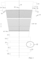
- the corrugated medium 22 is paperboard that includes a plurality of fibers. A majority of the fibers define an elongated shape and are oriented in a generally parallel fashion. The direction in which the majority of the fibers are oriented defines the machine direction "D" of the corrugated medium 22.
- machine direction is defined by the direction in which fibers pass through the paper machine.
- non-machine-direction is defined as the direction transverse to the “machine direction” (i.e., transverse to the fibers of the paperboard).
- the flutes produced by the apparatus 20 are formed generally parallel to the machine direction "D".
- a face sheet (not shown) or the like applied to the flutes can be paperboard and be similarly applied a direction that is substantially parallel to the machine direction "D" of the corrugated medium 22.
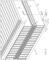
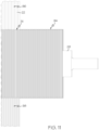
- the formed flute geometry is not illustrated in FIG. 1 .
- the apparatus 20 generally includes a guide roll 24 for guiding the web of medium material (i.e., paperboard), a segmented forming device including plurality of flute forming bars 26 that define a first corrugating labyrinth 29 (see FIG. 5 ), and a pair of corrugating rollers 28, 30 that define a second corrugating labyrinth 31.
- a guide roll 24 for guiding the web of medium material (i.e., paperboard)
- a segmented forming device including plurality of flute forming bars 26 that define a first corrugating labyrinth 29 (see FIG. 5 )
- a pair of corrugating rollers 28, 30 that define a second corrugating labyrinth 31.
- One example web travel pathway for the medium material 22 follows a path around a portion of an outer circumferential surface of the guide roll 24, through the first corrugating labyrinth 29 of the flute forming bars 26, and through the second corrugating labyrinth of the pair of corrugating
- the guide roll 24 can be preceded by various elements, such as one or more idler rollers 32 or the like adapted to carry the web 22 onto the guide roller 24.
- the idler roller 32 can be an fluid flotation idler roller 32 that can use a cushion of fluid, such as air or steam, to reduce, such as eliminate, friction between the web 22 and the idler roller 32.
- the guide roll 24 can be adapted to carry the web 22 into the flute forming bars 26 to longitudinally corrugate the web 22.
- a portion of the guide roll 24 can be adapted to be arranged at an angle relative to another portion of the guide roll 24 such that a path length of an edge portion 34 of the web 22 is shortened relative to a path length of a center portion 36 of the web after leaving the guide roll 24.
- a longitudinally-directed tension is applied to the web 22 to draw the web 22 through the apparatus 20, such as by operation of one or more of the rollers 24, 28, 30, 32, etc. It can be desirable to apply the tension generally constantly across the width of the web 22 to avoid damage to the web 22.
- stressing the web 22 differently (i.e., non-uniformly) in the non-machine direction can cause damage to the paper fibers, wrinkling, buckling, and/or can otherwise stress the paper fibers and reduce the strength thereof.
- an overall width of the web 22 will gradually decrease from an initial non-corrugated width.
- a width of the web 22 will gradually decrease as it passes through the longitudinal forming bars 26 from an entrance end 38 to an exit end 40 thereof.
- the tension across the web 22 should be generally constant.
- an outer portion of the guide roll 24 can be adapted to be arranged at an angle relative to a central portion of the guide roll 24 such that the path length of an edge portion 34 of the web 22 is shortened relative to a path length of a center portion 36 of the web after leaving the guide roll 24.
- the angle of the outer portion of the guide roll 24, relative to the central portion can be chosen such that the path length of the web of the edge portion 34 is substantially equal to the path length of the center portion 36 of the web after leaving the guide roll 24.
- the web 22 can have a first width upon encountering the guide roll 24 that is thereby reduced to a second width after leaving the guide roll 24.
- the guide roll 24 can include at least one element, such as a bowed or curved roll (i.e., a banana roll or the like, not shown) such that one portion of the guide roll 24 is arranged at an angle relative to another portion of the guide roll.
- the single guide roll 24 can be a fixed unitary body in unclaimed embodiments.
- the guide roll 24 includes one portion adjustably movable relative to another portion.
- the guide roll 24A can include at least a first segment 42A defining a first longitudinal axis 44A coupled to an end of a second segment 46A defining a second longitudinal axis 48A.
- the first axis 44A is substantially coaxial with the second axis 48A.
- the first and second segments 42A, 46A can be pivotally coupled to each other at their respective ends such that the guide roll 24A can be pivoted at the center.
- at least one of the first and second segments 42B, 46B can be movable relative to the other of the first and second segments 42B, 46B such that the first axis 44B is oriented at an angle relative to the second axis 48B.
- Each of the first and second segments 42B, 46B can be movable relative to each other, with the first axis 44B being pivotable to a first angle relative to the centerline of the web and the second axis 48B being pivotable to a second angle substantially equal and opposite the first angle.
- each segment 42B, 46B can be geared together so that the pivot angle of the drive side of the bar segment is duplicated by the operator side. For example, if the drive side of the guide roll is pivoted 0.5 degrees toward the flute forming bars 26 (i.e., towards the downstream end), the operator side is also pivoted 0.5 degrees toward the flute forming bars 26. Similarly, if the drive side of the guide roll is pivoted 0.5 degrees away from the flute forming bars 26, the operator side is also pivoted 0.5 degrees away from the fixed flute forming bars 26.
- the multi-segment guide roll 24 can take the edge 34 of the web and direct it at a slight angle to thereby change the length of the edge 34 of the web.
- the web edge 34 will be properly positioned and tensioned without excessively straining the web 22.
- the bar angle can be 0.9 degrees relative to the web 22, though other values can also be used.
- the paperboard web departs toward the flute forming bars 26 at an angle of approximately 1.8 degrees (i.e., 2 x 0.9 degrees).
- the edges 34 of the paperboard web 22 are relatively closer to the corrugating rollers 28, 30 than the center 36 as the paperboard web 22 leaves the guide roll 24 to provide proper edge tension for flute formation.
- the guide roll 24 can be a zero-contact roll being operable to support the web of medium material at a variable height above its outer circumferential surface on a cushion of fluid (i.e., air or steam) that is emitted through openings 47 provided over and through the outer circumferential surface of the guide roll 24.
- a cushion of fluid i.e., air or steam
- openings 47 can be arranged variously, and are illustrated schematically.
- Either or both of the segments 42A, 46A can include the openings for the fluid.
- the air cushion reduces, such as eliminates, sliding friction.
- the multi-segment guide roll 24 can act as a web storage device to make up for web path length changes caused by manufacturing tolerances or the like.
- the zero-contact roll described can be a stationary roll that does not rotate as the web of medium material traverses its circumferential surface. Instead, a volumetric flowrate of air at a controlled pressure is pumped from within the roll 24 radially outward through small openings or holes provided periodically and uniformly over and through the outer circumferential wall of the roll. The result is that the passing web of medium material 22 is supported above the circumferential surface of the zero-contact roll 24 by a cushion of air.
- the nominal height above the circumferential surface of the roll 24 for the traveling web 22 is proportional to the volumetric flowrate of the air that is flowing through the openings in the circumferential surface.
- the air volumetric flowrate is selected to achieve a nominal height for the web 22 (also corresponding to the height of the air cushion) of, e.g., 0.0051-0.0127 meters (0.2-0.5 inch) above the circumferential surface of the roll 24 depending on its radius, which is typically 0.10-0.15 meters (4-6 inches).
- the flowrate can be selected to achieve a lower nominal height, for example 0.0006-0.0025 meters (0.025-0.1 inches) off the circumferential surface of the roll 24.
- the zero-contact roll 24 can also provide an elegant mechanism for providing feedback control for the mean web tension.
- an active or passive pressure transducer (not shown) can be used to detect the pressure in the air cushion that is supporting the web 22 over the surface of the zero-contact roll 24.
- monitoring the air cushion pressure, P provides a real-time measure of the tension in the web 22. For example, if the radius of the roll 24 is fixed at 0.15 meters (6 inches), and the air cushion pressure is measured at 4550.5 Pa (0.66 psi), then one knows the tension in the web at that moment is 700.5 newtons per meter (4 pli).
- the real-time web tension data that can be inferred from measuring the pressure of the air cushion can be used in a feedback control loop to regulate the operation of the apparatus 20.
- zero-contact roll refers to a roll having the above structure, adapted to support a web of material passing over the roll on a cushion of fluid, such as air, that is emitted through holes or openings provided over and through the outer circumferential surface of the roll. It is not meant to imply there can never be any contact (i.e. literally “zero” contact) between the zero-contact roll and the web. Such contact may occur, for example, due to transient or momentary fluctuations in mean web tension.
- the plurality of flute forming bars 26 define a segmented forming device.
- the plurality of flute forming bars 26 are oriented generally along a longitudinal axis of the web 22 to define a first corrugating labyrinth 29 effective to longitudinally corrugate, to an intermediate geometry, the web of medium material that is drawn therethrough. That is, while the plurality of flute forming bars 26 do corrugate the web medium, another downstream structure can finalize the corrugation geometry, such as the corrugating rolls 28, 30. Still, it is possible to utilize the flute forming bars 26 to produce the finalized corrugation geometry.
- the segmented forming device includes two sets of relatively small forming bars that can be pivotally mounted in a frame.
- the plurality of flute forming bars 26 include an upper set 50 of flute forming bars disposed above the web of medium material 22, and a lower set 52 of flute forming bars disposed below the web of medium material 22.
- the upper and lower sets 50, 52 of flute forming bars are interdigitated so as to define the first corrugating labyrinth 29.
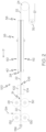
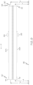
- the example forming bar 54 can include a main bar 56 supporting a corrugation bar 58 thereupon.
- the corrugation bar 58 can be coupled to the main bar 56 in various manners, including fasteners, adhesives, welding, and/or can even be formed therewith. Some or all of the corrugation bars 58 can extend partially or even completely along the longitudinal length of each forming bar 54.
- the main bar 56 and/or the corrugation bar 58 can have a generally hollow interior 60, 62, respectively, though either or both can also be generally solid.
- the plurality of flute forming bars 26 can be extruded or gun drilled to provide the internal hollowed areas 60, 62 that can serve as a distribution manifold for the fluid injected through holes 70 acting as a lubricant in order reduce the frictional forces.
- the main bar 56 can include an end cap 64 or the like (see Fig. 5 ), and/or the corrugation bar 58 can include similar structure.
- the hollow interiors 60, 62 can be in fluid communication, such as through an internal portal 66 to permit a pressurized fluid, such as air or steam, to be delivered therebetween as will be discussed more fully.
- the corrugation bar 58 is the portion that forms the longitudinal flutes in the web 22 passing through the first corrugating labyrinth 29.
- an upper portion of the corrugation bar 58 can include a generally rounded surface portion 68 for contact with the web 22.
- the upper and lower sets 50, 52 of flute forming bars are interdigitated so as to define the first corrugating labyrinth 29. That is, the generally rounded surface portion 68 of adjacent ones of the corrugation bars 58 of the upper and lower sets 50, 52 can be interlocked or intermeshed to define the first corrugating labyrinth 29, extending along the transverse length of the plurality of flute forming bars 26. In effect, the paperboard web 22 passing through the first labyrinth will alternatively pass over and under adjacent ones of the corrugation bars 58 to form the flutes.
- a portion of the plurality of flute forming bars 26, such as all of the bars, include a surface adapted to contact the web of medium material, such as the generally rounded surface portion 68.
- the surface can include an anti-friction surface feature to thereby reduce the frictional forces on the web 22 as it is passing through the first corrugating labyrinth 29.
- a portion of the flute forming bars 26 can be zero-contact bars being operable to support said web of medium material 22 at a variable height thereabove on a cushion of air that is emitted through openings 70 provided over and through an outer surface 68 of the portion of the flute forming bars 26.
- Each surface portion 68 can include a plurality of openings 70 arranged variously thereon that can extend partially or completely along the length of a respective corrugation bar 58.
- Various numbers of openings 70 can be arranged variously, and only a portion are illustrated schematically.
- Pressurized fluid such as air
- a connector 72 or other delivery structure sealingly coupled to a portion of each individual forming bar 54.
- the connector 72 can be coupled to the main bar 56, though it can also be coupled to the corrugation bar 58.
- the connector 72 is coupled to the main bar 56 and the fluid is transferred to the surface 68 of the corrugation bar 58 via the portal 66.
- the connectors 72 of the various bars 58 can be directly (e.g., through a hose or the like) or indirectly (e.g., through a manifold or the like) to a fluid supply 74, in a serial or parallel configuration.
- the pressurized air then exits the corrugation bar 58 through the series of holes 70 spaced along the length of the rod 54 to provide the cushion of air for the paperboard web 22 to float on.
- the cushion of air provides air greasing (i.e., lubrication) that can reduce, such as eliminate, sliding frictional contact between the web 22 and the flute forming surface 68.
- a volumetric flowrate of air at a controlled pressure is pumped from within each forming bar 54 radially outward through the small openings 70 or holes provided periodically and uniformly over and through the outer circumferential surface 68 of the corrugation bar 58.
- the result is that the passing web of medium material 22 is supported above the surface 68 by a cushion of air.
- zero-contact is not meant to imply there can never be any contact (i.e. literally “zero” contact) between the zero-contact bars 58 and the web, such as may occur, for example, due to transient or momentary fluctuations in mean web tension.
- the anti-friction surface feature of the surface portion 68 can include various other structure.
- surface portion 68 can be polished or electro polished in order reduce the frictional forces on the paper as it is passing through the first corrugating labyrinth 29.
- the surface portion 68 can be coated with a release or antifriction coating such as Teflon or similar in order reduce the frictional forces.
- the surface portion 68 can be treated to create a hard surface coating such as provided by black oxide conversion coating, anodizing, flame spraying, deposition coatings, ceramic coating, chrome plating, or other similar surface treatments in order reduce the frictional forces.
- the upper and lower sets of bars 50, 52 are brought gradually closer to each other symmetrically about the web centerline 25 so that each corrugation bar 58 causes the web to begin to form a large sinusoidal shape as the web floats frictionlessly over the bar surface 68.
- the forming bars 54 are angled relative to each other with the entrance end 38 of the bars 56 being relatively farther apart from each other than the exit end 40 of the bars 56. As a result, the complete sinusoidal shape of the flutes can develop gradually as the web travels down the length of the forming bars 54 so that abrupt tension changes in the web are reduced or eliminated as it is condensed inward.
- the plurality of flute forming bars 26 can be adjusted so that any portion of the paper web 22 passing through the first corrugating labyrinth 29 is only curved over or around the radius of the generally rounded surface portion 68 of the corrugation bar 58, or at a maximum the next adjacent bar 58 to it, that the paper web starts on in order to reduce, such as minimize, the stress on the paper fibers.
- the paper web 22 is generally only bent once per flute as it travels through the first corrugating labyrinth 29, and such a partial bend should reduce damage, such as breakage, of the paper fibers.
- Each set of forming bars is mounted in an adjustable framework that allows the individual bars to pivot in an accordion or fan-fold pattern so that the paperboard web is maintained generally parallel to the forming bars. Moreover, the adjustability of the segmented forming device permits various take-up ratios to be used for different flute sizes.
- each of the forming bars 54 can be individually, pivotally fixed, such as at the exit end.
- each forming bar 54 can pivot independently of the other forming bars 54.
- each of the flute forming bars 54 are pivotally coupled, at an exit end 40 thereof, to a support frame 76, 78 such that the flute forming bars are movable laterally (i.e., non-machine-direction), at an entrance end 38 thereof, to individually adjust an angle of each of the flute forming bars 54 relative to the centerline 25 of the web to thereby form a fan of adjustable width.
- Each of the upper and lower sets 50, 52 can have separate support frames 76, 78 or can utilize a single support frame.
- each of the forming bars 54 can be individually coupled to one of the support frames 76, 78 in various manners.
- each forming bar 54 can include a pin 80, clevis, or other pivoting structure coupled to the main bar 56 and in pivotal engagement with a support frame 76, 78.
- the opposite configuration can be utilized to pivotally couple the bars 54 about the entrance end and adjust the angle of the bars about the exit end thereof.
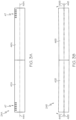
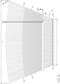
- FIGS. 7-8 illustrate two extreme examples of the adjustable width of the fan-like structure of the flute forming bars 54.
- the entrance end 38 of the plurality of flute forming bars 26 has a first width L 1 that is arranged in the substantially narrowest position. That is, the first width L 1 illustrates the narrowest width of the entrance end 38 in the instant example.
- the exit end 40 of the plurality of flute forming bars 26 has a second width L 2 .
- the second width L 2 illustrates the substantially final width of the web 22 upon exit from the first corrugating labyrinth 29.
- FIG. 7 the entrance end 38 of the plurality of flute forming bars 26 is now illustrated with a third width L 3 that is arranged in the substantially widest position.
- the third width L 3 illustrates the widest width of the entrance end 38 in the instant example.
- the second width L 2 will remain substantially equal between the two extreme examples illustrated in FIGS. 7-8 .
- the web 22 can have various beginning widths, and the width of the entrance end 38 can be adjusted accordingly, the final width of the web 22 upon exit from the first corrugating labyrinth 29 can always be substantially equal to the second width L 2 .
- the two extreme examples illustrated in FIGS. 7-8 are illustrated as extreme examples, and the width of the entrance end 38 can be infinitely adjusted to any desired width therebetween. Still, though described as having one fixed width and one adjustable width end, it is to be understood that the width of each end 38, 40 of the segmented forming device can be configured to be separately and individually adjusted.
- the forming bars 54 can include various structures for varying the width of the adjustable fan to a desired width between the two extreme examples illustrated in FIGS. 7-8 .
- some or all of the forming bars 54 each include a guide track 82 that are coupled to cam rollers 84 of an adjusting framework for permitting the angular adjustment of the forming bars 54 to provide the fan-like or accordion effect as the cam rollers 84 travel back and forth along the guide tracks 82.
- the guide tracks 82 can be disposed generally midway along the length of the forming bars 54, though can also be disposed elsewhere or can even extend along substantially the entire length of the bars 54.
- Some or all of the cam rollers 84 can be coupled to an associated guide track 82 by a linear slide or the like.
- the cam rollers 84 can include rotatable structure to reduce, such as minimize, frictional contact with the guide tracks 82.
- the cams 84 can include static, non-rotational structure that may or may not include frictionreducing surface features, such as any described herein.
- the guide tracks 82 and cam rollers 84 can be a part of the adjusting framework.
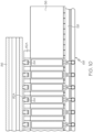
- a single adjusting framework can be utilized to adjust both of the upper and lower sets 50, 52 of forming bars 54, or as shown in FIGS. 9-10 , dual adjusting frameworks can be used to separately adjust the upper and lower sets 50, 52.
- a plurality of upper guide tracks 82A can be each coupled to a respective one of the upper set 50 of flute forming bars 54.
- An upper framework 86 can extend laterally across at least a portion of the upper set 50 of flute forming bars 54 and can include a plurality of cams 84, such as stationary cams or even roller cams or the like, coupled thereto that are each arranged to be received within at least one upper guide track 82A.
- the cams 84 can be arranged variously, such as in an array or the like extending across the upper framework 86 that corresponds generally to the spacing of the plurality of upper guide tracks 82A.
- each roller cam 84 can be adapted to slide along the length of an associated upper guide track 82A.
- only operation of the upper framework 86 is discussed herein with the understanding that the lower framework 88 can similarly operate.
- the upper framework 86 can be movable along the longitudinal axis of the web 22, relative to the upper set of flute forming bars 54, between at least a first position located relatively closer to the entrance end 38 (i.e., corresponding to the first width L 1 of FIG. 7 ) and a second position located relatively closer to the exit end 40 (i.e., corresponding to the first width L 3 of FIG. 8 ). It is to be understood that the two extreme examples illustrated in FIGS. 7-8 are illustrated as extreme examples, and that the upper framework 86 can be longitudinally movable therebetween to infinitely adjust the width of the entrance end 38 to any desired width.
- each cam 84 is not displaceable relative to the upper framework 86. That is, each cam 84 maintains a fixed distance relative to an adjacent cam 84.
- each of the forming bars 54 are pivotally coupled at the exit end 40 to the support frame 76.
- movement of the upper framework 86 along the longitudinal axis of the web 22 causes each of the cams 84 to apply a lateral force to each of the forming bars via the upper guide tracks 82A to thereby.
- each individual forming bar 54 is laterally movable (i.e., non-machine-direction) a distance necessary to maintain an associated cam 84 within an associated upper guide track 82A to individually adjust an angle of each of the flute forming bars 54 relative to the centerline 25 of the web to thereby adjust the width of the fan.
- each individual forming bar 54 is forced to pivot at the exit end 40, and move laterally at the entrance end 38, until a distance between adjacent upper guide tracks 82A is substantially equal to the fixed distance between adjacent cams 84.
- movement of the upper framework 86 towards the first position causes the upper set 50 of flute forming bars 54 to pivot generally towards the centerline 25 of the web 22 to thereby reduce the width of the fan (i.e., towards first width L 1 ).
- movement of the upper framework 86 towards the second position causes the upper set 50 of flute forming bars 54 to pivot generally away from the centerline 25 of the web 22 to thereby increase the width of the fan (i.e., towards third width L 3 ).
- a plurality of lower guide tracks 82B can be each coupled to a respective one of the lower set 52 of flute forming bars 54.
- the lower framework 88 can include similar structure. That is, the lower framework 88 can extend laterally across at least a portion of the upper set 50 of flute forming bars 54, and can include a plurality of cams (not shown), such as stationary cams or even roller cams or the like, coupled thereto that are each arranged to be received within at least one lower track 82B.
- the upper framework 86 can be movable along the longitudinal axis of the web 22, relative to the upper set of flute forming bars 54, between at least a first position located relatively closer to the entrance end 38 (i.e., corresponding to the first width L 1 of FIG. 7 ) and a second position located relatively closer to the exit end 40 (i.e., corresponding to the first width L 3 of FIG. 8 ), though is also longitudinally movable therebetween to infinitely adjust the width of the entrance end 38 to any desired width.
- each of the upper and lower frameworks 86, 88 can separately and independently adjust the width of the upper and lower sets 50, 52 of forming bars 54.
- the lower framework 88 can be operatively coupled to the upper framework 86, such as by various direct or indirect links 90 (shown schematically in FIG. 4 ) so as to be movable together therewith between the first and second positions of FIGS. 7-8 .
- various direct or indirect links 90 shown schematically in FIG. 4
- movement of the upper framework 86 towards the second position can cause, via the link 90, both of the upper and lower sets 50, 52 of flute forming bars 54 to pivot generally away from the centerline 25 of the web 22 to thereby increase the width of the fan, or vice versa.
- the lower framework 88 can be operatively coupled to the upper framework 86 directly or indirectly through a control system, such as via various motors, drive mechanisms, gearing, etc.
- a vertical distance or gap between the upper set 50 of forming bars 54 and the lower set 52 of forming bars can generally taper or decrease from the entrance end 38 to the exit end 40 to progressively form the corrugated geometry of the web 22. That is, a vertical distance between the upper and lower sets 50, 52 can be relatively greater about the entrance end 38, and relatively less about the exit end 40. As shown in FIG. 9 , the vertical distances can be measured relative to a fixed reference point, such as a support surface 92 or the like.
- the difference (L 6 - L 4 ) between the vertical distance L 6 of the upper set 50 and L 4 of the lower set 52, at the entrance end 38, can be relatively greater than the difference (L 5 - L 4 ) between the vertical distance L 5 of the upper set 50 and L 4 of the lower set 52, at the exit end 40.
- the lower set 52 can remain generally fixed vertically, such that the vertical distance L 4 can be generally equal between the support surface 92 and either end 38, 40.
- the tapering between the upper and lower sets 50, 52 can be accomplished by pivoting the upper set 50 relative to the lower set 52.
- Either or both ends 38, 40 of the upper set 50 can be pivotally adjustable relative to the lower set 52.
- the exit end 40 remains generally vertically fixed, while the entrance end 38 is vertically adjustable via pivoting of the upper set 50 generally about the exit end 40. Still, it is to be understood that either or both of the upper and lower sets 50, 52 can remain fixed or be vertically adjustable at either end.
- the tapering distance of the upper and lower sets 50, 52 permits the flute geometry to be formed from a relatively high amplitude, low frequency shape near the entrance end 38 to a relatively low amplitude, high frequency shape near the exit end 40, corresponding to the desired flute size.
- the forming bars 54 are oriented at a relatively slight angle with respect to the web, there can be little or no tension force to be overcome by the anti-friction surface feature of the outer surface 68 of the forming bars 54.
- the web 22 is in a generally sinusoidal shape and can be substantially fully condensed in width (i.e., approximately 1.27 meters (50 inches) in the instant example). Still, various downstream corrugating elements may still further condense the width of the web 22.
- the plurality of flute forming bars 26 are adapted to be dynamically adjustable while the web of medium material is actively moving through the first corrugating labyrinth 29 so that a portion of the web 22 passing therethrough is maintained at a substantially constant web tension in a cross-machine direction.
- the width of the adjustable fan can be dynamically adjusted via the upper and lower frameworks 86, 88.
- the vertical distance or gap between the upper and lower sets 50, 52 can be dynamically adjusted between the entrance end 38 to the exit end 40.
- an automatic control system can be provided with motors, drive mechanisms, gearing, sensors, and positional feedback on some or all of the movable adjustments. In response to signals from these sensor(s), the automatic control system can utilize an open or closed feedback control loop as known in the art to regulate the operation of the apparatus 20. It is recognized that an iterative process of trial and error may be desirable to discover optimal adjustment values.
- a feedforward control loop could even be used so the control system can anticipate changes in incoming medium material and make appropriate corrections.
- the control system can be interconnected with a pressure transducer of one of the guide roll 24 or forming bars 54 or elsewhere to dynamically determine web tension. Such a fully automatic control system can reduce, such as minimize changeover time between products having different web widths and/or desired corrugated geometry.
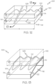
- a pair of corrugating rollers 28, 30 define a second corrugating labyrinth 31. More specifically, the pair of corrugating rollers 28, 30 cooperate to define, at a nip therebetween, the second corrugating labyrinth 31 between respective and interlocking pluralities of corrugating teeth 94 provided on the corrugating rollers 28, 30.
- the pluralities of corrugating teeth 94 are arranged cylindrically along the longitudinal length of each of the rollers 28, 30 so as to longitudinally corrugate the web 22 passing through the second labyrinth 31.
- the interlocking pluralities of corrugating teeth 94 receive an intermediate flute geometry 96 (i.e., such as the output of the first or third corrugating labyrinths), and are effective to longitudinally corrugate, to a substantially final flute geometry 98, the web 22 of medium material that is drawn through the nip on rotation of the corrugating rollers 28, 30. That is, as shown, the second corrugating labyrinth 31 can be the final structure for longitudinally corrugating the web 22 to a final, desired flute geometry.
- an intermediate flute geometry 96 i.e., such as the output of the first or third corrugating labyrinths
- the corrugating rollers 28, 30 are mounted adjacently and cooperate with each other, such that the web 22 passes through the nip and is compressed therebetween. Both the rollers 28, 30 are journaled for rotation on respective substantially parallel axes, and together they define a substantially serpentine or sinusoidal pathway or corrugating labyrinth 31 at the nip between them. For example, as with the first corrugating labyrinth 29, the teeth 94 of the rollers 28, 30 can be interdigitated to define the second corrugating labyrinth 31.
- the second corrugating labyrinth 31 is produced by a first set of cylindrically arranged corrugating teeth 94 disposed along the longitudinal length of one roller 28 that are received within the valleys defined between a second set of cylindrically arranged corrugating teeth (not shown) disposed along the longitudinal length of the other roller 30, and vice versa.
- Both sets of teeth 94 are provided so that individual teeth span the full length of the respective rolls 28, 30, or at least the width of the web 22 that traverses the second corrugating labyrinth 31 therebetween, so that full-width corrugations can be produced in that web 22 as the teeth 94 interlock with one another at the nip as the rolls rotate.
- the corrugating rollers 28, 30 are rotated in opposite angular directions such that the web of medium material 22 is drawn through the nip, and is forced to negotiate the second corrugating labyrinth 31 defined between the opposing and interlocking sets of corrugating teeth 94.
- the medium material 22 On exiting the nip (and corrugating labyrinth 31), as will be understood by those of ordinary skill in the art the medium material 22 has a corrugated form in a substantially final geometry; i.e. a substantially serpentine longitudinal cross-section having opposing flute peaks and valleys on opposite sides or faces of the medium material 22.
- precise downstream tension control also can be selected by adjusting the radial velocity (and correspondingly the surface linear velocity) of the corrugating rollers 28, 30.
- the apparatus 20 can further include additional structure.
- a fixed forming device 100 can be disposed between the plurality of flute forming bars 26 and the pair of corrugating rollers 28, 30.
- the fixed forming device 100 can define a third corrugating labyrinth 106 effective to longitudinally corrugate, to a near-final geometry, the web 22 of medium material that is drawn therethrough.
- the elements of the fixed forming device 100 have a width W and remain generally fixed, such that the width W is generally not adjustable. Thus, there may be little, such as zero, transverse movement of the web 22 passing through the fixed forming device 100.
- the final width of the web 22 can remain generally constant before and after the fixed forming device 100, while the height of the flutes is further reduced towards a final flute geometry.
- a vertical height between the elements can be adjustable, or may also be non-adjustable. Because the elements of the fixed forming device 100 can be non-adjustable, different sets of elements may be removed and replaced for each desired web width and/or final desired corrugated flute geometry. In other cases, the fixed forming device 100 may not be used, such as where a desired web with exceeds the maximum width W of the device 100.
- the web travel pathway for the medium material follows a path around a portion of an outer circumferential surface of the guide roll, through the first corrugating labyrinth, through the third corrugating labyrinth, and finally through the second corrugating labyrinth.
- the fixed forming device 100 can have a fixed flute forming geometry. To accommodate various flute sizes, the fixed forming device 100 can be suitably replaced, along with the downstream corrugating rolls 28, 30.
- the fixed flute forming device 100 can include two machined shapes that have the large sinusoidal pattern at the entry end, and the final flute pattern at the exit end. The two machined shapes are generally similar, and are positioned above and below the paperboard web.
- the fixed forming device 100 can include an upper die 102 disposed above the web 22 of medium material and a lower die 104 disposed below the web 22 of medium material.
- the upper and lower dies 102, 104 can each include fixed flute-forming teeth 108 that are interdigitated so as to define the third corrugating labyrinth 106. That is, a generally rounded surface portion of adjacent teeth 108 of the upper and lower dies 102, 104 can be interlocked or intermeshed to define the third corrugating labyrinth 106, extending along the transverse width W of the fixed forming device 100.
- the paperboard web 22 passing through the third labyrinth 106 will alternatively pass over and under adjacent ones of the teeth 108 to form the flutes to a near-final geometry that can be further refined downstream by the rollers 28, 30.
- the surface of the upper and lower dies 102, 104 can include an anti-friction surface feature to thereby reduce the frictional forces on the web 22 as it is passing through the third corrugating labyrinth 106.
- a portion of the upper and lower dies 102, 104 can include zero-contact structure being operable to support said web of medium material 22 at a variable height thereabove on a cushion of air that is emitted through openings 110 provided over and through an outer surface 112 of the portion of the upper and lower dies 102, 104.
- a plurality of openings 110 can be arranged variously thereon that can extend partially or completely along the width W of a respective upper and lower die 102, 104.
- the upper and lower dies 102, 104 can be zero-contact surfaces being operable to support the web of medium material at a variable height above their surface 112 on a cushion of fluid (i.e., air or steam) that is emitted through the openings 110.
- the air cushion provides air greasing (i.e., lubrication) that can reduce, such as eliminate, sliding frictional contact between the web 22 and the teeth 108.
- the pressurized fluid, such as air can delivered to one or more openings 114 sealingly coupled to a portion of the upper and lower dies 102, 104.
- the openings 114 can be directly or indirectly in fluid communication with the openings 110, such as via an open manifold 116 disposed within an interior of the upper and lower dies 102, 104.
- zero-contact is not meant to imply there can never be any contact (i.e. literally “zero” contact) between the zero-contact surface and the web, such as may occur, for example, due to transient or momentary fluctuations in mean web
- the anti-friction surface feature of the surface 112 of the upper and lower dies 102, 104 can include various other structure.
- surface portion 112 can be polished or electro polished in order reduce the frictional forces on the paper as it is passing through the third corrugating labyrinth 106.
- the surface portion 112 can be coated with a release or antifriction coating such as Teflon or similar in order reduce the frictional forces.
- the surface portion 112 can be treated to create a hard surface coating such as provided by black oxide conversion coating, anodizing, flame spraying, deposition coatings, ceramic coating, chrome plating, or other similar surface treatments in order reduce the frictional forces.
- the two patterns of the fixed flute forming device 100 can be blended together (e.g., lofted) so that as the paperboard web passes between the upper and lower dies 102, 104 the sinusoidal shape transitions gradually corresponding to the desired flute size. Since the transition is gradual and the forces applied to the web are generally parallel to the tension force of the paperboard web, there is little or no damage to the web. More specifically, a vertical distance or gap between the upper and lower dies 102, 104 can generally taper or decrease from an entrance end 118 to an exit end 120 to progressively form the corrugated geometry of the web 22. That is, a vertical distance between the upper and lower dies 102, 104 can be relatively greater about the entrance end 118, and relatively less about the exit end 120.
- the tapering can be accomplished by a ramped geometry 122 on either or both of the upper and lower dies 102, 104. Still, it is to be understood that either or both of the upper and lower dies 102, 104 can remain fixed or even be vertically adjustable. Thus, the tapering distance of the upper and lower dies 102, 104 permits the flute geometry to be formed from a relatively high amplitude, low frequency shape near the entrance end 118 to a relatively low amplitude, high frequency shape near the exit end 120, corresponding to the desired flute size.
- the downstream corrugating rolls 28, 30 can each have a fluted geometry similar to that of the fixed forming device 100 for maintaining, or even further refining, the final flute shape. As a result, this process can significantly reduce the strength reduction undergone by the paperboard web in comparison to a conventional process, which can see tension spikes as high as 400% of running tension.
- a final corrugating roll 130 can have a similar fluted geometry as the corrugating rollers 28, 30, while a single-face roller 132, such as a pressure roll, can be used to apply a face sheet 134 to the corrugated webbing 22 to form a single-faced corrugated board 136.
- a further rollers can apply other face sheets (not shown), such as to form a double-faced corrugated board (not shown).
- the corrugated web 22 alone can be stored or otherwise processed.
- the single-faced corrugated board 136 produced by the apparatus 20 can be stored or otherwise further utilized in the manufacturing process.
- the single-faced corrugated board 136 can be continuously formed into a double/triple/quadruple, etc. wall design to increase strength.
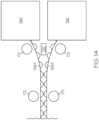
- a first single-faced sheet 136A can be produced by a first apparatus 140 (i.e., similar to the apparatus 20) while a second single-faced sheet 136B can be produced by a second apparatus 142 (i.e., also similar to the apparatus 20).
- first apparatus 140 i.e., similar to the apparatus 20
- a second single-faced sheet 136B can be produced by a second apparatus 142 (i.e., also similar to the apparatus 20).
- each of the first and second apparatuses 140, 142 can each produce similar linearly corrugated board, and may even be vertically arranged as shown.
- FIG. 14 is illustrated schematically, and as such the single-faced sheets 136A, 136B are illustrated in a manner to demonstrate the concepts discussed herein.
- the flutes of the single-faced sheets 136A, 136B would extend longitudinally from the machines 140, 142 (i.e., in the machine direction).
- the first and second single-faced sheets 136A, 136B produced thereby can be coupled together in various manners for form various double wall designs.
- Vertical arrangement of two apparatuses 140, 142 can facilitate forming either of the panels 150, 160 discussed below because such an arrangement can provide increased registration accuracy between the single-faced sheets 136A, 136B.
- single-faced sheets are discussed, it is to be understood that various other styles can be used (i.e., double/triple faced sheets) to form various double/triple/quadruple, etc. wall designs.
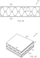
- the first and second single-faced sheets 136A, 136B produced thereby can be coupled together to continuously form a single multi-layer corrugated panel 150, with the two single-faced sheets 136A, 136B being bonded together at the flute tips. That is, the flutes 144 of the first single-faced sheet 136A can be bonded directly to the flutes 146 of the second single-faced sheet 136B, at the flute tips, by various glues / adhesives 148. Thus, a flute-to-flute bond (e.g., an "X" flute) that can eliminate an interior double wall.
- a flute-to-flute bond e.g., an "X" flute
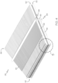
- the first and second single-faced sheets 136A, 136B produced thereby can be coupled together to continuously form a single multi-layer corrugated panel 160, with the two single-faced sheets 136A, 136B being arranged at an angle relative to each other.
- the two single-faced sheets 136A, 136B are arranged generally perpendicular relative to each other (i.e., flutes 144 are generally perpendicular to flutes 146), though various other angles can also be used.
- An interior wall 162 can be disposed between the two single-faced sheets 136A, 136B by various glues / adhesives.
- a cross flute, double wall design 160 can be formed to increase strength. That is, each flute layer can be oriented at an angle relative to adjacent layers to provide strength across multiple force vectors.
- one or more interior elements 170 can apply adhesive to the flute tips to form the flute-to-flute panel 150.
- the interior element 170 can apply the interior layer 162 and/or adhesives to form the cross-flute panel 160.
- various rollers 172 or the like can guide the two single-faced sheets 136A, 136B, and/or can even be utilized as pressure rolls to apply one of the sheets 136A to the other sheet 136B.
- the individual single-faced sheets 136A, 136B need not be formed using the same process or apparatus, and that various types of sheets can be bonded together.
- the corrugation apparatus 20 and process of the instant application can provide some highly beneficial results, including but not limited to the following: (1) The process significantly reduces the strength reduction undergone by the paperboard web in comparison to a conventional process, which can see tension spikes as high as 400% of running tension; (2) Double wall strength can be equal to or greater than current triple wall or triple wall made with vastly reduced basis weight; (3) Triple wall can be equal to or greater than current 4-wall or 4-wall made with vastly reduced basis weight; (4) Laminated 4- or 5-wall board with two cross flute sections would be very strong or could be made with vastly reduced basis weight; (5) Increased burst strength even at lower basis weights due to the liner applicator applying a continuous film to the liners; and (6) The possibility to add moisture resistance to the liners since the adhesive can be applied as a continuous film.
- the corrugated board can be formed with a cold adhesive (e.g., at or near room temperature) such that little or no drying energy can be required.
- the cold adhesive can be applied as a relatively thin film that bonds to the corrugation by pressure pulses as it exits the single facer.
Claims (6)
- Verfahren zur Herstellung einer in Längsrichtung gewellten Bahn, umfassend:zuerst Führen einer Bahn (22) aus Medium-Material um einen Teil einer äußeren Umfangsfläche einer Führungsrolle (24), wobei ein Teil (42) der Führungsrolle (24) relativ zu einem anderen Teil (46) der Führungsrolle (24) einstellbar beweglich ist, so dass eine Weglänge eines Randabschnitts (34) der Bahn (22) relativ zu einer Weglänge eines Mittelabschnitts (36) der Bahn nach dem Verlassen der Führungsrolle (24) verkürzt ist,anschließend Ziehen der Bahn aus Medium-Material (22) durch eine Vielzahl von wellenbildenden Stangen (26), die allgemein entlang einer Längsachse der Bahn ausgerichtet sind, um ein erstes Riffellabyrinth (29) zu definieren, um die Bahn aus Medium-Material (22) in Längsrichtung zu wellen, wobei die Vielzahl von wellenbildenden Stangen (26) einen oberen Satz (50) von wellenbildenden Stangen, der über der Bahn aus Medium-Material (22) angeordnet ist, und einen unteren Satz (52) von wellenbildenden Stangen, der unter der Bahn aus Medium-Material (22) angeordnet ist, umfasst, wobei der obere und der untere Satz (50, 52) von wellenbildenden Stangen verzahnt sind, um das erste Riffellabyrinth (29) zu definieren,dynamisches Einstellen des Vertikalabstands oder Spalts zwischen dem oberen und dem unteren Satz (50, 52) zwischen einem Eingangsende (38) und dem Ausgangsende (40) der Vielzahl von wellenbildenden Stangen (26), während sich die Bahn aus Medium-Material (22) aktiv durch das erste Riffellabyrinth (29) bewegt.
- Verfahren gemäß Anspruch 1, wobei ein in Längsrichtung gerichteter Zug allgemein konstant über die Breite der Bahn (22) angewendet wird, während sich die Bahn (22) in der Maschinenrichtung bewegt.
- Verfahren gemäß einem der vorstehenden Ansprüche, ferner umfassend, nach dem Einführen von Wellen in die Bahn (22), Einführen von längslaufenden Wellungen darin mit einer niedrigeren Amplitude und höheren Frequenz als jene der Wellen durch Drehen des oberen Satzes (50) von wellenbildenden Stangen relativ zu dem unteren Satz (52) von wellenbildenden Stangen, um den Abstand zwischen dem oberen und dem unteren Satz (50, 52) von dem Eingangsende (38) zu dem Ausgangsende (40) zu verringern.
- Verfahren gemäß einem der vorstehenden Ansprüche, wobei ein Teil der wellenbildenden Stangen (26) funktionsfähig ist, die Bahn aus Medium-Material (22) in einer variablen Höhe darüber auf einem Kissen aus Fluid zu tragen, das durch Öffnungen (70) emittiert wird, die über und durch eine Außenoberfläche (68) des Teils der wellenbildenden Stangen (26) bereitgestellt sind.
- Verfahren gemäß einem der vorstehenden Ansprüche, wobei, wenn die Bahn (22) aus dem ersten Riffellabyrinth (29) der wellenbildenden Stangen (26) austritt, die Bahn (22) in einer allgemein sinusförmigen Form vorliegt.
- Verfahren gemäß einem der vorstehenden Ansprüche, ferner umfassend, nach dem Ziehen der Bahn aus Medium-Material (22) durch das erste Riffellabyrinth (29), anschließend Ziehen der Bahn aus Medium-Material (22) durch ein Paar von Riffelwalzen (28, 30), die zusammenwirken, um an einem Spalt dazwischen ein zweites Riffellabyrinth (31) zwischen entsprechenden und verzahnten Vielzahlen von Riffelzähnen (94), die auf den Riffelwalzen (28, 30) bereitgestellt sind, zu definieren, wobei die Vielzahlen von Riffelzähnen (94) zylindrisch entlang jeder der Rollen (28, 30) angeordnet sind, wobei die verzahnten Vielzahlen von Riffelzähnen (94) wirksam sind, die Bahn aus Medium-Material (22), die bei Drehung der Riffelwalzen (28, 30) durch den Spalt gezogen wird, in Längsrichtung zu wellen.
Applications Claiming Priority (3)
| Application Number | Priority Date | Filing Date | Title |
|---|---|---|---|
| US3851308P | 2008-03-21 | 2008-03-21 | |
| PCT/US2009/037959 WO2009117732A2 (en) | 2008-03-21 | 2009-03-23 | Apparatus for producing corrugated board |
| EP09721657.6A EP2265438B1 (de) | 2008-03-21 | 2009-03-23 | Vorrichtung zur herstellung von wellpappe |
Related Parent Applications (2)
| Application Number | Title | Priority Date | Filing Date |
|---|---|---|---|
| EP09721657.6A Division EP2265438B1 (de) | 2008-03-21 | 2009-03-23 | Vorrichtung zur herstellung von wellpappe |
| EP09721657.6A Division-Into EP2265438B1 (de) | 2008-03-21 | 2009-03-23 | Vorrichtung zur herstellung von wellpappe |
Publications (2)
| Publication Number | Publication Date |
|---|---|
| EP3508339A1 EP3508339A1 (de) | 2019-07-10 |
| EP3508339B1 true EP3508339B1 (de) | 2023-11-15 |
Family
ID=41091571
Family Applications (2)
| Application Number | Title | Priority Date | Filing Date |
|---|---|---|---|
| EP19157014.2A Active EP3508339B1 (de) | 2008-03-21 | 2009-03-23 | Verfahren zur herstellung von wellpappe |
| EP09721657.6A Active EP2265438B1 (de) | 2008-03-21 | 2009-03-23 | Vorrichtung zur herstellung von wellpappe |
Family Applications After (1)
| Application Number | Title | Priority Date | Filing Date |
|---|---|---|---|
| EP09721657.6A Active EP2265438B1 (de) | 2008-03-21 | 2009-03-23 | Vorrichtung zur herstellung von wellpappe |
Country Status (6)
| Country | Link |
|---|---|
| US (4) | US8672825B2 (de) |
| EP (2) | EP3508339B1 (de) |
| JP (2) | JP5459684B2 (de) |
| CA (1) | CA2718984C (de) |
| ES (1) | ES2742693T3 (de) |
| WO (1) | WO2009117732A2 (de) |
Families Citing this family (17)
| Publication number | Priority date | Publication date | Assignee | Title |
|---|---|---|---|---|
| ES2742693T3 (es) * | 2008-03-21 | 2020-02-17 | Hbk Family Llc | Aparato para producir cartón corrugado |
| JP5890683B2 (ja) * | 2011-01-28 | 2016-03-22 | キヤノン株式会社 | 情報処理装置およびその方法 |
| US20130015093A1 (en) * | 2011-07-11 | 2013-01-17 | International Paper Company | Corrugated Paperboard Laminate Trays and Displays |
| EP3251826B1 (de) | 2012-11-01 | 2020-07-22 | HBK Family, LLC | Verfahren zum riffeln einer bahn in maschinenrichtung |
| US11420417B2 (en) | 2013-03-15 | 2022-08-23 | Scorrboard Llc | Methods and apparatus for producing scored mediums, and articles and compositions resulting therefrom |
| BR112015023798B1 (pt) | 2013-03-15 | 2021-07-13 | Scorrboard, Llc | Método para criar uma modificação nivelada em um papelão ondulado |
| US9512338B2 (en) | 2014-04-29 | 2016-12-06 | Greif Packaging Llc | Method for manufacturing an adhesive compound for use in the production of corrugated paperboard |
| US20170274616A1 (en) * | 2016-03-22 | 2017-09-28 | Scorrboard, Llc | System and method for inducing fluting in a paper product by embossing with respect to machine direction |
| US20170282489A1 (en) * | 2016-04-01 | 2017-10-05 | Scorrboard, Llc | System and method for producing multi-layered board having a corrugated medium and an embossed medium |
| US10800133B2 (en) | 2016-04-20 | 2020-10-13 | Scorrboard, Llc | System and method for producing a facing for a board product with strategically placed scores |
| US10328654B2 (en) | 2016-04-20 | 2019-06-25 | Scorrboard, Llc | System and method for producing a multi-layered board having a medium with improved structure |
| US11027515B2 (en) | 2016-04-20 | 2021-06-08 | Scorrboard Llc | System and method for producing multi-layered board having at least three mediums with at least two mediums being different |
| US11027513B2 (en) | 2016-04-20 | 2021-06-08 | Scorrboard Llc | System and method for producing an articulating board product having a facing with score lines in register to fluting |
| US10145108B2 (en) * | 2016-05-12 | 2018-12-04 | Aryan Twenty 5, LLC | Panel and method for fabricating, installing and utilizing a panel |
| EP3972825A4 (de) * | 2019-08-05 | 2022-06-08 | Intpro, Llc | Papierspezifische feuchtigkeitsregelung in einer laufenden papierbahn |
| US20220080696A1 (en) * | 2020-09-16 | 2022-03-17 | Packsize Llc | Systems and methods for forming dual fluted corrugated board |
| CN115214114B (zh) * | 2022-07-20 | 2023-12-29 | 江苏至臻环保科技集团有限公司 | 一种纳米滤料皱折加工装置 |
Family Cites Families (160)
| Publication number | Priority date | Publication date | Assignee | Title |
|---|---|---|---|---|
| US1848583A (en) * | 1932-03-08 | swift | ||
| USRE20970E (en) * | 1939-01-03 | Apparatus for imparting stretchability to webs | ||
| US654884A (en) * | 1899-07-20 | 1900-07-31 | Jeffrey T Ferres | Apparatus for making corrugated paper. |
| US739276A (en) | 1902-05-12 | 1903-09-22 | Walter L Allen | Machine for corrugating paper. |
| US1199508A (en) * | 1914-12-24 | 1916-09-26 | George W Swift Jr | Corrugated paper-board and process of making the same. |
| US1627966A (en) * | 1920-04-17 | 1927-05-10 | Arkell Safety Bag Co | Apparatus for operating on paper and other fabrics |
| US1468766A (en) * | 1921-09-09 | 1923-09-25 | Herbert E Van Dorn | Drawbar carrier |
| GB199538A (en) | 1922-04-13 | 1923-06-28 | Frederick Rippon Reynolds | Improvements in and relating to machines for the production of pleated or creased paper, fabrics and the like |
| US1834648A (en) * | 1930-03-03 | 1931-12-01 | Johns Manville | Corrugating machine |
| DE595275C (de) | 1932-11-29 | 1934-04-07 | Jacob Moll | Einrichtung zum Herstellen von laengsgewellten Bahnen aus Papier, Pappe usw. |
| US1981338A (en) * | 1934-01-10 | 1934-11-20 | George W Swift Jr Inc | Machine for making corrugated paper board |
| US2257429A (en) * | 1937-08-04 | 1941-09-30 | Ruegenberg Gottfried | Process for producing all-around extensible paper |
| US2163063A (en) * | 1937-08-11 | 1939-06-20 | Hippolyte W Romanoff | Machine for making corrugated articles |
| US2236932A (en) * | 1938-01-27 | 1941-04-01 | Arentsen Gerrit Jan | Apparatus for continuously manufacturing corrugated construction boards |
| US2398844A (en) * | 1944-03-04 | 1946-04-23 | Combined Locks Paper Co | Paper coating |
| US2494431A (en) | 1945-06-28 | 1950-01-10 | Karl J Eckstein | Continuous corrugating mechanism |
| US2622558A (en) * | 1948-01-19 | 1952-12-23 | Inland Wallpaper Company | Machine for coating web material |
| US2793676A (en) * | 1952-04-14 | 1957-05-28 | Theodor Bell & Cie Ag | Apparatus for corrugating paper or cardboard |
| US3002876A (en) * | 1955-10-22 | 1961-10-03 | Rosati Gildo | Apparatus for corrugating paper in a direction parallel to the length of the sheet |
| US3024496A (en) * | 1957-04-05 | 1962-03-13 | S Lavorazione Materie Plastisc | Method and apparatus for manufacturing corrugated thermoplastic sheets |
| US3046935A (en) * | 1957-05-24 | 1962-07-31 | S & S Corrugated Paper Mach | Gluing control means |
| NL275557A (de) * | 1957-12-23 | |||
| US2960145A (en) * | 1958-07-14 | 1960-11-15 | Ruegenberg Gottfried | Method of and apparatus for manufacturing longitudinally folded or longitudinally arched, particularly longitudinally corrugated webs of paper, carton, cardboard, plastics or the like |
| US3077222A (en) * | 1959-09-23 | 1963-02-12 | Diamond Alkali Co | Apparatus for producing corrugated board |
| NL280801A (de) * | 1961-07-17 | |||
| US3300359A (en) * | 1962-02-06 | 1967-01-24 | Willem A Nikkel | Method and apparatus for making corrugated board |
| US3178494A (en) * | 1962-11-15 | 1965-04-13 | Lucien E Tisdale | Method and apparatus for forming longitudinal corrugations in sheet material |
| US3306805A (en) * | 1963-05-20 | 1967-02-28 | Novelart Mfg Company | Apparatus for making printed corrugated paper board |
| JPS4023188Y1 (de) | 1964-01-17 | 1965-08-07 | ||
| US3303814A (en) * | 1964-07-28 | 1967-02-14 | Koppers Co Inc | Apparatus for applying adhesive to a moving web |
| US3479240A (en) | 1964-08-03 | 1969-11-18 | Harris Intertype Corp | Prefeeder mechanism for single facer machines |
| US3383234A (en) | 1964-08-31 | 1968-05-14 | Samuel M Langston Co | Applicator roll with metering means |
| US3425888A (en) | 1964-09-04 | 1969-02-04 | Keith Q Kellicutt | Method and apparatus for producing faced corrugated materials |
| GB1181161A (en) * | 1967-05-22 | 1970-02-11 | Morane Plastic Company Ltd | Laminating Machine |
| US3676247A (en) * | 1969-02-03 | 1972-07-11 | Australian Paper Manufacturers | Corrugating paperboard |
| JPS4821676B1 (de) | 1969-03-12 | 1973-06-30 | ||
| US3676263A (en) * | 1970-03-26 | 1972-07-11 | Ridge Ply Inc | Machine for making stress laminated panel |
| US3738905A (en) | 1970-04-29 | 1973-06-12 | Kimberly Clark Co | Paper toweling material and method of combining into multi ply products |
| JPS4821676Y1 (de) | 1970-05-20 | 1973-06-23 | ||
| US3648913A (en) * | 1970-09-10 | 1972-03-14 | Harris Intertype Corp | Noiseless paperboard guide |
| US3700518A (en) | 1971-03-17 | 1972-10-24 | Honshu Paper Co Ltd | Method for manufacturing a composite corrugated paper board |
| US3773587A (en) | 1971-07-01 | 1973-11-20 | Domtar Ltd | Manufacture of corrugated board |
| US3892613A (en) | 1971-07-22 | 1975-07-01 | Int Paper Co | Method of making corrugated paperboard |
| JPS5221433B2 (de) | 1971-08-17 | 1977-06-10 | ||
| US3788515A (en) * | 1972-03-20 | 1974-01-29 | Koppers Co Inc | Method and apparatus for guiding and tensioning a web |
| GB1481050A (en) * | 1973-10-30 | 1977-07-27 | Mitsubishi Petrochemical Co | Corrugated cardboard sheet and method for producing the same |
| US3966518A (en) | 1973-12-26 | 1976-06-29 | Molins Machine Company, Inc. | Paperboard corrugator |
| US3981758A (en) * | 1974-11-04 | 1976-09-21 | Koppers Company, Inc. | Process control system for corrugators |
| US3993425A (en) | 1975-03-20 | 1976-11-23 | The Real-Reel Corporation | Apparatus for forming diagonally corrugated paperboard |
| BE942704A (fr) | 1975-06-10 | 1976-10-01 | Cellcor Corp Of Canada Ltd | Procédé et appareil pour modifier l'amidon. |
| GB1544634A (en) | 1975-07-04 | 1979-04-25 | Simon Container Mach Ltd | Corrugating machinery |
| US4177102A (en) * | 1976-04-19 | 1979-12-04 | Rengo Co., Ltd. | Single facer for manufacturing single-faced corrugated board |
| JPS52148396A (en) * | 1976-06-04 | 1977-12-09 | Kobayashi Seisakusho | Apparatus for forming corrugation of corrugated cardboard in direction of flow of sheet |
| JPS52156090A (en) * | 1976-06-18 | 1977-12-26 | Kobayashi Seisakusho | Apparatus for forming corrugation of corrugated cardboard in direction of flow of sheet |
| CA1072873A (en) | 1976-06-28 | 1980-03-04 | Weyerhaeuser Company | Corrugating process |
| JPS5310833U (de) | 1976-07-13 | 1978-01-30 | ||
| US4126508A (en) | 1976-09-13 | 1978-11-21 | Boise Cascade Corporation | Apparatus for forming multi-flute-layer corrugated board |
| US4104107A (en) * | 1977-03-18 | 1978-08-01 | Koppers Company, Inc. | Apparatus for urging web guides toward the corrugating roll of a single facer |
| US4134781A (en) * | 1977-05-03 | 1979-01-16 | Key Chemicals, Inc. | Method for controlling warp in the manufacture of corrugated paperboard |
| US4170347A (en) * | 1977-06-22 | 1979-10-09 | E. I. Du Pont De Nemours And Company | Web pleater |
| US4334154A (en) * | 1977-12-02 | 1982-06-08 | General Electric Company | Tomographic scanning apparatus |
| JPS54116180U (de) * | 1978-01-31 | 1979-08-15 | ||
| US4179253A (en) | 1978-04-10 | 1979-12-18 | Domtar Inc. | Linear corrugating roll deflection control |
| DE2851007C3 (de) * | 1978-11-24 | 1982-02-04 | BHS-Bayerische Berg-, Hütten- und Salzwerke AG, 8000 München | Vorrichtung zur Herstellung einer wenigstens einseitig deckbelegten Wellpappe |
| GB2039559A (en) * | 1979-01-18 | 1980-08-13 | Munters Corp | Apparatus for producing a corrugated sheet |
| US4316755A (en) * | 1979-03-20 | 1982-02-23 | S&S Corrugated Paper Machinery Co., Inc. | Adhesive metering device for corrugating processes |
| US4351264A (en) * | 1979-03-20 | 1982-09-28 | S&S Corrugated Paper Machinery Co., Inc. | Adhesive metering device |
| US4338154A (en) | 1979-09-14 | 1982-07-06 | S. A. Martin | Machine for producing single-face corrugated board |
| US4267008A (en) * | 1979-09-24 | 1981-05-12 | Eastern Container Corporation | Corrugating machine |
| FR2479032A1 (fr) | 1980-03-31 | 1981-10-02 | Martin Sa | Colleuse double-face pour machine de fabrication de carton ondule |
| FI64193C (fi) | 1980-04-21 | 1983-10-10 | Outokumpu Oy | Anordning foer riktning av fraon katodplaotar loesgjorda baerstaenger i elektrolytiska raffineringsanlaeggningar |
| JPS5922983Y2 (ja) | 1980-04-30 | 1984-07-09 | 三菱重工業株式会社 | コルゲ−トマシンの糊付装置 |
| US4282998A (en) * | 1980-05-09 | 1981-08-11 | W. R. Grace & Co. | Maintenance of constant web clearance at contactless turning guide |
| US4316428A (en) * | 1980-12-01 | 1982-02-23 | S&S Corrugated Paper Machinery Co., Inc. | Fluid metering device |
| US4344379A (en) * | 1981-02-02 | 1982-08-17 | Molins Machine Company, Inc. | Bonding machine and gravure applicator roll |
| JPS57201645A (en) * | 1981-06-08 | 1982-12-10 | Kyokuto Shibosan Kk | Method and device for manufacturing corrugated cardboard with corrugated composite core |
| DE3142832A1 (de) | 1981-10-29 | 1983-05-11 | Boise Cascade Corp., 83728 Boise, Id. | "vorrichtung zur herstellung einer kontinuierlichen wellpappebahn" |
| DE3215472C2 (de) * | 1982-04-24 | 1984-02-23 | M.A.N.- Roland Druckmaschinen AG, 6050 Offenbach | Luftumspülte Wendestange |
| US5203935A (en) * | 1983-03-31 | 1993-04-20 | Payne Packaging Limited | Method of producing packaging material having a tear tape |
| US4569864A (en) * | 1983-06-30 | 1986-02-11 | Acumeter Laboratories, Inc. | Roll coating applicator and adhesive coatings and the like and process of coating |
| FR2555101B1 (fr) * | 1983-11-17 | 1987-10-23 | Martin Sa | Procede et dispositif de fabrication d'une bande de carton ondule |
| JPS60174635A (ja) * | 1984-02-20 | 1985-09-07 | 森紙業株式会社 | 段ボ−ルシ−ト製造機の糊付け装置 |
| FI853041A0 (fi) * | 1985-08-07 | 1985-08-07 | Valmet Oy | Anordning foer belaeggning av materialbana. |
| ZA866491B (en) * | 1985-09-04 | 1987-05-27 | Amcor Ltd | Corrugated board |
| US4806183A (en) | 1986-08-11 | 1989-02-21 | Consolidated Papers, Inc. | Method of and apparatus for controlling application of glue to defined areas |
| US4764236A (en) * | 1987-06-22 | 1988-08-16 | Westvaco Corporation | Corrugating machine glue applicator |
| SU1468766A1 (ru) * | 1987-10-09 | 1989-03-30 | Всесоюзный Научно-Исследовательский И Экспериментально-Конструкторский Институт Тары И Упаковки | Способ продольного гофрировани бумажного полотна |
| CA1312540C (en) * | 1987-12-18 | 1993-01-12 | Peter Gordon Bennett | Forming corrugated board structures |
| JPH01228572A (ja) | 1988-03-09 | 1989-09-12 | Yokoyama Seisakusho:Kk | 塗工機のパッキングロール移動時のウエブ長変化吸収装置 |
| US4871593A (en) * | 1988-03-17 | 1989-10-03 | Acumeter Laboratories, Inc. | Method of streakless application of thin controlled fluid coatings and slot nozzle - roller coater applicator apparatus therefor |
| US4841317A (en) * | 1988-05-02 | 1989-06-20 | Honeywell Inc. | Web handling device |
| AU609132B2 (en) * | 1988-05-18 | 1991-04-26 | Ildvaco Engineering A/S | Reverse angle doctor blade assembly |
| US4863087A (en) * | 1988-08-05 | 1989-09-05 | The Kohler Coating Machinery Corporation | Guide apparatus for elongated flexible web |
| SE463078B (sv) * | 1988-09-27 | 1990-10-08 | Btg Kaelle Inventing Ab | Paafoeringsanordning foer en- eller tvaasidig belaeggning av en loepande bana |
| US4991787A (en) * | 1989-03-15 | 1991-02-12 | Minnesota Mining And Manufacturing Company | Pivoting guide for web conveying apparatus |
| US5037665A (en) * | 1990-03-29 | 1991-08-06 | Enamel Products & Plating Company | Method of creating a registered pattern on a metal coil and associated apparatus |
| FI88421C (fi) * | 1990-04-19 | 1993-05-10 | Valmet Paper Machinery Inc | Bestrykningsanordning foer bestrykning av vals i en limpress, papper eller kartong |
| AU7877491A (en) * | 1990-05-11 | 1991-12-10 | Rudolph J. Liedtke | Air bearing for web material |
| US5185052A (en) | 1990-06-06 | 1993-02-09 | The Procter & Gamble Company | High speed pleating apparatus |
| DE4018426A1 (de) | 1990-06-08 | 1991-12-12 | Bhs Bayerische Berg | Vorrichtung zur herstellung von einseitiger wellpappe |
| US5016801A (en) * | 1990-08-28 | 1991-05-21 | Industrial Label Corporation | Multiple-ply web registration apparatus |
| US5244518A (en) * | 1990-11-02 | 1993-09-14 | Stickle Steam Specialties Co. Inc. | Corrugated board manufacturing apparatus and process including precise web moisture and temperature control |
| US5226577A (en) * | 1990-12-20 | 1993-07-13 | The Kohler Coating Machinery Corporation | Web guide for elongated flexible web |
| US5103732A (en) * | 1991-02-14 | 1992-04-14 | Ward Holding Company, Inc. | Doctor blade head assembly and printing apparatus therewith |
| SU1805605A1 (ru) | 1991-02-25 | 1996-07-20 | Киевский механический завод им.О.К.Антонова | Способ формования листовых деталей из композитов с синусоидальными гофрами |
| IT1252896B (it) * | 1991-11-08 | 1995-07-05 | Perini Fabio Spa | Apparecchiatura perfezionata per incollare il lembo finale di rotoli di materiale nastriforme |
| US5275657A (en) * | 1991-11-25 | 1994-01-04 | E. I. Du Pont De Nemours And Company | Apparatus for applying adhesive to a honeycomb half-cell structure |
| CA2067256A1 (en) | 1992-04-27 | 1993-10-28 | Chiu Hui Wu | Lined and coated corrugated paperboard package systems for modified atmosphere packaging of fresh fruits and vegetables |
| JP2566502B2 (ja) | 1992-06-24 | 1996-12-25 | 西川ローズ株式会社 | ジャバラ状シート連続製造装置 |
| US5362346A (en) * | 1993-04-22 | 1994-11-08 | Mead | Method of making reinforced corrugated board |
| US5508083A (en) * | 1993-05-19 | 1996-04-16 | Chapman, Jr.; Francis L. | Machine direction fluted combined corrugated containerboard |
| SE501564C2 (sv) * | 1993-06-18 | 1995-03-13 | Btg Kaelle Inventing Ab | Bestrykningsanordning för en eller tvåsidig bestrykning av en löpande bana |
| DE4420242A1 (de) * | 1994-06-10 | 1995-01-05 | Voith Gmbh J M | Einrichtung zur wahlweisen Behandlung einer laufenden Bahn |
| US5947885A (en) | 1994-11-01 | 1999-09-07 | Paterson; James G. T. | Method and apparatus for folding sheet materials with tessellated patterns |
| EP0734849B1 (de) | 1995-03-29 | 1998-11-04 | Mitsubishi Jukogyo Kabushiki Kaisha | Verfahren und Vorrichtung zur Kontrollierung des Auftragens von Leim auf Wellenpapier |
| US5894681A (en) * | 1995-05-01 | 1999-04-20 | Inland Container Corporation | Automated fabrication of corrugated paper products |
| US5792487A (en) | 1996-04-10 | 1998-08-11 | Witt Plastics Of Florida Inc. | Corrugated plastic wall panels |
| JPH1034776A (ja) | 1996-07-19 | 1998-02-10 | Rengo Co Ltd | シングルフェーサの糊付装置 |
| US5916414A (en) | 1996-08-22 | 1999-06-29 | Mitsubishi Heavy Industries, Ltd. | Glue applicator for corrugated board |
| CA2214486C (en) * | 1996-09-04 | 2006-06-06 | Consolidated Papers, Inc. | Method and apparatus for minimizing web-fluting in heat-set, web-offset printing presses |
| RU2118217C1 (ru) | 1997-07-14 | 1998-08-27 | Казанский государственный технический университет им.А.Н.Туполева | Устройство для гофрирования листового материала |
| JPH11123780A (ja) * | 1997-10-22 | 1999-05-11 | Mitsubishi Heavy Ind Ltd | シングルフェーサ |
| DE19751697A1 (de) * | 1997-11-21 | 1999-05-27 | Voith Sulzer Papiertech Patent | Vorrichtung zum indirekten Auftragen eines flüssigen oder pastösen Mediums auf eine Materialbahn, insbesondere aus Papier oder Karton |
| JP3664865B2 (ja) * | 1998-02-06 | 2005-06-29 | 三菱重工業株式会社 | コルゲートマシン |
| US6068701A (en) * | 1998-02-23 | 2000-05-30 | Kohler Coating Machinery Corporation | Method and apparatus for producing corrugated cardboard |
| US6143113A (en) | 1998-03-02 | 2000-11-07 | Le Groupe Recherche I.D. Inc. | Repulpable corrugated boxboard |
| WO1999047347A1 (en) * | 1998-03-18 | 1999-09-23 | United Container Machinery, Inc. | Lengthwise web corrugator |
| IT1305959B1 (it) * | 1998-05-11 | 2001-05-21 | Agnati Spa | Gruppo per l'accopiamento di fogli di materiale cartaceo nellemacchine per la fabbricazione di cartone ondualto. |
| DE19841171A1 (de) * | 1998-09-09 | 2000-05-25 | Koenig & Bauer Ag | Wendestangenanordnung |
| CN1123522C (zh) * | 1998-12-23 | 2003-10-08 | 巴赫芬和迈耶机械制造股份公司 | 用于不接触地导引或处理连续的料幅的设备 |
| JP2000202930A (ja) | 1999-01-19 | 2000-07-25 | Oji Paper Co Ltd | シングルフェ―サ及びそのシングルフェ―サを用いて製造された段ボ―ルシ―ト |
| US6470294B1 (en) * | 1999-04-13 | 2002-10-22 | Qualitek-Vib, Inc. | System and method for the on-line measurement of glue application rate on a corrugator |
| JP2000351500A (ja) * | 1999-06-08 | 2000-12-19 | Fuji Photo Film Co Ltd | ウェブの無接触搬送装置 |
| JP2001047533A (ja) * | 1999-08-12 | 2001-02-20 | Isowa Corp | 段ロール及び段ボール製造装置 |
| JP4422826B2 (ja) | 1999-08-24 | 2010-02-24 | 田中精機株式会社 | テンション装置 |
| EP1086805B1 (de) * | 1999-09-22 | 2004-11-10 | BHS CORRUGATED MASCHINEN- UND ANLAGENBAU GmbH | Maschine zur Herstellung einer Wellpappebahn sowie ein Verfahren zur Kalibrierung des Beleimungsspaltes einer solchen Maschine |
| US6575399B1 (en) * | 2000-01-19 | 2003-06-10 | Energy Savings Products And Sales Corp. | Web control matrix |
| US6364247B1 (en) * | 2000-01-31 | 2002-04-02 | David T. Polkinghorne | Pneumatic flotation device for continuous web processing and method of making the pneumatic flotation device |
| KR100378163B1 (ko) * | 2000-02-24 | 2003-03-29 | 삼성전자주식회사 | 시트 코팅장치 |
| JP3492304B2 (ja) | 2000-09-22 | 2004-02-03 | 三菱重工業株式会社 | 段ボールシート製造システムのダブルフェーサ |
| DE10052372A1 (de) | 2000-10-20 | 2002-05-02 | Bhs Corr Masch & Anlagenbau | Verfahren zur Regelung der Höhe eines Walzenspaltes einer Beleimungs-Vorrichtung für eine Wellpappe-Bahn und Vorrichtung zur Durchführung des Verfahrens |
| US6505792B1 (en) | 2000-11-28 | 2003-01-14 | Megtec Systems, Inc. | Non-contact floating device for turning a floating web |
| JP2002308489A (ja) * | 2001-04-16 | 2002-10-23 | Fuji Photo Film Co Ltd | 磁気テープの製造方法 |
| US6612462B2 (en) * | 2001-05-31 | 2003-09-02 | Kimberly-Clark Worldwide, Inc. | Stack of fan folded material and combinations thereof |
| DE10129018B4 (de) | 2001-06-08 | 2005-05-25 | Weile, Frank, Dr. | Verfahren, Vorrichtung und Formelement zum Formen einer längsgewellten Bahn |
| US6595465B2 (en) * | 2001-09-10 | 2003-07-22 | Energy Saving Products And Sales Corp. | Turn bar assembly for redirecting a continuous paper web |
| US6708919B2 (en) * | 2002-03-19 | 2004-03-23 | Kimberly-Clark Worldwide, Inc. | Turning bar assembly for use with a moving web |
| US6602546B1 (en) | 2002-06-21 | 2003-08-05 | Coater Services, Inc. | Method for producing corrugated cardboard |
| US7758487B2 (en) | 2003-02-24 | 2010-07-20 | Rutgers, The State University Of New Jersey | Technology for continuous folding of sheet materials into a honeycomb-like configuration |
| US7115089B2 (en) | 2003-02-24 | 2006-10-03 | Rutgers, The State University Of New Jersey | Technology for continuous folding of sheet materials |
| DE10324729A1 (de) | 2003-05-31 | 2004-12-16 | Bhs Corrugated Maschinen- Und Anlagenbau Gmbh | Verfahren und Leimwerk zum fortlaufenden Beleimen von Bahnen |
| JP2005193504A (ja) | 2004-01-07 | 2005-07-21 | Rengo Co Ltd | 段ボールシートの製造装置 |
| US7267153B2 (en) * | 2004-03-02 | 2007-09-11 | Herbert B Kohler | Corrugator glue machine having web tension nulling mechanism |
| US20050194088A1 (en) * | 2004-03-02 | 2005-09-08 | Kohler Herbert B. | Method and apparatus for making corrugated cardboard |
| US8057621B2 (en) * | 2005-04-12 | 2011-11-15 | Kohler Herbert B | Apparatus and method for producing a corrugated product under ambient temperature conditions |
| US7595086B2 (en) * | 2005-10-27 | 2009-09-29 | Kohler Herbert B | Method for producing corrugated cardboard |
| US7740786B2 (en) | 2005-12-15 | 2010-06-22 | Kimberly-Clark Worldwide, Inc. | Process for making necked nonwoven webs having improved cross-directional uniformity |
| CA2691708A1 (en) * | 2007-06-20 | 2008-12-24 | Herbert B. Kohler | Method for producing corrugated cardboard |
| ES2742693T3 (es) * | 2008-03-21 | 2020-02-17 | Hbk Family Llc | Aparato para producir cartón corrugado |
| JP5592403B2 (ja) * | 2009-01-22 | 2014-09-17 | エイチビーケー ファミリー, エルエルシー | 波形成形作業における水分及び温度を制御する方法 |
-
2009
- 2009-03-23 ES ES09721657T patent/ES2742693T3/es active Active
- 2009-03-23 WO PCT/US2009/037959 patent/WO2009117732A2/en active Application Filing
- 2009-03-23 JP JP2011501011A patent/JP5459684B2/ja active Active
- 2009-03-23 US US12/867,535 patent/US8672825B2/en active Active
- 2009-03-23 CA CA2718984A patent/CA2718984C/en active Active
- 2009-03-23 EP EP19157014.2A patent/EP3508339B1/de active Active
- 2009-03-23 EP EP09721657.6A patent/EP2265438B1/de active Active
-
2013
- 2013-08-30 JP JP2013178745A patent/JP5905420B2/ja active Active
-
2014
- 2014-01-27 US US14/164,454 patent/US9649821B2/en active Active
-
2017
- 2017-03-31 US US15/475,427 patent/US10543654B2/en active Active
-
2019
- 2019-12-17 US US16/717,774 patent/US11260616B2/en active Active
Also Published As
| Publication number | Publication date |
|---|---|
| US20100331160A1 (en) | 2010-12-30 |
| CA2718984C (en) | 2017-07-11 |
| ES2742693T3 (es) | 2020-02-17 |
| JP2014015046A (ja) | 2014-01-30 |
| US9649821B2 (en) | 2017-05-16 |
| EP2265438A4 (de) | 2015-09-02 |
| JP5905420B2 (ja) | 2016-04-20 |
| EP3508339A1 (de) | 2019-07-10 |
| US11260616B2 (en) | 2022-03-01 |
| EP2265438B1 (de) | 2019-05-22 |
| US20200114613A1 (en) | 2020-04-16 |
| WO2009117732A2 (en) | 2009-09-24 |
| US10543654B2 (en) | 2020-01-28 |
| CA2718984A1 (en) | 2009-09-24 |
| JP2011515246A (ja) | 2011-05-19 |
| US20140141113A1 (en) | 2014-05-22 |
| EP2265438A2 (de) | 2010-12-29 |
| US8672825B2 (en) | 2014-03-18 |
| JP5459684B2 (ja) | 2014-04-02 |
| WO2009117732A3 (en) | 2009-11-12 |
| US20170203533A1 (en) | 2017-07-20 |
Similar Documents
| Publication | Publication Date | Title |
|---|---|---|
| US11260616B2 (en) | Method for producing corrugated board | |
| US20200039172A1 (en) | Method and apparatus for fluting a web in the machine direction | |
| US6068701A (en) | Method and apparatus for producing corrugated cardboard | |
| CA1071988A (en) | Process control system for corrugators | |
| EP1375126B1 (de) | Verfahren zur Herstellung von Wellpappe | |
| US20080317940A1 (en) | Method for Producing Corrugated Cardboard | |
| EP2881255A1 (de) | Hochvoluminöse laminierte Platte mit geprägten Lagen und Verfahren zur Herstellung davon | |
| JP2786620B2 (ja) | 段ボールシートの製造装置 | |
| KR101677324B1 (ko) | 한쪽 면 상에 적층되는 골판지 웨브를 제조하기 위한 장치 | |
| KR100852257B1 (ko) | 다중 원단 접합을 위한 정렬장치 및 그 방법 | |
| JP2532587B2 (ja) | 段ボ―ルシ―ト製造装置の制御方法 | |
| FI90641C (fi) | Yksipuolisten aaltopahvin valmistuslaitteisto | |
| ITMI20060144A1 (it) | Dispositivo e metodo di irrigidimento di un nastro destinato ad essere avvolto in log | |
| JPH07125115A (ja) | 片面段ボール製造装置 | |
| EP0979727A2 (de) | Vorrichtung zum Herstellen von doppelwandigen Wellpappen | |
| JPH0929870A (ja) | 段ボールシート製造装置 | |
| US20150306836A1 (en) | Method and apparatus for manufacturing corrugated paperboard | |
| ITMI970298A1 (it) | Dispositivo ondulatore unilaterale | |
| JPH05138777A (ja) | 片面段ボール製造機 |
Legal Events
| Date | Code | Title | Description |
|---|---|---|---|
| PUAI | Public reference made under article 153(3) epc to a published international application that has entered the european phase |
Free format text: ORIGINAL CODE: 0009012 |
|
| STAA | Information on the status of an ep patent application or granted ep patent |
Free format text: STATUS: THE APPLICATION HAS BEEN PUBLISHED |
|
| AC | Divisional application: reference to earlier application |
Ref document number: 2265438 Country of ref document: EP Kind code of ref document: P |
|
| AK | Designated contracting states |
Kind code of ref document: A1 Designated state(s): AT BE BG CH CY CZ DE DK EE ES FI FR GB GR HR HU IE IS IT LI LT LU LV MC MK MT NL NO PL PT RO SE SI SK TR |
|
| STAA | Information on the status of an ep patent application or granted ep patent |
Free format text: STATUS: REQUEST FOR EXAMINATION WAS MADE |
|
| 17P | Request for examination filed |
Effective date: 20191217 |
|
| RBV | Designated contracting states (corrected) |
Designated state(s): AT BE BG CH CY CZ DE DK EE ES FI FR GB GR HR HU IE IS IT LI LT LU LV MC MK MT NL NO PL PT RO SE SI SK TR |
|
| STAA | Information on the status of an ep patent application or granted ep patent |
Free format text: STATUS: EXAMINATION IS IN PROGRESS |
|
| 17Q | First examination report despatched |
Effective date: 20200721 |
|
| STAA | Information on the status of an ep patent application or granted ep patent |
Free format text: STATUS: EXAMINATION IS IN PROGRESS |
|
| RAP1 | Party data changed (applicant data changed or rights of an application transferred) |
Owner name: INTERNATIONAL PAPER COMPANY |
|
| GRAP | Despatch of communication of intention to grant a patent |
Free format text: ORIGINAL CODE: EPIDOSNIGR1 |
|
| STAA | Information on the status of an ep patent application or granted ep patent |
Free format text: STATUS: GRANT OF PATENT IS INTENDED |
|
| RIC1 | Information provided on ipc code assigned before grant |
Ipc: B31F 1/32 20060101ALN20230602BHEP Ipc: B31F 1/22 20060101AFI20230602BHEP |
|
| INTG | Intention to grant announced |
Effective date: 20230619 |
|
| GRAS | Grant fee paid |
Free format text: ORIGINAL CODE: EPIDOSNIGR3 |
|
| GRAA | (expected) grant |
Free format text: ORIGINAL CODE: 0009210 |
|
| STAA | Information on the status of an ep patent application or granted ep patent |
Free format text: STATUS: THE PATENT HAS BEEN GRANTED |
|
| AC | Divisional application: reference to earlier application |
Ref document number: 2265438 Country of ref document: EP Kind code of ref document: P |
|
| AK | Designated contracting states |
Kind code of ref document: B1 Designated state(s): AT BE BG CH CY CZ DE DK EE ES FI FR GB GR HR HU IE IS IT LI LT LU LV MC MK MT NL NO PL PT RO SE SI SK TR |
|
| REG | Reference to a national code |
Ref country code: CH Ref legal event code: EP Ref country code: GB Ref legal event code: FG4D |
|
| REG | Reference to a national code |
Ref country code: DE Ref legal event code: R096 Ref document number: 602009065109 Country of ref document: DE |
|
| REG | Reference to a national code |
Ref country code: IE Ref legal event code: FG4D |
|
| REG | Reference to a national code |
Ref country code: LT Ref legal event code: MG9D |
|
| REG | Reference to a national code |
Ref country code: NL Ref legal event code: MP Effective date: 20231115 |
|
| PG25 | Lapsed in a contracting state [announced via postgrant information from national office to epo] |
Ref country code: GR Free format text: LAPSE BECAUSE OF FAILURE TO SUBMIT A TRANSLATION OF THE DESCRIPTION OR TO PAY THE FEE WITHIN THE PRESCRIBED TIME-LIMIT Effective date: 20240216 |
|
| PG25 | Lapsed in a contracting state [announced via postgrant information from national office to epo] |
Ref country code: IS Free format text: LAPSE BECAUSE OF FAILURE TO SUBMIT A TRANSLATION OF THE DESCRIPTION OR TO PAY THE FEE WITHIN THE PRESCRIBED TIME-LIMIT Effective date: 20240315 |