EP3495548B1 - Procédé de commande de sèche-linge - Google Patents
Procédé de commande de sèche-linge Download PDFInfo
- Publication number
- EP3495548B1 EP3495548B1 EP18206984.9A EP18206984A EP3495548B1 EP 3495548 B1 EP3495548 B1 EP 3495548B1 EP 18206984 A EP18206984 A EP 18206984A EP 3495548 B1 EP3495548 B1 EP 3495548B1
- Authority
- EP
- European Patent Office
- Prior art keywords
- compressor
- temperature
- drier
- frequency
- drum
- Prior art date
- Legal status (The legal status is an assumption and is not a legal conclusion. Google has not performed a legal analysis and makes no representation as to the accuracy of the status listed.)
- Active
Links
- 238000000034 method Methods 0.000 title claims description 28
- 238000001035 drying Methods 0.000 claims description 35
- 239000003507 refrigerant Substances 0.000 claims description 22
- 238000007664 blowing Methods 0.000 claims description 13
- 230000007423 decrease Effects 0.000 claims description 8
- 230000003247 decreasing effect Effects 0.000 claims description 2
- 238000010438 heat treatment Methods 0.000 description 14
- 230000006835 compression Effects 0.000 description 8
- 238000007906 compression Methods 0.000 description 8
- 238000007599 discharging Methods 0.000 description 2
- 230000001747 exhibiting effect Effects 0.000 description 2
- 230000006870 function Effects 0.000 description 2
- 239000007789 gas Substances 0.000 description 2
- 239000007788 liquid Substances 0.000 description 2
- 238000013021 overheating Methods 0.000 description 2
- 238000002485 combustion reaction Methods 0.000 description 1
- 238000001816 cooling Methods 0.000 description 1
- 238000010981 drying operation Methods 0.000 description 1
- 230000000694 effects Effects 0.000 description 1
- 239000004744 fabric Substances 0.000 description 1
- 239000012530 fluid Substances 0.000 description 1
- 238000004519 manufacturing process Methods 0.000 description 1
- MSSNHSVIGIHOJA-UHFFFAOYSA-N pentafluoropropane Chemical compound FC(F)CC(F)(F)F MSSNHSVIGIHOJA-UHFFFAOYSA-N 0.000 description 1
- 239000000126 substance Substances 0.000 description 1
- 238000005406 washing Methods 0.000 description 1
- 239000002918 waste heat Substances 0.000 description 1
- 239000002699 waste material Substances 0.000 description 1
- XLYOFNOQVPJJNP-UHFFFAOYSA-N water Substances O XLYOFNOQVPJJNP-UHFFFAOYSA-N 0.000 description 1
Images


Classifications
-
- D—TEXTILES; PAPER
- D06—TREATMENT OF TEXTILES OR THE LIKE; LAUNDERING; FLEXIBLE MATERIALS NOT OTHERWISE PROVIDED FOR
- D06F—LAUNDERING, DRYING, IRONING, PRESSING OR FOLDING TEXTILE ARTICLES
- D06F58/00—Domestic laundry dryers
- D06F58/20—General details of domestic laundry dryers
- D06F58/206—Heat pump arrangements
-
- D—TEXTILES; PAPER
- D06—TREATMENT OF TEXTILES OR THE LIKE; LAUNDERING; FLEXIBLE MATERIALS NOT OTHERWISE PROVIDED FOR
- D06F—LAUNDERING, DRYING, IRONING, PRESSING OR FOLDING TEXTILE ARTICLES
- D06F58/00—Domestic laundry dryers
- D06F58/32—Control of operations performed in domestic laundry dryers
- D06F58/34—Control of operations performed in domestic laundry dryers characterised by the purpose or target of the control
- D06F58/36—Control of operational steps, e.g. for optimisation or improvement of operational steps depending on the condition of the laundry
- D06F58/38—Control of operational steps, e.g. for optimisation or improvement of operational steps depending on the condition of the laundry of drying, e.g. to achieve the target humidity
-
- D—TEXTILES; PAPER
- D06—TREATMENT OF TEXTILES OR THE LIKE; LAUNDERING; FLEXIBLE MATERIALS NOT OTHERWISE PROVIDED FOR
- D06F—LAUNDERING, DRYING, IRONING, PRESSING OR FOLDING TEXTILE ARTICLES
- D06F34/00—Details of control systems for washing machines, washer-dryers or laundry dryers
- D06F34/14—Arrangements for detecting or measuring specific parameters
- D06F34/18—Condition of the laundry, e.g. nature or weight
-
- D—TEXTILES; PAPER
- D06—TREATMENT OF TEXTILES OR THE LIKE; LAUNDERING; FLEXIBLE MATERIALS NOT OTHERWISE PROVIDED FOR
- D06F—LAUNDERING, DRYING, IRONING, PRESSING OR FOLDING TEXTILE ARTICLES
- D06F58/00—Domestic laundry dryers
- D06F58/02—Domestic laundry dryers having dryer drums rotating about a horizontal axis
- D06F58/04—Details
- D06F58/08—Driving arrangements
-
- D—TEXTILES; PAPER
- D06—TREATMENT OF TEXTILES OR THE LIKE; LAUNDERING; FLEXIBLE MATERIALS NOT OTHERWISE PROVIDED FOR
- D06F—LAUNDERING, DRYING, IRONING, PRESSING OR FOLDING TEXTILE ARTICLES
- D06F58/00—Domestic laundry dryers
- D06F58/20—General details of domestic laundry dryers
-
- D—TEXTILES; PAPER
- D06—TREATMENT OF TEXTILES OR THE LIKE; LAUNDERING; FLEXIBLE MATERIALS NOT OTHERWISE PROVIDED FOR
- D06F—LAUNDERING, DRYING, IRONING, PRESSING OR FOLDING TEXTILE ARTICLES
- D06F58/00—Domestic laundry dryers
- D06F58/32—Control of operations performed in domestic laundry dryers
- D06F58/34—Control of operations performed in domestic laundry dryers characterised by the purpose or target of the control
- D06F58/52—Preventing or reducing noise
-
- D—TEXTILES; PAPER
- D06—TREATMENT OF TEXTILES OR THE LIKE; LAUNDERING; FLEXIBLE MATERIALS NOT OTHERWISE PROVIDED FOR
- D06F—LAUNDERING, DRYING, IRONING, PRESSING OR FOLDING TEXTILE ARTICLES
- D06F2101/00—User input for the control of domestic laundry washing machines, washer-dryers or laundry dryers
- D06F2101/20—Operation modes, e.g. delicate laundry washing programs, service modes or refreshment cycles
-
- D—TEXTILES; PAPER
- D06—TREATMENT OF TEXTILES OR THE LIKE; LAUNDERING; FLEXIBLE MATERIALS NOT OTHERWISE PROVIDED FOR
- D06F—LAUNDERING, DRYING, IRONING, PRESSING OR FOLDING TEXTILE ARTICLES
- D06F2103/00—Parameters monitored or detected for the control of domestic laundry washing machines, washer-dryers or laundry dryers
- D06F2103/02—Characteristics of laundry or load
- D06F2103/08—Humidity
-
- D—TEXTILES; PAPER
- D06—TREATMENT OF TEXTILES OR THE LIKE; LAUNDERING; FLEXIBLE MATERIALS NOT OTHERWISE PROVIDED FOR
- D06F—LAUNDERING, DRYING, IRONING, PRESSING OR FOLDING TEXTILE ARTICLES
- D06F2103/00—Parameters monitored or detected for the control of domestic laundry washing machines, washer-dryers or laundry dryers
- D06F2103/28—Air properties
- D06F2103/32—Temperature
-
- D—TEXTILES; PAPER
- D06—TREATMENT OF TEXTILES OR THE LIKE; LAUNDERING; FLEXIBLE MATERIALS NOT OTHERWISE PROVIDED FOR
- D06F—LAUNDERING, DRYING, IRONING, PRESSING OR FOLDING TEXTILE ARTICLES
- D06F2103/00—Parameters monitored or detected for the control of domestic laundry washing machines, washer-dryers or laundry dryers
- D06F2103/28—Air properties
- D06F2103/34—Humidity
-
- D—TEXTILES; PAPER
- D06—TREATMENT OF TEXTILES OR THE LIKE; LAUNDERING; FLEXIBLE MATERIALS NOT OTHERWISE PROVIDED FOR
- D06F—LAUNDERING, DRYING, IRONING, PRESSING OR FOLDING TEXTILE ARTICLES
- D06F2103/00—Parameters monitored or detected for the control of domestic laundry washing machines, washer-dryers or laundry dryers
- D06F2103/50—Parameters monitored or detected for the control of domestic laundry washing machines, washer-dryers or laundry dryers related to heat pumps, e.g. pressure or flow rate
-
- D—TEXTILES; PAPER
- D06—TREATMENT OF TEXTILES OR THE LIKE; LAUNDERING; FLEXIBLE MATERIALS NOT OTHERWISE PROVIDED FOR
- D06F—LAUNDERING, DRYING, IRONING, PRESSING OR FOLDING TEXTILE ARTICLES
- D06F2105/00—Systems or parameters controlled or affected by the control systems of washing machines, washer-dryers or laundry dryers
- D06F2105/26—Heat pumps
-
- D—TEXTILES; PAPER
- D06—TREATMENT OF TEXTILES OR THE LIKE; LAUNDERING; FLEXIBLE MATERIALS NOT OTHERWISE PROVIDED FOR
- D06F—LAUNDERING, DRYING, IRONING, PRESSING OR FOLDING TEXTILE ARTICLES
- D06F2105/00—Systems or parameters controlled or affected by the control systems of washing machines, washer-dryers or laundry dryers
- D06F2105/46—Drum speed; Actuation of motors, e.g. starting or interrupting
-
- D—TEXTILES; PAPER
- D06—TREATMENT OF TEXTILES OR THE LIKE; LAUNDERING; FLEXIBLE MATERIALS NOT OTHERWISE PROVIDED FOR
- D06F—LAUNDERING, DRYING, IRONING, PRESSING OR FOLDING TEXTILE ARTICLES
- D06F2105/00—Systems or parameters controlled or affected by the control systems of washing machines, washer-dryers or laundry dryers
- D06F2105/54—Changing between normal operation mode and special operation modes, e.g. service mode, component cleaning mode or stand-by mode
Definitions
- the present invention relates to a control method of a drier.
- a clothes processing apparatus having a drying function such as a washing machine or a drier is a device for supplying hot air to input wet clothing to evaporate moisture of laundry.
- the drier may include a drum which is rotatably installed in a main body and into which laundry is input, a driving motor which drives the drum, a blowing fan that blows air into the drum, and heating means which heat air which flows into the drum.
- the drier can be classified into a circulation type drier and an exhaust type drier according to a method of discharging hot and humid air.
- the air that exits the drum has the moisture of the laundry inside the drum and becomes hot and humid air.
- the circulation type drier has a system in which hot and humid air is circulated without being discharged to the outside of the drier and the air is cooled to below the dew point temperature through the heat exchange means to condense the moisture contained in the hot and humid air and re-supplies the air.
- the exhaust type drier has a method of directly discharging the hot and humid air through the drum to the outside.
- thermoelectric heater system which uses high-temperature electrical resistance heat generated by electrical resistance as the heating means, or uses combustion heat generated by burning gas.
- the heating means may be a heat pump system.
- the heat pump system includes a heat exchanger, a compressor, and an expander.
- the refrigerant circulating through the system heats the air supplied to the drum after collecting the energy of the hot air exhausted from the drum, thereby increasing energy efficiency.
- the heat pump system has an evaporator on the exhaust side and a condenser on the drum inflow side from the drum, and the heat energy is absorbed by the refrigerant through the evaporator and then heated to high temperature and high pressure by the compressor. Then, the heat energy of the refrigerant is transferred to the air flowing into the drum through the condenser and thus hot air is generated by using the waste energy.
- Korean Patent Laid-Open Publication No. 10-2013-0101912 which is a related art document, discloses a drier to which a heat pump system is applied.
- the content capable of improving the heating properties corresponding to the outer temperature is not disclosed, so that the drying performance may be deteriorated in a state where the outer temperature is low.
- a highspeed drying mode in which a heater is additionally used as a heat source together with a heat pump system to improve a drying performance.
- a heater since a heater is additionally required, manufacturing cost may greatly increase and power consumption may increase.
- the capacity of the compressor for compressing the refrigerant to a high temperature serves as an important factor in the performance of the system.
- WO 2018/050012 A1 and EP 2 182 104 A2 relate to a method for controlling a clothes dryer.
- An objective of the present invention is to provide a control method of a drier to which a heat pump system capable of effectively exhibiting drying performance of a drier in a low-temperature use environment is applied.
- An objective of the present invention is to provide a control method of a drier to which a heat pump system capable of reducing noise and vibration during driving is applied.
- a control method of a drier according to an embodiment of the present invention in which a heat pump system is provided as a heat source for heating air supplied to a drum includes selecting one of a plurality of operation modes in which initial driving frequencies are different from each other and inputting a drying start command to the drier by a user [S10]; checking an outer temperature and comparing the outer temperature with a preset reference temperature T by a control unit [S20]; performing the operation mode selected by the user by the control unit, in a case where the outer temperature is equal to or more than the reference temperature T [S45]; determining the driving environment of the drier as a lower temperature state and performing an operation mode in which the initial driving frequency of the compressor is the highest of the plurality of operation modes, in a case where the outer temperature is less than the reference temperature T [S50].
- the plurality of operation modes includes a speed mode in which the initial driving frequency and the variable minimum frequency of the compressor is highest; a standard mode in which the initial driving frequency and the variable minimum frequency of the compressor is lower than the speed mode; and an energy mode in which the initial driving frequency and the variable minimum frequency of the compressor is lower than the standard mode.
- control method of a drier includes checking the outlet side temperature of the compressor and comparing the outlet side temperature of the compressor and a preset reference temperature C1 by the control unit [S60]; and determining that the compressor is in an overloaded state and performing a low-speed mode is operated at a variable frequency lower than the variable minimum frequency of the compressor in the operation mode being performed, in a case where the outlet side temperature of the compressor is equal to or more than the reference temperature C1 [S70].
- variable frequency is lower than the variable minimum frequency of the others operation modes of the plurality of the operation modes.
- the lowest frequency of the compressor is larger than 0 Hz.
- control unit releases the low-speed mode and returns to the initial operation mode before the low-speed mode is performed, in a case where the control unit checks that the outlet side temperature of the compressor is less than the reference temperature C1, during performing of the low-speed mode.
- the control unit checks the outlet side temperature of the compressor at a predetermined cycle and decreases stepwise the frequency of the compressor by a set frequency reduction value H2.
- control method of a drier includes determining whether or not the temperature inside the drum reaches a temperature state which is suitable for drying by comparing the outlet side temperature of the compressor with a preset reference temperature C2 by the control unit, in a state where one of the plurality of operation modes is performed; and decreasing the frequency of the compressor so that the control unit determines that the temperature inside the drum reaches a temperature which is suitable for drying and maintains the temperature, in a case where the outlet side temperature of the compressor is equal to or more than the reference temperature C2.
- control unit checks whether the outlet side temperature of the compressor is equal to or more than the reference temperature C2 at a predetermined cycle and decreases stepwise the frequency of the compressor by the set frequency reduction value H1, in a state where one of the plurality of operation modes is performed.
- the frequency reduction value H2 is larger than the frequency reduction value H1.
- the compressor is a twin rotary compressor.
- an R134a refrigerant is used as a refrigerant of the heat pump system.
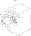
- Fig. 1 is a perspective view illustrating a drier according to an embodiment of the present invention
- Fig. 2 is a schematic view illustrating an internal configuration of a drier according to an embodiment of the present invention
- Fig. 3 is a configuration view illustrating a main configuration of a drier according to an embodiment of the present invention.
- a drier 1 may forms overall an outer appearance by a main body 10 which has an input port 11 for inputting clothes at one side and a door 20 which opens and closes the input port 11.
- a drum 15, which is rotatably installed and in which clothes are dried, may be provided inside the main body 10.
- the drum 15 is opened toward the input port 11 and can be provided to allow a user to input clothes into the drum 15 through the input port 11.
- the main body 10 may be provided with an operation unit 12 for operating the drier 1.
- the operation unit 12 may be located above the input port 11.
- the operation unit 12 may be provided with an operation button, a rotary switch, or the like for selecting a function provided to the drier 1.
- the user can operate the operation button or the rotary switch provided on the operating unit 12 to turn on or off the power of the drier 1, input an operation start or drive stop command, and set an operation mode, a drying time, and the like.
- the operation unit 12 may further include a display 13.
- the display 13 may output an operation state of the drier 1, a set operation mode, time information, and the like.
- a drawer 14 may be provided on one side of the main body 10, and liquid or the like to be sprayed onto the drum may be stored inside the drawer 14.
- the main body 10 may be provided with a driving motor 300 that provides rotation power to the drum 15.
- a power transmitting member 360 for rotating the drum 15 is provided on one rotation axis of the driving motor 300 and the drum is connected to the driving motor 300 by the power transmitting member 360 to be capable of receiving power.
- the power transmitting member 360 may be a pulley or a roller.
- the main body 10 may be provided with a supply flow path which supplies air heated to the drum 15 and a duct which forms an exhaust flow path through which the air inside the drum 15 is discharged.
- the duct may include a supply duct 30 which forms the supply flow path and an exhaust duct 40 which forms the exhaust flow path.
- the main body 10 may be provided with a blowing fan 50 for forcing the flow of air.
- the blowing fan 50 communicates with the supply duct 30 and the exhaust duct 40 and can force to supply air into the drum 15 through the supply duct 30 and to discharge air in the drum 15 through the discharge duct.
- the air blowing fan 50 is provided on the exhaust flow path so that the air discharged from the drum 15 can be sucked into the exhaust duct 40.
- the blowing fan 50 may be provided to be connected to the rotation shaft of the driving motor and to rotate simultaneously with the drum 15.
- the blowing fan 50 may be connected to a motor separate from the driving motor so as to be rotated independently of the drum 15.
- the embodiments of the present invention will be described with reference to a circulation type drier in which air in the drier is circulated, as an example.
- the present invention is not limited to the circulation type drier and can be applied to an exhaust type drier.
- the exhaust duct 40 may be provided to guide forced air to the supply duct 30.
- the exhaust duct 40 may be provided to guide the forced air to the outside.
- the supply duct 30 may extend to the rear side of the drum 15 and may have a discharge port through which heated air is discharged to the drum at an end portion thereof.
- the exhaust duct 40 extends to the front lower side of the drum 15, and a suction port through which the air inside the drum is sucked may be formed at an end portion thereof.
- a heater may be further provided on the supply flow path of the supply duct 30 to heat the supplied air by electric resistance heat. As the heater is provided, the heating properties of the supplied air can be further improved.
- a filter 45 may be provided on the exhaust flow path of the exhaust duct 40 to filter foreign matters such as lint contained in the air discharged from the drum 10.
- the main body 10 may be provided with a heat pump system 100 for absorbing waste heat from the air discharged from the drum 15 and heating the air supplied to the inside of the drum 15.
- the heat pump system 100 may include an evaporator 120 for cooling the air discharged from the inside of the drum 15, a compressor 110 for compressing the refrigerant, a condenser 130 for heating air supplied in the drum 15, and an expansion valve 140. According to this, the heat pump system 100 may constitute a thermodynamic cycle.
- the evaporator 120, the compressor 110, the condenser 130, and the expansion valve 140 may be sequentially connected by piping.
- the refrigerant can be circulated through the pipe.
- the refrigerant may be compressed by the compressor 110 to be in a gaseous state at a high temperature and a high pressure. Then, the refrigerant is in a high-temperature and high-pressure liquid state at the condenser 130 and can perform heat exchange with low-temperature air to be supplied to the drum 15. Then, the refrigerant can be expanded in the expansion valve 140 to become a low-temperature low-pressure gas state.
- the evaporator 120 can perform heat exchange with the hot and humid air discharged from the drum 15.
- the air supplied to the drum 15 can perform heat exchange in the condenser 130 and heated to a high temperature.
- the hot and humid air discharged from the drum 15 performs heat exchange in the evaporator 120, cooled, remove moisture, and become a dried state.
- the moisture contained in the hot and humid air can be condensed in the evaporator 120, collected as water, and can be discharged to the outside through a drain pipe (not illustrated).
- the evaporator 120 may be provided on an exhaust flow path of the exhaust duct 40.
- the condenser 130 may be provided on the supply flow path of the supply duct 30.
- a machine chamber communicating the exhaust duct 40 and the supply duct 30 with each other may be formed in the main body 10.
- the compressor 110 and the expansion valve 140 may be provided in the machine chamber.
- the driving motor may be also provided in the machine chamber.
- the drier 1 may further include a control unit 200 which controls the overall operation of the drier 1 and a memory 90 which stores information such as algorithm data and set value data related to the operation of the drier 1.
- the drier 1 may further include an outer air temperature sensor 70 for measuring an outer temperature and a compressor temperature sensor 80 for measuring the temperature of the compressor 110.
- the compressor temperature sensor 80 may be provided to measure the outlet side temperature of the compressor 110.
- the drier 1 may further include a humidity sensor 60.
- the humidity sensor 60 may be provided to measure the degree of drying of the object to be dried accommodated in the drum 15 or to detect whether or not wet clothes have been input. To this end, the humidity sensor 60 may be provided inside the drum 15.
- the operation unit 12, the driving motor, the compressor 110, the memory 90, the outer air temperature sensor 70, the compressor temperature sensor 80, and the humidity sensor 60 may be electrically connected to the control unit 200.
- the control unit 200 can detect an operation signal of the operation unit 12 and check information corresponding to the input operation signal from the memory 90. According to the information stored in the memory 90, the operation of the driving motor and the compressor 110 can be controlled. For example, when the drying start command is inputted from the operating unit 12, the control unit 200 drives the driving motor and the compressor 110 to start drying. When the drying termination command is inputted, the driving of the driving motor and the compressor 110 is stopped to terminate the drying.
- the control unit 200 may control the operation of the drier 1 according to information input from the outer air temperature sensor 70, the compressor temperature sensor 80 and the humidity sensor 60.
- control unit 200 may control the operation mode of the heat pump system 100 differently based on the temperature input from the outer air temperature sensor 70.
- the control unit 200 may switch the operation mode of the heat pump system 100 based on the temperature input from the compressor temperature sensor 80 or control the driving rotational speed of the compressor 110 to control the load. This will be described in more detail with reference to Fig. 4 .
- the control unit 200 determines whether or not wet clothing is input based on the humidity information input from the humidity sensor 60 and only in a case where the inputting of wet clothing is checked, the driving motor and the compressor 110 can be controlled so as to be operated. Then, the driving of the driving motor and the compressor 110 can be stopped by determining the drying state of the clothes based on the humidity information.
- control unit 200 lowers the rotation speed of the compressor 110 and the inside of the drum 15 be maintained at a temperature suitable for drying.
- the drier 1 is further provided with a separate temperature sensor for measuring the temperature inside the drum 15, and the control unit 200 can detect the temperature of the inside of the drum 15 through a temperature sensor which measures the temperature inside the drum 15.
- control unit 200 may determine whether or not the temperature inside the drum 15 has reached an appropriate temperature, based on the outlet side temperature of the compressor detected by the compressor temperature sensor 80.
- the compressor 110 may be a twin rotary type compressor.
- the twin-rotor compressor may have a structure in which two refrigerant compression chambers are vertically formed thereon and two eccentric rollers which are eccentrically rotated by a single drive shaft and compress the refrigerant are installed in the compression chamber so as to have a phase difference of 180 degrees.
- the twin rotary compressors have features in which the two eccentric rollers continuously compress refrigerant at the upper and lower portions to improve the compression efficiency of the compressor and reduce vibration and noise.
- the compressor 110 can reduce vibrations and noise while providing a higher compression efficiency as compared with a single type compressor having the same volume and only one compression chamber. Accordingly, it is possible to improve the drying performance of the drier 1 by providing a higher compression efficiency without further consuming a space for accommodating the compressor 110 in the drier 1.
- the compressor 110 can variably control the driving speed by the control unit 200, and the heating properties of the air can be controlled by varying the driving speed of the compressor 110.
- the control unit 200 may vary the operation frequency Hz of the compressor 110.
- the compressor 110 is applied to a twin rotary compressor, the noise can be reduced in the highfrequency range and the vibration can be reduced in the low-frequency range, as compared with the single type compression.
- the noise can be reduced in the highfrequency range and the vibration can be reduced in the low-frequency range, as compared with the single type compression.
- the frequency driving range of the compressor 110 can be variably controlled from a minimum of 30 Hz to a maximum of 90 Hz.
- R134a As the refrigerant used in the heat pump system 100 R134a can be applied.
- various fluids such as R245fa may be used as a refrigerant, but in the embodiment of the present invention, R134a refrigerant is applied as an example.
- the R134a refrigerant has a high discharge temperature characteristic, it is advantageous to heat the air supplied from the condenser 130 to the drum 15.
- the operation unit 12 may be provided with a mode selection unit 121 for selecting an operation mode of the drier 1 as an energy mode, a standard mode, and a speed mode.
- the energy mode is a mode for reducing power consumption, and the initial driving frequency of the compressor 110 may be the lowest mode among the operation modes.
- the standard mode may be a mode in which the initial driving frequency of the compressor 110 is higher than the energy mode and lower than the speed mode.
- the speed mode is a mode for maximizing the drying performance of the drier 1, and the initial driving frequency of the compressor 110 may be higher than the standard mode.
- the compressor 110 may be initially accelerated to 50 Hz. In a case where the compressor 110 is operated in the standard mode, the compressor 110 may be accelerated to an initial speed of 75 Hz. In a case where the compressor 110 is operated in the speed mode, the compressor 110 may be initially accelerated to 90 Hz.
- the energy mode, the spin mode, and the speed mode may have variable frequency sections of the compressor 110, respectively.
- the compressor 110 can be controlled so that the frequency is lowered to maintain the temperature inside the drum 15 when the temperature inside the drum 15 reaches a suitable temperature for drying.
- control unit 200 can determine whether or not the temperature inside the drum 15 has reached the suitable temperature based on the temperature measured by the compressor temperature sensor 80.
- control unit 200 may determine that the temperature inside the drum 15 has reached a suitable temperature when the temperature measured by the compressor temperature sensor 80 is 85 degrees. At this time, the temperature inside the drum 15 may be different according to the operation mode, and the speed mode may be the highest and the energy mode may be the lowest.
- the minimum frequency of the compressor 110 in the speed mode may be higher than the minimum frequency of the compressor 110 in the standard mode.
- the minimum frequency of the compressor 110 in the energy mode may be lower than the minimum frequency of the compressor 110 in the standard mode.
- the energy mode may be a mode in which the maximum frequency and the minimum frequency of the compressor 110 among the operation modes are the lowest.
- the speed mode may be a mode in which the maximum frequency and the minimum frequency of the compressor 110 are the highest among the operation modes.
- the frequency variable range of the compressor 110 in the energy mode may be 50 Hz-35 Hz.
- the frequency variable range of the compressor 110 in the standard mode may be 75 Hz-48 Hz.
- the frequency variable range of the compressor 110 in the speed mode may be 90 Hz-60 Hz.
- the user can select one of the energy mode, the standard mode, and the speed mode by operating the operation unit 12. For example, in a case where the power consumption is to be reduced, the energy mode can be selected, and in a case where the rapid drying is desired, the speed mode can be selected.
- the control unit 200 may control the heat pump system 100 differently according to the operation mode selected by the user.
- control unit 200 may determine as the low-temperature state and ignore the operation mode selected by the user and control the drier 1 to operate in the speed mode.
- control unit 200 may switch the drier 1 to the low-speed mode to prevent the compressor 110 from being damaged.
- the low-speed mode may be defined as a mode in which the frequency of the compressor 110 is lower than the minimum frequency of the current operation mode.
- the frequency of the compressor 110 may be controlled to be lower than 60 Hz, which is the minimum frequency of the speed mode when the low-speed mode is performed.
- the frequency of the compressor 110 may be controlled to be lower than 35 Hz, which is the minimum frequency of the energy mode, when the low-speed mode is performed.
- the frequency of the compressor 110 may be lower than 35 Hz, which is the minimum frequency of the energy mode.
- the frequency of the compressor can be lowered to at least 30Hz.
- the frequency of the compressor 110 may be controlled so as to be stepwise reduced to 30 Hz which is the minimum frequency of the low-speed mode of the compressor 110.
- it may be controlled so as to immediately decelerate to 30 Hz, which is the minimum frequency of the low-speed mode, and then maintain the minimum frequency.
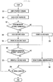
- Fig. 4 is a flowchart of a control method of the drier 1 according to the embodiment of the present invention.
- a user can input an operation command to the drier 1 by operating the operation unit 12. At this time, the user can select one of the energy mode, the standard mode, and the speed mode through the operation of the operation unit 12 [S10].
- the control unit 200 can check the outer temperature.
- the outer temperature can be measured at the outer air temperature sensor 70.
- the measured outer temperature may be transmitted to the control unit 200. Accordingly, the control unit 200 can detect the outer temperature [S20].
- the control unit 200 may compare the detected outer temperature with a reference temperature T, which is a preset temperature value. In detail, the control unit 200 may determine whether or not the detected outer temperature is equal to or more than, or less than the reference temperature T.
- the reference temperature T may be stored in the memory 90 and provided.
- the reference temperature T may be a temperature lower than 10 degrees and may be set to, for example, 5°C [S30].
- the control unit 200 can check the operation mode selected by the user. In other words, one of the energy mode, the standard mode, and the speed mode which is selected by the user can be checked [S40].
- control unit 200 can determine as the room temperature and operate the drier 1 in the operation mode selected by the user.
- the compressor 110 may be initially accelerated to 50 Hz to drive the heat pump system 100. Then, the blowing fan 50 and the drum 15 are operated to allow drying with low power consumption.
- the compressor 110 may be initially accelerated to 75 Hz to drive the heat pump system 100. Then, the blowing fan 50 and the drum 15 can be operated to perform drying.
- the compressor 110 may be initially accelerated to 90 Hz to drive the heat pump system 100.
- the blowing fan 50 and the drum 15 can be operated to increase the heating properties of the air supplied to the drum 15. According to this, drying can be performed rapidly.
- control unit 200 may lower stepwise the frequency of the compressor 110 to a predetermined level.
- control unit 200 compares the temperature measured by the compressor temperature sensor 80 with a preset reference temperature C2 and when the temperature measured by the compressor temperature sensor 80 reaches a reference temperature C2, can be determined that the inside of the drum 15 has reached the suitable temperature.
- the reference temperature C2 may be 85 degrees.
- the control unit 200 continuously checks the temperature measured by the compressor temperature sensor 80 at a predetermined cycle and lowers the frequency of the compressor 110 by a frequency reduction value H1 selected for each when the temperature reaches the reference temperature C2.
- the set frequency reduction value H1 may be 1 Hz.
- the frequency of the compressor 110 may be lowered to 35 Hz. In the standard mode, the frequency of the compressor 110 may be lowered to 48 Hz. In the speed mode, the frequency of the compressor 110 may be lowered to 60 Hz [S45].
- the control unit 200 may determine the driving environment of the drier 1 as a low-temperature condition. Accordingly, the control unit 200 can operate the drier 1 in the speed mode while ignoring the operation mode selected by the user. In other words, in a case where the outer temperature is equal to or less than the reference temperature T, the drier 1 can be operated in the speed mode even if the energy mode and the standard mode are selected by the user.
- control unit 200 may initially accelerate the compressor 110 to 90 Hz to drive the heat pump system 100.
- the drying operation can be rapidly performed by operating the blowing fan 50 and the drum 15 so as to increase the heating properties of air supplied to the drum 15.
- step S45 if the control unit determines that the internal temperature of the drum 15 has reached the suitable temperature for drying, the control unit 200 can decrease stepwise the frequency of the compressor 110 to a predetermined level [S50].
- the compressor 110 when the compressor 110 is overheated, the compressor 110 may be damaged.
- control unit 200 may determine whether the temperature of the compressor 110 is overheated.
- the control unit 200 may determine the overheated state of the compressor 110 through the surface temperature of the compressor 110 and in this case, a separate temperature sensor for measuring the surface temperature of the compressor 110 is further provided.
- control unit 200 may determine the overheating state of the compressor 110 through the outlet side temperature of the compressor 110 detected by the compressor temperature sensor 80.
- control unit 200 determines whether or not the compressor 110 is heated or overheated based on the outlet side temperature of the compressor 110 will be described.
- the control unit 200 can compare the temperature detected by the compressor temperature sensor 80 with the reference temperature C1 which is a preset temperature value and determine whether or not the outlet side temperature of the compressor 110 is equal to or more than, or less than the reference temperature C1.
- the reference temperature C1 may be stored in the memory 90 and provided and may be a temperature value higher than the reference temperature C2.
- the reference temperature C1 may be set to 95 degrees [S60].
- control unit 200 may perform a low-speed mode to prevent damage to the compressor 110 due to overheating.
- the low-speed mode may be defined as a mode of operating the frequency of the compressor 110 to be less than the minimum frequency of the current operation mode.
- the frequency of the compressor 110 may be controlled to be stepwise reduced to 30 Hz, which is the minimum frequency of the low-speed mode of the compressor 110.
- the frequency of the compressor may be controlled to immediately decelerate to 30 Hz, which is the minimum frequency of the low-speed mode, and then maintain the minimum frequency.
- the control unit 200 can continuously check the outlet side temperature of the compressor 110 at a predetermined cycle.
- the frequency of the compressor 110 may be lowered by a set frequency reduction value H2.
- the set frequency reduction value H2 may be 5 Hz [S70].
- the control unit 200 can control the drier 1 to continuously operate in the initial operation mode in which the drier 1 is in operation.
- the initial operation mode may be one of the energy mode, the standard mode, and the speed mode, as an operation mode at the time of driving state of the drier 1.
- control unit 200 can continuously check the outlet side temperature of the compressor 110 even after the low-speed mode is performed.
- the control unit 200 allows the drier 1 to be released from the low-speed mode and to be returned to the initial operation mode before the low-speed mode is performed [S80].
- the control unit 200 may stop the driving of the drum 15 and the compressor 110 when the drying of the input cloth is completed [S90].
- the control unit determines that the operating environment of the drier is in a low-temperature, ignores the operation mode selected by the user, forcibly performs the operation mode in which the initial driving frequency of the compressor of the plurality of operation modes. Therefore, in a situation where the outer temperature is low, the heat pump system can achieve sufficient heating properties, thereby preventing an excessive drying time from being generated. Therefore, it is possible to prevent the generation of the user complaints about the performance of the drier.
- the control unit checks the outlet side temperature of the compressor, and in a case where the outlet side temperature of the compressor is more than the reference temperature C1, the control unit determines that the compressor is overloaded and performs the low-speed mode. At this time, since the low-speed mode decelerates the compressor to a frequency less than the variable minimum frequency of the compressor in the operation mode being performed, the load of the compressor is reduced. Thus, the compressor can be prevented from being damaged by the high temperature.
- the lowest frequency of the compressor in the low-speed mode is larger than 0Hz.
- the compressor is operated at a low-speed in a state where the compressor is overloaded, so that the air can be continuously heated. Therefore, drying performance can be improved.
- the control unit checks the outlet side temperature of the compressor at a constant cycle and decreases stepwise the outlet side temperature of the compressor. Therefore, the compressor is rapidly cooled, the heating properties are prevented from being lowered, and the optimum performance can be achieved while reducing the load.
- compressors are applied as twin rotary compressors, vibration and noise at high and low frequencies can be minimized.
- the maximum frequency and minimum frequency range of the compressor can be expanded while maintaining vibration and noise levels at customer satisfaction levels. Therefore, it is possible to further secure a frequency range of the low-speed mode in which the lowest frequency is less than the operation mode.
- the maximum frequency can increase, the drying performance can be further improved.
Landscapes
- Engineering & Computer Science (AREA)
- Textile Engineering (AREA)
- Control Of Washing Machine And Dryer (AREA)
- Detail Structures Of Washing Machines And Dryers (AREA)
Claims (14)
- Procédé de commande d'un sèche-linge (1) comprenant une carrosserie principale (10) où est formée une ouverture de chargement (11) ; un tambour (15) monté de manière rotative dans la carrosserie principale (10) ; un moteur d'entraînement (300) transmettant une puissance de rotation au tambour (15) ; un ventilateur de soufflage (50) refoulant un flux d'air vers la carrosserie principale (10) ; un système de pompe à chaleur (100) comprenant un condensateur (130), un évaporateur (120) et un compresseur (110) de manière à chauffer l'air refoulé vers le tambour (15) ; et une unité de commande (200) commandant un mode de fonctionnement, comprenant :l'entrée (S10) d'une instruction de déclenchement du séchage par sélection d'un mode parmi une pluralité de modes de fonctionnement où des fréquences variables du compresseur (110) définies dans une plage allant d'une fréquence minimale à une fréquence maximale et des fréquences d'excitation initiales du compresseur (110) diffèrent les unes des autres ;la comparaison (S30) par l'unité de commande (200) d'une température extérieure détectée sur un capteur de température (70) d'air extérieur avec une température de référence prédéfinie T ;la détermination comme état de température ambiante d'un environnement d'entraînement du sèche-linge (1) et le lancement (S45) du premier mode de fonctionnement sélectionné si la température extérieure est égale ou supérieure à la température de référence T;la détermination comme état de température basse (S50) de l'environnement d'entraînement du sèche-linge (1) si la température extérieure est inférieure à la température de référence T ;en état de température basse, le délaissement du premier mode de fonctionnement sélectionné et le lancement forcé d'un mode de fonctionnement où la fréquence d'excitation initiale, la fréquence minimale et la fréquence maximale du compresseur (110) sont les plus élevées parmi la pluralité de modes de fonctionnement (S50) ; etla détection d'une température côté sortie du compresseur (110) pour déterminer si le compresseur (100) est en état de surcharge.
- Procédé de commande d'un sèche-linge (1) selon la revendication 1, comprenant en outre :la comparaison (S60) de la température côté sortie du compresseur (110) détectée par un capteur de température (80) de compresseur prévu sur un côté sortie du compresseur (110) avec une première température de référence prédéfinie C1; etla détermination que le compresseur (110) est en état de surcharge et le lancement (S70) d'un mode à faible vitesse où le compresseur (110) est entraîné à une fréquence inférieure à la fréquence minimale d'un mode de fonctionnement en cours, si la température côté sortie du compresseur (110) est égale ou supérieure à la première température de référence C1.
- Procédé de commande d'un sèche-linge (1) selon la revendication 1 ou la revendication 2,
où la pluralité de modes de fonctionnement comprend
un mode de vitesse où la fréquence d'excitation initiale, la fréquence maximale et la fréquence minimale du compresseur (110) sont maximales ;
un mode d'énergie où la fréquence d'excitation initiale, la fréquence maximale et la fréquence minimale du compresseur (110) sont minimales ; et
un mode standard où la fréquence d'excitation initiale, la fréquence maximale et la fréquence minimale du compresseur (110) sont respectivement inférieures au mode de vitesse et supérieures au mode d'énergie. - Procédé de commande d'un sèche-linge (1) selon l'une des revendications 1 à 3, comprenant en outre :la détermination d'un état de séchage des vêtements sur la base d'une information d'humidité détectée par un capteur d'humidité prévu à l'intérieur du tambour (15) ; etl'arrêt de l'entraînement du tambour (15) et du compresseur (110) à l'issue du séchage des vêtements.
- Procédé de commande d'un sèche-linge (1) selon l'une des revendications 2 à 4,
où, en mode à faible vitesse, la fréquence variable est inférieure à la fréquence minimale de la pluralité des modes de fonctionnement. - Procédé de commande d'un sèche-linge (1) selon l'une des revendications 2 à 5,
où la fréquence variable est supérieure à 0 Hz. - Procédé de commande d'un sèche-linge (1) selon l'une des revendications 2 à 6,
où l'unité de commande (200) annule le mode à faible vitesse et retourne au mode de fonctionnement avant le lancement du mode à faible vitesse, si la température côté sortie du compresseur (110) est inférieure à la première température de référence C1 pendant l'exécution du mode à faible vitesse. - Procédé de commande d'un sèche-linge (1) selon l'une des revendications 2 à 7,
où, en mode à faible vitesse, l'unité de commande (200) contrôle la température côté sortie du compresseur (110) suivant un cycle prédéfini et diminue graduellement la fréquence du compresseur (110) d'une deuxième valeur de diminution de fréquence définie H2. - Procédé de commande d'un sèche-linge (1) selon l'une des revendications 2 à 8, comprenant en outre :la détermination si la température à l'intérieur du tambour (15) atteint un niveau de température adapté au séchage par comparaison par l'unité de commande (200) de la température côté sortie du compresseur (110) avec une deuxième température de référence prédéfinie C2, dans un état où un mode de la pluralité de modes de fonctionnement est lancé ; etla diminution de la fréquence du compresseur (110), de telle manière que l'unité de commande (200) détermine que la température à l'intérieur du tambour (15) atteint une température adaptée au séchage et maintient la température, si la température côté sortie du compresseur (110) est égale ou supérieure à la deuxième température de référence C2.
- Procédé de commande d'un sèche-linge (1) selon la revendication 9, où l'unité de commande (200) contrôle suivant un cycle (110) prédéfini si la température côté sortie du compresseur (110) est égale ou supérieure à la deuxième température de référence C2 et diminue graduellement la fréquence du compresseur (110) d'une première valeur de diminution de fréquence définie H1, dans un état où un mode de la pluralité de modes de fonctionnement est lancé.
- Procédé de commande d'un sèche-linge (1) selon la revendication 10, où la deuxième valeur de diminution de fréquence H2 est supérieure à la première valeur de diminution de fréquence H1.
- Procédé de commande d'un sèche-linge (1) selon l'une des revendications 1 à 11, où le compresseur (110) est un compresseur rotatif double.
- Procédé de commande d'un sèche-linge (1) selon l'une des revendications 1 à 12, où un réfrigérant R134a est utilisé comme réfrigérant du système de pompe à chaleur (100).
- Procédé de commande d'un sèche-linge (1) selon l'une des revendications 1 à 13, où ledit sèche-linge (1) comprend en outre :une conduite de refoulement (30) communiquant avec le ventilateur de soufflage (50) et conduisant de l'air chauffé vers le tambour (15) ; etune conduite d'échappement communiquant avec le ventilateur de soufflage (50) et aspirant de l'air dans le tambour (15),le condensateur (130) présentant un chemin d'écoulement de refoulement de la conduite de refoulement (30), l'évaporateur (120) présentant un chemin d'écoulement d'échappement de la conduite d'échappement.
Priority Applications (1)
| Application Number | Priority Date | Filing Date | Title |
|---|---|---|---|
| EP20185686.1A EP3754095B1 (fr) | 2017-11-20 | 2018-11-19 | Sèche-linge |
Applications Claiming Priority (1)
| Application Number | Priority Date | Filing Date | Title |
|---|---|---|---|
| KR1020170154928A KR102408516B1 (ko) | 2017-11-20 | 2017-11-20 | 건조기의 제어방법 |
Related Child Applications (2)
| Application Number | Title | Priority Date | Filing Date |
|---|---|---|---|
| EP20185686.1A Division-Into EP3754095B1 (fr) | 2017-11-20 | 2018-11-19 | Sèche-linge |
| EP20185686.1A Division EP3754095B1 (fr) | 2017-11-20 | 2018-11-19 | Sèche-linge |
Publications (2)
| Publication Number | Publication Date |
|---|---|
| EP3495548A1 EP3495548A1 (fr) | 2019-06-12 |
| EP3495548B1 true EP3495548B1 (fr) | 2020-09-16 |
Family
ID=64362411
Family Applications (2)
| Application Number | Title | Priority Date | Filing Date |
|---|---|---|---|
| EP20185686.1A Active EP3754095B1 (fr) | 2017-11-20 | 2018-11-19 | Sèche-linge |
| EP18206984.9A Active EP3495548B1 (fr) | 2017-11-20 | 2018-11-19 | Procédé de commande de sèche-linge |
Family Applications Before (1)
| Application Number | Title | Priority Date | Filing Date |
|---|---|---|---|
| EP20185686.1A Active EP3754095B1 (fr) | 2017-11-20 | 2018-11-19 | Sèche-linge |
Country Status (5)
| Country | Link |
|---|---|
| US (2) | US10947661B2 (fr) |
| EP (2) | EP3754095B1 (fr) |
| KR (2) | KR102408516B1 (fr) |
| CN (2) | CN115216952A (fr) |
| WO (1) | WO2019098636A1 (fr) |
Families Citing this family (5)
| Publication number | Priority date | Publication date | Assignee | Title |
|---|---|---|---|---|
| WO2019108005A1 (fr) * | 2017-12-01 | 2019-06-06 | 엘지전자 주식회사 | Sèche-linge et son procédé de commande |
| US20210290000A1 (en) * | 2020-03-19 | 2021-09-23 | Lg Electronics Inc. | Drying apparatus and related methods |
| US11319661B1 (en) * | 2020-12-22 | 2022-05-03 | Whirlpool Corporation | Ventilation solution for closed-loop dryer systems |
| KR20230095422A (ko) * | 2021-12-22 | 2023-06-29 | 삼성전자주식회사 | 의류 건조기 및 결빙 방지 구동 방법 |
| CN115507502A (zh) * | 2022-09-23 | 2022-12-23 | 青岛海尔空调器有限总公司 | 用于控制空调的方法、装置及空调 |
Family Cites Families (55)
| Publication number | Priority date | Publication date | Assignee | Title |
|---|---|---|---|---|
| DE3015428C2 (de) * | 1980-04-22 | 1982-04-22 | Ranco Inc., 43201 Columbus, Ohio | Trommeltrockner zum Trocknen von Wäsche |
| KR940006249B1 (ko) * | 1991-11-18 | 1994-07-13 | 주식회사 금성사 | 의류건조기의 건조시간 설정방법 |
| US7191543B2 (en) * | 2003-04-02 | 2007-03-20 | Matsushita Electric Industrial Co., Ltd. | Drying device and method of operation therefor |
| US20060048405A1 (en) * | 2003-05-23 | 2006-03-09 | Baek Seung M | Drum type washing machine and dryer and method for automatic drying by using the same |
| CN100453942C (zh) * | 2003-09-25 | 2009-01-21 | 松下电器产业株式会社 | 热泵型干燥装置、干燥装置及干燥方法 |
| WO2005032322A2 (fr) * | 2003-09-29 | 2005-04-14 | Self Propelled Research And Development Specialists, Llc | Seche-linge a pompe a chaleur |
| EP1584731A3 (fr) * | 2004-03-15 | 2007-11-14 | SANYO ELECTRIC Co., Ltd. | Machine à nettoyer les vêtements à sec et sèche-linge correspondant |
| CN100453922C (zh) * | 2004-04-09 | 2009-01-21 | 松下电器产业株式会社 | 干燥装置 |
| KR100577248B1 (ko) * | 2004-06-14 | 2006-05-10 | 엘지전자 주식회사 | 건조장치 및 건조장치의 건조행정 제어방법 |
| KR100565338B1 (ko) * | 2004-08-12 | 2006-03-30 | 엘지전자 주식회사 | 용량가변형 복식 로터리 압축기 및 그 운전 방법 및 이를 구비한 에어콘 및 그 운전 방법 |
| JP4266903B2 (ja) * | 2004-09-07 | 2009-05-27 | 三洋電機株式会社 | 洗濯乾燥機 |
| JP4108072B2 (ja) * | 2004-09-07 | 2008-06-25 | 三洋電機株式会社 | 乾燥機 |
| US7082695B1 (en) * | 2005-01-24 | 2006-08-01 | King-Leung Wong | Power-saving drying machine control |
| JP4661590B2 (ja) * | 2005-12-27 | 2011-03-30 | パナソニック株式会社 | 洗濯乾燥機のモータ駆動装置 |
| KR101253151B1 (ko) * | 2006-04-17 | 2013-04-10 | 엘지전자 주식회사 | 건조기의 화재감지 방법 |
| KR101253641B1 (ko) * | 2006-04-17 | 2013-04-10 | 엘지전자 주식회사 | 건조장치 및 그 제어 방법 |
| CN101713141B (zh) * | 2008-09-30 | 2011-12-07 | 三洋电机株式会社 | 热泵式干燥机 |
| JP5274184B2 (ja) * | 2008-09-30 | 2013-08-28 | 三洋電機株式会社 | ヒートポンプ式乾燥機 |
| JP2010104579A (ja) * | 2008-10-30 | 2010-05-13 | Toshiba Corp | 洗濯機 |
| DE202010018225U1 (de) * | 2009-10-27 | 2014-10-23 | Panasonic Corp. | Wäschetrockner und Waschtrockner |
| EP2565320B1 (fr) * | 2010-04-28 | 2018-04-11 | LG Electronics Inc. | Appareil de traitement de linge |
| US20110280736A1 (en) * | 2010-04-28 | 2011-11-17 | Lee Yongju | Control method of dryer |
| WO2011136592A2 (fr) * | 2010-04-28 | 2011-11-03 | 엘지전자 주식회사 | Procédé de commande d'un séchoir |
| WO2012044038A2 (fr) * | 2010-09-30 | 2012-04-05 | Lg Electronics Inc. | Procédé de diagnostic pour des appareils de traitement de linge et appareil de traitement de linge pourvu d'un moyen de détection de fuite d'un fluide réfrigérant |
| KR101224054B1 (ko) * | 2010-09-30 | 2013-01-22 | 엘지전자 주식회사 | 의류처리장치 및 의류처리장치의 운전방법 |
| EP2460927B1 (fr) * | 2010-12-02 | 2014-02-26 | Electrolux Home Products Corporation N.V. | Procédé de fonctionnement de séchoir à pompe thermique et séchoir à pompe thermique |
| EP2460926A1 (fr) * | 2010-12-02 | 2012-06-06 | Electrolux Home Products Corporation N.V. | Séchoir à pompe thermique |
| EP2460928B1 (fr) * | 2010-12-02 | 2014-02-26 | Electrolux Home Products Corporation N.V. | Procédé de fonctionnement d'un séchoir à pompe à chaleur et séchoir à pompe à chaleur |
| JP2012125352A (ja) * | 2010-12-14 | 2012-07-05 | Samsung Electronics Co Ltd | 衣類乾燥機 |
| KR101921069B1 (ko) * | 2012-03-06 | 2018-11-22 | 엘지전자 주식회사 | 건조기의 제어방법 |
| KR20120110500A (ko) * | 2011-03-29 | 2012-10-10 | 엘지전자 주식회사 | 의류처리장치의 진단방법 |
| EP2691568B1 (fr) * | 2011-03-29 | 2017-12-27 | LG Electronics Inc. | Procédé de commande destiné à un sèche-linge |
| US9417009B2 (en) * | 2012-03-06 | 2016-08-16 | Lg Electronics Inc. | Controlling method for a washing machine |
| JP2014018452A (ja) * | 2012-07-19 | 2014-02-03 | Panasonic Corp | ドラム式乾燥機 |
| KR102009277B1 (ko) * | 2012-10-22 | 2019-08-09 | 엘지전자 주식회사 | 히트펌프를 구비한 의류처리장치 및 그 제어방법 |
| EP2733252A1 (fr) * | 2012-11-16 | 2014-05-21 | Electrolux Home Products Corporation N.V. | Procédé d'utilisation d'un sèche-linge avec pompe à chaleur, sèche-linge avec pompe à chaleur ou machine à laver avec pompe à chaleur ayant une fonction de séchage |
| CN103882665B (zh) * | 2012-12-21 | 2018-03-30 | 青岛海尔洗衣机有限公司 | 一种热泵干衣机变频压缩机的控制方法及热泵干衣机 |
| KR101579655B1 (ko) * | 2013-01-21 | 2015-12-22 | 가부시끼가이샤 도시바 | 의류 건조기 및 컴프레서 구동장치 |
| KR102058995B1 (ko) * | 2013-02-28 | 2019-12-24 | 엘지전자 주식회사 | 의류처리장치 및 이의 제어방법 |
| KR102025181B1 (ko) * | 2013-04-03 | 2019-09-26 | 삼성전자주식회사 | 의류 건조기 및 그 제어방법 |
| JP6092004B2 (ja) * | 2013-06-03 | 2017-03-08 | 東芝ライフスタイル株式会社 | 衣類乾燥機 |
| US9879372B2 (en) * | 2013-06-18 | 2018-01-30 | Samsung Electronics Co., Ltd. | Clothes dryer |
| PL2845943T3 (pl) * | 2013-09-10 | 2021-10-25 | Electrolux Appliances Aktiebolag | Sposób obsługiwania silnika o zmiennej prędkości w aparacie pralniczym |
| CN104631069A (zh) * | 2013-11-07 | 2015-05-20 | 杭州三花研究院有限公司 | 干衣机及其控制方法 |
| US9670612B2 (en) * | 2014-08-13 | 2017-06-06 | Lg Electronics Inc. | Laundry treatment apparatus and method for controlling a laundry treatment apparatus |
| DE102014218254A1 (de) * | 2014-09-11 | 2016-03-17 | BSH Hausgeräte GmbH | Kondensationstrockner mit einem Temperatursensor, sowie Verfahren zu seinem Betreiben |
| KR101613962B1 (ko) * | 2014-11-20 | 2016-04-20 | 엘지전자 주식회사 | 히트펌프 사이클을 구비한 의류처리장치 및 이의 제어방법 |
| CN105839375A (zh) * | 2015-01-12 | 2016-08-10 | 青岛海尔洗衣机有限公司 | 一种干衣机控制方法及干衣机 |
| WO2016204415A1 (fr) * | 2015-06-19 | 2016-12-22 | 엘지전자 주식회사 | Sèche-linge et son procédé de commande |
| CN106592185A (zh) * | 2015-10-20 | 2017-04-26 | 杭州三花家电热管理系统有限公司 | 烘干装置、烘干装置的控制方法及控制系统 |
| CN107841861B (zh) * | 2016-09-19 | 2020-05-05 | 青岛海尔滚筒洗衣机有限公司 | 一种干衣机控制方法 |
| KR102658780B1 (ko) * | 2016-09-21 | 2024-04-19 | 엘지전자 주식회사 | 건조기의 제어 방법 |
| US10181245B2 (en) * | 2016-12-29 | 2019-01-15 | Nortek Security & Control Llc | Dryer vent monitoring device |
| KR102364677B1 (ko) * | 2017-03-20 | 2022-02-18 | 엘지전자 주식회사 | 의류처리장치의 제어방법 |
| KR102432108B1 (ko) * | 2017-10-26 | 2022-08-16 | 삼성전자주식회사 | 건조 기기 및 이를 제어하는 방법 |
-
2017
- 2017-11-20 KR KR1020170154928A patent/KR102408516B1/ko active IP Right Grant
-
2018
- 2018-11-13 CN CN202210896829.9A patent/CN115216952A/zh active Pending
- 2018-11-13 CN CN201880073441.0A patent/CN111344450B/zh active Active
- 2018-11-13 WO PCT/KR2018/013777 patent/WO2019098636A1/fr active Application Filing
- 2018-11-19 EP EP20185686.1A patent/EP3754095B1/fr active Active
- 2018-11-19 EP EP18206984.9A patent/EP3495548B1/fr active Active
- 2018-11-20 US US16/196,417 patent/US10947661B2/en active Active
-
2021
- 2021-01-22 US US17/155,883 patent/US20210140092A1/en active Pending
-
2022
- 2022-03-15 KR KR1020220031999A patent/KR20220039682A/ko not_active Application Discontinuation
Non-Patent Citations (1)
| Title |
|---|
| None * |
Also Published As
| Publication number | Publication date |
|---|---|
| KR20220039682A (ko) | 2022-03-29 |
| KR102408516B1 (ko) | 2022-06-13 |
| CN115216952A (zh) | 2022-10-21 |
| US20210140092A1 (en) | 2021-05-13 |
| EP3754095A1 (fr) | 2020-12-23 |
| US20190153658A1 (en) | 2019-05-23 |
| US10947661B2 (en) | 2021-03-16 |
| WO2019098636A1 (fr) | 2019-05-23 |
| KR20190057682A (ko) | 2019-05-29 |
| CN111344450A (zh) | 2020-06-26 |
| CN111344450B (zh) | 2022-08-19 |
| EP3754095B1 (fr) | 2022-03-16 |
| EP3495548A1 (fr) | 2019-06-12 |
Similar Documents
| Publication | Publication Date | Title |
|---|---|---|
| EP3495548B1 (fr) | Procédé de commande de sèche-linge | |
| US10273628B2 (en) | Control method for laundry drying machine | |
| EP2935687B1 (fr) | Procédé pour commander un sèche-linge et sèche-linge correspondant | |
| WO2011052154A1 (fr) | Sèche-linge et machine à laver/sèche-linge | |
| US8595954B2 (en) | Clothes treating apparatus with heat pump system and operating method thereof | |
| EP2935686B1 (fr) | Procédé pour commander un système de pompe à chaleur pour un sèche-linge et sèche-linge correspondant | |
| CN106592185A (zh) | 烘干装置、烘干装置的控制方法及控制系统 | |
| KR102058995B1 (ko) | 의류처리장치 및 이의 제어방법 | |
| WO2015082011A1 (fr) | Procédé permettant de commander un sèche-linge du type comprenant un système de pompe à chaleur, et sèche-linge correspondant | |
| JP6486197B2 (ja) | 衣類乾燥機 | |
| KR20210062210A (ko) | 건조기 및 그 제어 방법 | |
| JP4984924B2 (ja) | 衣類乾燥装置および同装置を備えた洗濯乾燥機 | |
| JP5925999B2 (ja) | 衣類乾燥装置 | |
| JP5397155B2 (ja) | 衣類乾燥機 | |
| JP2013017639A (ja) | 衣類乾燥装置 | |
| JP6685180B2 (ja) | 洗濯乾燥機 | |
| JP6466093B2 (ja) | 衣類乾燥機 | |
| JP2011092247A (ja) | 衣類乾燥機および洗濯乾燥機 | |
| KR20190057659A (ko) | 건조기의 제어 방법 | |
| JP2011092248A (ja) | 衣類乾燥機および洗濯乾燥機 | |
| JP4939792B2 (ja) | 衣類乾燥機 | |
| JP2016052450A (ja) | 洗濯乾燥機 |
Legal Events
| Date | Code | Title | Description |
|---|---|---|---|
| PUAI | Public reference made under article 153(3) epc to a published international application that has entered the european phase |
Free format text: ORIGINAL CODE: 0009012 |
|
| STAA | Information on the status of an ep patent application or granted ep patent |
Free format text: STATUS: REQUEST FOR EXAMINATION WAS MADE |
|
| 17P | Request for examination filed |
Effective date: 20181219 |
|
| AK | Designated contracting states |
Kind code of ref document: A1 Designated state(s): AL AT BE BG CH CY CZ DE DK EE ES FI FR GB GR HR HU IE IS IT LI LT LU LV MC MK MT NL NO PL PT RO RS SE SI SK SM TR |
|
| AX | Request for extension of the european patent |
Extension state: BA ME |
|
| RBV | Designated contracting states (corrected) |
Designated state(s): AL AT BE BG CH CY CZ DE DK EE ES FI FR GB GR HR HU IE IS IT LI LT LU LV MC MK MT NL NO PL PT RO RS SE SI SK SM TR |
|
| REG | Reference to a national code |
Ref country code: DE Ref legal event code: R079 Ref document number: 602018007868 Country of ref document: DE Free format text: PREVIOUS MAIN CLASS: D06F0058280000 Ipc: D06F0058380000 |
|
| GRAP | Despatch of communication of intention to grant a patent |
Free format text: ORIGINAL CODE: EPIDOSNIGR1 |
|
| STAA | Information on the status of an ep patent application or granted ep patent |
Free format text: STATUS: GRANT OF PATENT IS INTENDED |
|
| RIC1 | Information provided on ipc code assigned before grant |
Ipc: D06F 58/38 20200101AFI20200225BHEP |
|
| INTG | Intention to grant announced |
Effective date: 20200326 |
|
| RAP1 | Party data changed (applicant data changed or rights of an application transferred) |
Owner name: LG ELECTRONICS INC. |
|
| RIN1 | Information on inventor provided before grant (corrected) |
Inventor name: LEE, INGEON Inventor name: JE, HAEYOON |
|
| GRAS | Grant fee paid |
Free format text: ORIGINAL CODE: EPIDOSNIGR3 |
|
| GRAA | (expected) grant |
Free format text: ORIGINAL CODE: 0009210 |
|
| STAA | Information on the status of an ep patent application or granted ep patent |
Free format text: STATUS: THE PATENT HAS BEEN GRANTED |
|
| AK | Designated contracting states |
Kind code of ref document: B1 Designated state(s): AL AT BE BG CH CY CZ DE DK EE ES FI FR GB GR HR HU IE IS IT LI LT LU LV MC MK MT NL NO PL PT RO RS SE SI SK SM TR |
|
| REG | Reference to a national code |
Ref country code: GB Ref legal event code: FG4D |
|
| REG | Reference to a national code |
Ref country code: CH Ref legal event code: EP |
|
| REG | Reference to a national code |
Ref country code: DE Ref legal event code: R096 Ref document number: 602018007868 Country of ref document: DE |
|
| REG | Reference to a national code |
Ref country code: IE Ref legal event code: FG4D |
|
| REG | Reference to a national code |
Ref country code: AT Ref legal event code: REF Ref document number: 1314268 Country of ref document: AT Kind code of ref document: T Effective date: 20201015 |
|
| PG25 | Lapsed in a contracting state [announced via postgrant information from national office to epo] |
Ref country code: GR Free format text: LAPSE BECAUSE OF FAILURE TO SUBMIT A TRANSLATION OF THE DESCRIPTION OR TO PAY THE FEE WITHIN THE PRESCRIBED TIME-LIMIT Effective date: 20201217 Ref country code: SE Free format text: LAPSE BECAUSE OF FAILURE TO SUBMIT A TRANSLATION OF THE DESCRIPTION OR TO PAY THE FEE WITHIN THE PRESCRIBED TIME-LIMIT Effective date: 20200916 Ref country code: HR Free format text: LAPSE BECAUSE OF FAILURE TO SUBMIT A TRANSLATION OF THE DESCRIPTION OR TO PAY THE FEE WITHIN THE PRESCRIBED TIME-LIMIT Effective date: 20200916 Ref country code: FI Free format text: LAPSE BECAUSE OF FAILURE TO SUBMIT A TRANSLATION OF THE DESCRIPTION OR TO PAY THE FEE WITHIN THE PRESCRIBED TIME-LIMIT Effective date: 20200916 Ref country code: BG Free format text: LAPSE BECAUSE OF FAILURE TO SUBMIT A TRANSLATION OF THE DESCRIPTION OR TO PAY THE FEE WITHIN THE PRESCRIBED TIME-LIMIT Effective date: 20201216 Ref country code: NO Free format text: LAPSE BECAUSE OF FAILURE TO SUBMIT A TRANSLATION OF THE DESCRIPTION OR TO PAY THE FEE WITHIN THE PRESCRIBED TIME-LIMIT Effective date: 20201216 |
|
| REG | Reference to a national code |
Ref country code: AT Ref legal event code: MK05 Ref document number: 1314268 Country of ref document: AT Kind code of ref document: T Effective date: 20200916 |
|
| REG | Reference to a national code |
Ref country code: NL Ref legal event code: MP Effective date: 20200916 |
|
| PG25 | Lapsed in a contracting state [announced via postgrant information from national office to epo] |
Ref country code: RS Free format text: LAPSE BECAUSE OF FAILURE TO SUBMIT A TRANSLATION OF THE DESCRIPTION OR TO PAY THE FEE WITHIN THE PRESCRIBED TIME-LIMIT Effective date: 20200916 Ref country code: LV Free format text: LAPSE BECAUSE OF FAILURE TO SUBMIT A TRANSLATION OF THE DESCRIPTION OR TO PAY THE FEE WITHIN THE PRESCRIBED TIME-LIMIT Effective date: 20200916 |
|
| REG | Reference to a national code |
Ref country code: LT Ref legal event code: MG4D |
|
| PG25 | Lapsed in a contracting state [announced via postgrant information from national office to epo] |
Ref country code: EE Free format text: LAPSE BECAUSE OF FAILURE TO SUBMIT A TRANSLATION OF THE DESCRIPTION OR TO PAY THE FEE WITHIN THE PRESCRIBED TIME-LIMIT Effective date: 20200916 Ref country code: RO Free format text: LAPSE BECAUSE OF FAILURE TO SUBMIT A TRANSLATION OF THE DESCRIPTION OR TO PAY THE FEE WITHIN THE PRESCRIBED TIME-LIMIT Effective date: 20200916 Ref country code: PT Free format text: LAPSE BECAUSE OF FAILURE TO SUBMIT A TRANSLATION OF THE DESCRIPTION OR TO PAY THE FEE WITHIN THE PRESCRIBED TIME-LIMIT Effective date: 20210118 Ref country code: CZ Free format text: LAPSE BECAUSE OF FAILURE TO SUBMIT A TRANSLATION OF THE DESCRIPTION OR TO PAY THE FEE WITHIN THE PRESCRIBED TIME-LIMIT Effective date: 20200916 Ref country code: LT Free format text: LAPSE BECAUSE OF FAILURE TO SUBMIT A TRANSLATION OF THE DESCRIPTION OR TO PAY THE FEE WITHIN THE PRESCRIBED TIME-LIMIT Effective date: 20200916 Ref country code: SM Free format text: LAPSE BECAUSE OF FAILURE TO SUBMIT A TRANSLATION OF THE DESCRIPTION OR TO PAY THE FEE WITHIN THE PRESCRIBED TIME-LIMIT Effective date: 20200916 |
|
| PG25 | Lapsed in a contracting state [announced via postgrant information from national office to epo] |
Ref country code: IS Free format text: LAPSE BECAUSE OF FAILURE TO SUBMIT A TRANSLATION OF THE DESCRIPTION OR TO PAY THE FEE WITHIN THE PRESCRIBED TIME-LIMIT Effective date: 20210116 Ref country code: PL Free format text: LAPSE BECAUSE OF FAILURE TO SUBMIT A TRANSLATION OF THE DESCRIPTION OR TO PAY THE FEE WITHIN THE PRESCRIBED TIME-LIMIT Effective date: 20200916 Ref country code: AT Free format text: LAPSE BECAUSE OF FAILURE TO SUBMIT A TRANSLATION OF THE DESCRIPTION OR TO PAY THE FEE WITHIN THE PRESCRIBED TIME-LIMIT Effective date: 20200916 Ref country code: AL Free format text: LAPSE BECAUSE OF FAILURE TO SUBMIT A TRANSLATION OF THE DESCRIPTION OR TO PAY THE FEE WITHIN THE PRESCRIBED TIME-LIMIT Effective date: 20200916 Ref country code: ES Free format text: LAPSE BECAUSE OF FAILURE TO SUBMIT A TRANSLATION OF THE DESCRIPTION OR TO PAY THE FEE WITHIN THE PRESCRIBED TIME-LIMIT Effective date: 20200916 |
|
| REG | Reference to a national code |
Ref country code: DE Ref legal event code: R097 Ref document number: 602018007868 Country of ref document: DE |
|
| PG25 | Lapsed in a contracting state [announced via postgrant information from national office to epo] |
Ref country code: SK Free format text: LAPSE BECAUSE OF FAILURE TO SUBMIT A TRANSLATION OF THE DESCRIPTION OR TO PAY THE FEE WITHIN THE PRESCRIBED TIME-LIMIT Effective date: 20200916 Ref country code: MC Free format text: LAPSE BECAUSE OF FAILURE TO SUBMIT A TRANSLATION OF THE DESCRIPTION OR TO PAY THE FEE WITHIN THE PRESCRIBED TIME-LIMIT Effective date: 20200916 |
|
| PLBE | No opposition filed within time limit |
Free format text: ORIGINAL CODE: 0009261 |
|
| STAA | Information on the status of an ep patent application or granted ep patent |
Free format text: STATUS: NO OPPOSITION FILED WITHIN TIME LIMIT |
|
| PG25 | Lapsed in a contracting state [announced via postgrant information from national office to epo] |
Ref country code: LU Free format text: LAPSE BECAUSE OF NON-PAYMENT OF DUE FEES Effective date: 20201119 |
|
| REG | Reference to a national code |
Ref country code: BE Ref legal event code: MM Effective date: 20201130 |
|
| 26N | No opposition filed |
Effective date: 20210617 |
|
| PG25 | Lapsed in a contracting state [announced via postgrant information from national office to epo] |
Ref country code: SI Free format text: LAPSE BECAUSE OF FAILURE TO SUBMIT A TRANSLATION OF THE DESCRIPTION OR TO PAY THE FEE WITHIN THE PRESCRIBED TIME-LIMIT Effective date: 20200916 Ref country code: DK Free format text: LAPSE BECAUSE OF FAILURE TO SUBMIT A TRANSLATION OF THE DESCRIPTION OR TO PAY THE FEE WITHIN THE PRESCRIBED TIME-LIMIT Effective date: 20200916 |
|
| PG25 | Lapsed in a contracting state [announced via postgrant information from national office to epo] |
Ref country code: IT Free format text: LAPSE BECAUSE OF FAILURE TO SUBMIT A TRANSLATION OF THE DESCRIPTION OR TO PAY THE FEE WITHIN THE PRESCRIBED TIME-LIMIT Effective date: 20200916 Ref country code: IE Free format text: LAPSE BECAUSE OF NON-PAYMENT OF DUE FEES Effective date: 20201119 Ref country code: FR Free format text: LAPSE BECAUSE OF NON-PAYMENT OF DUE FEES Effective date: 20201130 |
|
| PG25 | Lapsed in a contracting state [announced via postgrant information from national office to epo] |
Ref country code: TR Free format text: LAPSE BECAUSE OF FAILURE TO SUBMIT A TRANSLATION OF THE DESCRIPTION OR TO PAY THE FEE WITHIN THE PRESCRIBED TIME-LIMIT Effective date: 20200916 Ref country code: MT Free format text: LAPSE BECAUSE OF FAILURE TO SUBMIT A TRANSLATION OF THE DESCRIPTION OR TO PAY THE FEE WITHIN THE PRESCRIBED TIME-LIMIT Effective date: 20200916 Ref country code: CY Free format text: LAPSE BECAUSE OF FAILURE TO SUBMIT A TRANSLATION OF THE DESCRIPTION OR TO PAY THE FEE WITHIN THE PRESCRIBED TIME-LIMIT Effective date: 20200916 |
|
| PG25 | Lapsed in a contracting state [announced via postgrant information from national office to epo] |
Ref country code: MK Free format text: LAPSE BECAUSE OF FAILURE TO SUBMIT A TRANSLATION OF THE DESCRIPTION OR TO PAY THE FEE WITHIN THE PRESCRIBED TIME-LIMIT Effective date: 20200916 |
|
| REG | Reference to a national code |
Ref country code: CH Ref legal event code: PL |
|
| PG25 | Lapsed in a contracting state [announced via postgrant information from national office to epo] |
Ref country code: BE Free format text: LAPSE BECAUSE OF NON-PAYMENT OF DUE FEES Effective date: 20201130 |
|
| PG25 | Lapsed in a contracting state [announced via postgrant information from national office to epo] |
Ref country code: NL Free format text: LAPSE BECAUSE OF NON-PAYMENT OF DUE FEES Effective date: 20200923 |
|
| GBPC | Gb: european patent ceased through non-payment of renewal fee |
Effective date: 20221119 |
|
| PG25 | Lapsed in a contracting state [announced via postgrant information from national office to epo] |
Ref country code: LI Free format text: LAPSE BECAUSE OF NON-PAYMENT OF DUE FEES Effective date: 20220630 Ref country code: CH Free format text: LAPSE BECAUSE OF NON-PAYMENT OF DUE FEES Effective date: 20220630 |
|
| PG25 | Lapsed in a contracting state [announced via postgrant information from national office to epo] |
Ref country code: GB Free format text: LAPSE BECAUSE OF NON-PAYMENT OF DUE FEES Effective date: 20221119 |
|
| PGFP | Annual fee paid to national office [announced via postgrant information from national office to epo] |
Ref country code: DE Payment date: 20231005 Year of fee payment: 6 |