EP3492272B1 - Drucktuch und druckverfahren - Google Patents
Drucktuch und druckverfahren Download PDFInfo
- Publication number
- EP3492272B1 EP3492272B1 EP16901910.6A EP16901910A EP3492272B1 EP 3492272 B1 EP3492272 B1 EP 3492272B1 EP 16901910 A EP16901910 A EP 16901910A EP 3492272 B1 EP3492272 B1 EP 3492272B1
- Authority
- EP
- European Patent Office
- Prior art keywords
- printing
- ink
- base member
- blanket
- inner layer
- Prior art date
- Legal status (The legal status is an assumption and is not a legal conclusion. Google has not performed a legal analysis and makes no representation as to the accuracy of the status listed.)
- Active
Links
Images
Classifications
-
- B—PERFORMING OPERATIONS; TRANSPORTING
- B41—PRINTING; LINING MACHINES; TYPEWRITERS; STAMPS
- B41N—PRINTING PLATES OR FOILS; MATERIALS FOR SURFACES USED IN PRINTING MACHINES FOR PRINTING, INKING, DAMPING, OR THE LIKE; PREPARING SUCH SURFACES FOR USE AND CONSERVING THEM
- B41N10/00—Blankets or like coverings; Coverings for wipers for intaglio printing
- B41N10/02—Blanket structure
- B41N10/04—Blanket structure multi-layer
-
- B—PERFORMING OPERATIONS; TRANSPORTING
- B41—PRINTING; LINING MACHINES; TYPEWRITERS; STAMPS
- B41F—PRINTING MACHINES OR PRESSES
- B41F17/00—Printing apparatus or machines of special types or for particular purposes, not otherwise provided for
- B41F17/001—Pad printing apparatus or machines
-
- B—PERFORMING OPERATIONS; TRANSPORTING
- B41—PRINTING; LINING MACHINES; TYPEWRITERS; STAMPS
- B41N—PRINTING PLATES OR FOILS; MATERIALS FOR SURFACES USED IN PRINTING MACHINES FOR PRINTING, INKING, DAMPING, OR THE LIKE; PREPARING SUCH SURFACES FOR USE AND CONSERVING THEM
- B41N10/00—Blankets or like coverings; Coverings for wipers for intaglio printing
-
- B—PERFORMING OPERATIONS; TRANSPORTING
- B41—PRINTING; LINING MACHINES; TYPEWRITERS; STAMPS
- B41N—PRINTING PLATES OR FOILS; MATERIALS FOR SURFACES USED IN PRINTING MACHINES FOR PRINTING, INKING, DAMPING, OR THE LIKE; PREPARING SUCH SURFACES FOR USE AND CONSERVING THEM
- B41N10/00—Blankets or like coverings; Coverings for wipers for intaglio printing
- B41N10/02—Blanket structure
-
- B—PERFORMING OPERATIONS; TRANSPORTING
- B41—PRINTING; LINING MACHINES; TYPEWRITERS; STAMPS
- B41M—PRINTING, DUPLICATING, MARKING, OR COPYING PROCESSES; COLOUR PRINTING
- B41M1/00—Inking and printing with a printer's forme
- B41M1/26—Printing on other surfaces than ordinary paper
-
- B—PERFORMING OPERATIONS; TRANSPORTING
- B41—PRINTING; LINING MACHINES; TYPEWRITERS; STAMPS
- B41M—PRINTING, DUPLICATING, MARKING, OR COPYING PROCESSES; COLOUR PRINTING
- B41M1/00—Inking and printing with a printer's forme
- B41M1/26—Printing on other surfaces than ordinary paper
- B41M1/34—Printing on other surfaces than ordinary paper on glass or ceramic surfaces
-
- B—PERFORMING OPERATIONS; TRANSPORTING
- B41—PRINTING; LINING MACHINES; TYPEWRITERS; STAMPS
- B41M—PRINTING, DUPLICATING, MARKING, OR COPYING PROCESSES; COLOUR PRINTING
- B41M1/00—Inking and printing with a printer's forme
- B41M1/40—Printing on bodies of particular shapes, e.g. golf balls, candles, wine corks
-
- B—PERFORMING OPERATIONS; TRANSPORTING
- B41—PRINTING; LINING MACHINES; TYPEWRITERS; STAMPS
- B41N—PRINTING PLATES OR FOILS; MATERIALS FOR SURFACES USED IN PRINTING MACHINES FOR PRINTING, INKING, DAMPING, OR THE LIKE; PREPARING SUCH SURFACES FOR USE AND CONSERVING THEM
- B41N2210/00—Location or type of the layers in multi-layer blankets or like coverings
- B41N2210/06—Backcoats; Back layers; Bottom layers
Definitions
- the present invention relates to a printing assembly as defined in claim 1 comprising a printing blanket used for blanket printing involving transfer of an ink from a printing original plate to the printing blanket and then from the printing blanket to a surface to be printed, and to a printing method as defined in claim 5.
- Blanket printing has been performed in the following manner.
- a printing surface of a printing blanket is pressed against a printing original plate so that an ink arranged on the printing original plate corresponding to a printing pattern is transferred to the printing blanket.
- the printing surface of the printing blanket having the transferred ink is pressed against a surface to be printed so that the transferred ink on the printing blanket is transferred to the surface to be printed.
- the printing pattern is printed on the surface to be printed.
- a cover member for a display portion of, for example, a touch panel in electronic devices such as a smartphone is manufactured through use of, for example, a flat glass sheet.
- the cover member includes a shielding layer on a surface along an edge of the flat glass sheet to cover, for example, wires in a portion other than the display portion.
- the shielding layer is arranged on a flat surface, for example, by being formed through screen printing or by bonding a thin film (see, for example, Patent Literature 1)
- Patent Literature 1 Japanese Unexamined Patent Application Publication No. 2015-68909
- the cover for a display member of a touch panel in electronic devices such as a smartphone
- a member having a curved surface and being made of a material such as glass and polycarbonate is adopted in many cases to make a screen look wider.
- the cover for a display member has been a flat plate, and hence the shielding layer can be printed on the cover by screen printing.
- the cover for a display member is manufactured through use of a member having a curved surface, to arrange the shielding layer, the cover is manufactured by the steps of masking a portion other than a portion for arranging the shielding layer, coating the portion for arranging the shielding layer, cutting off a part of the coated portion by laser processing, and finishing.
- the steps are complicated and cause a high rate of defects, resulting in high manufacturing cost.
- the present invention has been made to solve the above-mentioned problems, and an object of the present invention is to provide a printing assembly and a printing method that enable high-quality printing on a printing member, for example, a cover member for a touch panel having a curved surface and enable reduction in cost for arranging a shielding layer.
- EP 2561988 A1 discloses a printing blanket for printing doughnut-shape surfaces. The printing blanket is having a protruding portion which picks up ink at the inner and the outer surface of the apex.
- EP 2543519 A1 , JPS 62132691 A1 , US 7870823 B1 and US 2010040851 A1 describe printing blankets but do not disclose printing blankets in which the ink is only arranged at the curved outer surface of the protruding portion.
- a printing blanket including a base member formed of an elastic material having a three-dimensional shape with a recessed portion or a hole portion in a center of the base member and a ridge line surrounding the recessed portion or the hole portion, and a printing surface arranged on a surface of the base member on an outer side from the ridge line.
- a printing method is a printing method using the above-mentioned printing blanket.
- the printing method includes an original plate pressing step of pressing the printing surface against a printing original plate having an ink arranged on the printing original plate, and an ink transferring step of transferring the ink to a curved surface portion of a printing member having a flat surface and a curved surface in an edge portion of the flat surface by pressing the printing surface against the curved surface portion.
- a force at which the printing blanket is pressed is concentrated to a curved surface corresponding to a printing portion and applied uniformly over the entire printing portion. Consequently, a printed layer has a uniform thickness, and printing can be performed without unevenness. Further, the method involves a simple step of merely pressing the printing surface against a printing original plate. Consequently, the quality of printing as the shielding layer of the cover member for a display portion, for example, a touch panel having a curved surface can be ensured, and cost for printing can be reduced.
- a printing blanket being part of the printing assembly according to the present invention is described below with reference to the drawings.
- the same parts are denoted by the same reference signs, and the description of the same parts is partially omitted herein.
- the thickness of the sheet is exaggerated.
- the term "elastic body” or “elastic” as used herein is not limited to a member exhibiting a linear relationship between a load applied to the member and the amount of deformation caused by the load, but includes a member exhibiting a non-linear relationship and is restored to an original state promptly or after a predetermined time period when the applied load is released.
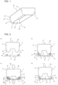
- Fig. 1 is a perspective view of a printing blanket 10 according to Embodiment 1 of the present invention.
- Figs. 2 are explanatory views for illustrating printing with the printing blanket 10 according to Embodiment 1 of the present invention.
- the printing blanket 10 illustrated in Fig. 1 is an elastic body having a recessed portion 12 in a center.
- a ridge line 11 surrounding the periphery of the recessed portion 12 is a site that is first brought into contact with a printing original plate 20 and a printing member 30 being a target for printing when the printing blanket 10 is pressed against the printing original plate 20 and the printing member 30.
- Figs. 1 is a perspective view of a printing blanket 10 according to Embodiment 1 of the present invention.
- Figs. 2 are explanatory views for illustrating printing with the printing blanket 10 according to Embodiment 1 of the present invention.
- the printing blanket 10 illustrated in Fig. 1 is an elastic body having a recessed portion 12 in a center.
- the printing blanket 10 is pressed against the printing original plate 20 having an ink 40 arranged on the printing original plate 20 and transfers the ink 40 to a printing surface 18 on a surface of the elastic body.
- the printing surface 18 is pressed against the printing member 30 in this state to transfer the ink 40 to the printing member 30.
- a base member 1 is mounted to, for example, a vertically-movable portion that is arranged in a printing device (not shown) and moves vertically.
- a mounting surface 15 of the base member 1 is mounted to the vertically-movable portion, and the base member 1 moves vertically in the printing device.
- the printing surface 18 is repeatedly pressed against the printing original plate 20 and the printing member 30. In this manner, printing on the printing member 30 is performed.
- the printing blanket 10 includes the base member 1 having a substantially rectangular shape when the printing blanket 10 is viewed in a direction from a side on which the printing original plate 20 and the printing member 30 are arranged on the printing device, that is, in a direction from a lower side in Figs. 2 .
- the base member 1 has the recessed portion 12 in the center.
- the recessed portion 12 is formed to be surrounded by a protruding portion 13 formed on a distal end side of the base member 1.
- the protruding portion 13 protrudes downward from a base portion 14 of the base member 1 on the mounting surface 15 side. That is, the sectional shape of the protruding portion 13 illustrated in Figs.
- the ridge line 11 which is an apex of the protruding portion 13, is formed to have a round shape.
- a curvature of the ridge line 11 is suitably changed corresponding to a curved surface 31 of the printing member 30.
- the ridge line 11 is not limited only to the round shape having a predetermined curvature, and may have a shape obtained by combining flat surfaces at the ridge line 11 or a shape obtained by combining a flat surface and a curved surface at the ridge line 11.
- Corner portions 16 of the base member 1 having a substantially rectangular shape when the base member 1 is viewed in the direction from the lower side are each formed to have a round shape.
- the roundness of each of the corner portions 16 is also suitably changed corresponding to the curved surface 31 of the printing member 30.
- Fig. 2(a) to Fig. 2(d) are views for illustrating printing using the printing blanket 10.
- Fig. 2(a) is a view for illustrating a state before the printing blanket 10 is pressed against the printing original plate 20.
- the ink 40 is arranged on the printing original plate 20.
- the ink 40 is arranged so that a plurality of ink drops are designed to form a predetermined printing image.
- the ink 40 is arranged on the printing original plate 20 by, for example, intaglio printing, relief printing, or inkjet printing.
- the printing blanket 10 is pressed against the printing original plate 20 from the ridge line 11 to be deformed, and a predetermined region mainly of the ridge line 11 is pressed against a surface of the printing original plate 20.
- the predetermined region is referred to as the printing surface 18.
- the ink 40 arranged on the printing original plate 20 adheres to be transferred to the printing surface 18 of the printing blanket 10.
- the base member 1 is easily deformed because the base member 1 is made of, for example, a silicon rubber containing a large amount of silicon oil.
- a solvent may be applied to the printing surface 18 to bring the printing surface 18 into a wet state. This treatment allows the ink 40 to be easily transferred to the printing surface 18.
- the printing surface 18 is pressed against the printing member 30. Consequently, the ink 40 transferred to the printing surface 18 is transferred from the printing surface 18 to the printing member 30, with the result that a printing image is transferred to the printing member 30.
- the printing blanket 10 is formed to be deformed easily. Consequently, the printing blanket 10 easily follows a surface to be printed having a curved surface shape and has satisfactory compatibility with such surface.
- Fig. 2(c) is a view for illustrating a cross section in a state in which the printing blanket 10 according to Embodiment 1 of the present invention is pressed against the printing member 30.
- the printing member 30 is, for example, a cover member having a curved surface to be adopted in a display portion of a touch panel in a smartphone or other devices.
- the cover member is made of, for example, a material such as glass and polycarbonate.
- the printing member 30 has a shape in which an edge of a rectangular flat plate in plan view is bent upward to form the curved surface 31 as illustrated in Fig. 2(c) .
- a surface of the printing member 30 on which printing is performed has a dish-like shape recessed at the center.
- the ink 40 not be arranged on the apex of the protruding portion 13, that is, on the ridge line 11.
- the ink 40 is arranged on the ridge line 11 and the printing blanket 10 is pressed against the printing original plate 20 or the printing member 30, air bubbles may be caught between the ink 40 and the printing surface 18, or between the ink 40 and the printing member 30. Consequently, the ink 40 is arranged on a surface on an outer side from the ridge line 11 on a surface of the base member 1.
- a pressing force 50 from the printing device is applied to the printing blanket 10 from the mounting surface 15 side.
- the pressing force 50 is transmitted to the printing member 30 through the base member 1.
- the base member 1 formed of an elastic body that is easily deformed is deformed by the pressing force 50 along the shape of the printing member 30.
- a portion of the base member 1 that faces a region on which printing is not performed corresponds to the recessed portion 12, and the recessed portion 12 is not brought into contact with the printing member 30.
- the pressing force 50 is applied to only a region including the printing surface 18 and brought into contact with the printing member 30, and is applied in a uniformly distributed manner as represented by the arrows 51 illustrated in Fig. 2(c) .
- the pressing force 50 can efficiently be applied to the printing surface 18, and hence as compared to the case where the recessed portion 12 is not arranged, the contact between the printing surface 18 and the curved surface 31 of the printing member 30 is satisfactory, resulting in good-quality printing.
- the printing blanket 10 has a substantially rectangular shape when the printing blanket 10 is viewed from the printing surface 18 side.
- the shape of the printing blanket 10 may be suitably changed corresponding to the shape of the printing member 30.
- the printing blanket 10 may be formed into, for example, a circular shape when the ridge line 11 is viewed from the printing surface 18 side.
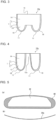
- Fig. 3 is a view for illustrating a cross section of a printing blanket 10a of a modification example of Embodiment 1 of the present invention.
- the printing blanket 10a is different from the printing blanket 10 in that the base member 1 includes two portions of an inner layer 2 and an outer coating layer 3. That is, the base member 1 is formed in such a manner that the outer coating layer 3 is bonded to a surface of the inner layer 2.
- the printing surface 18 lies on a surface of the outer coating layer 3.
- the outer coating layer 3 including the printing surface 18 is bonded to an outer surface of the inner layer 2 to ensure durability of the printing blanket 10 and reduce ooze of silicon oil from the inner layer 2.
- the outer coating layer 3 is made of a material having higher hardness than that of the inner layer 2, the outer coating layer 3 easily follows the deformation of the inner layer 2 because of its small thickness. That is, even when the printing surface 18 is pressed against the printing member 30 including the curved surface 31 illustrated in Figs. 2 , the printing surface 18 follows the curved surface 31. Further, the inner layer 2 and the outer coating layer 3 may be further formed of a plurality of layers.
- Fig. 4 is a view for illustrating a cross section of a printing blanket 10b of a modification example of Embodiment 1 of the present invention.
- the inner layer 2 may have a hole portion 12a instead of the recessed portion 12. That is, the inner layer 2 may be formed by surrounding the hole portion 12a with a three-dimensional shape including the ridge line 11.
- the printing blanket 10b includes the outer coating layer 3. However, the printing blanket 10b may be formed of only the inner layer 2.
- Figs. 5 are each a view for illustrating an example of a printing member 30a subjected to printing with the printing blanket 10 according to Embodiment 1 of the present invention.
- Fig. 5(a) is a front view of the printing member 30a.
- Fig. 5(b) is a bottom view of Fig. 5(a) , for illustrating the shape of the curved surface 31 of the printing member 30a on which printing is performed.
- the printing member 30a is, for example, an interior component of an automobile.
- the printing surface 18 of the printing blanket 10 is pressed against a portion of the printing member 30a that is illustrated with the hatched lines in Fig. 5(a) , and the ink 40 is printed on the portion.
- a center of the printing member 30a is a display portion 32.
- the display portion 32 does not have the ink 40 adhering to the display portion 32 and enables the surface of the printing member 30a to be visually recognized.
- the display portion 32 is generally transparent and enables the other side of the printing member 30a to be visually recognized.
- printing can be performed on a flat surface having a curved surface in an edge portion of the flat surface such as the printing member 30a.
Landscapes
- Printing Plates And Materials Therefor (AREA)
- Printing Methods (AREA)
Claims (5)
- Druckanordnung mit einer Druckvorlagenplatte (20) und einem Drucktuch (10, 10a), das eine Druckfläche (18) aufweist,
wobei die Druckvorlagenplatte (20) eine auf der Druckvorlagenplatte (20) angeordnete Druckfarbe (40) zum Übertragen von Druckfarbe (40) auf die Druckfläche (18) aufweist,
wobei das Drucktuch (10, 10a) umfasst:ein aus einem elastischen Material hergestelltes Basiselement (1), das eine dreidimensionale Form mit einem vertieften Abschnitt (12) oder einem Lochabschnitt (12a) in einer Mitte des Basiselements (1) aufweist, wobei der vertiefte Abschnitt (12) oder der Lochabschnitt (12a) so ausgebildet ist, dass er von einem vorstehenden Abschnitt (13) umgeben ist, der an einer entfernten Endseite des Basiselements (1) ausgebildet ist, wobei der vorstehende Abschnitt (13) von einem Basisabschnitt (14) des Basiselements (1) nach unten vorsteht,eine Wulstlinie (11), die den vertieften Abschnitt (12) oder den Lochabschnitt (12a) umgibt und einen Scheitelpunkt des vorstehenden Abschnitts (13) bildet, undwobei die Druckfläche (18) auf einer Oberfläche des Basiselements (1) auf einer Außenseite von der Wulstlinie (11) angeordnet ist, um die Druckfarbe (40) auf der Druckoberfläche (18) von der Druckvorlagenplatte (20) aufzunehmen, ohne dass Druckfarbe (40) auf der Wulstlinie (11) angeordnet ist,wobei das Basiselement (1) eine innere Schicht (2) und eine äußere Überzugsschicht (3) umfasst,wobei die äußere Überzugsschicht (3) die Form eines Blattes aufweist, mit einer Oberfläche der inneren Schicht (2) verbunden ist und aus einem Material mit einer höheren Härte als die innere Schicht (2) hergestellt ist. - Druckanordnung nach Anspruch 1, wobei die innere Schicht (2) eine Vielzahl von laminierten Schichten umfasst.
- Druckanordnung nach Anspruch 1 oder 2, wobei die äußere Überzugsschicht (3) eine Dicke von wenigstens 0,1 mm und höchstens 1,0 mm aufweist.
- Druckanordnung (10, 10a) nach einem der Ansprüche 1 bis 3, wobei die Innenschicht (2) aus einem silikonölhaltigen Silikonkautschuk besteht.
- Druckverfahren, umfassend:Pressen einer Druckfläche (18) gegen eine Druckvorlagenplatte (20), wobei eine Druckfarbe (40) auf der Druckvorlagenplatte (20) angeordnet ist, wodurch die Druckfarbe (40) von der Druckvorlagenplatte (20) auf die Druckfläche (18) übertragen wird, ohne dass Druckfarbe (40) auf der Wulstlinie (11) angeordnet ist, wobei die Druckfläche (18) auf einer Oberfläche eines aus einem elastischen Material hergestellten Basiselements (1) angeordnet ist, das eine dreidimensionale Form mit einem vertieften Abschnitt (12) oder einem Lochabschnitt (12a) in einer Mitte des Basiselements (1) und einer Wulstlinie (11) aufweist, die den vertieften Abschnitt (12) oder den Lochabschnitt (12a) umgibt, wobei sich die Druckfläche (18) des Basiselements (1) auf einer Außenseite von der Wulstlinie (11) befindet, undÜbertragen der Druckfarbe (40) von der Druckoberfläche (18) auf einen gekrümmten Oberflächenabschnitt (31) eines Druckelements (30, 30a) durch Pressen der Druckoberfläche (18) gegen den gekrümmten Oberflächenabschnitt (31),wobei das Druckelement (30, 30a) eine flache Oberfläche und eine gekrümmte Oberfläche in einem Randabschnitt der flachen Oberfläche aufweist, wobei die gekrümmte Oberfläche in dem Kantenabschnitt der gekrümmte Oberflächenabschnitt (31) ist und das Basiselement (1) eine innere Schicht (2) und eine äußere Überzugsschicht (3) umfasst,wobei die äußere Überzugsschicht (3) die Form eines Blattes aufweist, mit einer Oberfläche der inneren Schicht (2) verbunden ist und aus einem Material mit einer höheren Härte als die innere Schicht (2) hergestellt ist.
Applications Claiming Priority (1)
| Application Number | Priority Date | Filing Date | Title |
|---|---|---|---|
| PCT/JP2016/072472 WO2018025299A1 (ja) | 2016-08-01 | 2016-08-01 | 印刷用ブランケット及び印刷方法 |
Publications (3)
| Publication Number | Publication Date |
|---|---|
| EP3492272A1 EP3492272A1 (de) | 2019-06-05 |
| EP3492272A4 EP3492272A4 (de) | 2020-04-08 |
| EP3492272B1 true EP3492272B1 (de) | 2023-06-07 |
Family
ID=61072816
Family Applications (1)
| Application Number | Title | Priority Date | Filing Date |
|---|---|---|---|
| EP16901910.6A Active EP3492272B1 (de) | 2016-08-01 | 2016-08-01 | Drucktuch und druckverfahren |
Country Status (6)
| Country | Link |
|---|---|
| US (1) | US10894438B2 (de) |
| EP (1) | EP3492272B1 (de) |
| JP (1) | JP6832915B2 (de) |
| KR (2) | KR20190124342A (de) |
| CN (1) | CN107921809B (de) |
| WO (1) | WO2018025299A1 (de) |
Families Citing this family (3)
| Publication number | Priority date | Publication date | Assignee | Title |
|---|---|---|---|---|
| KR102669746B1 (ko) * | 2019-02-18 | 2024-05-28 | 삼성디스플레이 주식회사 | 커버 글라스 인쇄용 패드, 이를 이용한 커버 글라스의 제조방법 및 이에 의해 제조된 커버 글라스 |
| KR20210011524A (ko) * | 2019-07-22 | 2021-02-02 | 삼성디스플레이 주식회사 | 패드 인쇄 장치 |
| DE102020116763A1 (de) * | 2020-06-25 | 2021-12-30 | Phoenix Contact Gmbh & Co. Kg | Tampondruckvorrichtung |
Family Cites Families (16)
| Publication number | Priority date | Publication date | Assignee | Title |
|---|---|---|---|---|
| JPS59135160A (ja) * | 1983-01-21 | 1984-08-03 | Matsushita Electric Ind Co Ltd | 曲面印刷用転写装置 |
| JPS62132691A (ja) * | 1985-12-05 | 1987-06-15 | Toppan Printing Co Ltd | 印刷用パツド |
| US5066537A (en) * | 1990-10-04 | 1991-11-19 | W. R. Grace & Co.-Conn. | Printing blanket containing a high elongation fabric |
| JP2001317549A (ja) * | 2000-05-02 | 2001-11-16 | Daido Metal Co Ltd | 摺動部材の表層形成方法 |
| JP4947886B2 (ja) * | 2004-08-04 | 2012-06-06 | 株式会社秀峰 | 曲面への印刷方法およびそれによる印刷曲面体 |
| DE102007019398A1 (de) | 2007-04-23 | 2008-11-06 | Itw Morlock Gmbh | Tampondruckmaschine und Tampon dafür |
| US8151704B2 (en) * | 2008-02-21 | 2012-04-10 | Bridgestone Sports Co., Ltd | Method for printing on spherical object and pad to be used therefor |
| US7870823B1 (en) | 2008-08-11 | 2011-01-18 | Robert Cameron | Multilayer print pad |
| CN102378692B (zh) | 2009-04-01 | 2015-01-14 | 株式会社秀峰 | 印刷方法及被印刷体 |
| JP5441165B2 (ja) * | 2010-02-04 | 2014-03-12 | トリニティ工業株式会社 | ワーク表面装飾方法及びワーク表面装飾システム |
| JP5523150B2 (ja) * | 2010-03-05 | 2014-06-18 | 株式会社秀峰 | 印刷用パッドおよび印刷装置 |
| US9849709B2 (en) | 2010-03-05 | 2017-12-26 | Shuhou Co., Ltd. | Printing blanket, printing device, and method of manufacturing printing blanket |
| US9340058B2 (en) | 2010-03-19 | 2016-05-17 | Lg Chem, Ltd. | Blanket for offset printing and manufacturing method therefor |
| JP2011224892A (ja) | 2010-04-21 | 2011-11-10 | Shuho:Kk | 印刷用ブランケット |
| JP2015068909A (ja) | 2013-09-27 | 2015-04-13 | Hoya株式会社 | 電子機器用カバーガラスの製造方法 |
| JP2016189549A (ja) | 2015-03-30 | 2016-11-04 | Necディスプレイソリューションズ株式会社 | 色むら評価装置、方法及びプログラム |
-
2016
- 2016-08-01 JP JP2018505044A patent/JP6832915B2/ja active Active
- 2016-08-01 US US15/735,435 patent/US10894438B2/en active Active
- 2016-08-01 KR KR1020197031719A patent/KR20190124342A/ko not_active Ceased
- 2016-08-01 EP EP16901910.6A patent/EP3492272B1/de active Active
- 2016-08-01 CN CN201680035350.9A patent/CN107921809B/zh active Active
- 2016-08-01 WO PCT/JP2016/072472 patent/WO2018025299A1/ja not_active Ceased
- 2016-08-01 KR KR1020177034971A patent/KR20180043204A/ko not_active Ceased
Also Published As
| Publication number | Publication date |
|---|---|
| US20200039276A1 (en) | 2020-02-06 |
| US10894438B2 (en) | 2021-01-19 |
| JP6832915B2 (ja) | 2021-02-24 |
| CN107921809A (zh) | 2018-04-17 |
| EP3492272A1 (de) | 2019-06-05 |
| KR20190124342A (ko) | 2019-11-04 |
| KR20180043204A (ko) | 2018-04-27 |
| JPWO2018025299A1 (ja) | 2019-05-23 |
| CN107921809B (zh) | 2020-03-10 |
| WO2018025299A1 (ja) | 2018-02-08 |
| EP3492272A4 (de) | 2020-04-08 |
Similar Documents
| Publication | Publication Date | Title |
|---|---|---|
| KR101528967B1 (ko) | 인쇄용 블랭킷, 인쇄 장치 및 인쇄용 블랭킷의 제조 방법 | |
| US10894438B2 (en) | Printing blanket and printing method | |
| KR20150132653A (ko) | 인쇄층이 형성된 터치 스크린 패널용 커버 윈도우 및 터치 스크린 패널용 커버 윈도우에 인쇄층을 형성하는 방법 | |
| CN105324742A (zh) | 触摸屏显示单元及其制造方法 | |
| EP3035380B1 (de) | Vorrichtung zur trennung eines flexiblen substrats von einem glassubstrat und herstellungsvorrichtung dafür | |
| US9874788B2 (en) | Display panel, method of manufacturing the same, and display device | |
| KR20170064850A (ko) | 휴대단말기용 전면 보호 필름 및 그 제조방법 | |
| CN104309344B (zh) | 网版印刷方法 | |
| JP5912985B2 (ja) | タッチパネル及びその製造方法 | |
| CN104007877A (zh) | 触控显示设备用的高黏着力贴合结构 | |
| JP5398627B2 (ja) | 印刷用ブランケットの製造方法 | |
| CN102248756A (zh) | 印刷系统,其包含的印刷网板、印刷模板及其印刷方法 | |
| US20080002118A1 (en) | Flexible display substrate module and method of manufacturing flexible display device | |
| KR20170033207A (ko) | 곡면부를 갖는 강화 유리, 강화 유리 필름 및 그 제조방법 | |
| TW201726437A (zh) | 印刷用膠毯的製造方法 | |
| US20060210720A1 (en) | Patterning method of liquid crystal display device | |
| KR102061310B1 (ko) | 곡면 디스플레이 장치용 광학필름 및 그 제조방법 | |
| KR102065482B1 (ko) | 광학필름의 그 제조방법 | |
| TWI733149B (zh) | 印刷用膠毯及印刷用膠毯的製造方法 | |
| KR20120135726A (ko) | 점착척 및 그 제조방법 | |
| CN100402310C (zh) | 用于印刷辊的橡皮布 | |
| CN110867137A (zh) | 显示面板的制备方法及显示面板 | |
| JP7329240B2 (ja) | 被着フィルムの成形方法 | |
| KR101467444B1 (ko) | Uv 패턴을 포함하는 카메라 글라스의 제조방법 | |
| JPH03198029A (ja) | 液晶表示素子の製造装置 |
Legal Events
| Date | Code | Title | Description |
|---|---|---|---|
| STAA | Information on the status of an ep patent application or granted ep patent |
Free format text: STATUS: UNKNOWN |
|
| STAA | Information on the status of an ep patent application or granted ep patent |
Free format text: STATUS: THE INTERNATIONAL PUBLICATION HAS BEEN MADE |
|
| PUAI | Public reference made under article 153(3) epc to a published international application that has entered the european phase |
Free format text: ORIGINAL CODE: 0009012 |
|
| STAA | Information on the status of an ep patent application or granted ep patent |
Free format text: STATUS: REQUEST FOR EXAMINATION WAS MADE |
|
| 17P | Request for examination filed |
Effective date: 20171123 |
|
| AK | Designated contracting states |
Kind code of ref document: A1 Designated state(s): AL AT BE BG CH CY CZ DE DK EE ES FI FR GB GR HR HU IE IS IT LI LT LU LV MC MK MT NL NO PL PT RO RS SE SI SK SM TR |
|
| AX | Request for extension of the european patent |
Extension state: BA ME |
|
| DAV | Request for validation of the european patent (deleted) | ||
| DAX | Request for extension of the european patent (deleted) | ||
| REG | Reference to a national code |
Ref country code: DE Ref legal event code: R079 Free format text: PREVIOUS MAIN CLASS: B41N0010040000 Ipc: B41F0017000000 Ref country code: DE Ref legal event code: R079 Ref document number: 602016080229 Country of ref document: DE Free format text: PREVIOUS MAIN CLASS: B41N0010040000 Ipc: B41F0017000000 |
|
| A4 | Supplementary search report drawn up and despatched |
Effective date: 20200310 |
|
| RIC1 | Information provided on ipc code assigned before grant |
Ipc: B41M 1/40 20060101ALN20200304BHEP Ipc: B41M 1/34 20060101ALN20200304BHEP Ipc: B41M 1/26 20060101ALN20200304BHEP Ipc: B41F 17/00 20060101AFI20200304BHEP Ipc: B41N 10/04 20060101ALN20200304BHEP |
|
| STAA | Information on the status of an ep patent application or granted ep patent |
Free format text: STATUS: EXAMINATION IS IN PROGRESS |
|
| 17Q | First examination report despatched |
Effective date: 20220223 |
|
| GRAP | Despatch of communication of intention to grant a patent |
Free format text: ORIGINAL CODE: EPIDOSNIGR1 |
|
| STAA | Information on the status of an ep patent application or granted ep patent |
Free format text: STATUS: GRANT OF PATENT IS INTENDED |
|
| INTG | Intention to grant announced |
Effective date: 20230303 |
|
| GRAS | Grant fee paid |
Free format text: ORIGINAL CODE: EPIDOSNIGR3 |
|
| GRAA | (expected) grant |
Free format text: ORIGINAL CODE: 0009210 |
|
| STAA | Information on the status of an ep patent application or granted ep patent |
Free format text: STATUS: THE PATENT HAS BEEN GRANTED |
|
| AK | Designated contracting states |
Kind code of ref document: B1 Designated state(s): AL AT BE BG CH CY CZ DE DK EE ES FI FR GB GR HR HU IE IS IT LI LT LU LV MC MK MT NL NO PL PT RO RS SE SI SK SM TR |
|
| REG | Reference to a national code |
Ref country code: GB Ref legal event code: FG4D |
|
| REG | Reference to a national code |
Ref country code: CH Ref legal event code: EP Ref country code: AT Ref legal event code: REF Ref document number: 1573868 Country of ref document: AT Kind code of ref document: T Effective date: 20230615 |
|
| REG | Reference to a national code |
Ref country code: DE Ref legal event code: R096 Ref document number: 602016080229 Country of ref document: DE |
|
| P01 | Opt-out of the competence of the unified patent court (upc) registered |
Effective date: 20230522 |
|
| P02 | Opt-out of the competence of the unified patent court (upc) changed |
Effective date: 20230724 |
|
| REG | Reference to a national code |
Ref country code: LT Ref legal event code: MG9D |
|
| REG | Reference to a national code |
Ref country code: NL Ref legal event code: MP Effective date: 20230607 |
|
| PG25 | Lapsed in a contracting state [announced via postgrant information from national office to epo] |
Ref country code: SE Free format text: LAPSE BECAUSE OF FAILURE TO SUBMIT A TRANSLATION OF THE DESCRIPTION OR TO PAY THE FEE WITHIN THE PRESCRIBED TIME-LIMIT Effective date: 20230607 Ref country code: NO Free format text: LAPSE BECAUSE OF FAILURE TO SUBMIT A TRANSLATION OF THE DESCRIPTION OR TO PAY THE FEE WITHIN THE PRESCRIBED TIME-LIMIT Effective date: 20230907 Ref country code: ES Free format text: LAPSE BECAUSE OF FAILURE TO SUBMIT A TRANSLATION OF THE DESCRIPTION OR TO PAY THE FEE WITHIN THE PRESCRIBED TIME-LIMIT Effective date: 20230607 |
|
| REG | Reference to a national code |
Ref country code: AT Ref legal event code: MK05 Ref document number: 1573868 Country of ref document: AT Kind code of ref document: T Effective date: 20230607 |
|
| PG25 | Lapsed in a contracting state [announced via postgrant information from national office to epo] |
Ref country code: RS Free format text: LAPSE BECAUSE OF FAILURE TO SUBMIT A TRANSLATION OF THE DESCRIPTION OR TO PAY THE FEE WITHIN THE PRESCRIBED TIME-LIMIT Effective date: 20230607 Ref country code: NL Free format text: LAPSE BECAUSE OF FAILURE TO SUBMIT A TRANSLATION OF THE DESCRIPTION OR TO PAY THE FEE WITHIN THE PRESCRIBED TIME-LIMIT Effective date: 20230607 Ref country code: LV Free format text: LAPSE BECAUSE OF FAILURE TO SUBMIT A TRANSLATION OF THE DESCRIPTION OR TO PAY THE FEE WITHIN THE PRESCRIBED TIME-LIMIT Effective date: 20230607 Ref country code: LT Free format text: LAPSE BECAUSE OF FAILURE TO SUBMIT A TRANSLATION OF THE DESCRIPTION OR TO PAY THE FEE WITHIN THE PRESCRIBED TIME-LIMIT Effective date: 20230607 Ref country code: HR Free format text: LAPSE BECAUSE OF FAILURE TO SUBMIT A TRANSLATION OF THE DESCRIPTION OR TO PAY THE FEE WITHIN THE PRESCRIBED TIME-LIMIT Effective date: 20230607 Ref country code: GR Free format text: LAPSE BECAUSE OF FAILURE TO SUBMIT A TRANSLATION OF THE DESCRIPTION OR TO PAY THE FEE WITHIN THE PRESCRIBED TIME-LIMIT Effective date: 20230908 |
|
| PG25 | Lapsed in a contracting state [announced via postgrant information from national office to epo] |
Ref country code: FI Free format text: LAPSE BECAUSE OF FAILURE TO SUBMIT A TRANSLATION OF THE DESCRIPTION OR TO PAY THE FEE WITHIN THE PRESCRIBED TIME-LIMIT Effective date: 20230607 |
|
| PG25 | Lapsed in a contracting state [announced via postgrant information from national office to epo] |
Ref country code: SK Free format text: LAPSE BECAUSE OF FAILURE TO SUBMIT A TRANSLATION OF THE DESCRIPTION OR TO PAY THE FEE WITHIN THE PRESCRIBED TIME-LIMIT Effective date: 20230607 |
|
| PG25 | Lapsed in a contracting state [announced via postgrant information from national office to epo] |
Ref country code: IS Free format text: LAPSE BECAUSE OF FAILURE TO SUBMIT A TRANSLATION OF THE DESCRIPTION OR TO PAY THE FEE WITHIN THE PRESCRIBED TIME-LIMIT Effective date: 20231007 |
|
| PG25 | Lapsed in a contracting state [announced via postgrant information from national office to epo] |
Ref country code: SM Free format text: LAPSE BECAUSE OF FAILURE TO SUBMIT A TRANSLATION OF THE DESCRIPTION OR TO PAY THE FEE WITHIN THE PRESCRIBED TIME-LIMIT Effective date: 20230607 Ref country code: SK Free format text: LAPSE BECAUSE OF FAILURE TO SUBMIT A TRANSLATION OF THE DESCRIPTION OR TO PAY THE FEE WITHIN THE PRESCRIBED TIME-LIMIT Effective date: 20230607 Ref country code: RO Free format text: LAPSE BECAUSE OF FAILURE TO SUBMIT A TRANSLATION OF THE DESCRIPTION OR TO PAY THE FEE WITHIN THE PRESCRIBED TIME-LIMIT Effective date: 20230607 Ref country code: PT Free format text: LAPSE BECAUSE OF FAILURE TO SUBMIT A TRANSLATION OF THE DESCRIPTION OR TO PAY THE FEE WITHIN THE PRESCRIBED TIME-LIMIT Effective date: 20231009 Ref country code: IS Free format text: LAPSE BECAUSE OF FAILURE TO SUBMIT A TRANSLATION OF THE DESCRIPTION OR TO PAY THE FEE WITHIN THE PRESCRIBED TIME-LIMIT Effective date: 20231007 Ref country code: EE Free format text: LAPSE BECAUSE OF FAILURE TO SUBMIT A TRANSLATION OF THE DESCRIPTION OR TO PAY THE FEE WITHIN THE PRESCRIBED TIME-LIMIT Effective date: 20230607 Ref country code: CZ Free format text: LAPSE BECAUSE OF FAILURE TO SUBMIT A TRANSLATION OF THE DESCRIPTION OR TO PAY THE FEE WITHIN THE PRESCRIBED TIME-LIMIT Effective date: 20230607 Ref country code: AT Free format text: LAPSE BECAUSE OF FAILURE TO SUBMIT A TRANSLATION OF THE DESCRIPTION OR TO PAY THE FEE WITHIN THE PRESCRIBED TIME-LIMIT Effective date: 20230607 |
|
| PG25 | Lapsed in a contracting state [announced via postgrant information from national office to epo] |
Ref country code: PL Free format text: LAPSE BECAUSE OF FAILURE TO SUBMIT A TRANSLATION OF THE DESCRIPTION OR TO PAY THE FEE WITHIN THE PRESCRIBED TIME-LIMIT Effective date: 20230607 |
|
| REG | Reference to a national code |
Ref country code: DE Ref legal event code: R097 Ref document number: 602016080229 Country of ref document: DE |
|
| PG25 | Lapsed in a contracting state [announced via postgrant information from national office to epo] |
Ref country code: MC Free format text: LAPSE BECAUSE OF FAILURE TO SUBMIT A TRANSLATION OF THE DESCRIPTION OR TO PAY THE FEE WITHIN THE PRESCRIBED TIME-LIMIT Effective date: 20230607 |
|
| REG | Reference to a national code |
Ref country code: CH Ref legal event code: PL |
|
| PG25 | Lapsed in a contracting state [announced via postgrant information from national office to epo] |
Ref country code: MC Free format text: LAPSE BECAUSE OF FAILURE TO SUBMIT A TRANSLATION OF THE DESCRIPTION OR TO PAY THE FEE WITHIN THE PRESCRIBED TIME-LIMIT Effective date: 20230607 |
|
| PLBE | No opposition filed within time limit |
Free format text: ORIGINAL CODE: 0009261 |
|
| STAA | Information on the status of an ep patent application or granted ep patent |
Free format text: STATUS: NO OPPOSITION FILED WITHIN TIME LIMIT |
|
| PG25 | Lapsed in a contracting state [announced via postgrant information from national office to epo] |
Ref country code: LU Free format text: LAPSE BECAUSE OF NON-PAYMENT OF DUE FEES Effective date: 20230801 |
|
| PG25 | Lapsed in a contracting state [announced via postgrant information from national office to epo] |
Ref country code: LU Free format text: LAPSE BECAUSE OF NON-PAYMENT OF DUE FEES Effective date: 20230801 Ref country code: DK Free format text: LAPSE BECAUSE OF FAILURE TO SUBMIT A TRANSLATION OF THE DESCRIPTION OR TO PAY THE FEE WITHIN THE PRESCRIBED TIME-LIMIT Effective date: 20230607 Ref country code: CH Free format text: LAPSE BECAUSE OF NON-PAYMENT OF DUE FEES Effective date: 20230831 |
|
| PG25 | Lapsed in a contracting state [announced via postgrant information from national office to epo] |
Ref country code: SI Free format text: LAPSE BECAUSE OF FAILURE TO SUBMIT A TRANSLATION OF THE DESCRIPTION OR TO PAY THE FEE WITHIN THE PRESCRIBED TIME-LIMIT Effective date: 20230607 |
|
| REG | Reference to a national code |
Ref country code: BE Ref legal event code: MM Effective date: 20230831 |
|
| 26N | No opposition filed |
Effective date: 20240308 |
|
| REG | Reference to a national code |
Ref country code: IE Ref legal event code: MM4A |
|
| PG25 | Lapsed in a contracting state [announced via postgrant information from national office to epo] |
Ref country code: SI Free format text: LAPSE BECAUSE OF FAILURE TO SUBMIT A TRANSLATION OF THE DESCRIPTION OR TO PAY THE FEE WITHIN THE PRESCRIBED TIME-LIMIT Effective date: 20230607 Ref country code: IT Free format text: LAPSE BECAUSE OF FAILURE TO SUBMIT A TRANSLATION OF THE DESCRIPTION OR TO PAY THE FEE WITHIN THE PRESCRIBED TIME-LIMIT Effective date: 20230607 |
|
| PG25 | Lapsed in a contracting state [announced via postgrant information from national office to epo] |
Ref country code: IE Free format text: LAPSE BECAUSE OF NON-PAYMENT OF DUE FEES Effective date: 20230801 |
|
| PG25 | Lapsed in a contracting state [announced via postgrant information from national office to epo] |
Ref country code: IE Free format text: LAPSE BECAUSE OF NON-PAYMENT OF DUE FEES Effective date: 20230801 |
|
| PG25 | Lapsed in a contracting state [announced via postgrant information from national office to epo] |
Ref country code: BE Free format text: LAPSE BECAUSE OF NON-PAYMENT OF DUE FEES Effective date: 20230831 |
|
| PG25 | Lapsed in a contracting state [announced via postgrant information from national office to epo] |
Ref country code: BG Free format text: LAPSE BECAUSE OF FAILURE TO SUBMIT A TRANSLATION OF THE DESCRIPTION OR TO PAY THE FEE WITHIN THE PRESCRIBED TIME-LIMIT Effective date: 20230607 |
|
| PG25 | Lapsed in a contracting state [announced via postgrant information from national office to epo] |
Ref country code: BG Free format text: LAPSE BECAUSE OF FAILURE TO SUBMIT A TRANSLATION OF THE DESCRIPTION OR TO PAY THE FEE WITHIN THE PRESCRIBED TIME-LIMIT Effective date: 20230607 |
|
| PG25 | Lapsed in a contracting state [announced via postgrant information from national office to epo] |
Ref country code: CY Free format text: LAPSE BECAUSE OF FAILURE TO SUBMIT A TRANSLATION OF THE DESCRIPTION OR TO PAY THE FEE WITHIN THE PRESCRIBED TIME-LIMIT; INVALID AB INITIO Effective date: 20160801 |
|
| PG25 | Lapsed in a contracting state [announced via postgrant information from national office to epo] |
Ref country code: HU Free format text: LAPSE BECAUSE OF FAILURE TO SUBMIT A TRANSLATION OF THE DESCRIPTION OR TO PAY THE FEE WITHIN THE PRESCRIBED TIME-LIMIT; INVALID AB INITIO Effective date: 20160801 |
|
| PGFP | Annual fee paid to national office [announced via postgrant information from national office to epo] |
Ref country code: DE Payment date: 20250702 Year of fee payment: 10 |
|
| PGFP | Annual fee paid to national office [announced via postgrant information from national office to epo] |
Ref country code: GB Payment date: 20250703 Year of fee payment: 10 |
|
| PGFP | Annual fee paid to national office [announced via postgrant information from national office to epo] |
Ref country code: FR Payment date: 20250703 Year of fee payment: 10 |
|
| PG25 | Lapsed in a contracting state [announced via postgrant information from national office to epo] |
Ref country code: TR Free format text: LAPSE BECAUSE OF FAILURE TO SUBMIT A TRANSLATION OF THE DESCRIPTION OR TO PAY THE FEE WITHIN THE PRESCRIBED TIME-LIMIT Effective date: 20230607 |