EP3491345B2 - Pumpkopf und dosiervorrichtung - Google Patents
Pumpkopf und dosiervorrichtung Download PDFInfo
- Publication number
- EP3491345B2 EP3491345B2 EP17729067.3A EP17729067A EP3491345B2 EP 3491345 B2 EP3491345 B2 EP 3491345B2 EP 17729067 A EP17729067 A EP 17729067A EP 3491345 B2 EP3491345 B2 EP 3491345B2
- Authority
- EP
- European Patent Office
- Prior art keywords
- component
- head
- pump head
- pump
- valve
- Prior art date
- Legal status (The legal status is an assumption and is not a legal conclusion. Google has not performed a legal analysis and makes no representation as to the accuracy of the status listed.)
- Active
Links
Images

Classifications
-
- G—PHYSICS
- G01—MEASURING; TESTING
- G01F—MEASURING VOLUME, VOLUME FLOW, MASS FLOW OR LIQUID LEVEL; METERING BY VOLUME
- G01F15/00—Details of, or accessories for, apparatus of groups G01F1/00 - G01F13/00 insofar as such details or appliances are not adapted to particular types of such apparatus
- G01F15/005—Valves
-
- B—PERFORMING OPERATIONS; TRANSPORTING
- B05—SPRAYING OR ATOMISING IN GENERAL; APPLYING FLUENT MATERIALS TO SURFACES, IN GENERAL
- B05B—SPRAYING APPARATUS; ATOMISING APPARATUS; NOZZLES
- B05B11/00—Single-unit hand-held apparatus in which flow of contents is produced by the muscular force of the operator at the moment of use
- B05B11/0005—Components or details
- B05B11/0062—Outlet valves actuated by the pressure of the fluid to be sprayed
- B05B11/0064—Lift valves
- B05B11/0067—Lift valves having a valve seat located downstream the valve element
-
- B—PERFORMING OPERATIONS; TRANSPORTING
- B05—SPRAYING OR ATOMISING IN GENERAL; APPLYING FLUENT MATERIALS TO SURFACES, IN GENERAL
- B05B—SPRAYING APPARATUS; ATOMISING APPARATUS; NOZZLES
- B05B11/00—Single-unit hand-held apparatus in which flow of contents is produced by the muscular force of the operator at the moment of use
- B05B11/0005—Components or details
- B05B11/0062—Outlet valves actuated by the pressure of the fluid to be sprayed
- B05B11/007—Outlet valves actuated by the pressure of the fluid to be sprayed being opened by deformation of a sealing element made of resiliently deformable material, e.g. flaps, skirts, duck-bill valves
-
- B—PERFORMING OPERATIONS; TRANSPORTING
- B05—SPRAYING OR ATOMISING IN GENERAL; APPLYING FLUENT MATERIALS TO SURFACES, IN GENERAL
- B05B—SPRAYING APPARATUS; ATOMISING APPARATUS; NOZZLES
- B05B11/00—Single-unit hand-held apparatus in which flow of contents is produced by the muscular force of the operator at the moment of use
- B05B11/01—Single-unit hand-held apparatus in which flow of contents is produced by the muscular force of the operator at the moment of use characterised by the means producing the flow
- B05B11/04—Deformable containers producing the flow, e.g. squeeze bottles
- B05B11/047—Deformable containers producing the flow, e.g. squeeze bottles characterised by the outlet or venting means
-
- B—PERFORMING OPERATIONS; TRANSPORTING
- B05—SPRAYING OR ATOMISING IN GENERAL; APPLYING FLUENT MATERIALS TO SURFACES, IN GENERAL
- B05B—SPRAYING APPARATUS; ATOMISING APPARATUS; NOZZLES
- B05B11/00—Single-unit hand-held apparatus in which flow of contents is produced by the muscular force of the operator at the moment of use
- B05B11/01—Single-unit hand-held apparatus in which flow of contents is produced by the muscular force of the operator at the moment of use characterised by the means producing the flow
- B05B11/04—Deformable containers producing the flow, e.g. squeeze bottles
- B05B11/048—Deformable containers producing the flow, e.g. squeeze bottles characterised by the container, e.g. this latter being surrounded by an enclosure, or the means for deforming it
-
- B—PERFORMING OPERATIONS; TRANSPORTING
- B65—CONVEYING; PACKING; STORING; HANDLING THIN OR FILAMENTARY MATERIAL
- B65D—CONTAINERS FOR STORAGE OR TRANSPORT OF ARTICLES OR MATERIALS, e.g. BAGS, BARRELS, BOTTLES, BOXES, CANS, CARTONS, CRATES, DRUMS, JARS, TANKS, HOPPERS, FORWARDING CONTAINERS; ACCESSORIES, CLOSURES, OR FITTINGS THEREFOR; PACKAGING ELEMENTS; PACKAGES
- B65D47/00—Closures with filling and discharging, or with discharging, devices
- B65D47/04—Closures with discharging devices other than pumps
- B65D47/20—Closures with discharging devices other than pumps comprising hand-operated members for controlling discharge
- B65D47/2018—Closures with discharging devices other than pumps comprising hand-operated members for controlling discharge comprising a valve or like element which is opened or closed by deformation of the container or closure
- B65D47/2056—Closures with discharging devices other than pumps comprising hand-operated members for controlling discharge comprising a valve or like element which is opened or closed by deformation of the container or closure lift valve type
- B65D47/2062—Closures with discharging devices other than pumps comprising hand-operated members for controlling discharge comprising a valve or like element which is opened or closed by deformation of the container or closure lift valve type in which the deformation raises or lowers the valve stem
- B65D47/2068—Closures with discharging devices other than pumps comprising hand-operated members for controlling discharge comprising a valve or like element which is opened or closed by deformation of the container or closure lift valve type in which the deformation raises or lowers the valve stem in which the stem is lowered by the pressure of the contents and thereby opening the valve
-
- B—PERFORMING OPERATIONS; TRANSPORTING
- B67—OPENING, CLOSING OR CLEANING BOTTLES, JARS OR SIMILAR CONTAINERS; LIQUID HANDLING
- B67D—DISPENSING, DELIVERING OR TRANSFERRING LIQUIDS, NOT OTHERWISE PROVIDED FOR
- B67D1/00—Apparatus or devices for dispensing beverages on draught
- B67D1/0015—Apparatus or devices for dispensing beverages on draught the beverage being prepared by mixing at least two liquid components
- B67D1/0021—Apparatus or devices for dispensing beverages on draught the beverage being prepared by mixing at least two liquid components the components being mixed at the time of dispensing, i.e. post-mix dispensers
- B67D1/0022—Apparatus or devices for dispensing beverages on draught the beverage being prepared by mixing at least two liquid components the components being mixed at the time of dispensing, i.e. post-mix dispensers the apparatus comprising means for automatically controlling the amount to be dispensed
- B67D1/0034—Apparatus or devices for dispensing beverages on draught the beverage being prepared by mixing at least two liquid components the components being mixed at the time of dispensing, i.e. post-mix dispensers the apparatus comprising means for automatically controlling the amount to be dispensed for controlling the amount of each component
- B67D1/0035—Apparatus or devices for dispensing beverages on draught the beverage being prepared by mixing at least two liquid components the components being mixed at the time of dispensing, i.e. post-mix dispensers the apparatus comprising means for automatically controlling the amount to be dispensed for controlling the amount of each component the controls being based on the same metering technics
- B67D1/0037—Apparatus or devices for dispensing beverages on draught the beverage being prepared by mixing at least two liquid components the components being mixed at the time of dispensing, i.e. post-mix dispensers the apparatus comprising means for automatically controlling the amount to be dispensed for controlling the amount of each component the controls being based on the same metering technics based on volumetric dosing
-
- B—PERFORMING OPERATIONS; TRANSPORTING
- B67—OPENING, CLOSING OR CLEANING BOTTLES, JARS OR SIMILAR CONTAINERS; LIQUID HANDLING
- B67D—DISPENSING, DELIVERING OR TRANSFERRING LIQUIDS, NOT OTHERWISE PROVIDED FOR
- B67D1/00—Apparatus or devices for dispensing beverages on draught
- B67D1/0042—Details of specific parts of the dispensers
- B67D1/0043—Mixing devices for liquids
- B67D1/0044—Mixing devices for liquids for mixing inside the dispensing nozzle
-
- B—PERFORMING OPERATIONS; TRANSPORTING
- B67—OPENING, CLOSING OR CLEANING BOTTLES, JARS OR SIMILAR CONTAINERS; LIQUID HANDLING
- B67D—DISPENSING, DELIVERING OR TRANSFERRING LIQUIDS, NOT OTHERWISE PROVIDED FOR
- B67D1/00—Apparatus or devices for dispensing beverages on draught
- B67D1/0042—Details of specific parts of the dispensers
- B67D1/0078—Ingredient cartridges
- B67D1/0079—Ingredient cartridges having their own dispensing means
-
- B—PERFORMING OPERATIONS; TRANSPORTING
- B67—OPENING, CLOSING OR CLEANING BOTTLES, JARS OR SIMILAR CONTAINERS; LIQUID HANDLING
- B67D—DISPENSING, DELIVERING OR TRANSFERRING LIQUIDS, NOT OTHERWISE PROVIDED FOR
- B67D1/00—Apparatus or devices for dispensing beverages on draught
- B67D1/08—Details
- B67D1/10—Pump mechanism
- B67D1/101—Pump mechanism of the piston-cylinder type
- B67D1/105—Pump mechanism of the piston-cylinder type for two or more components
-
- B—PERFORMING OPERATIONS; TRANSPORTING
- B67—OPENING, CLOSING OR CLEANING BOTTLES, JARS OR SIMILAR CONTAINERS; LIQUID HANDLING
- B67D—DISPENSING, DELIVERING OR TRANSFERRING LIQUIDS, NOT OTHERWISE PROVIDED FOR
- B67D1/00—Apparatus or devices for dispensing beverages on draught
- B67D1/08—Details
- B67D1/12—Flow or pressure control devices or systems, e.g. valves, gas pressure control, level control in storage containers
- B67D1/1202—Flow control, e.g. for controlling total amount or mixture ratio of liquids to be dispensed
- B67D1/1204—Flow control, e.g. for controlling total amount or mixture ratio of liquids to be dispensed for ratio control purposes
- B67D1/1231—Metering pumps
-
- F—MECHANICAL ENGINEERING; LIGHTING; HEATING; WEAPONS; BLASTING
- F16—ENGINEERING ELEMENTS AND UNITS; GENERAL MEASURES FOR PRODUCING AND MAINTAINING EFFECTIVE FUNCTIONING OF MACHINES OR INSTALLATIONS; THERMAL INSULATION IN GENERAL
- F16K—VALVES; TAPS; COCKS; ACTUATING-FLOATS; DEVICES FOR VENTING OR AERATING
- F16K15/00—Check valves
- F16K15/14—Check valves with flexible valve members
- F16K15/144—Check valves with flexible valve members the closure elements being fixed along all or a part of their periphery
- F16K15/145—Check valves with flexible valve members the closure elements being fixed along all or a part of their periphery the closure elements being shaped as a solids of revolution, e.g. cylindrical or conical
-
- G—PHYSICS
- G01—MEASURING; TESTING
- G01F—MEASURING VOLUME, VOLUME FLOW, MASS FLOW OR LIQUID LEVEL; METERING BY VOLUME
- G01F11/00—Apparatus requiring external operation adapted at each repeated and identical operation to measure and separate a predetermined volume of fluid or fluent solid material from a supply or container, without regard to weight, and to deliver it
- G01F11/02—Apparatus requiring external operation adapted at each repeated and identical operation to measure and separate a predetermined volume of fluid or fluent solid material from a supply or container, without regard to weight, and to deliver it with measuring chambers which expand or contract during measurement
- G01F11/021—Apparatus requiring external operation adapted at each repeated and identical operation to measure and separate a predetermined volume of fluid or fluent solid material from a supply or container, without regard to weight, and to deliver it with measuring chambers which expand or contract during measurement of the piston type
-
- G—PHYSICS
- G01—MEASURING; TESTING
- G01F—MEASURING VOLUME, VOLUME FLOW, MASS FLOW OR LIQUID LEVEL; METERING BY VOLUME
- G01F11/00—Apparatus requiring external operation adapted at each repeated and identical operation to measure and separate a predetermined volume of fluid or fluent solid material from a supply or container, without regard to weight, and to deliver it
- G01F11/02—Apparatus requiring external operation adapted at each repeated and identical operation to measure and separate a predetermined volume of fluid or fluent solid material from a supply or container, without regard to weight, and to deliver it with measuring chambers which expand or contract during measurement
- G01F11/04—Apparatus requiring external operation adapted at each repeated and identical operation to measure and separate a predetermined volume of fluid or fluent solid material from a supply or container, without regard to weight, and to deliver it with measuring chambers which expand or contract during measurement of the free-piston type
-
- G—PHYSICS
- G01—MEASURING; TESTING
- G01F—MEASURING VOLUME, VOLUME FLOW, MASS FLOW OR LIQUID LEVEL; METERING BY VOLUME
- G01F11/00—Apparatus requiring external operation adapted at each repeated and identical operation to measure and separate a predetermined volume of fluid or fluent solid material from a supply or container, without regard to weight, and to deliver it
- G01F11/02—Apparatus requiring external operation adapted at each repeated and identical operation to measure and separate a predetermined volume of fluid or fluent solid material from a supply or container, without regard to weight, and to deliver it with measuring chambers which expand or contract during measurement
- G01F11/08—Apparatus requiring external operation adapted at each repeated and identical operation to measure and separate a predetermined volume of fluid or fluent solid material from a supply or container, without regard to weight, and to deliver it with measuring chambers which expand or contract during measurement of the diaphragm or bellows type
- G01F11/082—Apparatus requiring external operation adapted at each repeated and identical operation to measure and separate a predetermined volume of fluid or fluent solid material from a supply or container, without regard to weight, and to deliver it with measuring chambers which expand or contract during measurement of the diaphragm or bellows type of the squeeze container type
-
- B—PERFORMING OPERATIONS; TRANSPORTING
- B05—SPRAYING OR ATOMISING IN GENERAL; APPLYING FLUENT MATERIALS TO SURFACES, IN GENERAL
- B05B—SPRAYING APPARATUS; ATOMISING APPARATUS; NOZZLES
- B05B11/00—Single-unit hand-held apparatus in which flow of contents is produced by the muscular force of the operator at the moment of use
- B05B11/01—Single-unit hand-held apparatus in which flow of contents is produced by the muscular force of the operator at the moment of use characterised by the means producing the flow
- B05B11/10—Pump arrangements for transferring the contents from the container to a pump chamber by a sucking effect and forcing the contents out through the dispensing nozzle
- B05B11/1001—Piston pumps
- B05B11/1016—Piston pumps the outlet valve having a valve seat located downstream a movable valve element controlled by a pressure actuated controlling element
Definitions
- the present invention relates to a pump head with a specially designed elastic valve that enables the pump head to be securely closed.
- the valve ensures that the pump head is completely emptied and securely closed at the same time, so that no residue of fluid to be dosed remains when the pump head is in storage.
- the present invention also relates to a dosing device that can be designed, for example, as a squeeze bottle, as a non-airless system or as an airless system, wherein the dosing device comprises a pump head according to the invention.
- Dosing systems such as squeeze bottles, non-airless systems or airless systems are known from the state of the art. These systems are characterized by portion-wise dosing of fluid to be dispensed or by continuous dispensing of fluid when appropriate pressure is applied to the dosing device.
- the problem that remains unsolved is that in most systems, residues of liquid remain in the pump head after the dosing process has been completed. This is particularly problematic if the remaining liquid can, for example, provide a breeding ground for bacteria or germs. This can lead to contamination of the entire contents of the dosing system, making the contents unusable. It is also problematic if residues of a liquid to be dosed, for example a solution, remain in the pump head and dry out there. Dissolved ingredients can then crystallize, for example, and moving parts of the pump head can stick or encrustate, which may render the system inoperable.
- the EP 2 130 610 A1 describes a pump head with a rigid valve according to the state of the art.
- the object of the present invention is therefore to provide a pump head which does not have the aforementioned disadvantages.
- the present invention thus relates to a pump head for a dosing device for the dosed dispensing of a fluid, comprising a head part with an outlet opening for the fluid to be dispensed, wherein the head part has an inner surface, an elastic valve which has at least in some areas a geometric design corresponding to the inner surface of the head part, a first component 40 which has a passage opening for the fluid to be dispensed, via which the fluid can flow in between the head part and the elastic valve while deforming the elastic valve and forming a gap between the elastic valve and the head part (actuating state (B)), wherein the head part and the first component 40 are connected in a form-fitting and force-fitting manner including the elastic seal between the head part and the first component 40, and the elastic valve rests in a form-fitting manner over its entire surface on the inner surface of the head part in a storage state (A) of the pump head, so that a fluidic seal between the head part and the first component 40 is ensured.
- the head part and the elastic valve are thus coordinated with one another.
- the elastic valve rests on the inner surface of the head part, so that complete closure of the outlet opening is guaranteed. Due to the fact that the elastic valve is elastic at least in some areas, the elastic valve rests completely on the inner surface of the head part, so that in the storage state there is no remaining gap between the head part and the elastic valve. All liquid to be dosed is thus dispensed from the pump head via the outlet opening at the end of the dosing process, i.e. when the pump head returns from an actuated state to a storage state.
- the outlet opening can be designed in such a way that the fluid can be released in the form of drops or in the form of a spray mist by means of the pump head.
- the elastic valve comprises a head and an elastic wall, wherein the head has a geometric configuration corresponding to the inner surface of the head part and the elastic wall is designed to be deformable.
- the wall of the elastic valve is designed to be elastic, whereas the head can be rigid and is thus directly adapted to the nature of the inner surface of the head part. This ensures that the head of the elastic valve engages securely with the inner surface of the head part in the area of the outlet opening.
- the elastic wall has at least one predetermined bending point at which the elastic wall bends or bends when transferred from the storage state (A) to the actuated state (B).
- the wall of the elastic valve can be designed in the form of a bellows, for example.
- the wall of the elastic valve bends at the predetermined bending points, while in the storage state, the wall stretches so that the wall also rests on the inner surface of the head part.
- the elastic wall is formed from a film of an elastically deformable material, in particular from a thermoplastic, rubber and/or silicone, preferably with a thickness of 0.03 to 1 mm, preferably 0.08 to 0.5 mm, particularly preferably 0.20 to 0.30 mm and/or the head is solid.
- the head of the elastic valve can preferably be made of the same material as the elastic wall.
- the head and elastic wall are formed as one piece and in particular are manufactured simultaneously by an injection molding process.
- the elastic valve has at least one fixing element, via which the elastic valve is non-positively connected to at least one corresponding fixing element of the first component 40, wherein the fixing element of the elastic valve and the fixing element of the first component 40 are preferably designed as a latching connection or snap connection.
- the first component 40 has a wall which closes off the intermediate space, wherein a fluidic communication of the intermediate space with an area lying beyond the wall as seen from the intermediate space is enabled via the passage opening.
- separate areas can be designed within the pump head, via which a safe dosing of the liquid is possible.
- the passage opening is guided from the region directly through the wall and opens into the region, or is guided in the region through a lateral wall of the first component 40, is guided on an outer surface of the first component 40 in a notch that can be delimited by the component, and is guided in the region again through the lateral wall of the first component 40 and opens into the region.
- the latter possibility whereby a notch is provided in the outer surface of the component, enables preferential guidance of the fluid in the space between the head part and the elastic valve.
- an element which exerts a restoring force on the elastic valve is arranged between the elastic valve and the first component 40, the restoring force causing the gap formed in the actuated state (B) to be closed while returning to the storage state (A).
- the element is in particular a spring.
- first component 40 is connected at its end facing away from the elastic seal to a (second) component 60, via which the pump head (I) can be connected to a storage vessel (II) for storing the fluid to be dispensed.
- At least one means for sterile filtration of incoming air is present between the first component 40 and the second component 60 (non-airless system), in particular a bacterial filter, or if the first component 40 is designed to be hermetically sealed with respect to the second component 60 (airless system).
- the pump head designed for non-airless systems can be used in particular with squeeze bottles or corresponding dosing devices with a pump head.
- the pump head is actuated passively, since the fluidic pressure is generated by actuating the squeeze bottle connected to the pump head.
- the first component 40 can be fixed relative to the second component 60. This embodiment is particularly advantageous for dosing devices that comprise a squeeze bottle.
- pump heads In the case of dosing systems in which pressure is generated by the actuation of the pump head itself, the pump head is actively actuated.
- Such pump heads can be designed for both airless and non-airless dosing systems.
- the first component 40 is designed to be movable relative to the second component 60, wherein at least one means which exerts a restoring force on the first component 40 is arranged between the first component 40 and the second component 60, wherein the component is preferably a spring.
- This embodiment is particularly advantageous for pump heads that are to be actively operated, in which case pressure can be exerted on the fluid to be dosed by moving the individual first and second components 40 and 60.
- the second component 60 has a recess, which is preferably cylindrical, in which a hollow piston with a passage channel can be movably guided.
- the second component 60 has a wall which is designed to be closed off from the first component 40 and which has a passage opening which can be closed with a movable hollow piston, wherein the wall forms a region or intermediate space which is in fluidic communication with the passage opening between the first component 40 and the second component 60, or is designed to be open with respect to the first component 40, wherein the hollow piston is arranged in the second component 60 in such a way that the passage opening is not closed by the hollow piston.
- the hollow piston can be movably guided at its end facing away from the first component 40 into a pump housing which has a pump volume defined by the pump housing and the hollow piston, wherein the pump volume is maximized in the storage state (A) and minimized in the actuated state (B).
- a further preferred embodiment provides that the pump housing comprises a bottom-side inlet, which is preferably closed by means of a valve, in particular a disc valve or ball valve during of the actuation process and can be opened when the pump head is transferred from the actuation state (B) to the storage state (A).
- a valve in particular a disc valve or ball valve during of the actuation process and can be opened when the pump head is transferred from the actuation state (B) to the storage state (A).
- Such an embodiment is particularly preferred for actively actuated airless and/or non-airless pump heads.
- a riser pipe can also be arranged at the bottom inlet of the pump housing. This design is particularly advantageous for non-airless systems with an actively operated pump head. In the case of an airless system, a riser pipe may not be necessary for actively operated pump heads.
- a further preferred variant of the pump head provides that when the pump head (I) is connected via the second component 60 to the storage vessel (II), a seal is arranged between the second component 60 and the storage vessel (II), or via the pump chamber to the storage vessel (II), a seal is arranged between the pump chamber and the storage vessel (II).
- the head part can preferably contain an antibacterial material, preferably metals or metal ions, in particular silver particles or silver ions.
- an antibacterial material preferably metals or metal ions, in particular silver particles or silver ions.
- the head part can be produced using an injection molding process, in which case, for example, an antibacterial material can be compounded directly with the thermoplastic material used to produce the injection molded part.
- the invention also relates to a dosing device comprising a pump head as described above.
- the pump head is connected to a storage vessel.
- the storage vessel can be designed as a squeeze bottle or as a dimensionally stable container.
- the storage vessel (II) may comprise an inner bag which is hermetically sealed with respect to the pump head (I), wherein the inner bag is designed in particular as a bellows.
- This design is particularly suitable for airless systems.
Landscapes
- Physics & Mathematics (AREA)
- Fluid Mechanics (AREA)
- General Physics & Mathematics (AREA)
- Engineering & Computer Science (AREA)
- Mechanical Engineering (AREA)
- General Engineering & Computer Science (AREA)
- Containers And Packaging Bodies Having A Special Means To Remove Contents (AREA)
- Closures For Containers (AREA)
- Pharmaceuticals Containing Other Organic And Inorganic Compounds (AREA)
Description
- Die vorliegende Erfindung betrifft einen Pumpkopf mit einem speziell ausgestalteten elastischen Ventil, der einen sicheren Verschluss des Pumpkopfes ermöglicht. Durch das Ventil ist gewährleistet, dass ein vollständiges Entleeren und gleichzeitig sicheres Verschließen des Pumpkopfes gewährleistet ist, so dass im Lagerzustand des Pumpkopfes keinerlei Reste von zu dosierenden Fluid verbleiben. Zudem betrifft die vorliegende Erfindung eine Dosiervorrichtung, die beispielsweise als Quetschflasche, als Non-Airless-System oder als Airless-System ausgebildet sein kann, wobei die Dosiervorrichtung einen erfindungsgemäßen Pumpkopf umfasst.
- Aus dem Stand der Technik sind Dosiersysteme bekannt, wie beispielsweise Quetschflaschen, Non-Airless-Systeme oder Airless-Systeme. Diese Systeme zeichnen sich durch eine portionsweise Dosierung von abzugebendem Fluid oder durch kontinuierliche Abgabe von Fluid bei Applikation eines entsprechenden Drucks auf die Dosiervorrichtung aus. Ungelöst ist jedoch nach wie vor die Problematik, dass bei den meisten Systemen nach Abschluss des Dosiervorgangs Reste von Flüssigkeiten im Pumpkopf verbleiben. Dies ist insbesondere dann problematisch, wenn die verbleibende Flüssigkeit beispielsweise Nährboden für Bakterien oder Keime darstellen kann. Hierbei kann es zur Kontamination des gesamten Inhalts des Dosiersystems kommen, wodurch der Inhalt unbrauchbar wird. Ebenso problematisch ist, wenn verbleibende Reste einer zu dosierenden Flüssigkeit, beispielsweise einer Lösung im Pumpkopf verbleiben und dort eintrocknen. Gelöste Inhaltsstoffe können dann beispielsweise auskristallisieren, es kann zur Verklebung bzw. Verkrustung beweglicher Teile des Pumpkopfes kommen, wodurch das System ggfs. betriebsunfähig wird.
- Die
EP 2 130 610 A1 beschreibt einen Pumpkopf mit einem starren Ventil gemäß dem Stand der Technik. - Die Aufgabe der vorliegenden Erfindung ist es daher, einen Pumpkopf anzugeben, der die zuvor genannten Nachteile nicht aufweist.
- Diese Aufgabe wird hinsichtlich eines Pumpkopfes mit den Merkmalen des Patentanspruchs 1, hinsichtlich einer Dosiervorrichtung mit den Merkmalen des Patentanspruchs 15 gelöst. Die jeweiligen abhängigen Patentansprüche stellen dabei vorteilhafte Weiterbildungen dar.
- Die vorliegende Erfindung betrifft somit einen Pumpkopf für eine Dosiervorrichtung zur dosierten Abgabe eines Fluids, umfassend ein Kopfteil mit einer Austrittsöffnung für das abzugebende Fluid, wobei das Kopfteil eine innere Oberfläche aufweist, eine elastisches Ventil, das zumindest bereichsweise eine der inneren Oberfläche des Kopfteils entsprechende geometrische Ausgestaltung aufweist, ein erstes Bauteil 40, das eine Durchtrittsöffnung für das abzugebende Fluid aufweist, über die ein Einströmen des Fluids zwischen Kopfteil und elastischem Ventil unter Deformation des elastischen Ventils unter Ausbildung eines Zwischenraums zwischen elastischem Ventil und Kopfteil ermöglicht (Betätigungszustand (B)), wobei Kopfteil und erstes Bauteil 40 form- und kraftschlüssig unter Einschluss der elastischen Dichtung zwischen Kopfteil und erstes Bauteil 40 verbunden sind, und das elastische Ventil in einem Lagerzustand (A) des Pumpkopfes vollflächig formschlüssig auf der inneren Oberfläche des Kopfteils aufliegt, so dass eine fluidische Dichtung zwischen Kopfteil und erstes Bauteil 40 gewährleistet ist.
- Gemäß der vorliegenden Erfindung sind somit das Kopfteil sowie das elastische Ventil aufeinander abgestimmt. Das elastische Ventil liegt dabei auf der inneren Oberfläche des Kopfteils auf, so dass ein vollständiger Verschluss der Austrittsöffnung gewährleistet ist. Aufgrund der Tatsache, dass das elastische Ventil zumindest bereichsweise elastisch ausgebildet ist, liegt das elastische Ventil vollflächig auf der inneren Oberfläche des Kopfteils auf, so dass im Lagerzustand keinerlei verbleibender Zwischenraum zwischen Kopfteil und elastischem Ventil verbleibt. Sämtliche zu dosierende Flüssigkeit wird somit am Ende des Dosiervorgangs, d.h. wenn der Pumpkopf von einem Betätigungszustand in einen Lagerzustand zurückkehrt, aus dem Pumpkopf über die Austrittsöffnung ausgegeben.
- Die Austrittsöffnung kann dabei so ausgestaltet sein, dass mittels des Pumpkopfes das Fluid in Form von Tropfen oder in Form eines Sprühnebels abgegeben werden kann.
- Das elastische Ventil umfasst einen Kopf und eine elastische Wandung, wobei der Kopf eine der inneren Oberfläche des Kopfteils entsprechende geometrische Ausgestaltung aufweist und die elastische Wandung verformbar ausgebildet ist.
- Hierbei ist die Wandung des elastischen Ventils elastisch ausgebildet, wohingegen der Kopf starr ausgebildet sein kann und somit direkt an die Beschaffenheit der inneren Oberfläche des Kopfteils angepasst ist. Somit ist ein sicheres Eingreifen des Kopfes des elastischen Ventils in die innere Oberfläche des Kopfteils im Bereich der Austrittsöffnung gewährleistet.
- Erfindungsgemäß weist die elastische Wandung mindestens eine Sollknickstelle auf, an der die elastische Wandung Überführen vom Lager- (A) in den Betätigungszustand (B) ab- bzw. einknickt.
- Die Wandung des elastischen Ventils kann beispielsweise in Form eines Faltenbalgs ausgebildet sein. Im Betriebszustand knickt somit die Wandung des elastischen Ventils an den Sollknickstellen ein, während im Lagerzustand eine Streckung der Wandung erfolgt, so dass die Wandung ebenso auf der inneren Oberfläche des Kopfteils aufliegt.
- Insbesondere vorteilhaft ist dabei, wenn die elastische Wandung aus einem Film eines elastisch verformbaren Materials, insbesondere aus einem thermoplastischen Kunststoff, Gummi und/oder Silicon, bevorzugt mit einer Dicke von 0,03 bis 1 mm, bevorzugt 0,08 bis 0,5 mm, besonders bevorzugt 0,20 bis 0,30 mm gebildet ist und/oder der Kopf massiv ausgebildet ist.
- Der Kopf des elastischen Ventils kann vorzugsweise aus dem gleichen Material wie die elastische Wandung ausgebildet sein. Insbesondere sind Kopf und elastische Wandung einstückig ausgebildet und insbesondere simultan durch ein Spritzgussverfahren hergestellt.
- In einer weiteren vorteilhaften Ausführungsform verfügt dass das elastische Ventil über mindestens ein Fixierelement, über das das elastische Ventil mit mindestens einem korrespondierendem Fixierelement des ersten Bauteils 40 kraftschlüssig verbunden ist, wobei bevorzugt das Fixierelement des elastischen Ventils und das Fixierelement des ersten Bauteils 40 als Einrastverbindung oder Schnappverbindung ausgebildet ist.
- Weiter bevorzugt ist, wenn das erste Bauteil 40 eine Wandung aufweist, die den Zwischenraum abschließt, wobei über die Durchtrittsöffnung eine fluidische Kommunikation des Zwischenraums mit einem vom Zwischenraum aus gesehen jenseits der Wandung liegenden Bereich ermöglicht ist.
- Gemäß dieser Ausführungsform können separate Bereiche innerhalb des Pumpkopfes ausgestaltet werden, über die ein sicheres Dosieren der Flüssigkeit möglich ist.
- Gemäß einer weiteren bevorzugten Ausführungsform ist vorgesehen, dass die Durchtrittsöffnung vom Bereich unmittelbar durch die Wandung geführt ist und in den Bereich mündet, oder im Bereich durch eine seitliche Wandung des ersten Bauteils 40 durchgeführt wird, an einer äußeren Oberfläche des ersten Bauteils 40 in einer Einkerbung, die vom Bauteil begrenzt werden kann, geführt wird, und im Bereich erneut durch die seitliche Wandung des ersten Bauteils 40 geführt wird und in den Bereich mündet.
- Insbesondere die letztgenannte Möglichkeit, wonach eine Einkerbung in der äußeren Oberfläche des Bauteils vorgesehen ist, ermöglicht eine bevorzugte Führung des Fluids in dem Zwischenraum zwischen dem Kopfteil und dem elastischen Ventil.
- Besonders bevorzugt ist dabei, dass zwischen elastischem Ventil und erstem Bauteil 40 ein Element, das eine Rückstellkraft auf das elastische Ventil auswirkt, angeordnet ist, wobei die Rückstellkraft bewirkt, dass der im Betätigungszustand (B) ausgebildete Zwischenraum unter Rückkehr in den Lagerzustand (A) geschlossen wird. Das Element ist insbesondere eine Feder.
- Weiter vorteilhaft ist dabei, dass das erste Bauteil 40 an seinem der elastischen Dichtung abgewandten Ende mit einem (zweiten) Bauteil 60 verbunden ist, über das der Pumpkopf (I) mit einem Vorratsgefäß (II) zur Bevorratung des abzugebenden Fluids verbindbar ist.
- Hierbei ist es insbesondere von Vorteil, wenn zwischen dem ersten Bauteil 40 und dem zweiten Bauteil 60 mindestens ein Mittel zur sterilen Filtration eintretender Luft vorhanden ist (non-airless system), insbesondere ein Bakterienfilter, oder das erste Bauteil 40 gegenüber dem zweiten Bauteil 60 hermetisch dichtend ausgebildet ist (airless system).
- Der für Non-Airless-Systeme ausgebildete Pumpkopf kann dabei insbesondere bei Quetschflaschen oder entsprechenden Dosiervorrichtungen mit Pumpkopf angewandt werden.
- Bei Quetschflaschen findet dabei eine passive Betätigung des Pumpkopfes statt, da der fluidische Druck durch Betätigung der mit dem Pumpkopf verbundenen Quetschflasche erfolgt.
- Hierbei kann das erste Bauteil 40 gegenüber dem zweiten Bauteil 60 fixiert sein. Diese Ausführungsform ist insbesondere für Dosiervorrichtungen, die eine Quetschflasche umfassen, vorteilhaft.
- Im Falle von Dosiersystemen, bei denen Druck durch die Betätigung des Pumpkopfes selbst ausgebildet wird, findet eine aktive Betätigung des Pumpkopfes statt. Derartige Pumpköpfe können sowohl für Airless- als auch für Non-Airless-Dosiersysteme ausgebildet sein.
- Bei derartigen Systeme ist es bevorzugt, wenn das erste Bauteil 40 gegenüber dem zweiten Bauteil 60 beweglich ausgebildet ist, wobei zwischen dem ersten Bauteil 40 und dem zweiten Bauteil 60 mindestens ein Mittel, das eine Rückstellkraft auf das erste Bauteil 40 ausübt, angeordnet ist, wobei das Bauteil bevorzugt eine Feder ist.
- Diese Ausführungsform ist insbesondere für aktiv zu betreibende Pumpköpfe von Vorteil, hierbei kann durch Bewegung der einzelnen ersten und zweiten Bauteile 40 und 60 ein Druck auf das zu dosierende Fluid ausgeübt werden.
- Weiter vorteilhaft hierbei ist, dass das zweite Bauteil 60 eine Aussparung, die bevorzugt zylindrisch ausgebildet ist, aufweist, in der ein Hohlkolben mit einem Durchtrittskanal beweglich führbar ist.
- Bei dieser Ausführungsform kann vorgesehen sein, dass das zweite Bauteil 60 eine gegenüber dem ersten Bauteil 40 abschließend ausgebildete Wandung aufweist, die eine Durchtrittsöffnung aufweist, die mit einem beweglichen Hohlkolben verschließbar ist, wobei durch die Wandung ein zwischen erstem Bauteil 40 und zweitem Bauteil 60 mit der Durchtrittsöffnung in fluidischer Kommunikation stehender Bereich bzw. Zwischenraum ausgebildet ist, oder gegenüber dem ersten Bauteil 40 offen ausgebildet ist, wobei der Hohlkolben so im zweiten Bauteil 60 angeordnet ist, dass die Durchtrittsöffnung nicht vom Hohlkolben verschlossen wird.
- Der Hohlkolben kann an seinem dem ersten Bauteil 40 abgewandten Ende beweglich in ein Pumpgehäuse geführt sein, das ein vom Pumpgehäuse und Hohlkolben definiertes Pumpvolumen aufweist, wobei im Lagerzustand (A) das Pumpvolumen maximiert und im Betätigungszustand (B) minimiert wird.
- Eine weitere vorzugsweise Ausführungsform sieht vor, dass das Pumpgehäuse einen bodenseitigen Einlass umfasst, der bevorzugt mittels eines Ventils, insbesondere eines Scheibenventils oder Kugelventils während des Betätigungsvorgangs verschließbar und bei Überführen des Pumpkopfes vom Betätigungszustand (B) in den Lagerzustand (A) geöffnet werden kann. Eine derartige Ausführungsform ist insbesondere bei aktive betätigbaren Airless- und/oder Non-Airless-Pumpköpfen bevorzugt.
- Bei Überführen des Pumpkopfes vom Betätigungszustand in den Lagerzustand strömt hierbei in einem Vorratsgefäß bevorratete Flüssigkeit durch Öffnen des Ventils in das Pumpgehäuse nach.
- Am bodenseitigen Einlass des Pumpgehäuses kann zudem ein Steigrohr angeordnet sein. Diese Ausführungsform ist insbesondere bei Non-Airless-Systemen mit aktiv betätigbarem Pumpkopf von Vorteil. Für den Fall, dass es sich um ein Airless-System handelt, ist ein Steigrohr bei aktiv betreibbaren Pumpköpfen ggfs. nicht notwendig.
- Eine weitere bevorzugte Variante des Pumpkopfes sieht vor, dass bei Verbindung des Pumpkopfes (I) über das zweite Bauteil 60 mit dem Vorratsgefäß (II) eine Dichtung zwischen zweitem Bauteil 60 und dem Vorratsgefäß (II), oder über die Pumpkammer mit dem Vorratsgefäß (II) eine Dichtung zwischen Pumpkammer und dem Vorratsgefäß (II) angeordnet ist.
- Bevorzugt kann das Kopfteil ein antibakterielles Material, bevorzugt Metalle oder Metallionen, insbesondere Silberpartikel oder Silberionen beinhalten. Insbesondere ist das Kopfteil im Spritzgussverfahren herstellbar, hierbei kann beispielsweise ein antibakterielles Material direkt mit dem thermoplastischen Material, das zum Herstellen des Spritzgussteils verwendet wird, compoundiert werden.
- Die Erfindung betrifft zudem eine Dosiervorrichtung, die einen wie voranstehend beschriebenen Pumpkopf umfasst. Der Pumpkopf ist dabei mit einem Vorratsgefäß verbunden.
- Bevorzugt kann das Vorratsgefäß als Quetschflasche oder als formfester Behälter ausgebildet sein.
- Ebenso ist es möglich, dass das Vorratsgefäß (II) einen Innenbeutel, der gegenüber dem Pumpkopf (I) hermetisch abgedichtet ist, umfasst, wobei der Innenbeutel insbesondere als Faltenbalg ausgebildet ist.
- Diese Ausführungsform eignet sich insbesondere für Airless-Systeme.
- Die Dosiervorrichtung gemäß der vorliegenden Erfindung eignet sich zur Bevorratung sowohl von Konservierungsmittel enthaltenden Fluiden bzw. Lösungen, insbesondere jedoch zur Bevorratung von Konservierungsmittel freien Fluiden bzw. Lösungen.
- Die vorliegende Erfindung wird anhand der beigefügten Figuren näher beschrieben, ohne die Erfindung auf die speziell dargestellten Ausführungsformen zu beschränken.
-
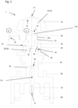
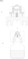
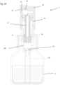
Figur 1 zeigt einen Pumpkopf I, der insbesondere als Dosierkopf für eine Quetschflasche geeignet ist. Der Pumpkopf I umfasst dabei ein Kopfteil 10 mit einer Auslassöffnung 11, die bevorzugt zur tropfenförmigen Abgabe von Fluiden ausgebildet sein kann. Ebenso ist es jedoch möglich, die Auslassöffnung so auszugestalten, dass ein Sprühnebel bei der Abgabe des Fluids erzeugbar ist. Das Kopfteil 10 sitzt dabei direkt auf einem Bauteil 40 auf und ist mit diesem form- und kraftschlüssig verbunden. Das Kopfteil 10 weist dabei eine innere Aussparung auf, die eine innere Oberfläche 12 aufweist. Zwischen Kopfteil 10 und Bauteil 40 ist ein elastisches Ventil 20 angeordnet, das einen Kopf 21a und eine elastische Wandung 21b aufweist. Das Ventil 20 ist in einem Lagerzustand (A) und einem Betätigungszustand (B) dargestellt. Erkennbar ist, dass im Betätigungszustand (B) die elastische Wandung 21b einknickt, hierzu enthält die elastische Wandung 21b eine Sollknickstelle 24, die im Betätigungszustand (B) ersichtlich sind. Im Lagerzustand (A) sind die Sollknickstellen 24 glatt gezogen. Der Kopf 21a des Ventils 20 kann dabei massiv ausgebildet sein, die elastische Wandung 21b als schlauchförmige Wandung an den Kopf 21a angefügt sein. Das komplett elastische Ventil 20 kann einstückig im Spritzgussverfahren hergestellt werden. An der elastischen Wandung 21b sind Fixierelemente 23, beispielsweise eine umlaufende Feder vorhanden. Über die Fixierelemente 23 ist das elastische Ventil 20 am Körper 40 fixiert. Hierzu werden die Fixierelemente 23 in korrespondierende Fixierelemente 43, beispielsweise eine umlaufende Nut, des Körpers 40 eingerastet. Die Oberfläche 22 des Kopfes 21a des Ventils 20 weist dabei eine identische Ausgestaltung auf, wie die innere Oberfläche 12 des Kopfteils 10, so dass der Kopf 21a des Ventils 20 im Lagerzustand (A) formschlüssig in das Kopfteil 10 eingreifen kann und somit die Auslassöffnung 11 vollständig verschließt. Hierdurch wird der im Betätigungszustand (B) ausgebildete Zwischenraum 10-20 zwischen Kopfteil 10 und elastischem Ventil 20 komplett verschlossen, sämtliches Fluid, das im Betätigungszustand zwischen Kopfteil 10 und elastischem Ventil 20 im Zwischenraum 10-20 vorhanden ist, wird bei Überführen des Pumpkopfes in den Lagerzustand aus der Auslassöffnung 11 ausgetragen. Das Bauteil 40 weist eine Wandung 42 auf, die baulich den Pumpkopf in einen oberen Teil (der Teil, der das Kopfteil und das elastische Ventil 20 umfasst) und einen unteren Teil (unterhalb der Wandung 42) trennt. Unterhalb der Wandung 42 des Bauteils 40 ist ein Bauteil 60 eingefügt, das formschlüssig mit dem Bauteil 40 verbindbar ist. Zwischen Bauteil 60 und Bauteil 40 resultiert ein Zwischenraum 40-60. Das Bauteil 40 weist dabei eine Durchlassöffnung 41 auf, die im beispielhaften, inFigur 1 dargestellten Fall derart ausgebildet ist, dass im unteren Teil des Bauteils 40 (auf Höhe des Zwischenraumes 40-60) die Durchlassöffnung 41 durch die Wandung 44 des Bauteils 40 durchgeführt ist und dort in einer (nicht dargestellten) Kerbe auf der äußeren Oberfläche des Bauteils 40 herum um das Bauteil 40 geführt ist. Die Kerbe kommuniziert dabei mit einem inFigur 1 links dargestellten, nach oben führenden Kanal, der in einer weiteren Durchlassöffnung 41 mündet, durch die das Fluid in den Zwischenraum 10-20 zwischen Ventil 20 und Kopfteil 10 führbar ist. Der auf der Oberfläche des Bauteils 40 geführte Kanal wird dabei vom aufgesteckten Bauteil 40 begrenzt und abgeschlossen.
Das Bauteil 60 verfügt über eine kopfseitig angebrachte Wandung 62, in die eine exzentrische Durchgangsöffnung 63 eingefügt ist. Das Bauteil 60 wird dabei soweit ins Bauteil 40 eingesteckt, dass die Wandung 62 nicht direkt mit der Wandung 42 des Bauteils 40 abschließt, sondern ein zwischenbleibender Bereich 40-60 erhalten bleibt und somit die Durchgangsöffnung 41, die im unteren Teil des Bauteils 40 angeordnet ist, geöffnet bleibt. Im beispielhaften Fall des Pumpkopfes I nachFigur 1 ist zwischen Bauteil 40 und Bauteil 60 ein bakterienfilterndes Material 50, über das ein Luftaustausch des innenliegenden Bereichs des Pumpkopfes mit der Umgebung möglich ist, angebracht. Das Bauteil 60 verfügt über eine Aussparung 61, in die ein Hohlkolben 70 mit einem inneren Hohlvolumen 71 eingebracht ist. Der Hohlkolben 70 ist dabei in axialer Richtung (inFigur 1 nach oben und unten) beweglich in der Aussparung 61 angeordnet. Zudem kann der Pumpkopf über ein Dichtungselement 80 verfügen, über das ein abdichtendes Anbringen des Pumpkopfes I auf einem inFigur 1 nicht dargestellten Vorratsgefäß II möglich ist. -
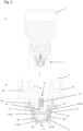
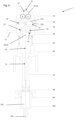
Figur 2 zeigt einen Pumpkopf I nachFigur 1 , der auf einem Vorratsgefäß II, im Falle derFigur 2 einer Quetschflasche, dargestellt ist. Das Vorratsgefäß II beinhaltet dabei ein abzugebendes Fluid, das inFigur 2a im Vorratsgefäß II schraffiert dargestellt ist.Figur 2a zeigt einen Schnitt durch die Gesamtanordnung im Gebrauchszustand,Figur 2b das inFigur 2a umrandete Detail des Pumpkopfes I. Hierbei wurden die gleichen Bezugszeichen wie inFigur 1 dargestellt verwendet. InFigur 2b ist mit dem Pfeil X, der durch den Durchtrittskanal 71 des Hohlkolbens 70, durch den Zwischenbereich 40-60 zwischen Bauteil 60 und Bauteil 40, durch die Durchtrittsöffnung 41, durch den Zwischenraum 10-20, der sich bei Betätigung der Dosiervorrichtung gemäßFigur 2 ergibt, und schließlich in Richtung der Auslassöffnung 11 der Weg des Fluids aus dem Vorratsbehältnis II Richtung Auslassöffnung 11 angedeutet. -
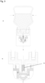
Figur 3 zeigt die gleiche Dosiervorrichtung gemäßFigur 2 bei Applikation eines Drucks (durch die Pfeile inFigur 3a angedeutet) auf die Quetschflasche II. Hierbei wird der Hohlkolben 70 (sieheFigur 3b ) nach unten gedrückt (durch den Pfeil links neben Hohlkolben 70 angedeutet) und somit das sich unterhalb des Hohlkolbens 70 befindliche, vom Hohlkolben 70 und Bauteil 60 eingeschlossene Fluid durch die Durchgangsöffnung 43 des Bauteils 60 in den Zwischenraum 40-60 eingepresst. InFigur 3 sind mit Ausnahme des Bezugszeichens 70 aus Gründen der Übersichtlichkeit keine weiteren Bezugszeichen eingefügt. Das Fluid 41 wird über die Durchgangsöffnung 41 weiter in den Zwischenraum 10-20 zwischen elastischem Ventil 20 und Kopfteil 10 des Pumpkopfes I eingepresst. Hierbei findet eine Deformation des elastischen Ventils statt, das wie inFigur 3b gezeigt, abknickt und somit die Auslassöffnung 11 freigibt, wodurch das Fluid austreten kann. Aufgrund der Tatsache, dass durch den Durchtrittskanal 71 des Hohlkolbens 70 und die Durchtrittsöffnung 63 des Bauteils 60 nicht deckungsgleich angeordnet sind, findet bei Anstoßen des Hohlkolbens 70 an der Wandung 62 des Bauteils 60 ein Verschluss der Durchtrittsöffnung 63 statt. Somit ist auch bei weiterer Applikation von Druck kein weiteres Austreten eines Fluids aus der Dosiervorrichtung möglich, da der Durchtrittskanal 63 verschlossen ist. Mit diesem Pumpkopf I ist somit eine dosierte Abgabe von Flüssigkeit aus einer Quetschflasche möglich. Der inFigur 3b dargestellte Zustand entspricht dem Betätigungszustand (B) des Pumpkopfes. -
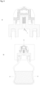
Figur 4 zeigt eine Ausführungsform, bei der eine Überführung der Dosiervorrichtung, insbesondere des Pumpkopfes, vom Betätigung- in den Lagerzustand erfolgt. Aus Gründen der Übersichtlichkeit sind keine Bezugszeichen dargestellt, es gelten jedoch die gleichen Ausführungen wie bei den vorstehenden Figuren.Figur 4a stellt dabei ein vergrößertes Detail der inFigur 4b dargestellten Dosiervorrichtung dar. Wie ausFigur 4a ersichtlich ist, ist der Hohlkolben 70 nach wie vor in der Endposition, die beim Betätigungsvorgang wie inFigur 3 dargestellt erreicht wird. Nach Beendigung des Betätigungsvorgangs kann die Dosiervorrichtung vom Benutzer in die Lagerposition überführt werden, wobei die Dosiervorrichtung, im Falle der Figur eine Quetschflasche, auf den Kopf gestellt wird. Hierbei lässt der Benutzer die Quetschflasche los, aufgrund der Rückstellkraft der Quetschflasche nimmt diese wieder ihre ursprüngliche Form, wie inFigur 2 dargestellt, ein. Die Rückstellkraft ist inFigur 4b durch die nach außen weisenden Pfeile dargestellt. Aufgrund des entnommenen Volumens an Flüssigkeit entsteht bei diesem Vorgang im Vorratsgefäß II ein Unterdruck, der sich über den Hohlkolben 70 in den Pumpkopf I der Dosiervorrichtung fortsetzt. Zum Druckausgleich wird über ein steriles Filter Luft in das Vorratsgefäß 2 eingesaugt. Bei diesem Vorgang wird auch der Hohlkolben 70 in seine Ausgangsposition zurückbewegt, d.h. im inFigur 4 dargestellten Fall wird der Hohlkolben 70 nach unten bewegt. Über das Bakterienfilter 50, das beispielsweise zwischen Bauteil 60 und Bauteil 40 vorhanden sein kann, ist ein Lufteintritt (Pfeil L) ins Innere des Vorratsgefäßes II, d.h. der Quetschflasche möglich. -
Figur 5 zeigt die Lagerposition (A) der Flasche, in der der Hohlkolben 70 in seiner Endposition dargestellt ist und die Quetschflasche II vollständig relaxiert ist (sieheFigur 5b ). -
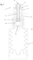
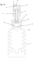
Figur 6 zeigt eine weitere Ausgestaltungsform eines erfindungsgemäßen Pumpkopfes, wobei die Bauteile 10, 20, 30 und 40 im Wesentlichen baugleich zu den entsprechenden Bauteilen nachFigur 1 ausgebildet sind. Die entsprechenden Bezugszeichen bezeichnen dabei identische Bauteile. Der wesentlichste Unterschied des Pumpkopfes I gemäßFigur 6 zum Pumpkopf I gemäßFigur 1 ist dabei, dass der Pumpkopf I gemäßFigur 6 aktiv betätigbar ist, d.h. die Bauteile 40 und 60 nicht fest miteinander verbunden sind, sondern über ein Federelement 55 gegeneinander beweglich ausgestaltet sind. Zur Ausführung dieser Bewegung umfasst das Kopfteil 10 dabei zusätzlich einen Griff 13, über den ein Benutzerdruck auf das Kopfteil ausüben kann und somit die Bauteile 10 bis 40 in Richtung des Bauteils 60 drücken kann. Im Unterschied zur Ausführungsform gemäßFigur 1 ist das Bauteil 60 dabei offen ausgebildet, d.h. weist keine nach oben abschließende Wandung 62 auf. Durch die Aussparung 61 des Bauteils 60 ist ein Hohlkolben 70 geführt, der einen Durchtrittskanal 71 aufweist. Der Hohlkolben mündet seinerseits in einem Pumpengehäuse 100, das ein Pumpenvolumen 101 und eine Einlassöffnung 102 aufweist. Bodenseitig an der Einlassöffnung ist ein Ventil 90, beispielsweise ein Scheibenventil angeordnet. Die Besonderheit des Pumpkopfes I gemäßFigur 6 liegt zudem darin, dass insbesondere die Bauteile 10, 40 und 60 hermetisch gegeneinander abgedichtet sind, so dass kein Luftaustausch der Inneren Volumina des Pumpkopfes I mit der Umgebung möglich ist. Beim Pumpkopf I gemäßFigur 6 handelt es sich somit um einen Airless-Pumpkopf. -
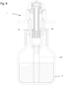
Figur 7 zeigt einen Anwendungsfall eines inFigur 6 dargestellten Pumpkopfes. Zur Vereinfachung sind lediglich die einzelnen Bestandteile mit Bezugszeichen gekennzeichnet, es gelten jedoch die identischen Ausführungsformen gemäßFigur 6 .
Betätigt ein Benutzer den Pumpkopf I in einer Dosiervorrichtung gemäßFigur 7 über den Griff 13, so wird zusammen mit dem Kopfteil 10 auch der gegenüber dem Bauteil 40 festgelegte Hohlkolben 70 nach unten in das Pumpengehäuse 100 gedrückt. Bei diesem Pumpvorgang bleibt das Ventil 90 verschlossen, so dass es zu einer Reduktion des Pumpenvolumens 101 kommt. Die im Volumen 101 befindliche Flüssigkeit wird dadurch durch den Durchtrittskanal 71 des Hohlkolbens 70 nach oben gepresst und entsprechend der bereits beiFigur 1 erläuterten Prinzipien durch die Durchtrittsöffnung 41 des Bauteils 40 und den sich ausbildenden Zwischenraum 10-20 zwischen Ventil 20 und Kopfteil 10 über die Auslassöffnung 11 ausgestoßen. Das Vorratsgefäß II ist in diesem Fall als starrer Behälter ausgebildet, in dem beispielsweise auch ein Faltenbalg 200 eingesetzt sein kann. -
Figur 8 zeigt eine Variante des Pumpkopfes gemäßFigur 6 in einem Non-Airless-System. Es gelten identische Bezugszeichen wie inFigur 6 dargestellt, lediglich baulich abweichende Bestandteile sind mit separaten Bezugszeichen angegeben. Im Gegensatz zum Pumpkopf I gemäßFigur 6 sind hierbei die Bauteile 40 und 60 nicht hermetisch gegeneinander abgedichtet ausgebildet, sondern es ist ein Bakterienfilter 50 zwischen Pumpteilen 40 und 60 eingebaut. Das im Bauteil 60 ist zudem ein Durchtrittskanal 51 für Luft vorhanden, wodurch Umgebungsluft über den Durchtrittskanal 51 ins Innere der Dosiervorrichtung eintreten kann. Der Durchtrittskanal 51 ist dabei im Betätigungszustand geöffnet und wird im Lagerzustand vom Hohlkolben 70 verschlossen. Die Betätigung des Pumpkopfes aus dem Lagerzustand in den Betriebszustand erfolgt gemäß den Ausführungen zurFigur 7 . Die im Vorratsbehältnis II bevorratete Inhaltslösung wird dabei mittels eines Steigrohres 110 in die Pumpkammer eingesaugt. -
Figur 9 zeigt eine weitere Variante eines erfindungsgemäßen Pumpkopfes I, der imFigur 9 dargestellten Fall zur seitlichen Abgabe von Flüssigkeiten ausgebildet ist. Der Pumpkopf I ist hierbei insbesondere als Sprühkopf ausgebildet, d.h. die Ausgangsöffnung 11 umfasst Mittel zur Erzeugung eines Sprühnebels einer abzugebenden Flüssigkeit. Das Kopfteil 10 ist hierbei als Einsatz im Bauteil 40 ausgebildet. Im Zwischenraum zwischen Bauteil 40 und Bauteil 10 ist das Ventil 20 angeordnet, das identisch ausgebildet ist, wie im beispielhaften Fall vonFigur 1 . Dargestellt sind ebenso die Betriebszustände (A) und (B) des Ventils 20, das ansonsten auf identische Weise wie inFigur 1 beschrieben funktioniert. Der Pumpkopf I gemäßFigur 1 ist dabei als Non-Airless-Pumpkopf ausgebildet, d.h. die Bauteile 40 und 60 sind beweglich gegenüber einander ausgebildet, jedoch nicht hermetisch dichtend. Somit ist ein Bakterienfilter 50 zur Filtration eintretender Luft zwischen Bauteilen 40 und 60 vorhanden. Bauteil 40 verfügt über eine Durchgangsöffnung, die direkt vom Zwischenraum 40-60 in den Zwischenraum 10-20 zwischen Ventil 20 und Kopfteil 10 führt. Die Funktionsweise der übrigen Bestandteile 70-110 wurde bereits eingehend mit Hinblick aufFiguren 6 bis 8 erläutert und ist auch im Falle derFigur 9 identisch. -
Figur 10 zeigt den Einbau des erfindungsgemäßen Pumpkopfes I gemäßFigur 9 in einem Non-Airless-System. Die Funktionsweise entspricht dabei der inFigur 8 dargestellten Funktionsweise. -
Figur 11 zeigt eine Variante des erfindungsgemäßen Pumpkopfes I gemäßFigur 9 als Airless-Pumpkopf. Hierbei ist kein Bakterienfilter 50 zwischen den Bauteilen 40 und 60 vorhanden, die Bauteile 40 und 60 sind dabei hermetisch dichtend übereinander gelagert, so dass kein Lufteintritt aus der Umgebung in den Innenraum des Pumpkopfes oder in das Vorratsbehältnis II stattfinden kann. Die Funktionsweise der Dosiervorrichtung ist ansonsten identisch mit der inFigur 7 dargestellten Funktionsweise.
Claims (15)
- Pumpkopf (I) für eine Dosiervorrichtung zur dosierten Abgabe eines Fluids, umfassendein Kopfteil (10) mit einer Austrittsöffnung (11) für das abzugebende Fluid, wobei das Kopfteil eine innere Oberfläche (12) aufweist,ein Ventil (20), das zumindest bereichsweise eine der inneren Oberfläche (12) des Kopfteils (10) entsprechende geometrische Ausgestaltung (22) aufweist,ein Bauteil (40), das eine Durchtrittsöffnung (41) für das abzugebende Fluid aufweist, über die ein Einströmen des Fluids zwischen Kopfteil (10) und Ventil (20) unter Ausbildung eines Zwischenraums (10-20) zwischen Ventil (20) und Kopfteil in einem Betätigungszustand (B) ermöglicht ist,wobei Kopfteil (10) und Bauteil (40) form- und kraftschlüssig unter Einschluss des Ventils (20) zwischen Kopfteil (10) und Bauteil (40) verbunden sind,dadurch gekennzeichnet, dassdas Ventil (20) elastisch ist,dass das Einströmen des Fluids unter Deformation des elastischen Ventils (20) ermöglicht wird,und dass das elastische Ventil (20) in einem Lagerzustand (A) des Pumpkopfes vollflächig formschlüssig auf der inneren Oberfläche (12) des Kopfteils (10) aufliegt, so dass eine fluidische Dichtung zwischen Kopfteil (10) und Bauteil (40) gewährleistet ist, und dassdas elastische Ventil einen Kopf (21a) und eine elastische Wandung (21b) umfasst, wobei der Kopf eine der inneren Oberfläche (12) des Kopfteils (10) entsprechende geometrische Ausgestaltung (22) aufweist und die elastische Wandung (21b) verformbar ausgebildet ist, wobeidie elastische Wandung (21b) mindestens eine Sollknickstelle (24) aufweist, an der die elastische Wandung (21b) bei einem Überführen vom Lager- (A) in den Betätigungszustand (B) ab- bzw. einknickt.
- Pumpkopf (I) nach Anspruch 1, dadurch gekennzeichnet, dass die elastische Wandung (21b) aus einem Film eines elastisch verformbaren Materials, insbesondere aus einem thermoplastischen Kunststoff, Gummi und/oder Silicon, bevorzugt mit einer Dicke von 0,03 bis 1 mm, bevorzugt 0,08 bis 0,5 mm, besonders bevorzugt 0,20 bis 0,30 mm gebildet ist und/oder der Kopf (21a) massiv ausgebildet ist.
- Pumpkopf (I) nach vorhergehendem Anspruch, dadurch gekennzeichnet, dass Kopf (21a) und elastische Wandung (21b) einstückig ausgebildet sind.
- Pumpkopf (I) nach einem der vorhergehenden Ansprüche, dadurch gekennzeichnet, dass das elastische Ventil (20) über mindestens ein Fixierelement (23) verfügt, über das das elastische Ventil (20) mit mindestens einem korrespondierendem Fixierelement (43) des Bauteils (40) kraftschlüssig verbunden ist, wobei bevorzugt das Fixierelement (23) des elastischen Ventils (20) und das Fixierelement (43) des Bauteils (40) als Einrastverbindung oder Schnappverbindung ausgebildet ist.
- Pumpkopf (I) nach einem der vorhergehenden Ansprüche, dadurch gekennzeichnet, dass das Bauteil (40) eine Wandung (42) aufweist, die den Zwischenraum (10-20) abschließt, wobei über die Durchtrittsöffnung (41) eine fluidische Kommunikation des Zwischenraums (10-20) mit einem vom Zwischenraum (10-20) aus gesehen jenseits der Wandung (42) liegenden Bereich (40-60) ermöglicht ist.
- Pumpkopf (I) nach vorhergehendem Anspruch, dadurch gekennzeichnet, dass die Durchtrittsöffnung (41) vom Bereich (40-60) unmittelbar durch die Wandung (42) geführt ist und in den Bereich (10-20) mündet, oder
im Bereich (40-60) durch eine seitliche Wandung (44) des Bauteils (40) durchgeführt wird, an einer äußeren Oberfläche des Bauteils (40) in einer Einkerbung, die vom Bauteil (10) begrenzt werden kann, geführt wird, und im Bereich (10-20) erneut durch die seitliche Wandung des Bauteils (40) geführt wird und in den Bereich (10-20) mündet. - Pumpkopf (I) nach einem der vorhergehenden Ansprüche, dadurch gekennzeichnet, dass zwischen elastischem Ventil (20) und Bauteil (40) ein Element (30), das eine Rückstellkraft auf das elastische Ventil (20) auswirkt, angeordnet ist, wobei die Rückstellkraft bewirkt, dass der im Betätigungszustand (B) ausgebildete Zwischenraum (10-20) unter Rückkehr in den Lagerzustand (A) geschlossen wird, wobei das Element (30) insbesondere eine Feder ist.
- Pumpkopf (I) nach einem der vorhergehenden Ansprüche, dadurch gekennzeichnet, dass das Bauteil (40) an seinem dem elastischen Ventil (20) abgewandten Ende mit einem Bauteil (60) verbunden ist, über das der Pumpkopf (I) mit einem Vorratsgefäß (II) zur Bevorratung des abzugebenden Fluids verbindbar ist, wobei insbesonderezwischen dem Bauteil (40) und dem Bauteil (60) mindestens ein Mittel (50) zur sterilen Filtration eintretender Luft vorhanden ist, insbesondere ein Bakterienfilter, oderdas Bauteil (40) gegenüber dem Bauteil (60) hermetisch dichtend ausgebildet ist.
- Pumpkopf (I) nach vorhergehendem Anspruch, dadurch gekennzeichnet, dass das Bauteil (40) gegenüber dem Bauteil (60)fixiert ist oderbeweglich ausgebildet ist, wobei zwischen dem Bauteil (40) und dem Bauteil (60) mindestens ein Mittel (55), das eine Rückstellkraft auf das Bauteil (40) ausübt, angeordnet ist, wobei das Bauteil (55) bevorzugt eine Feder ist.
- Pumpkopf (I) nach einem der vorhergehenden Ansprüche, dadurch gekennzeichnet, dass das Bauteil (60) eine Aussparung (61), die bevorzugt zylindrisch ausgebildet ist, aufweist, in der ein Hohlkolben (70) mit einem Durchtrittskanal (71) beweglich führbar ist.
- Pumpkopf (I) nach vorhergehendem Anspruch, dadurch gekennzeichnet, dass das Bauteil (60)eine gegenüber dem Bauteil (40) abschließend ausgebildete Wandung (62) aufweist, die eine Durchtrittsöffnung (63) aufweist, die mit einem beweglichen Hohlkolben (70) verschließbar ist, wobei durch die Wandung (62) ein zwischen Bauteil (40) und Bauteil (60) mit der Durchtrittsöffnung (41) in fluidischer Kommunikation stehender Bereich bzw. Zwischenraum (40-60) ausgebildet ist, odergegenüber dem Bauteil (40) offen ausgebildet ist, wobei der Hohlkolben (70) so im Bauteil (60) angeordnet ist, dass die Durchtrittsöffnung (41) nicht vom Hohlkolben (70) verschlossen wird.
- Pumpkopf (I) nach einem der beiden vorhergehenden Ansprüche, dadurch gekennzeichnet, dass der Hohlkolben (70) an seinem dem Bauteil (40) abgewandten Ende beweglich in ein Pumpgehäuse (100) geführt ist, das ein vom Pumpgehäuse (100) und Hohlkolben (70) definiertes Pumpvolumen (101) aufweist, wobei im Lagerzustand (A) das Pumpvolumen (101) maximiert und im Betätigungszustand (B) minimiert wird, wobei insbesonderedas Pumpgehäuse (100) einen bodenseitigen Einlass (102) umfasst, der bevorzugt mittels eines Ventils (90), insbesondere eines Scheibenventils oder Kugelventils während des Betätigungsvorgangs verschließbar und bei Überführen des Pumpkopfes vom Betätigungszustand (B) in den Lagerzustand (A) geöffnet werden kann, wobei insbesondeream bodenseitigen Einlass (102) ein Steigrohr (110) angeordnet ist.
- Pumpkopf (I) nach einem der vorhergehenden Ansprüche, dadurch gekennzeichnet, dass bei Verbindung des Pumpkopfes (I) über das Bauteil (60) mit dem Vorratsgefäß (II) eine Dichtung (80) zwischen Bauteil (60) und dem Vorratsgefäß (II), oder
über die Pumpkammer (100) mit dem Vorratsgefäß (II) eine Dichtung (80) zwischen Pumpkammer (100) und dem Vorratsgefäß (II)
angeordnet ist. - Pumpkopf (I) nach einem der vorhergehenden Ansprüche, dadurch gekennzeichnet, dass das Kopfteil (10) ein antibakterielles Material, bevorzugt Metalle oder Metallionen, insbesondere Silberpartikel oder Silberionen beinhaltet.
- Dosiervorrichtung, umfassend einen mit einem Vorratsgefäß (II) verbundenen Pumpkopf (I) nach einem der vorhergehenden Ansprüche, wobei insbesondere das Vorratsgefäß (II)als Quetschflasche oder als formfester Behälter ausgebildet ist, und/odereinen Innenbeutel (200), der gegenüber dem Pumpkopf (I) hermetisch abgedichtet ist, umfasst, wobei der Innenbeutel (200) insbesondere als Faltenbalg ausgebildet ist.
Priority Applications (4)
| Application Number | Priority Date | Filing Date | Title |
|---|---|---|---|
| PL17729067.3T PL3491345T5 (pl) | 2016-07-14 | 2017-06-01 | Głowica pompująca i urządzenie dozujące |
| RS20211290A RS62476B2 (sr) | 2016-07-14 | 2017-06-01 | Glava pumpe i dozirni uređaj |
| HRP20211695TT HRP20211695T4 (hr) | 2016-07-14 | 2017-06-01 | Glava pumpe i uređaj za doziranje |
| SI201730938T SI3491345T2 (sl) | 2016-07-14 | 2017-06-01 | Glava črpalke in dozirna naprava |
Applications Claiming Priority (2)
| Application Number | Priority Date | Filing Date | Title |
|---|---|---|---|
| DE102016212892.2A DE102016212892C5 (de) | 2016-07-14 | 2016-07-14 | Pumpkopf sowie Dosiervorrichtung |
| PCT/EP2017/063346 WO2018010890A1 (de) | 2016-07-14 | 2017-06-01 | Pumpkopf sowie dosiervorrichtung |
Publications (3)
| Publication Number | Publication Date |
|---|---|
| EP3491345A1 EP3491345A1 (de) | 2019-06-05 |
| EP3491345B1 EP3491345B1 (de) | 2021-08-04 |
| EP3491345B2 true EP3491345B2 (de) | 2024-10-16 |
Family
ID=59034750
Family Applications (1)
| Application Number | Title | Priority Date | Filing Date |
|---|---|---|---|
| EP17729067.3A Active EP3491345B2 (de) | 2016-07-14 | 2017-06-01 | Pumpkopf und dosiervorrichtung |
Country Status (20)
| Country | Link |
|---|---|
| US (1) | US11221248B2 (de) |
| EP (1) | EP3491345B2 (de) |
| KR (1) | KR102501071B1 (de) |
| CN (1) | CN109564123B (de) |
| AU (1) | AU2017295388B2 (de) |
| CA (1) | CA3027580C (de) |
| DE (1) | DE102016212892C5 (de) |
| DK (1) | DK3491345T4 (de) |
| ES (1) | ES2891540T5 (de) |
| FI (1) | FI3491345T4 (de) |
| HR (1) | HRP20211695T4 (de) |
| HU (1) | HUE056200T2 (de) |
| LT (1) | LT3491345T (de) |
| MX (1) | MX2019000587A (de) |
| PL (1) | PL3491345T5 (de) |
| PT (1) | PT3491345T (de) |
| RS (1) | RS62476B2 (de) |
| RU (1) | RU2737137C2 (de) |
| SI (1) | SI3491345T2 (de) |
| WO (1) | WO2018010890A1 (de) |
Families Citing this family (6)
| Publication number | Priority date | Publication date | Assignee | Title |
|---|---|---|---|---|
| DE102016212892C5 (de) | 2016-07-14 | 2020-01-30 | F. Holzer Gmbh | Pumpkopf sowie Dosiervorrichtung |
| DE102016212893A1 (de) * | 2016-07-14 | 2018-01-18 | F. Holzer Gmbh | Pumpkopf sowie Dosiervorrichtung |
| DE102018208110A1 (de) * | 2018-05-23 | 2019-11-28 | F. Holzer Gmbh | Abgabekopf und Abgabevorrichtung zur dosierten Abgabe flüssiger Präparate sowie Verwendungsmöglichkeiten |
| WO2019237162A1 (pt) * | 2018-06-12 | 2019-12-19 | Eric Zembrod | Dispositivo dispensador sem entrada de ar para bicos aplicadores de embalagens flexíveis diversas |
| DE102018216060A1 (de) * | 2018-09-20 | 2020-03-26 | F. Holzer Gmbh | Pumpkopf sowie Dosiervorrichtung |
| FR3160963A1 (fr) * | 2024-04-08 | 2025-10-10 | L'oreal | Tête de distribution de produit cosmétique, dispositif de conditionnement et de distribution, et procédé associé |
Citations (2)
| Publication number | Priority date | Publication date | Assignee | Title |
|---|---|---|---|---|
| DE102010063592A1 (de) † | 2010-12-20 | 2012-06-21 | Ing. Erich Pfeiffer Gmbh | Spender für Flüssigkeiten |
| DE102012217338A1 (de) † | 2012-09-25 | 2014-05-28 | Aptar Radolfzell Gmbh | Flüssigkeitsspender |
Family Cites Families (79)
| Publication number | Priority date | Publication date | Assignee | Title |
|---|---|---|---|---|
| US1592402A (en) * | 1924-10-01 | 1926-07-13 | Jr Harry A Wilcox | Self-closing nozzle for collapsible tubes |
| US1621097A (en) * | 1925-10-08 | 1927-03-15 | Salvatore J Zammataro | Collapsible tube |
| US2015794A (en) * | 1933-08-04 | 1935-10-01 | Louisa M Gilstrap | Self-sealing collapsible tube |
| US2026234A (en) * | 1933-11-16 | 1935-12-31 | Charles A Knuutila | Portable dispensing device |
| US2270794A (en) * | 1939-09-01 | 1942-01-20 | Feldmar Bela | Automatic closure for collapsible tubes |
| US2936935A (en) * | 1957-05-02 | 1960-05-17 | Irving L Rabb | Dispensing head |
| US3008611A (en) * | 1958-03-31 | 1961-11-14 | Chapman Machine Company Inc | Sealing and dispensing device |
| US3401719A (en) | 1966-03-31 | 1968-09-17 | Sylvania Electric Prod | Multiple bleed valve cartridge assembly |
| US3759425A (en) * | 1970-06-23 | 1973-09-18 | Cooper Mcdougall & Robertson | Piston valve syringe gun |
| JPS5425245B1 (de) | 1971-05-08 | 1979-08-27 | ||
| US4102476A (en) * | 1977-02-22 | 1978-07-25 | Ciba-Geigy Corporation | Squeeze bottle dispenser with air check valve on cover |
| DE3102346A1 (de) | 1981-01-24 | 1982-09-16 | Godax Laboratories, 10013 New York, N.Y. | "abfuellvorrichtung fuer fluessigkeiten" |
| US4420101A (en) * | 1981-11-18 | 1983-12-13 | Diamond International Corp. | Squeeze bottle with self-venting dispensing closure |
| US4739906A (en) * | 1986-07-14 | 1988-04-26 | Blairex Laboratories, Inc. | Storage bottle for contact lens cleaning solution having a self closing valve assembly |
| GB8825632D0 (en) * | 1988-11-02 | 1988-12-07 | Bespak Plc | Dispensing apparatus for pressurised dispensing containers |
| US4941598A (en) * | 1988-11-08 | 1990-07-17 | Ortho Pharmaceutical Corporation | Dosing cap |
| IL95500A (en) * | 1989-09-11 | 1997-03-18 | Matrix Pharma | ANTI-PROLIFERATIVE COMPOSITIONS CONTAINING TGF-b PROTEIN IN A VISCOUS MATRIX AND THEIR USE |
| FR2660877B1 (fr) * | 1990-04-13 | 1992-07-31 | Oreal | Ensemble de distribution d'au moins un produit liquide ou sous forme de creme. |
| US5370313A (en) | 1994-01-10 | 1994-12-06 | Beard; Walter C. | Sterile liquid dispenser |
| DE29506682U1 (de) * | 1995-04-19 | 1995-06-29 | Megaplast Dosiersysteme GmbH, 78052 Villingen-Schwenningen | Abgabepumpe aus Kunststoff für pastenartige Stoffe |
| AU1119797A (en) | 1995-11-16 | 1997-06-05 | Nordson Corporation | Method and apparatus for dispensing small amounts of liquid material |
| US6019114A (en) * | 1997-02-12 | 2000-02-01 | Icon Dynaamics, Llc | Self-metering reservoir |
| JP3732331B2 (ja) * | 1998-02-26 | 2006-01-05 | 株式会社吉野工業所 | 液体注出容器 |
| PT1102707E (pt) * | 1998-08-03 | 2003-02-28 | Veresk Biosystems Ltd | Valvula de recipiente |
| NL1010749C2 (nl) * | 1998-12-07 | 2000-06-08 | V O F Pharmasept | Houder voor het gedoseerd en in hoofdzaak kiemvrij afgeven van een vloeistof. |
| IT1310921B1 (it) * | 1999-06-24 | 2002-02-27 | Mrp Medical Res & Promotion Es | Flacone pluridose con beccuccio di dosaggio per liquidi,particolarmente prodotti farmaceutici. |
| FR2798650B1 (fr) | 1999-09-16 | 2002-01-04 | Oreal | Dispositif de distribution destine a equiper un recipient |
| FR2809712B1 (fr) | 2000-05-30 | 2002-07-26 | Oreal | Embout doseur pour la distribution d'une dose a volume variable et ensemble equipe d'un tel embout doseur |
| EP1295644B1 (de) | 2001-09-21 | 2008-12-10 | Ing. Erich Pfeiffer GmbH | Dosiervorrichtung mit einem Medienspeicher sowie einer Pumpvorrichtung |
| DE10200519A1 (de) * | 2002-01-09 | 2003-07-10 | Neomed Holding Sa Luxemburg Lu | Ventil |
| US7249694B2 (en) * | 2002-07-26 | 2007-07-31 | Masatoshi Masuda | Valve mechanism for tube-type fluid container |
| GB0229099D0 (en) * | 2002-12-13 | 2003-01-15 | Incro Ltd | Pump-action nozzle device |
| BRPI0407393A (pt) * | 2003-02-18 | 2006-02-07 | Incro Ltd | Dispositivo de bico acionável por bomba, recipiente, e método de fabricação de um dispositivo de bico |
| JP2007511295A (ja) * | 2003-11-14 | 2007-05-10 | メディカル・インスティル・テクノロジーズ・インコーポレイテッド | 注入装置及び注入方法 |
| NL1028730C2 (nl) * | 2004-09-16 | 2006-03-20 | Keltub B V | Samenstel van balg en tegendeel. |
| DE102004050977A1 (de) * | 2004-10-14 | 2006-04-20 | Ing. Erich Pfeiffer Gmbh | Dosiervorrichtung für wenigstens ein Medium |
| US20060231579A1 (en) | 2005-04-13 | 2006-10-19 | Carter Jeffrey M | Fluid dispenser |
| DE102006012302A1 (de) * | 2006-03-15 | 2007-09-27 | Seaquist Perfect Dispensing Gmbh | Abgabevorrichtung |
| ITMO20060252A1 (it) * | 2006-08-04 | 2008-02-05 | Mrp Medical Res & Promotion Es | Flacone per il contenimento di fluidi, particolarmente per prodotti farmaceutici o simili |
| EP1909077A1 (de) | 2006-10-02 | 2008-04-09 | Syngeta Participations AG | Flüssigkeitsdosiergerät |
| US8132695B2 (en) * | 2006-11-11 | 2012-03-13 | Medical Instill Technologies, Inc. | Multiple dose delivery device with manually depressible actuator and one-way valve for storing and dispensing substances, and related method |
| US20090008413A1 (en) * | 2007-04-17 | 2009-01-08 | Choi Hee Jin | Airless dispensing pump container with an airtight push down type nozzle head |
| JP4966723B2 (ja) | 2007-04-19 | 2012-07-04 | 株式会社吉野工業所 | 吐出ポンプ |
| DE102008027987A1 (de) * | 2008-03-04 | 2009-09-17 | Kist-Europe Forschungsgesellschaft Mbh | Dosierungsvorrichtung |
| FR2929249B1 (fr) * | 2008-03-27 | 2012-02-17 | Rexam Pharma La Verpilliere | Dispositif de distribution de liquide contenu dans un reservoir |
| CN102099122B (zh) * | 2008-05-20 | 2013-08-28 | G·桑尼尔 | 用于具有无空气储液箱的分配器的改进泵 |
| DE102008027146B4 (de) * | 2008-06-02 | 2012-01-19 | Ing. Erich Pfeiffer Gmbh | Austragvorrichtung |
| DE102009006431B4 (de) | 2009-01-23 | 2010-12-30 | Ing. Erich Pfeiffer Gmbh | Austragvorrichtung |
| US8985390B2 (en) * | 2009-09-18 | 2015-03-24 | The Procter & Gamble Company | Unit dose dispensing apparatus |
| DE102009048476B3 (de) * | 2009-10-07 | 2010-09-16 | Gaplast Gmbh | Einwegventil |
| BR112012011566A2 (pt) | 2009-10-09 | 2016-06-28 | Py Daniel C | dispositivo com fecho co-moldado, válvulas de sentido único, câmara de armazenamento de volume variável e método relacionado |
| US20110240677A1 (en) | 2010-03-03 | 2011-10-06 | Walter Dwyer | Airless double-piston double-action pump and cosmetics bottle dispensing device |
| CN103402650B (zh) * | 2010-03-17 | 2016-07-20 | Ipnip有限公司 | 具有部分分配装置的容器 |
| EP2383553A1 (de) | 2010-04-30 | 2011-11-02 | Nestec S.A. | Verpackung zur Lagerung und Dosierung einer Flüssigkeit |
| DE102010045059A1 (de) * | 2010-09-10 | 2012-03-15 | F. Holzer Gmbh | Dosiervorrichtung |
| DE102010048986A1 (de) * | 2010-10-20 | 2012-04-26 | Ursapharm Arzneimittel Gmbh | Dosierpumpe |
| DE102011106261A1 (de) * | 2011-05-18 | 2012-11-22 | Meadwestvaco Calmar Gmbh | Spender zur dosierten Abgabe von flüssigen Medien |
| US20140231462A1 (en) | 2013-02-18 | 2014-08-21 | Gojo Industries, Inc. | Metered dose squeeze dispenser |
| KR101550698B1 (ko) * | 2013-03-18 | 2015-09-08 | 에프. 홀저 게엠베하 | 약제 디스펜서 |
| KR101551192B1 (ko) * | 2013-06-14 | 2015-09-21 | 에프. 홀저 게엠베하 | 약제 디스펜서 |
| CN104058180B (zh) * | 2013-03-18 | 2017-03-01 | F·霍尔泽有限责任公司 | 药剂分配器 |
| DE102013211423A1 (de) | 2013-06-18 | 2014-12-31 | Aptar Radolfzell Gmbh | Mehrschichtiger Behälter |
| US9676525B2 (en) | 2013-12-17 | 2017-06-13 | Aptar Radolfzell Gmbh | Protective cap for a dispenser, and discharge device for discharging pharmaceutical and/or cosmetical liquids |
| DE102013226253B4 (de) | 2013-12-17 | 2016-03-24 | Aptar Radolfzell Gmbh | Schutzkappe für einen Spender und Spender zum Austrag von pharmazeutischen und/oder kosmetischen Flüssigkeiten |
| US9669974B2 (en) | 2013-12-17 | 2017-06-06 | Aptar Radolfzell Gmbh | Protective cap for a dispenser, and discharge device for discharging pharmaceutical and/or cosmetical liquids |
| DE102013226250B4 (de) | 2013-12-17 | 2019-07-18 | Aptar Radolfzell Gmbh | Schutzkappe für einen Spender und Austragvorrichtung umfassend einen Spender zum Austrag von pharmazeutischen und/oder kosmetischen Flüssigkeiten |
| DE102014206568A1 (de) | 2014-04-04 | 2015-10-08 | Aptar Radolfzell Gmbh | Dosiereinrichtung für einen Flüssigkeitsspender und Flüssigkeitsspender mit einer solchen |
| DK2992967T3 (da) * | 2014-09-02 | 2020-08-31 | F Holzer Gmbh | Medikamentdispenser |
| DE102014221393A1 (de) | 2014-10-21 | 2016-04-21 | F. Holzer Gmbh | Pumpkopf für eine Dosiervorrichtung, Dosiervorrichtung sowie Verwendungsmöglichkeiten |
| EP3023752A1 (de) | 2014-11-18 | 2016-05-25 | Aptar Radolfzell GmbH | Flüssigkeitsspender und Austragkopf hierfür |
| GB201507687D0 (en) * | 2015-04-30 | 2015-06-17 | Leafgreen Ltd | Pulsed spray nozzle arrangement |
| CN105057139B (zh) | 2015-07-23 | 2017-09-26 | 郭磊 | 一种微型电动喷雾器 |
| WO2017029467A1 (en) * | 2015-08-14 | 2017-02-23 | Leafgreen Limited | Pulsed spray nozzle arrangements |
| JP6944376B2 (ja) * | 2015-11-20 | 2021-10-06 | 武内プレス工業株式会社 | 逆止弁構造、それを用いたノズル部材およびスクイズ容器 |
| DE102016212892C5 (de) | 2016-07-14 | 2020-01-30 | F. Holzer Gmbh | Pumpkopf sowie Dosiervorrichtung |
| DE102016212893A1 (de) * | 2016-07-14 | 2018-01-18 | F. Holzer Gmbh | Pumpkopf sowie Dosiervorrichtung |
| FR3068897A1 (fr) * | 2017-07-17 | 2019-01-18 | Albea Services | Tete de distribution de produit provenant d'un recipient |
| KR101866230B1 (ko) | 2018-03-16 | 2018-06-15 | (주)연우 | 액체 배출 용기 |
| KR101866233B1 (ko) | 2018-03-16 | 2018-06-12 | (주)연우 | 액체 배출 용기 |
-
2016
- 2016-07-14 DE DE102016212892.2A patent/DE102016212892C5/de active Active
-
2017
- 2017-06-01 WO PCT/EP2017/063346 patent/WO2018010890A1/de not_active Ceased
- 2017-06-01 DK DK17729067.3T patent/DK3491345T4/da active
- 2017-06-01 RS RS20211290A patent/RS62476B2/sr unknown
- 2017-06-01 HR HRP20211695TT patent/HRP20211695T4/hr unknown
- 2017-06-01 PL PL17729067.3T patent/PL3491345T5/pl unknown
- 2017-06-01 AU AU2017295388A patent/AU2017295388B2/en active Active
- 2017-06-01 RU RU2018145139A patent/RU2737137C2/ru active
- 2017-06-01 SI SI201730938T patent/SI3491345T2/sl unknown
- 2017-06-01 KR KR1020197000845A patent/KR102501071B1/ko active Active
- 2017-06-01 HU HUE17729067A patent/HUE056200T2/hu unknown
- 2017-06-01 PT PT17729067T patent/PT3491345T/pt unknown
- 2017-06-01 LT LTEPPCT/EP2017/063346T patent/LT3491345T/lt unknown
- 2017-06-01 EP EP17729067.3A patent/EP3491345B2/de active Active
- 2017-06-01 FI FIEP17729067.3T patent/FI3491345T4/fi active
- 2017-06-01 MX MX2019000587A patent/MX2019000587A/es unknown
- 2017-06-01 CA CA3027580A patent/CA3027580C/en active Active
- 2017-06-01 CN CN201780043716.1A patent/CN109564123B/zh active Active
- 2017-06-01 ES ES17729067T patent/ES2891540T5/es active Active
- 2017-06-01 US US16/315,364 patent/US11221248B2/en active Active
Patent Citations (2)
| Publication number | Priority date | Publication date | Assignee | Title |
|---|---|---|---|---|
| DE102010063592A1 (de) † | 2010-12-20 | 2012-06-21 | Ing. Erich Pfeiffer Gmbh | Spender für Flüssigkeiten |
| DE102012217338A1 (de) † | 2012-09-25 | 2014-05-28 | Aptar Radolfzell Gmbh | Flüssigkeitsspender |
Also Published As
Similar Documents
| Publication | Publication Date | Title |
|---|---|---|
| EP3491345B2 (de) | Pumpkopf und dosiervorrichtung | |
| EP2236213B1 (de) | Austragvorrichtung | |
| EP2200752B1 (de) | Dosierungsvorrichtung | |
| DE2725495A1 (de) | Spendeeinrichtung | |
| DE2313755A1 (de) | Handbetaetigte spray-einrichtung | |
| DE2753603B2 (de) | Handbetfitigbare Abgabepumpe für Flüssigkeiten | |
| DE10200593A1 (de) | Betätigungskopf einer Saug-Druck-Pumpe zum Ausspritzen eines Produkts aus einem Behältnis | |
| DE69420956T2 (de) | Vorrichtung zur Abgabe von pastösen oder flüssigen Substanzen aus Flaschen oder ähnlichen Behältern | |
| EP3209427B1 (de) | Pumpkopf für eine dosiervorrichtung, dosiervorrichtung sowie verwendungsmöglichkeiten | |
| EP3485236B1 (de) | Pumpkopf sowie dosiervorrichtung | |
| DE8715785U1 (de) | Ventil | |
| EP1091809B1 (de) | Applikations-vorrichtung für keimfreie fluide | |
| DE20203841U1 (de) | Abgabevorrichtung für eine flüssige medikamentöse Zusammensetzung | |
| EP1514608B1 (de) | Dosiervorrichtung mit einem elastischen Betätigungsglied | |
| EP3023752A1 (de) | Flüssigkeitsspender und Austragkopf hierfür | |
| EP1616631A2 (de) | Dosiervorrichtung für Medien | |
| DE602004003339T2 (de) | Pumpe | |
| DE102007060359A1 (de) | Abgabevorrichtung | |
| CH616382A5 (en) | Nebulising device for liquids | |
| DE102008052589A1 (de) | Pumpvorrichtung | |
| DE102018216060A1 (de) | Pumpkopf sowie Dosiervorrichtung | |
| DE19724261A1 (de) | Flüssigkeitsdispenser, Förder- oder Dosierzylindervorrichtung, insbesondere für einen Flüssigkeitsdispenser und Verfahren zur Herstellung eines Flüssigkeitsdispensers | |
| DE1802746A1 (de) | Abgabevorrichtung,insbesondere fuer Aerosole mit einem durch den Treibmittelbehaelter hindurch verlaufenden Zufuhrrohr | |
| EP1630417B1 (de) | Spendevorrichtung für flüssige, rieselförmige und pastöse Medien | |
| EP3730219A1 (de) | Spender zum austrag pharmazeutischer flüssigkeiten |
Legal Events
| Date | Code | Title | Description |
|---|---|---|---|
| REG | Reference to a national code |
Ref country code: HR Ref legal event code: TUEP Ref document number: P20211695T Country of ref document: HR |
|
| STAA | Information on the status of an ep patent application or granted ep patent |
Free format text: STATUS: UNKNOWN |
|
| STAA | Information on the status of an ep patent application or granted ep patent |
Free format text: STATUS: THE INTERNATIONAL PUBLICATION HAS BEEN MADE |
|
| PUAI | Public reference made under article 153(3) epc to a published international application that has entered the european phase |
Free format text: ORIGINAL CODE: 0009012 |
|
| STAA | Information on the status of an ep patent application or granted ep patent |
Free format text: STATUS: REQUEST FOR EXAMINATION WAS MADE |
|
| 17P | Request for examination filed |
Effective date: 20190130 |
|
| AK | Designated contracting states |
Kind code of ref document: A1 Designated state(s): AL AT BE BG CH CY CZ DE DK EE ES FI FR GB GR HR HU IE IS IT LI LT LU LV MC MK MT NL NO PL PT RO RS SE SI SK SM TR |
|
| AX | Request for extension of the european patent |
Extension state: BA ME |
|
| DAV | Request for validation of the european patent (deleted) | ||
| DAX | Request for extension of the european patent (deleted) | ||
| STAA | Information on the status of an ep patent application or granted ep patent |
Free format text: STATUS: EXAMINATION IS IN PROGRESS |
|
| 17Q | First examination report despatched |
Effective date: 20200416 |
|
| GRAP | Despatch of communication of intention to grant a patent |
Free format text: ORIGINAL CODE: EPIDOSNIGR1 |
|
| STAA | Information on the status of an ep patent application or granted ep patent |
Free format text: STATUS: GRANT OF PATENT IS INTENDED |
|
| INTG | Intention to grant announced |
Effective date: 20210122 |
|
| GRAS | Grant fee paid |
Free format text: ORIGINAL CODE: EPIDOSNIGR3 |
|
| GRAA | (expected) grant |
Free format text: ORIGINAL CODE: 0009210 |
|
| STAA | Information on the status of an ep patent application or granted ep patent |
Free format text: STATUS: THE PATENT HAS BEEN GRANTED |
|
| AK | Designated contracting states |
Kind code of ref document: B1 Designated state(s): AL AT BE BG CH CY CZ DE DK EE ES FI FR GB GR HR HU IE IS IT LI LT LU LV MC MK MT NL NO PL PT RO RS SE SI SK SM TR |
|
| REG | Reference to a national code |
Ref country code: GB Ref legal event code: FG4D Free format text: NOT ENGLISH |
|
| REG | Reference to a national code |
Ref country code: AT Ref legal event code: REF Ref document number: 1417419 Country of ref document: AT Kind code of ref document: T Effective date: 20210815 |
|
| REG | Reference to a national code |
Ref country code: CH Ref legal event code: EP |
|
| REG | Reference to a national code |
Ref country code: DE Ref legal event code: R096 Ref document number: 502017011100 Country of ref document: DE |
|
| REG | Reference to a national code |
Ref country code: IE Ref legal event code: FG4D Free format text: LANGUAGE OF EP DOCUMENT: GERMAN |
|
| REG | Reference to a national code |
Ref country code: PT Ref legal event code: SC4A Ref document number: 3491345 Country of ref document: PT Date of ref document: 20211004 Kind code of ref document: T Free format text: AVAILABILITY OF NATIONAL TRANSLATION Effective date: 20210928 |
|
| REG | Reference to a national code |
Ref country code: DK Ref legal event code: T3 Effective date: 20211013 |
|
| REG | Reference to a national code |
Ref country code: FI Ref legal event code: FGE |
|
| REG | Reference to a national code |
Ref country code: NO Ref legal event code: T2 Effective date: 20210804 |
|
| REG | Reference to a national code |
Ref country code: SE Ref legal event code: TRGR |
|
| REG | Reference to a national code |
Ref country code: EE Ref legal event code: FG4A Ref document number: E021431 Country of ref document: EE Effective date: 20211006 |
|
| REG | Reference to a national code |
Ref country code: NL Ref legal event code: FP |
|
| REG | Reference to a national code |
Ref country code: GR Ref legal event code: EP Ref document number: 20210402835 Country of ref document: GR Effective date: 20211209 |
|
| REG | Reference to a national code |
Ref country code: SK Ref legal event code: T3 Ref document number: E 38469 Country of ref document: SK |
|
| REG | Reference to a national code |
Ref country code: HU Ref legal event code: AG4A Ref document number: E056200 Country of ref document: HU Ref country code: ES Ref legal event code: FG2A Ref document number: 2891540 Country of ref document: ES Kind code of ref document: T3 Effective date: 20220128 |
|
| REG | Reference to a national code |
Ref country code: HR Ref legal event code: T1PR Ref document number: P20211695 Country of ref document: HR |
|
| PG25 | Lapsed in a contracting state [announced via postgrant information from national office to epo] |
Ref country code: LV Free format text: LAPSE BECAUSE OF FAILURE TO SUBMIT A TRANSLATION OF THE DESCRIPTION OR TO PAY THE FEE WITHIN THE PRESCRIBED TIME-LIMIT Effective date: 20210804 |
|
| REG | Reference to a national code |
Ref country code: DE Ref legal event code: R026 Ref document number: 502017011100 Country of ref document: DE |
|
| PLBI | Opposition filed |
Free format text: ORIGINAL CODE: 0009260 |
|
| PLAX | Notice of opposition and request to file observation + time limit sent |
Free format text: ORIGINAL CODE: EPIDOSNOBS2 |
|
| PG25 | Lapsed in a contracting state [announced via postgrant information from national office to epo] |
Ref country code: SM Free format text: LAPSE BECAUSE OF FAILURE TO SUBMIT A TRANSLATION OF THE DESCRIPTION OR TO PAY THE FEE WITHIN THE PRESCRIBED TIME-LIMIT Effective date: 20210804 Ref country code: AL Free format text: LAPSE BECAUSE OF FAILURE TO SUBMIT A TRANSLATION OF THE DESCRIPTION OR TO PAY THE FEE WITHIN THE PRESCRIBED TIME-LIMIT Effective date: 20210804 |
|
| REG | Reference to a national code |
Ref country code: FI Ref legal event code: MDE Opponent name: APTAR RADOLFZELL GMBH |
|
| 26 | Opposition filed |
Opponent name: APTAR RADOLFZELL GMBH Effective date: 20220502 |
|
| REG | Reference to a national code |
Ref country code: HR Ref legal event code: ODRP Ref document number: P20211695 Country of ref document: HR Payment date: 20220526 Year of fee payment: 6 |
|
| PLBB | Reply of patent proprietor to notice(s) of opposition received |
Free format text: ORIGINAL CODE: EPIDOSNOBS3 |
|
| REG | Reference to a national code |
Ref country code: EE Ref legal event code: MM4A Ref document number: E021431 Country of ref document: EE Effective date: 20220630 |
|
| PG25 | Lapsed in a contracting state [announced via postgrant information from national office to epo] |
Ref country code: EE Free format text: LAPSE BECAUSE OF NON-PAYMENT OF DUE FEES Effective date: 20220630 |
|
| REG | Reference to a national code |
Ref country code: HR Ref legal event code: ODRP Ref document number: P20211695 Country of ref document: HR Payment date: 20230524 Year of fee payment: 7 |
|
| P01 | Opt-out of the competence of the unified patent court (upc) registered |
Effective date: 20230417 |
|
| P02 | Opt-out of the competence of the unified patent court (upc) changed |
Effective date: 20230508 |
|
| PLAB | Opposition data, opponent's data or that of the opponent's representative modified |
Free format text: ORIGINAL CODE: 0009299OPPO |
|
| R26 | Opposition filed (corrected) |
Opponent name: APTAR RADOLFZELL GMBH Effective date: 20220502 |
|
| APBM | Appeal reference recorded |
Free format text: ORIGINAL CODE: EPIDOSNREFNO |
|
| APBP | Date of receipt of notice of appeal recorded |
Free format text: ORIGINAL CODE: EPIDOSNNOA2O |
|
| APAH | Appeal reference modified |
Free format text: ORIGINAL CODE: EPIDOSCREFNO |
|
| PG25 | Lapsed in a contracting state [announced via postgrant information from national office to epo] |
Ref country code: MK Free format text: LAPSE BECAUSE OF FAILURE TO SUBMIT A TRANSLATION OF THE DESCRIPTION OR TO PAY THE FEE WITHIN THE PRESCRIBED TIME-LIMIT Effective date: 20210804 Ref country code: CY Free format text: LAPSE BECAUSE OF FAILURE TO SUBMIT A TRANSLATION OF THE DESCRIPTION OR TO PAY THE FEE WITHIN THE PRESCRIBED TIME-LIMIT Effective date: 20210804 |
|
| APBU | Appeal procedure closed |
Free format text: ORIGINAL CODE: EPIDOSNNOA9O |
|
| REG | Reference to a national code |
Ref country code: HR Ref legal event code: ODRP Ref document number: P20211695 Country of ref document: HR Payment date: 20240523 Year of fee payment: 8 |
|
| PUAH | Patent maintained in amended form |
Free format text: ORIGINAL CODE: 0009272 |
|
| STAA | Information on the status of an ep patent application or granted ep patent |
Free format text: STATUS: PATENT MAINTAINED AS AMENDED |
|
| 27A | Patent maintained in amended form |
Effective date: 20241016 |
|
| AK | Designated contracting states |
Kind code of ref document: B2 Designated state(s): AL AT BE BG CH CY CZ DE DK EE ES FI FR GB GR HR HU IE IS IT LI LT LU LV MC MK MT NL NO PL PT RO RS SE SI SK SM TR |
|
| REG | Reference to a national code |
Ref country code: DE Ref legal event code: R102 Ref document number: 502017011100 Country of ref document: DE |
|
| REG | Reference to a national code |
Ref country code: SK Ref legal event code: T5 Ref document number: E 38469 Country of ref document: SK |
|
| REG | Reference to a national code |
Ref country code: SE Ref legal event code: RPEO |
|
| REG | Reference to a national code |
Ref country code: DK Ref legal event code: T4 Effective date: 20250115 |
|
| REG | Reference to a national code |
Ref country code: NL Ref legal event code: FP |
|
| REG | Reference to a national code |
Ref country code: GR Ref legal event code: EP Ref document number: 20240402758 Country of ref document: GR Effective date: 20250120 |
|
| REG | Reference to a national code |
Ref country code: HR Ref legal event code: T4IZ Ref document number: P20211695 Country of ref document: HR |
|
| REG | Reference to a national code |
Ref country code: ES Ref legal event code: DC2A Ref document number: 2891540 Country of ref document: ES Kind code of ref document: T5 Effective date: 20250303 |
|
| REG | Reference to a national code |
Ref country code: HR Ref legal event code: ODRP Ref document number: P20211695 Country of ref document: HR Payment date: 20250522 Year of fee payment: 9 |
|
| PGFP | Annual fee paid to national office [announced via postgrant information from national office to epo] |
Ref country code: MC Payment date: 20250624 Year of fee payment: 9 |
|
| PGFP | Annual fee paid to national office [announced via postgrant information from national office to epo] |
Ref country code: FI Payment date: 20250627 Year of fee payment: 9 |
|
| PGFP | Annual fee paid to national office [announced via postgrant information from national office to epo] |
Ref country code: PL Payment date: 20250522 Year of fee payment: 9 Ref country code: DE Payment date: 20250625 Year of fee payment: 9 |
|
| PGFP | Annual fee paid to national office [announced via postgrant information from national office to epo] |
Ref country code: GB Payment date: 20250618 Year of fee payment: 9 Ref country code: DK Payment date: 20250625 Year of fee payment: 9 |
|
| PGFP | Annual fee paid to national office [announced via postgrant information from national office to epo] |
Ref country code: LT Payment date: 20250523 Year of fee payment: 9 |
|
| PGFP | Annual fee paid to national office [announced via postgrant information from national office to epo] |
Ref country code: RS Payment date: 20250522 Year of fee payment: 9 Ref country code: NO Payment date: 20250624 Year of fee payment: 9 |
|
| PGFP | Annual fee paid to national office [announced via postgrant information from national office to epo] |
Ref country code: NL Payment date: 20250618 Year of fee payment: 9 Ref country code: LU Payment date: 20250627 Year of fee payment: 9 Ref country code: BE Payment date: 20250618 Year of fee payment: 9 |
|
| PGFP | Annual fee paid to national office [announced via postgrant information from national office to epo] |
Ref country code: HR Payment date: 20250522 Year of fee payment: 9 |
|
| PGFP | Annual fee paid to national office [announced via postgrant information from national office to epo] |
Ref country code: PT Payment date: 20250522 Year of fee payment: 9 |
|
| PGFP | Annual fee paid to national office [announced via postgrant information from national office to epo] |
Ref country code: HU Payment date: 20250620 Year of fee payment: 9 Ref country code: FR Payment date: 20250625 Year of fee payment: 9 |
|
| PGFP | Annual fee paid to national office [announced via postgrant information from national office to epo] |
Ref country code: MT Payment date: 20250529 Year of fee payment: 9 Ref country code: BG Payment date: 20250619 Year of fee payment: 9 Ref country code: GR Payment date: 20250620 Year of fee payment: 9 |
|
| PGFP | Annual fee paid to national office [announced via postgrant information from national office to epo] |
Ref country code: RO Payment date: 20250527 Year of fee payment: 9 Ref country code: AT Payment date: 20250620 Year of fee payment: 9 |
|
| PGFP | Annual fee paid to national office [announced via postgrant information from national office to epo] |
Ref country code: TR Payment date: 20250526 Year of fee payment: 9 Ref country code: SK Payment date: 20250527 Year of fee payment: 9 |
|
| PGFP | Annual fee paid to national office [announced via postgrant information from national office to epo] |
Ref country code: CZ Payment date: 20250528 Year of fee payment: 9 |
|
| PGFP | Annual fee paid to national office [announced via postgrant information from national office to epo] |
Ref country code: IE Payment date: 20250618 Year of fee payment: 9 |
|
| PGFP | Annual fee paid to national office [announced via postgrant information from national office to epo] |
Ref country code: SI Payment date: 20250522 Year of fee payment: 9 Ref country code: SE Payment date: 20250618 Year of fee payment: 9 |
|
| PGFP | Annual fee paid to national office [announced via postgrant information from national office to epo] |
Ref country code: ES Payment date: 20250728 Year of fee payment: 9 |
|
| PGFP | Annual fee paid to national office [announced via postgrant information from national office to epo] |
Ref country code: IT Payment date: 20250624 Year of fee payment: 9 |
|
| PGFP | Annual fee paid to national office [announced via postgrant information from national office to epo] |
Ref country code: CH Payment date: 20250701 Year of fee payment: 9 |