EP3473601B1 - Apparatus for producing reforming liquid and method for producing reforming liquid - Google Patents
Apparatus for producing reforming liquid and method for producing reforming liquid Download PDFInfo
- Publication number
- EP3473601B1 EP3473601B1 EP17813073.8A EP17813073A EP3473601B1 EP 3473601 B1 EP3473601 B1 EP 3473601B1 EP 17813073 A EP17813073 A EP 17813073A EP 3473601 B1 EP3473601 B1 EP 3473601B1
- Authority
- EP
- European Patent Office
- Prior art keywords
- liquid
- electrode
- treatment tank
- wall
- central axis
- Prior art date
- Legal status (The legal status is an assumption and is not a legal conclusion. Google has not performed a legal analysis and makes no representation as to the accuracy of the status listed.)
- Active
Links
Images


Classifications
-
- C—CHEMISTRY; METALLURGY
- C02—TREATMENT OF WATER, WASTE WATER, SEWAGE, OR SLUDGE
- C02F—TREATMENT OF WATER, WASTE WATER, SEWAGE, OR SLUDGE
- C02F1/00—Treatment of water, waste water, or sewage
- C02F1/46—Treatment of water, waste water, or sewage by electrochemical methods
- C02F1/4608—Treatment of water, waste water, or sewage by electrochemical methods using electrical discharges
-
- C—CHEMISTRY; METALLURGY
- C02—TREATMENT OF WATER, WASTE WATER, SEWAGE, OR SLUDGE
- C02F—TREATMENT OF WATER, WASTE WATER, SEWAGE, OR SLUDGE
- C02F1/00—Treatment of water, waste water, or sewage
- C02F1/30—Treatment of water, waste water, or sewage by irradiation
-
- H—ELECTRICITY
- H05—ELECTRIC TECHNIQUES NOT OTHERWISE PROVIDED FOR
- H05H—PLASMA TECHNIQUE; PRODUCTION OF ACCELERATED ELECTRICALLY-CHARGED PARTICLES OR OF NEUTRONS; PRODUCTION OR ACCELERATION OF NEUTRAL MOLECULAR OR ATOMIC BEAMS
- H05H1/00—Generating plasma; Handling plasma
- H05H1/24—Generating plasma
- H05H1/247—Generating plasma using discharges in liquid media
-
- H—ELECTRICITY
- H05—ELECTRIC TECHNIQUES NOT OTHERWISE PROVIDED FOR
- H05H—PLASMA TECHNIQUE; PRODUCTION OF ACCELERATED ELECTRICALLY-CHARGED PARTICLES OR OF NEUTRONS; PRODUCTION OR ACCELERATION OF NEUTRAL MOLECULAR OR ATOMIC BEAMS
- H05H1/00—Generating plasma; Handling plasma
- H05H1/24—Generating plasma
- H05H1/26—Plasma torches
- H05H1/32—Plasma torches using an arc
- H05H1/34—Details, e.g. electrodes, nozzles
- H05H1/3468—Vortex generators
-
- H—ELECTRICITY
- H05—ELECTRIC TECHNIQUES NOT OTHERWISE PROVIDED FOR
- H05H—PLASMA TECHNIQUE; PRODUCTION OF ACCELERATED ELECTRICALLY-CHARGED PARTICLES OR OF NEUTRONS; PRODUCTION OR ACCELERATION OF NEUTRAL MOLECULAR OR ATOMIC BEAMS
- H05H1/00—Generating plasma; Handling plasma
- H05H1/24—Generating plasma
- H05H1/48—Generating plasma using an arc
-
- C—CHEMISTRY; METALLURGY
- C02—TREATMENT OF WATER, WASTE WATER, SEWAGE, OR SLUDGE
- C02F—TREATMENT OF WATER, WASTE WATER, SEWAGE, OR SLUDGE
- C02F2201/00—Apparatus for treatment of water, waste water or sewage
- C02F2201/46—Apparatus for electrochemical processes
- C02F2201/461—Electrolysis apparatus
- C02F2201/46105—Details relating to the electrolytic devices
- C02F2201/4611—Fluid flow
-
- C—CHEMISTRY; METALLURGY
- C02—TREATMENT OF WATER, WASTE WATER, SEWAGE, OR SLUDGE
- C02F—TREATMENT OF WATER, WASTE WATER, SEWAGE, OR SLUDGE
- C02F2201/00—Apparatus for treatment of water, waste water or sewage
- C02F2201/46—Apparatus for electrochemical processes
- C02F2201/461—Electrolysis apparatus
- C02F2201/46105—Details relating to the electrolytic devices
- C02F2201/4616—Power supply
- C02F2201/46175—Electrical pulses
-
- C—CHEMISTRY; METALLURGY
- C02—TREATMENT OF WATER, WASTE WATER, SEWAGE, OR SLUDGE
- C02F—TREATMENT OF WATER, WASTE WATER, SEWAGE, OR SLUDGE
- C02F2301/00—General aspects of water treatment
- C02F2301/02—Fluid flow conditions
- C02F2301/026—Spiral, helicoidal, radial
-
- C—CHEMISTRY; METALLURGY
- C02—TREATMENT OF WATER, WASTE WATER, SEWAGE, OR SLUDGE
- C02F—TREATMENT OF WATER, WASTE WATER, SEWAGE, OR SLUDGE
- C02F2303/00—Specific treatment goals
- C02F2303/02—Odour removal or prevention of malodour
-
- C—CHEMISTRY; METALLURGY
- C02—TREATMENT OF WATER, WASTE WATER, SEWAGE, OR SLUDGE
- C02F—TREATMENT OF WATER, WASTE WATER, SEWAGE, OR SLUDGE
- C02F2303/00—Specific treatment goals
- C02F2303/04—Disinfection
-
- C—CHEMISTRY; METALLURGY
- C02—TREATMENT OF WATER, WASTE WATER, SEWAGE, OR SLUDGE
- C02F—TREATMENT OF WATER, WASTE WATER, SEWAGE, OR SLUDGE
- C02F2305/00—Use of specific compounds during water treatment
- C02F2305/02—Specific form of oxidant
- C02F2305/023—Reactive oxygen species, singlet oxygen, OH radical
-
- H—ELECTRICITY
- H05—ELECTRIC TECHNIQUES NOT OTHERWISE PROVIDED FOR
- H05H—PLASMA TECHNIQUE; PRODUCTION OF ACCELERATED ELECTRICALLY-CHARGED PARTICLES OR OF NEUTRONS; PRODUCTION OR ACCELERATION OF NEUTRAL MOLECULAR OR ATOMIC BEAMS
- H05H2245/00—Applications of plasma devices
- H05H2245/10—Treatment of gases
- H05H2245/15—Ambient air; Ozonisers
Definitions
- the invention relates to an apparatus for producing reforming liquid and a method for producing reforming liquid in which a reformed liquid is produced by performing an electrochemical treatment on a liquid. More specifically, the invention relates to an apparatus for producing reforming liquid and a method for producing reforming liquid in which a liquid is reformed by generating plasma in the liquid, and thereby a reformed liquid having a sterilizing action and a deodorizing action is produced.
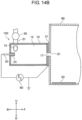
- FIG. 15 illustrates an example of an apparatus for producing reforming liquid in the related art.
- An apparatus for producing reforming liquid as follows is known.
- First electrode 801 and second electrode 802 are disposed in liquid 803 (for example, water).
- a high-voltage pulse from pulse power source 804 is applied between first electrode 801 and second electrode 802, so as to vaporize liquid 803 and generate plasma 805.
- a reformed liquid including, for example, a component such as a hydroxyl radical (OH radical) or hydrogen peroxide, which has an oxidizing force is produced.
- OH radical hydroxyl radical
- hydrogen peroxide which has an oxidizing force
- a high sterilizing action may be applied to germs by mixing a reformed liquid which contains the above component.
- plasma 805 is generated in liquid 803, liquid 803 is coated with plasma 805, and thus a component derived from the liquid is easily generated.
- plasma 805 is generated in the water, and thus an OH radical or hydrogen peroxide is easily generated.
- an apparatus for producing reforming liquid in which a gas introduced from the outside of the apparatus is caused to be interposed between both the electrodes in order to improve the generation efficiency of the plasma with a low applied voltage is known (see PTL 1).
- a pulse voltage is applied between anode electrode 901 and cathode electrode 902 in a state where gas 904 (for example, oxygen) along with treatment target liquid 903 is interposed between anode electrode 901 and cathode electrode 902.
- gas 904 for example, oxygen
- treatment target liquid 903 is interposed between anode electrode 901 and cathode electrode 902.
- PTL 1 discloses a plasma generation apparatus
- PTL 3 discloses a microbubble generating device and water treating apparatus using the same
- PTL 4 discloses a system, method and apparatus for treating liquids with wave energy from an electrical arc.
- the claimed invention is defined in the appended claims. According to an aspect the invention relates to an apparatus for producing reforming liquid according to claim 1.
- the invention relates to a method for producing reforming liquid according to claim 7.
- the plasma is generated in a manner that the liquid is vaporized in the swirling flow and a pulse voltage is applied to the generated gas phase. Since it is not necessary that the liquid is vaporized by applying a voltage, it is possible to generate plasma at small power and it is possible to rapidly reform the liquid with high efficiency. Since the liquid is reformed without introducing an air from an outside, it is possible to suppress forming of nitrous acid which is a harmful substance.
- a gas supply device which includes an oxygen tank, a pump, and the like is required for supplying a gas (for example, oxygen) between the anode electrode and the cathode electrode. Therefore, there is a problem in that the size of the apparatus for producing reforming liquid is increased.
- an air is supplied between the anode electrode and the cathode electrode in order to reduce the size of the gas supply device.
- the oxygen tank is not required, and thus an increase in the size of the apparatus for producing reforming liquid is suppressed.
- nitrogen included in the air is changed to nitrous acid (HNO 2 ) which is harmful to human bodies, by plasma, and nitrous acid is contained in a reformed liquid. Therefore, it may be not possible to supply an air as the gas for generating plasma, in accordance with the use purpose of a reformed liquid.
- an object of the disclosure is to provide an apparatus for producing reforming liquid and a method for producing reforming liquid in which it is possible to rapidly reform a liquid by generating plasma with high efficiency and it is possible to suppress forming of nitrous acid which is a harmful substance.
- FIG. 1 is a side sectional view illustrating a configuration of apparatus for producing reforming liquid 100 according to Exemplary embodiment 1.
- an arrow indicating forward direction F of apparatus for producing reforming liquid 100 and an arrow indicating backward direction B thereof are marked.
- An arrow indicating upward direction U and an arrow indicating downward direction D are marked.
- An arrow indicating rightward direction R when viewed from backward direction B and an arrow indicating leftward direction L when viewed from backward direction B are marked.
- Apparatus for producing reforming liquid 100 forms a reformed component by performing electric discharging in a liquid, and produces a reformed liquid by dispersing the reformed component in the liquid.
- a case where water L1 (see FIG. 4 ) as the liquid is reformed, and thus reformed liquid L2 (not illustrated) which includes a reformed component such as an OH radical or hydrogen peroxide is produced will be described.
- Apparatus for producing reforming liquid 100 includes at least treatment tank 12, first electrode 30, second electrode 31, and power source 60.
- treatment tank 12 an introduced liquid is swirled so as to generate a gas phase in the vicinity of the swirling center of a swirling flow of water L1.
- First electrode 30 has at least a portion which is disposed in treatment tank 12 and comes into contact with water L1 in treatment tank 12.
- Second electrode 31 is disposed to come into contact with water L1 in treatment tank 12.
- Power source 60 applies a voltage between first electrode 30 and second electrode 31 so as to generate plasma in the gas phase.
- Apparatus for producing reforming liquid 100 produces reformed liquid L2 in a manner that the plasma is generated in the gas phase so as to form a reformed component, and the formed reformed component is dissolved and dispersed in water L1.
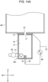
- apparatus for producing reforming liquid 100 includes apparatus main body 10, liquid supplier 50, storage tank 90, and power source 60.
- Apparatus main body 10 includes treatment tank 12, introduction portion 15, discharging portion 17, first electrode 30, and second electrode 31.
- Treatment tank 12 is a component in which a reformed component (for example, OH radical, hydrogen peroxide, or the like) is formed in water L1 introduced into the treatment tank, by plasma.
- the material of treatment tank 12 may be an insulator or a conductor. In a case of the conductor, it is necessary that an insulator is interposed between first electrode 30 and second electrode 31.
- the reformed component is discharged from storage tank 90, the reformed component is dispersed in water L1 and thereby reformed liquid L2 is produced.
- the front sectional shape of an inner wall of treatment tank 12 is circular (see FIG. 3 ).
- Introduction portion 15 is disposed at one end of treatment tank 12. Water L1 is introduced into treatment tank 12 from a tangential direction of the circular sectional shape which is orthogonal to central axis X1 of treatment tank 12, through the introduction portion. Introduction portion 15 communicates with liquid supplier 50 via pipe 51.
- Discharging portion 17 is disposed at the other end of treatment tank 12. Water L1 introduced into treatment tank 12 and the reformed component formed in treatment tank 12 are discharged from treatment tank 12 to storage tank 90 through the discharging portion. In Exemplary embodiment 1, discharging portion 17 is connected to inlet 91 of storage tank 90.
- First electrode 30 is disposed in the one end of treatment tank 12. First electrode 30 is disposed to protrude from the center of the inner wall of the one end of treatment tank 12 toward the inside of treatment tank 12 along a longitudinal direction.
- Second electrode 31 is disposed on an outside of the wall at the other end of treatment tank 12 and is disposed in the vicinity of discharging portion 17.
- First electrode 30 is connected to power source 60 and second electrode 31 is grounded. A pulse voltage which is higher than a voltage of power source 60 is applied to first electrode 30 and second electrode 31. Tungsten is used as an example of the material of first electrode 30.
- Liquid supplier 50 is a pump configured to supply water L1 into treatment tank 12, as an example.
- Liquid supplier 50 is connected to pipe 51.
- One end of pipe 51 is connected to introduction portion 15 as an inner side opening disposed in the vicinity of the inner wall of the one end of treatment tank 12.
- the other end of pipe 51 is connected to a liquid supply source (for example, water tank 80) (not illustrated) or storage tank 90, so as to obtain a form in which stored water of storage tank 90, which includes the reformed liquid can be circulated (see circulation pipe 81 indicated by a one-dot chain line in FIG. 1 ).
- Power source 60 applies a high pulse voltage between first electrode 30 and second electrode 31.
- Power source 60 can alternately apply a positive pulse voltage and a negative pulse voltage, that is, can apply a so-called bipolar pulse voltage.
- Storage tank 90 is a tank in which a reformed component discharged from apparatus for producing reforming liquid 100 is sheared, a micro-bubble or a nano-bubble which encloses the reformed component is generated, and the generated bubbles are diffused in water.
- Storage tank 90 has a sectional area which is greater than a sectional area of an opening of discharging portion 17 in treatment tank 12.
- the reformed component which is discharged from discharging portion 17 into storage tank 90 is sheared in storage tank 90.
- a micro-bubble which encloses the reformed component, or a micro-bubble and a nano-bubble are generated in storage tank 90.
- the generated bubbles are diffused in the water.
- storage tank 90 functions as a micro-bubble generation tank. If storage tank 90 secures an inner diameter or a side which is equal to or longer than twice the dimension of an inner diameter of the opening of discharging portion 17 in treatment tank 12, it is possible to generate a reformed liquid for reliably performing steriliz
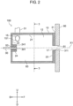
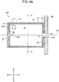
- FIG. 2 is a side sectional view illustrating apparatus main body 10.
- Treatment tank 12 includes first inner wall 21, second inner wall 22, and third inner wall 23.
- First inner wall 21 is a tubular wall portion.
- Second inner wall 22 is provided at the left end portion of first inner wall 21 in FIG. 2 .
- Third inner wall 23 is provided at the right end portion of first inner wall 21 in FIG. 2 .
- Second inner wall 22 and third inner wall 23 are substantially circular when viewed from a side.
- First inner wall 21, second inner wall 22, and third inner wall 23 constitute accommodation space 83 which has a substantially columnar shape, in treatment tank 12.
- Central axis of first inner wall 21, that is, a virtual central axis of accommodation space 83 which has a substantially columnar shape and is configured in treatment tank 12 is assumed to be X1.
- one end portion side of central axis X1" or “one end portion side of first inner wall 21" is assumed to be the left side in FIG. 2 , on which second inner wall 22 is disposed.
- the other end portion side of central axis X1" or “the other end portion side of first inner wall 21” is assumed to be the right side in FIG. 2 , on which third inner wall 23 is disposed.
- Cylindrical electrode support tube 24 which protrudes into accommodation space 83 is provided at the center of second inner wall 22. Electrode support tube 24 is tubular and is extended toward the right. Electrode support tube 24 is disposed so as to cause the central axis of the electrode support tube to coincide with central axis X1 of first inner wall 21.
- First electrode 30 is supported on an inner side of electrode support tube 24, with insulator 53 interposed between the electrode support tube and the first electrode. First electrode 30 has a rod shape. Insulator 53 is disposed around first electrode 30. Therefore, first electrode 30 is disposed so as to cause an axis of the first electrode in the longitudinal direction to coincide with central axis X1 of first inner wall 21.
- An inner side end surface of right end portion 301 of first electrode 30, an inner side end surface of insulator 53, and inner side end surface 241 of electrode support tube 24 are configured so as to be disposed in the substantially same plane.
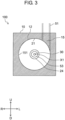
- Introduction portion 15 penetrates apparatus main body 10. One opening end 151 of introduction portion is formed in first inner wall 21. Introduction portion 15 is disposed at a position which is adjacent to second inner wall 22, when viewed from a side. FIG. 3 is a sectional view taken along 3-3 line in FIG. 2 . Introduction portion 15 is disposed on a wall surface of first inner wall 21.
- Discharging portion 17 penetrates the central portion of third inner wall 23. Discharging portion 17 is formed so as to cause the central axis of the discharging portion to coincide with central axis X1 of first inner wall 21.
- Second electrode 31 is a metal member having a plate shape. Opening portion 311 is formed at the central portion of the second electrode. Opening portion 311 is formed so as to have a circular shape and to cause the center of opening portion 311 to coincide with central axis X1 of first inner wall 21.
- second electrode 31 is an electrode which has a plate shape and is disposed so as to surround at least a portion of the entire circumference of central axis X1 on the other end portion side (right side in FIG. 2 ) of first inner wall 21.
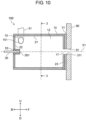
- FIG. 4 is a side sectional view illustrating a state where swirling flow F1 is generated in treatment tank 12 and a pulse voltage is not applied.
- treatment tank 12 includes introduction portion 15 configured to introduce water L1 into treatment tank 12 and discharging portion 17 configured to discharge water L1 from treatment tank 12.
- introduction portion 15 configured to introduce water L1 into treatment tank 12
- discharging portion 17 configured to discharge water L1 from treatment tank 12.
- first electrode 30 is disposed on central axis X1 or on one end portion side (left side in FIG. 4 ) in the vicinity of central axis X1.
- Second electrode 31 is disposed on central axis X1 or one the other end portion side (right side in FIG. 4 ) in the vicinity of central axis X1.
- Introduction portion 15 is disposed on the one end portion side (left side in FIG. 4 ) of central axis X1.
- Discharging portion 17 is disposed on the other end portion side (right side in FIG. 4 ) of central axis X1.
- Swirling flow F1 causes pressure in the vicinity of central axis X1 of first inner wall 21 to be decreased to be equal to or lower than the saturated water vapor pressure.
- water vapor is generated by vaporizing a portion of water L1.
- gas phase G is formed in the vicinity of central axis X1 of first inner wall 21.
- Gas phase G is generated in the vicinity of the swirling center. Specifically, gas phase G is generated from right end portion 301 of first electrode 30 to the vicinity of opening portion 311 of second electrode 31 along central axis X1 of first inner wall 21.
- Gas phase G is swirled by swirling flow F1, in the same direction as that of swirling flow F1.
- Gas phase G which swirls is sheared to form a micro-bubble or a nano-bubble, in a state where resistance of the water in storage tank 90 is applied to the vicinity of discharging portion 17.
- the formed bubbles are diffused in storage tank 90.
- first electrode 30 is disposed to come into contact with gas phase G which is generated in the vicinity of the swirling center of swirling flow F1 of water L1, or is disposed to be positioned in the vicinity of gas phase G.
- FIG. 5 is a sectional view taken along 5-5 line in FIG. 4 .
- clockwise swirling flow F1 in FIG. 5 is generated along first inner wall 21 by using water L1. Since water L1 is swirled in treatment tank 12, pressure in the vicinity of the center of swirling flow F1, that is, in the vicinity of central axis X1 of first inner wall 21 is decreased to be equal to or lower than the saturated water vapor pressure.
- water vapor is generated in the vicinity of central axis X1 of first inner wall 21 by vaporizing a portion of water L1.
- gas phase G is formed.
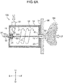
- FIGS. 6A and 6B are side sectional views illustrating a state where swirling flow F1 is generated in treatment tank 12 and a pulse voltage is applied. As illustrated in FIG. 6A , a high pulse voltage is applied between first electrode 30 and second electrode 31 by power source 60, in a state where gas phase G obtained by vaporizing water L1 is generated from the vicinity of first electrode 30 to the vicinity of second electrode 31.
- FIG. 6B is an enlarged view illustrating a state where plasma P is generated in gas phase G.
- first electrode 30 and second electrode 31 cause plasma P to be generated in gas phase G, and causes a radical (OH radical or the like), a compound (hydrogen peroxide or the like), or an ion derived from the water to be generated as the reformed component.
- Gas phase G including the reformed component is swirled by swirling flow F1 around gas phase G, in the same direction as that of swirling flow F1. Since gas phase G including the reformed component is swirled, a portion of the reformed component is dissolved on swirling flow F1 side, and thus the reformed component is dispersed in water L1.
- gas phase G which includes the reformed component in the vicinity of discharging portion 17 is sheared in a state of receiving resistance of water L1 in storage tank 90, and thus bubbles BA which contain the reformed component are generated.
- the reformed liquid is held in storage tank 90, and thus an occurrence of a situation in which an air is mixed in gas phase G in a state of negative pressure is prevented.
- reformed liquid L2 dispersed in water L1 is held in storage tank 90, in a state where the reformed component generated by plasma P is in a bubble state or in a state of being dissolved in water L1.
- apparatus for producing reforming liquid 100 includes treatment tank 12, first electrode 30, second electrode 31, and power source 60.
- treatment tank 12 an introduced liquid is swirled, and thus a gas phase is generated in the vicinity of the swirling center of a swirling flow of water L1.
- First electrode 30 has at least a portion which is disposed in treatment tank 12 and comes into contact with water L1 in treatment tank 12.
- Second electrode 31 is disposed to come into contact with water L1 in treatment tank 12.
- Power source 60 applies a voltage between first electrode 30 and second electrode 31 so as to generate plasma in gas phase G.
- Apparatus for producing reforming liquid 100 produces reformed liquid L2 in a manner that plasma P is generated in gas phase G so as to form a reformed component, and the formed reformed component is dissolved and dispersed in water L1.
- a method for producing reforming liquid includes a process of swirling water L1 introduced into treatment tank 12 so as to generate gas phase G in the vicinity of the swirling center of swirling flow F1 of water L1, in treatment tank 12, and a process of producing reformed liquid L2 in a manner that plasma P is generated in gas phase G by applying a voltage to generated gas phase G, so as to form a reformed component, and the formed reformed component is dissolved and dispersed in water L1.
- plasma P is generated in a manner that water L1 is vaporized in swirling flow F1 and a pulse voltage is applied to generated gas phase G. Therefore, gas phase G has negative pressure in comparison to a gas phase formed by a gas which is vaporized by Joule heat, or a gas introduced from the outside thereof, and plasma P can be generated at a smaller voltage. Accordingly, it is possible to reform water L1 with high efficiency. Further, since the water is not vaporized by Joule heat, the amount of applied energy is reduced. Since a gas is not introduced from the outside thereof, a gas supply device is unnecessary and it is easy to reduce the size of the apparatus for producing reforming liquid.
- a gas phase G formed by a gas which is vaporized by Joule heat or formed by a gas introduced from the outside thereof has difficulty in holding a predetermined shape or being held at a predetermined position by buoyancy.
- a force is applied in a direction in which swirling flow F1 is gathered on central axis X1 by swirling flow F1 around gas phase G.
- gas phase G in the vicinity of right end portion 301 of first electrode 30. Therefore, a change of the amount of a gas formed between first electrode 30 and second electrode 31 over time is small and it is difficult to change power required for plasma P.
- the volume of plasma P is equal to or smaller than the volume of the gas phase which is in the vicinity of the cathode electrode.
- the shape of gas phase G formed by a gas which is vaporized by Joule heat, or a gas introduced from the outside thereof has a bubble shape.
- the volume thereof is equal to or greater than a predetermined value, the shape thereof is broken. Consequently, it is difficult to generate plasma P having a predetermined volume or greater.
- gas phase G in Exemplary embodiment 1 it is easy to increase the volume thereof in a direction of central axis X1 so long as the swirling speed of swirling flow F1 can be secured.
- treatment of water L1 is performed without introducing an air from the outside thereof, it is possible to suppress an occurrence of a situation in which harmful nitrous acid is generated by plasma P which is generated by using a gas phase obtained by introducing a gas such as an air, which includes a nitrogen component. Further, it is possible to produce reformed liquid L2 including bubbles BA which enclose OH radicals, hydrogen peroxide, or the like.
- a position of first electrode 30 is not limited to the structure in Exemplary embodiment 1.
- treatment tank 12 has a simple cylindrical shape.
- treatment tank 12 may have various shapes so long as treatment tank 12 is a tubular treatment tank having a circular sectional shape, and a discharging portion which has a hole shape and is retracted on the central axis of the treatment tank or in the vicinity of the central axis is provided at one end portion of the treatment tank.
- a discharging portion which has a hole shape and is retracted on the central axis of the treatment tank or in the vicinity of the central axis is provided at one end portion of the treatment tank.
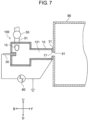
- FIG. 7 even though treatment tank 121 is obtained by combining cylinders which have different radii, the similar effect is obtained.
- FIG. 7 a configuration in which the radius on the introduction portion side is greater than the radius on the discharging portion side is made.
- the treatment tank according to the disclosure has the first inner wall which has a cylindrical shape or a truncated cone shape for swirling water supplied from the introduction portion so as to generate a swirling flow.
- the first electrode is disposed on the central axis of the first inner wall or in the vicinity of the central axis.
- first electrode 30 is a rod electrode, but is not limited thereto so long as the shape thereof causes electrolytic to be concentrated on right end portion 301 of first electrode 30.
- first electrode 32 which has a plate shape and to which a conical shape protruding toward the discharging portion side is attached may be provided.
- first electrode 32A which has a plate shape and has protrusion portion 32B at the central portion may be provided.
- Protrusion portion 32B has a mountain shape and protrudes so as to be bent toward the discharging portion side.
- first electrode 32A which has a plate shape and has protrusion portion 32B having a mountain shape at the central portion, the central portion of the protrusion portion, which is closest to generated plasma P is easily worn.
- an electrode having protrusion portion 32B which is obtained by causing the central portion to protrude into treatment tank 12, and has a mountain shape is preferable in comparison to a simple flat electrode, because of a longer lifespan.
- a rod electrode which is easily sent into treatment tank 12 when the electrode is worn may be provided instead of first electrode 32 having a plate shape.
- first electrode 30 and insulator 53 are attached to second inner wall 22 without using electrode support tube 24 of first electrode 30
- the similar effect is obtained.
- portions other than a connection portion between right end portion 301 of first electrode 30 and power source 60, which is required for generating plasma may be covered with an insulator.
- an example of the material of first electrode 30 is tungsten, but the material thereof is not particularly limited so long as the material is a conductive material.
- a metal material which can exhibit a high sterilization effect by causing the Fenton reaction if the material comes into contact with hydrogen peroxide in water is preferable.
- SUS stainless steel
- copper or copper tungsten may be used.
- second electrode 31 is disposed at discharging portion 17, but in examples not according to the invention the position of the second electrode is not limited so long as at least a portion of the grounded second electrode is disposed in treatment tank 12.
- the position of the second electrode is not limited so long as at least a portion of the grounded second electrode is disposed in treatment tank 12.
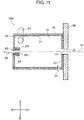
- second electrode 33 having a rod shape is set to be disposed on a side of central axis X1 of first inner wall 21 (for example, as illustrated in FIG. 11 , the second electrode is disposed at a position of penetrating first inner wall 21 from the outside of apparatus main body 10), the similar effect is obtained.
- FIG. 11 shows a disposition place, as illustrated in FIG. 11 , the second electrode is disposed at a position of penetrating first inner wall 21 from the outside of apparatus main body 10
- second electrode 33 having a rod shape may be disposed in storage tank 90 and in the vicinity of inlet 91 of storage tank 90, in addition to treatment tank 12. That is, the second electrode may be disposed on a side of central axis X1 of first inner wall 21 on the other end portion side (right side in FIGS. 11 and 12 ) of first inner wall 21.
- tubular second electrode 34 may be disposed on an inside of first inner wall 21. That is, the second electrode may be a tubular electrode which is disposed to surround at least a portion of the entire circumference of central axis X1 of first inner wall 21 on the other end portion side (right side in FIG. 13 ) of first inner wall 21.
- opening portion 311 is circular, opening portion 311 may be polygonal.
- the second electrode may have a configuration of combining a plurality of metal members which are obtained by division.
- opening portion 311 may have a plate shape or a cylindrical shape which has a round hole. Since resistance of the water is reduced as the distance between gas phase G and the second electrode becomes shorter, and thus it is possible to suppress generation of Joule heat, the second electrode is disposed at discharging portion 17 or in the vicinity of discharging portion 17 such that the distance between gas phase G and the second electrode is short.
- the flow rate of water L1 introduced into treatment tank 12 is set to be a flow rate at which gas phase G is generated in swirling flow F1, in accordance with the shape and the like of treatment tank 12.
- a voltage, a pulse width, a frequency, or the like may be appropriately set to be a value which allows plasma P to be generated in gas phase G generated in swirling flow F1.
- power source 60 may be a high-frequency power source or the like other than a pulse power source so long as the effect of Exemplary embodiment 1 is obtained.
- pH between the electrodes is biased by electrolysis of the water, bipolar application which allows a cathode and an anode to exchange with each other may be performed.
- storage tank 90 is a tank
- the shape of storage tank 90 is not limited thereto so long as the shape can hold water in storage tank 90, in order to shear swirling flow F1.
- storage tank 90 may be a pipe for transporting the reformed liquid.
- apparatus main body 10 may discharge the reformed liquid upwardly and storage tank 90 may be provided on an upper side of apparatus main body 10.
- the material for forming storage tank 90 is not limited so long as water is not permeated.
- plate member 92 which contains copper or iron and allows the high sterilization effect to be exhibited by causing the Fenton reaction with hydrogen peroxide water which is one reformed component can be used as a portion or the entirety of storage tank 90.
- Plate member 92 may be disposed in storage tank 90, as a member which is separate from storage tank 90. In short, if plate member 92 comes into contact with the reformed liquid in storage tank 90, it is possible to exhibit the high sterilization effect by causing the Fenton reaction with hydrogen peroxide water which is one reformed component.
- water L1 is reformed.
- a liquid to be reformed is not limited to the water.
- ethanol may be used as the liquid.
- Exemplary embodiment 1 is described, but Exemplary embodiment 1 described above is just an example for carrying out the disclosure.
- the disclosure is not limited to Exemplary embodiment 1 described above, and Exemplary embodiment 1 described above may be appropriately changed and carried out in a range without departing from the scope of the invention, which is defined in the claims.
- the apparatus for producing reforming liquid and the method for producing reforming liquid in the disclosure can produce a reformed liquid including a reformed component (radical, compound, or the like derived from a liquid), from the liquid by generating plasma in the liquid. Therefore, the apparatus for producing reforming liquid and the method for producing reforming liquid in the disclosure can be used in sterilization, deodorization, and various environmental improvements.
Landscapes
- Engineering & Computer Science (AREA)
- Physics & Mathematics (AREA)
- Plasma & Fusion (AREA)
- Chemical & Material Sciences (AREA)
- Spectroscopy & Molecular Physics (AREA)
- Water Supply & Treatment (AREA)
- Environmental & Geological Engineering (AREA)
- Organic Chemistry (AREA)
- Life Sciences & Earth Sciences (AREA)
- Hydrology & Water Resources (AREA)
- General Chemical & Material Sciences (AREA)
- Electrochemistry (AREA)
- Chemical Kinetics & Catalysis (AREA)
- Health & Medical Sciences (AREA)
- Toxicology (AREA)
- Water Treatment By Electricity Or Magnetism (AREA)
- Physical Or Chemical Processes And Apparatus (AREA)
- Plasma Technology (AREA)
Applications Claiming Priority (3)
| Application Number | Priority Date | Filing Date | Title |
|---|---|---|---|
| JP2016118903 | 2016-06-15 | ||
| JP2017056161A JP6667166B2 (ja) | 2016-06-15 | 2017-03-22 | 改質液生成装置および改質液生成方法 |
| PCT/JP2017/018438 WO2017217170A1 (ja) | 2016-06-15 | 2017-05-17 | 改質液生成装置および改質液生成方法 |
Publications (3)
| Publication Number | Publication Date |
|---|---|
| EP3473601A1 EP3473601A1 (en) | 2019-04-24 |
| EP3473601A4 EP3473601A4 (en) | 2019-05-15 |
| EP3473601B1 true EP3473601B1 (en) | 2023-02-08 |
Family
ID=60890660
Family Applications (1)
| Application Number | Title | Priority Date | Filing Date |
|---|---|---|---|
| EP17813073.8A Active EP3473601B1 (en) | 2016-06-15 | 2017-05-17 | Apparatus for producing reforming liquid and method for producing reforming liquid |
Country Status (4)
| Country | Link |
|---|---|
| US (1) | US10875790B2 (https=) |
| EP (1) | EP3473601B1 (https=) |
| JP (2) | JP6667166B2 (https=) |
| CN (1) | CN107922223B (https=) |
Families Citing this family (10)
| Publication number | Priority date | Publication date | Assignee | Title |
|---|---|---|---|---|
| JP6678336B2 (ja) * | 2017-05-11 | 2020-04-08 | パナソニックIpマネジメント株式会社 | 洗濯機すすぎ水浄化装置及び洗濯装置 |
| JP6653478B2 (ja) * | 2017-05-30 | 2020-02-26 | パナソニックIpマネジメント株式会社 | 脱臭装置 |
| JP6722903B2 (ja) * | 2017-06-01 | 2020-07-15 | パナソニックIpマネジメント株式会社 | 空間改質装置 |
| JP6587159B2 (ja) * | 2017-06-26 | 2019-10-09 | パナソニックIpマネジメント株式会社 | 液体処理装置 |
| JP6854427B2 (ja) | 2018-03-22 | 2021-04-07 | パナソニックIpマネジメント株式会社 | 液体処理装置 |
| JP6990866B2 (ja) * | 2018-05-15 | 2022-01-12 | パナソニックIpマネジメント株式会社 | 液体処理装置 |
| JP7113349B2 (ja) * | 2018-05-15 | 2022-08-05 | パナソニックIpマネジメント株式会社 | 液体処理装置 |
| JP6799824B2 (ja) | 2018-05-16 | 2020-12-16 | パナソニックIpマネジメント株式会社 | 液体処理装置 |
| JP7190696B2 (ja) * | 2019-01-22 | 2022-12-16 | パナソニックIpマネジメント株式会社 | 液体処理方法及び液体処理装置 |
| NL2024131B1 (en) * | 2019-10-31 | 2021-07-19 | Joining Minds Solutions | Waste water cleaning apparatus and system |
Family Cites Families (27)
| Publication number | Priority date | Publication date | Assignee | Title |
|---|---|---|---|---|
| US4772775A (en) | 1987-03-23 | 1988-09-20 | Leach Sam L | Electric arc plasma steam generation |
| JPH01152635U (https=) | 1988-04-12 | 1989-10-20 | ||
| US5464513A (en) | 1994-01-11 | 1995-11-07 | Scientific Utilization, Inc. | Method and apparatus for water decontamination using electrical discharge |
| US6558638B2 (en) * | 1998-03-14 | 2003-05-06 | Splits Technologies Limited | Treatment of liquids |
| US6117401A (en) | 1998-08-04 | 2000-09-12 | Juvan; Christian | Physico-chemical conversion reactor system with a fluid-flow-field constrictor |
| JP4041224B2 (ja) | 1998-09-25 | 2008-01-30 | 正之 佐藤 | 液体処理方法及び液体処理装置 |
| US7857972B2 (en) * | 2003-09-05 | 2010-12-28 | Foret Plasma Labs, Llc | Apparatus for treating liquids with wave energy from an electrical arc |
| JP4357316B2 (ja) * | 2004-02-20 | 2009-11-04 | 株式会社 多自然テクノワークス | 排水処理装置 |
| JP2006130410A (ja) * | 2004-11-05 | 2006-05-25 | Kobe Steel Ltd | 液体処理方法およびその装置 |
| WO2006059808A1 (ja) | 2004-12-03 | 2006-06-08 | Kabushiki Kaisha Toyota Jidoshokki | 液中プラズマ用電極、液中プラズマ発生装置および液中プラズマ発生方法 |
| JP4572388B2 (ja) * | 2005-09-27 | 2010-11-04 | 独立行政法人港湾空港技術研究所 | 攪拌式キャビテーション型化学物質無害化装置、及び攪拌式キャビテーション型化学物質無害化方法 |
| JP5295485B2 (ja) | 2006-02-01 | 2013-09-18 | 株式会社栗田製作所 | 液中プラズマ型被処理液浄化方法及び液中プラズマ型被処理液浄化装置 |
| JP3890076B1 (ja) | 2006-02-03 | 2007-03-07 | 修 松本 | 気泡発生装置 |
| EP2007685B1 (en) * | 2006-04-05 | 2020-06-03 | Foret Plasma Labs, Llc | System, method and apparatus for treating liquids with wave energy from an electrical arc |
| WO2007138773A1 (ja) * | 2006-05-31 | 2007-12-06 | Kabushiki Kaisha Yaskawa Denki | 水処理装置 |
| CN101505859A (zh) * | 2006-09-28 | 2009-08-12 | 仲田涂覆株式会社 | 旋流生成装置、旋流生成方法及气相产生装置、微细气泡产生装置、流体的混合装置、流体喷射喷嘴 |
| FR2922406A1 (fr) | 2007-10-12 | 2009-04-17 | Commissariat Energie Atomique | Dispositif d'injection de charge liquide a melanger/convertir au sein d'un dard plasma ou d'un flux gazeux |
| JP4889124B2 (ja) * | 2007-11-01 | 2012-03-07 | 光弘 渡邉 | 流体処理装置 |
| JP5464692B2 (ja) * | 2009-08-21 | 2014-04-09 | 株式会社安川電機 | 水処理装置 |
| US9023214B2 (en) * | 2010-02-10 | 2015-05-05 | Aic, Llc | Method and apparatus for applying plasma particles to a liquid and use for disinfecting water |
| JP5799503B2 (ja) * | 2010-12-28 | 2015-10-28 | 芝浦メカトロニクス株式会社 | 液中プラズマ発生装置、液中プラズマ処理装置、液中プラズマ発生方法、および液中プラズマ処理方法 |
| JP5099612B2 (ja) | 2011-04-26 | 2012-12-19 | 独立行政法人国立高等専門学校機構 | 液体処理装置 |
| JP2013119043A (ja) * | 2011-12-06 | 2013-06-17 | Panasonic Corp | マイクロバブル発生デバイスとこれを用いた水処理装置 |
| JP6296480B2 (ja) * | 2012-09-26 | 2018-03-20 | 国立大学法人佐賀大学 | 液体処理装置及び液体処理方法 |
| US10793447B2 (en) * | 2014-09-15 | 2020-10-06 | Energy Onvector, LLC | System and method for plasma discharge in liquid |
| JP2016083658A (ja) | 2014-10-24 | 2016-05-19 | パナソニックIpマネジメント株式会社 | プラズマ生成装置 |
| JP6707779B2 (ja) * | 2015-02-13 | 2020-06-10 | 日本スピンドル製造株式会社 | 被処理物質の分散方法並びに分散装置並びにそれによって生成される被処理物質及び分散媒が混合した液体の生成方法 |
-
2017
- 2017-03-22 JP JP2017056161A patent/JP6667166B2/ja active Active
- 2017-05-17 EP EP17813073.8A patent/EP3473601B1/en active Active
- 2017-05-17 US US15/750,685 patent/US10875790B2/en active Active
- 2017-05-17 CN CN201780002805.1A patent/CN107922223B/zh active Active
-
2019
- 2019-12-26 JP JP2019237101A patent/JP6861378B2/ja active Active
Also Published As
| Publication number | Publication date |
|---|---|
| EP3473601A1 (en) | 2019-04-24 |
| JP6667166B2 (ja) | 2020-03-18 |
| EP3473601A4 (en) | 2019-05-15 |
| JP2020049486A (ja) | 2020-04-02 |
| JP2017225965A (ja) | 2017-12-28 |
| CN107922223A (zh) | 2018-04-17 |
| JP6861378B2 (ja) | 2021-04-21 |
| US20180230027A1 (en) | 2018-08-16 |
| CN107922223B (zh) | 2020-10-09 |
| US10875790B2 (en) | 2020-12-29 |
Similar Documents
| Publication | Publication Date | Title |
|---|---|---|
| EP3473601B1 (en) | Apparatus for producing reforming liquid and method for producing reforming liquid | |
| US10610821B2 (en) | Deodorizing apparatus and deodorizing method | |
| JP6678338B2 (ja) | 液体処理装置 | |
| CN108966648B (zh) | 液体处理装置 | |
| EP3647276B1 (en) | Liquid treatment device | |
| WO2017217170A1 (ja) | 改質液生成装置および改質液生成方法 | |
| JP2014210222A (ja) | 液体処理装置 | |
| US20180327284A1 (en) | Washing machine rinse water purification device and washing apparatus | |
| JP2018201768A (ja) | 空間改質装置 | |
| CN109867332B (zh) | 液体处理装置 | |
| US10654730B2 (en) | Liquid processing apparatus | |
| JP2018202282A (ja) | 貯留タンク水処理装置及び貯留式給湯装置 | |
| JP2018196852A (ja) | 液体処理装置 | |
| CN109896580B (zh) | 液体处理装置 | |
| JP7640826B1 (ja) | プラズマ微細気泡発生装置、及びこれを用いた水処理装置、並びに水処理方法 | |
| US10934183B2 (en) | Liquid processing apparatus | |
| JP2019198817A (ja) | 液体処理装置 | |
| JP2020184439A (ja) | 液体処理方法及び液体処理装置 |
Legal Events
| Date | Code | Title | Description |
|---|---|---|---|
| STAA | Information on the status of an ep patent application or granted ep patent |
Free format text: STATUS: THE INTERNATIONAL PUBLICATION HAS BEEN MADE |
|
| PUAI | Public reference made under article 153(3) epc to a published international application that has entered the european phase |
Free format text: ORIGINAL CODE: 0009012 |
|
| STAA | Information on the status of an ep patent application or granted ep patent |
Free format text: STATUS: REQUEST FOR EXAMINATION WAS MADE |
|
| 17P | Request for examination filed |
Effective date: 20180130 |
|
| AK | Designated contracting states |
Kind code of ref document: A1 Designated state(s): AL AT BE BG CH CY CZ DE DK EE ES FI FR GB GR HR HU IE IS IT LI LT LU LV MC MK MT NL NO PL PT RO RS SE SI SK SM TR |
|
| AX | Request for extension of the european patent |
Extension state: BA ME |
|
| A4 | Supplementary search report drawn up and despatched |
Effective date: 20190417 |
|
| RIC1 | Information provided on ipc code assigned before grant |
Ipc: C02F 1/46 20060101AFI20190410BHEP Ipc: H05H 1/24 20060101ALI20190410BHEP Ipc: H05H 1/48 20060101ALI20190410BHEP Ipc: H05H 1/34 20060101ALN20190410BHEP |
|
| DAV | Request for validation of the european patent (deleted) | ||
| DAX | Request for extension of the european patent (deleted) | ||
| STAA | Information on the status of an ep patent application or granted ep patent |
Free format text: STATUS: EXAMINATION IS IN PROGRESS |
|
| 17Q | First examination report despatched |
Effective date: 20210526 |
|
| REG | Reference to a national code |
Ref country code: DE Ref legal event code: R079 Ref document number: 602017065962 Country of ref document: DE Free format text: PREVIOUS MAIN CLASS: C02F0001480000 Ipc: C02F0001460000 |
|
| GRAP | Despatch of communication of intention to grant a patent |
Free format text: ORIGINAL CODE: EPIDOSNIGR1 |
|
| STAA | Information on the status of an ep patent application or granted ep patent |
Free format text: STATUS: GRANT OF PATENT IS INTENDED |
|
| RIC1 | Information provided on ipc code assigned before grant |
Ipc: H05H 1/34 20060101ALN20220831BHEP Ipc: H05H 1/48 20060101ALI20220831BHEP Ipc: H05H 1/24 20060101ALI20220831BHEP Ipc: C02F 1/46 20060101AFI20220831BHEP |
|
| INTG | Intention to grant announced |
Effective date: 20220921 |
|
| GRAS | Grant fee paid |
Free format text: ORIGINAL CODE: EPIDOSNIGR3 |
|
| GRAA | (expected) grant |
Free format text: ORIGINAL CODE: 0009210 |
|
| STAA | Information on the status of an ep patent application or granted ep patent |
Free format text: STATUS: THE PATENT HAS BEEN GRANTED |
|
| AK | Designated contracting states |
Kind code of ref document: B1 Designated state(s): AL AT BE BG CH CY CZ DE DK EE ES FI FR GB GR HR HU IE IS IT LI LT LU LV MC MK MT NL NO PL PT RO RS SE SI SK SM TR |
|
| REG | Reference to a national code |
Ref country code: GB Ref legal event code: FG4D |
|
| REG | Reference to a national code |
Ref country code: CH Ref legal event code: EP Ref country code: AT Ref legal event code: REF Ref document number: 1547444 Country of ref document: AT Kind code of ref document: T Effective date: 20230215 |
|
| REG | Reference to a national code |
Ref country code: IE Ref legal event code: FG4D |
|
| REG | Reference to a national code |
Ref country code: DE Ref legal event code: R096 Ref document number: 602017065962 Country of ref document: DE |
|
| REG | Reference to a national code |
Ref country code: LT Ref legal event code: MG9D |
|
| REG | Reference to a national code |
Ref country code: NL Ref legal event code: MP Effective date: 20230208 |
|
| REG | Reference to a national code |
Ref country code: AT Ref legal event code: MK05 Ref document number: 1547444 Country of ref document: AT Kind code of ref document: T Effective date: 20230208 |
|
| PG25 | Lapsed in a contracting state [announced via postgrant information from national office to epo] |
Ref country code: RS Free format text: LAPSE BECAUSE OF FAILURE TO SUBMIT A TRANSLATION OF THE DESCRIPTION OR TO PAY THE FEE WITHIN THE PRESCRIBED TIME-LIMIT Effective date: 20230208 Ref country code: PT Free format text: LAPSE BECAUSE OF FAILURE TO SUBMIT A TRANSLATION OF THE DESCRIPTION OR TO PAY THE FEE WITHIN THE PRESCRIBED TIME-LIMIT Effective date: 20230609 Ref country code: NO Free format text: LAPSE BECAUSE OF FAILURE TO SUBMIT A TRANSLATION OF THE DESCRIPTION OR TO PAY THE FEE WITHIN THE PRESCRIBED TIME-LIMIT Effective date: 20230508 Ref country code: NL Free format text: LAPSE BECAUSE OF FAILURE TO SUBMIT A TRANSLATION OF THE DESCRIPTION OR TO PAY THE FEE WITHIN THE PRESCRIBED TIME-LIMIT Effective date: 20230208 Ref country code: LV Free format text: LAPSE BECAUSE OF FAILURE TO SUBMIT A TRANSLATION OF THE DESCRIPTION OR TO PAY THE FEE WITHIN THE PRESCRIBED TIME-LIMIT Effective date: 20230208 Ref country code: LT Free format text: LAPSE BECAUSE OF FAILURE TO SUBMIT A TRANSLATION OF THE DESCRIPTION OR TO PAY THE FEE WITHIN THE PRESCRIBED TIME-LIMIT Effective date: 20230208 Ref country code: HR Free format text: LAPSE BECAUSE OF FAILURE TO SUBMIT A TRANSLATION OF THE DESCRIPTION OR TO PAY THE FEE WITHIN THE PRESCRIBED TIME-LIMIT Effective date: 20230208 Ref country code: ES Free format text: LAPSE BECAUSE OF FAILURE TO SUBMIT A TRANSLATION OF THE DESCRIPTION OR TO PAY THE FEE WITHIN THE PRESCRIBED TIME-LIMIT Effective date: 20230208 Ref country code: AT Free format text: LAPSE BECAUSE OF FAILURE TO SUBMIT A TRANSLATION OF THE DESCRIPTION OR TO PAY THE FEE WITHIN THE PRESCRIBED TIME-LIMIT Effective date: 20230208 |
|
| PG25 | Lapsed in a contracting state [announced via postgrant information from national office to epo] |
Ref country code: SE Free format text: LAPSE BECAUSE OF FAILURE TO SUBMIT A TRANSLATION OF THE DESCRIPTION OR TO PAY THE FEE WITHIN THE PRESCRIBED TIME-LIMIT Effective date: 20230208 Ref country code: PL Free format text: LAPSE BECAUSE OF FAILURE TO SUBMIT A TRANSLATION OF THE DESCRIPTION OR TO PAY THE FEE WITHIN THE PRESCRIBED TIME-LIMIT Effective date: 20230208 Ref country code: IS Free format text: LAPSE BECAUSE OF FAILURE TO SUBMIT A TRANSLATION OF THE DESCRIPTION OR TO PAY THE FEE WITHIN THE PRESCRIBED TIME-LIMIT Effective date: 20230608 Ref country code: GR Free format text: LAPSE BECAUSE OF FAILURE TO SUBMIT A TRANSLATION OF THE DESCRIPTION OR TO PAY THE FEE WITHIN THE PRESCRIBED TIME-LIMIT Effective date: 20230509 Ref country code: FI Free format text: LAPSE BECAUSE OF FAILURE TO SUBMIT A TRANSLATION OF THE DESCRIPTION OR TO PAY THE FEE WITHIN THE PRESCRIBED TIME-LIMIT Effective date: 20230208 |
|
| PG25 | Lapsed in a contracting state [announced via postgrant information from national office to epo] |
Ref country code: SM Free format text: LAPSE BECAUSE OF FAILURE TO SUBMIT A TRANSLATION OF THE DESCRIPTION OR TO PAY THE FEE WITHIN THE PRESCRIBED TIME-LIMIT Effective date: 20230208 Ref country code: RO Free format text: LAPSE BECAUSE OF FAILURE TO SUBMIT A TRANSLATION OF THE DESCRIPTION OR TO PAY THE FEE WITHIN THE PRESCRIBED TIME-LIMIT Effective date: 20230208 Ref country code: EE Free format text: LAPSE BECAUSE OF FAILURE TO SUBMIT A TRANSLATION OF THE DESCRIPTION OR TO PAY THE FEE WITHIN THE PRESCRIBED TIME-LIMIT Effective date: 20230208 Ref country code: DK Free format text: LAPSE BECAUSE OF FAILURE TO SUBMIT A TRANSLATION OF THE DESCRIPTION OR TO PAY THE FEE WITHIN THE PRESCRIBED TIME-LIMIT Effective date: 20230208 Ref country code: CZ Free format text: LAPSE BECAUSE OF FAILURE TO SUBMIT A TRANSLATION OF THE DESCRIPTION OR TO PAY THE FEE WITHIN THE PRESCRIBED TIME-LIMIT Effective date: 20230208 |
|
| REG | Reference to a national code |
Ref country code: DE Ref legal event code: R097 Ref document number: 602017065962 Country of ref document: DE |
|
| PG25 | Lapsed in a contracting state [announced via postgrant information from national office to epo] |
Ref country code: SK Free format text: LAPSE BECAUSE OF FAILURE TO SUBMIT A TRANSLATION OF THE DESCRIPTION OR TO PAY THE FEE WITHIN THE PRESCRIBED TIME-LIMIT Effective date: 20230208 |
|
| PLBE | No opposition filed within time limit |
Free format text: ORIGINAL CODE: 0009261 |
|
| STAA | Information on the status of an ep patent application or granted ep patent |
Free format text: STATUS: NO OPPOSITION FILED WITHIN TIME LIMIT |
|
| REG | Reference to a national code |
Ref country code: CH Ref legal event code: PL |
|
| 26N | No opposition filed |
Effective date: 20231109 |
|
| PG25 | Lapsed in a contracting state [announced via postgrant information from national office to epo] |
Ref country code: MC Free format text: LAPSE BECAUSE OF FAILURE TO SUBMIT A TRANSLATION OF THE DESCRIPTION OR TO PAY THE FEE WITHIN THE PRESCRIBED TIME-LIMIT Effective date: 20230208 |
|
| GBPC | Gb: european patent ceased through non-payment of renewal fee |
Effective date: 20230517 |
|
| REG | Reference to a national code |
Ref country code: BE Ref legal event code: MM Effective date: 20230531 |
|
| PG25 | Lapsed in a contracting state [announced via postgrant information from national office to epo] |
Ref country code: SI Free format text: LAPSE BECAUSE OF FAILURE TO SUBMIT A TRANSLATION OF THE DESCRIPTION OR TO PAY THE FEE WITHIN THE PRESCRIBED TIME-LIMIT Effective date: 20230208 Ref country code: MC Free format text: LAPSE BECAUSE OF FAILURE TO SUBMIT A TRANSLATION OF THE DESCRIPTION OR TO PAY THE FEE WITHIN THE PRESCRIBED TIME-LIMIT Effective date: 20230208 Ref country code: LU Free format text: LAPSE BECAUSE OF NON-PAYMENT OF DUE FEES Effective date: 20230517 Ref country code: LI Free format text: LAPSE BECAUSE OF NON-PAYMENT OF DUE FEES Effective date: 20230531 Ref country code: CH Free format text: LAPSE BECAUSE OF NON-PAYMENT OF DUE FEES Effective date: 20230531 |
|
| REG | Reference to a national code |
Ref country code: IE Ref legal event code: MM4A |
|
| PG25 | Lapsed in a contracting state [announced via postgrant information from national office to epo] |
Ref country code: IE Free format text: LAPSE BECAUSE OF NON-PAYMENT OF DUE FEES Effective date: 20230517 |
|
| PG25 | Lapsed in a contracting state [announced via postgrant information from national office to epo] |
Ref country code: IE Free format text: LAPSE BECAUSE OF NON-PAYMENT OF DUE FEES Effective date: 20230517 Ref country code: GB Free format text: LAPSE BECAUSE OF NON-PAYMENT OF DUE FEES Effective date: 20230517 |
|
| PG25 | Lapsed in a contracting state [announced via postgrant information from national office to epo] |
Ref country code: IT Free format text: LAPSE BECAUSE OF FAILURE TO SUBMIT A TRANSLATION OF THE DESCRIPTION OR TO PAY THE FEE WITHIN THE PRESCRIBED TIME-LIMIT Effective date: 20230208 Ref country code: FR Free format text: LAPSE BECAUSE OF NON-PAYMENT OF DUE FEES Effective date: 20230531 Ref country code: BE Free format text: LAPSE BECAUSE OF NON-PAYMENT OF DUE FEES Effective date: 20230531 |
|
| PG25 | Lapsed in a contracting state [announced via postgrant information from national office to epo] |
Ref country code: BG Free format text: LAPSE BECAUSE OF FAILURE TO SUBMIT A TRANSLATION OF THE DESCRIPTION OR TO PAY THE FEE WITHIN THE PRESCRIBED TIME-LIMIT Effective date: 20230208 |
|
| PG25 | Lapsed in a contracting state [announced via postgrant information from national office to epo] |
Ref country code: BG Free format text: LAPSE BECAUSE OF FAILURE TO SUBMIT A TRANSLATION OF THE DESCRIPTION OR TO PAY THE FEE WITHIN THE PRESCRIBED TIME-LIMIT Effective date: 20230208 |
|
| PGFP | Annual fee paid to national office [announced via postgrant information from national office to epo] |
Ref country code: DE Payment date: 20250521 Year of fee payment: 9 |
|
| PG25 | Lapsed in a contracting state [announced via postgrant information from national office to epo] |
Ref country code: CY Free format text: LAPSE BECAUSE OF FAILURE TO SUBMIT A TRANSLATION OF THE DESCRIPTION OR TO PAY THE FEE WITHIN THE PRESCRIBED TIME-LIMIT; INVALID AB INITIO Effective date: 20170517 |
|
| PG25 | Lapsed in a contracting state [announced via postgrant information from national office to epo] |
Ref country code: HU Free format text: LAPSE BECAUSE OF FAILURE TO SUBMIT A TRANSLATION OF THE DESCRIPTION OR TO PAY THE FEE WITHIN THE PRESCRIBED TIME-LIMIT; INVALID AB INITIO Effective date: 20170517 |
|
| PG25 | Lapsed in a contracting state [announced via postgrant information from national office to epo] |
Ref country code: TR Free format text: LAPSE BECAUSE OF FAILURE TO SUBMIT A TRANSLATION OF THE DESCRIPTION OR TO PAY THE FEE WITHIN THE PRESCRIBED TIME-LIMIT Effective date: 20230208 |