EP3472386B1 - Anordnung zum umstellen einer zungenschiene - Google Patents
Anordnung zum umstellen einer zungenschiene Download PDFInfo
- Publication number
- EP3472386B1 EP3472386B1 EP17729457.6A EP17729457A EP3472386B1 EP 3472386 B1 EP3472386 B1 EP 3472386B1 EP 17729457 A EP17729457 A EP 17729457A EP 3472386 B1 EP3472386 B1 EP 3472386B1
- Authority
- EP
- European Patent Office
- Prior art keywords
- base plate
- holder
- arrangement according
- rail
- longitudinal direction
- Prior art date
- Legal status (The legal status is an assumption and is not a legal conclusion. Google has not performed a legal analysis and makes no representation as to the accuracy of the status listed.)
- Active
Links
Images

Classifications
-
- E—FIXED CONSTRUCTIONS
- E01—CONSTRUCTION OF ROADS, RAILWAYS, OR BRIDGES
- E01B—PERMANENT WAY; PERMANENT-WAY TOOLS; MACHINES FOR MAKING RAILWAYS OF ALL KINDS
- E01B7/00—Switches; Crossings
- E01B7/02—Tongues; Associated constructions
- E01B7/08—Other constructions of tongues, e.g. tilting about an axis parallel to the rail, movable tongue blocks or rails
-
- E—FIXED CONSTRUCTIONS
- E01—CONSTRUCTION OF ROADS, RAILWAYS, OR BRIDGES
- E01B—PERMANENT WAY; PERMANENT-WAY TOOLS; MACHINES FOR MAKING RAILWAYS OF ALL KINDS
- E01B7/00—Switches; Crossings
- E01B7/02—Tongues; Associated constructions
-
- E—FIXED CONSTRUCTIONS
- E01—CONSTRUCTION OF ROADS, RAILWAYS, OR BRIDGES
- E01B—PERMANENT WAY; PERMANENT-WAY TOOLS; MACHINES FOR MAKING RAILWAYS OF ALL KINDS
- E01B7/00—Switches; Crossings
- E01B7/22—Special sleepers for switches or crossings; Fastening means therefor
Definitions
- the invention relates to an arrangement for converting a tongue rail to a stock rail comprising a holder with at least one roller element which is a support for the tongue rail, the holder being adjustable relative to the stock rail.
- a corresponding arrangement is the DE 10 2004 013 347 A1 refer to.
- a holder that accommodates at least one roller element can be connected to an insert which has a plurality of bores in order to position the holder containing the roller element at the desired distance from the stock rail.
- a support roller holder is connected via a toothed rail running in the direction of the tongue rail with a clamping device that can be fastened to the rail foot of the stock rail.
- a switch blade lifting and rolling device offers the possibility that a roller carrier can be adjusted in height over an inclined plane.
- the EP 1 627 954 A2 provides a roller device for supporting a tongue rail, in which a frame carrying the rollers is fixed by means of a toothed strip which enables the frame to be horizontally adjusted in a locked position.
- Subject of DE 10 2004 004 784 B4 is a device for moving a tongue rail.
- the device has two rollers which extend from a base body which is formed integrally with a cover which extends between the rollers.
- the present invention is based on the object of developing an arrangement of the type described above in such a way that, with structurally simple measures, it is possible to adjust the roller elements both horizontally and vertically to the stock rail. Adjustment should be possible without problems, but at the same time it should be ensured that uncontrolled rotation of the holder does not occur.
- the invention essentially provides that the holder is connected to a base plate that has a wedge-shaped geometry or a wedge-shaped area in which the holder is supported on the base plate, that the base plate is transverse to the longitudinal direction of the jaws - or tongue rail is guided adjustable in the direction running, and that the holder is adjustable relative to the base plate stepwise transversely to the longitudinal direction of the stock or tongue rail.
- the holder is based on a base plate which enables the holder to be guided transversely to the longitudinal direction of the tongue rail. This enables the holder to be easily positioned and aligned with respect to the stock rail, since it is connected to the base plate in a form-fitting manner via a latch. At the same time, this prevents twisting or uncontrolled adjustment of the holder relative to the base plate.
- the base plate is connected to a support such as a ribbed plate and is guided transversely or perpendicularly to the longitudinal direction of the tongue rail.
- a first guide element running transversely or perpendicular to the longitudinal direction of the tongue rail can start from the support and interact with a second guide element extending from the base plate for guided adjustment of the base plate transversely to the longitudinal direction of the tongue rail.
- first guide element is preferably a single bar and the second guide element is a groove-like longitudinal recess running on the bottom side in the base plate, or vice versa.
- a recess running transversely or perpendicular to the longitudinal direction of the tongue rail can be formed in the support as the first guide element, the width of which corresponds to that of the base plate, so that it is received by the support in a displaceable manner transversely or perpendicularly to the longitudinal direction of the tongue rail.
- At least one web-shaped or strip-shaped projection extends from the bottom surface of the base plate facing the support, the width of which is adapted to a recess present in the support, so that the base plate can also be guided transversely or perpendicular to the longitudinal direction of the tongue rail stands.
- the first guide element like the bar or recess or recess, is penetrated by bores into which a bolt element engages, via which the holder can be subjected to force in the direction of the base.
- an elongated hole runs transversely or perpendicularly to the longitudinal direction of the tongue rail and is penetrated by the bolt element.
- a roller element is mounted in the respective end area of the holder, that is to say in front of and behind the elongated hole.
- the holder and the base plate In order to enable the latched or stepped adjustment of the holder and the base plate, provision is made for the holder and the base plate to have a toothed grid or an equivalent structure in the areas lying on top of one another.
- the base plate is non-positively connected to the base with a single bolt element which penetrates the holder and the base plate and is supported on the holder.
- the base plate and / or the holder are made of plastic, in particular of polyamide with e.g. a glass fiber content of e.g. 15-30% by weight.
- the base plate with the holder run between sections of a sliding chair that is attached to the support such as the rib plate.
- switches are important transition points for freight or passenger traffic.
- the function of the switch is to carry and guide the train along a given route. This includes various branches and cuts.
- the formation and dissolving, crossing and overtaking of trains are among the main tasks of a switch.
- a tongue roller device is proposed with which the possibility is created to adjust the rollers supporting a tongue rail to a stock rail both horizontally and vertically, in addition to problem-free assembly and maintenance, readjustment in both the horizontal and vertical directions with little effort is made possible. At the same time it is ensured that a clear positioning of the rollers supporting the tongue rail is guaranteed.
- FIG. 1 shows a section of a rail fastening point of a switch device of a switch in which a switch rail 14 is to be adjusted to a stock rail 12 in order to guide a vehicle passing through the switch in a desired direction depending on the position of the switch rail 14.
- the detail shows an intermediate plate 16 resting on a threshold or concrete slab, for example ( Fig. 2 ), which can be rigid or elastic and on which a ribbed plate 18 is supported, on which the stock rail 12 is fixed in the usual way.
- a tension clamp 20 on the one hand and tension springs 22, 24 on the other hand are used.
- the tension springs 22, 24 are tensioned between counter bearings 32, 34 extending from the ribbed plate 18 on the one hand and sections of a slide chair 36 on the other hand, which according to the drawing has a U-shape and in the area of its transverse leg 38 on a section 28 of the rail foot 30 of Stock rail 12 rests.
- the tension clamp 20 is supported on the opposite section 26. In this respect, however, reference is made to well-known constructions.
- an intermediate layer 40 z. b. made of EVA (ethylene vinyl acetate).
- An intermediate layer 47, 49 can likewise be provided between the longitudinal legs 42, 44 of the U-shaped slide chair 36 and the rib plate 18.
- the stock rail 12 is held down on the one hand by the tension clamp 20 and on the other hand by the transverse leg 38 of the slide chair 36.
- the tension clamp 20 is penetrated by a screw 46 which is connected to the support of the switch.
- the roller device 10 When the tongue rail 14 is moved, it is lifted with the aid of a roller device 10 which extends between the longitudinal legs 42, 44 of the slide chair 36 and is connected to the rib plate 18.
- the roller device 10 consists of a wedge-shaped base plate 48 and a carrier 54 which supports rollers 50, 52 and which likewise has a wedge shape.
- the base plate 48 and the carrier can consist of metal, in particular nodular cast iron.
- the base plate 48 and / or the holder 54 in particular both the base plate 48 and the holder from plastic, in particular from polyamide, which is e.g. may contain a proportion of glass fiber between 15% by weight and 30% by weight.
- the areas lying on top of one another i.e. on the one hand the surface 56, which runs inclined to the underside of the base plate 48, and on the other hand the facing surface 58 of the holder 54, have a structure that enables gradual adjustment, which in the exemplary embodiment is a toothed grid 60, 62 are formed.
- Other structures that allow gradual adjustment are also possible.
- Due to the wedge shape of the base plate 48 a vertical adjustment of the holder 54, also known as a roller cassette, takes place when it is adjusted in the longitudinal direction of the base plate 48, i.e. a vertical adjustment of the rollers 50, 52. At the same time, the horizontal distance between the rollers 50, 52 and the stock rail 12 changed.
- the holder 54 Since the rollers 50, 52 should always run horizontally regardless of the position of the holder 54 in relation to the base plate 48 in their contact areas running with the tongue rail 14, the holder 54 has a geometry corresponding to the wedge shape of the base plate 48 or the axes 78, 80 are positioned in the holder 54 in such a way that the desired horizontal orientation is always present.
- the teeth of the grids 60, 62 have a distance a of 3 mm.
- the angle between the underside of the base plate 48 and its upper side (surface 56) should be in the range of approximately 6 °, so that the holder 54 and thus the rollers 50, 52 can be raised or lowered by approximately + from tooth to tooth / - 0.3 mm results.
- Other dimensions are of course also possible.
- the base plate 48 In order to ensure that the roller device 10 does not rotate in an uncontrolled manner without having to take structurally complex measures, an alternative further development provides for the base plate 48 to have a longitudinal groove 64 on the bottom side that runs in its longitudinal direction and is preferably square in section, which geometrically a bar 66 to be designated as a roller base is adapted, which extends from the rib plate 18 and runs in the longitudinal direction thereof. This ensures that the base plate 48 and thus the roller device 10 can essentially only be adjusted in its longitudinal direction, that is to say transversely or perpendicular to the longitudinal direction of the stock rail 12.
- the bar 66 has bores, some of which are identified by way of example with the reference numerals 68, 70.
- a fastening screw 72 can be screwed into one of the bores and passes through both the holder 54 and the base plate 48, so that when the screw 72 is tightened, the roller device 10 frictionally engages with the ribbed plate 18 and the base plate 48 and the holder 54 with one another both non-positively are also positively connected.
- the fastening screw penetrates elongated holes 74, 76 of the base plate 48 and the bracket 54 Position of the roller device 10 in relation to the stock rail 12 as a function of the bore can be set, in which the fastening screw 72 is screwed into the bar 66. Additional fine adjustment takes place via the elongated holes 74, 76.
- rollers 50, 52 designed as hollow cylinders are penetrated by axles 78, 80 which in turn are mounted in legs of the roller cassette or holder 54, which are not identified in detail.
- axles 78, 80 which in turn are mounted in legs of the roller cassette or holder 54, which are not identified in detail.
- the figures are self-explanatory as mentioned.
- the bar 66 and the groove 64 thus form a guide for the roller device 10 so that it can be adjusted essentially exclusively transversely or perpendicularly to the longitudinal direction of the stock rail 12.
- a single fastening screw is thus sufficient to fix the roller device 10 securely and clearly to the ribbed plate 18 and thus to the stock rail 12.
- rollers 50, 52 extend from the holder 54 and are rotatably mounted in the respective end region of the holder 54.
- the elongated hole 76 the longitudinal direction of which runs transversely or perpendicular to the axes 78, 80, runs between the rollers 50, 52.
- roller device 10 When assembling the roller device 10, with the aid of a feeler gauge, a distance from the lower edge of the tongue foot to the roller 50, 52 of e.g. about 1 mm can be adjusted. If it turns out that the rollers 50, 52 are too low or too high, the inclined plane of the surface 56 and the toothed grids 60, 62 can lower or raise the rollers 50, 52 with simultaneous horizontal adjustment. After the desired dimension has been set, the roller device 10 is tightened by means of the fastening screw 72 and e.g. fixed by a lock washer.
- a longitudinal recess 67 is provided, the width of which corresponds to the width of the base plate 48, so that guidance takes place transversely or perpendicular to the tongue rail longitudinal axis 14 in accordance with the guidance with the strip 66.
- a guide can also be implemented in that at least one strip-shaped projection extends from the underside of the base plate 48 and extends in the longitudinal direction of the base plate 48.
- a depression is formed in the rib plate 18 corresponding to the width of the projection, so that the desired guidance is also ensured transversely or perpendicularly to the longitudinal axis of the tongue rail. Otherwise, the structural features of the rail fastening point are the same as those associated with the Fig. 1-4 have been explained.
Landscapes
- Engineering & Computer Science (AREA)
- Mechanical Engineering (AREA)
- Architecture (AREA)
- Civil Engineering (AREA)
- Structural Engineering (AREA)
- Railway Tracks (AREA)
- Escalators And Moving Walkways (AREA)
- Support Devices For Sliding Doors (AREA)
- Tumbler Switches (AREA)
- Machines For Laying And Maintaining Railways (AREA)
- Push-Button Switches (AREA)
- Switches That Are Operated By Magnetic Or Electric Fields (AREA)
- Knitting Machines (AREA)
- Portable Nailing Machines And Staplers (AREA)
- Train Traffic Observation, Control, And Security (AREA)
Description
- Die Erfindung bezieht sich auf eine Anordnung zum Umstellen einer Zungenschiene zu einer Backenschiene umfassend eine Halterung mit zumindest einem Rollenelement, das Auflage für die Zungenschiene ist, wobei die Halterung relativ zu der Backenschiene verstellbar ist.
- Eine entsprechende Anordnung ist der
DE 10 2004 013 347 A1 zu entnehmen. Hierzu ist eine zumindest ein Rollenelement aufnehmende Halterung mit einem Einsatz verbindbar, die mehrere Bohrungen aufweist, um die das Rollenelement aufweisende Halterung im gewünschten Abstand zur Backenschiene zu positionieren. - Bei einer Rollvorrichtung zur Abstützung einer Weichenzunge nach der
DE 10 2005 032 417 B4 ist ein Stützrollenhalter über eine in Richtung auf die Zungenschiene verlaufende Zahnschiene mit einer am Schienenfuß der Backenschiene befestigbaren Klemmvorrichtung verbunden. - Eine Weichenzungenhebe- und Rollvorrichtung nach der
DE 10 2008 052 152 A1 bietet die Möglichkeit, dass ein Rollenträger über eine schiefe Ebene in seiner Höhe verstellt werden kann. - Die
EP 1 627 954 A2 sieht eine Rollenvorrichtung zum Abstützen einer Zungenschiene vor, bei der ein die Rollen tragender Rahmen über eine Zahnleiste fixiert ist, die ein gerastetes horizontales Verstellen des Rahmens ermöglicht. - Gegenstand der
DE 10 2004 004 784 B4 ist eine Vorrichtung zum Verschieben einer Zungenschiene. Die Vorrichtung weist zwei Rollen auf, die von einem Grundkörper ausgehen, der integral mit einer Abdeckung ausgebildet ist, die zwischen den Rollen verläuft. - Der vorliegenden Erfindung liegt die Aufgabe zugrunde, eine Anordnung zuvor beschriebener Art so weiterzubilden, dass mit konstruktiv einfachen Maßnahmen ein Verstellen der Rollenelemente sowohl horizontal als auch vertikal zur Backenschiene ermöglicht wird. Dabei soll ein problemloses Verstellen möglich, gleichzeitig jedoch sichergestellt sein, dass ein unkontrolliertes Verdrehen der Halterung unterbleibt.
- Zur Lösung der Aufgabe sieht die Erfindung im Wesentlichen vor, dass die Halterung mit einer Grundplatte verbunden ist, die eine keilförmige Geometrie oder einen keilförmig ausgebildeten Bereich aufweist, in dem die Halterung auf der Grundplatte abgestützt ist, dass die Grundplatte in quer zur Längsrichtung der Backen- bzw. Zungenschiene verlaufender Richtung geführt verstellbar ist, und dass die Halterung relativ zu der Grundplatte stufenweise quer zur Längsrichtung der Backen- bzw. Zungenschiene verstellbar ist.
- Erfindungsgemäß geht die Halterung von einer Grundplatte aus, die eine Führung der Halterung quer zur Längsrichtung der Zungenschiene ermöglicht. Somit ist ein einfaches Positionieren und Ausrichten der Halterung zu der Backenschiene möglich, da diese formschlüssig mit der Grundplatte über eine Verrastung verbunden ist. Hierdurch wird gleichzeitig ein Verdrehen oder unkontrolliertes Verstellen der Halterung zu der Grundplatte verhindert.
- Durch die Keilgeometrie der Grundplatte bzw. des die Halterung aufnehmenden Bereichs der Grundplatte ist ein problemloses horizontales und vertikales Verstellen der Halterung zu der Backenschiene und somit des zumindest einen Rollenelements gewährleistet.
- Um das Führen der Grundplatte und damit der Anordnung selbst mit konstruktiv einfachen Maßnahmen zu ermöglichen, sieht eine optionale Weiterbildung vor, dass die Grundplatte mit einer Abstützung wie Rippenplatte verbunden ist und quer bzw. senkrecht zur Zungenschienenlängsrichtung geführt ist.
- Nach einer ersten Alternativen kann hierzu von der Abstützung ein quer bzw. senkrecht zur Zungenschienenlängsrichtung verlaufendes erstes Führungselement ausgehen, das mit einem von der Grundplatte ausgehenden zweiten Führungselement zum geführten Verstellen der Grundplatte quer zur Längsrichtung der Zungenschiene wechselwirkt.
- Dabei ist insbesondere vorgesehen, dass das erste Führungselement vorzugsweise eine einzige Leiste und das zweite Führungselement eine bodenseitig in der Grundplatte verlaufende nutartige Längsaussparung ist oder umgekehrt.
- Alternativ kann in der Abstützung eine quer bzw. senkrecht zur Zungenschienenlängsrichtung verlaufende Vertiefung als erstes Führungselement ausgebildet sein, deren Breite der der Grundplatte entspricht, so dass diese quer bzw. senkrecht zur Zungenschienenlängsrichtung geführt verschiebbar von der Abstützung aufgenommen ist.
- Auch besteht die Möglichkeit, dass von der der Abstützung zugewandten Bodenfläche der Grundplatte zumindest ein steg- bzw. leistenförmiger Vorsprung ausgeht, dessen Breitenerstreckung einer in der Abstützung vorhandenen Vertiefung angepasst ist, so dass gleichfalls eine Führung der Grundplatte quer bzw. senkrecht zur Zungenschienenlängsrichtung zur Verfügung steht.
- Bevorzugterweise ist vorgesehen, dass das erste Führungselement wie die Leiste bzw. Vertiefung oder Aussparung von Bohrungen durchsetzt ist, in die ein Bolzelement eingreift, über das die Halterung in Richtung der Unterlage kraftbeaufschlagbar ist.
- Um ein kontinuierliches horizontales Verstellen zu ermöglichen, kann vorgesehen werden, dass in der Halterung und/oder der Grundplatte, vorzugsweise sowohl in der Halterung als auch der Grundplatte, ein quer bzw. senkrecht zur Zungenschienenlängsrichtung verlaufendes und von dem Bolzelement durchsetztes Langloch verläuft.
- In Weiterbildung ist vorgesehen, dass im jeweiligen Endbereich der Halterung jeweils ein Rollenelement gelagert ist, das heißt vor und hinter dem Langloch.
- Um das gerastete bzw. gestufte Verstellen von Halterung und Grundplatte zu ermöglichen, ist vorgesehen, dass die Halterung und die Grundplatte in den aufeinanderliegenden Bereichen bereichsweise eine Zahnrasterung oder eine gleichwirkende Struktur aufweisen.
- Um eine problemlose Montage bei gleichzeitiger sicherer Befestigung zu gewährleisten, ist vorgesehen, dass die Grundplatte mit einem einzigen die Halterung und die Grundplatte durchsetzenden und sich an der Haltung abstützenden Bolzelement kraftschlüssig mit der Unterlage verbunden ist.
- Ferner kann vorgesehen werden, , dass die Grundplatte und/oder die Halterung, insbesondere sowohl die Grundplatte als auch die Halterung aus Kunststoff, insbesondere aus Polyamid mit z.B. einem Glasfaseranteil von z.B. 15 30 Gew.-% besteht.
- Insbesondere ist vorgesehen, dass die Grundplatte mit der Halterung zwischen Abschnitten eines Gleitstuhls verlaufen, die auf der Abstützung wie der Rippenplatte befestigt ist.
- Weitere Einzelheiten, Vorteile und Merkmale der Erfindung ergeben sich aus der nachfolgenden Beschreibung eines der Zeichnung zu entnehmenden bevorzugten Ausführungsbeispiels.
- Es zeigen:
- Fig. 1
- eine perspektivische Darstellung eines Schienenbefestigungselementes im Bereich einer Zungenvorrichtung einer Weiche,
- Fig. 2
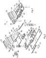
- Elemente des Ausschnitts, gemäß
Fig. 1 in auseinandergezogener Darstellung, - Fig. 3
- eine Rolleneinrichtung,
- Fig. 4
- die Rolleneinrichtung gemäß
Fig. 3 in auseinandergezogener Darstellung und - Fig. 5
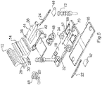
- eine der
Fig. 2 entsprechende Darstellung mit einer alternativen Führung. - Weichen sind in der Bahntechnik wichtige Übergangspunkte für den Güter- oder Personenverkehr. Die Funktion der Weiche besteht darin, den Zug entlang eines vorgegebenen Weges zu tragen und zu führen. Dazu zählen verschiedene Abzweigungen und Durchschneidungen. Das Bilden und Auflösen, Kreuzen und Überholen von Zügen gehört unter anderem zu den Hauptaufgaben einer Weiche.
- Erfindungsgemäß wird eine Zungenrolleneinrichtung vorgeschlagen, mit der die Möglichkeit geschaffen wird, die eine Zungenschiene abstützenden Rollen zu einer Backenschiene sowohl horizontal als auch vertikal zu verstellen, wobei neben einer problemlosen Montage und Wartung auch ein Nachstellen sowohl in horizontaler als auch in vertikaler Richtung ohne großen Aufwand ermöglicht wird. Gleichzeitig wird sichergestellt, dass eine eindeutige Positionierung der die Zungenschiene abstützenden Rollen gewährleistet ist.
- In
Fig. 1 ist ein Ausschnitt eines Schienenbefestigungspunktes einer Zungenvorrichtung einer Weiche dargestellt, in der zu einer Backenschiene 12 eine Zungenschiene 14 verstellt werden soll, um in Abhängigkeit von der Stellung der Zungenschiene 14 ein die Weiche durchfahrendes Fahrzeug in eine gewünschte Richtung zu führen. - Der Ausschnitt zeigt eine auf einer zum Beispiel Schwelle oder Betonplatte aufliegende Zwischenplatte 16 (
Fig. 2 ), die starr oder elastisch sein kann und auf der eine Rippenplatte 18 abgestützt wird, auf der in gewohnter Weise die Backenschiene 12 fixiert ist. Hierzu werden einerseits eine Spannklemme 20 und andererseits Spannfedern 22, 24 benutzt. Dabei werden die Spannfedern 22, 24 zwischen von der Rippenplatte 18 ausgehenden Gegenlagern 32, 34 einerseits und Abschnitten eines Gleitstuhls 36 andererseits gespannt, der gemäß der zeichnerischen Darstellung eine U-Form aufweist und im Bereich seines Querschenkels 38 auf einem Abschnitt 28 des Schienenfußes 30 der Backenschiene 12 aufliegt. Auf dem gegenüberliegenden Abschnitt 26 stützt sich die Spannklemme 20 ab. Insoweit wird jedoch auf hinreichend bekannte Konstruktionen verwiesen. - Ferner ergibt sich aus der zeichnerischen Darstellung, dass zwischen dem Schienenfuß 30 und der Rippenplatte 18 eine Zwischenlage 40 z. b. aus EVA (Ethylenvinylacetat) angeordnet ist. Zwischen den Längsschenkeln 42, 44 des U-förmigen Gleitstuhls 36 und der Rippenplatte 18 kann gleichfalls eine Zwischenlage 47, 49 vorgesehen sein.
- Die Backenschiene 12 wird erwähntermaßen einerseits über die Spannklemme 20 und andererseits über den Querschenkel 38 des Gleitstuhls 36 niedergehalten. Die Spannklemme 20 wird hierzu von einer Schraube 46 durchsetzt, die mit der Abstützung der Weiche verbunden ist.
- Die diesbezüglichen Bauteile und Konstruktionen sind dem Grunde nach dem Stand der Technik zu entnehmen und auch grundsätzlich in der
DE 10 2004 013 347 A1 beschrieben, auf deren Offenbarung ausdrücklich Bezug genommen wird. - Beim Umstellen der Zungenschiene 14 wird diese mit Hilfe einer Rolleneinrichtung 10 angehoben, die sich zwischen den Längsschenkeln 42, 44 des Gleitstuhls 36 erstreckt und mit der Rippenplatte 18 verbunden ist. Die Rolleneinrichtung 10 besteht erfindungsgemäß aus einer keilförmigen Grundplatte 48 und einem Rollen 50, 52 lagernden Träger 54, der gleichfalls eine Keilform aufweist.
- Die Grundplatte 48 und der Träger können entsprechend dem Stand der Technik aus Metall, insbesondere Sphäroguss bestehen.
- Es besteht jedoch auch die Möglichkeit, die Grundplatte 48 und/oder die Halterung 54, insbesondere sowohl die Grundplatte 48 als auch die Halterung aus Kunststoff, insbesondere aus Polyamid herzustellen, das z.B. einen Glasfaseranteil zwischen 15 Gew.-% und 30 Gew.-% enthalten kann.
- Wie sich aus den Figuren ergibt, weisen die aufeinanderliegenden Bereiche, also einerseits die Fläche 56, die geneigt zur Unterseite der Grundplatte 48 verläuft, und andererseits die zugewandte Fläche 58 der Halterung 54, eine ein stufenweises Verstellen ermöglichende Struktur auf, die im Ausführungsbeispiel als Zahnrasterungen 60, 62 ausgebildet sind. Andere ein stufenweises Verstellen ermöglichende Strukturen sind gleichfalls möglich. Aufgrund der Keilform der Grundplatte 48 erfolgt somit ein vertikales Verstellen der auch als Rollenkassette zu bezeichnenden Halterung 54 bei Verstellen dieser in Längsrichtung der Grundplatte 48, also ein vertikales Verstellen der Rollen 50, 52. Gleichzeitig wird der horizontale Abstand zwischen den Rollen 50, 52 und der Backenschiene 12 verändert.
- Da die Rollen 50, 52 unabhängig von der Stellung der Halterung 54 zu der Grundplatte 48 in ihren mit der Zungenschiene 14 verlaufenden Kontaktbereichen stets horizontal verlaufen sollen, weist die Halterung 54 eine der Keilform der Grundplatte 48 entsprechende Geometrie auf bzw. die Achsen 78, 80 sind in der Halterung 54 derart positioniert, dass die gewünschte horizontale Ausrichtung stets vorliegt.
- Insbesondere ist vorgesehen, dass die Zähne der Rasterungen 60, 62 einen Abstand a von 3 mm aufweisen. Der Winkel zwischen Unterseite der Grundplatte 48 und deren Oberseite (Fläche 56) sollte im Bereich von ca. 6° liegen, so dass sich ein Heben bzw. Senken der Halterung 54 und damit der Rollen 50, 52 von Zahn zu Zahn um ca. +/- 0,3 mm ergibt. Andere Dimensionierungen sind selbstverständlich auch möglich.
- Um sicherzustellen, dass ein unkontrolliertes Drehen der Rolleneinrichtung 10 unterbleibt, ohne dass konstruktiv aufwändige Maßnahmen zu treffen sind, ist nach einer alternativen Weiterbildung vorgesehen, dass die Grundplatte 48 bodenseitig eine in deren Längsrichtung verlaufende und im Schnitt vorzugsweise viereckige Längsnut 64 aufweist, die geometrisch an eine als Rollensockel zu bezeichnenden Leiste 66 angepasst ist, die von der Rippenplatte 18 ausgeht und in dessen Längsrichtung verläuft. Hierdurch ist gewährleistet, dass die Grundplatte 48 und damit die Rolleneinrichtung 10 dem Grunde nach im Wesentlichen nur in ihrer Längsrichtung, also quer bzw. senkrecht zur Längsrichtung der Backenschiene 12 verstellbar ist.
- Zum Führen der Grundplatte 48 ist es nur erforderlich, dass diese ein einziges Führungselement aufweist, insbesondere eine einzige Leiste 66.
- Ferner weist die Leiste 66 Bohrungen auf, von denen einige beispielhaft mit den Bezugszeichen 68, 70 gekennzeichnet sind. In eine der Bohrungen ist eine Befestigungsschraube 72 einschraubbar, die sowohl die Halterung 54 als auch die Grundplatte 48 durchsetzt, so dass beim Anziehen der Schraube 72 die Rolleneinrichtung 10 kraftschlüssig mit der Rippenplatte 18 und die Grundplatte 48 und die Halterung 54 untereinander sowohl kraft- als auch formschlüssig verbunden sind.
- Um im gewünschten Umfang eine horizontale Verstellung der Rolleneinrichtung 10, also senkrecht zur Längsrichtung zur Backenschiene 12 zu ermöglichen, ohne dass eine Höhenverstellung der Rollen 50, 52 erfolgt, durchsetzt die Befestigungsschraube Langlöcher 74, 76 der Grundplatte 48 und der Halterung 54. Dabei kann die Position der Rolleneinrichtung 10 zu der Backenschiene 12 in Abhängigkeit von der Bohrung eingestellt werden, in der die Befestigungsschraube 72 in die Leiste 66 eingeschraubt ist. Eine zusätzliche Feinjustierung erfolgt über die Langlöcher 74, 76.
- Wie sich aus der
Fig. 4 ergibt, werden die als Hohlzylinder ausgebildeten Rollen 50, 52 von Achsen 78, 80 durchsetzt, die ihrerseits in nicht näher gekennzeichneten Schenkeln der Rollenkassette bzw. Halterung 54 gelagert sind. Insoweit sind die Figuren erwähntermaßen selbsterklärend. - Die Leiste 66 und die Nut 64 bilden somit eine Führung für die Rolleneinrichtung 10, damit diese im Wesentlichen ausschließlich quer bzw. senkrecht zur Längsrichtung der Backenschiene 12 verstellt werden kann.
- Somit reicht eine einzige Befestigungsschraube aus, um die Rolleneinrichtung 10 sicher und eindeutig zu der Rippenplatte 18 und damit zu der Backenschiene 12 zu fixieren.
- Wie sich aus der zeichnerischen Darstellung ergibt, gehen von der Halterung 54 zwei Rollen 50, 52 aus, die im jeweiligen Endbereich der Halterung 54 drehbar gelagert sind. Zwischen den Rollen 50, 52 verläuft das Langloch 76, dessen Längsrichtung quer bzw. senkrecht zu den Achsen 78, 80 verläuft.
- Bei der Montage der Rolleneinrichtung 10 kann mit Hilfe einer Fühlerlehre ein Abstand von Zungenfußunterkante zur Rolle 50, 52 von z.B. ca. 1 mm eingestellt werden. Sollte sich herausstellen, dass die Rollen 50, 52 zu niedrig bzw. zu hoch liegen, kann mit Hilfe der schiefen Ebene der Fläche 56 und der Zahnrasterungen 60, 62 ein Absenken bzw. Anheben der Rollen 50, 52 bei gleichzeitiger horizontaler Verstellung erreicht werden. Nachdem das gewünschte Maß eingestellt ist, wird die Rolleneinrichtung 10 mittels der Befestigungsschraube 72 und z.B. einer Sicherungsscheibe fixiert.
- Der
Fig. 5 ist eine alternative Ausführungsform der Führung der Grundplatte 48 und damit der Halterung 54 zu entnehmen. - So ist nach dem Ausführungsbeispiel der
Fig. 1 - 4 die Führung durch den leistenförmigen Vorsprung 66, der von der Rippenplatte 18 ausgeht, realisiert. - Nach der Darstellung der
Fig. 5 ist eine Längsvertiefung 67 vorgesehen, deren Breite der Breite der Grundplatte 48 entspricht, so dass eine Führung quer bzw. senkrecht zur Zungenschienenlängsachse 14 entsprechend der Führung mit der Leiste 66 erfolgt. - Alternativ kann eine Führung auch dadurch realisiert werden, dass von der Unterseite der Grundplatte 48 zumindest ein leistenförmiger Vorsprung ausgeht, der in Längsrichtung der Grundplatte 48 verläuft. Der Breite des Vorsprungs entsprechend ist eine Vertiefung in der Rippenplatte 18 ausgebildet, so dass gleichfalls die gewünschte Führung quer bzw. senkrecht zur Zungenschienenlängsachse sichergestellt ist. Ansonsten sind die konstruktiven Merkmale des Schienenbefestigungspunktes gleich derjenigen, die im Zusammenhang mit den
Fig. 1-4 erläutert worden sind.
Claims (12)
- Anordnung zum Umstellen einer Zungenschiene (14) zu einer Backenschiene (12), umfassend eine Halterung (54) mit zumindest einem Rollenelement (50, 52), das Auflage für die Zungenschiene ist, wobei die Halterung relativ zu der Backenschiene verstellbar ist,
dadurch gekennzeichnet,
dass die Halterung (54) mit einer Grundplatte (48) verbunden ist, die eine keilförmige Geometrie oder einen keilförmig ausgebildeten Bereich aufweist, auf dem die Halterung auf der Grundplatte abgestützt ist, dass die Grundplatte in quer zur Längsrichtung der Backen- bzw. Zungenschiene (12, 14) verlaufender Richtung geführt verstellbar ist, und dass die Halterung relativ zu der Grundplatte stufenweise quer zur Längsrichtung der Backen- bzw. Zungenschiene sowohl horizontal als auch vertikal verstellbar ist. - Anordnung nach Anspruch 1,
dadurch gekennzeichnet,
dass die Grundplatte (48) mit einer Abstützung wie Rippenplatte (18) verbunden ist, die ein quer zur Backenschienenlängsrichtung verlaufendes erstes Führungselement (66, 67) aufweist, das mit der Grundplatte oder einem Bereich der Grundplatte als zweites Führungselement (64) zum geführten Verstellen der Grundplatte quer zur Längsrichtung der Zungenschiene wechselwirkt. - Anordnung nach Anspruch 1 oder 2,
dadurch gekennzeichnet.
dass das erste Führungselement (66) vorzugsweise eine einzige Leiste und das zweite Führungselement eine bodenseitig in der Grundplatte (48) verlaufende der Leiste angepasste nutartige Längsaussparung (64) ist oder umgekehrt. - Anordnung nach Anspruch 1 oder 2,
dadurch gekennzeichnet,
dass in der Abstützung eine quer zur Backenschienenlängsrichtung verlaufende Vertiefung (67) als das erste Führungselement vorhanden ist, deren Breite der der Grundplatte (48) entspricht. - Anordnung nach zumindest einem der vorhergehenden Ansprüche,
dadurch gekennzeichnet,
dass das erste Führungselement (66, 67), wie die Leiste oder die Vertiefung, Bohrungen (68, 70) mit jeweils einem Innengewinde aufweist, und dass in eine der Bohrungen ein Bolzenelement (72) eingreift, über das die Halterung (54) in Richtung der Unterlage (18) kraftbeaufschlagbar ist. - Anordnung nach zumindest einem der vorhergehenden Ansprüche,
dadurch gekennzeichnet,
dass in der Halterung (54) und/oder der Grundplatte (48) ein quer zur Längsrichtung der Zungenschiene verlaufendes und von dem Bolzenelement (72) durchsetztes Langloch (74, 76) verläuft. - Anordnung nach zumindest einem der vorhergehenden Ansprüche,
dadurch gekennzeichnet,
dass im jeweiligen Endbereich der Halterung (54) ein Rollenelement (50, 52) gelagert ist. - Anordnung nach zumindest einem der vorhergehenden Ansprüche,
dadurch gekennzeichnet,
dass die Halterung (54) und die Grundplatte (48) in den aufeinanderliegenden Bereichen bereichsweise eine Zahnrasterung (60, 62) oder geometrisch gleichwirkende Struktur aufweisen. - Anordnung nach zumindest einem der vorhergehenden Ansprüche,
dadurch gekennzeichnet,
dass die Grundplatte (48) mit einem einzigen die Halterung (54) und die Grundplatte durchsetzenden und sich auf der Halterung abstützenden Bolzenelement (72) kraftschlüssig mit der Unterlage (18) verbunden ist. - Anordnung nach zumindest einem der vorhergehenden Ansprüche,
dadurch gekennzeichnet,
dass die Halterung (54) auf einer zur Horizontalen unter einem Winkel α mit vorzugsweise 4° ≤ α ≤ 8°, insbesondere α ≈ 6°, geneigt verlaufenden Fläche der Grundplatte (48) aufliegt. - Anordnung nach zumindest einem der vorhergehenden Ansprüche,
dadurch gekennzeichnet,
dass der Abstand a von aufeinanderfolgenden Zähnen der Zahnrasterung (60, 62) 2,5 mm ≤ a ≤ 3,5 mm, insbesondere a = 3 mm, beträgt. - Anordnung nach zumindest einem der vorhergehenden Ansprüche,
dadurch gekennzeichnet,
dass die Grundplatte (48) und/oder die Halterung (54) aus Kunststoff, insbesondere aus Polyamid, besteht und vorzugsweise einen Glasfaseranteil von z.B. 15 Gew.-% bis 30 Gew.-% enthält.
Applications Claiming Priority (2)
| Application Number | Priority Date | Filing Date | Title |
|---|---|---|---|
| DE102016111210.0A DE102016111210A1 (de) | 2016-06-20 | 2016-06-20 | Anordnung zum Umstellen einer Zungenschiene |
| PCT/EP2017/064114 WO2017220345A1 (de) | 2016-06-20 | 2017-06-09 | Anordnung zum umstellen einer zungenschiene |
Publications (2)
| Publication Number | Publication Date |
|---|---|
| EP3472386A1 EP3472386A1 (de) | 2019-04-24 |
| EP3472386B1 true EP3472386B1 (de) | 2020-09-23 |
Family
ID=59054117
Family Applications (1)
| Application Number | Title | Priority Date | Filing Date |
|---|---|---|---|
| EP17729457.6A Active EP3472386B1 (de) | 2016-06-20 | 2017-06-09 | Anordnung zum umstellen einer zungenschiene |
Country Status (11)
| Country | Link |
|---|---|
| EP (1) | EP3472386B1 (de) |
| KR (1) | KR102448155B1 (de) |
| CN (1) | CN109415876B (de) |
| AU (1) | AU2017283047B2 (de) |
| DE (1) | DE102016111210A1 (de) |
| DK (1) | DK3472386T3 (de) |
| MY (1) | MY191831A (de) |
| SG (1) | SG11201811041RA (de) |
| TW (1) | TWI752042B (de) |
| WO (1) | WO2017220345A1 (de) |
| ZA (1) | ZA201808457B (de) |
Families Citing this family (2)
| Publication number | Priority date | Publication date | Assignee | Title |
|---|---|---|---|---|
| RU2765522C1 (ru) * | 2021-03-05 | 2022-01-31 | Федеральное государственное бюджетное образовательное учреждение высшего образования Иркутский государственный университет путей сообщения (ФГБОУ ВО ИрГУПС) | Устройство для передвижения остряка стрелочного перевода |
| CN114277623A (zh) * | 2022-01-27 | 2022-04-05 | 郝国海 | 一种道岔辊轮调整工具 |
Family Cites Families (16)
| Publication number | Priority date | Publication date | Assignee | Title |
|---|---|---|---|---|
| JP2857093B2 (ja) * | 1995-12-07 | 1999-02-10 | 東海旅客鉄道株式会社 | 転てつ減摩装置 |
| JP2000257001A (ja) * | 1999-03-04 | 2000-09-19 | Yamato Kogyo Co Ltd | 分岐器用床板の締結構造 |
| KR200197806Y1 (ko) * | 2000-05-04 | 2000-09-15 | 박장묵 | 철도 분기기용 베이스 플레이트 |
| JP2002004203A (ja) * | 2000-06-22 | 2002-01-09 | West Japan Railway Co | 転てつ減摩器 |
| DE20316886U1 (de) * | 2002-12-06 | 2004-03-04 | Schreck-Mieves Gmbh | Zungenhebevorrichtung zum Verstellen von Weichenzungen |
| DE102004013347A1 (de) * | 2003-08-15 | 2005-04-14 | Bwg Gmbh & Co. Kg | Anordnung zum Umstellen einer Zungenschiene zu einer Backenschiene |
| DE102004004784B4 (de) * | 2004-01-30 | 2007-05-10 | Cdp Bharat Forge Gmbh | Vorrichtung zum Verschieben einer Zungenschiene |
| DE102004040176C5 (de) | 2004-08-18 | 2011-01-13 | Deutsche Bahn Ag | Vorrichtung zur Befestigung einer Backenschiene auf einer gleisinneren Seite einer Zungenvorrichtung einer Weiche |
| DE102005032417B4 (de) | 2005-07-12 | 2014-12-11 | Jörg Lorenz | Rollvorrichtung zur Abstützung einer Weichenzunge |
| CN100575606C (zh) * | 2006-03-10 | 2009-12-30 | 中铁宝桥股份有限公司 | 楔形调整新型弹片式扣件及扣压方法 |
| DE102007038653B4 (de) * | 2006-10-13 | 2017-01-05 | Schwihag Ag | Vorrichtung zum Umstellen von Weichenzungen |
| KR100874181B1 (ko) * | 2007-08-27 | 2008-12-15 | 삼표이앤씨 주식회사 | 분기기용 무도유 롤러 일체형 포인트상판 체결장치 |
| DE102008052152B4 (de) | 2008-10-20 | 2014-01-23 | Hansi Renc | Weichenzungenhebe- und Rollvorrichtung |
| DE102009041833B4 (de) * | 2009-09-18 | 2011-06-22 | Vossloh-Werke GmbH, 58791 | Unterlegplatte für die Befestigung einer Schiene auf einem festen Untergrund und Befestigung einer Schiene |
| DE102010025770A1 (de) * | 2010-07-01 | 2012-01-05 | Schwihag Ag | Rollvorrichtung für eine Zungenschiene einer Weiche |
| DE102014218125B3 (de) * | 2014-09-10 | 2015-12-31 | Schwihag Ag | Rollvorrichtung zum Umstellen einer Weichenzunge |
-
2016
- 2016-06-20 DE DE102016111210.0A patent/DE102016111210A1/de not_active Withdrawn
-
2017
- 2017-06-09 AU AU2017283047A patent/AU2017283047B2/en active Active
- 2017-06-09 SG SG11201811041RA patent/SG11201811041RA/en unknown
- 2017-06-09 MY MYPI2018002658A patent/MY191831A/en unknown
- 2017-06-09 DK DK17729457.6T patent/DK3472386T3/da active
- 2017-06-09 CN CN201780038497.8A patent/CN109415876B/zh active Active
- 2017-06-09 EP EP17729457.6A patent/EP3472386B1/de active Active
- 2017-06-09 KR KR1020187036360A patent/KR102448155B1/ko active Active
- 2017-06-09 WO PCT/EP2017/064114 patent/WO2017220345A1/de not_active Ceased
- 2017-06-16 TW TW106120180A patent/TWI752042B/zh active
-
2018
- 2018-12-14 ZA ZA2018/08457A patent/ZA201808457B/en unknown
Non-Patent Citations (1)
| Title |
|---|
| None * |
Also Published As
| Publication number | Publication date |
|---|---|
| TWI752042B (zh) | 2022-01-11 |
| CN109415876A (zh) | 2019-03-01 |
| BR112018074991A2 (pt) | 2019-03-12 |
| SG11201811041RA (en) | 2019-01-30 |
| CN109415876B (zh) | 2021-10-29 |
| AU2017283047B2 (en) | 2022-08-18 |
| KR20190044586A (ko) | 2019-04-30 |
| TW201804050A (zh) | 2018-02-01 |
| MY191831A (en) | 2022-07-18 |
| KR102448155B1 (ko) | 2022-09-29 |
| DE102016111210A1 (de) | 2017-12-21 |
| DK3472386T3 (da) | 2020-12-14 |
| WO2017220345A1 (de) | 2017-12-28 |
| EP3472386A1 (de) | 2019-04-24 |
| AU2017283047A1 (en) | 2018-11-29 |
| ZA201808457B (en) | 2019-08-28 |
Similar Documents
| Publication | Publication Date | Title |
|---|---|---|
| EP2830910B1 (de) | Fahrzeugsitz | |
| DE202006020567U1 (de) | System zur Befestigung einer Schiene | |
| EP0760880B1 (de) | Vorrichtung zum befestigen eines gestells an dem profil eines verlegten schienenprofilstrangs | |
| EP1208305B1 (de) | Trägerklemme | |
| DE3004919A1 (de) | Befestigungseinrichtung fuer einen dachgepaecktraeger | |
| DE3343239C1 (de) | Zungenvorrichtung fuer Rillenschienenweichen | |
| DE102004013347A1 (de) | Anordnung zum Umstellen einer Zungenschiene zu einer Backenschiene | |
| WO2017220345A1 (de) | Anordnung zum umstellen einer zungenschiene | |
| DE2906712A1 (de) | Richtbank fuer fahrzeugrahmen | |
| DE3904026A1 (de) | Gleiteinlage fuer geschlossene zungenvorrichtungen wie auch fuer gleitflaechen fuer bewegliche herzstueckspitzen, sowie verfahren zum befestigen einer derartigen gleiteinlage an dem gleitbett von rillenschienenzungenvorrichtungen | |
| WO2022194683A1 (de) | Verstelleinrichtung zur längsverstellung eines fahrzeugsitzes sowie zusatzverriegelung für selbige | |
| DE10157676A1 (de) | Einrichtung zum seitlichen Abstützen einer Schiene | |
| EP1961607B1 (de) | Sitzvorrichtung zur Anordnung in einer Fahrerkabine | |
| AT516560B1 (de) | Trogschwelle mit im Wesentlichen U-förmigen Querschnitt | |
| DE2808381C2 (de) | Kopfstütze für einen Sitz, insbesondere Kraftfahrzeugsitz | |
| DE10110868B4 (de) | Rollvorrichtung | |
| DE19514491C1 (de) | Vorrichtung zum Verriegeln einer Weichenzunge | |
| DE102021214147B4 (de) | Sitzlängsverstelleinrichtung und Sitz | |
| DE102004007168B4 (de) | Verfahren zur Entlastung von Laufrollen in Führungsschienen | |
| DE2406685C3 (de) | Verriegelungsvorrichtung für eine Gleitschienenfiihrung von längsverschiebbaren Fahrzeugsitzen | |
| DE29503385U1 (de) | Vorrichtung zum Befestigen eines Gestells an dem Profil eines verlegten Schienenprofilstrangs | |
| WO1994021859A1 (de) | Schienenanordnung | |
| DE6946716U (de) | Klemmplatte | |
| DE10048227A1 (de) | Sitzlängsverstellung für Kraftfahrzeugsitze | |
| DE2253347C3 (de) | Vorrichtung zum Befestigen von Fahrschienen |
Legal Events
| Date | Code | Title | Description |
|---|---|---|---|
| STAA | Information on the status of an ep patent application or granted ep patent |
Free format text: STATUS: UNKNOWN |
|
| STAA | Information on the status of an ep patent application or granted ep patent |
Free format text: STATUS: THE INTERNATIONAL PUBLICATION HAS BEEN MADE |
|
| PUAI | Public reference made under article 153(3) epc to a published international application that has entered the european phase |
Free format text: ORIGINAL CODE: 0009012 |
|
| STAA | Information on the status of an ep patent application or granted ep patent |
Free format text: STATUS: REQUEST FOR EXAMINATION WAS MADE |
|
| 17P | Request for examination filed |
Effective date: 20181211 |
|
| AK | Designated contracting states |
Kind code of ref document: A1 Designated state(s): AL AT BE BG CH CY CZ DE DK EE ES FI FR GB GR HR HU IE IS IT LI LT LU LV MC MK MT NL NO PL PT RO RS SE SI SK SM TR |
|
| AX | Request for extension of the european patent |
Extension state: BA ME |
|
| DAV | Request for validation of the european patent (deleted) | ||
| DAX | Request for extension of the european patent (deleted) | ||
| GRAP | Despatch of communication of intention to grant a patent |
Free format text: ORIGINAL CODE: EPIDOSNIGR1 |
|
| STAA | Information on the status of an ep patent application or granted ep patent |
Free format text: STATUS: GRANT OF PATENT IS INTENDED |
|
| INTG | Intention to grant announced |
Effective date: 20200204 |
|
| GRAJ | Information related to disapproval of communication of intention to grant by the applicant or resumption of examination proceedings by the epo deleted |
Free format text: ORIGINAL CODE: EPIDOSDIGR1 |
|
| STAA | Information on the status of an ep patent application or granted ep patent |
Free format text: STATUS: REQUEST FOR EXAMINATION WAS MADE |
|
| INTC | Intention to grant announced (deleted) | ||
| GRAS | Grant fee paid |
Free format text: ORIGINAL CODE: EPIDOSNIGR3 |
|
| STAA | Information on the status of an ep patent application or granted ep patent |
Free format text: STATUS: GRANT OF PATENT IS INTENDED |
|
| GRAP | Despatch of communication of intention to grant a patent |
Free format text: ORIGINAL CODE: EPIDOSNIGR1 |
|
| GRAA | (expected) grant |
Free format text: ORIGINAL CODE: 0009210 |
|
| STAA | Information on the status of an ep patent application or granted ep patent |
Free format text: STATUS: THE PATENT HAS BEEN GRANTED |
|
| INTG | Intention to grant announced |
Effective date: 20200730 |
|
| AK | Designated contracting states |
Kind code of ref document: B1 Designated state(s): AL AT BE BG CH CY CZ DE DK EE ES FI FR GB GR HR HU IE IS IT LI LT LU LV MC MK MT NL NO PL PT RO RS SE SI SK SM TR |
|
| REG | Reference to a national code |
Ref country code: GB Ref legal event code: FG4D Free format text: NOT ENGLISH |
|
| REG | Reference to a national code |
Ref country code: CH Ref legal event code: EP |
|
| REG | Reference to a national code |
Ref country code: DE Ref legal event code: R096 Ref document number: 502017007404 Country of ref document: DE |
|
| REG | Reference to a national code |
Ref country code: IE Ref legal event code: FG4D Free format text: LANGUAGE OF EP DOCUMENT: GERMAN |
|
| REG | Reference to a national code |
Ref country code: AT Ref legal event code: REF Ref document number: 1316488 Country of ref document: AT Kind code of ref document: T Effective date: 20201015 |
|
| REG | Reference to a national code |
Ref country code: DE Ref legal event code: R081 Ref document number: 502017007404 Country of ref document: DE Owner name: VOESTALPINE RAILWAY SYSTEMS GMBH, AT Free format text: FORMER OWNERS: VOESTALPINE BWG GMBH, 35510 BUTZBACH, DE; VOESTALPINE VAE GMBH, WIEN, AT Ref country code: DE Ref legal event code: R081 Ref document number: 502017007404 Country of ref document: DE Owner name: VOESTALPINE TURNOUT TECHNOLOGY GERMANY GMBH, DE Free format text: FORMER OWNERS: VOESTALPINE BWG GMBH, 35510 BUTZBACH, DE; VOESTALPINE VAE GMBH, WIEN, AT |
|
| REG | Reference to a national code |
Ref country code: DK Ref legal event code: T3 Effective date: 20201209 |
|
| RAP2 | Party data changed (patent owner data changed or rights of a patent transferred) |
Owner name: VOESTALPINE RAILWAY SYSTEMS GMBH Owner name: VOESTALPINE TURNOUT TECHNOLOGY GERMANY GMBH |
|
| REG | Reference to a national code |
Ref country code: NL Ref legal event code: PD Owner name: VOESTALPINE RAILWAY SYSTEMS GMBH; AT Free format text: DETAILS ASSIGNMENT: CHANGE OF OWNER(S), ASSIGNMENT; FORMER OWNER NAME: VOESTALPINE VAE GMBH Effective date: 20201208 |
|
| REG | Reference to a national code |
Ref country code: FI Ref legal event code: FGE |
|
| REG | Reference to a national code |
Ref country code: SE Ref legal event code: TRGR |
|
| PG25 | Lapsed in a contracting state [announced via postgrant information from national office to epo] |
Ref country code: GR Free format text: LAPSE BECAUSE OF FAILURE TO SUBMIT A TRANSLATION OF THE DESCRIPTION OR TO PAY THE FEE WITHIN THE PRESCRIBED TIME-LIMIT Effective date: 20201224 Ref country code: HR Free format text: LAPSE BECAUSE OF FAILURE TO SUBMIT A TRANSLATION OF THE DESCRIPTION OR TO PAY THE FEE WITHIN THE PRESCRIBED TIME-LIMIT Effective date: 20200923 Ref country code: NO Free format text: LAPSE BECAUSE OF FAILURE TO SUBMIT A TRANSLATION OF THE DESCRIPTION OR TO PAY THE FEE WITHIN THE PRESCRIBED TIME-LIMIT Effective date: 20201223 Ref country code: BG Free format text: LAPSE BECAUSE OF FAILURE TO SUBMIT A TRANSLATION OF THE DESCRIPTION OR TO PAY THE FEE WITHIN THE PRESCRIBED TIME-LIMIT Effective date: 20201223 |
|
| REG | Reference to a national code |
Ref country code: EE Ref legal event code: FG4A Ref document number: E020197 Country of ref document: EE Effective date: 20201215 |
|
| PG25 | Lapsed in a contracting state [announced via postgrant information from national office to epo] |
Ref country code: LV Free format text: LAPSE BECAUSE OF FAILURE TO SUBMIT A TRANSLATION OF THE DESCRIPTION OR TO PAY THE FEE WITHIN THE PRESCRIBED TIME-LIMIT Effective date: 20200923 Ref country code: RS Free format text: LAPSE BECAUSE OF FAILURE TO SUBMIT A TRANSLATION OF THE DESCRIPTION OR TO PAY THE FEE WITHIN THE PRESCRIBED TIME-LIMIT Effective date: 20200923 |
|
| REG | Reference to a national code |
Ref country code: LT Ref legal event code: MG4D |
|
| PG25 | Lapsed in a contracting state [announced via postgrant information from national office to epo] |
Ref country code: CZ Free format text: LAPSE BECAUSE OF FAILURE TO SUBMIT A TRANSLATION OF THE DESCRIPTION OR TO PAY THE FEE WITHIN THE PRESCRIBED TIME-LIMIT Effective date: 20200923 Ref country code: RO Free format text: LAPSE BECAUSE OF FAILURE TO SUBMIT A TRANSLATION OF THE DESCRIPTION OR TO PAY THE FEE WITHIN THE PRESCRIBED TIME-LIMIT Effective date: 20200923 Ref country code: PT Free format text: LAPSE BECAUSE OF FAILURE TO SUBMIT A TRANSLATION OF THE DESCRIPTION OR TO PAY THE FEE WITHIN THE PRESCRIBED TIME-LIMIT Effective date: 20210125 Ref country code: LT Free format text: LAPSE BECAUSE OF FAILURE TO SUBMIT A TRANSLATION OF THE DESCRIPTION OR TO PAY THE FEE WITHIN THE PRESCRIBED TIME-LIMIT Effective date: 20200923 Ref country code: SM Free format text: LAPSE BECAUSE OF FAILURE TO SUBMIT A TRANSLATION OF THE DESCRIPTION OR TO PAY THE FEE WITHIN THE PRESCRIBED TIME-LIMIT Effective date: 20200923 |
|
| PG25 | Lapsed in a contracting state [announced via postgrant information from national office to epo] |
Ref country code: ES Free format text: LAPSE BECAUSE OF FAILURE TO SUBMIT A TRANSLATION OF THE DESCRIPTION OR TO PAY THE FEE WITHIN THE PRESCRIBED TIME-LIMIT Effective date: 20200923 Ref country code: AL Free format text: LAPSE BECAUSE OF FAILURE TO SUBMIT A TRANSLATION OF THE DESCRIPTION OR TO PAY THE FEE WITHIN THE PRESCRIBED TIME-LIMIT Effective date: 20200923 Ref country code: IS Free format text: LAPSE BECAUSE OF FAILURE TO SUBMIT A TRANSLATION OF THE DESCRIPTION OR TO PAY THE FEE WITHIN THE PRESCRIBED TIME-LIMIT Effective date: 20210123 Ref country code: PL Free format text: LAPSE BECAUSE OF FAILURE TO SUBMIT A TRANSLATION OF THE DESCRIPTION OR TO PAY THE FEE WITHIN THE PRESCRIBED TIME-LIMIT Effective date: 20200923 |
|
| REG | Reference to a national code |
Ref country code: DE Ref legal event code: R097 Ref document number: 502017007404 Country of ref document: DE |
|
| PG25 | Lapsed in a contracting state [announced via postgrant information from national office to epo] |
Ref country code: SK Free format text: LAPSE BECAUSE OF FAILURE TO SUBMIT A TRANSLATION OF THE DESCRIPTION OR TO PAY THE FEE WITHIN THE PRESCRIBED TIME-LIMIT Effective date: 20200923 |
|
| PLBE | No opposition filed within time limit |
Free format text: ORIGINAL CODE: 0009261 |
|
| STAA | Information on the status of an ep patent application or granted ep patent |
Free format text: STATUS: NO OPPOSITION FILED WITHIN TIME LIMIT |
|
| PG25 | Lapsed in a contracting state [announced via postgrant information from national office to epo] |
Ref country code: SI Free format text: LAPSE BECAUSE OF FAILURE TO SUBMIT A TRANSLATION OF THE DESCRIPTION OR TO PAY THE FEE WITHIN THE PRESCRIBED TIME-LIMIT Effective date: 20200923 |
|
| 26N | No opposition filed |
Effective date: 20210624 |
|
| REG | Reference to a national code |
Ref country code: NL Ref legal event code: FP |
|
| PG25 | Lapsed in a contracting state [announced via postgrant information from national office to epo] |
Ref country code: IT Free format text: LAPSE BECAUSE OF FAILURE TO SUBMIT A TRANSLATION OF THE DESCRIPTION OR TO PAY THE FEE WITHIN THE PRESCRIBED TIME-LIMIT Effective date: 20200923 |
|
| PG25 | Lapsed in a contracting state [announced via postgrant information from national office to epo] |
Ref country code: MC Free format text: LAPSE BECAUSE OF FAILURE TO SUBMIT A TRANSLATION OF THE DESCRIPTION OR TO PAY THE FEE WITHIN THE PRESCRIBED TIME-LIMIT Effective date: 20200923 |
|
| REG | Reference to a national code |
Ref country code: CH Ref legal event code: PL |
|
| REG | Reference to a national code |
Ref country code: BE Ref legal event code: MM Effective date: 20210630 |
|
| PG25 | Lapsed in a contracting state [announced via postgrant information from national office to epo] |
Ref country code: LI Free format text: LAPSE BECAUSE OF NON-PAYMENT OF DUE FEES Effective date: 20210630 Ref country code: IE Free format text: LAPSE BECAUSE OF NON-PAYMENT OF DUE FEES Effective date: 20210609 Ref country code: CH Free format text: LAPSE BECAUSE OF NON-PAYMENT OF DUE FEES Effective date: 20210630 |
|
| PG25 | Lapsed in a contracting state [announced via postgrant information from national office to epo] |
Ref country code: BE Free format text: LAPSE BECAUSE OF NON-PAYMENT OF DUE FEES Effective date: 20210630 |
|
| PG25 | Lapsed in a contracting state [announced via postgrant information from national office to epo] |
Ref country code: CY Free format text: LAPSE BECAUSE OF FAILURE TO SUBMIT A TRANSLATION OF THE DESCRIPTION OR TO PAY THE FEE WITHIN THE PRESCRIBED TIME-LIMIT Effective date: 20200923 |
|
| P01 | Opt-out of the competence of the unified patent court (upc) registered |
Effective date: 20230528 |
|
| PG25 | Lapsed in a contracting state [announced via postgrant information from national office to epo] |
Ref country code: HU Free format text: LAPSE BECAUSE OF FAILURE TO SUBMIT A TRANSLATION OF THE DESCRIPTION OR TO PAY THE FEE WITHIN THE PRESCRIBED TIME-LIMIT; INVALID AB INITIO Effective date: 20170609 |
|
| REG | Reference to a national code |
Ref country code: AT Ref legal event code: MM01 Ref document number: 1316488 Country of ref document: AT Kind code of ref document: T Effective date: 20220609 |
|
| PG25 | Lapsed in a contracting state [announced via postgrant information from national office to epo] |
Ref country code: AT Free format text: LAPSE BECAUSE OF NON-PAYMENT OF DUE FEES Effective date: 20220609 |
|
| PG25 | Lapsed in a contracting state [announced via postgrant information from national office to epo] |
Ref country code: MK Free format text: LAPSE BECAUSE OF FAILURE TO SUBMIT A TRANSLATION OF THE DESCRIPTION OR TO PAY THE FEE WITHIN THE PRESCRIBED TIME-LIMIT Effective date: 20200923 |
|
| PG25 | Lapsed in a contracting state [announced via postgrant information from national office to epo] |
Ref country code: MT Free format text: LAPSE BECAUSE OF FAILURE TO SUBMIT A TRANSLATION OF THE DESCRIPTION OR TO PAY THE FEE WITHIN THE PRESCRIBED TIME-LIMIT Effective date: 20200923 |
|
| PGFP | Annual fee paid to national office [announced via postgrant information from national office to epo] |
Ref country code: FI Payment date: 20250627 Year of fee payment: 9 |
|
| PGFP | Annual fee paid to national office [announced via postgrant information from national office to epo] |
Ref country code: DE Payment date: 20250618 Year of fee payment: 9 |
|
| PGFP | Annual fee paid to national office [announced via postgrant information from national office to epo] |
Ref country code: GB Payment date: 20250618 Year of fee payment: 9 Ref country code: DK Payment date: 20250625 Year of fee payment: 9 |
|
| PGFP | Annual fee paid to national office [announced via postgrant information from national office to epo] |
Ref country code: LU Payment date: 20250627 Year of fee payment: 9 Ref country code: NL Payment date: 20250618 Year of fee payment: 9 |
|
| PGFP | Annual fee paid to national office [announced via postgrant information from national office to epo] |
Ref country code: EE Payment date: 20250625 Year of fee payment: 9 Ref country code: FR Payment date: 20250625 Year of fee payment: 9 |
|
| PGFP | Annual fee paid to national office [announced via postgrant information from national office to epo] |
Ref country code: SE Payment date: 20250618 Year of fee payment: 9 |
|
| PG25 | Lapsed in a contracting state [announced via postgrant information from national office to epo] |
Ref country code: TR Free format text: LAPSE BECAUSE OF FAILURE TO SUBMIT A TRANSLATION OF THE DESCRIPTION OR TO PAY THE FEE WITHIN THE PRESCRIBED TIME-LIMIT Effective date: 20200923 |