EP3468005B1 - Rotor of rotating electric machine and manufacturing method of the same - Google Patents
Rotor of rotating electric machine and manufacturing method of the same Download PDFInfo
- Publication number
- EP3468005B1 EP3468005B1 EP18189283.7A EP18189283A EP3468005B1 EP 3468005 B1 EP3468005 B1 EP 3468005B1 EP 18189283 A EP18189283 A EP 18189283A EP 3468005 B1 EP3468005 B1 EP 3468005B1
- Authority
- EP
- European Patent Office
- Prior art keywords
- rotor
- magnet
- insulating films
- axial direction
- electric machine
- Prior art date
- Legal status (The legal status is an assumption and is not a legal conclusion. Google has not performed a legal analysis and makes no representation as to the accuracy of the status listed.)
- Active
Links
- 238000004519 manufacturing process Methods 0.000 title claims description 12
- 239000011347 resin Substances 0.000 claims description 51
- 229920005989 resin Polymers 0.000 claims description 51
- 238000000034 method Methods 0.000 claims description 2
- 238000003780 insertion Methods 0.000 description 3
- 230000037431 insertion Effects 0.000 description 2
- 239000000696 magnetic material Substances 0.000 description 2
- 239000000463 material Substances 0.000 description 2
- 229910000838 Al alloy Inorganic materials 0.000 description 1
- 229910000831 Steel Inorganic materials 0.000 description 1
- 229910052782 aluminium Inorganic materials 0.000 description 1
- XAGFODPZIPBFFR-UHFFFAOYSA-N aluminium Chemical compound [Al] XAGFODPZIPBFFR-UHFFFAOYSA-N 0.000 description 1
- 238000001816 cooling Methods 0.000 description 1
- 239000011810 insulating material Substances 0.000 description 1
- 229910052751 metal Inorganic materials 0.000 description 1
- 239000002184 metal Substances 0.000 description 1
- 230000005855 radiation Effects 0.000 description 1
- 230000000717 retained effect Effects 0.000 description 1
- 239000010935 stainless steel Substances 0.000 description 1
- 229910001220 stainless steel Inorganic materials 0.000 description 1
- 239000010959 steel Substances 0.000 description 1
- 230000001360 synchronised effect Effects 0.000 description 1
Images


Classifications
-
- H—ELECTRICITY
- H02—GENERATION; CONVERSION OR DISTRIBUTION OF ELECTRIC POWER
- H02K—DYNAMO-ELECTRIC MACHINES
- H02K15/00—Methods or apparatus specially adapted for manufacturing, assembling, maintaining or repairing of dynamo-electric machines
- H02K15/12—Impregnating, heating or drying of windings, stators, rotors or machines
-
- H—ELECTRICITY
- H02—GENERATION; CONVERSION OR DISTRIBUTION OF ELECTRIC POWER
- H02K—DYNAMO-ELECTRIC MACHINES
- H02K1/00—Details of the magnetic circuit
- H02K1/06—Details of the magnetic circuit characterised by the shape, form or construction
- H02K1/22—Rotating parts of the magnetic circuit
- H02K1/27—Rotor cores with permanent magnets
- H02K1/2706—Inner rotors
- H02K1/272—Inner rotors the magnetisation axis of the magnets being perpendicular to the rotor axis
- H02K1/274—Inner rotors the magnetisation axis of the magnets being perpendicular to the rotor axis the rotor consisting of two or more circumferentially positioned magnets
- H02K1/2753—Inner rotors the magnetisation axis of the magnets being perpendicular to the rotor axis the rotor consisting of two or more circumferentially positioned magnets the rotor consisting of magnets or groups of magnets arranged with alternating polarity
- H02K1/276—Magnets embedded in the magnetic core, e.g. interior permanent magnets [IPM]
-
- H—ELECTRICITY
- H02—GENERATION; CONVERSION OR DISTRIBUTION OF ELECTRIC POWER
- H02K—DYNAMO-ELECTRIC MACHINES
- H02K1/00—Details of the magnetic circuit
- H02K1/04—Details of the magnetic circuit characterised by the material used for insulating the magnetic circuit or parts thereof
-
- H—ELECTRICITY
- H02—GENERATION; CONVERSION OR DISTRIBUTION OF ELECTRIC POWER
- H02K—DYNAMO-ELECTRIC MACHINES
- H02K1/00—Details of the magnetic circuit
- H02K1/06—Details of the magnetic circuit characterised by the shape, form or construction
- H02K1/22—Rotating parts of the magnetic circuit
- H02K1/28—Means for mounting or fastening rotating magnetic parts on to, or to, the rotor structures
-
- H—ELECTRICITY
- H02—GENERATION; CONVERSION OR DISTRIBUTION OF ELECTRIC POWER
- H02K—DYNAMO-ELECTRIC MACHINES
- H02K15/00—Methods or apparatus specially adapted for manufacturing, assembling, maintaining or repairing of dynamo-electric machines
- H02K15/02—Methods or apparatus specially adapted for manufacturing, assembling, maintaining or repairing of dynamo-electric machines of stator or rotor bodies
- H02K15/03—Methods or apparatus specially adapted for manufacturing, assembling, maintaining or repairing of dynamo-electric machines of stator or rotor bodies having permanent magnets
-
- H—ELECTRICITY
- H02—GENERATION; CONVERSION OR DISTRIBUTION OF ELECTRIC POWER
- H02K—DYNAMO-ELECTRIC MACHINES
- H02K15/00—Methods or apparatus specially adapted for manufacturing, assembling, maintaining or repairing of dynamo-electric machines
- H02K15/10—Applying solid insulation to windings, stators or rotors
-
- H—ELECTRICITY
- H02—GENERATION; CONVERSION OR DISTRIBUTION OF ELECTRIC POWER
- H02K—DYNAMO-ELECTRIC MACHINES
- H02K11/00—Structural association of dynamo-electric machines with electric components or with devices for shielding, monitoring or protection
- H02K11/01—Structural association of dynamo-electric machines with electric components or with devices for shielding, monitoring or protection for shielding from electromagnetic fields, i.e. structural association with shields
Definitions
- the present invention relates to a rotor of a rotating electric machine, having magnets inserted in magnet holes that are formed in a rotor core, and to a manufacturing method of the same.
- JP 2015-23620 A describes a configuration in which each magnet is inserted into each magnet hole formed in a rotor core, and entire surfaces parallel to the rotor axial direction at both ends in the rotor axial direction of each magnet are covered with electric insulating films.
- JP 2015-23620 A describes a configuration in which each magnet is inserted into each magnet hole formed in a rotor core, and entire surfaces parallel to the rotor axial direction at both ends in the rotor axial direction of each magnet are covered with electric insulating films.
- parts located between both ends in the rotor axial direction that are covered with the electric insulating films are not covered with the electric insulating films. Accordingly, it is described that increase in loss of the rotating electric machine can be reduced even when the eddy current occurs in the magnets, and the electric insulating films can be reduced.
- Document DE 10 2012 202529 A1 discloses a rotor with interior permanent magnets in which the magnets are held and partially covered by a clamping element.
- the present invention reduces the eddy current loss, reduce the cost, and also restricts the position of each magnet in each magnet hole in a stable manner.
- a first aspect of the present invention is a rotor for a rotating electric machine.
- the rotor includes: a rotor core having magnet holes; and magnets inserted in the magnet holes of the rotor core.
- Each of the magnets includes two first surfaces respectively facing outward and inward of the rotor radial direction, and two second surfaces respectively facing one side and the other side of the rotor circumferential direction. Both ends in a rotor axial direction of at least one first surface of the two first surfaces are covered with electric insulating films, and a lateral surface region between both ends of the one first surface that are covered with the electric insulating films, and the two second surfaces are not covered with the electric insulating films.
- both ends in the rotor axial direction of at least one first surface of the two first surfaces parallel to the rotor axial direction are covered with the electric insulating films, but the two second surfaces are not covered with the electric insulating films; therefore, the surfaces where the electric insulating films are formed in each magnet are reduced, to thus reduce the cost.
- each magnet Unlike the configuration in which the entire surfaces of each magnet are not formed with the electric insulating film, it is possible to bring the one first surface of each magnet to come in contact with the inner surface of the magnet hole via the electric insulating film, and stably restrict the position of the magnet in the magnet hole in the direction orthogonal to the first surface of the magnet.
- the rotor may further include positioning members configured to prevent movement of each magnet in the direction orthogonal to the second surfaces of the magnet.
- the positioning members may be disposed on both ends in the rotor axial direction.
- each magnet formed with no electric insulating films can be prevented from coming in direct contact with the rotor core, to thus suppress loss worsening due to the eddy current loss.
- both ends in the rotor axial direction of only the one first surface may be covered with the electric insulating films.
- the other first surface of the two first surfaces may be out of direct contact with the rotor core.
- the rotor may further include positioning members configured to prevent movement of each magnet in the direction orthogonal to the second surfaces. Both ends in the rotor axial direction of only the one first surface may be covered with the electric insulating films. The other first surface of the two first surfaces may be out of direct contact with the rotor core.
- the positioning members may be disposed such that a gap is formed between the other first surface and the rotor core.
- the manufacturing method may include: a jig fixing step of fixing positioning jigs respectively to both ends in the rotor axial direction of the rotor core so as to cover end openings of each magnet hole, in a state in which each magnet is disposed in each magnet hole; and a resin pouring step of pouring and hardening resin between each magnet hole and each magnet via a hole formed in at least one of the positioning jigs, in a state in which both ends of the magnet are held by two pin projections of each positioning jig, the two pin projections being inserted in each magnet hole so as to prevent movement of the magnet in a direction orthogonal to the second surfaces of the magnet.
- FIG. 1 shows a half sectional view of a rotating electric machine 100 including a rotor of a rotating electric machine 10 of the embodiment, and also shows an enlarged view of a part A thereof.
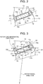
- FIG. 2 is a sectional view taken along line II-II in FIG. 1 in a part in the circumferential direction of the rotor of the rotating electric machine 10.
- the rotor of the rotating electric machine 10 might also be referred to as a rotor 10.
- the rotor 10 is used for forming the rotating electric machine 100.
- the rotating electric machine 100 will be described with reference to FIG. 1 .
- the rotating electric machine 100 is a permanent magnet type synchronous motor that drives with three-phase AC current.
- the rotating electric machine 100 is used as a motor driving a hybrid vehicle or as an electric power generator, or as a motor generator having both the functions.
- the rotating electric machine 100 includes a stator 110, the rotor 10 disposed radially inward of the stator 110, and a rotary shaft 115.
- the stator 110 is configured to include a generally cylindrical stator core 111, a stator coil 114 wound around multiple teeth 112 projecting from the inner circumferential surface of the stator core 111.
- the stator 110 is fixed to the inner side of a case (not illustrated).
- the rotor 10 is a cylindrical member configured such that the rotary shaft 115 is inserted in the rotor 10 in use.
- the rotor 10 is disposed inside the case in use. Inside the case, the rotor 10 is disposed radially inward of the stator 110 so as to face the stator 110. In this state, both ends of the rotary shaft 115 are rotatably supported by bearings (not-illustrated) relative to the case.
- a clearance in the radial direction is formed between an outer circumferential surface of the rotor 10 and an inner circumferential surface of the stator 110.
- Magnets 16 are disposed at multiple positions in the circumferential direction of the rotor 10, as described later. In this manner, the rotating electric machine 100 is formed.
- a “rotor radial direction” denotes a direction of radiation from rotor 10, that is, a radial direction of the rotor 10, and a “rotor circumferential direction” denotes a direction along in a circular shape around the central axis of the rotor 10.
- a “rotor axial direction” denotes a direction along the central axis of the rotor 10.
- the rotor 10 includes a rotor core 12, and the magnets 16 that are permanent magnets embedded in the rotor core 12 at multiple positions in the circumferential direction of the rotor core 12.
- the rotor core 12 is formed by stacking, in the axial direction, multiple disk-shaped steel plates 13 made of a magnetic material.
- a shaft hole 12a is formed in the center part of the rotor core 12, and multiple magnet holes 14 are formed around the shaft hole 12a.
- the rotary shaft 115 is fixed into the shaft hole 12a.
- the multiple magnet holes 14 are so formed as to extend in the rotor axial direction at the multiple positions in the circumferential direction of the rotor core 12.
- the magnets 16 are inserted into the magnet holes 14, and are fixed thereto by resin portions 20 described later.
- Each of the multiple magnets 16 is formed in a rectangular parallelopiped shape as a whole, and long in the rotor axial direction.
- Each magnet 16 includes two first surfaces 17a, 17b that are parallel to the rotor axial direction and face the rotor radial direction, and two second surfaces 18a, 18b that are parallel to the rotor axial direction and face the rotor circumferential direction.
- the two first surfaces 17a, 17b respectively face the outward and inward generally in the rotor radial direction.
- the two second surfaces 18a, 18b respectively face one side and the other side generally in the rotor circumferential direction.
- the multiple magnet holes 14 are arranged in such a manner that two magnet holes are defined as one set, and multiple sets of magnet holes 14 are disposed at multiple positions in the circumferential direction of the rotor core 12.
- the two magnet holes 14 in each set are arranged in a V-shape opening outward in the rotor radial direction (upward direction in FIG. 2).
- FIG. 2 shows a single magnet hole 14 of each set of the magnet holes 14.
- the magnet hole 14 includes two flat surface portions 14a, 14b, at an intermediate part of the rotor circumferential direction, that are inclined relative to the rotor circumferential direction and parallel to each other.
- a space defined between the two flat surface portions 14a, 14b is a magnet-insertion portion in a rectangular parallelepiped shape long in the rotor axial direction.
- the multiple magnets 16 are inserted into the respective magnet insertion portions of the multiple magnet holes 14 one by one. At this time, gaps are formed at both ends in the rotor circumferential direction of each magnet hole 14. Resin as a magnet fixing material in a molten state is poured into these gaps, and is hardened therein, to thereby form resin portions 20 basically extending in the axial direction. These resin portions 20 fix the magnets 16 relative to the rotor core 12. In FIG. 2 , the resin portions 20 are indicated by half-tone dot meshing. The resin portions 20 are formed by pouring the molten resin from one end of each magnet hole 14 with the magnets 16 inserted in the respective magnet holes 14, hardening the resin by heat, and cooling the resin to a normal temperature.
- FIG. 3 is a view corresponding to FIG. 2 for explaining the definitions of the first surfaces 17a, 17b and the second surfaces 18a, 18b of each magnet 16.
- the two first surfaces 17a, 17b are surfaces facing the flat surface portions 14a, 14b of each magnet hole 14, and these surfaces have angles ⁇ 1, ⁇ 2 of less than 45°, which are respectively defined by a plane D1 and a plane D2 orthogonal to the rotor radial direction.
- the first surface 17a that is one first surface of the two first surfaces 17a, 17b is a surface facing radially outward generally in the rotor radial direction
- the other first surface 17b of the first surfaces 17a, 17b is a surface facing radially inward generally in the rotor radial direction
- the two second surfaces 18a, 18b are surfaces facing the resin portions 20 located at both sides in the rotor circumferential direction.
- the two second surfaces 18a, 18b are surfaces having angles ⁇ 1, ⁇ 2 of more than 45°, which are respectively defined by the plane D1 and the plane D2 orthogonal to the rotor radial direction.
- the second surface 18a that is one second surface of the two second surfaces 18a, 18b is a surface facing one side generally in the rotor circumferential direction
- the other second surface 18b of the second surfaces 18a, 18b is a surface facing the other side generally in the rotor circumferential direction.
- the "rotor circumferential direction” indicates a direction of a tangential line of a circle that coincides with the rotor circumferential direction.
- the plane D1 and the plane D2 are parallel to this tangential line.
- each magnet 16 is a direction orthogonal to the respective first surfaces 17a, 17b.
- the magnet 16 is magnetized such that the first surface 17a located outward in the rotor radial direction of the magnet 16 becomes an N-pole, and the first surface 17b located inward in the rotor radial direction of the magnet 16 becomes an S-pole.
- the multiple magnets 16 are configured such that every two adjacent magnets 16 that form a V-shape are defined to be a single set, and each set of the magnets 16 forms a single magnetic pole.
- both ends in the rotor axial direction of each of the two first surfaces 17a, 17b are covered with electric insulating films 19.
- the electric insulating films 19 are formed by an electric insulating material such as resin, and are provided to film-forming-target portions of each magnet 16 in a film forming step.
- a lateral surface region between both ends of the first surface that are covered with the electric insulating films 19 is not covered with the electric insulating film.
- the two second surfaces 18a, 18b ( FIG. 2, FIG. 3 ) are not covered with the electric insulating films.
- each magnet 16 In a state in which each magnet 16 is inserted in each magnet hole 14, the respective both ends in the rotor axial direction of the first surfaces 17a, 17b of the magnet 16 are in contact with the respective flat surface portions 14a, 14b of the magnet hole 14 via the electric insulating films 19.
- the lateral surface regions between the respective both ends of the first surfaces 17a, 17b of the magnet 16 are out of contact with the respective flat surface portions 14a, 14b of the magnet hole 14.
- the manufacturing method of the rotor 10 includes a jig fixing step and a resin pouring step.
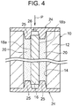
- FIG. 4 is a view showing the resin pouring step of pouring the resin into each magnet hole 14 in the manufacturing method of the rotor 10, and is a sectional view corresponding to a part in the circumferential direction of the rotor 10.
- the "jig fixing step" in a state in which each magnet 16 is disposed in each magnet hole 14, positioning jigs 24 are respectively fixed to both ends in the rotor axial direction of the rotor core 12 so as to cover openings at both ends of each magnet hole 14.
- Each positioning jig 24 is a die in a disk shape, having a lateral surface on the rotor core 12 side from which two pin projections 25 project, and the pin projections 25 are inserted in the magnet holes 14 such that two pin projections 25 project from each position of multiple positions facing the multiple magnet holes 14.
- Each pin projection 25 is formed in a truncated cone shape having a diameter gradually smaller toward its front end. The outer circumferential surfaces of the two pin projections 25 are pushed against each end in the rotor axial direction of the magnet 16, from each side in the rotor circumferential direction of the magnet 16. With this configuration, a compressing force is applied to the magnet 16 from each side by the two pin projections 25 in a direction orthogonal to the two second surfaces 18a, 18b (direction indicated by an arrow ⁇ in FIG. 2 ).
- the resin pouring step in a state in which each end of each magnet 16 is held by the two pin projections 25 of each positioning jig 24 so as to prevent movement of the magnet 16 in the direction orthogonal to the second surfaces 18a, 18b of the magnet 16, the resin is poured and hardened into the each magnet hole 14. At this time, the molten resin is poured through a resin pouring hole 26 formed in one (the upper one in FIG. 4 ) of the two positioning jigs 24 in the direction indicated by an arrow P in FIG. 4 so as to be hardened between the magnet hole 14 and the magnet 16.
- the resin pouring hole 26 is formed at a position facing the end surface in the rotor axial direction of the magnet 16.
- circular-shaped recesses 21 FIG. 2
- insertion marks of the pin projections 25 of each positioning jig 24 are formed in each end in the rotor circumferential direction of the magnet hole 14.
- the resin pouring hole may be formed in each of the two positioning jigs 24.
- the molten resin is poured into each magnet hole 14 through the resin pouring holes from both ends in the rotor axial direction of the magnet hole 14.
- the length in the rotor axial direction of the magnet 16 is shorter than the length in the rotor axial direction of the magnet hole 14, and respective spaces formed between both opening ends of each magnet hole 14 and both end surfaces in the rotor axial direction of each magnet hole 14 are also charged with the resin.
- FIG. 1 illustrates that gaps are formed between the respective lateral surface regions between the respective both ends of the first surfaces 17a, 17b of each magnet 16 that are covered with the electric insulating films 19, and the magnet hole 14, but parts corresponding to these gaps are actually charged with the resin as well.
- the multiple magnets 16 are fixed to the rotor core 12 in the above manner, to thereby form the rotor 10.
- the respective both ends in the rotor axial direction of the two first surfaces 17a, 17b parallel to the rotor axial direction are covered with the electric insulating films.
- each magnet 16 although the respective both ends in the rotor axial direction of the two first surfaces 17a, 17b are covered with the electric insulating films 19, in each of the first surfaces 17a, 17b, the lateral surface region between both ends covered with the electric insulating film 19 is not covered with the electric insulating film, either.
- the entire surfaces of the two second surfaces 18a, 18b are not covered with the electric insulating films. Accordingly, the surfaces where the electric insulating films are formed in each magnet 16 are reduced, to thereby reduce the cost for the rotor 10.
- each magnet 16 the respective both ends in the rotor axial direction of the two first surfaces 17a, 17b are covered with the electric insulating films 19. Accordingly, unlike the configuration in which the entire surfaces of each magnet 16 are not covered with electric insulating films, the two first surfaces 17a, 17b of each magnet 16 can be in contact with the inner surface of each magnet hole 14 via the electric insulating films 19, and thus it is possible to stably restrict the position in the direction orthogonal to the first surfaces of the magnet 16, inside the magnet hole 14.
- the resin is poured into each magnet hole 14 in the state in which the movement of the magnet 16 in the direction orthogonal to the second surfaces 18a, 18b of the magnet 16 is prevented by the pin projections 25 of the positioning jigs 24 ( FIG. 4 ). Accordingly, it is possible to prevent each magnet 16 from being fixed to the rotor core 12 when the second surfaces 18a, 18b of the magnet 16 comes in direct contact with the rotor core 12, thus suppressing loss worsening due to the eddy current loss.
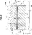
- FIG. 5 is a half sectional view of a rotating electric machine 100a including a rotor 10a of another example of the embodiment.
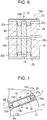
- FIG. 6 is a sectional view taken along line VI-VI of FIG. 5 in a part in the circumferential direction of the rotor 10a.
- FIG. 7 is a sectional view taken along line VII-VII of FIG. 5 in the part in the circumferential direction of the rotor 10a.
- the rotor 10a includes end plates 22 disposed on both ends in the rotor axial direction of the rotor 10a.
- Each end plate 22 is formed by a non-magnetic material in a disk shape in such a manner that the rotary shaft 115 is inserted and fixed into a center hole 22a formed in the center of the end plate 22.
- the end plate 22 is formed by aluminum, an aluminum alloy, or a non-magnetic metal such as non-magnetic stainless steel.
- the rotor core 12 is held by the two end plates 22 from both sides in the rotor axial direction of the rotor core 12.
- Each end plate 22 corresponds to a positioning member to prevent movement of the magnet 16 in the predetermined direction, as described later.
- each end plate 22 having a lateral surface on the rotor core 12 side from which two pin projections 22c project, and the pin projections 22c are inserted in the magnet holes 14 arranged such that two pin projections 22c project from each position of multiple positions facing the multiple magnet holes 14.
- Each pin projection 22c is formed in a truncated cone shape having a diameter gradually smaller toward its front end. The outer circumferential surfaces of the two pin projections 22c are pushed against each end in the rotor axial direction of the magnet 16, from each side in the rotor circumferential direction of the magnet 16.
- each end plate 22 prevents movement of each magnet 16 in the direction orthogonal to the second surfaces 18a, 18b that is a predetermined direction of the magnet 16.
- the pin projections 22c can prevent the second surfaces 18a, 18b of each magnet 16 that are formed with no electric insulating films from coming in direct contact with the rotor core 12, to thus suppress loss worsening due to the eddy current loss.
- the other configurations and operation are the same as the configurations in FIG. 1 to FIG. 4 .
- Both of the two end plates 22 may be formed with holes for the resin pouring.
- FIG. 8 is a view corresponding to FIG. 2 , and showing a rotor 10b of another example of the embodiment.
- both ends in the rotor axial direction of only the one first surface 17a (upper one in FIG. 8 ) of the first surfaces 17a, 17b are covered with the electric insulating films 19.
- the other first surface 17b (lower one in FIG. 8 ) of the two first surfaces 17a, 17b, including both ends in the rotor axial direction of the first surface 17b is entirely covered with no electric insulating films, so that the other first surface 17b is out of direct contact with the rotor core 12. Gaps between the other first surface 17b and a flat surface portion 14b of each magnet hole 14 are charged with the resin.
- each magnet hole 14 Before the resin is poured into each magnet hole 14, as with the configuration of FIG. 4 , in a state in which the positioning jigs 24 (see FIG. 4 ) are disposed at both sides in the rotor axial direction of the rotor core 12, the one first surface 17a of each magnet 16 is brought to come in contact with the flat surface portion 14a of the magnet hole 14 via the electric insulating film 19. In this state, the molten resin is poured into the magnet hole 14, and thereafter is hardened to be formed into the resin portion 20.
- the surfaces where the electric insulating films 19 are formed in each magnet 16 are further reduced, to thus further reduce the cost of the rotor 10b.
- the one first surface 17a of each magnet 16 is brought to come in contact with the inner surface of the magnet hole 14 via the electric insulating film 19 so as to stably restrict the position of the magnet 16 in the direction orthogonal to the first surface 17a of the magnet 16 in the magnet hole 14.
- the other configurations and operation are the same as those of FIG. 1 to FIG. 4 .
- the one first surface of the two first surfaces 17a, 17b of each magnet 16 is defined to be the first surface 17b that faces inward of the rotor radial direction, and the other first surface may be defined to be the first surface 17a that faces outward of the rotor radial direction.
- both ends in the rotor axial direction are covered with the electric insulating films, so that the one first surface 17b is brought to come in contact with the flat surface portion 14b of the magnet hole 14 via the electric insulating films.
- the gap between the other first surface 17a and the flat surface portion 14a of each magnet hole 14 is charged with the resin.
- the two first surfaces 17a, 17b are both formed with the electric insulating films 19, like the present example, it may be configured to bring only the one first surface of the two first surfaces 17a, 17b to come in contact with the inner surface of each magnet hole 14 via the electric insulating films 19.
- FIG. 9 is a view corresponding to FIG. 7 , and showing a rotor 10b of another example of the embodiment.
- no resin pouring holes are formed in both the two end plates 22.
- Each magnet 16 disposed in each magnet hole 14 is held by the end plates 22 that are the positioning members disposed on both ends in the rotor axial direction of the rotor 10b.
- both ends in the rotor axial direction are covered with the electric insulating films 19.
- the one first surface 17a is brought to come in contact with the inner surface of each magnet hole 14 via the electric insulating films 19.
- the other configurations and operation are the same as the configurations of FIG. 1 to FIG. 4 , the configurations of FIG. 5 to FIG. 7 , and the configurations of FIG. 8 .
- the one first surface of the two first surfaces 17a, 17b of each magnet 16 may be defined to be the first surface 17b facing inward of the rotor radial direction, and the other first surface thereof may be defined to be the first surface 17a facing outward of the rotor radial direction.
- both ends in the rotor axial direction are covered with the electric insulating films, and the one first surface 17b is brought to come in contact with the inner surface of the magnet hole 14 via the electric insulating films 19.
- the pin projections of the end plates 22 are brought to contact with each magnet 16 so as to form the gap between the other first surface 17a and the rotor core 12.
- each positioning jig 24 ( FIG. 4 ) or each end plate 22 ( FIG. 5 , FIG. 6 ) is provided with the pin projections to prevent the movement of the magnet 16; however, the shape of each projection is not limited to a pin-like shape, and various shapes, such as a block shape, may be employed. In the configurations of FIG. 1 to FIG. 4 , or in the configuration of FIG. 8 , the end plates may be disposed on both ends in the axial direction of the rotor.
- the magnets 16 are arranged at multiple positions in the circumferential direction of the rotor in such a manner that two magnets 16 in each set are disposed in a V-shape; however, the magnets may be arranged in a linear direction along the circumferential direction of each magnet in the rotor.
- two surfaces facing both sides in the rotor radial direction are the first surfaces
- two surfaces facing both sides in the rotor circumferential direction are the second surfaces.
Landscapes
- Engineering & Computer Science (AREA)
- Power Engineering (AREA)
- Manufacturing & Machinery (AREA)
- Physics & Mathematics (AREA)
- Electromagnetism (AREA)
- Permanent Field Magnets Of Synchronous Machinery (AREA)
- Iron Core Of Rotating Electric Machines (AREA)
- Permanent Magnet Type Synchronous Machine (AREA)
Applications Claiming Priority (1)
| Application Number | Priority Date | Filing Date | Title |
|---|---|---|---|
| JP2017195270A JP6874630B2 (ja) | 2017-10-05 | 2017-10-05 | 回転電機ロータ及びその製造方法 |
Publications (2)
| Publication Number | Publication Date |
|---|---|
| EP3468005A1 EP3468005A1 (en) | 2019-04-10 |
| EP3468005B1 true EP3468005B1 (en) | 2020-06-10 |
Family
ID=63294064
Family Applications (1)
| Application Number | Title | Priority Date | Filing Date |
|---|---|---|---|
| EP18189283.7A Active EP3468005B1 (en) | 2017-10-05 | 2018-08-16 | Rotor of rotating electric machine and manufacturing method of the same |
Country Status (7)
| Country | Link |
|---|---|
| US (1) | US10879778B2 (ru) |
| EP (1) | EP3468005B1 (ru) |
| JP (1) | JP6874630B2 (ru) |
| KR (1) | KR102075338B1 (ru) |
| CN (1) | CN109638995B (ru) |
| BR (1) | BR102018069040A2 (ru) |
| RU (1) | RU2700171C1 (ru) |
Families Citing this family (12)
| Publication number | Priority date | Publication date | Assignee | Title |
|---|---|---|---|---|
| JP6597594B2 (ja) * | 2016-12-27 | 2019-10-30 | トヨタ自動車株式会社 | 回転子製造装置 |
| JP6548276B2 (ja) * | 2017-10-04 | 2019-07-24 | 本田技研工業株式会社 | 回転電機のロータ |
| JP7395869B2 (ja) | 2019-08-08 | 2023-12-12 | トヨタ自動車株式会社 | 埋込磁石型のロータの製造方法 |
| DE102019126763A1 (de) * | 2019-10-04 | 2021-04-08 | Schlaeger Kunststofftechnik Gmbh | Verfahren zur Herstellung eines mit wenigstens einem Bauelement, insbesondere mit einem Funktionselement, versehenen Bauteils |
| RU2728276C1 (ru) * | 2020-01-27 | 2020-07-29 | федеральное государственное бюджетное образовательное учреждение высшего образования "Уфимский государственный авиационный технический университет" | Ротор магнитоэлектрической машины с низким уровнем нагрева постоянных магнитов (варианты) |
| JP7338570B2 (ja) * | 2020-07-01 | 2023-09-05 | トヨタ自動車株式会社 | 回転機のロータおよびその製造方法 |
| TR202012067A2 (tr) * | 2020-07-29 | 2022-02-21 | Arçeli̇k Anoni̇m Şi̇rketi̇ | Kaplamali yüzeye sahi̇p olan bi̇r miknatis i̇çeren hermeti̇k kompresör |
| CN114257052B (zh) * | 2020-09-23 | 2023-09-15 | 丰田自动车株式会社 | 旋转电机用转子的制造方法以及制造装置 |
| US11735965B2 (en) | 2021-03-22 | 2023-08-22 | Rolls-Royce Plc | Rotor assembly |
| US11870305B2 (en) | 2021-03-22 | 2024-01-09 | Rolls-Royce Singapore Pte. Ltd. | System and method for reduced rotor losses |
| FR3126077B1 (fr) * | 2021-08-04 | 2024-01-05 | Renault Sas | Procédé et outil d’assemblage d’un rotor de machine électrique |
| WO2023127756A1 (ja) * | 2021-12-28 | 2023-07-06 | ニデック株式会社 | ロータ、回転電機、およびロータの製造方法 |
Family Cites Families (22)
| Publication number | Priority date | Publication date | Assignee | Title |
|---|---|---|---|---|
| JPH08322173A (ja) | 1995-05-25 | 1996-12-03 | Mitsubishi Electric Corp | モータの回転子 |
| JP2007049805A (ja) * | 2005-08-09 | 2007-02-22 | Honda Motor Co Ltd | 永久磁石式回転子 |
| JP4893435B2 (ja) * | 2007-04-12 | 2012-03-07 | トヨタ自動車株式会社 | ロータおよびその製造方法ならびに電動車両 |
| EA201000637A1 (ru) * | 2010-03-25 | 2011-02-28 | Открытое Акционерное Общество "Нпо "Русский Электропривод"" | Электрическая машина с постоянными магнитами |
| KR101220381B1 (ko) * | 2010-12-01 | 2013-01-09 | 현대자동차주식회사 | 매입형 영구자석모터 및 이를 제작하는 방법 |
| JP5716377B2 (ja) * | 2010-12-17 | 2015-05-13 | アイシン精機株式会社 | 回転電機 |
| US20140054985A1 (en) * | 2011-02-24 | 2014-02-27 | Andritz Ritz Gmbh | Internally exicted synchronous motor comprising a permanent magnet rotor with multiple corrosion protection |
| WO2012124072A1 (ja) * | 2011-03-16 | 2012-09-20 | トヨタ自動車株式会社 | ロータおよび回転電機 |
| JP2012244838A (ja) * | 2011-05-23 | 2012-12-10 | Toyota Motor Corp | 回転電機用ロータ、回転電機、および、回転電機用ロータの製造方法 |
| WO2012169043A1 (ja) * | 2011-06-09 | 2012-12-13 | トヨタ自動車株式会社 | 回転電機用ロータ、回転電機、および、回転電機用ロータの製造方法 |
| DE102012202529A1 (de) | 2012-02-20 | 2013-08-22 | Robert Bosch Gmbh | Dauermagnetfixierung mittels einer Einfassung |
| DE102012205361A1 (de) * | 2012-04-02 | 2013-10-02 | Robert Bosch Gmbh | Bürstenlose elektrische Maschine mit vergrabenen Dauermagneten |
| WO2014054150A1 (ja) * | 2012-10-04 | 2014-04-10 | 三菱電機株式会社 | 永久磁石埋込型電動機 |
| JP5981295B2 (ja) * | 2012-10-12 | 2016-08-31 | 株式会社三井ハイテック | 積層鉄心の樹脂封止方法 |
| JP2015023620A (ja) * | 2013-07-17 | 2015-02-02 | トヨタ自動車株式会社 | モータ |
| JP2015061487A (ja) * | 2013-09-20 | 2015-03-30 | 本田技研工業株式会社 | 回転子の製造方法 |
| JP2015100157A (ja) * | 2013-11-18 | 2015-05-28 | トヨタ自動車株式会社 | ロータの製造方法 |
| JP5972249B2 (ja) * | 2013-11-27 | 2016-08-17 | 三菱電機株式会社 | 磁石埋込型回転子 |
| JP2016005419A (ja) * | 2014-06-19 | 2016-01-12 | 日立アプライアンス株式会社 | 永久磁石電動機 |
| JP6464822B2 (ja) | 2015-02-27 | 2019-02-06 | 日本電産株式会社 | モータ |
| JP2017093038A (ja) * | 2015-11-04 | 2017-05-25 | トヨタ自動車株式会社 | 回転電機のロータ |
| DE102015225523A1 (de) * | 2015-12-17 | 2017-06-22 | Em-Motive Gmbh | Rotor einer elektrischen Maschine |
-
2017
- 2017-10-05 JP JP2017195270A patent/JP6874630B2/ja active Active
-
2018
- 2018-08-09 US US16/059,820 patent/US10879778B2/en active Active
- 2018-08-10 KR KR1020180093694A patent/KR102075338B1/ko active IP Right Grant
- 2018-08-16 EP EP18189283.7A patent/EP3468005B1/en active Active
- 2018-08-16 CN CN201810934160.1A patent/CN109638995B/zh active Active
- 2018-09-19 BR BR102018069040-0A patent/BR102018069040A2/pt not_active Application Discontinuation
- 2018-09-20 RU RU2018133287A patent/RU2700171C1/ru active
Non-Patent Citations (1)
| Title |
|---|
| None * |
Also Published As
| Publication number | Publication date |
|---|---|
| RU2700171C1 (ru) | 2019-09-13 |
| JP2019068701A (ja) | 2019-04-25 |
| BR102018069040A2 (pt) | 2019-04-24 |
| US10879778B2 (en) | 2020-12-29 |
| KR102075338B1 (ko) | 2020-02-10 |
| KR20190039636A (ko) | 2019-04-15 |
| JP6874630B2 (ja) | 2021-05-19 |
| US20190109525A1 (en) | 2019-04-11 |
| CN109638995A (zh) | 2019-04-16 |
| CN109638995B (zh) | 2021-02-19 |
| EP3468005A1 (en) | 2019-04-10 |
Similar Documents
| Publication | Publication Date | Title |
|---|---|---|
| EP3468005B1 (en) | Rotor of rotating electric machine and manufacturing method of the same | |
| WO2014034344A1 (ja) | 回転電機 | |
| JP4457785B2 (ja) | ディスク型回転電機のステータ構造 | |
| EP3018802B1 (en) | Method for producing a rotor | |
| EP3145056B1 (en) | Rotary electric machine and stator of rotary electric machine | |
| JP5274091B2 (ja) | 回転電機の固定子製造方法 | |
| JP2014121202A (ja) | 埋込磁石型同期電動機の回転子および埋込磁石型同期電動機 | |
| WO2018074561A1 (ja) | 同期リラクタンス型回転電機 | |
| US10658893B2 (en) | Rotary electric-machine rotor | |
| JP2014003795A (ja) | 回転子およびその製造方法ならびに永久磁石モータ | |
| US20160226355A1 (en) | Magnetic inductor electric motor | |
| JP7424842B2 (ja) | 回転電機 | |
| JP6357859B2 (ja) | 永久磁石埋め込み式回転電機 | |
| JP2011125163A (ja) | 電動機ロータ | |
| JP7363295B2 (ja) | ホルダ、ロータ、モータ、およびロータの製造方法 | |
| JP2007074844A (ja) | ステータコア、モータ | |
| JP7149497B2 (ja) | ブラシレスモータ及びブラシレスモータの製造方法 | |
| JP7363296B2 (ja) | ホルダ、ロータ、モータ、およびロータの製造方法 | |
| US11901771B2 (en) | Rotating electric machine | |
| JP5359526B2 (ja) | 永久磁石同期電動機の回転子 | |
| JP2001037116A (ja) | 回転機のステータコア | |
| JP2006020425A (ja) | モータのロータ | |
| JP2006166571A (ja) | 回転電機の回転子構造 |
Legal Events
| Date | Code | Title | Description |
|---|---|---|---|
| PUAI | Public reference made under article 153(3) epc to a published international application that has entered the european phase |
Free format text: ORIGINAL CODE: 0009012 |
|
| STAA | Information on the status of an ep patent application or granted ep patent |
Free format text: STATUS: REQUEST FOR EXAMINATION WAS MADE |
|
| 17P | Request for examination filed |
Effective date: 20180917 |
|
| AK | Designated contracting states |
Kind code of ref document: A1 Designated state(s): AL AT BE BG CH CY CZ DE DK EE ES FI FR GB GR HR HU IE IS IT LI LT LU LV MC MK MT NL NO PL PT RO RS SE SI SK SM TR |
|
| AX | Request for extension of the european patent |
Extension state: BA ME |
|
| RIC1 | Information provided on ipc code assigned before grant |
Ipc: H02K 15/03 20060101ALI20191121BHEP Ipc: H02K 1/27 20060101AFI20191121BHEP Ipc: H02K 11/01 20160101ALI20191121BHEP |
|
| GRAP | Despatch of communication of intention to grant a patent |
Free format text: ORIGINAL CODE: EPIDOSNIGR1 |
|
| STAA | Information on the status of an ep patent application or granted ep patent |
Free format text: STATUS: GRANT OF PATENT IS INTENDED |
|
| INTG | Intention to grant announced |
Effective date: 20200107 |
|
| GRAS | Grant fee paid |
Free format text: ORIGINAL CODE: EPIDOSNIGR3 |
|
| GRAA | (expected) grant |
Free format text: ORIGINAL CODE: 0009210 |
|
| STAA | Information on the status of an ep patent application or granted ep patent |
Free format text: STATUS: THE PATENT HAS BEEN GRANTED |
|
| AK | Designated contracting states |
Kind code of ref document: B1 Designated state(s): AL AT BE BG CH CY CZ DE DK EE ES FI FR GB GR HR HU IE IS IT LI LT LU LV MC MK MT NL NO PL PT RO RS SE SI SK SM TR |
|
| REG | Reference to a national code |
Ref country code: GB Ref legal event code: FG4D |
|
| REG | Reference to a national code |
Ref country code: CH Ref legal event code: EP Ref country code: AT Ref legal event code: REF Ref document number: 1279958 Country of ref document: AT Kind code of ref document: T Effective date: 20200615 |
|
| REG | Reference to a national code |
Ref country code: DE Ref legal event code: R096 Ref document number: 602018005171 Country of ref document: DE |
|
| REG | Reference to a national code |
Ref country code: IE Ref legal event code: FG4D |
|
| REG | Reference to a national code |
Ref country code: LT Ref legal event code: MG4D |
|
| PG25 | Lapsed in a contracting state [announced via postgrant information from national office to epo] |
Ref country code: LT Free format text: LAPSE BECAUSE OF FAILURE TO SUBMIT A TRANSLATION OF THE DESCRIPTION OR TO PAY THE FEE WITHIN THE PRESCRIBED TIME-LIMIT Effective date: 20200610 Ref country code: SE Free format text: LAPSE BECAUSE OF FAILURE TO SUBMIT A TRANSLATION OF THE DESCRIPTION OR TO PAY THE FEE WITHIN THE PRESCRIBED TIME-LIMIT Effective date: 20200610 Ref country code: GR Free format text: LAPSE BECAUSE OF FAILURE TO SUBMIT A TRANSLATION OF THE DESCRIPTION OR TO PAY THE FEE WITHIN THE PRESCRIBED TIME-LIMIT Effective date: 20200911 Ref country code: NO Free format text: LAPSE BECAUSE OF FAILURE TO SUBMIT A TRANSLATION OF THE DESCRIPTION OR TO PAY THE FEE WITHIN THE PRESCRIBED TIME-LIMIT Effective date: 20200910 Ref country code: FI Free format text: LAPSE BECAUSE OF FAILURE TO SUBMIT A TRANSLATION OF THE DESCRIPTION OR TO PAY THE FEE WITHIN THE PRESCRIBED TIME-LIMIT Effective date: 20200610 |
|
| REG | Reference to a national code |
Ref country code: NL Ref legal event code: MP Effective date: 20200610 |
|
| PG25 | Lapsed in a contracting state [announced via postgrant information from national office to epo] |
Ref country code: BG Free format text: LAPSE BECAUSE OF FAILURE TO SUBMIT A TRANSLATION OF THE DESCRIPTION OR TO PAY THE FEE WITHIN THE PRESCRIBED TIME-LIMIT Effective date: 20200910 Ref country code: LV Free format text: LAPSE BECAUSE OF FAILURE TO SUBMIT A TRANSLATION OF THE DESCRIPTION OR TO PAY THE FEE WITHIN THE PRESCRIBED TIME-LIMIT Effective date: 20200610 Ref country code: HR Free format text: LAPSE BECAUSE OF FAILURE TO SUBMIT A TRANSLATION OF THE DESCRIPTION OR TO PAY THE FEE WITHIN THE PRESCRIBED TIME-LIMIT Effective date: 20200610 Ref country code: RS Free format text: LAPSE BECAUSE OF FAILURE TO SUBMIT A TRANSLATION OF THE DESCRIPTION OR TO PAY THE FEE WITHIN THE PRESCRIBED TIME-LIMIT Effective date: 20200610 |
|
| REG | Reference to a national code |
Ref country code: AT Ref legal event code: MK05 Ref document number: 1279958 Country of ref document: AT Kind code of ref document: T Effective date: 20200610 |
|
| PG25 | Lapsed in a contracting state [announced via postgrant information from national office to epo] |
Ref country code: AL Free format text: LAPSE BECAUSE OF FAILURE TO SUBMIT A TRANSLATION OF THE DESCRIPTION OR TO PAY THE FEE WITHIN THE PRESCRIBED TIME-LIMIT Effective date: 20200610 Ref country code: NL Free format text: LAPSE BECAUSE OF FAILURE TO SUBMIT A TRANSLATION OF THE DESCRIPTION OR TO PAY THE FEE WITHIN THE PRESCRIBED TIME-LIMIT Effective date: 20200610 |
|
| PG25 | Lapsed in a contracting state [announced via postgrant information from national office to epo] |
Ref country code: AT Free format text: LAPSE BECAUSE OF FAILURE TO SUBMIT A TRANSLATION OF THE DESCRIPTION OR TO PAY THE FEE WITHIN THE PRESCRIBED TIME-LIMIT Effective date: 20200610 Ref country code: EE Free format text: LAPSE BECAUSE OF FAILURE TO SUBMIT A TRANSLATION OF THE DESCRIPTION OR TO PAY THE FEE WITHIN THE PRESCRIBED TIME-LIMIT Effective date: 20200610 Ref country code: PT Free format text: LAPSE BECAUSE OF FAILURE TO SUBMIT A TRANSLATION OF THE DESCRIPTION OR TO PAY THE FEE WITHIN THE PRESCRIBED TIME-LIMIT Effective date: 20201012 Ref country code: ES Free format text: LAPSE BECAUSE OF FAILURE TO SUBMIT A TRANSLATION OF THE DESCRIPTION OR TO PAY THE FEE WITHIN THE PRESCRIBED TIME-LIMIT Effective date: 20200610 Ref country code: CZ Free format text: LAPSE BECAUSE OF FAILURE TO SUBMIT A TRANSLATION OF THE DESCRIPTION OR TO PAY THE FEE WITHIN THE PRESCRIBED TIME-LIMIT Effective date: 20200610 Ref country code: RO Free format text: LAPSE BECAUSE OF FAILURE TO SUBMIT A TRANSLATION OF THE DESCRIPTION OR TO PAY THE FEE WITHIN THE PRESCRIBED TIME-LIMIT Effective date: 20200610 Ref country code: IT Free format text: LAPSE BECAUSE OF FAILURE TO SUBMIT A TRANSLATION OF THE DESCRIPTION OR TO PAY THE FEE WITHIN THE PRESCRIBED TIME-LIMIT Effective date: 20200610 Ref country code: SM Free format text: LAPSE BECAUSE OF FAILURE TO SUBMIT A TRANSLATION OF THE DESCRIPTION OR TO PAY THE FEE WITHIN THE PRESCRIBED TIME-LIMIT Effective date: 20200610 |
|
| PG25 | Lapsed in a contracting state [announced via postgrant information from national office to epo] |
Ref country code: SK Free format text: LAPSE BECAUSE OF FAILURE TO SUBMIT A TRANSLATION OF THE DESCRIPTION OR TO PAY THE FEE WITHIN THE PRESCRIBED TIME-LIMIT Effective date: 20200610 Ref country code: PL Free format text: LAPSE BECAUSE OF FAILURE TO SUBMIT A TRANSLATION OF THE DESCRIPTION OR TO PAY THE FEE WITHIN THE PRESCRIBED TIME-LIMIT Effective date: 20200610 Ref country code: IS Free format text: LAPSE BECAUSE OF FAILURE TO SUBMIT A TRANSLATION OF THE DESCRIPTION OR TO PAY THE FEE WITHIN THE PRESCRIBED TIME-LIMIT Effective date: 20201010 |
|
| REG | Reference to a national code |
Ref country code: DE Ref legal event code: R097 Ref document number: 602018005171 Country of ref document: DE |
|
| PG25 | Lapsed in a contracting state [announced via postgrant information from national office to epo] |
Ref country code: MC Free format text: LAPSE BECAUSE OF FAILURE TO SUBMIT A TRANSLATION OF THE DESCRIPTION OR TO PAY THE FEE WITHIN THE PRESCRIBED TIME-LIMIT Effective date: 20200610 |
|
| PLBE | No opposition filed within time limit |
Free format text: ORIGINAL CODE: 0009261 |
|
| STAA | Information on the status of an ep patent application or granted ep patent |
Free format text: STATUS: NO OPPOSITION FILED WITHIN TIME LIMIT |
|
| PG25 | Lapsed in a contracting state [announced via postgrant information from national office to epo] |
Ref country code: DK Free format text: LAPSE BECAUSE OF FAILURE TO SUBMIT A TRANSLATION OF THE DESCRIPTION OR TO PAY THE FEE WITHIN THE PRESCRIBED TIME-LIMIT Effective date: 20200610 Ref country code: LU Free format text: LAPSE BECAUSE OF NON-PAYMENT OF DUE FEES Effective date: 20200816 |
|
| 26N | No opposition filed |
Effective date: 20210311 |
|
| REG | Reference to a national code |
Ref country code: BE Ref legal event code: MM Effective date: 20200831 |
|
| PG25 | Lapsed in a contracting state [announced via postgrant information from national office to epo] |
Ref country code: SI Free format text: LAPSE BECAUSE OF FAILURE TO SUBMIT A TRANSLATION OF THE DESCRIPTION OR TO PAY THE FEE WITHIN THE PRESCRIBED TIME-LIMIT Effective date: 20200610 |
|
| PG25 | Lapsed in a contracting state [announced via postgrant information from national office to epo] |
Ref country code: IE Free format text: LAPSE BECAUSE OF NON-PAYMENT OF DUE FEES Effective date: 20200816 Ref country code: BE Free format text: LAPSE BECAUSE OF NON-PAYMENT OF DUE FEES Effective date: 20200831 |
|
| REG | Reference to a national code |
Ref country code: CH Ref legal event code: PL |
|
| PG25 | Lapsed in a contracting state [announced via postgrant information from national office to epo] |
Ref country code: LI Free format text: LAPSE BECAUSE OF NON-PAYMENT OF DUE FEES Effective date: 20210831 Ref country code: CH Free format text: LAPSE BECAUSE OF NON-PAYMENT OF DUE FEES Effective date: 20210831 |
|
| PG25 | Lapsed in a contracting state [announced via postgrant information from national office to epo] |
Ref country code: TR Free format text: LAPSE BECAUSE OF FAILURE TO SUBMIT A TRANSLATION OF THE DESCRIPTION OR TO PAY THE FEE WITHIN THE PRESCRIBED TIME-LIMIT Effective date: 20200610 Ref country code: MT Free format text: LAPSE BECAUSE OF FAILURE TO SUBMIT A TRANSLATION OF THE DESCRIPTION OR TO PAY THE FEE WITHIN THE PRESCRIBED TIME-LIMIT Effective date: 20200610 Ref country code: CY Free format text: LAPSE BECAUSE OF FAILURE TO SUBMIT A TRANSLATION OF THE DESCRIPTION OR TO PAY THE FEE WITHIN THE PRESCRIBED TIME-LIMIT Effective date: 20200610 |
|
| PG25 | Lapsed in a contracting state [announced via postgrant information from national office to epo] |
Ref country code: MK Free format text: LAPSE BECAUSE OF FAILURE TO SUBMIT A TRANSLATION OF THE DESCRIPTION OR TO PAY THE FEE WITHIN THE PRESCRIBED TIME-LIMIT Effective date: 20200610 |
|
| P01 | Opt-out of the competence of the unified patent court (upc) registered |
Effective date: 20230427 |
|
| REG | Reference to a national code |
Ref country code: DE Ref legal event code: R084 Ref document number: 602018005171 Country of ref document: DE |
|
| REG | Reference to a national code |
Ref country code: GB Ref legal event code: 746 Effective date: 20230825 |
|
| PGFP | Annual fee paid to national office [announced via postgrant information from national office to epo] |
Ref country code: GB Payment date: 20230629 Year of fee payment: 6 |
|
| PGFP | Annual fee paid to national office [announced via postgrant information from national office to epo] |
Ref country code: FR Payment date: 20230703 Year of fee payment: 6 Ref country code: DE Payment date: 20230627 Year of fee payment: 6 |