EP3451439B1 - Komposit-anode struktur für lithium-luft-batterie - Google Patents
Komposit-anode struktur für lithium-luft-batterie Download PDFInfo
- Publication number
- EP3451439B1 EP3451439B1 EP17789176.9A EP17789176A EP3451439B1 EP 3451439 B1 EP3451439 B1 EP 3451439B1 EP 17789176 A EP17789176 A EP 17789176A EP 3451439 B1 EP3451439 B1 EP 3451439B1
- Authority
- EP
- European Patent Office
- Prior art keywords
- anode
- lithium
- current collector
- separator
- layer
- Prior art date
- Legal status (The legal status is an assumption and is not a legal conclusion. Google has not performed a legal analysis and makes no representation as to the accuracy of the status listed.)
- Active
Links
Images




Classifications
-
- H—ELECTRICITY
- H01—ELECTRIC ELEMENTS
- H01M—PROCESSES OR MEANS, e.g. BATTERIES, FOR THE DIRECT CONVERSION OF CHEMICAL ENERGY INTO ELECTRICAL ENERGY
- H01M12/00—Hybrid cells; Manufacture thereof
- H01M12/04—Hybrid cells; Manufacture thereof composed of a half-cell of the fuel-cell type and of a half-cell of the primary-cell type
- H01M12/06—Hybrid cells; Manufacture thereof composed of a half-cell of the fuel-cell type and of a half-cell of the primary-cell type with one metallic and one gaseous electrode
-
- H—ELECTRICITY
- H01—ELECTRIC ELEMENTS
- H01M—PROCESSES OR MEANS, e.g. BATTERIES, FOR THE DIRECT CONVERSION OF CHEMICAL ENERGY INTO ELECTRICAL ENERGY
- H01M4/00—Electrodes
- H01M4/02—Electrodes composed of, or comprising, active material
- H01M4/13—Electrodes for accumulators with non-aqueous electrolyte, e.g. for lithium-accumulators; Processes of manufacture thereof
- H01M4/134—Electrodes based on metals, Si or alloys
-
- H—ELECTRICITY
- H01—ELECTRIC ELEMENTS
- H01M—PROCESSES OR MEANS, e.g. BATTERIES, FOR THE DIRECT CONVERSION OF CHEMICAL ENERGY INTO ELECTRICAL ENERGY
- H01M4/00—Electrodes
- H01M4/02—Electrodes composed of, or comprising, active material
- H01M4/36—Selection of substances as active materials, active masses, active liquids
- H01M4/38—Selection of substances as active materials, active masses, active liquids of elements or alloys
- H01M4/381—Alkaline or alkaline earth metals elements
- H01M4/382—Lithium
-
- H—ELECTRICITY
- H01—ELECTRIC ELEMENTS
- H01M—PROCESSES OR MEANS, e.g. BATTERIES, FOR THE DIRECT CONVERSION OF CHEMICAL ENERGY INTO ELECTRICAL ENERGY
- H01M4/00—Electrodes
- H01M4/02—Electrodes composed of, or comprising, active material
- H01M4/36—Selection of substances as active materials, active masses, active liquids
- H01M4/38—Selection of substances as active materials, active masses, active liquids of elements or alloys
- H01M4/40—Alloys based on alkali metals
- H01M4/405—Alloys based on lithium
-
- H—ELECTRICITY
- H01—ELECTRIC ELEMENTS
- H01M—PROCESSES OR MEANS, e.g. BATTERIES, FOR THE DIRECT CONVERSION OF CHEMICAL ENERGY INTO ELECTRICAL ENERGY
- H01M4/00—Electrodes
- H01M4/02—Electrodes composed of, or comprising, active material
- H01M4/64—Carriers or collectors
- H01M4/66—Selection of materials
-
- H—ELECTRICITY
- H01—ELECTRIC ELEMENTS
- H01M—PROCESSES OR MEANS, e.g. BATTERIES, FOR THE DIRECT CONVERSION OF CHEMICAL ENERGY INTO ELECTRICAL ENERGY
- H01M4/00—Electrodes
- H01M4/02—Electrodes composed of, or comprising, active material
- H01M4/64—Carriers or collectors
- H01M4/70—Carriers or collectors characterised by shape or form
-
- H—ELECTRICITY
- H01—ELECTRIC ELEMENTS
- H01M—PROCESSES OR MEANS, e.g. BATTERIES, FOR THE DIRECT CONVERSION OF CHEMICAL ENERGY INTO ELECTRICAL ENERGY
- H01M50/00—Constructional details or processes of manufacture of the non-active parts of electrochemical cells other than fuel cells, e.g. hybrid cells
- H01M50/10—Primary casings; Jackets or wrappings
- H01M50/138—Primary casings; Jackets or wrappings adapted for specific cells, e.g. electrochemical cells operating at high temperature
- H01M50/1385—Hybrid cells
-
- H—ELECTRICITY
- H01—ELECTRIC ELEMENTS
- H01M—PROCESSES OR MEANS, e.g. BATTERIES, FOR THE DIRECT CONVERSION OF CHEMICAL ENERGY INTO ELECTRICAL ENERGY
- H01M50/00—Constructional details or processes of manufacture of the non-active parts of electrochemical cells other than fuel cells, e.g. hybrid cells
- H01M50/40—Separators; Membranes; Diaphragms; Spacing elements inside cells
- H01M50/46—Separators, membranes or diaphragms characterised by their combination with electrodes
-
- H—ELECTRICITY
- H01—ELECTRIC ELEMENTS
- H01M—PROCESSES OR MEANS, e.g. BATTERIES, FOR THE DIRECT CONVERSION OF CHEMICAL ENERGY INTO ELECTRICAL ENERGY
- H01M50/00—Constructional details or processes of manufacture of the non-active parts of electrochemical cells other than fuel cells, e.g. hybrid cells
- H01M50/40—Separators; Membranes; Diaphragms; Spacing elements inside cells
- H01M50/463—Separators, membranes or diaphragms characterised by their shape
- H01M50/466—U-shaped, bag-shaped or folded
-
- H—ELECTRICITY
- H01—ELECTRIC ELEMENTS
- H01M—PROCESSES OR MEANS, e.g. BATTERIES, FOR THE DIRECT CONVERSION OF CHEMICAL ENERGY INTO ELECTRICAL ENERGY
- H01M12/00—Hybrid cells; Manufacture thereof
- H01M12/08—Hybrid cells; Manufacture thereof composed of a half-cell of a fuel-cell type and a half-cell of the secondary-cell type
-
- H—ELECTRICITY
- H01—ELECTRIC ELEMENTS
- H01M—PROCESSES OR MEANS, e.g. BATTERIES, FOR THE DIRECT CONVERSION OF CHEMICAL ENERGY INTO ELECTRICAL ENERGY
- H01M4/00—Electrodes
- H01M4/02—Electrodes composed of, or comprising, active material
- H01M2004/026—Electrodes composed of, or comprising, active material characterised by the polarity
- H01M2004/027—Negative electrodes
-
- Y—GENERAL TAGGING OF NEW TECHNOLOGICAL DEVELOPMENTS; GENERAL TAGGING OF CROSS-SECTIONAL TECHNOLOGIES SPANNING OVER SEVERAL SECTIONS OF THE IPC; TECHNICAL SUBJECTS COVERED BY FORMER USPC CROSS-REFERENCE ART COLLECTIONS [XRACs] AND DIGESTS
- Y02—TECHNOLOGIES OR APPLICATIONS FOR MITIGATION OR ADAPTATION AGAINST CLIMATE CHANGE
- Y02E—REDUCTION OF GREENHOUSE GAS [GHG] EMISSIONS, RELATED TO ENERGY GENERATION, TRANSMISSION OR DISTRIBUTION
- Y02E60/00—Enabling technologies; Technologies with a potential or indirect contribution to GHG emissions mitigation
- Y02E60/10—Energy storage using batteries
Definitions
- the present invention relates to an anode composite structure for use in a lithium-air battery.
- metal-air batteries have been proposed as next-generation batteries that provide higher energy density than conventional lithium-ion batteries.
- a metal-air battery is a battery that uses metal as an anode active material and oxygen in the air as a cathode active material. It is said that a metal-air battery theoretically yields more energy per unit weight when metallic lithium is used as its anode active material, and such a configuration is particularly a focus of attention.
- Such an air-metal battery using metallic lithium as an anode active material is called a lithium-air battery.
- Lithium-air batteries are roughly grouped into two types: ones using an aqueous electrolyte inside and ones using a non-aqueous electrolyte inside.
- Lithium-air batteries using an aqueous electrolyte have the advantage of being less susceptible to moisture in the air than the ones using a non-aqueous electrolyte.
- metallic lithium used as an anode active material reacts chemically by coming into contact with oxygen or water and therefore needs to be isolated from the atmosphere or an aqueous solution.
- a method has been proposed to provide, for example, a solid electrolyte that conducts lithium ions as an isolation layer.
- Japanese Patent application JP 2010 192313 A discloses a lithium-air battery using an aqueous electrolyte and having an anode composite in which a polymer electrolyte buffer layer is formed on one side of a metallic lithium plate and is then covered with a glass ceramic that conducts lithium ions.
- US patent application US 2014 / 234732 A1 discloses protected lithium electrodes having a porous electrolyte interlayer and associated battery cells.
- Active metal and active metal intercalation electrode structures and battery cells have ionically conductive protective architecture including an active metal (e.g., lithium) conductive impervious layer separated from the electrode (anode) by a porous separator impregnated with a non-aqueous electrolyte (anolyte).
- This protective architecture prevents the active metal from deleterious reaction with the environment on the other (cathode) side of the impervious layer, which may include aqueous or non-aqueous liquid electrolytes (catholytes) and/or a variety of electrochemically active materials, including liquid, solid and gaseous oxidizers.
- aqueous or non-aqueous liquid electrolytes catholytes
- electrochemically active materials including liquid, solid and gaseous oxidizers.
- US patent application US 2012 / 100440 A1 describes multi-layered, chemically bonded lithium-ion and lithium/air batteries.
- multilayer, porous, thin-layered lithium-ion batteries that include an inorganic separator as a thin layer that is chemically bonded to surfaces of positive and negative electrode layers.
- the electrodes and separator are made to form non-discrete (i.e., integral) thin layers.
- methods of fabricating integrally connected, thin, multilayer lithium batteries including lithium-ion and lithium/air batteries.
- Japanese patent application JP 2016 009525 A describes a negative composite material of a lithium air battery, a lithium air battery and a lithium air battery system that can suppress extreme increase in size and implement light weight and compact size even when energy density and input/output density are increased as compared with conventional air batteries.
- a negative electrode composite material of a lithium air battery has a plate-like or linear negative electrode collector, two plate-like negative layers which contain metal lithium, lithium alloy or a lithium component and pinches a part of the negative electrode collector, and an isolation layer which is configured in a hollow box-like shape opened at one surface thereof, contains the two negative layers therein and has lithium ion conductivity.
- US patent application US 2014 / 0162108 A1 discloses a lithium battery with protected anode architectures.
- Protected anode architectures provide a hermetic enclosure for an active metal (e.g., alkali metal, such as lithium) anode inside an anode compartment.
- an active metal e.g., alkali metal, such as lithium
- the compartment is substantially impervious to ambient moisture and battery components such as catholyte (electrolyte about the cathode, and in some aspects catholyte may also comprise dissolved or suspended redox active species and redox active liquids), and prevents volatile components of the protected anode, such as anolyte (electrolyte about the anode), from escaping, while allowing for active metal ion transport between the anode and cathode into and out of the anode compartment.
- metallic lithium for use as the anode active material is placed on a metal that serves as an anode terminal (an anode current collector).
- an anode current collector an anode current collector
- dendrites of metallic lithium may be deposited onto part of the anode terminal (e.g., the back surface) during charging.
- minute lithium powder dead lithium
- the lithium powder thus dispersed drifts away from the anode terminal and floats, and therefore no longer contributes to the charge and discharge. Consequently, as the dead lithium increases, the charge-discharge performance of the lithium-air battery gradually degrades.
- the present invention has an objective to provide an anode composite structure for use in a lithium-air battery that makes the lithium-air battery less likely to degrade in charge-discharge performance.
- an anode composite structure for a lithium-air battery comprises: a solid electrolyte, above which an air electrode is placed; an anode current collector; an anode layer stacked on the anode current collector, the anode layer being metallic lithium, an alloy containing lithium as a main component, or a chemical compound containing lithium as a main component, wherein the anode layer is stacked on a surface of the anode current collector over a range smaller than an area of the anode current collector and is isolated from the solid electrolyte; and a separator stacked on the anode layer, wherein the anode layer is sealed in by the separator and the anode current collector.
- the anode composite structure comprises an electron conducting layer on an inner side of the separator.
- the present invention can provide an anode composite structure for use in a lithium-air battery which makes the lithium-air battery less likely to degrade in charge-discharge performance.
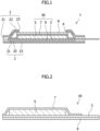
- an anode composite structure for a lithium-air battery according to a first embodiment is described using FIG. 1 .
- an anode composite 1 for a lithium-air battery according to the first embodiment has a stacking structure in which upper and lower metallic foil laminated films 2, 2 sandwich a solid electrolyte 8 and an anode 30.
- the upper metallic foil laminated film 2 in FIG. 1 is a sheet made up of three layers: a resin layer 21, a metallic foil layer 22, and a resin layer 23 stacked in the order mentioned from inside (down in FIG. 1 ) to outside (up in FIG. 1 ).
- the lower metallic foil laminated film 2 in FIG. 1 is a sheet made up of three layers: a resin layer 21, a metallic foil layer 22, and a resin layer 23 stacked in the order mentioned from inside (up in FIG. 1 ) to outside (down in FIG. 1 ).
- the upper metallic foil laminated film 2 in FIG. 1 is provided with an opening 4 at its center or almost center.
- the opening 4 is square when seen from above in FIG. 1 .
- the solid electrolyte 8 is disposed below the opening 4 of the metallic foil laminated film 2.
- the solid electrolyte 8 herein refers to a solid substance that permits ions (lithium ions) to pass therethrough when applied with voltage.
- the solid electrolyte 8 is shaped like a relatively thin plate.
- the size of the upper surface of the solid electrolyte 8 is slightly larger than the opening 4 in the metallic foil laminated film 2. Thereby, the solid electrolyte 8 plugs the opening 4.
- the anode 30 is disposed below the solid electrolyte 8 in FIG. 1 .
- the anode 30 is fixed with all its four side end portions in FIG. 1 being sandwiched by the upper and lower metallic foil laminated films 2 and welded.
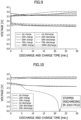
- FIG. 2 is a diagram magnifying the anode 30 in FIG. 1 .
- the anode 30 is structured as a quadruple-layer stack of, from down to up in FIG. 2 , a film 9, an anode current collector 3, an anode layer 5 (metallic lithium), and a separator 7.
- the film 9 covers the lower surface of the anode current collector 3.
- the anode layer 5 is sealed in by the anode current collector 3 and the separator 7. This structure will be further specified by descriptions given later with reference to FIG. 3 .
- the separator 7 has properties that pass an electrolyte to be described later and conduct lithium ions. Further, the separator 7 is joined at its left and right end surfaces in FIG. 2 to the anode current collector 3. The separator 7 is also joined to the anode current collector 3 at its end portion at the near side in FIG. 2 and its end portion at the far side in FIG. 2 , and by thus being joined at all the four sides, seals the anode layer 5 on the surface of the anode current collector 3. With such a configuration, the anode layer 5 is isolated from and is in no direct contact with the solid electrolyte 8.
- electrolyte such as, for example, a non-aqueous electrolytic solution, an organic electrolytic solution, or a polymer electrolyte
- electrolyte such as, for example, a non-aqueous electrolytic solution, an organic electrolytic solution, or a polymer electrolyte
- FIG. 3 is a diagram of the anode 30 seen from above in FIG. 2 .
- the anode current collector 3 has a current collecting portion 31 located on the left hand in FIG. 3 and a terminal portion 32 located on the right hand in the drawing.
- the current collecting portion 31 has the shape of a square whose area is larger than the terminal portion 32.
- the anode layer 5 and the separator 7 are stacked.
- the separator 7 is joined to the anode current collector 3 at a joint portion 73.
- the anode layer 5 is sealed in between the separator 7 and the anode current collector 3. This forms a sealing structure of the anode layer 5.
- the size of the anode layer 5 is comparable to or slightly smaller than that of the non-joint portion 75. Note that as illustrated in FIG. 1 , the non-joint portion 75 is located at a position that almost coincides with the solid electrolyte 8 provided in an upper part of FIG. 1 .
- FIG. 4 is a diagram of the anode 30 seen from below in FIG. 2 .
- the current collecting portion 31 of the anode current collector 3 is covered with the film 9 over its entire surface.
- This film 9 is made of, for example, a resinous sheet that does not transmit an electrolytic solution therethrough and does not easily deteriorate because of an electrolytic solution.
- an air electrode (not shown) is placed above the solid electrolyte 8 in FIG. 1 and used. While this lithium air battery using the anode composite 1 is discharging, the anode layer 5 (metallic lithium) used in the anode 30 produces lithium ions (Li + ) and electrons (e - ) as shown in Chemical Formula 1. Then, the lithium ions (Li + ) are dissolved in the electrolytic solution, and the electrons (e - ) are supplied to the terminal portion 32 via the current collecting portion 31 of the anode current collector 3. Thus, changing the thickness and the area of the anode layer 5 enables control of a design value for the battery capacity. [Chem. 1] Li ⁇ Li + + e -
- the separator 7 is joined to the current collecting portion 31 at the joint portion 73.
- the surface of the current collecting portion 31 is not exposed, and the metallic lithium deposition reaction does not occur.
- the metallic lithium deposition reaction occurs only at the non-joint portion 75 in FIG. 3 .
- the back surface of the current collecting portion 31, on the other hand, is covered with the film 9, as illustrated in FIG. 4 .
- the electrolytic solution does not reach the back surface of the current collecting portion 31, and consequently, a metallic lithium deposition reaction does not occur.
- the structure of the anode composite according to this embodiment eliminates or reduces production of such dead lithium, and therefore can provide a lithium-air battery with high performance.
- the resin layer 21 in the metallic foil laminated film 2 may use polyolefin resins such as a polypropylene resin or a polyethylene resin. These resins have low melting points, are easily thermally processed, and are suitable for heat sealing, thus facilitating manufacture of the anode composite 1.
- the metallic foil layer 22 provided to the metallic foil laminated film 2 to enhance gas barrier performance and strength may use an metallic foil, such as an aluminum foil, an SUS foil, or a copper foil.
- the resin layer 23 may use polyester resins such as a polyethylene terephthalate resin, or nylon resins. These resin materials have high thermal resistance and high strength, and thus can enhance the durability, thermal resistance, strength, and the like of the anode composite 1.
- the metallic foil laminated film 2 may have a structure with four or more layers by interposing, for example, one or more resin films, such as nylon films, between the layers.
- the solid electrolyte 8 may use, for example, a glass ceramic, which has high lithium ion conductivity and is nonflammable. Particularly when an aqueous electrolytic solution is used as the electrolytic solution, the solid electrolyte 8 may use an LATP glass-ceramic electrolyte, which has high resistance to water.
- LATP is an oxide having a NASICON crystal structure and made up of Li, Ti, Al, P, Si, O, and the like.
- the film 9 may use, for example, a resinous sheet that is durable against an electrolytic solution (an organic electrolytic solution), such as polypropylene or polyethylene. Note that the film 9 is joined to the entire back surface of the current collecting portion 31 of the anode current collector 3. Alternatively, the film 9 may be joined only at a peripheral portion, or may cover not only the back surface of the anode current collector 3, but also the side surface (the end portion) thereof.
- an electrolytic solution an organic electrolytic solution
- the separator 7 may be, for example, a sheet made of a material such as cellulose or porous polyolefin resins such as polyethylene or polypropylene used as a separator for lithium-ion batteries and the like.
- possible materials for the separator 7 include porous aramid, polytetrafluoroethylene, and capillary aluminum oxides.
- Such a separator impregnated with an electrolytic solution a non-aqueous electrolytic solution, an organic electrolytic solution), a polymer electrolyte, or the like may be used.
- the separator used may have a porosity of approximately 40% to 90% and a thickness of approximately 10 ⁇ m to 300 ⁇ m, or more preferably approximately 15 ⁇ m to 100 ⁇ m.
- the pore size may be approximately 20 nm to 500 nm, or more preferably approximately 20 nm to 70 nm.
- the electrolytic solution may use, for example: as a solvent, a mixture of organic solvents of carbonate esters such as PC (propylene carbonate), EC (ethylene carbonate), DMC (dimethyl carbonate), and EMC (ethyl methyl carbonate), or an ether type solvent of such as ethylene glycol dimethyl ether, tetraethylene glycol dimethyl ether, or triethylene glycol dimethyl ether; and as an additive to the solvent, an electrolyte such as LiPF 6 (lithium hexafluorophosphate), LiCLO 4 (lithium perchlorate), LiBF 4 (lithium tetrafluoroborate), LiTFSI (lithium bis(trifluoromethanesulfonyl)imide), or LiFSI (lithium bis(fluorosulfonyl)imide).
- a solvent a mixture of organic solvents of carbonate esters such as PC (propylene carbonate), EC (ethylene carbonate), DMC (dimethyl carbonate), and
- lithium salt to dissolve in the water examples include LiCl (lithium chloride), LiOH (lithium hydroxide), LiNO 3 (lithium nitrate), and CH 3 COOLi (lithium acetate), and their mixed solution or the like may be used.
- a usable cathode may be formed, for example by mixing a noble metal that exhibits a catalytic activity, such as platinum, gold, iridium, or ruthenium, or an oxide thereof, or manganese dioxide or the like that exhibits a catalytic activity with highly conductive carbon or the like as a conductivity aid and polyvinylidene fluoride, polytetrafluoroethylene, or styrene-butadiene rubber as a binder to obtain a material in which fine particles of a noble metal such as platinum or gold are supported on conductive carbon black or a mixture of a material that exhibits a catalytic activity, such as MnO 2 , and a conduction aid such as carbon black; and then by supporting the material or mixture thus obtained on a conductive, gas-diffusive material (air electrode current collector).
- a noble metal that exhibits a catalytic activity such as platinum, gold, iridium, or ruthenium, or an oxide thereof, or manganese
- the air electrode current collector may use, for example, carbon paper, carbon cloth, carbon non-woven cloth, or a metal mesh material made of a metal highly resistant to corrosion, such as porous nickel (foamed nickel), porous aluminum (foamed aluminum), nickel, titanium, stainless steel, Cu, Ti, or SUS.
- the carbon cloth herein refers to a cloth sheet formed by woven carbon fibers or the like, and the carbon unwoven cloth refers to a sheet formed by randomly entangled carbon fibers or the like. Note that when an aqueous electrolytic solution is used as the electrolytic solution, the air electrode current collector needs resistance to corrosion against the electrolytic solution as well.
- a metal mesh material is suitable for pressure attachment of the cathode material.
- a Ti mesh material is particularly suitable as an air electrode current collector at the cathode because Ti is highly resistant to corrosion against an alkaline aqueous solution, is lightweight, and is less expensive than noble metals highly resistant to corrosion, such as platinum and gold.
- a Ti mesh material is used in the examples herein.
- FIG. 5 a description is given of the anode composite structure for a lithium-air battery according to a second embodiment. Since the second embodiment is a modification of the first embodiment ( FIGs. 1 to 4 ), repeated descriptions are omitted, and only differences are detailed.
- a anode composite 1a according to the second embodiment does not have the lower metallic foil laminated film 2 in FIG. 1 that the anode composite 1 described in the first embodiment has. Instead, the lower surface (in FIG. 5 ) of an anode current collector 3a is entirely covered with a resinous sheet which is high in thermal resistance and strength, such as polyester resins including a polyethylene terephthalate resin, or nylon resins.
- the structure of the second embodiment also can prevent lithium ions from travelling around to the back surface of the anode current collector 3a when the lithium-air battery is charging. This can eliminate or reduce dendrites produced on the back surface of the anode current collector 3a.
- a resin layer 24 of the second embodiment in a lower part in FIG. 5 may use the same material as the resin layer 23 in the metallic foil laminated film 2.
- FIG. 6 a description is given of the anode composite structure for a lithium-air battery according to a third embodiment. Since the third embodiment is a modification of the first embodiment ( FIGs. 1 to 4 ), overlapping descriptions are omitted, and only differences are detailed.
- an anode composite 1b according to the third embodiment has the anode layer 5, the separator 7, the solid electrolyte, and the metallic foil laminated film 2 on both upper and lower sides of an anode current collector 3b.
- Such a structure does not need the film 9 to cover the back surface of the anode current collector 3b and the metallic foil laminated film 2 to cover the back surface of the anode composite 1b. This allows the anode composite 1b and a lithium-air battery employing the same to be smaller in volume and weight.
- FIG. 7 a description is given of the anode composite structure for a lithium-air battery according to a fourth embodiment. Since the fourth embodiment is a modification of the first embodiment ( FIGs. 1 to 4 ), overlapping descriptions are omitted, and only differences are detailed.
- an anode composite 1c has a structure such that a separator 7a stacked on the anode layer 5 in FIG. 7 is folded back at the left edge of the anode current collector 3 in FIG. 7 onto the lower side of the anode current collector 3. Further, the separator 7a covers the entire back surface of the anode current collector 3 (a portion corresponding to the current collecting portion in FIG. 3 ) inside the anode composite 1c. Although it is not clear from the sectional view of FIG. 7 , the separator 7a is folded back from the upper surface of the anode layer 5 to the back surface of the anode current collector 3 also at end portions of the anode current collector 3 at the far side and the near side in FIG. 7 , like the left end portion of the anode current collector 3.
- the separator 7a is joined to the anode current collector 3 at the back surface of the anode current collector 3.
- Such a structure allows metallic lithium to be effectively retained on the surface of the anode current collector 3 during charge. This therefore eliminates or reduces dead lithium produced and dispersed inside the anode composite 1c, enabling provision of a lithium-air battery with high charge-discharge performance.
- FIGs. 11 to 14 a description is given of the anode composite structure for a lithium-air battery according to a fifth embodiment. Since the fifth embodiment is a modification of the first embodiment ( FIGs. 1 to 4 ), repeated descriptions are omitted, and only differences are detailed.
- a separator 7b in an anode composite 1d includes a conductive electron-conducting layer 10 on its inner side, i.e., the anode layer 5 side.
- the separator 7b is stacked on the anode layer 5 in FIGs. 11 and 12 , is folded back at the left edge of the anode current collector 3 in FIGs. 11 and 12 onto the lower side of the anode current collector 3, and covers the entire back surface of the anode current collector 3 (a portion corresponding to the current collecting portion in FIG. 3 ) inside the anode composite 1d.
- the electron-conducting layer 10 can be formed by coating of the inner side of the separator 7b with a conductive metal such as gold or platinum.
- Metal coating methods include vapor deposition or sputtering using Au or Pt as a target material.
- the electron-conducting layer 10 may be formed by application of a conductive material such as carbon. Coating by a method such as vapor deposition or sputtering is preferable because it can give the separator 7b conductivity without clogging the pores, but the coating methods are not limited to a particular method.
- the electron-conducting layer 10 is preferably provided over the entire inner side of the separator 7b to allow continuity between the metallic lithium powder and the anode current collector 3.
- the electron-conducting layer 10 is preferably extended to the vertically-extending part of the separator 7b at the left end of the anode 30, as an extension portion 10a.
- the anode composite 1d according to this embodiment having the above structure in which the surroundings of the anode layer 5 are covered with the bag-shaped separator 7b prevents direct contact between the solid electrolyte 8 and the anode layer 5 and makes it unlikely for minute powder of lithium generated during the charge and discharge cycles to be dispersed inside the anode composite 1d, reducing the amount of lithium that does not contribute to charge and discharge. Further, by the electron-conducting layer 10 provided to make the inner side of the separator 7b conductive, points of contact with the anode current collector 3 are increased. As a result of these effects, charge and discharge can be performed a larger number of times, and the charge-discharge performance can be enhanced even more.
- FIG. 13 is, like FIG. 3 , a diagram of the anode 30 in FIG. 11 seen from above
- FIG. 14 is, like FIG. 4 , a diagram of the anode 30 in FIG. 11 seen from below.
- the anode 30 also has the current collecting portion 31 located on the left hand in FIG. 13 and the terminal portion 32 located on the right hand in FIG. 13 , and has almost the same configuration as that in FIGs. 3 and 4 .
- the separator 7b illustrated in FIGs. 13 and 14 is a single sheet made of, for example, porous polyethylene or polypropylene.
- the separator 7b is folded, and with three sides of one folded part aligned with corresponding three sides of the other folded part, the one part of the folded separator is heat-sealed to the other part thereof at joint portions 73, 73, 73 to make the separator 7b bag-shaped.
- the anode layer 5 and part of the anode current collector 3 are inserted into the bag-shaped separator 7b, and the anode current collector 3 and the separator 7b are heat-sealed using a heat-sealing sheet 74, thereby sealing the current collecting portion 31.
- the back surface of the anode current collector 3 is covered with a film (only the location of which is illustrated with reference sign 9, see FIG. 3 for details) like the one illustrated in FIGs. 3 and 4 .
- the single separator 7b is folded near its center and formed into a bag to accommodate the anode 30 inside by being heat-sealed at its three sides on the edge portions.
- This configuration makes the work of inserting the anode layer 5 and part of the anode current collector 3 into the bag-shaped separator 7b easy and efficient, and moreover, enables lithium powder generated by charge and discharge to stay near the anode current collector 3 so as not to be dispersed inside the anode composite 1d.
- charge and discharge cycle characteristics are enhanced.
- the anode layer 5 and the anode current collector 3 are wrapped by the separator 7b made of porous polyethylene or polypropylene, and the opening 4 is heat-sealed.
- the porous, resinous separator is interposed between the solid electrolyte 8 and the anode current collector 3 of the anode 30, and the anode 30 is wrapped with the bag-shaped separator 7b.
- This configuration prevents direct contact between the solid electrolyte 8 and the metallic lithium anode layer 5 to reduce leak of metallic lithium powder generated by charge and discharge, thereby preventing deterioration of the solid electrolyte 8 to enhance cell life and safety.
- the back surface of the anode current collector 3 is covered with the resinous sheet 9 which is made of polypropylene, polyethylene, or the like and resistant to an organic electrolytic solution.
- the resinous sheet 9 may be made of, but not limited to, an acid-modified PP sheet or the same material for the resin layer 23 which is the surface of the metallic foil laminated film 2.
- FIG. 15 illustrates the structure of an anode composite 1e for a lithium-air battery according to a sixth embodiment.
- the separator 7b of the anode composite 1e according to this embodiment is such that the separator 7 of the anode composite 1b illustrated in FIG. 6 has the electron-conducting layer 10 on its inner side.
- FIG. 16 illustrates the structure of an anode composite 1f for a lithium-air battery according to a seventh embodiment.
- the separator 7b of the anode composite 1f according to this embodiment is such that the separator 7 of the anode composite 1a illustrated in FIG. 5 has the electron-conducting layer 10 on its inner side.
- FIGs. 15 and 16 are substantially the same as those illustrated in FIGs. 6 and 5 , and are therefore not described again here. Note that in FIGs. 15 and 16 , the right part of the anode current collector 3 protrudes out as a tab portion to be connected to a cable (not shown), whereas the left part thereof is sealed by the upper and lower metallic foil laminated films 2 with an acid-modified PP sheet interposed.
- FIGs. 17 and 18 illustrate an example of the anode 30 of the anode composite 1f illustrated in FIG. 16 , specifically depicting a schematic example of a state where the separator 7b is heat-sealed to the anode current collector 3.
- the anode 30 in FIGs. 17 and 18 is formed as follows. To a metal foil, such as a copper foil, integrally having an anode current collector and a terminal, a foil of the metallic lithium anode layer 5 the area of which is smaller than the anode current collector 3 is joined.
- the separator 7b made of porous polyethylene, polypropylene, or the like is stacked to cover the anode layer 5, and the end portions of the anode current collector 3 to which the anode layer 5 is not joined are heat-sealed. Note that the back surface of the anode current collector 3 is covered with the resinous sheet film 9 which is made of polypropylene, polyethylene, or the like and resistant to an organic electrolytic solution.
- the inner side of the separator 7b of this example is similarly provided with the electron-conducting layer 10 by gold or platinum coating.
- the anode layer 5, the anode current collector 3, the solid electrolyte 8, and the like do not necessarily have to be rectangular or square, and may have any shape that suits the purpose, such as a circle or a polygon.
- one anode composite does not necessarily have to have one anode layer 5, but may have more than one anode layers.
- the anode composite does not necessarily have to be planar, and may be any other shape that suits the purpose, such as a three-dimensional shape.
- the following illustrate an example of charge and discharge experiments conducted on a lithium-air battery employing the structure of the anode composite 1 according to the first embodiment.
- a PP (polypropylene) resin was used for the resin layer 21, an Al (aluminum) foil for the metallic foil layer 22, and a PET (polyethylene terephthalate) resin for the resin layer 23.
- a 2 ⁇ 2 cm rectangular piece in the center portion of the metallic foil laminated film 2 was punched out to provide the opening 4.
- a 2.5 ⁇ 2.5 cm rectangular solid electrolyte 8 (LATP) was stacked onto the lower side of the metallic foil laminated film 2 to plug the opening 4. With an adhesive sheet interposed therebetween, the four sides of the solid electrolyte 8 were heat-sealed to the metallic foil laminated film 2 using a heat sealer.
- the anode 30 (see FIG. 2 ) was fabricated inside a glove box under an argon atmosphere.
- the anode current collector 3 having an acid-modified polypropylene film joined to its back surface was prepared (copper foil thickness: 10 ⁇ m, current collector size: 3 ⁇ 3 cm).
- metallic lithium (with a size of 1.45 ⁇ 1.4 cm and a thickness of 200 ⁇ m) was stacked and then covered with the separator 7. Further, the four sides on the end portions of the separator 7 were heat-sealed to the anode current collector 3.
- the upper metallic foil laminated film 2, the anode 30, and the lower metallic foil laminated film 2 (one without the solid electrolyte opening 4) were stacked so that the solid electrolyte 8 may coincide with the anode layer 5 on the anode current collector 3.
- three sides out of their peripheral portions were heat-sealed using a heat sealer.
- the anode composite 1 in FIG. 1 was thus fabricated.
- LATP LICGC manufactured by OHARA INC.
- a separator for lithium-ion batteries one made of a polyethylene resin and having a thickness of 20 ⁇ m, a pore size of 60 nm to 70 nm, a porosity of 42%, and an air permeance of 250 sec/100 cc was used.
- the cathode (not shown) was fabricated.
- 0.8 g of MnO 2 as a cathode catalyst, 0.1 g of Ketjenblack (specific surface area 800m 2 /g) as a conductivity aid, and 0.1 g of polytetrafluoroethylene (PTFE) as a binder were prepared. Then, they were mixed and kneaded in an agate mortar after 5 ml of ethanol was added as a dispersant.
- PTFE polytetrafluoroethylene
- the mixed and kneaded product was sandwiched by two 2 ⁇ 6-cm carbon cloths, rolled into 1-mm thickness and pressure-bonded by a roll press machine (Ultra-small Tabletop Hot Roll Press Machine manufactured by Hohsen Corp.).
- the mixed and kneaded product was pressure-bonded to a 2 ⁇ 2-cm end portion of the carbon cloths, and the remaining part was removed. Thereafter, the above was let dry naturally in air for 24 hours.
- the cathode structure was thus fabricated.
- anode composite 1 and the cathode were disposed facing each other, to fabricate a lithium-air battery.
- 1 ml of an aqueous electrolytic solution which is a 1:1 mixture of 3M (mol/L) of LiOH aqueous solution and 5M (mol/L) of LiCl aqueous solution was dropped onto a cellulose sheet, which was then placed between the anode composite 1 and the cathode.
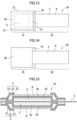
- FIG. 9 demonstrates results of voltage shifts in this event at a temperature of 25 °C, measured using HJ1001SD8 manufactured by HOKUTO DENKO CORP.
- FIG. 10 demonstrates results of discharge and charge tests on a lithium-air battery not having the configuration of the present invention.
- FIG. 8 illustrates the structure of an anode composite 101 in the lithium-air battery used in the tests in FIG. 10 .
- a separator 107 does not seal an anode layer 105 on an anode current collector 103.
- FIG. 10 demonstrate that the lithium-air battery illustrated in FIG. 8 not employing the configuration of the present invention stopped discharging after 23 cycles of charge and discharge.
- a PP (polypropylene) resin was used for the resin layer 21, an Al (aluminum) foil for the metallic foil layer 22, and a PET (polyethylene terephthalate) resin for the resin layer 23.
- a 2 ⁇ 2-cm rectangular piece in the center portion of the metallic foil laminated film 2 was punched out to provide the opening 4.
- the 2.5 ⁇ 2.5 cm rectangular solid electrolyte 8 (LATP) was stacked onto the lower side of the metallic foil laminated film 2 to plug the opening 4. With an adhesive sheet interposed therebetween, the four sides of the solid electrolyte 8 were heat-sealed to the metallic foil laminated film 2 using a heat sealer.
- the anode 30 (see FIG. 2 ) was fabricated inside a glove box under an argon atmosphere.
- the anode current collector 3 having an acid-modified polypropylene film joined to its back surface was prepared (copper foil thickness: 10 ⁇ m, current collector size: 1.4 ⁇ 10 cm).
- metallic lithium (with a size of 1.45 ⁇ 1.4 cm and a thickness of 200 ⁇ m) was stacked.
- the conductive electron-conducting layer 10 was formed on the inner side of the separator 7 by Au vapor deposition, and the single separator 7 was folded near its center to wrap the current collecting portion 31.
- one folded part and the other folded part of the separator 7 were heat-sealed to each other at the joined portions 73, which correspond to three sides of each of the folded parts: both end portions that are to stick out from the anode current collector 3 and an end portion where the anode current collector 3 is to be inserted.
- the separator 7 was thus formed into a bag and covered the current collecting portion 31.
- the anode 30 was thus integrally formed (see FIGs. 13 and 14 ).
- the upper metallic foil laminated film 2, the anode 30, and the lower metallic foil laminated film 2 were stacked so that the solid electrolyte 8 may coincide with the anode layer 5 on the anode current collector 3.
- three sides out of their peripheral portions were heat-sealed using a heat sealer.
- 1 ml of a non-aqueous electrolytic solution (4MLiFSI/EGDME in this example) was injected into the anode composite. Thereafter, the unsealed edge portion (the part with the tab of the anode current collector 3) was joined by a heat sealer.
- the anode composite 1d in FIG. 11 was thus fabricated. Note that the anode current collector 3 and the upper and lower jacket materials were heat-sealed with heat-seal sheets being interposed therebetween.
- LATP LICGC manufactured by OHARA INC.
- a separator for lithium-ion batteries one made of a polyethylene resin and having a thickness of 25 ⁇ m, an average pore size of 0.03 ⁇ m or below, a porosity of 44%, and an air permeance of 450 sec/100 cc was used.
- the metallic foil in the triple-layer metallic foil laminated film 2 used in this example an SUS foil or a copper foil may be used instead of Al.
- the outermost resin film of the metallic foil laminated film 2 is desirably a polyester resin film, such as a PET resin, having high thermal resistance and strength, or a nylon resin film.
- the innermost layer is desirably polyolefin resins such as a PE resin or a PP resin, which have low melting points, high hot workability, and high suitability for heat sealing.
- a metallic foil laminate film having four or more layers may be used which additionally includes one or more resin films such as nylon films between those three layers.
- the cathode (not shown) was fabricated.
- 0.8 g of MnO 2 as a cathode catalyst, 0.1 g of Ketjenblack (specific surface area 800m 2 /g) as a conductivity aid, and 0.1 g of polytetrafluoroethylene (PTFE) as a binder were prepared. Then, they were mixed and kneaded in an agate mortar after 5 ml of ethanol was added as a dispersant. A cathode material was thus made.
- this cathode material was divided into two parts, which were then placed on respective surfaces of a Ti mesh pressure-bonded part integrally having a 2.5 ⁇ 2.5-cm2 pressure-bonded part and a 1 ⁇ 5.5-cm2 tab portion and were pressed with a force of 20 kN to be pressure bonded. Then, the above was let dry naturally in air for 24 hours. The cathode structure was thus fabricated.
- the anode composite 1d and the cathode were disposed facing each other, to fabricate a lithium-air battery.
- a mixture of LiOH and LiCl adjusted to pH of 10 or below was used as an aqueous electrolyte for the cathode.
- 1.5 ml of the LiOH solution was dropped onto a 3 ⁇ 3-cm polyacrylamide sheet, which was then placed between the anode composite 1d and the cathode.
- the comparative example is basically the same as the anode composite 1d of Example 2, but uses a separator 7 which is not made to be conductive.
- An anode composite of the comparative example is configured as follows.
- An integrated anode of the comparative example was fabricated as follows in a glove box under an argon atmosphere.
- a metallic lithium anode layer (with a size of 1.45 ⁇ 1.4 cm and a thickness of 200 ⁇ m) was joined to the front surface of a copper foil which was an anode current collector (the copper foil thickness: 10 ⁇ m, the current collector size: 1.4 ⁇ 10 cm) having an integral terminal and having an acid-modified polypropylene film joined to the back surface thereof.
- a separator for lithium ion batteries was bent near its center, and its peripheral three sides were heat-sealed to make the separator bag-shaped. With the bag-shaped separator covering the anode layer and part of the anode current collector, the separator was heat-sealed to an end portion of the current collector at positions slightly outward of the copper foil.
- the upper jacket material, the integrated anode, a metallic foil laminated film (one without the solid electrolyte opening) as a lower jacket material were stacked with the solid electrolyte portion and the anode surface facing each other, and the three sides at the end portions were heat-sealed using a heat sealer.
- 1 ml of a non-aqueous electrolyte (4M (mol/l) LiFSI/EGDME) was injected into the anode composite from the unsealed end portion.
- the one last unsealed end portion was sealed using a heat sealer in an airtight manner.
- the anode composite of the comparative example was thus fabricated.
- the anode current collector and the upper and lower jacket materials were heat-sealed with heat-sealing sheets made of an acid-modified PP resin or the like interposed.
- a method for fabricating a cathode, a method for fabricating an air battery, and a method for charge and discharge tests are the same as those used in Example 2.
Landscapes
- Chemical & Material Sciences (AREA)
- Chemical Kinetics & Catalysis (AREA)
- Electrochemistry (AREA)
- General Chemical & Material Sciences (AREA)
- Engineering & Computer Science (AREA)
- Materials Engineering (AREA)
- Manufacturing & Machinery (AREA)
- Hybrid Cells (AREA)
- Cell Separators (AREA)
- Cell Electrode Carriers And Collectors (AREA)
Claims (3)
- Anodenverbundstruktur (1d, 1e, 1f) für eine Lithium-Luft-Batterie, umfassend:einen Festelektrolyten (8), unter dem eine Anode (30) angeordnet ist;einen Anodenstromabnehmer (3);eine Anodenschicht (5), die auf den Anodenstromabnehmer (3) gestapelt ist, wobei die Anodenschicht (5) metallisches Lithium, eine Lithium als Hauptbestandteil enthaltende Legierung oder eine Lithium als Hauptbestandteil enthaltende chemische Verbindung ist, wobei die Anodenschicht (5) auf eine Oberfläche des Anodenstromabnehmers (3) über einen Bereich gestapelt ist, der kleiner ist als eine Fläche des Anodenstromabnehmers (3), und von dem Festelektrolyten (8) getrennt ist und mit diesem nicht in direktem Kontakt steht; undeinen Separator (7b), der auf die Anodenschicht (5) gestapelt ist, wobei die Anodenschicht (5) durch den Separator (7b) und den Anodenstromabnehmer (3) eingeschlossen ist;dadurch gekennzeichnet, dassdie Anodenverbundstruktur (1d, 1e, 1f) eine elektronenleitende Schicht (10) auf einer Innenseite des Separators (7b) umfasst.
- Anodenverbundstruktur (1d, 1e, 1f) für eine Lithium-Luft-Batterie nach Anspruch 1, wobei
der Separator (7b) mit dem Anodenstromabnehmer (3) um einen peripheren Abschnitt der Anodenschicht (5) herum verbunden ist. - Anodenverbundstruktur (1d, 1e, 1f) für eine Lithium-Luft-Batterie nach Anspruch 1 oder 2, wobeider Anodenstromabnehmer (3) plattenförmig ist,die Anodenschicht (5) auf einer der Oberflächen des Anodenstromabnehmers (3) angeordnet ist; unddie andere der Oberflächen des Anodenstromabnehmers (3) mit einer Substanz bedeckt ist, die Lithiumionen nicht leitet.
Priority Applications (1)
| Application Number | Priority Date | Filing Date | Title |
|---|---|---|---|
| EP19185508.9A EP3588605B1 (de) | 2016-04-25 | 2017-03-31 | Anodenverbundstruktur für lithium-luft-batterie |
Applications Claiming Priority (2)
| Application Number | Priority Date | Filing Date | Title |
|---|---|---|---|
| JP2016087103 | 2016-04-25 | ||
| PCT/JP2017/013610 WO2017187888A1 (ja) | 2016-04-25 | 2017-03-31 | リチウム空気電池の負極複合体構造 |
Related Child Applications (2)
| Application Number | Title | Priority Date | Filing Date |
|---|---|---|---|
| EP19185508.9A Division EP3588605B1 (de) | 2016-04-25 | 2017-03-31 | Anodenverbundstruktur für lithium-luft-batterie |
| EP19185508.9A Division-Into EP3588605B1 (de) | 2016-04-25 | 2017-03-31 | Anodenverbundstruktur für lithium-luft-batterie |
Publications (3)
| Publication Number | Publication Date |
|---|---|
| EP3451439A1 EP3451439A1 (de) | 2019-03-06 |
| EP3451439A4 EP3451439A4 (de) | 2019-04-03 |
| EP3451439B1 true EP3451439B1 (de) | 2025-02-12 |
Family
ID=60161601
Family Applications (2)
| Application Number | Title | Priority Date | Filing Date |
|---|---|---|---|
| EP19185508.9A Active EP3588605B1 (de) | 2016-04-25 | 2017-03-31 | Anodenverbundstruktur für lithium-luft-batterie |
| EP17789176.9A Active EP3451439B1 (de) | 2016-04-25 | 2017-03-31 | Komposit-anode struktur für lithium-luft-batterie |
Family Applications Before (1)
| Application Number | Title | Priority Date | Filing Date |
|---|---|---|---|
| EP19185508.9A Active EP3588605B1 (de) | 2016-04-25 | 2017-03-31 | Anodenverbundstruktur für lithium-luft-batterie |
Country Status (5)
| Country | Link |
|---|---|
| US (1) | US10622691B2 (de) |
| EP (2) | EP3588605B1 (de) |
| JP (1) | JP6960909B2 (de) |
| CN (1) | CN109075413B (de) |
| WO (1) | WO2017187888A1 (de) |
Families Citing this family (6)
| Publication number | Priority date | Publication date | Assignee | Title |
|---|---|---|---|---|
| JP6962070B2 (ja) | 2017-08-29 | 2021-11-05 | スズキ株式会社 | 空気電池およびそれに用いる負極複合体 |
| JP7091965B2 (ja) * | 2018-09-14 | 2022-06-28 | スズキ株式会社 | 空気電池およびそれに用いる負極複合体 |
| JP7299995B2 (ja) * | 2019-10-25 | 2023-06-28 | シャープ株式会社 | ラミネート電池およびその製造方法 |
| JP7401071B2 (ja) * | 2019-11-05 | 2023-12-19 | スズキ株式会社 | 金属空気電池 |
| JP7317877B2 (ja) * | 2021-02-09 | 2023-07-31 | プライムプラネットエナジー&ソリューションズ株式会社 | 非水電解液二次電池 |
| WO2025191748A1 (ja) * | 2024-03-13 | 2025-09-18 | 日本碍子株式会社 | 酸素供給デバイス |
Citations (1)
| Publication number | Priority date | Publication date | Assignee | Title |
|---|---|---|---|---|
| US20140162108A1 (en) * | 2005-08-09 | 2014-06-12 | Polyplus Battery Company | Lithium battery with hermetically sealed anode |
Family Cites Families (17)
| Publication number | Priority date | Publication date | Assignee | Title |
|---|---|---|---|---|
| JPS6220263A (ja) | 1985-07-18 | 1987-01-28 | Hitachi Maxell Ltd | 薄型リチウム電池 |
| JPH05325948A (ja) | 1992-05-27 | 1993-12-10 | Osaka Gas Co Ltd | 負極材の製造方法およびリチウム二次電池 |
| US9368775B2 (en) * | 2004-02-06 | 2016-06-14 | Polyplus Battery Company | Protected lithium electrodes having porous ceramic separators, including an integrated structure of porous and dense Li ion conducting garnet solid electrolyte layers |
| BRPI0614743A2 (pt) * | 2005-08-09 | 2011-04-12 | Polyplus Battery Co Inc | estruturas de vedação flexìveis para ánodos de metal ativos protegidos |
| US8404388B2 (en) * | 2005-08-09 | 2013-03-26 | Polyplus Battery Company | Compliant seal structures for protected active metal anodes |
| JP4633864B2 (ja) | 2008-06-25 | 2011-02-16 | パナソニック株式会社 | 蓄電材料および蓄電デバイス |
| JP2010161059A (ja) * | 2008-12-09 | 2010-07-22 | Panasonic Corp | 非水電解質二次電池用負極活物質、非水電解質二次電池用負極および非水電解質二次電池 |
| JP5382573B2 (ja) | 2009-02-19 | 2014-01-08 | 国立大学法人三重大学 | リチウム空気電池 |
| JP5721329B2 (ja) | 2010-01-18 | 2015-05-20 | 住友化学株式会社 | 空気電池、空気電池スタック |
| CN101752627B (zh) * | 2010-01-20 | 2012-06-06 | 中国科学院上海微系统与信息技术研究所 | 一种高能量密度金属锂-空气电池及其制作方法 |
| US9076251B2 (en) | 2010-08-04 | 2015-07-07 | Xerox Corporation | Component specific image modification using natural language color |
| US8722256B2 (en) * | 2010-10-20 | 2014-05-13 | Ut-Battelle, Llc | Multi-layered, chemically bonded lithium-ion and lithium/air batteries |
| JP2013157289A (ja) | 2012-01-31 | 2013-08-15 | Sumitomo Chemical Co Ltd | 電極触媒の構造体の製造方法、電極触媒の構造体、膜電極ガス拡散層接合体、燃料電池および空気電池 |
| KR101561188B1 (ko) * | 2013-02-20 | 2015-10-16 | 에스케이이노베이션 주식회사 | 리튬 이차전지용 음극, 그 제조방법 및 이를 포함하는 리튬 에어 배터리 |
| JP6260870B2 (ja) | 2014-06-18 | 2018-01-17 | スズキ株式会社 | 金属空気電池 |
| JP6361963B2 (ja) | 2014-06-20 | 2018-07-25 | スズキ株式会社 | リチウム空気電池の負極複合体、リチウム空気電池、およびリチウム空気電池モジュール |
| JP2016046039A (ja) | 2014-08-21 | 2016-04-04 | スズキ株式会社 | 金属空気電池およびその正極側用の電解媒体 |
-
2017
- 2017-03-31 US US16/086,531 patent/US10622691B2/en active Active
- 2017-03-31 EP EP19185508.9A patent/EP3588605B1/de active Active
- 2017-03-31 CN CN201780025429.8A patent/CN109075413B/zh active Active
- 2017-03-31 EP EP17789176.9A patent/EP3451439B1/de active Active
- 2017-03-31 WO PCT/JP2017/013610 patent/WO2017187888A1/ja not_active Ceased
- 2017-03-31 JP JP2018514216A patent/JP6960909B2/ja active Active
Patent Citations (1)
| Publication number | Priority date | Publication date | Assignee | Title |
|---|---|---|---|---|
| US20140162108A1 (en) * | 2005-08-09 | 2014-06-12 | Polyplus Battery Company | Lithium battery with hermetically sealed anode |
Also Published As
| Publication number | Publication date |
|---|---|
| EP3451439A4 (de) | 2019-04-03 |
| EP3588605A1 (de) | 2020-01-01 |
| EP3451439A1 (de) | 2019-03-06 |
| WO2017187888A1 (ja) | 2017-11-02 |
| JP6960909B2 (ja) | 2021-11-05 |
| EP3588605B1 (de) | 2025-02-12 |
| CN109075413B (zh) | 2021-05-07 |
| CN109075413A (zh) | 2018-12-21 |
| US10622691B2 (en) | 2020-04-14 |
| JPWO2017187888A1 (ja) | 2019-02-21 |
| US20190103642A1 (en) | 2019-04-04 |
Similar Documents
| Publication | Publication Date | Title |
|---|---|---|
| EP3588605B1 (de) | Anodenverbundstruktur für lithium-luft-batterie | |
| KR101776885B1 (ko) | 둘 이상의 케이스 부재들을 포함하는 각형 전지셀 | |
| JP5664783B2 (ja) | 電池モジュール | |
| US20140017577A1 (en) | Air electrode for metal-air battery and metal air battery | |
| US10784503B2 (en) | Protected lithium electrode structure for lithium-air battery | |
| KR20170068730A (ko) | 가스 흡착제가 포함되어 있는 전극 리드를 구비한 전지셀 | |
| JP6995194B2 (ja) | 非水電解質二次電池 | |
| JP5609829B2 (ja) | 空気電池 | |
| US10680301B2 (en) | Metal-air battery and protected lithium electrode used therein | |
| JP5589980B2 (ja) | 金属空気電池 | |
| JP6583138B2 (ja) | 金属空気電池 | |
| JP7131214B2 (ja) | 金属空気電池 | |
| JP5601289B2 (ja) | 空気電池 | |
| JP7091965B2 (ja) | 空気電池およびそれに用いる負極複合体 | |
| JP2020009609A (ja) | 空気電池、空気電池システム及びそれに用いる正極構造体 | |
| JP6665729B2 (ja) | リチウム空気電池の正極構造 | |
| JP7598550B2 (ja) | リチウム金属電池の負極複合体 | |
| KR102576174B1 (ko) | 전해질 보존형 아연 공기전지 | |
| JP2020038793A (ja) | 金属空気電池 | |
| CN112020790A (zh) | 非水电解质二次电池 |
Legal Events
| Date | Code | Title | Description |
|---|---|---|---|
| STAA | Information on the status of an ep patent application or granted ep patent |
Free format text: STATUS: THE INTERNATIONAL PUBLICATION HAS BEEN MADE |
|
| PUAI | Public reference made under article 153(3) epc to a published international application that has entered the european phase |
Free format text: ORIGINAL CODE: 0009012 |
|
| STAA | Information on the status of an ep patent application or granted ep patent |
Free format text: STATUS: REQUEST FOR EXAMINATION WAS MADE |
|
| 17P | Request for examination filed |
Effective date: 20181018 |
|
| AK | Designated contracting states |
Kind code of ref document: A1 Designated state(s): AL AT BE BG CH CY CZ DE DK EE ES FI FR GB GR HR HU IE IS IT LI LT LU LV MC MK MT NL NO PL PT RO RS SE SI SK SM TR |
|
| AX | Request for extension of the european patent |
Extension state: BA ME |
|
| A4 | Supplementary search report drawn up and despatched |
Effective date: 20190301 |
|
| RIC1 | Information provided on ipc code assigned before grant |
Ipc: H01M 4/40 20060101ALI20190225BHEP Ipc: H01M 12/08 20060101ALN20190225BHEP Ipc: H01M 4/134 20100101ALI20190225BHEP Ipc: H01M 4/70 20060101ALI20190225BHEP Ipc: H01M 2/02 20060101AFI20190225BHEP Ipc: H01M 12/06 20060101ALN20190225BHEP Ipc: H01M 4/38 20060101ALI20190225BHEP Ipc: H01M 2/16 20060101ALI20190225BHEP |
|
| DAV | Request for validation of the european patent (deleted) | ||
| DAX | Request for extension of the european patent (deleted) | ||
| STAA | Information on the status of an ep patent application or granted ep patent |
Free format text: STATUS: EXAMINATION IS IN PROGRESS |
|
| 17Q | First examination report despatched |
Effective date: 20191010 |
|
| RIN1 | Information on inventor provided before grant (corrected) |
Inventor name: MINAMI, HIRONARI Inventor name: RAHMAN, KHALILUR Inventor name: IZUMI, HIROAKI Inventor name: NOMURA, MASAYA |
|
| RIN1 | Information on inventor provided before grant (corrected) |
Inventor name: IZUMI, HIROAKI Inventor name: MINAMI, HIRONARI Inventor name: NOMURA, MASAYA Inventor name: RAHMAN, KHALILUR |
|
| REG | Reference to a national code |
Ref country code: DE Ref legal event code: R079 Free format text: PREVIOUS MAIN CLASS: H01M0012080000 Ipc: H01M0004380000 Ref country code: DE Ref legal event code: R079 Ref document number: 602017087716 Country of ref document: DE Free format text: PREVIOUS MAIN CLASS: H01M0012080000 Ipc: H01M0004380000 |
|
| GRAP | Despatch of communication of intention to grant a patent |
Free format text: ORIGINAL CODE: EPIDOSNIGR1 |
|
| STAA | Information on the status of an ep patent application or granted ep patent |
Free format text: STATUS: GRANT OF PATENT IS INTENDED |
|
| RIC1 | Information provided on ipc code assigned before grant |
Ipc: H01M 4/02 20060101ALN20241031BHEP Ipc: H01M 12/08 20060101ALN20241031BHEP Ipc: H01M 12/06 20060101ALN20241031BHEP Ipc: H01M 50/138 20210101ALI20241031BHEP Ipc: H01M 50/466 20210101ALI20241031BHEP Ipc: H01M 50/46 20210101ALI20241031BHEP Ipc: H01M 4/134 20100101ALI20241031BHEP Ipc: H01M 4/70 20060101ALI20241031BHEP Ipc: H01M 4/40 20060101ALI20241031BHEP Ipc: H01M 4/38 20060101AFI20241031BHEP |
|
| GRAS | Grant fee paid |
Free format text: ORIGINAL CODE: EPIDOSNIGR3 |
|
| INTG | Intention to grant announced |
Effective date: 20241202 |
|
| GRAA | (expected) grant |
Free format text: ORIGINAL CODE: 0009210 |
|
| STAA | Information on the status of an ep patent application or granted ep patent |
Free format text: STATUS: THE PATENT HAS BEEN GRANTED |
|
| AK | Designated contracting states |
Kind code of ref document: B1 Designated state(s): AL AT BE BG CH CY CZ DE DK EE ES FI FR GB GR HR HU IE IS IT LI LT LU LV MC MK MT NL NO PL PT RO RS SE SI SK SM TR |
|
| REG | Reference to a national code |
Ref country code: GB Ref legal event code: FG4D |
|
| REG | Reference to a national code |
Ref country code: CH Ref legal event code: EP |
|
| REG | Reference to a national code |
Ref country code: DE Ref legal event code: R096 Ref document number: 602017087716 Country of ref document: DE |
|
| REG | Reference to a national code |
Ref country code: IE Ref legal event code: FG4D |
|
| REG | Reference to a national code |
Ref country code: NL Ref legal event code: MP Effective date: 20250212 |
|
| PG25 | Lapsed in a contracting state [announced via postgrant information from national office to epo] |
Ref country code: RS Free format text: LAPSE BECAUSE OF FAILURE TO SUBMIT A TRANSLATION OF THE DESCRIPTION OR TO PAY THE FEE WITHIN THE PRESCRIBED TIME-LIMIT Effective date: 20250512 |
|
| PG25 | Lapsed in a contracting state [announced via postgrant information from national office to epo] |
Ref country code: FI Free format text: LAPSE BECAUSE OF FAILURE TO SUBMIT A TRANSLATION OF THE DESCRIPTION OR TO PAY THE FEE WITHIN THE PRESCRIBED TIME-LIMIT Effective date: 20250212 |
|
| PG25 | Lapsed in a contracting state [announced via postgrant information from national office to epo] |
Ref country code: PL Free format text: LAPSE BECAUSE OF FAILURE TO SUBMIT A TRANSLATION OF THE DESCRIPTION OR TO PAY THE FEE WITHIN THE PRESCRIBED TIME-LIMIT Effective date: 20250212 |
|
| PG25 | Lapsed in a contracting state [announced via postgrant information from national office to epo] |
Ref country code: ES Free format text: LAPSE BECAUSE OF FAILURE TO SUBMIT A TRANSLATION OF THE DESCRIPTION OR TO PAY THE FEE WITHIN THE PRESCRIBED TIME-LIMIT Effective date: 20250212 |
|
| REG | Reference to a national code |
Ref country code: LT Ref legal event code: MG9D |
|
| PG25 | Lapsed in a contracting state [announced via postgrant information from national office to epo] |
Ref country code: IS Free format text: LAPSE BECAUSE OF FAILURE TO SUBMIT A TRANSLATION OF THE DESCRIPTION OR TO PAY THE FEE WITHIN THE PRESCRIBED TIME-LIMIT Effective date: 20250612 Ref country code: NO Free format text: LAPSE BECAUSE OF FAILURE TO SUBMIT A TRANSLATION OF THE DESCRIPTION OR TO PAY THE FEE WITHIN THE PRESCRIBED TIME-LIMIT Effective date: 20250512 |
|
| PG25 | Lapsed in a contracting state [announced via postgrant information from national office to epo] |
Ref country code: NL Free format text: LAPSE BECAUSE OF FAILURE TO SUBMIT A TRANSLATION OF THE DESCRIPTION OR TO PAY THE FEE WITHIN THE PRESCRIBED TIME-LIMIT Effective date: 20250212 |
|
| PG25 | Lapsed in a contracting state [announced via postgrant information from national office to epo] |
Ref country code: HR Free format text: LAPSE BECAUSE OF FAILURE TO SUBMIT A TRANSLATION OF THE DESCRIPTION OR TO PAY THE FEE WITHIN THE PRESCRIBED TIME-LIMIT Effective date: 20250212 |
|
| PG25 | Lapsed in a contracting state [announced via postgrant information from national office to epo] |
Ref country code: PT Free format text: LAPSE BECAUSE OF FAILURE TO SUBMIT A TRANSLATION OF THE DESCRIPTION OR TO PAY THE FEE WITHIN THE PRESCRIBED TIME-LIMIT Effective date: 20250612 Ref country code: LV Free format text: LAPSE BECAUSE OF FAILURE TO SUBMIT A TRANSLATION OF THE DESCRIPTION OR TO PAY THE FEE WITHIN THE PRESCRIBED TIME-LIMIT Effective date: 20250212 |
|
| PG25 | Lapsed in a contracting state [announced via postgrant information from national office to epo] |
Ref country code: GR Free format text: LAPSE BECAUSE OF FAILURE TO SUBMIT A TRANSLATION OF THE DESCRIPTION OR TO PAY THE FEE WITHIN THE PRESCRIBED TIME-LIMIT Effective date: 20250513 Ref country code: BG Free format text: LAPSE BECAUSE OF FAILURE TO SUBMIT A TRANSLATION OF THE DESCRIPTION OR TO PAY THE FEE WITHIN THE PRESCRIBED TIME-LIMIT Effective date: 20250212 |
|
| REG | Reference to a national code |
Ref country code: AT Ref legal event code: MK05 Ref document number: 1766974 Country of ref document: AT Kind code of ref document: T Effective date: 20250212 |
|
| PG25 | Lapsed in a contracting state [announced via postgrant information from national office to epo] |
Ref country code: SE Free format text: LAPSE BECAUSE OF FAILURE TO SUBMIT A TRANSLATION OF THE DESCRIPTION OR TO PAY THE FEE WITHIN THE PRESCRIBED TIME-LIMIT Effective date: 20250212 |
|
| PG25 | Lapsed in a contracting state [announced via postgrant information from national office to epo] |
Ref country code: SM Free format text: LAPSE BECAUSE OF FAILURE TO SUBMIT A TRANSLATION OF THE DESCRIPTION OR TO PAY THE FEE WITHIN THE PRESCRIBED TIME-LIMIT Effective date: 20250212 |
|
| PG25 | Lapsed in a contracting state [announced via postgrant information from national office to epo] |
Ref country code: DK Free format text: LAPSE BECAUSE OF FAILURE TO SUBMIT A TRANSLATION OF THE DESCRIPTION OR TO PAY THE FEE WITHIN THE PRESCRIBED TIME-LIMIT Effective date: 20250212 |
|
| PG25 | Lapsed in a contracting state [announced via postgrant information from national office to epo] |
Ref country code: IT Free format text: LAPSE BECAUSE OF FAILURE TO SUBMIT A TRANSLATION OF THE DESCRIPTION OR TO PAY THE FEE WITHIN THE PRESCRIBED TIME-LIMIT Effective date: 20250212 |
|
| PG25 | Lapsed in a contracting state [announced via postgrant information from national office to epo] |
Ref country code: AT Free format text: LAPSE BECAUSE OF FAILURE TO SUBMIT A TRANSLATION OF THE DESCRIPTION OR TO PAY THE FEE WITHIN THE PRESCRIBED TIME-LIMIT Effective date: 20250212 |
|
| PG25 | Lapsed in a contracting state [announced via postgrant information from national office to epo] |
Ref country code: EE Free format text: LAPSE BECAUSE OF FAILURE TO SUBMIT A TRANSLATION OF THE DESCRIPTION OR TO PAY THE FEE WITHIN THE PRESCRIBED TIME-LIMIT Effective date: 20250212 Ref country code: CZ Free format text: LAPSE BECAUSE OF FAILURE TO SUBMIT A TRANSLATION OF THE DESCRIPTION OR TO PAY THE FEE WITHIN THE PRESCRIBED TIME-LIMIT Effective date: 20250212 |
|
| PG25 | Lapsed in a contracting state [announced via postgrant information from national office to epo] |
Ref country code: RO Free format text: LAPSE BECAUSE OF FAILURE TO SUBMIT A TRANSLATION OF THE DESCRIPTION OR TO PAY THE FEE WITHIN THE PRESCRIBED TIME-LIMIT Effective date: 20250212 |
|
| REG | Reference to a national code |
Ref country code: CH Ref legal event code: H13 Free format text: ST27 STATUS EVENT CODE: U-0-0-H10-H13 (AS PROVIDED BY THE NATIONAL OFFICE) Effective date: 20251024 |
|
| PG25 | Lapsed in a contracting state [announced via postgrant information from national office to epo] |
Ref country code: SK Free format text: LAPSE BECAUSE OF FAILURE TO SUBMIT A TRANSLATION OF THE DESCRIPTION OR TO PAY THE FEE WITHIN THE PRESCRIBED TIME-LIMIT Effective date: 20250212 |
|
| REG | Reference to a national code |
Ref country code: DE Ref legal event code: R097 Ref document number: 602017087716 Country of ref document: DE |
|
| PG25 | Lapsed in a contracting state [announced via postgrant information from national office to epo] |
Ref country code: LU Free format text: LAPSE BECAUSE OF NON-PAYMENT OF DUE FEES Effective date: 20250331 |
|
| REG | Reference to a national code |
Ref country code: BE Ref legal event code: MM Effective date: 20250331 |
|
| PLBE | No opposition filed within time limit |
Free format text: ORIGINAL CODE: 0009261 |
|
| STAA | Information on the status of an ep patent application or granted ep patent |
Free format text: STATUS: NO OPPOSITION FILED WITHIN TIME LIMIT |
|
| PG25 | Lapsed in a contracting state [announced via postgrant information from national office to epo] |
Ref country code: MC Free format text: LAPSE BECAUSE OF FAILURE TO SUBMIT A TRANSLATION OF THE DESCRIPTION OR TO PAY THE FEE WITHIN THE PRESCRIBED TIME-LIMIT Effective date: 20250212 |
|
| PG25 | Lapsed in a contracting state [announced via postgrant information from national office to epo] |
Ref country code: BE Free format text: LAPSE BECAUSE OF NON-PAYMENT OF DUE FEES Effective date: 20250331 |
|
| PG25 | Lapsed in a contracting state [announced via postgrant information from national office to epo] |
Ref country code: CH Free format text: LAPSE BECAUSE OF NON-PAYMENT OF DUE FEES Effective date: 20250331 |
|
| PG25 | Lapsed in a contracting state [announced via postgrant information from national office to epo] |
Ref country code: IE Free format text: LAPSE BECAUSE OF NON-PAYMENT OF DUE FEES Effective date: 20250331 |
|
| 26N | No opposition filed |
Effective date: 20251113 |
|
| GBPC | Gb: european patent ceased through non-payment of renewal fee |
Effective date: 20250512 |
|
| PG25 | Lapsed in a contracting state [announced via postgrant information from national office to epo] |
Ref country code: GB Free format text: LAPSE BECAUSE OF NON-PAYMENT OF DUE FEES Effective date: 20250512 |
|
| PGFP | Annual fee paid to national office [announced via postgrant information from national office to epo] |
Ref country code: DE Payment date: 20260204 Year of fee payment: 10 |
|
| PGFP | Annual fee paid to national office [announced via postgrant information from national office to epo] |
Ref country code: FR Payment date: 20260209 Year of fee payment: 10 |