EP3450098B1 - Radeckenpoliervorrichtung - Google Patents
Radeckenpoliervorrichtung Download PDFInfo
- Publication number
- EP3450098B1 EP3450098B1 EP18190684.3A EP18190684A EP3450098B1 EP 3450098 B1 EP3450098 B1 EP 3450098B1 EP 18190684 A EP18190684 A EP 18190684A EP 3450098 B1 EP3450098 B1 EP 3450098B1
- Authority
- EP
- European Patent Office
- Prior art keywords
- sliding table
- polishing
- cylinder
- wheel
- guide rail
- Prior art date
- Legal status (The legal status is an assumption and is not a legal conclusion. Google has not performed a legal analysis and makes no representation as to the accuracy of the status listed.)
- Active
Links
Images


Classifications
-
- B—PERFORMING OPERATIONS; TRANSPORTING
- B24—GRINDING; POLISHING
- B24B—MACHINES, DEVICES, OR PROCESSES FOR GRINDING OR POLISHING; DRESSING OR CONDITIONING OF ABRADING SURFACES; FEEDING OF GRINDING, POLISHING, OR LAPPING AGENTS
- B24B5/00—Machines or devices designed for grinding surfaces of revolution on work, including those which also grind adjacent plane surfaces; Accessories therefor
- B24B5/02—Machines or devices designed for grinding surfaces of revolution on work, including those which also grind adjacent plane surfaces; Accessories therefor involving centres or chucks for holding work
- B24B5/12—Machines or devices designed for grinding surfaces of revolution on work, including those which also grind adjacent plane surfaces; Accessories therefor involving centres or chucks for holding work for grinding cylindrical surfaces both externally and internally with several grinding wheels
-
- B—PERFORMING OPERATIONS; TRANSPORTING
- B24—GRINDING; POLISHING
- B24B—MACHINES, DEVICES, OR PROCESSES FOR GRINDING OR POLISHING; DRESSING OR CONDITIONING OF ABRADING SURFACES; FEEDING OF GRINDING, POLISHING, OR LAPPING AGENTS
- B24B27/00—Other grinding machines or devices
- B24B27/0023—Other grinding machines or devices grinding machines with a plurality of working posts
-
- B—PERFORMING OPERATIONS; TRANSPORTING
- B24—GRINDING; POLISHING
- B24B—MACHINES, DEVICES, OR PROCESSES FOR GRINDING OR POLISHING; DRESSING OR CONDITIONING OF ABRADING SURFACES; FEEDING OF GRINDING, POLISHING, OR LAPPING AGENTS
- B24B27/00—Other grinding machines or devices
- B24B27/0069—Other grinding machines or devices with means for feeding the work-pieces to the grinding tool, e.g. turntables, transfer means
-
- B—PERFORMING OPERATIONS; TRANSPORTING
- B24—GRINDING; POLISHING
- B24B—MACHINES, DEVICES, OR PROCESSES FOR GRINDING OR POLISHING; DRESSING OR CONDITIONING OF ABRADING SURFACES; FEEDING OF GRINDING, POLISHING, OR LAPPING AGENTS
- B24B27/00—Other grinding machines or devices
- B24B27/0076—Other grinding machines or devices grinding machines comprising two or more grinding tools
-
- B—PERFORMING OPERATIONS; TRANSPORTING
- B24—GRINDING; POLISHING
- B24B—MACHINES, DEVICES, OR PROCESSES FOR GRINDING OR POLISHING; DRESSING OR CONDITIONING OF ABRADING SURFACES; FEEDING OF GRINDING, POLISHING, OR LAPPING AGENTS
- B24B41/00—Component parts such as frames, beds, carriages, headstocks
- B24B41/005—Feeding or manipulating devices specially adapted to grinding machines
-
- B—PERFORMING OPERATIONS; TRANSPORTING
- B24—GRINDING; POLISHING
- B24B—MACHINES, DEVICES, OR PROCESSES FOR GRINDING OR POLISHING; DRESSING OR CONDITIONING OF ABRADING SURFACES; FEEDING OF GRINDING, POLISHING, OR LAPPING AGENTS
- B24B41/00—Component parts such as frames, beds, carriages, headstocks
- B24B41/02—Frames; Beds; Carriages
-
- B—PERFORMING OPERATIONS; TRANSPORTING
- B24—GRINDING; POLISHING
- B24B—MACHINES, DEVICES, OR PROCESSES FOR GRINDING OR POLISHING; DRESSING OR CONDITIONING OF ABRADING SURFACES; FEEDING OF GRINDING, POLISHING, OR LAPPING AGENTS
- B24B41/00—Component parts such as frames, beds, carriages, headstocks
- B24B41/06—Work supports, e.g. adjustable steadies
- B24B41/067—Work supports, e.g. adjustable steadies radially supporting workpieces
-
- B—PERFORMING OPERATIONS; TRANSPORTING
- B24—GRINDING; POLISHING
- B24B—MACHINES, DEVICES, OR PROCESSES FOR GRINDING OR POLISHING; DRESSING OR CONDITIONING OF ABRADING SURFACES; FEEDING OF GRINDING, POLISHING, OR LAPPING AGENTS
- B24B47/00—Drives or gearings; Equipment therefor
- B24B47/20—Drives or gearings; Equipment therefor relating to feed movement
-
- B—PERFORMING OPERATIONS; TRANSPORTING
- B24—GRINDING; POLISHING
- B24B—MACHINES, DEVICES, OR PROCESSES FOR GRINDING OR POLISHING; DRESSING OR CONDITIONING OF ABRADING SURFACES; FEEDING OF GRINDING, POLISHING, OR LAPPING AGENTS
- B24B49/00—Measuring or gauging equipment for controlling the feed movement of the grinding tool or work; Arrangements of indicating or measuring equipment, e.g. for indicating the start of the grinding operation
- B24B49/12—Measuring or gauging equipment for controlling the feed movement of the grinding tool or work; Arrangements of indicating or measuring equipment, e.g. for indicating the start of the grinding operation involving optical means
-
- B—PERFORMING OPERATIONS; TRANSPORTING
- B24—GRINDING; POLISHING
- B24B—MACHINES, DEVICES, OR PROCESSES FOR GRINDING OR POLISHING; DRESSING OR CONDITIONING OF ABRADING SURFACES; FEEDING OF GRINDING, POLISHING, OR LAPPING AGENTS
- B24B5/00—Machines or devices designed for grinding surfaces of revolution on work, including those which also grind adjacent plane surfaces; Accessories therefor
- B24B5/35—Accessories
-
- B—PERFORMING OPERATIONS; TRANSPORTING
- B24—GRINDING; POLISHING
- B24B—MACHINES, DEVICES, OR PROCESSES FOR GRINDING OR POLISHING; DRESSING OR CONDITIONING OF ABRADING SURFACES; FEEDING OF GRINDING, POLISHING, OR LAPPING AGENTS
- B24B5/00—Machines or devices designed for grinding surfaces of revolution on work, including those which also grind adjacent plane surfaces; Accessories therefor
- B24B5/36—Single-purpose machines or devices
- B24B5/44—Single-purpose machines or devices for grinding rims of vehicle wheels, e.g. for bicycles
-
- B—PERFORMING OPERATIONS; TRANSPORTING
- B24—GRINDING; POLISHING
- B24B—MACHINES, DEVICES, OR PROCESSES FOR GRINDING OR POLISHING; DRESSING OR CONDITIONING OF ABRADING SURFACES; FEEDING OF GRINDING, POLISHING, OR LAPPING AGENTS
- B24B9/00—Machines or devices designed for grinding edges or bevels on work or for removing burrs; Accessories therefor
- B24B9/02—Machines or devices designed for grinding edges or bevels on work or for removing burrs; Accessories therefor characterised by a special design with respect to properties of materials specific to articles to be ground
- B24B9/04—Machines or devices designed for grinding edges or bevels on work or for removing burrs; Accessories therefor characterised by a special design with respect to properties of materials specific to articles to be ground of metal, e.g. skate blades
-
- Y—GENERAL TAGGING OF NEW TECHNOLOGICAL DEVELOPMENTS; GENERAL TAGGING OF CROSS-SECTIONAL TECHNOLOGIES SPANNING OVER SEVERAL SECTIONS OF THE IPC; TECHNICAL SUBJECTS COVERED BY FORMER USPC CROSS-REFERENCE ART COLLECTIONS [XRACs] AND DIGESTS
- Y02—TECHNOLOGIES OR APPLICATIONS FOR MITIGATION OR ADAPTATION AGAINST CLIMATE CHANGE
- Y02P—CLIMATE CHANGE MITIGATION TECHNOLOGIES IN THE PRODUCTION OR PROCESSING OF GOODS
- Y02P70/00—Climate change mitigation technologies in the production process for final industrial or consumer products
- Y02P70/10—Greenhouse gas [GHG] capture, material saving, heat recovery or other energy efficient measures, e.g. motor control, characterised by manufacturing processes, e.g. for rolling metal or metal working
Definitions
- the present invention relates to the technical field of wheel corner polishing, specifically to a device for automatically polishing four positions including bolt hole corners, a valve hole corner, outer rim corners and cap section corners of a wheel.
- Document KR 2016 004 7284 A discloses a wheel corner polishing device, being composed of a rack, an outer rim polishing head and implicitly, a wheel feeding roller bed, a wheel discharge roller bed. This document is concerned about the polishing of the exterior of the wheel including the outer rim.
- the present invention is aimed at providing a wheel corner polishing device, which can meet the requirement of an automatic production line for automatically polishing four positions including bolt hole corners, a valve hole corner, outer rim corners and cap section corners of a wheel.
- a wheel corner polishing device is composed of a rack, a jacking cylinder I, guide posts I, a lifting table I, a guide rail I, an adjusting cylinder I, a sliding table I, a polishing motor I, an outer rim polishing head, a jacking cylinder II, guide posts II, a lifting table II, a guide rail II, an adjusting cylinder II, a sliding table II, a polishing motor II, a cap section polishing head, a station switching motor, a coupling, a bearing seat, a bearing, a station switching table, positioning guide rails, a left sliding table, a right sliding table, a gear rack, a clamping cylinder, drive motors, clamping wheels, a polishing roller bed, a wheel feeding roller bed, a wheel discharge roller bed, a pitch adjusting guide rail, a pitch adjusting sliding table, a pitch adjusting cylinder, a guide rail III, an adjusting cylinder III, a sliding table III, a connecting rod, a turning
- the station switching motor is fixed on the rack, the output end of the station switching motor is connected with the station switching table via the coupling, and the polishing roller bed and four positioning guide rails are mounted on the upper surface of the station switching table.
- the left sliding table and the right sliding table are symmetrically mounted on the positioning guide rails, and are connected via the gear rack.
- the clamping cylinder is fixed on the station switching table, and the output end of the clamping cylinder is connected with the left sliding table.
- Two drive motors are respectively mounted on the left sliding table and the right sliding table, and the clamping wheels are mounted at the output ends of the drive motors.
- the clamping cylinder When a wheel enters the polishing roller bed from the wheel feeding roller bed, the clamping cylinder is started, the left sliding table and the right sliding table move synchronously under the action of the gear rack, and the wheel can be positioned and clamped via the clamping wheels. After the wheel is positioned and clamped on the upper surface of the station switching table, corners of bolt holes and a valve hole are polished, and this is an upper station.
- the structure of the lower surface of the station switching table is symmetric to and completely consistent with that of the upper surface; and after the wheel is positioned and clamped on the lower surface of the station switching table, corners of the outer rim and cap sections are polished, and this is a lower station.
- the station switching motor can control rotation of the station switching table, thus controlling cyclic switching of the upper station and the lower station; after corner polishing of the bolt holes and valve hole of the wheel are completed at the upper station, it is switched to the lower station for corner polishing of the outer rim and cap sections; and after the polishing is completed, the wheel is rotated to the upper station again for transferring down. Corner polishing of the bolt holes and valve hole of the wheel is completed at the upper station, corner polishing of the outer rim and cap sections is completed at the lower station, corner polishing of four positions is completed via switching and coordination of the upper and lower station, and this is a station switching system.
- the pitch adjusting cylinder and the pitch adjusting guide rail are fixed on the rack, the pitch adjusting sliding table is mounted on the pitch adjusting guide rail, and the output end of the pitch adjusting cylinder is connected with the pitch adjusting sliding table to control horizontal movement of the sliding table.
- the adjusting cylinder III and the guide rail III are fixed on the pitch adjusting sliding table, the sliding table III is mounted on the guide rail III, and the output end of the adjusting cylinder III is connected with the sliding table III to control horizontal movement of the sliding table III.
- the turning plate is articulated with the pitch adjusting sliding table, one end of the connecting rod is articulated with the sliding table III, the other end of the connecting rod is articulated with the turning plate, and when the adjusting cylinder III drives the sliding table III to move horizontally, the turning angle of the turning plate can be adjusted.
- the feeding cylinder and the feeding guide rail are fixedly mounted on the turning plate, the feeding sliding table is mounted on the feeding guide rail, the output end of the feeding cylinder is connected with the feeding sliding table, the polishing motor III is fixed on the feeding sliding table, and the valve hole polishing head is mounted at the output end of the polishing motor III.
- the vision sensor is mounted at the bottom of the turning plate and used for recognizing the position of the valve hole, after the wheel is positioned and clamped at the upper station, the drive motors are started, the wheel rotates at a low speed, the valve hole rotating below the vision sensor is recognized, at the moment, the wheel stops rotating, and the valve hole is ready for corner polishing.
- the horizontal position of the valve hole polishing head can be adjusted via the pitch adjusting cylinder, the angle between the valve hole polishing head and the central axis of the wheel can be adjusted via the adjusting cylinder III, the rotating polishing head can be fed for polishing in the direction of the valve hole via the feeding cylinder, and this is a valve hole polishing system.
- the polishing head of this system can be correspondingly adjusted according to the radial position and angle of the valve hole, and can thus be used for corner polishing of different wheel outer diameters and different valve hole angles with wider adaptability.
- the servo motor is fixedly mounted at the top of the rack, and the output end of the servo motor is connected with the rotating table via the shaft to control rotation of the rotating table.
- the support frame is fixed on the rotating table
- the electric cylinder is fixed on the support frame
- the output end of the electric cylinder is connected with the feeding platform to control up-down motion of the feeding platform under the guiding effect of the guide posts.
- the guide rail IV and the adjusting cylinder IV are fixed on the feeding platform
- the sliding table IV is mounted on the guide rail IV
- the output end of the adjusting cylinder IV is connected with the sliding table IV to control horizontal motion thereof.
- the polishing motor IV is mounted on the sliding table IV, and the bolt hole polishing head is mounted at the output end of the polishing motor IV.
- the wheel stops rotating, the first polished bolt hole is determined according to the included angle between the valve hole and the bolt hole, at the moment, the servo motor is started to drive the rotating table to rotate, the bolt hole polishing head is thus driven to rotate around the center of the wheel, the bolt hole polishing head rotates to a position above the first bolt hole that needs to be polished, and then the electric cylinder is started to drive the rotating bolt hole polishing head to be fed down to polish the corner.
- the electric cylinder drives the bolt hole polishing head to move up and reset, then the servo motor continuously drives the bolt hole polishing head to rotate around the center of the wheel, the bolt hole polishing head rotates to a position above the second bolt hole according to the included angle between the bolt holes, the polishing begins, all bolt holes are polished in sequence, and this is a bolt hole polishing system.
- the horizontal position of the polishing head can be adjusted via the adjusting cylinder VI, thus, this system can polish wheel bolt holes having different pitch diameters, the servo motor can drive the polishing head to rotate degrees around the center of the wheel, thus, this system can be used for polishing wheels having different bolt holes.
- the jacking cylinder I is fixed on a cross beam at the bottom of the rack, and the output end of the jacking cylinder I is connected with the lifting table I to control ascending and descending of the lifting table I under the guiding effect of the four guide posts I.
- the adjusting cylinder I and the guide rail I are fixed on the lifting table I, the sliding table I is mounted on the guide rail I, the output end of the adjusting cylinder I is connected with the sliding table I to control horizontal motion thereof, the polishing motor I is mounted on the sliding table I, the outer rim polishing head is mounted at the output end of the polishing motor I, and feeding of the outer rim polishing head can be controlled via the jacking cylinder I .
- the jacking cylinder II is fixed on the cross beam at the bottom of the rack, and the output end of the jacking cylinder II is connected with the lifting table II to control ascending and descending of the lifting table II under the guiding effect of the four guide posts II.
- the adjusting cylinder II and the guide rail II are fixed on the lifting table II, the sliding table II is mounted on the guide rail II, the output end of the adjusting cylinder II is connected with the sliding table II to control horizontal motion thereof, the polishing motor II is mounted on the sliding table II, the cap section polishing head is mounted at the output end of the polishing motor II, and feeding of the cap section polishing head can be controlled via the jacking cylinder II .
- the wheel is switched to the lower station via the station switching system, at the moment, the wheel begins rotating at a low speed under drive of the drive motors, the jacking cylinder I drives the outer rim polishing head to be fed to polish the outer rim of the wheel, and the jacking cylinder II drives the cap section polishing head to be fed to polish the cap sections of the wheel. From the beginning of polishing to one-circle rotation of the wheel, the whole outer rim and the cap sections are completely polished, and this is a rim and cap section synchronous polishing system.
- the horizontal position of the outer rim polishing head can be adjusted via the adjusting cylinder I, and the horizontal position of the cap section polishing head can be adjusted via the adjusting cylinder II, so this system can polish wheels having different outer diameters and different cap section sizes.
- the working process of the device is: first, according to the outer diameter, cap section size, valve hole angle and bolt hole pitch diameter of a wheel produced on line, the initial positions of the outer rim polishing head, the cap section polishing head, the valve hole polishing head and the bolt hole polishing head are adjusted.
- the clamping cylinder When the wheel enters the polishing roller bed from the wheel feeding roller bed, the clamping cylinder is started, and the wheel is positioned and clamped; next, the drive motors are started to drive the wheel to rotate at a low speed, and when the vision sensor recognizes the position of the valve hole, the wheel stops rotating; then, the valve hole polishing head is fed to polish the corner of the valve hole, the bolt hole polishing head rotates to a position above the first bolt hole and polishes the corner of the bolt hole, after the first bolt hole is polished, the servo motor drives the rotating table to rotate, the bolt hole polishing head rotates to a position above the second bolt hole, and the corners of the bolt holes are polished in sequence, till all the bolt holes are polished; next, the station switching motor is started, the wheel at the upper station rotates to the lower station and continuously undergoes corner polishing of the outer rim and cap sections, and the positioning device idle at the lower station rotates to the upper station for positioning and polishing of next wheel.
- the device is in a full-load state, the corners of the valve hole and bolt holes of the wheel are polished at the upper station, the corners of the outer rim and cap sections are polished at the lower station, and all the corner polishing time is effectively shortened via reasonable design of the upper and lower stations, so the cycle is short and the efficiency is high.
- the station switching motor is restarted to switch the wheel at the upper or lower station, at the moment, corner polishing at four positions has been completed for the wheel at the upper station, the wheel is loosened and fed into the wheel discharge roller bed, the upper station continuously receives next wheel to be polished, and so on.
- the present invention can meet the requirement of an automatic production line, and can automatically polish four positions including bolt hole corners, a valve hole corner, outer rim corners and cap section corners of a wheel via reasonable process layout, upper and lower stations and coordination of the systems, so that the minimum fillets of the four positions meet the requirements.
- the device has the characteristics of short cycle, high efficiency, skillful design, strong generality, easy manufacture and the like.
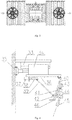
- a wheel corner polishing device is composed of a rack 1, a jacking cylinder I 2, guide posts I 3, a lifting table I 4, a guide rail I 5, an adjusting cylinder I 6, a sliding table 17, a polishing motor I 8, an outer rim polishing head 9, a jacking cylinder II 10, guide posts II 11, a lifting table II 12, a guide rail II 13, an adjusting cylinder II 14, a sliding table II 15, a polishing motor II 16, a cap section polishing head 17, a station switching motor 18, a coupling 19, a bearing seat 20, a bearing 21, a station switching table 22, positioning guide rails 23, a left sliding table 24, a right sliding table 25, a gear rack 26, a clamping cylinder 27, drive motors 28, clamping wheels 29, a polishing roller bed 30, a wheel feeding roller bed 31, a wheel discharge roller bed 32, a pitch adjusting guide rail 33, a pitch adjusting sliding table 34, a pitch adjusting cylinder 35, a guide rail III 36, an adjusting cylinder III 37, a sliding table III 38, a
- the station switching motor 18 is fixed on the rack 1, the output end of the station switching motor 18 is connected with the station switching table 22 via the coupling 19, and the polishing roller bed 30 and four positioning guide rails 23 are mounted on the upper surface of the station switching table 22.
- the left sliding table 24 and the right sliding table 25 are symmetrically mounted on the positioning guide rails 23, and are connected via the gear rack 26.
- the clamping cylinder 27 is fixed on the station switching table 22, and the output end of the clamping cylinder 27 is connected with the left sliding table24.
- Two drive motors 28 are respectively mounted on the left sliding table 24 and the right sliding table 25, and the clamping wheels 29 are mounted at the output ends of the drive motors 28.
- the clamping cylinder 27 When a wheel enters the polishing roller bed 30 from the wheel feeding roller bed 31, the clamping cylinder 27 is started, the left sliding table 24 and the right sliding table 25 move synchronously under the action of the gear rack 26, and the wheel can be positioned and clamped via the clamping wheels 29.
- the wheel After the wheel is positioned and clamped on the upper surface of the station switching table 22, corners of bolt holes and a valve hole are polished, and this is an upper station.
- the structure of the lower surface of the station switching table 22 is symmetric to and completely consistent with that of the upper surface; and after the wheel is positioned and clamped on the lower surface of the station switching table 22, corners of the outer rim and cap sections are polished, and this is a lower station.
- the station switching motor 18 can control rotation of the station switching table 22, thus controlling cyclic switching of the upper station and the lower station; after corner polishing of the bolt holes and valve hole of the wheel are completed at the upper station, it is switched to the lower station for corner polishing of the outer rim and cap sections; and after the polishing is completed, the wheel is rotated to the upper station again for transferring down. Corner polishing of the bolt holes and valve hole of the wheel is completed at the upper station, corner polishing of the outer rim and cap sections is completed at the lower station, corner polishing of four positions is completed via switching and coordination of the upper and lower station, and this is a station switching system.
- the pitch adjusting cylinder 35 and the pitch adjusting guide rail 33 are fixed on the rack 1, the pitch adjusting sliding table 34 is mounted on the pitch adjusting guide rail 33, and the output end of the pitch adjusting cylinder 35 is connected with the pitch adjusting sliding table 34 to control horizontal movement of the sliding table.
- the adjusting cylinder III 37 and the guide rail III 36 are fixed on the pitch adjusting sliding table 34, the sliding table III 38 is mounted on the guide rail III 36, and the output end of the adjusting cylinder III 37 is connected with the sliding table III 38 to control horizontal movement of the sliding table III 38.
- the turning plate 40 is articulated with the pitch adjusting sliding table 34, one end of the connecting rod 39 is articulated with the sliding table III 38, the other end of the connecting rod 39 is articulated with the turning plate 40, and when the adjusting cylinder III 37 drives the sliding table III 38 to move horizontally, the turning angle of the turning plate 40 can be adjusted.
- the feeding cylinder 43 and the feeding guide rail 41 are fixedly mounted on the turning plate 40, the feeding sliding table 42 is mounted on the feeding guide rail 41, the output end of the feeding cylinder 43 is connected with the feeding sliding table 42, the polishing motor III 44 is fixed on the feeding sliding table 42, and the valve hole polishing head 45 is mounted at the output end of the polishing motor III 44.
- the vision sensor 46 is mounted at the bottom of the turning plate 40 and used for recognizing the position of the valve hole, after the wheel is positioned and clamped at the upper station, the drive motors 28 are started, the wheel rotates at a low speed, the valve hole rotating below the vision sensor 46 is recognized, at the moment, the wheel stops rotating, and the valve hole is ready for corner polishing.
- the horizontal position of the valve hole polishing head 45 can be adjusted via the pitch adjusting cylinder 35, the angle between the valve hole polishing head 45 and the central axis of the wheel can be adjusted via the adjusting cylinder III 37, the rotating polishing head can be fed for polishing in the direction of the valve hole via the feeding cylinder 43, and this is a valve hole polishing system.
- the polishing head of this system can be correspondingly adjusted according to the radial position and angle of the valve hole, and can thus be used for corner polishing of different wheel outer diameters and different valve hole angles with wider adaptability.
- the servo motor 47 is fixedly mounted at the top of the rack 1, and the output end of the servo motor 47 is connected with the rotating table 49 via the shaft 48 to control rotation of the rotating table 49.
- the support frame 51 is fixed on the rotating table 49
- the electric cylinder 50 is fixed on the support frame 51
- the output end of the electric cylinder 50 is connected with the feeding platform 53 to control up-down motion of the feeding platform 53 under the guiding effect of the guide posts 52.
- the guide rail IV 54 and the adjusting cylinder IV 56 are fixed on the feeding platform 53
- the sliding table IV 55 is mounted on the guide rail IV 54
- the output end of the adjusting cylinder IV 56 is connected with the sliding table IV 55 to control horizontal motion thereof.
- the polishing motor IV 57 is mounted on the sliding table IV 55, and the bolt hole polishing head 58 is mounted at the output end of the polishing motor IV 57.
- the first polished bolt hole is determined according to the included angle between the valve hole and the bolt hole, at the moment, the servo motor 47 is started to drive the rotating table 49 to rotate, the bolt hole polishing head 58 is thus driven to rotate around the center of the wheel, the bolt hole polishing head 58 rotates to a position above the first bolt hole that needs to be polished, and then the electric cylinder 50 is started to drive the rotating bolt hole polishing head 58 to be fed down to polish the corner.
- the electric cylinder 50 drives the bolt hole polishing head 58 to move up and reset, then the servo motor 47 continuously drives the bolt hole polishing head 58 to rotate around the center of the wheel, the bolt hole polishing head 58 rotates to a position above the second bolt hole according to the included angle between the bolt holes, the polishing begins, all bolt holes are polished in sequence, and this is a bolt hole polishing system.
- the horizontal position of the polishing head can be adjusted via the adjusting cylinder IV 56, thus, this system can polish wheel bolt holes having different pitch diameters, the servo motor 47 can drive the polishing head to rotate 360 degrees around the center of the wheel, thus, this system can be used for polishing wheels having different bolt holes.
- the jacking cylinder I 2 is fixed on a cross beam at the bottom of the rack 1, and the output end of the jacking cylinder I 2 is connected with the lifting table 14 to control ascending and descending of the lifting table I 4 under the guiding effect of the four guide posts 13.
- the adjusting cylinder I 6 and the guide rail I 5 are fixed on the lifting table I 4, the sliding table I 7 is mounted on the guide rail I 5, the output end of the adjusting cylinder I 6 is connected with the sliding table 17 to control horizontal motion thereof, the polishing motor I 8 is mounted on the sliding table I 7, the outer rim polishing head 9 is mounted at the output end of the polishing motor I 8, and feeding of the outer rim polishing head 9 can be controlled via the jacking cylinder I 2.
- the jacking cylinder II 10 is fixed on the cross beam at the bottom of the rack 1, and the output end of the jacking cylinder II 10 is connected with the lifting table II 12 to control ascending and descending of the lifting table II 12 under the guiding effect of the four guide posts II 11.
- the adjusting cylinder II 14 and the guide rail II 13 are fixed on the lifting table II 12
- the sliding table II 15 is mounted on the guide rail II 13
- the output end of the adjusting cylinder II 14 is connected with the sliding table II 15 to control horizontal motion thereof
- the polishing motor II 16 is mounted on the sliding table II
- the cap section polishing head 17 is mounted at the output end of the polishing motor II 16, and feeding of the cap section polishing head 17 can be controlled via the jacking cylinder II 10.
- the wheel is switched to the lower station via the station switching system, at the moment, the wheel begins rotating at a low speed under drive of the drive motors 28, the jacking cylinder I 2 drives the outer rim polishing head 9 to be fed to polish the outer rim of the wheel, and the jacking cylinder II 10 drives the cap section polishing head 17 to be fed to polish the cap sections of the wheel.
- the whole outer rim and the cap sections are completely polished, and this is a rim and cap section synchronous polishing system.
- the horizontal position of the outer rim polishing head 9 can be adjusted via the adjusting cylinder I 6, and the horizontal position of the cap section polishing head 17 can be adjusted via the adjusting cylinder II 14, so this system can polish wheels having different outer diameters and different cap section sizes.
- the working process of the device is: first, according to the outer diameter, cap section size, valve hole angle and bolt hole pitch diameter of a wheel produced on line, the initial positions of the outer rim polishing head 9, the cap section polishing head 17, the valve hole polishing head 45 and the bolt hole polishing head 58 are adjusted.
- the clamping cylinder 27 When the wheel enters the polishing roller bed 30 from the wheel feeding roller bed 31, the clamping cylinder 27 is started, and the wheel is positioned and clamped; next, the drive motors 28 are started to drive the wheel to rotate at a low speed, and when the vision sensor 46 recognizes the position of the valve hole, the wheel stops rotating; then, the valve hole polishing head 45 is fed to polish the corner of the valve hole, the bolt hole polishing head 58 rotates to a position above the first bolt hole and polishes the corner of the bolt hole, after the first bolt hole is polished, the servo motor 47 drives the rotating table 49 to rotate, the bolt hole polishing head 58 rotates to a position above the second bolt hole, and the corners of the bolt holes are polished in sequence, till all the bolt holes are polished; next, the station switching motor 18 is started, the wheel at the upper station rotates to the lower station and continuously undergoes corner polishing of the outer rim and cap sections, and the positioning device idle at the lower station rotates to the upper station for positioning and
- the device is in a full-load state, the corners of the valve hole and bolt holes of the wheel are polished at the upper station, the corners of the outer rim and cap sections are polished at the lower station, and all the corner polishing time is effectively shortened via reasonable design of the upper and lower stations, so the cycle is short and the efficiency is high.
- the station switching motor 18 is restarted to switch the wheel at the upper or lower station, at the moment, corner polishing at four positions has been completed for the wheel at the upper station, the wheel is loosened and fed into the wheel discharge roller bed 32, the upper station continuously receives next wheel to be polished, and so on.
- the present invention can meet the requirement of an automatic production line, and can automatically polish four positions including bolt hole corners, a valve hole corner, outer rim corners and cap section corners of a wheel via reasonable process layout, upper and lower stations and coordination of the systems, so that the minimum fillets of the four positions meet the requirements.
- the device has the characteristics of short cycle, high efficiency, skillful design, strong generality, easy manufacture and the like.
Landscapes
- Engineering & Computer Science (AREA)
- Mechanical Engineering (AREA)
- Grinding And Polishing Of Tertiary Curved Surfaces And Surfaces With Complex Shapes (AREA)
- Grinding Of Cylindrical And Plane Surfaces (AREA)
Claims (1)
- Poliervorrichtung für Radecken, bestehend aus einem Gestell (1), einem Hubzylinder I (2), Führungspfosten I (3), einem Hubtisch I (4), einer Führungsschiene I (5) und einem Einstellzylinder I (6), einem Schiebetisch I (7), einem Poliermotor I (8), einem Außenrandpolierkopf (9), einem Hebezylinder II (10), Führungspfosten II (11), einem Hubtisch II (12), einer Führungsschiene II (13), einem Einstellzylinder II (14), einem Schiebetisch II (15), einem Poliermotor II (16), einem Kappenabschnitt-Polierkopf (17), einem Stationsschaltmotor (18), einer Kupplung (19), einem Lagersitz (20), einem Lager (21), einem Stationsschalttisch (22), Positionierungsführungsschienen (23), einem linken Schiebetisch (24), einem rechten Schiebetisch (25), einer Zahnstange (26), einem Spannzylinder (27), Antriebsmotoren (28), Klemmräder (29), einem Polierwalzenbett (30), einem Radvorschubwalzenbett (31), einem Radausgabewalzenbett (32), einer Pitch-Einstellführungsschiene (33), einem Pitch-Einstellschiebetisch (34), einem Pitch-Einstellzylinder (35), einer Führungsschiene III (36), einem Einstellzapfen III (37), einem Schiebetisch III (38), einer Pleuelstange (39), einer Drehplatte (40), einer Zuführführungsschiene (41), einem Zuführschiebetisch (42), einem Zuführzylinder (43), einem Poliermotor III (44), einem Ventillochpolierkopf (45), einem Sichtsensor (46), einem Servomotor (47), einer Welle (48), einem Drehtisch (49), einem elektrischen Zylinder (50), einem Stützrahmen (51), Führungspfosten (52), einer Zuführplattform (53), einer Führungsschiene IV (54), einem Schiebetisch IV (55), einem Einstellzylinder IV (56), einem Poliermotor IV (57) und einem Bolzenloch-Polierkopf (58),
wobei der Stationsschaltmotor (18) an dem Gestell (1) befestigt ist, wobei das Ausgangsende des Stationsschaltmotors (18) über die Kupplung (19) mit dem Stationsschalttisch (22) verbunden ist, und das Polierwalzenbett (30) und vier Positionierungsführungsschienen (23) an der Oberseite des Stationsschalttisches (22) angebracht sind; wobei der linke Schiebetisch (24) und der rechte Schiebetisch (25) symmetrisch auf den Positionierführungsschienen (23) montiert und über die Zahnstange (26) verbunden sind; wobei der Spannzylinder (27) am Stationsschalttisch (22) befestigt ist, und das Ausgangsende des Spannzylinders (27) mit dem linken Schiebetisch (24) verbunden ist; wobei zwei Antriebsmotoren (28) jeweils auf dem linken Schiebetisch (24) und dem rechten Schiebetisch (25) montiert sind, und die Klemmräder (29) an den Ausgangsenden der Antriebsmotoren (28) montiert sind; wobei nachdem das Rad auf der Oberseite des Stationsschalttisches (22) positioniert und festgeklemmt ist, werden die Ecken der Schraubenlöcher und ein Ventilloch poliert, und dies ist eine obere Station; nachdem das Rad auf der Unterseite des Stationsschalttisches (22) positioniert und festgeklemmt ist, werden die Ecken des Außenrands und der Kappenabschnitte poliert, und dies ist eine untere Station; wobei das Eckpolieren von vier Positionen durch Umschalten und Koordinieren der oberen und unteren Station abgeschlossen wird;
wobei der Pitch-Einstellzylinder (35) und die Pitch-Einstellführungsschiene (33) an dem Gestell (1) befestigt sind, wobei der Pitch-Einstellschiebetisch (34) an der Pitch-Einstellführungsschiene (33) montiert ist und das Ausgangsende des Pitch-Einstellzylinders (35) mit dem Pitch-Einstellschiebetisch (34) verbunden ist, um die horizontale Bewegung des Schiebetisches zu steuern; wobei der Einstellzylinder III (37) und die Führungsschiene III (36) am Pitch-Einstellschiebetisch (34) befestigt sind, wobei der Schiebetisch III (38) auf der Führungsschiene III (36) montiert ist und das Ausgangsende des Einstellzylinders III (37) mit dem Schiebetisch III (38) verbunden ist, um die horizontale Bewegung des Schiebetisches III (38) zu steuern; wobei die Drehplatte (40) mit dem Pitch-Einstellschiebetisch (34) angelenkt ist, ein Ende der Pleuelstange (39) mit dem Schiebetisch III (38) gelenkig verbunden ist und das andere Ende der Pleuelstange (39) mit der Drehplatte (40) gelenkig verbunden ist, und wobei wenn der Einstellzylinder III (37) den Schiebetisch III (38) antreibt, um sich horizontal zu bewegen, kann der Drehwinkel der Drehplatte (40) eingestellt werden; wobei der Zuführzylinder (43) und die Zuführführungsschiene (41) fest auf der Drehplatte (40) montiert sind, der Zuführschiebetisch (42) auf der Zuführführungsschiene (41) montiert ist, wobei das Ausgangsende des Zuführzylinders (43) mit dem Zuführschiebetisch (42) verbunden ist, wobei der Poliermotor III (44) am Zuführschiebetisch (42) befestigt ist und der Ventillochpolierkopf (45) am Ausgangsende des Poliermotors III (44) angebracht ist; wobei der Sichtsensor (46) an der Unterseite der Drehplatte (40) angebracht ist;
wobei der Servomotor (47) fest an der Oberseite des Gestells (1) montiert ist, und das Ausgangsende des Servomotors (47) über die Welle (48) mit dem Drehtisch (49) verbunden ist, um die Drehung des Drehtisches (49) zu steuern; wobei der Stützrahmen (51) am Drehtisch (49) befestigt ist, der elektrische Zylinder (50) am Stützrahmen (51) befestigt ist und das Ausgangsende des elektrischen Zylinders (50) mit der Zuführplattform (53) verbunden ist, zum Steuern der Auf- und Ab-Bewegung der Zuführplattform (53) unter der Führungswirkung der Führungspfosten (52); wobei die Führungsschiene IV (54) und der Einstellzylinder IV (56) an der Zuführplattform (53) befestigt sind, der Schiebetisch IV (55) an der Führungsschiene IV (54) montiert ist und das Ausgangsende der Einstellzylinder IV (56) mit dem Schiebetisch IV (55) verbunden ist, um dessen horizontale Bewegung zu steuern, wobei der Poliermotor IV (57) auf dem Schiebetisch IV (55) montiert ist, und der Bolzenloch-Polierkopf (58) am Ausgangsende des Poliermotors IV (57) montiert ist; wobei nachdem das Ventilloch des Rades vom Sichtsensor (46) erkannt wurde, hört das Rad auf, sich zu drehen, und das erste polierte Bolzenloch wird gemäß dem eingeschlossenen Winkel zwischen dem Ventilloch und dem Bolzenloch bestimmt, im Moment, der Servomotor (47) wird gestartet, um den Drehtisch (49) zum Drehen anzutreiben, der Bolzenloch-Polierkopf (58) wird somit angetrieben, um sich um die Mitte des Rades zu drehen; der Bolzenloch-Polierkopf (58) dreht sich in eine Position über dem ersten Bolzenloch, die poliert werden soll, und dann wird der elektrische Zylinder (50) gestartet, um den rotierenden Bolzenloch-Polierkopf (58) anzutreiben, so dass der Bolzenloch-Polierkopf zum Polieren der Ecke nach unten geführt wird; wobei nachdem die Ecke des ersten Schraubenlochs poliert ist, treibt der elektrische Zylinder (50) den Schraubenlochpolierkopf (58) an, um sich nach oben zu bewegen und zurückzusetzen, und dann treibt der Servomotor (47) den Schraubenlochpolierkopf (58) kontinuierlich an, um um die Radmitte zu drehen, dreht sich der Bolzenloch-Polierkopf (58) in eine Position über dem zweiten Bolzenloch entsprechend dem eingeschlossenen Winkel zwischen den Bolzenlöchern, das Polieren beginnt, alle Bolzenlöcher werden nacheinander poliert, und das ist ein Bolzenloch-Poliersystem;
wobei der Hubzylinder I (2) an einem Querträger am Boden des Gestells (1) befestigt ist, und das Ausgangsende des Hubzylinders I (2) mit dem Hubtisch I (4) verbunden ist, um das Auf- und Absteigen des Hubtisches I (4) unter der Führungswirkung der vier Führungspfosten I (3) zu steuern; wobei der Einstellzylinder I (6) und die Führungsschiene I (5) am Hubtisch I (4) befestigt sind, wobei der Schiebetisch I (7) an der Führungsschiene I (5) montiert ist, das Ausgangsende der Einstellzylinder I (6) mit dem Schiebetisch I (7) verbunden ist, um dessen horizontale Bewegung zu steuern, wobei der Poliermotor I (8) auf dem Schiebetisch I (7) montiert ist, wobei der Außenrandpolierkopf (9) an dem Ausgangsende des Poliermotors I (8) montiert ist und die Zuführung des Außenrandpolierkopfes (9) über den Hubzylinder I (2) gesteuert werden kann; wobei der Hubzylinder II (10) am Querträger am Boden der Gestell (1) befestigt ist, und das Ausgangsende des Hubzylinders II (10) mit dem Hubtisch II (12) verbunden ist, um das Auf- und Absteigen des Hubtisches II (12) unter der Führungswirkung der vier Führungspfosten II (11) zu steuern; wobei der Einstellzylinder II (14) und die Führungsschiene II (13) am Hubtisch II (12) befestigt sind, wobei der Schiebetisch II (15) an der Führungsschiene II (13) montiert ist, das Ausgangsende des Einstellzylinders II (14) mit dem Schiebetisch II (15) verbunden ist, um dessen horizontale Bewegung zu steuern; wobei der Poliermotor II (16) auf dem Schiebetisch II (15) montiert ist, der Kappenabschnitt-Polierkopf (17) an dem Ausgangsende des Poliermotors II (16) montiert ist, und die Zuführung des Kappenabschnitt-Polierkopfes (17) über den Hubzylinder II (10) gesteuert werden kann; wobei nachdem das Ventilloch und die Bolzenlöcher des Rades an der oberen Station poliert wurden, wird das Rad über das Stationsschaltsystem zur unteren Station geschaltet, im Moment, beginnt sich das Rad unter Antrieb der Antriebsmotoren (28) mit niedriger Geschwindigkeit zu drehen, treibt der Hubzylinder I (2) den zu zuführenden Außenrandpolierkopf (9) an, um den Außenrand des Rades zu polieren, und der Hubzylinder II (10) treibt den zu zuführenden Kappenabschnitt-Polierkopf (17) an, um die Kappenabschnitte des Rades zu polieren; und vom Beginn des Polierens bis zur Drehung des Rades um einen Kreis sind der gesamte Außenrand und die Kappenabschnitte vollständig poliert, und dies ist ein synchrones Poliersystem für Felge und Kappenabschnitte.
Applications Claiming Priority (1)
| Application Number | Priority Date | Filing Date | Title |
|---|---|---|---|
| CN201710763269.9A CN107350944B (zh) | 2017-08-30 | 2017-08-30 | 一种车轮边角打磨装置 |
Publications (2)
| Publication Number | Publication Date |
|---|---|
| EP3450098A1 EP3450098A1 (de) | 2019-03-06 |
| EP3450098B1 true EP3450098B1 (de) | 2020-05-13 |
Family
ID=60288550
Family Applications (1)
| Application Number | Title | Priority Date | Filing Date |
|---|---|---|---|
| EP18190684.3A Active EP3450098B1 (de) | 2017-08-30 | 2018-08-24 | Radeckenpoliervorrichtung |
Country Status (4)
| Country | Link |
|---|---|
| US (1) | US10513004B2 (de) |
| EP (1) | EP3450098B1 (de) |
| CN (1) | CN107350944B (de) |
| MA (1) | MA44571B1 (de) |
Families Citing this family (28)
| Publication number | Priority date | Publication date | Assignee | Title |
|---|---|---|---|---|
| CN108528018B (zh) * | 2018-05-24 | 2023-10-24 | 中信戴卡股份有限公司 | 一种车轮压印标识装置 |
| CN108637854A (zh) | 2018-05-24 | 2018-10-12 | 中信戴卡股份有限公司 | 一种车轮外轮辋凹槽打磨装置 |
| CN109382724B (zh) * | 2018-11-16 | 2023-12-08 | 浙江连通家居用品股份有限公司 | 一种板材砂边机 |
| CN109822139B (zh) * | 2019-03-26 | 2023-09-08 | 中信戴卡股份有限公司 | 一种用于去除车轮毛坯飞边的装置 |
| CN109968120A (zh) * | 2019-04-26 | 2019-07-05 | 广东万丰摩轮有限公司 | 车轮的高效打磨设备及控制方法 |
| CN110116345A (zh) * | 2019-04-26 | 2019-08-13 | 广东万丰摩轮有限公司 | 车轮的自动打磨设备 |
| CN110640222A (zh) * | 2019-10-23 | 2020-01-03 | 中信戴卡股份有限公司 | 一种在线加工车轮倒角的自动化装置 |
| CN111070084A (zh) * | 2019-12-31 | 2020-04-28 | 浙江芯晖装备技术有限公司 | 一种抛光转盘驱动装置 |
| CN111421415A (zh) * | 2020-05-15 | 2020-07-17 | 博罗县园洲镇鑫泉机械五金铸造有限公司 | 铸铁柱体打磨设备 |
| CN111496653B (zh) * | 2020-05-31 | 2025-04-25 | 浙江天晟建材股份有限公司 | 一种叠合板模具清扫机 |
| CN113635204B (zh) * | 2021-09-01 | 2024-01-26 | 平湖祥和铰链有限公司 | 一种铰链的正反面抛光装置 |
| CN113953949A (zh) * | 2021-11-22 | 2022-01-21 | 苏州科技大学 | 一种机械制造设计用微型打磨装置 |
| CN114147295A (zh) * | 2021-12-15 | 2022-03-08 | 天津那诺机械制造有限公司 | 一种全自动在线铝合金轮毂毛边去除设备 |
| CN114434162B (zh) * | 2022-03-04 | 2024-03-15 | 东莞金源五金机械有限公司 | 用于航天航空激光导航高精密金属件的生产工艺及设备 |
| CN115026692A (zh) * | 2022-03-07 | 2022-09-09 | 安徽工程大学 | 一种用于产品设计的产品外形修塑装置 |
| CN114770244B (zh) * | 2022-05-07 | 2024-08-09 | 厦门创云精智机械设备股份有限公司 | 一种高灵活性数控外圆磨床 |
| CN114833403A (zh) * | 2022-06-28 | 2022-08-02 | 江苏诺嘉机械有限公司 | 一种具有角度和深度可控的压花辊精准打磨设备 |
| CN115122237B (zh) * | 2022-07-13 | 2024-09-20 | 重庆市诚润机械有限公司 | 一种齿毂加工用夹具 |
| CN117226430A (zh) * | 2023-09-12 | 2023-12-15 | 科佳(长兴)模架制造有限公司 | 一种高效打磨抛光模具钢的加工工艺 |
| CN117260454A (zh) * | 2023-10-08 | 2023-12-22 | 浙江巨峰钻饰有限公司 | 一种水晶磨抛机及其加工工艺 |
| CN117381639B (zh) * | 2023-12-11 | 2024-02-13 | 磐吉奥(湖南)铸造工业有限公司 | 一种压铸件成型用联动式内外抛光设备 |
| CN117400090B (zh) * | 2023-12-15 | 2024-03-01 | 淄博职业学院 | 一种管件加工磨削装置 |
| CN117564863B (zh) * | 2024-01-15 | 2024-03-15 | 福建恒通卫浴有限公司 | 一种阀门制造设备及制造工艺 |
| CN117564920B (zh) * | 2024-01-16 | 2024-03-26 | 无锡艾利诺科技有限公司 | 一种轮毂用抛光设备及方法 |
| CN117564209B (zh) * | 2024-01-17 | 2024-03-19 | 江苏锋拓精锻科技有限公司 | 一种锻造冲压组合模具 |
| CN117863023B (zh) * | 2024-02-27 | 2024-08-06 | 唐山市汉沽管理区东方弘叶家具制造有限公司 | 一种木材打磨装置及其使用方法 |
| CN119188563A (zh) * | 2024-08-15 | 2024-12-27 | 昆山佐昵斯科技有限公司 | 一种红外仪前盖加工用抛光装置 |
| CN119319494A (zh) * | 2024-12-19 | 2025-01-17 | 靖江市君之源机械制造有限公司 | 一种精密圆柱螺纹销轴加工的送料机构 |
Family Cites Families (23)
| Publication number | Priority date | Publication date | Assignee | Title |
|---|---|---|---|---|
| GB667407A (en) * | 1949-04-14 | 1952-02-27 | Pierre Lyotard Ets | Machine for polishing convex surfaces in particular the rims of bicycle, tandem bicycle and the like vehicle wheels |
| US3258804A (en) * | 1965-06-01 | 1966-07-05 | Dura Bond Bearing Company | Centerless finishing machine |
| GB1601414A (en) * | 1977-06-04 | 1981-10-28 | Schmidt R | Deburring apparatus |
| US5134807A (en) * | 1986-10-27 | 1992-08-04 | Speedfam Corporation | Multilevel grinding apparatus |
| US5161281A (en) * | 1990-08-14 | 1992-11-10 | Hanen Harry I | Wheel rim cleaning apparatus |
| NO178292C (no) * | 1993-12-14 | 1996-02-28 | Grobi As | Kantsliper for maskinell avrunding av kanter på konstruksjonselementer |
| JP3091417B2 (ja) * | 1996-09-25 | 2000-09-25 | 鬼怒川ゴム工業株式会社 | 円筒型防振体のバリ取り装置 |
| JP3044289B2 (ja) * | 1997-03-13 | 2000-05-22 | 株式会社河村鉄工所 | バリ取り装置 |
| JP3044289U (ja) * | 1997-06-11 | 1997-12-16 | 株式会社日本ロックサービス | 簡易補助錠 |
| JP3091417U (ja) * | 2002-06-15 | 2003-01-31 | 俊鑑 頼 | 三輪騎馬車の五角形車輪及び鈴付ブロックタイヤ |
| JP4320665B2 (ja) * | 2005-08-09 | 2009-08-26 | 株式会社ワーク | 2ピースホイールのメッキ除去装置 |
| JP4079180B2 (ja) * | 2005-08-22 | 2008-04-23 | 株式会社ワーク | 3ピースホイールのメッキ除去装置 |
| KR101188842B1 (ko) * | 2011-10-24 | 2012-10-08 | 한국항공우주산업 주식회사 | 디버링 장치 |
| CN202357023U (zh) * | 2011-11-28 | 2012-08-01 | 苏竞 | 一种冷轧铝合金轮辋抛光机 |
| CN103072057B (zh) | 2012-11-14 | 2015-05-27 | 中信戴卡股份有限公司 | 一种车轮摆动去毛刺装置 |
| CN103447913B (zh) * | 2013-09-02 | 2016-06-22 | 江苏天宏机械科技有限公司 | 铝合金轮毂去毛刺机的恒压自动补偿系统 |
| CN203600007U (zh) | 2013-12-20 | 2014-05-21 | 中信戴卡股份有限公司 | 车轮在线去毛刺装置 |
| KR101715172B1 (ko) * | 2014-10-22 | 2017-03-10 | (주) 진양기계 | 휠 연마용 브러쉬 조절장치 |
| CN105458856B (zh) | 2015-12-29 | 2017-06-30 | 中信戴卡股份有限公司 | 一种旋转式车轮去毛刺装置 |
| CN105598776B (zh) * | 2016-01-23 | 2017-09-29 | 中信戴卡股份有限公司 | 一种尺寸可调的自适应式车轮在线去毛刺装置 |
| CN105881139B (zh) * | 2016-06-01 | 2018-03-20 | 中信戴卡股份有限公司 | 一种车轮背腔去毛刺装置 |
| CN106624927A (zh) * | 2017-01-18 | 2017-05-10 | 中信戴卡股份有限公司 | 一种车轮夹具 |
| CN107030561B (zh) * | 2017-05-19 | 2018-10-02 | 中信戴卡股份有限公司 | 一种多工位式车轮去毛刺装置 |
-
2017
- 2017-08-30 CN CN201710763269.9A patent/CN107350944B/zh active Active
- 2017-11-02 US US15/801,427 patent/US10513004B2/en active Active
-
2018
- 2018-08-24 MA MA44571A patent/MA44571B1/fr unknown
- 2018-08-24 EP EP18190684.3A patent/EP3450098B1/de active Active
Non-Patent Citations (1)
| Title |
|---|
| None * |
Also Published As
| Publication number | Publication date |
|---|---|
| CN107350944A (zh) | 2017-11-17 |
| CN107350944B (zh) | 2023-08-15 |
| EP3450098A1 (de) | 2019-03-06 |
| US20190061089A1 (en) | 2019-02-28 |
| US10513004B2 (en) | 2019-12-24 |
| MA44571B1 (fr) | 2020-07-29 |
Similar Documents
| Publication | Publication Date | Title |
|---|---|---|
| EP3450098A1 (de) | Radeckenpoliervorrichtung | |
| CN104044206B (zh) | 带翻转机构的成型装置 | |
| CN108655476A (zh) | 一种修整车轮毛坯定位端面的装置 | |
| CN201931163U (zh) | 具有角度调整功能的带锯机 | |
| EP3479937A1 (de) | Vorrichtung zur korrektur eines aluminiumlegierungsrads | |
| CN107322062A (zh) | 一种风动铣车轮帽口毛刺装置 | |
| CN113245927B (zh) | 一种十字轴加工用无心磨床自动上下料装置 | |
| CN114571299A (zh) | 一种轧辊表面打磨系统的打磨工艺 | |
| CN108240783A (zh) | 一种舱段对接调整机构 | |
| CN112338639B (zh) | 基于金属加工定位机器人的定位方法 | |
| CN205074903U (zh) | 回转体抛光生产线用弧边抛光装置 | |
| CN102672862A (zh) | 轮胎后充气装置 | |
| CN106311922A (zh) | 一种新型冲压机器人 | |
| CN206869596U (zh) | 一种带有加工模板的玻璃边缘多功能磨削装置 | |
| CN117283381A (zh) | 一种轴心准确的数控圆柱件打磨机 | |
| CN205363483U (zh) | 龙门架式石材线条机 | |
| CN105881469A (zh) | 一种多工位多功能的装载机构 | |
| CN208483290U (zh) | 一种修整车轮毛坯定位端面的装置 | |
| CN202388358U (zh) | 一种自动抛光机 | |
| CN203973741U (zh) | 带翻转机构的成型装置 | |
| CN102059614B (zh) | 带换向装置的水晶磨抛机 | |
| CN215616910U (zh) | 一种十字轴加工用无心磨床自动上下料装置 | |
| CN217914527U (zh) | 一种锻件自动打磨抛光装置 | |
| CN213163651U (zh) | 用于汽车安全气囊袋切割的激光打标机 | |
| CN210307070U (zh) | 一种铸件平面打磨装置 |
Legal Events
| Date | Code | Title | Description |
|---|---|---|---|
| PUAI | Public reference made under article 153(3) epc to a published international application that has entered the european phase |
Free format text: ORIGINAL CODE: 0009012 |
|
| STAA | Information on the status of an ep patent application or granted ep patent |
Free format text: STATUS: REQUEST FOR EXAMINATION WAS MADE |
|
| 17P | Request for examination filed |
Effective date: 20180824 |
|
| AK | Designated contracting states |
Kind code of ref document: A1 Designated state(s): AL AT BE BG CH CY CZ DE DK EE ES FI FR GB GR HR HU IE IS IT LI LT LU LV MC MK MT NL NO PL PT RO RS SE SI SK SM TR |
|
| AX | Request for extension of the european patent |
Extension state: BA ME |
|
| REG | Reference to a national code |
Ref country code: DE Ref legal event code: R079 Ref document number: 602018004498 Country of ref document: DE Free format text: PREVIOUS MAIN CLASS: B24B0005440000 Ipc: B24B0027000000 |
|
| GRAP | Despatch of communication of intention to grant a patent |
Free format text: ORIGINAL CODE: EPIDOSNIGR1 |
|
| STAA | Information on the status of an ep patent application or granted ep patent |
Free format text: STATUS: GRANT OF PATENT IS INTENDED |
|
| RIC1 | Information provided on ipc code assigned before grant |
Ipc: B24B 9/04 20060101ALI20191115BHEP Ipc: B24B 5/35 20060101ALI20191115BHEP Ipc: B24B 41/06 20120101ALI20191115BHEP Ipc: B24B 27/00 20060101AFI20191115BHEP Ipc: B24B 41/00 20060101ALI20191115BHEP Ipc: B24B 5/44 20060101ALI20191115BHEP Ipc: B24B 49/12 20060101ALI20191115BHEP Ipc: B24B 5/12 20060101ALI20191115BHEP |
|
| INTG | Intention to grant announced |
Effective date: 20191217 |
|
| GRAS | Grant fee paid |
Free format text: ORIGINAL CODE: EPIDOSNIGR3 |
|
| GRAA | (expected) grant |
Free format text: ORIGINAL CODE: 0009210 |
|
| STAA | Information on the status of an ep patent application or granted ep patent |
Free format text: STATUS: THE PATENT HAS BEEN GRANTED |
|
| AK | Designated contracting states |
Kind code of ref document: B1 Designated state(s): AL AT BE BG CH CY CZ DE DK EE ES FI FR GB GR HR HU IE IS IT LI LT LU LV MC MK MT NL NO PL PT RO RS SE SI SK SM TR |
|
| REG | Reference to a national code |
Ref country code: GB Ref legal event code: FG4D |
|
| REG | Reference to a national code |
Ref country code: CH Ref legal event code: EP |
|
| REG | Reference to a national code |
Ref country code: DE Ref legal event code: R096 Ref document number: 602018004498 Country of ref document: DE |
|
| REG | Reference to a national code |
Ref country code: AT Ref legal event code: REF Ref document number: 1269636 Country of ref document: AT Kind code of ref document: T Effective date: 20200615 |
|
| REG | Reference to a national code |
Ref country code: MA Ref legal event code: VAGR Ref document number: 44571 Country of ref document: MA Kind code of ref document: B1 |
|
| REG | Reference to a national code |
Ref country code: LT Ref legal event code: MG4D |
|
| REG | Reference to a national code |
Ref country code: NL Ref legal event code: MP Effective date: 20200513 |
|
| PG25 | Lapsed in a contracting state [announced via postgrant information from national office to epo] |
Ref country code: SE Free format text: LAPSE BECAUSE OF FAILURE TO SUBMIT A TRANSLATION OF THE DESCRIPTION OR TO PAY THE FEE WITHIN THE PRESCRIBED TIME-LIMIT Effective date: 20200513 Ref country code: PT Free format text: LAPSE BECAUSE OF FAILURE TO SUBMIT A TRANSLATION OF THE DESCRIPTION OR TO PAY THE FEE WITHIN THE PRESCRIBED TIME-LIMIT Effective date: 20200914 Ref country code: FI Free format text: LAPSE BECAUSE OF FAILURE TO SUBMIT A TRANSLATION OF THE DESCRIPTION OR TO PAY THE FEE WITHIN THE PRESCRIBED TIME-LIMIT Effective date: 20200513 Ref country code: IS Free format text: LAPSE BECAUSE OF FAILURE TO SUBMIT A TRANSLATION OF THE DESCRIPTION OR TO PAY THE FEE WITHIN THE PRESCRIBED TIME-LIMIT Effective date: 20200913 Ref country code: NO Free format text: LAPSE BECAUSE OF FAILURE TO SUBMIT A TRANSLATION OF THE DESCRIPTION OR TO PAY THE FEE WITHIN THE PRESCRIBED TIME-LIMIT Effective date: 20200813 Ref country code: LT Free format text: LAPSE BECAUSE OF FAILURE TO SUBMIT A TRANSLATION OF THE DESCRIPTION OR TO PAY THE FEE WITHIN THE PRESCRIBED TIME-LIMIT Effective date: 20200513 Ref country code: GR Free format text: LAPSE BECAUSE OF FAILURE TO SUBMIT A TRANSLATION OF THE DESCRIPTION OR TO PAY THE FEE WITHIN THE PRESCRIBED TIME-LIMIT Effective date: 20200814 |
|
| PG25 | Lapsed in a contracting state [announced via postgrant information from national office to epo] |
Ref country code: LV Free format text: LAPSE BECAUSE OF FAILURE TO SUBMIT A TRANSLATION OF THE DESCRIPTION OR TO PAY THE FEE WITHIN THE PRESCRIBED TIME-LIMIT Effective date: 20200513 Ref country code: RS Free format text: LAPSE BECAUSE OF FAILURE TO SUBMIT A TRANSLATION OF THE DESCRIPTION OR TO PAY THE FEE WITHIN THE PRESCRIBED TIME-LIMIT Effective date: 20200513 Ref country code: BG Free format text: LAPSE BECAUSE OF FAILURE TO SUBMIT A TRANSLATION OF THE DESCRIPTION OR TO PAY THE FEE WITHIN THE PRESCRIBED TIME-LIMIT Effective date: 20200813 Ref country code: HR Free format text: LAPSE BECAUSE OF FAILURE TO SUBMIT A TRANSLATION OF THE DESCRIPTION OR TO PAY THE FEE WITHIN THE PRESCRIBED TIME-LIMIT Effective date: 20200513 |
|
| REG | Reference to a national code |
Ref country code: AT Ref legal event code: MK05 Ref document number: 1269636 Country of ref document: AT Kind code of ref document: T Effective date: 20200513 |
|
| PG25 | Lapsed in a contracting state [announced via postgrant information from national office to epo] |
Ref country code: NL Free format text: LAPSE BECAUSE OF FAILURE TO SUBMIT A TRANSLATION OF THE DESCRIPTION OR TO PAY THE FEE WITHIN THE PRESCRIBED TIME-LIMIT Effective date: 20200513 Ref country code: AL Free format text: LAPSE BECAUSE OF FAILURE TO SUBMIT A TRANSLATION OF THE DESCRIPTION OR TO PAY THE FEE WITHIN THE PRESCRIBED TIME-LIMIT Effective date: 20200513 |
|
| PG25 | Lapsed in a contracting state [announced via postgrant information from national office to epo] |
Ref country code: IT Free format text: LAPSE BECAUSE OF FAILURE TO SUBMIT A TRANSLATION OF THE DESCRIPTION OR TO PAY THE FEE WITHIN THE PRESCRIBED TIME-LIMIT Effective date: 20200513 Ref country code: RO Free format text: LAPSE BECAUSE OF FAILURE TO SUBMIT A TRANSLATION OF THE DESCRIPTION OR TO PAY THE FEE WITHIN THE PRESCRIBED TIME-LIMIT Effective date: 20200513 Ref country code: CZ Free format text: LAPSE BECAUSE OF FAILURE TO SUBMIT A TRANSLATION OF THE DESCRIPTION OR TO PAY THE FEE WITHIN THE PRESCRIBED TIME-LIMIT Effective date: 20200513 Ref country code: EE Free format text: LAPSE BECAUSE OF FAILURE TO SUBMIT A TRANSLATION OF THE DESCRIPTION OR TO PAY THE FEE WITHIN THE PRESCRIBED TIME-LIMIT Effective date: 20200513 Ref country code: SM Free format text: LAPSE BECAUSE OF FAILURE TO SUBMIT A TRANSLATION OF THE DESCRIPTION OR TO PAY THE FEE WITHIN THE PRESCRIBED TIME-LIMIT Effective date: 20200513 Ref country code: AT Free format text: LAPSE BECAUSE OF FAILURE TO SUBMIT A TRANSLATION OF THE DESCRIPTION OR TO PAY THE FEE WITHIN THE PRESCRIBED TIME-LIMIT Effective date: 20200513 Ref country code: DK Free format text: LAPSE BECAUSE OF FAILURE TO SUBMIT A TRANSLATION OF THE DESCRIPTION OR TO PAY THE FEE WITHIN THE PRESCRIBED TIME-LIMIT Effective date: 20200513 Ref country code: ES Free format text: LAPSE BECAUSE OF FAILURE TO SUBMIT A TRANSLATION OF THE DESCRIPTION OR TO PAY THE FEE WITHIN THE PRESCRIBED TIME-LIMIT Effective date: 20200513 |
|
| REG | Reference to a national code |
Ref country code: DE Ref legal event code: R097 Ref document number: 602018004498 Country of ref document: DE |
|
| PG25 | Lapsed in a contracting state [announced via postgrant information from national office to epo] |
Ref country code: PL Free format text: LAPSE BECAUSE OF FAILURE TO SUBMIT A TRANSLATION OF THE DESCRIPTION OR TO PAY THE FEE WITHIN THE PRESCRIBED TIME-LIMIT Effective date: 20200513 Ref country code: SK Free format text: LAPSE BECAUSE OF FAILURE TO SUBMIT A TRANSLATION OF THE DESCRIPTION OR TO PAY THE FEE WITHIN THE PRESCRIBED TIME-LIMIT Effective date: 20200513 |
|
| PLBE | No opposition filed within time limit |
Free format text: ORIGINAL CODE: 0009261 |
|
| STAA | Information on the status of an ep patent application or granted ep patent |
Free format text: STATUS: NO OPPOSITION FILED WITHIN TIME LIMIT |
|
| PG25 | Lapsed in a contracting state [announced via postgrant information from national office to epo] |
Ref country code: MC Free format text: LAPSE BECAUSE OF FAILURE TO SUBMIT A TRANSLATION OF THE DESCRIPTION OR TO PAY THE FEE WITHIN THE PRESCRIBED TIME-LIMIT Effective date: 20200513 |
|
| 26N | No opposition filed |
Effective date: 20210216 |
|
| PG25 | Lapsed in a contracting state [announced via postgrant information from national office to epo] |
Ref country code: LU Free format text: LAPSE BECAUSE OF NON-PAYMENT OF DUE FEES Effective date: 20200824 |
|
| REG | Reference to a national code |
Ref country code: BE Ref legal event code: MM Effective date: 20200831 |
|
| PG25 | Lapsed in a contracting state [announced via postgrant information from national office to epo] |
Ref country code: SI Free format text: LAPSE BECAUSE OF FAILURE TO SUBMIT A TRANSLATION OF THE DESCRIPTION OR TO PAY THE FEE WITHIN THE PRESCRIBED TIME-LIMIT Effective date: 20200513 |
|
| PG25 | Lapsed in a contracting state [announced via postgrant information from national office to epo] |
Ref country code: BE Free format text: LAPSE BECAUSE OF NON-PAYMENT OF DUE FEES Effective date: 20200831 Ref country code: IE Free format text: LAPSE BECAUSE OF NON-PAYMENT OF DUE FEES Effective date: 20200824 |
|
| REG | Reference to a national code |
Ref country code: CH Ref legal event code: PL |
|
| PG25 | Lapsed in a contracting state [announced via postgrant information from national office to epo] |
Ref country code: LI Free format text: LAPSE BECAUSE OF NON-PAYMENT OF DUE FEES Effective date: 20210831 Ref country code: CH Free format text: LAPSE BECAUSE OF NON-PAYMENT OF DUE FEES Effective date: 20210831 |
|
| PG25 | Lapsed in a contracting state [announced via postgrant information from national office to epo] |
Ref country code: TR Free format text: LAPSE BECAUSE OF FAILURE TO SUBMIT A TRANSLATION OF THE DESCRIPTION OR TO PAY THE FEE WITHIN THE PRESCRIBED TIME-LIMIT Effective date: 20200513 Ref country code: MT Free format text: LAPSE BECAUSE OF FAILURE TO SUBMIT A TRANSLATION OF THE DESCRIPTION OR TO PAY THE FEE WITHIN THE PRESCRIBED TIME-LIMIT Effective date: 20200513 Ref country code: CY Free format text: LAPSE BECAUSE OF FAILURE TO SUBMIT A TRANSLATION OF THE DESCRIPTION OR TO PAY THE FEE WITHIN THE PRESCRIBED TIME-LIMIT Effective date: 20200513 |
|
| PG25 | Lapsed in a contracting state [announced via postgrant information from national office to epo] |
Ref country code: MK Free format text: LAPSE BECAUSE OF FAILURE TO SUBMIT A TRANSLATION OF THE DESCRIPTION OR TO PAY THE FEE WITHIN THE PRESCRIBED TIME-LIMIT Effective date: 20200513 |
|
| GBPC | Gb: european patent ceased through non-payment of renewal fee |
Effective date: 20220824 |
|
| PG25 | Lapsed in a contracting state [announced via postgrant information from national office to epo] |
Ref country code: GB Free format text: LAPSE BECAUSE OF NON-PAYMENT OF DUE FEES Effective date: 20220824 |
|
| PGFP | Annual fee paid to national office [announced via postgrant information from national office to epo] |
Ref country code: DE Payment date: 20250812 Year of fee payment: 8 |
|
| PGFP | Annual fee paid to national office [announced via postgrant information from national office to epo] |
Ref country code: FR Payment date: 20250828 Year of fee payment: 8 |
|
| VS25 | Lapsed in a validation state [announced via postgrant information from nat. office to epo] |
Ref country code: MA Free format text: LAPSE BECAUSE OF NON-PAYMENT OF DUE FEES Effective date: 20230825 |
|
| VSFP | Annual fee paid to validation state [announced via postgrant information from national office to epo] |
Ref country code: MA Payment date: 20220804 Year of fee payment: 5 Ref country code: MA Payment date: 20210806 Year of fee payment: 4 Ref country code: MA Payment date: 20201001 Year of fee payment: 3 |