EP3448597B1 - Procédé de transport pour la manutention de pièces - Google Patents
Procédé de transport pour la manutention de pièces Download PDFInfo
- Publication number
- EP3448597B1 EP3448597B1 EP17719252.3A EP17719252A EP3448597B1 EP 3448597 B1 EP3448597 B1 EP 3448597B1 EP 17719252 A EP17719252 A EP 17719252A EP 3448597 B1 EP3448597 B1 EP 3448597B1
- Authority
- EP
- European Patent Office
- Prior art keywords
- gripping tool
- gripping
- workpiece
- tools
- tool support
- Prior art date
- Legal status (The legal status is an assumption and is not a legal conclusion. Google has not performed a legal analysis and makes no representation as to the accuracy of the status listed.)
- Active
Links
- 238000000034 method Methods 0.000 title claims description 58
- 230000033001 locomotion Effects 0.000 claims description 71
- 238000012545 processing Methods 0.000 claims description 43
- 230000008569 process Effects 0.000 claims description 42
- 230000011664 signaling Effects 0.000 claims description 2
- 230000032258 transport Effects 0.000 description 57
- 230000007257 malfunction Effects 0.000 description 9
- 238000003754 machining Methods 0.000 description 5
- 238000012546 transfer Methods 0.000 description 4
- 239000000463 material Substances 0.000 description 3
- 238000007493 shaping process Methods 0.000 description 3
- 238000010008 shearing Methods 0.000 description 3
- 238000009423 ventilation Methods 0.000 description 3
- 230000008901 benefit Effects 0.000 description 2
- 238000010276 construction Methods 0.000 description 2
- 230000001276 controlling effect Effects 0.000 description 2
- 230000008878 coupling Effects 0.000 description 2
- 238000010168 coupling process Methods 0.000 description 2
- 238000005859 coupling reaction Methods 0.000 description 2
- 238000013461 design Methods 0.000 description 2
- 230000000694 effects Effects 0.000 description 2
- 239000002994 raw material Substances 0.000 description 2
- 230000001133 acceleration Effects 0.000 description 1
- 230000000712 assembly Effects 0.000 description 1
- 238000000429 assembly Methods 0.000 description 1
- 230000004888 barrier function Effects 0.000 description 1
- 230000005540 biological transmission Effects 0.000 description 1
- 230000008859 change Effects 0.000 description 1
- 210000000080 chela (arthropods) Anatomy 0.000 description 1
- 238000001816 cooling Methods 0.000 description 1
- 239000000498 cooling water Substances 0.000 description 1
- 230000002950 deficient Effects 0.000 description 1
- 230000001419 dependent effect Effects 0.000 description 1
- 238000011161 development Methods 0.000 description 1
- 230000018109 developmental process Effects 0.000 description 1
- 238000009826 distribution Methods 0.000 description 1
- 238000004519 manufacturing process Methods 0.000 description 1
- 238000012544 monitoring process Methods 0.000 description 1
- 238000003825 pressing Methods 0.000 description 1
- 238000004080 punching Methods 0.000 description 1
- 230000001105 regulatory effect Effects 0.000 description 1
Images


Classifications
-
- B—PERFORMING OPERATIONS; TRANSPORTING
- B21—MECHANICAL METAL-WORKING WITHOUT ESSENTIALLY REMOVING MATERIAL; PUNCHING METAL
- B21K—MAKING FORGED OR PRESSED METAL PRODUCTS, e.g. HORSE-SHOES, RIVETS, BOLTS OR WHEELS
- B21K27/00—Handling devices, e.g. for feeding, aligning, discharging, Cutting-off means; Arrangement thereof
- B21K27/02—Feeding devices for rods, wire, or strips
- B21K27/04—Feeding devices for rods, wire, or strips allowing successive working steps
-
- B—PERFORMING OPERATIONS; TRANSPORTING
- B21—MECHANICAL METAL-WORKING WITHOUT ESSENTIALLY REMOVING MATERIAL; PUNCHING METAL
- B21D—WORKING OR PROCESSING OF SHEET METAL OR METAL TUBES, RODS OR PROFILES WITHOUT ESSENTIALLY REMOVING MATERIAL; PUNCHING METAL
- B21D43/00—Feeding, positioning or storing devices combined with, or arranged in, or specially adapted for use in connection with, apparatus for working or processing sheet metal, metal tubes or metal profiles; Associations therewith of cutting devices
- B21D43/02—Advancing work in relation to the stroke of the die or tool
- B21D43/025—Fault detection, e.g. misfeed detection
-
- B—PERFORMING OPERATIONS; TRANSPORTING
- B21—MECHANICAL METAL-WORKING WITHOUT ESSENTIALLY REMOVING MATERIAL; PUNCHING METAL
- B21D—WORKING OR PROCESSING OF SHEET METAL OR METAL TUBES, RODS OR PROFILES WITHOUT ESSENTIALLY REMOVING MATERIAL; PUNCHING METAL
- B21D43/00—Feeding, positioning or storing devices combined with, or arranged in, or specially adapted for use in connection with, apparatus for working or processing sheet metal, metal tubes or metal profiles; Associations therewith of cutting devices
- B21D43/02—Advancing work in relation to the stroke of the die or tool
- B21D43/04—Advancing work in relation to the stroke of the die or tool by means in mechanical engagement with the work
- B21D43/05—Advancing work in relation to the stroke of the die or tool by means in mechanical engagement with the work specially adapted for multi-stage presses
-
- B—PERFORMING OPERATIONS; TRANSPORTING
- B21—MECHANICAL METAL-WORKING WITHOUT ESSENTIALLY REMOVING MATERIAL; PUNCHING METAL
- B21D—WORKING OR PROCESSING OF SHEET METAL OR METAL TUBES, RODS OR PROFILES WITHOUT ESSENTIALLY REMOVING MATERIAL; PUNCHING METAL
- B21D43/00—Feeding, positioning or storing devices combined with, or arranged in, or specially adapted for use in connection with, apparatus for working or processing sheet metal, metal tubes or metal profiles; Associations therewith of cutting devices
- B21D43/02—Advancing work in relation to the stroke of the die or tool
- B21D43/04—Advancing work in relation to the stroke of the die or tool by means in mechanical engagement with the work
- B21D43/10—Advancing work in relation to the stroke of the die or tool by means in mechanical engagement with the work by grippers
Definitions
- the invention relates to a transport method for transferring workpieces between several successive stages of a processing device, in particular a forming device, according to the preamble of patent claim 1 and a transport device according to the preamble of patent claim 7.
- stages are typically a charging stage and various forming stages.
- transport devices equipped with pliers-like gripping tools are used, which work in the machine cycle of the processing device, the gripping tools simultaneously grasping the workpieces, taking them out of one stage and feeding them to the next stage where they release them.
- the transport movements and the actuation of the gripping tools are coupled to the drive train of the processing device - see for example the CH 595 155 A .
- the EP 2 233 221 A2 discloses a punching device for a follow-up punch press, in which punched parts are transported from one processing station to the next by means of gripping tools on a rotary arm star.
- the rotating arm star is rotated alternately clockwise and counterclockwise by a drive motor.
- a transport device for transferring workpieces in a forming device is in the EP 1 048 372 B1 described.
- a plurality of gripping tools designed as gripping tongs, each with its own gripping tool drive, decoupled from the drive train of the forming device are arranged on a common pliers carrier that is movable in the longitudinal direction and transversely to this, by means of which all gripping tongs together transport between two adjacent stages of a forming device will.
- the gripping tongs comprise two swivel arms which are driven by a servo motor via kinematic coupling members so that they can pivot towards and away from one another.
- the EP 1 048 372 B1 essentially deals with the design of the gripping tongs and their drives, the drive of the tongs carrier for carrying out the transfer movements of the gripping tongs is not specifically described.
- the raw material is usually fed in rod form, from which pieces of the required length are then cut off.
- the bar ends and bar starts must not get into the forming process and must be eliminated. These separated sections are missing in the forming process and generate individual empty forming steps in the forming device.
- the EP 1 038 607 A2 on which the preamble of claims 1 and 7 is based discloses a transport device and a transport method for relocating workpieces between several successive stages of a forming device, in which the workpieces are each transported simultaneously from one stage to the next subsequent stage of the forming device by means of several jointly movable gripping tools be transported.
- the gripping tools are moved into a basic position without workpieces. If a monitoring of the workpiece feed into the first stage of the forming device detects the absence of a new workpiece, the gripping tools wait in the basic position until a workpiece is again fed to the first stage. In this way, empty forming stages are avoided during the forming process.
- the invention is based on the object of improving a transport method of the type mentioned at the outset and a corresponding transport device in such a way that it is possible to react quickly and easily to process faults, so that consequential damage can be avoided. In particular, it should be possible to avoid gaps in the stages of the processing device.
- the essence of the invention is as follows: In a transport method for transferring workpieces between several successive stages of a processing device, in particular a forming device, the workpieces are moved simultaneously from one stage to the next subsequent stage of the stage by means of several jointly movable gripping tools Processing device transported. If there is a process fault, the transport cycle is interrupted and the gripping tools with the workpieces are moved into a waiting position, in which the workpieces are outside the effective range of processing tools of the stages of the processing device. After the process malfunction has been eliminated, the transport cycle of the workpieces is resumed.
- the method is particularly advantageous if the process malfunction is caused by a missing or a workpiece that is not suitable for processing in a loading stage of the processing device, since this enables empty processing stages and the associated disadvantages to be avoided.
- the method is also advantageous if the process malfunction is caused by a missing workpiece or an incorrectly inserted workpiece in a gripping tool, since it can also be used to avoid empty processing steps or further malfunctions caused by the incorrectly inserted workpiece.
- the method is also advantageous if the process malfunction is caused by a damaged part of a gripping tool or a damaged part of the processing device, since further consequential damage can be avoided in this way.
- the absence or the presence of a workpiece which is not suitable for processing is advantageously detected by means of a sensor device, the gripping tools being moved into the waiting position at the instigation of the sensor device. In the event of a process disturbance due to the absence or the presence of a workpiece that is not suitable for processing, this allows the gripping tools to be moved automatically into the waiting position.
- the absence or the presence of an incorrectly inserted workpiece in a gripping tool is advantageously detected by means of a gripping tool control of a gripping tool drive, the gripping tools being moved into the waiting position at the instigation of the gripping tool control.
- this allows the gripping tools to be moved automatically into the waiting position.
- the transport device comprises a movably mounted gripping tool carrier on which several gripping tools are arranged for gripping one workpiece each, a motorized gripping tool carrier drive for the reciprocating movement of the gripping tool carrier with the gripping tools between the stages of Processing device and a carrier control for the gripping tool carrier drive, which is designed to control the movement of the gripping tool carrier and, on the basis of a control command supplied to it, to move the gripping tool carrier with the gripping tools into a waiting position by means of the gripping tool carrier drive.
- the gripping tool carrier drive and the carrier control are designed to move the gripping tool carrier with the gripping tools with workpieces into the waiting position and to interrupt the transport of the workpieces in the event of a process fault.
- the workpiece transport can simply be interrupted when a process malfunction occurs and the gripping tool carrier with the gripping tools can simply be moved into a safe position, so that consequential damage can be avoided.
- the gripping tool carrier is expediently mounted so that it can move in a linear manner and on the other hand it can be deflected transversely to its linearly guided mobility by means of a parallelogram guide arrangement. Furthermore, the gripping tool carrier can advantageously be moved by means of a gripping tool carrier drive comprising two crank gear assemblies, each with an associated gripping tool carrier drive motor, each crank gear arrangement having a crank which can be rotatably driven by the associated gripping tool carrier drive motor and a drive rod which is articulated to the crank on the one hand and the gripping tool carrier on the other.
- the transport device is decoupled from the drive train of the processing device by its own gripping tool carrier drive. Due to the decoupling and the deflectability of the gripping tool carrier transversely to its linear back and forth movement, the gripping tool carrier can be quickly moved into a safe position in the event of a fault.
- the kinematic coupling of the gripping tool carrier with the gripping tool carrier drive motors via two crank gear arrangements Allows simple control of the motion sequences simply by appropriately controlling the gripping tool carrier drive motors.
- the gripping tool carrier with the gripping tools can be moved in a forward movement along a first linear movement path and in a return movement along a second linear movement path parallel to the first linear movement path by means of the gripping tool carrier drive. Due to the distance between the two linear trajectories, the gripping tools can easily be moved out of the effective range of processing tools in the stages of the processing device.
- the transport device very particularly advantageously has a sensor device for detecting a process disturbance caused by a missing or a workpiece not suitable for processing and for signaling the same to the carrier control.
- the carrier control can be automatically caused to move the gripping tools into the waiting position.
- the gripping tools are each assigned a gripping tool drive arranged on the gripping tool carrier for the individual actuation of the gripping tools as well as a gripping tool control which is designed to individually control the opening and closing movements and preferably also the clamping force of the individual gripping tools, and one by means of an empty gripping tool or a To correctly detect a workpiece-related process disturbance inserted in a gripping tool and to signal it to the carrier control. As a result, the carrier control can be automatically caused to move the gripping tools into the waiting position.
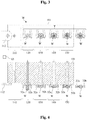
- FIG. 1 a view from the front according to line II in Fig. 2 is shows Fig. 2 a sectional view along the line II-II in Fig. 1 . They are accordingly Figures 3 and 5 Front views and the Figures 4 and 6 associated sectional views.
- the forming device designated as a whole by M in the exemplary embodiment shown comprises five stages 110, 120, 130, 140, 150 arranged next to one another, of which a first stage 110 is a loading stage and the remaining stages 120, 130, 140 and 150 are forming stages.
- the forming stages 120, 130, 140 and 150 comprise four forming dies 121, 131, 141 and 151 formed in a common die holder 101, four forming tools in the form of pressing dies 122, 132, 142 and 152 and four ejection elements 123, 133, 143 and 153, with which workpieces W formed in the forming dies by means of the press rams can be ejected from the forming dies.
- the loading stage 110 comprises a shearing device 112 for shearing off a workpiece W from a rod material (not shown, by means of a rod material feed device, also not shown) and an ejection element 113, with which a workpiece W can be ejected from the shearing device 112.
- a transport device designated overall by T, serves to transfer the workpieces from one stage to the next subsequent stage of the forming device M.
- gripping tools are shown, each with a pair of pliers arms 32a and 32b.
- the pincer-like gripping tools of the transport device T formed by the pincer arm pairs 32a and 32b each take in a starting position one provided in the loading stage 110 or one from the forming dies 121, 131, 141 and 151 of the forming stages 120, 130, 140 and 150 ejected workpiece W on ( Figures 1 and 2 ) and then transport these workpieces W to the next subsequent stage of the forming device M at the same time, the finished formed workpiece W picked up from the last forming step 150 being released so that it can be removed from the forming device.
- the Figures 3 and 4 illustrate this.
- the workpieces W are inserted and shaped into the forming dies 121, 131, 141 and 151 by means of the press punches 122, 132, 142 and 152.
- the transport device T then moves the (empty) gripping tools into the Figures 1 and 2 shown starting position back. There, the gripping tools each take up a new workpiece W provided in the loading stage 110 or ejected from the forming dies 121, 131, 141 and 151 of the forming stages 120, 130, 140 and 150 and in turn transport these workpieces to the next subsequent stage of the forming device, so like this in the Figures 3 and 4 is shown. The whole process takes place in a transport cycle in the machine cycle of the forming device M.
- each gripping tool transports a different workpiece in each relocating cycle and each pair of adjacent stages of the machining device is operated by a different gripping tool.
- the transfer of workpieces from stage to stage of the processing device by means of several gripping tools is to be understood in this sense.
- machining or forming device M shown corresponds in construction and mode of operation to conventional machining or forming devices of this type, so that the person skilled in the art needs no further explanation in this regard.
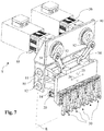
- the transport device designated as a whole by T comprises a stationary frame 10, a plate-like gripping tool carrier 20 which is movably arranged in or on the frame 10 and in this example carries five gripping tool units 30, and a gripping tool carrier drive.
- the gripping tool units 30 are all at the same distance from a common reference plane E ( Fig. 7 ) arranged.
- a front surface of the plate-like gripping tool carrier 20 facing the gripping tool units is aligned parallel to the reference plane E.
- the gripping tool carrier drive comprises two gripping tool carrier drive motors 55 and 56, which are each designed as servomotors with a rotary encoder and gear, and are fixedly mounted on the frame 10. Furthermore, the tool carrier drive comprises two crank gear arrangements, each having a crank 51 or 52 and a drive rod (connecting rod) 53 or 54. The cranks 51 and 52 are each fixedly mounted on a rotatable part of the gears of the gripping tool carrier drive motors 55 and 56 and can be driven in rotation by the latter.
- the frame 10 is detachably or pivotably mounted on the machine body of the shaping device M (not shown), so that access to the shaping dies and to the shaping tools can be released in a simple manner.
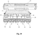
- Two parallel guide rods 11 and 12 are arranged in the frame 10 ( Figures 7-10 ), whose axes define the reference plane E ( Fig. 7 ).
- two links 13 and 14 are linearly movable in the longitudinal direction of the guide rods.
- the two links 13 and 14 are also pivotally pivoted about one of the two guide rods 11 and 12, respectively.
- the links 13 and 14 are connected by means of pairs of pivots 15 and 16 ( Figures 9 and 10th ) swiveling on the gripping tool carrier 20 attached.
- the distance between the two pairs of pivots 15 and 16 is equal to the distance between the two guide rods 11 and 12.
- the distance between the pair of pivots 15 from the guide rod 11 is the same as the distance between the pair of pivots 16 from the guide rod 12.
- the two parallel guide rods 11 and 12 and the two links 13 and 14 thus, together with the gripping tool carrier 20, form a parallelogram guide arrangement for the latter, the gripping tool carrier 20 being deflectable in both directions (up and down in the figures) transversely to the longitudinal direction of the guide rods 11 and 12. In Fig. 7 this is symbolized by the double arrow 25.
- the gripping tool carrier 20 can be moved back and forth along the guide rods 11 and 12 in the longitudinal direction of the guide rods 11 and 12, which is shown in FIG Fig. 7 is indicated by the double arrow 26.
- the gripping tool carrier 20 is thus guided on the one hand in a linearly movable manner parallel to the reference plane E and on the other hand is mounted so as to be deflectable essentially parallel to the reference plane transverse to its linear mobility.
- the drive rods (connecting rods) 53 and 54 are each pivoted at one end on the crank 51 and 52 and at the other end on the gripping tool carrier 20.
- the gripping tool carrier 20 can be moved (within predetermined limits) in the direction of the double arrow 26 and / or the double arrow 25.
- a typical movement path of the gripping tool carrier 20 and thus of the gripping tool units 30 attached to it is shown schematically.
- the self-contained, cyclically traversed movement path 21 comprises four movement path sections 21a-21d.
- the two linear movement path sections 21a and 21c correspond to the linearly guided sliding movement of the gripping tool carrier 20 along the guide rods during the outward movement or Return movement between the stages of the forming device, the two movement path sections 21b and 21d result from the deflection of the gripping tool carrier 20 by means of the parallelogram guide arrangement.
- Points 22 and 23 mark the in Fig. 1 shown starting position or in Fig. 3 illustrated position of the gripping tool carrier 20 shifted by one step Fig.
- FIG. 19 shows, the outward movement of the gripping tool carrier 20 takes place along a first linear movement path (movement path section 21a), while the return movement of the gripping tool carrier 20 takes place along a linear movement path (movement path section 21c) parallel to the first linear movement path.
- the distance between the two linear movement paths resulting from the deflection of the gripping tool carrier 20 is selected such that the gripping tool units 30 arranged on the gripping tool carrier 20 or their gripping tools are at the level of the second linear movement path outside the engagement area of the forming tools 122, 132, 142, 152 are in the forming stages 120, 130, 140, 150, like this Fig. 5 can be seen.
- a waiting position is marked with 27 and will be returned to below.
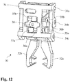
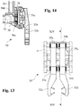
- the gripping tool units 30 arranged next to one another on the gripping tool carrier 20 are all of the same design. Your structure is based on the Figures 11-17 forth.
- Each gripping tool unit 30 comprises a pliers body 31, a pair of movable pliers arms 32a and 32b forming a gripping pliers, and a gripping tool drive in the form of an (electric) servo motor 33 with a rotary encoder and gear, the servo motor only in FIGS Figures 9 and 14 is shown.
- the pliers body 31 and the servo motor 33 including the transmission are each mounted on the gripping tool carrier 20.
- the two gun arms 32a and 32b are movably arranged on the gun body 31.
- Two pliers slides 35a and 35b are slidably mounted in the pliers body 31 on three guide rods 34a, 34b and 34c.
- the pliers slides 35a and 35b are each kinematically connected via a drive rod 36a or 36b to a rack 37a or 37b, so that a movement of the racks causes the pliers slides to move along and vice versa.
- the two racks 37a and 37b are in engagement with a drive pinion 38 on diagonally opposite sides thereof, which can be rotatably driven by the servo motor 33 (via its gearbox), so that when the drive pinion 38 rotates, the two toothed racks 37a and 37b move in opposite directions and thus the two tong arms 32a and 32b are moved towards or away from each other.
- the opening and closing movements of the gripping pliers formed by the pliers arms 32a and 32b thus take place by means of the servo motor 33 or the drive pinion 38 driven thereby.
- the gripping tool drive can alternatively also be designed as a servo-controlled (having servo valves) hydraulic drive. It is essential that the movement of the gripping tongs can be very quick and above all position-controlled on the one hand and the clamping force of the two tongs arms on the other hand can be precisely adjusted or regulated and reported back, as is the case with the gripping tool drive described above with an electric servomotor is.
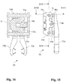
- pliers shoes 39a and 39b are arranged, which serve for gripping the workpieces and are interchangeably fastened, so that the gripping pliers can be easily adapted to the shape of the workpieces to be gripped ( Fig. 11 ).
- the pliers shoes do not have to be designed and / or arranged identically on all gripping pliers.
- two pliers shoes are preferably arranged on each gun arm, which overall form a particularly expedient four-point holder for the workpieces to be gripped.
- Such a four-point holder enables the workpieces to be securely held on the one hand and on the other hand reduces the risk of the workpieces tipping, particularly when inserted into closed gripping tongs.
- the gun arms 32a and 32b are detachably connected to the gun carriages 35a and 35b via a pair of end-toothed plates 40a and 40b, respectively ( Figures 15 and 17th ). In this way, the pliers arms 32a and 32b can easily be adjusted laterally or in height relative to the pliers slides 35a and 35b, for example in order to adapt the gripping pliers to the respective workpiece.
- gripping tongs instead of gripping tongs, differently designed gripping tools can also be used in the transport device according to the invention.
- the gripping tools could also be designed as a vacuum gripper.
- gripping tools in the form of gripping tongs are common and proven.
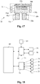
- the transport device T also comprises a carrier control 60 for the gripping tool carrier drive motors 55 and 56 and a gripping tool control 70 for controlling the gripping tool drive motors 33 of the individual gripping tool units 30.
- the gripping tool control 70 is designed to control the opening and closing movements and the clamping force of the individual Gripping tools, here gripping tongs 32a and 32b, to be controlled individually.
- the carrier controller 60 calculates the rotational positions of the two cranks 51 and 52 required in each case for moving the movement path 21 of the gripping tool carrier 20 and controls the servomotors 55 and 56 accordingly.
- the carrier control 60 also cooperates with a sensor device 65, which is designed to detect a process disturbance in the loading stage 110, for example due to a workpiece W ′ which cannot be machined or is missing, and to signal the carrier control 60.
- sensor device 65 is assigned to the already mentioned, not shown bar material feed device and can be, for example, a light barrier arrangement.
- Such sensor devices on bar feeders are known per se and for example in the EP 1 848 556 B1 described.
- the sensor device 65 is able to detect rod beginnings and rod ends. If the sensor device 65 detects a bar start or a bar end, it signals this to the carrier controller 60, so that the carrier controller knows that the next following bar section is faulty and must be eliminated or must not be introduced into the forming process. The carrier controller 60 then reacts to this process fault in the manner explained in more detail below.
- the carrier control 60 and the gripping tool control 70 work together with a higher-level control 80, which, among other things, also establishes the connection to the processing device and specifies at which position of the movement path the gripping tool carrier or its gripping tools should be located.
- a higher-level control 80 By means of the higher-level control 80, an operator can also make settings e.g. Enter or change the movement of the gripping tool holder or the opening and closing movements of the gripping tongs.
- the functions of the carrier control 60, the gripping tool control 70 and the higher-level control 80 can also be implemented in another configuration, e.g. be combined in a single control.
- the raw material is usually supplied in the form of bars, from which pieces of suitable length are then sheared, in forming devices, especially hot forming devices.
- the bar ends and bar starts must not get into the forming process and must be eliminated. These separated sections are missing in the forming process and produce empty forming steps in the forming device, which should be avoided for the reasons explained at the beginning.
- the transport device according to the invention described above creates the possibility of avoiding empty forming steps in a forming device.
- the sensor device 65 sends a corresponding control command to the carrier control 60 for the gripping tool carrier drive.
- the carrier control 60 then causes the gripping tool carrier 20 with the gripping tool units 30 not to follow the usual movement path 21 ( Fig. 19 ) follows, but that the gripping tool carrier 20 with the workpieces W located in the gripping tool units 30 are moved into a waiting position 27 ( Fig. 20 ).
- the waiting position is, for example, on the upper movement path section 21c of the gripping tool carrier 20, the pliers arms 32a and 32b of the gripping tool units 30 being located above and between the tools 112, 122, 132, 142 and 152, so that they are out of reach of the same.
- This situation is in the Figures 5 and 6 shown.
- the forming tools then carry out an idle stroke, but this has no negative consequences, since all the forming stages are empty.
- the tool cooling is preferably interrupted in this phase, so that the tools and the workpieces in the waiting position are not cooled.
- the defective workpiece W ' is eliminated (in a manner known per se).
- the carrier controller 60 causes the gripping tool carrier 20 to return to its original movement path, the workpieces being transferred to the respective forming stages and the gripping tool carrier 20 then along its normal movement path 21 into its in the Figures 1 and 2 shown starting position 22 goes to pick up workpieces W there and then transport them to the next subsequent forming stage.
- Fig. 20 the movement sequence of the gripping tool carrier 20 just described is graphically illustrated in the event of a process fault.
- the movement of the gripping tool carrier 20 into the waiting position 27 takes place along a movement path section 24a and the movement of the gripping tool carrier 20 from the waiting position 27 to the position 23 takes place along a movement path section 24b.
- the entire movement path from position 22 via waiting position 27 to position 23 is designated by 24.
- the movement path sections 24a and 24b do not necessarily have to be the one in FIG Fig. 20 have shown history.
- the gripping tool carrier 20 can also be moved, for example, along alternative movement path sections 24a 'and 24b', which correspond to the movement path sections 21d and 21c or 21c and 21b of the normal movement path 21.
- the duration and distance for transporting, lifting and gripping can be set and varied independently of the stroke of the forming tools.
- Ventilation here means the vertical deflection of the gripping tool carrier 20, the ventilation stroke corresponding to the vertical distance between the two movement path sections 21a and 21c.
- the setting of the lifting and gripping movement which is decoupled from the stroke of the forming tools, allows individual adjustment to the respective workpieces, thereby reducing machine wear.
- the gripping tool units 30 can be individually controlled by means of the gripping tool control 70.
- the time for opening and closing can be set individually for each gripping tool unit.
- the opening stroke of the tong arms 32a and 32b and the duration of the movement can also be matched to the respective workpiece.
- This can also be optimized for each workpiece in terms of stroke and duration with the aim of keeping acceleration and thus load on the construction of the device low.
- known transport devices with control cams must always be designed for the maximum possible stroke, with the result that the components are exposed to maximum stress and therefore maximum wear on each workpiece or formed part.
- the gripping tool carrier 20 can be moved by the desired amount from the center (zero position) by simply entering the desired values on the superordinate control 80 by means of the gripping tool carrier drive motors 55 and 56.
- the gripping tongs in question are then aligned with a central setting element and the gripping tool carrier is then moved back into its zero position. In this way, one or more gripping tongs can be set off-center. The remaining gripping tongs are set when the gripping tool carrier 20 is again centered (in the zero position).
- each gripping tool unit 30 is controlled by means of the gripping tool control 70 via the torque of the associated servo motor 33 and can thus be easily adapted to the workpiece to be held and, if necessary, also varied over the movement cycle of the gripping tool carrier.
- the clamping force can e.g. when inserting the workpieces into the gripper are set smaller than for transport. The load on the mechanical components is only as great as necessary.
- Servomotors usually have a rotary encoder for reporting the current rotary position to their controller.
- the gripping tool control 70 can easily determine whether a gripping tool is filled or empty, for example if a workpiece has been lost from a gripping tool, by comparing the actual to the desired rotational position, so that the forming device can be stopped if necessary.
- process malfunctions which are caused, for example, by crooked workpieces in the gripping tools or tearing of the gripping tools, can also be detected in this way.
- a safe position for example the aforementioned waiting position 27, and stopped there until the process fault has been eliminated.
- the danger of tearing open a gripping tool arises, for example, if a workpiece is incompletely pushed out of the die or the ram breaks and gets stuck in the workpiece. When trying to transport the workpiece, the gripping tool would be torn open. However, the gripping tool control 70 recognizes this at an early stage and, via the carrier control 60, causes the gripping tool carrier to move back so that the gripping tool concerned is not torn open.
- the gripping tool carrier 20 with the gripping tool units 30 is then moved into a safe position, for example the waiting position 27 mentioned, and stopped there until the process fault has been eliminated.
- the forming device is of course stopped during this time. In this way, a process fault can be reacted to immediately before major damage occurs.
- the cooperation of the gripping tool control 70 with the carrier control 60 is shown in FIG Fig. 18 symbolized by arrow 71.
- the gripping tools or gripping tongs of the transport device shown have parallel tongs 32a and 32b which are moved linearly towards or away from each other.
- Such gripping pliers have the advantage over gripping pliers with pivoting pliers arms that the pliers shoes are evenly immersed in the gripping diameter. If the pliers shoes grip the workpiece at the same angle on both sides, they are pressed on by the same amount when the workpiece is inserted. This reduces the risk of a workpiece being slanted into the gripper.
Landscapes
- Engineering & Computer Science (AREA)
- Mechanical Engineering (AREA)
- Manipulator (AREA)
- Multi-Process Working Machines And Systems (AREA)
- Forging (AREA)
- Press Drives And Press Lines (AREA)
- Specific Conveyance Elements (AREA)
- Feeding Of Workpieces (AREA)
Claims (12)
- Procédé de transport pour le transfert de pièces à usiner entre plusieurs étages successifs (110, 120, 130, 140, 150) d'un dispositif d'usinage (M), en particulier d'un dispositif de formage, dans lequel les pièces à usiner (W) sont transportées chacune simultanément au moyen de plusieurs outils de préhension (32a, 32b) mobiles conjointement, dans un cycle de transport depuis un étage à l'étage respectif suivant du dispositif d'usinage (M),
caractérisé en ce que
en présence d'une perturbation du processus, le cycle de transport est interrompu et les outils de préhension (32a, 32b) avec les pièces à usiner (W) sont déplacés jusque dans une position d'attente (27) dans laquelle les pièces à usiner (W) se situent à l'extérieur de la zone d'action d'outils d'usinage (112, 122, 132, 142, 152) des étages (110, 120, 130, 140, 150) du dispositif d'usinage (M), et
après l'élimination de la perturbation du processus, le cycle de transport des pièces à usiner (W) est relancé. - Procédé selon la revendication 1,
dans lequel
la perturbation du processus est causée par une pièce manquante ou non adaptée à l'usinage (W') dans un étage de chargement (110) du dispositif d'usinage. - Procédé selon la revendication 1 ou 2,
dans lequel
la perturbation du processus est causée par une pièce (W) manquante ou insérée incorrectement dans un outil de préhension (32a, 32b). - Procédé selon l'une des revendications 1 à 3,
dans lequel
la perturbation du processus est causée par une partie endommagé d'un outil de préhension (32a, 32b) ou par une partie endommagée du dispositif d'usinage. - Procédé selon la revendication 2,
dans lequel
l'absence d'une pièce (W') ou la présence d'une pièce non adaptée à l'usinage est détectée à l'aide d'un dispositif capteur (65), le mouvement des outils de préhension (32a, 32b) jusque dans la position d'attente (27) étant initié par le dispositif capteur (65). - Procédé selon la revendication 3,
caractérisé en ce que
l'absence d'une pièce (W) ou la présence d'une pièce insérée incorrectement dans un outil de préhension (32a, 32b) est détectée à l'aide d'une commande d'outil de préhension (70) d'un entraînement d'outil de préhension (33), le mouvement des outils de préhension (32a, 32b) jusque dans la position d'attente (27) étant initié par la commande d'outil de préhension (70). - Dispositif de transport pour le transfert simultané de pièces à usiner entre plusieurs étages successifs (110, 120, 130, 140, 150) d'un dispositif d'usinage (M), en particulier d'un dispositif de formage, le dispositif de transport comportant :- un porte-outil de préhension (20) monté de façon mobile, sur lequel sont agencés plusieurs outils de préhension (32a, 32b) pour saisir chacun une pièce à usiner (W),- un entraînement moteur de porte-outil de préhension (51 - 56) pour le mouvement en va-et-vient du porte-outil de préhension (20) avec les outils de préhension (32a, 32b) entre les étages du dispositif d'usinage, et- une commande de porte-outil (60) pour l'entraînement de porte-outil de préhension (51 - 56) qui est conçue pour commander le mouvement du porte-outil de préhension (20) et pour déplacer, sur la base d'un ordre de commande qui lui est envoyé, le porte-outil de préhension (20) avec les outils de préhension (32a, 32b) jusque dans une position d'attente à l'aide de l'entraînement de porte-outil de préhension (51 - 56),caractérisé en ce que
l'entraînement de porte-outil de préhension (51 - 56) et la commande de porte-outil (60) sont conçus pour déplacer le porte-outil de préhension (20) avec les outils de préhension (32a, 32b) avec les pièces à usiner (W) jusque dans la position d'attente (27) et pour interrompre le transport des pièces à usiner (W), en présence d'une perturbation du processus. - Dispositif de transport selon la revendication 7,
caractérisé en ce que
le porte-outil de préhension (20) est d'une part monté de façon mobile en étant guidé linéairement et d'autre part monté de manière à pouvoir être dévié transversalement à sa mobilité guidée linéairement, à l'aide d'un ensemble de guidage à parallélogramme (11 - 16). - Dispositif de transport selon la revendication 8,
caractérisé en ce que
le porte-outil de préhension (20) est mobile à l'aide d'un entraînement de porte-outil de préhension (51 - 56) comportant deux ensembles de transmission à manivelle (51 - 54) ayant chacun un moteur d'entraînement de porte-outil de préhension (55, 56) associé, chaque ensemble de transmission à manivelle (51 - 54) comprenant une manivelle (51, 52) qui peut être entraînée en rotation par le moteur d'entraînement de porte-outil de préhension (55, 56) associé, et une tige d'entraînement (53, 54) qui est reliée en articulation à la manivelle (51, 52), d'une part, et au porte-outil de préhension (20), d'autre part. - Dispositif de transport selon l'une des revendications 7 à 9,
caractérisé en ce que
le porte-outil de préhension (20) comportant les outils de préhension (32a, 32b) peut être déplacé au moyen de l'entraînement de porte-outil de préhension (51 - 56) dans un mouvement d'aller le long d'une première trajectoire de mouvement linéaire (21a) et dans un mouvement de retour le long d'une deuxième trajectoire de mouvement linéaire (21c) parallèle à la première trajectoire de mouvement linéaire. - Dispositif de transport selon l'une des revendications 7 à 10,
caractérisé en ce que
il comprend un dispositif capteur (65) pour détecter une perturbation du processus causée par une pièce à usiner (W') manquante ou non adaptée à l'usinage et pour signaler ladite perturbation à la commande de porte-outil (60). - Dispositif de transport selon l'une des revendications 7 à 11,
caractérisé en ce que
les outils de préhension (32a, 32b) sont chacun dotés d'un entraînement d'outil de préhension (33), disposé sur le porte-outil de préhension (20), pour l'actionnement individuel des outils de préhension (32a, 32b), ainsi que d'une commande d'outil de préhension (70) qui est conçue pour commander individuellement les mouvements d'ouverture et de fermeture et la force de serrage des outils de préhension individuels (32a, 32b), et pour reconnaître une perturbation du processus causée par un outil de préhension vide ou par une pièce insérée incorrectement dans l'outil de préhension, et pour signaler ladite perturbation à la commande de porte-outil (60).
Applications Claiming Priority (2)
| Application Number | Priority Date | Filing Date | Title |
|---|---|---|---|
| CH00562/16A CH712403A1 (de) | 2016-04-28 | 2016-04-28 | Transportverfahren zum Umsetzen von Werkstücken zwischen mehreren aufeinanderfolgenden Stufen einer Bearbeitungseinrichtung. |
| PCT/EP2017/059724 WO2017186675A1 (fr) | 2016-04-28 | 2017-04-25 | Procédé de transport pour la manutention de pièces |
Publications (2)
| Publication Number | Publication Date |
|---|---|
| EP3448597A1 EP3448597A1 (fr) | 2019-03-06 |
| EP3448597B1 true EP3448597B1 (fr) | 2020-06-10 |
Family
ID=56137041
Family Applications (1)
| Application Number | Title | Priority Date | Filing Date |
|---|---|---|---|
| EP17719252.3A Active EP3448597B1 (fr) | 2016-04-28 | 2017-04-25 | Procédé de transport pour la manutention de pièces |
Country Status (10)
| Country | Link |
|---|---|
| US (1) | US10537932B2 (fr) |
| EP (1) | EP3448597B1 (fr) |
| JP (2) | JP7266408B2 (fr) |
| KR (1) | KR102353811B1 (fr) |
| CN (1) | CN109070188B (fr) |
| CH (1) | CH712403A1 (fr) |
| EA (1) | EA201892458A1 (fr) |
| ES (1) | ES2808998T3 (fr) |
| TW (1) | TW201739536A (fr) |
| WO (1) | WO2017186675A1 (fr) |
Families Citing this family (5)
| Publication number | Priority date | Publication date | Assignee | Title |
|---|---|---|---|---|
| ES2870545T3 (es) * | 2018-02-12 | 2021-10-27 | Fagor Arrasate S Coop | Sistema y método para transportar piezas en máquinas de formado |
| EP3627257B1 (fr) * | 2018-09-18 | 2022-11-30 | Siemens Aktiengesellschaft | Planification de mouvement pour un système de transport d'une installation de servopresse |
| JP7083322B2 (ja) * | 2019-07-17 | 2022-06-10 | アイダエンジニアリング株式会社 | トランスファープレスマシンのワーク搬送システム |
| CN111822203B (zh) * | 2020-07-20 | 2022-03-15 | 浙江万丰摩轮有限公司 | 一种摩托车铝合金轮毂智能涂装生产线 |
| CN113443408B (zh) * | 2021-07-20 | 2022-08-12 | 三阳纺织有限公司 | 一种络筒输送装置 |
Family Cites Families (35)
| Publication number | Priority date | Publication date | Assignee | Title |
|---|---|---|---|---|
| US2791786A (en) | 1953-06-29 | 1957-05-14 | Waterbury Farrel Foundry & Mac | Transfer mechanism for progressive headers and the like |
| DE2434540C2 (de) | 1974-07-18 | 1983-09-08 | Hatebur Umformmaschinen AG, Basel | Einrichtung zum automatischen Quertransport von Werkstücken auf mehrstufigen Umformpressen |
| NL8002746A (nl) * | 1980-05-13 | 1981-12-16 | Nedschroef Octrooi Maats | Inrichting voor het overbrengen van te bewerken producten op gereedschapswerktuigen van het ene bewerkingsstation naar het daarop volgende. |
| DE3443874A1 (de) * | 1984-12-01 | 1986-07-10 | L. Schuler GmbH, 7320 Göppingen | Vorrichtung zum foerdern von werkstuecken in einer mehrstufenpresse fuer die massivumformung |
| IT8424221V0 (it) | 1984-12-21 | 1984-12-21 | P Puppieni S P A Sa | Teglia o tegame a fondo antiaderente imbutito con uno o piu' incavi a pozzetto. |
| US4715773A (en) | 1985-06-04 | 1987-12-29 | Clemson University | Method and apparatus for repositioning a mislocated object with a robot hand |
| JPS6478781A (en) | 1987-09-19 | 1989-03-24 | Nissan Motor | Robot hand |
| AT391459B (de) * | 1989-04-04 | 1990-10-10 | Sticht Fertigungstech Stiwa | Einrichtung zum handhaben von bauteilen mit einer greifvorrichtung |
| DE4007801A1 (de) * | 1990-03-12 | 1991-09-19 | Handtmann A Punkt Automation | Einrichtung zum befuellen eines transportbehaelters |
| JP2570460Y2 (ja) * | 1991-12-11 | 1998-05-06 | 旭サナック株式会社 | 圧造機における異常検出装置 |
| US5713236A (en) | 1995-02-08 | 1998-02-03 | The National Machinery Company, | Pick and place transfer |
| DE19508207C2 (de) | 1995-03-08 | 1998-05-14 | Kampf Gmbh & Co Maschf | Rollenschneid- und Wickelmaschine |
| DE19545570A1 (de) | 1995-12-07 | 1997-06-12 | Schuler Pressen Gmbh & Co | Transfereinrichtung für Mehrstationenpressen |
| JP3037672U (ja) * | 1996-11-11 | 1997-05-20 | 株式会社阪村機械製作所 | 多段式圧造成形機の素材移送装置 |
| JP3159659B2 (ja) * | 1996-12-16 | 2001-04-23 | 株式会社栗本鐵工所 | トランスファ装置の制御方法 |
| JP3785547B2 (ja) * | 1997-02-28 | 2006-06-14 | 株式会社大同機械製作所 | 多段式圧造成形機の素材移送装置 |
| JP3821333B2 (ja) * | 1998-02-04 | 2006-09-13 | 株式会社小松製作所 | トランスファフィーダの安全装置 |
| JP2000094070A (ja) * | 1998-09-14 | 2000-04-04 | Kurimoto Ltd | トランスファ装置のミスチャック検出装置 |
| DE10010079A1 (de) | 1999-03-17 | 2000-09-21 | Mueller Weingarten Maschf | Transportsystem |
| JP3486770B2 (ja) * | 1999-09-08 | 2004-01-13 | 住友重機械工業株式会社 | 鍛造プレス装置 |
| US6272892B1 (en) * | 1999-03-19 | 2001-08-14 | Sumitomo Heavy Industries, Ltd. | Forging press apparatus, controller of automation device used therefor and shut height controller |
| DE19919434A1 (de) | 1999-04-29 | 2000-11-02 | Schuler Pressen Gmbh & Co | Einrichtung zum Teiletransfer |
| US6371544B1 (en) | 2000-03-29 | 2002-04-16 | San Shing Hardware Works Co., Ltd. | Workpiece transfer device for a forging machine |
| ITVR20030094A1 (it) * | 2003-08-01 | 2005-02-02 | Amafa Service S R L | Trasferitore di semilavorati su presse multistazioni per il processo |
| TWI294800B (en) | 2005-02-17 | 2008-03-21 | Hatebur Umformmaschinen Ag | Forming machine having a shearing device for shearing a bar |
| ITTO20050511A1 (it) * | 2005-07-25 | 2007-01-26 | Comau Spa | Linea di unita' operatrici per l'esecuzione di lavorazioni di macchina, provvista di dispositivi di trasferimento dei pezzi in lavorazione da un'unita' all'altra della linea |
| ES2309874T3 (es) * | 2006-07-26 | 2008-12-16 | INDAG GESELLSCHAFT FUR INDUSTRIEBEDARF MBH & CO. BETRIEBS KG | Dispositivo prensor. |
| WO2009044556A1 (fr) * | 2007-10-03 | 2009-04-09 | Komatsu Industries Corporation | Appareil de presse de transfert |
| JP5373378B2 (ja) * | 2008-12-03 | 2013-12-18 | 昭和電工株式会社 | 鍛造加工方法 |
| CH700631B1 (it) * | 2009-03-18 | 2014-06-13 | Sacel Srl | Stampo per una pressa per stampaggio progressivo di particolari metallici. |
| WO2011074616A1 (fr) * | 2009-12-15 | 2011-06-23 | 本田技研工業株式会社 | Procédé d'établissement de trajet de transport de ligne de presse, et procédé de création de mouvement de transport de ligne de presse dupliquée |
| CN203437581U (zh) | 2013-08-09 | 2014-02-19 | 浙江正一机械有限公司 | 一种冷镦成型机的可调式180°翻转夹钳机构 |
| CN203418074U (zh) * | 2013-08-25 | 2014-02-05 | 胡金花 | 冷镦机摆臂式机械手机构 |
| CN203917775U (zh) | 2014-04-23 | 2014-11-05 | 浙江鑫联机械制造有限公司 | 一种冷镦机上用平移夹钳机构 |
| CN104308017A (zh) * | 2014-10-11 | 2015-01-28 | 济南奥图自动化工程有限公司 | 一种新型机器人多工位应用系统 |
-
2016
- 2016-04-28 CH CH00562/16A patent/CH712403A1/de unknown
-
2017
- 2017-04-25 CN CN201780025817.6A patent/CN109070188B/zh active Active
- 2017-04-25 US US16/096,752 patent/US10537932B2/en active Active
- 2017-04-25 ES ES17719252T patent/ES2808998T3/es active Active
- 2017-04-25 KR KR1020187030892A patent/KR102353811B1/ko active IP Right Grant
- 2017-04-25 EA EA201892458A patent/EA201892458A1/ru unknown
- 2017-04-25 JP JP2018556301A patent/JP7266408B2/ja active Active
- 2017-04-25 WO PCT/EP2017/059724 patent/WO2017186675A1/fr active Search and Examination
- 2017-04-25 EP EP17719252.3A patent/EP3448597B1/fr active Active
- 2017-04-27 TW TW106114107A patent/TW201739536A/zh unknown
-
2023
- 2023-01-05 JP JP2023000562A patent/JP2023055700A/ja active Pending
Non-Patent Citations (1)
| Title |
|---|
| None * |
Also Published As
| Publication number | Publication date |
|---|---|
| JP7266408B2 (ja) | 2023-04-28 |
| TW201739536A (zh) | 2017-11-16 |
| CN109070188A (zh) | 2018-12-21 |
| CH712403A1 (de) | 2017-10-31 |
| EP3448597A1 (fr) | 2019-03-06 |
| US20190118241A1 (en) | 2019-04-25 |
| KR20190002484A (ko) | 2019-01-08 |
| CN109070188B (zh) | 2020-12-22 |
| JP2019520983A (ja) | 2019-07-25 |
| KR102353811B1 (ko) | 2022-01-20 |
| EA201892458A1 (ru) | 2019-03-29 |
| ES2808998T3 (es) | 2021-03-02 |
| US10537932B2 (en) | 2020-01-21 |
| WO2017186675A1 (fr) | 2017-11-02 |
| JP2023055700A (ja) | 2023-04-18 |
Similar Documents
| Publication | Publication Date | Title |
|---|---|---|
| EP3448597B1 (fr) | Procédé de transport pour la manutention de pièces | |
| DE102005055972B3 (de) | Werkzeugmaschine | |
| EP3448596A1 (fr) | Dispositif de transport à pinces de préhension | |
| EP2233221A2 (fr) | Dispositif de poinçonnage pour une machine de poinçonnage à coupe continue d'éléments de poinçonnage métalliques | |
| DE3925370B4 (de) | Materialvorschubvorrichtung für Schmiedemaschinen u. dgl. | |
| DE1777355B2 (de) | Transporteinrichtung zum Transportieren von Werkstücken zwischen zwei Pressen | |
| WO1997046339A1 (fr) | Machine d'usinage pour pieces sous forme de plaques, notamment pour produire des bords plies sur des pieces en tole | |
| EP3448595B1 (fr) | Dispositif de transport pour déplacer des pièces dans un dispositif d'usinage | |
| EP2505529A1 (fr) | Dispositif de manipulation d'objets | |
| EP0901848B1 (fr) | Presse de transfert avec changement d' outil automatique | |
| DE3116752A1 (de) | Hubbalkenmanipulator fuer gesenkschmiedepressen u.dgl. | |
| EP0778094A1 (fr) | Dispositif de transfert dans presse de formages à postes multiples | |
| DE102004035797B9 (de) | Verfahren und Vorrichtung zum Überführen eines Werkstücks | |
| DE3135266C2 (de) | Schneidpresse zum Herausschneiden oder -trennen von Teilen aus einer Werkstücktafel | |
| EP3344417B1 (fr) | Module de fabrication et procédé pour faire fonctionner ce module de fabrication | |
| EP4007664B1 (fr) | Procédé de transfert, système de manipulation conçu pour celui-ci, et unité de pliage | |
| DE3722545C2 (fr) | ||
| EP2210701B1 (fr) | Système de fabrication linéaire | |
| DE3338096A1 (de) | Verfahren und vorrichtung zum ablaengen von metallenen langformguetern | |
| DE2258647A1 (de) | Presse mit zwei um die eine bzw. andere von zwei parallelen drehachsen synchron rotierenden werkzeugtraegern | |
| DE1802629C3 (de) | Vorrichtung zum Überführen von Werkstücken zwischen aufeinanderfolgenden Bearbeitungsstationen an Pressen und dergleichen Werkzeugmaschinen | |
| EP3627258B1 (fr) | Planification de mouvement pour une presse servo | |
| DE19755338C2 (de) | Zuführvorrichtung und Zuführverfahren für plattenförmige Werkstücke | |
| EP3181254B1 (fr) | Installation de fabrication comprenant une unité de manipulation d'outil | |
| AT343434B (de) | Vorrichtung zur entnahme, zum vereinzeln und zur weitergabe von platten- oder scheibenformigen werkstucken |
Legal Events
| Date | Code | Title | Description |
|---|---|---|---|
| STAA | Information on the status of an ep patent application or granted ep patent |
Free format text: STATUS: UNKNOWN |
|
| STAA | Information on the status of an ep patent application or granted ep patent |
Free format text: STATUS: THE INTERNATIONAL PUBLICATION HAS BEEN MADE |
|
| PUAI | Public reference made under article 153(3) epc to a published international application that has entered the european phase |
Free format text: ORIGINAL CODE: 0009012 |
|
| STAA | Information on the status of an ep patent application or granted ep patent |
Free format text: STATUS: REQUEST FOR EXAMINATION WAS MADE |
|
| 17P | Request for examination filed |
Effective date: 20181123 |
|
| AK | Designated contracting states |
Kind code of ref document: A1 Designated state(s): AL AT BE BG CH CY CZ DE DK EE ES FI FR GB GR HR HU IE IS IT LI LT LU LV MC MK MT NL NO PL PT RO RS SE SI SK SM TR |
|
| AX | Request for extension of the european patent |
Extension state: BA ME |
|
| RIN1 | Information on inventor provided before grant (corrected) |
Inventor name: LEIBUNDGUT, STEPHAN Inventor name: MARITZ, ANDREAS Inventor name: MATT, ANDREAS Inventor name: MOSER, MARKUS |
|
| DAV | Request for validation of the european patent (deleted) | ||
| DAX | Request for extension of the european patent (deleted) | ||
| GRAP | Despatch of communication of intention to grant a patent |
Free format text: ORIGINAL CODE: EPIDOSNIGR1 |
|
| STAA | Information on the status of an ep patent application or granted ep patent |
Free format text: STATUS: GRANT OF PATENT IS INTENDED |
|
| INTG | Intention to grant announced |
Effective date: 20191203 |
|
| GRAS | Grant fee paid |
Free format text: ORIGINAL CODE: EPIDOSNIGR3 |
|
| GRAA | (expected) grant |
Free format text: ORIGINAL CODE: 0009210 |
|
| STAA | Information on the status of an ep patent application or granted ep patent |
Free format text: STATUS: THE PATENT HAS BEEN GRANTED |
|
| AK | Designated contracting states |
Kind code of ref document: B1 Designated state(s): AL AT BE BG CH CY CZ DE DK EE ES FI FR GB GR HR HU IE IS IT LI LT LU LV MC MK MT NL NO PL PT RO RS SE SI SK SM TR |
|
| REG | Reference to a national code |
Ref country code: GB Ref legal event code: FG4D Free format text: NOT ENGLISH |
|
| REG | Reference to a national code |
Ref country code: CH Ref legal event code: EP Ref country code: AT Ref legal event code: REF Ref document number: 1278795 Country of ref document: AT Kind code of ref document: T Effective date: 20200615 |
|
| REG | Reference to a national code |
Ref country code: DE Ref legal event code: R096 Ref document number: 502017005656 Country of ref document: DE |
|
| REG | Reference to a national code |
Ref country code: IE Ref legal event code: FG4D Free format text: LANGUAGE OF EP DOCUMENT: GERMAN |
|
| REG | Reference to a national code |
Ref country code: CH Ref legal event code: NV Representative=s name: BOHEST AG, CH |
|
| REG | Reference to a national code |
Ref country code: NL Ref legal event code: FP |
|
| REG | Reference to a national code |
Ref country code: LT Ref legal event code: MG4D |
|
| PG25 | Lapsed in a contracting state [announced via postgrant information from national office to epo] |
Ref country code: SE Free format text: LAPSE BECAUSE OF FAILURE TO SUBMIT A TRANSLATION OF THE DESCRIPTION OR TO PAY THE FEE WITHIN THE PRESCRIBED TIME-LIMIT Effective date: 20200610 Ref country code: FI Free format text: LAPSE BECAUSE OF FAILURE TO SUBMIT A TRANSLATION OF THE DESCRIPTION OR TO PAY THE FEE WITHIN THE PRESCRIBED TIME-LIMIT Effective date: 20200610 Ref country code: NO Free format text: LAPSE BECAUSE OF FAILURE TO SUBMIT A TRANSLATION OF THE DESCRIPTION OR TO PAY THE FEE WITHIN THE PRESCRIBED TIME-LIMIT Effective date: 20200910 Ref country code: LT Free format text: LAPSE BECAUSE OF FAILURE TO SUBMIT A TRANSLATION OF THE DESCRIPTION OR TO PAY THE FEE WITHIN THE PRESCRIBED TIME-LIMIT Effective date: 20200610 Ref country code: GR Free format text: LAPSE BECAUSE OF FAILURE TO SUBMIT A TRANSLATION OF THE DESCRIPTION OR TO PAY THE FEE WITHIN THE PRESCRIBED TIME-LIMIT Effective date: 20200911 |
|
| PG25 | Lapsed in a contracting state [announced via postgrant information from national office to epo] |
Ref country code: LV Free format text: LAPSE BECAUSE OF FAILURE TO SUBMIT A TRANSLATION OF THE DESCRIPTION OR TO PAY THE FEE WITHIN THE PRESCRIBED TIME-LIMIT Effective date: 20200610 Ref country code: RS Free format text: LAPSE BECAUSE OF FAILURE TO SUBMIT A TRANSLATION OF THE DESCRIPTION OR TO PAY THE FEE WITHIN THE PRESCRIBED TIME-LIMIT Effective date: 20200610 Ref country code: BG Free format text: LAPSE BECAUSE OF FAILURE TO SUBMIT A TRANSLATION OF THE DESCRIPTION OR TO PAY THE FEE WITHIN THE PRESCRIBED TIME-LIMIT Effective date: 20200910 Ref country code: HR Free format text: LAPSE BECAUSE OF FAILURE TO SUBMIT A TRANSLATION OF THE DESCRIPTION OR TO PAY THE FEE WITHIN THE PRESCRIBED TIME-LIMIT Effective date: 20200610 |
|
| PG25 | Lapsed in a contracting state [announced via postgrant information from national office to epo] |
Ref country code: AL Free format text: LAPSE BECAUSE OF FAILURE TO SUBMIT A TRANSLATION OF THE DESCRIPTION OR TO PAY THE FEE WITHIN THE PRESCRIBED TIME-LIMIT Effective date: 20200610 |
|
| PG25 | Lapsed in a contracting state [announced via postgrant information from national office to epo] |
Ref country code: RO Free format text: LAPSE BECAUSE OF FAILURE TO SUBMIT A TRANSLATION OF THE DESCRIPTION OR TO PAY THE FEE WITHIN THE PRESCRIBED TIME-LIMIT Effective date: 20200610 Ref country code: EE Free format text: LAPSE BECAUSE OF FAILURE TO SUBMIT A TRANSLATION OF THE DESCRIPTION OR TO PAY THE FEE WITHIN THE PRESCRIBED TIME-LIMIT Effective date: 20200610 Ref country code: SM Free format text: LAPSE BECAUSE OF FAILURE TO SUBMIT A TRANSLATION OF THE DESCRIPTION OR TO PAY THE FEE WITHIN THE PRESCRIBED TIME-LIMIT Effective date: 20200610 Ref country code: PT Free format text: LAPSE BECAUSE OF FAILURE TO SUBMIT A TRANSLATION OF THE DESCRIPTION OR TO PAY THE FEE WITHIN THE PRESCRIBED TIME-LIMIT Effective date: 20201012 |
|
| PG25 | Lapsed in a contracting state [announced via postgrant information from national office to epo] |
Ref country code: SK Free format text: LAPSE BECAUSE OF FAILURE TO SUBMIT A TRANSLATION OF THE DESCRIPTION OR TO PAY THE FEE WITHIN THE PRESCRIBED TIME-LIMIT Effective date: 20200610 Ref country code: PL Free format text: LAPSE BECAUSE OF FAILURE TO SUBMIT A TRANSLATION OF THE DESCRIPTION OR TO PAY THE FEE WITHIN THE PRESCRIBED TIME-LIMIT Effective date: 20200610 Ref country code: IS Free format text: LAPSE BECAUSE OF FAILURE TO SUBMIT A TRANSLATION OF THE DESCRIPTION OR TO PAY THE FEE WITHIN THE PRESCRIBED TIME-LIMIT Effective date: 20201010 |
|
| REG | Reference to a national code |
Ref country code: ES Ref legal event code: FG2A Ref document number: 2808998 Country of ref document: ES Kind code of ref document: T3 Effective date: 20210302 |
|
| REG | Reference to a national code |
Ref country code: DE Ref legal event code: R097 Ref document number: 502017005656 Country of ref document: DE |
|
| PLBE | No opposition filed within time limit |
Free format text: ORIGINAL CODE: 0009261 |
|
| STAA | Information on the status of an ep patent application or granted ep patent |
Free format text: STATUS: NO OPPOSITION FILED WITHIN TIME LIMIT |
|
| PG25 | Lapsed in a contracting state [announced via postgrant information from national office to epo] |
Ref country code: DK Free format text: LAPSE BECAUSE OF FAILURE TO SUBMIT A TRANSLATION OF THE DESCRIPTION OR TO PAY THE FEE WITHIN THE PRESCRIBED TIME-LIMIT Effective date: 20200610 |
|
| 26N | No opposition filed |
Effective date: 20210311 |
|
| PG25 | Lapsed in a contracting state [announced via postgrant information from national office to epo] |
Ref country code: SI Free format text: LAPSE BECAUSE OF FAILURE TO SUBMIT A TRANSLATION OF THE DESCRIPTION OR TO PAY THE FEE WITHIN THE PRESCRIBED TIME-LIMIT Effective date: 20200610 |
|
| PG25 | Lapsed in a contracting state [announced via postgrant information from national office to epo] |
Ref country code: MC Free format text: LAPSE BECAUSE OF FAILURE TO SUBMIT A TRANSLATION OF THE DESCRIPTION OR TO PAY THE FEE WITHIN THE PRESCRIBED TIME-LIMIT Effective date: 20200610 |
|
| PG25 | Lapsed in a contracting state [announced via postgrant information from national office to epo] |
Ref country code: LU Free format text: LAPSE BECAUSE OF NON-PAYMENT OF DUE FEES Effective date: 20210425 |
|
| PG25 | Lapsed in a contracting state [announced via postgrant information from national office to epo] |
Ref country code: IE Free format text: LAPSE BECAUSE OF NON-PAYMENT OF DUE FEES Effective date: 20210425 |
|
| PG25 | Lapsed in a contracting state [announced via postgrant information from national office to epo] |
Ref country code: IS Free format text: LAPSE BECAUSE OF FAILURE TO SUBMIT A TRANSLATION OF THE DESCRIPTION OR TO PAY THE FEE WITHIN THE PRESCRIBED TIME-LIMIT Effective date: 20201010 |
|
| P01 | Opt-out of the competence of the unified patent court (upc) registered |
Effective date: 20230504 |
|
| REG | Reference to a national code |
Ref country code: AT Ref legal event code: MM01 Ref document number: 1278795 Country of ref document: AT Kind code of ref document: T Effective date: 20220425 |
|
| PG25 | Lapsed in a contracting state [announced via postgrant information from national office to epo] |
Ref country code: CY Free format text: LAPSE BECAUSE OF FAILURE TO SUBMIT A TRANSLATION OF THE DESCRIPTION OR TO PAY THE FEE WITHIN THE PRESCRIBED TIME-LIMIT Effective date: 20200610 |
|
| PG25 | Lapsed in a contracting state [announced via postgrant information from national office to epo] |
Ref country code: HU Free format text: LAPSE BECAUSE OF FAILURE TO SUBMIT A TRANSLATION OF THE DESCRIPTION OR TO PAY THE FEE WITHIN THE PRESCRIBED TIME-LIMIT; INVALID AB INITIO Effective date: 20170425 Ref country code: AT Free format text: LAPSE BECAUSE OF NON-PAYMENT OF DUE FEES Effective date: 20220425 |
|
| PG25 | Lapsed in a contracting state [announced via postgrant information from national office to epo] |
Ref country code: MK Free format text: LAPSE BECAUSE OF FAILURE TO SUBMIT A TRANSLATION OF THE DESCRIPTION OR TO PAY THE FEE WITHIN THE PRESCRIBED TIME-LIMIT Effective date: 20200610 |
|
| PGFP | Annual fee paid to national office [announced via postgrant information from national office to epo] |
Ref country code: CZ Payment date: 20240314 Year of fee payment: 8 |
|
| PGFP | Annual fee paid to national office [announced via postgrant information from national office to epo] |
Ref country code: NL Payment date: 20240408 Year of fee payment: 8 |
|
| PG25 | Lapsed in a contracting state [announced via postgrant information from national office to epo] |
Ref country code: TR Free format text: LAPSE BECAUSE OF FAILURE TO SUBMIT A TRANSLATION OF THE DESCRIPTION OR TO PAY THE FEE WITHIN THE PRESCRIBED TIME-LIMIT Effective date: 20200610 |
|
| PGFP | Annual fee paid to national office [announced via postgrant information from national office to epo] |
Ref country code: GB Payment date: 20240405 Year of fee payment: 8 |
|
| PGFP | Annual fee paid to national office [announced via postgrant information from national office to epo] |
Ref country code: DE Payment date: 20240326 Year of fee payment: 8 |
|
| PGFP | Annual fee paid to national office [announced via postgrant information from national office to epo] |
Ref country code: CH Payment date: 20240501 Year of fee payment: 8 |
|
| PGFP | Annual fee paid to national office [announced via postgrant information from national office to epo] |
Ref country code: ES Payment date: 20240503 Year of fee payment: 8 |
|
| PGFP | Annual fee paid to national office [announced via postgrant information from national office to epo] |
Ref country code: IT Payment date: 20240405 Year of fee payment: 8 Ref country code: FR Payment date: 20240403 Year of fee payment: 8 |
|
| PGFP | Annual fee paid to national office [announced via postgrant information from national office to epo] |
Ref country code: BE Payment date: 20240415 Year of fee payment: 8 |