EP2233221A2 - Dispositif de poinçonnage pour une machine de poinçonnage à coupe continue d'éléments de poinçonnage métalliques - Google Patents
Dispositif de poinçonnage pour une machine de poinçonnage à coupe continue d'éléments de poinçonnage métalliques Download PDFInfo
- Publication number
- EP2233221A2 EP2233221A2 EP10405048A EP10405048A EP2233221A2 EP 2233221 A2 EP2233221 A2 EP 2233221A2 EP 10405048 A EP10405048 A EP 10405048A EP 10405048 A EP10405048 A EP 10405048A EP 2233221 A2 EP2233221 A2 EP 2233221A2
- Authority
- EP
- European Patent Office
- Prior art keywords
- punching
- station
- punching device
- follow
- punch press
- Prior art date
- Legal status (The legal status is an assumption and is not a legal conclusion. Google has not performed a legal analysis and makes no representation as to the accuracy of the status listed.)
- Withdrawn
Links
Images
Classifications
-
- B—PERFORMING OPERATIONS; TRANSPORTING
- B21—MECHANICAL METAL-WORKING WITHOUT ESSENTIALLY REMOVING MATERIAL; PUNCHING METAL
- B21D—WORKING OR PROCESSING OF SHEET METAL OR METAL TUBES, RODS OR PROFILES WITHOUT ESSENTIALLY REMOVING MATERIAL; PUNCHING METAL
- B21D28/00—Shaping by press-cutting; Perforating
- B21D28/24—Perforating, i.e. punching holes
- B21D28/36—Perforating, i.e. punching holes using rotatable work or tool holders
-
- B—PERFORMING OPERATIONS; TRANSPORTING
- B21—MECHANICAL METAL-WORKING WITHOUT ESSENTIALLY REMOVING MATERIAL; PUNCHING METAL
- B21D—WORKING OR PROCESSING OF SHEET METAL OR METAL TUBES, RODS OR PROFILES WITHOUT ESSENTIALLY REMOVING MATERIAL; PUNCHING METAL
- B21D24/00—Special deep-drawing arrangements in, or in connection with, presses
- B21D24/005—Multi-stage presses
-
- B—PERFORMING OPERATIONS; TRANSPORTING
- B21—MECHANICAL METAL-WORKING WITHOUT ESSENTIALLY REMOVING MATERIAL; PUNCHING METAL
- B21D—WORKING OR PROCESSING OF SHEET METAL OR METAL TUBES, RODS OR PROFILES WITHOUT ESSENTIALLY REMOVING MATERIAL; PUNCHING METAL
- B21D28/00—Shaping by press-cutting; Perforating
- B21D28/24—Perforating, i.e. punching holes
- B21D28/26—Perforating, i.e. punching holes in sheets or flat parts
-
- B—PERFORMING OPERATIONS; TRANSPORTING
- B21—MECHANICAL METAL-WORKING WITHOUT ESSENTIALLY REMOVING MATERIAL; PUNCHING METAL
- B21D—WORKING OR PROCESSING OF SHEET METAL OR METAL TUBES, RODS OR PROFILES WITHOUT ESSENTIALLY REMOVING MATERIAL; PUNCHING METAL
- B21D37/00—Tools as parts of machines covered by this subclass
- B21D37/08—Dies with different parts for several steps in a process
-
- B—PERFORMING OPERATIONS; TRANSPORTING
- B21—MECHANICAL METAL-WORKING WITHOUT ESSENTIALLY REMOVING MATERIAL; PUNCHING METAL
- B21D—WORKING OR PROCESSING OF SHEET METAL OR METAL TUBES, RODS OR PROFILES WITHOUT ESSENTIALLY REMOVING MATERIAL; PUNCHING METAL
- B21D43/00—Feeding, positioning or storing devices combined with, or arranged in, or specially adapted for use in connection with, apparatus for working or processing sheet metal, metal tubes or metal profiles; Associations therewith of cutting devices
- B21D43/02—Advancing work in relation to the stroke of the die or tool
- B21D43/04—Advancing work in relation to the stroke of the die or tool by means in mechanical engagement with the work
- B21D43/05—Advancing work in relation to the stroke of the die or tool by means in mechanical engagement with the work specially adapted for multi-stage presses
-
- B—PERFORMING OPERATIONS; TRANSPORTING
- B21—MECHANICAL METAL-WORKING WITHOUT ESSENTIALLY REMOVING MATERIAL; PUNCHING METAL
- B21D—WORKING OR PROCESSING OF SHEET METAL OR METAL TUBES, RODS OR PROFILES WITHOUT ESSENTIALLY REMOVING MATERIAL; PUNCHING METAL
- B21D43/00—Feeding, positioning or storing devices combined with, or arranged in, or specially adapted for use in connection with, apparatus for working or processing sheet metal, metal tubes or metal profiles; Associations therewith of cutting devices
- B21D43/02—Advancing work in relation to the stroke of the die or tool
- B21D43/04—Advancing work in relation to the stroke of the die or tool by means in mechanical engagement with the work
- B21D43/14—Advancing work in relation to the stroke of the die or tool by means in mechanical engagement with the work by turning devices, e.g. turn-tables
Definitions
- the present invention relates to a punching device for a follow-cut punching machine for the production of metal stamped parts according to the preamble of patent claim 1.
- the metal part is processed in a series of workstations which are each provided with at least one punch and one die, each of which is provided for carrying out a specific work step, for example for severing and / or folding and / or drawing or thermoforming.
- a specific work step for example for severing and / or folding and / or drawing or thermoforming.
- the metal part changes shape until the final shape is achieved according to the design drawing.
- stamp here always a combination of one or more stamps in conjunction with its own associated die to understand.
- a "simple" punch press that can perform a single punching operation has a punch and a single die, while a progressive punch press has a series of punches, each with its own die.
- the feed of the sheet metal strip, and thus also of the stamped part is given by the feed device of the punch press, which advances the strip by one "step" for each punching stroke (the step being in the case of a number of more than two workstations of the follow-cut punch press is equal to the distance between one workstation and the next one).
- the above-described technology of the following step punching can not be used, in which the stamped part remains connected to the sheet metal strip and thus transported with it until it is cut off (cut off) only at the last work station. It may happen, for example, that certain stampings have no area in which the connection with the sheet-metal strip can remain. In such cases, the stamped part must already be separated from the band at the first workstation and then brought as a separate or independent part to the subsequent workstations.
- transfer punching technology in which the punching device is replaced by a series of individual stations arranged in a straight line, the transfer from one station to the next by means of a series of grippers accomplished, which are attached to a transporting arm.
- transfer punch press Such a transport system becomes an integral part of the stamping press, thus called “transfer punch press”, which is a special punch press type.
- this particular type of punch press is known as a "transfer punch press", with punching stations arranged in a single plane for punched parts cut off from the sheet metal strip from the first work station.
- This is, in the sense of an example, from the EP0778094 can be seen in the gripper devices formed by gripper tongs, with an access station and with an unloading station, wherein each of the clamping devices is mounted on a suitable sliding rod, or from the DE4022560 in which the punching stations are arranged along a zig-zag course to reduce the space requirement, the gripper arms transporting the stamped parts along this path.
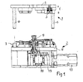
- the Fig. 1 shows the punching press according to the invention in elevation. It consists of an upper part 1 and a lower part. 2
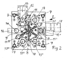
- Fig. 1 In the Fig. 1 are the two parts 1 and 2, which together form the punching device, are shown lifted off from each other: this is the position of the punching device in its open position or rest position. It is clear that in the working position, the punching stroke, the upper part 1 lowers to the lower part 2, so that the stamp (in the Fig. 2 only one punch 3 is shown in section) can penetrate into the corresponding dies 4, which in the Fig. 2 can be seen better, showing the bottom of the punching press in plan.
- the punching device 1,2 is shown on a punch press, which is not shown here for the sake of clarity, and because it is a conventional punch press type comprising a base 2 supporting frame, a horizontal portal on which the upper part. 1 the punching device is attached, as well as vertical guides along which the portal can move upwards (for opening the punching device) and downwards (for closing the punching device during the punching stroke), and the required movement and control mechanisms for the portal. All these movements are in the Fig. 1 indicated by the double arrow f itself, which indicates the movements of the upper part of the punching device upwards and downwards.
- the upper part 1 of the punching device consists of a substantially horizontal plate 5, on which the punch 3 in a well-defined arrangement resulting from the positions of the dies 4, which are fixed in the lower part 2 of the punching device, and, as explained later is a basic aspect of the present invention, as well as four guide elements 6 (one for each corner of the plate 5) whose purpose it is to guide the plate exactly when lowering on the lower part 2 of the punching device.
- Fig. 2 showing the bottom part 2 of the punching device with the top removed in plan view.
- Fig. 2 corresponds to the horizontal plate 8 of the lower part 2 of the punching device in shape of the plate 5 in the upper part 1, wherein through the center of the axis of rotation 9 of an arm star 10 extends, which is provided with gripper claws 11.
- the processing stations 12, 13, 13 ', 13 ", 13"' have matrices 4, each of which is designed for the operation to be performed in cooperation with the corresponding punch 3.
- Each processing station is thus equipped with a punch and a die which are different from those of the preceding station, so that the continuous deformation of the stamped part is performed.
- the processing stations 12, 13, 13 ', 13 ", 13"' and 14 are arranged according to the invention along a circular path which begins with a loading and cutting station 12 and ends with an unloading station 14.
- the charging station 12 while the stamped part is separated or cut from the metal strip 15 and thus becomes an independent part, which at best also experiences a first deformation by pulling during the separation, and thus, after it has been gripped by the gripper jaw 11 of the corresponding arm of the arm star 10, can be transported to the next processing station 13 , To perform this operation, the arm star 10, starting from his in the Fig.
- the arm star 10 shown at first a rotational movement about the center of the circular path from, in the counterclockwise direction, over an angle corresponding to half the angular distance between two successive arms of the arm star 10, so that the gripper claw 11 over the separated in the processing station 12 part located. Then, the claw 11 suitably grips the part and the arm of the star-shaped arm 10 rotates clockwise through an angle corresponding to the angular distance between two consecutive arms of the arm star 10, so that the part is in coaxial coincidence with the processing station 13 is brought. Then, the arm star 10 returns to its original position by making a counterclockwise rotation through an angle equal to half the angular distance between two successive arms of the arm star 10.
- the number of arms of Arm Star 10 depends on the number of processing stations provided along the circular path, and is always equal to this number minus one.
- FIGS. 1 and 2 In the illustrated case of an implementation of the present invention, which may be considered as a preferred case for many practical applications, six processing stations 12, 13, 13 ', 13 ", 13"' and 14 are provided which are angularly spaced from one another by 60 ° station arranged to the other.
- the arm star 10 has five arms, between two of which - those cooperating with the loading and unloading station 12 and the unloading station 14 - the angular distance is 120 °.
- FIGS. 1 and 2 is, merely in the sense of an example, a drive motor 17 for the arm star 10 shown, which acts via a reduction gear 18 and a camshaft 19.
- this arrangement is not part of the inventive idea and is left to the creativity of the designer.
- the present invention has been described here on the basis of a vertical punch press, in which the upper part 1 of the punching device is lowered onto the lower part 2 in a vertical movement.
- This is a preferred way of realizing the inventive concept, as it allows the use of normal punching presses with vertical lifting movement.
- the present invention can also be applied independently of the particular arrangement of the plane in which the circular path of the processing stations is designed, for example on stamping presses in which the lifting movement of the punching in the horizontal or similar (inclined) direction he follows.
- the access type of gripper jaws 11, 11 ', 11 ", 11"', 11 IV of the arm star 10 on the stamped part depending on the shape of the can be different to be produced stamped part.
- the gripper jaws 11,... 11 IV are equipped with pliers which mechanically grasp the stamped part, wherein according to a further preferred embodiment of the present invention, the pliers are pneumatic or hydraulically operated.
- a further preferred embodiment of the present invention then provides that the gripper jaws 11, 11 ', 11 ", 11"', 11 IV are equipped for the metallic stampings with suction cups, which access by means of pneumatic suction, or by means of magnetic attraction.
Landscapes
- Engineering & Computer Science (AREA)
- Mechanical Engineering (AREA)
- Press Drives And Press Lines (AREA)
Applications Claiming Priority (1)
| Application Number | Priority Date | Filing Date | Title |
|---|---|---|---|
| CH00404/09A CH700631B1 (it) | 2009-03-18 | 2009-03-18 | Stampo per una pressa per stampaggio progressivo di particolari metallici. |
Publications (2)
| Publication Number | Publication Date |
|---|---|
| EP2233221A2 true EP2233221A2 (fr) | 2010-09-29 |
| EP2233221A3 EP2233221A3 (fr) | 2011-04-06 |
Family
ID=42313854
Family Applications (1)
| Application Number | Title | Priority Date | Filing Date |
|---|---|---|---|
| EP10405048A Withdrawn EP2233221A3 (fr) | 2009-03-18 | 2010-03-10 | Dispositif de poinçonnage pour une machine de poinçonnage à coupe continue d'éléments de poinçonnage métalliques |
Country Status (2)
| Country | Link |
|---|---|
| EP (1) | EP2233221A3 (fr) |
| CH (1) | CH700631B1 (fr) |
Cited By (20)
| Publication number | Priority date | Publication date | Assignee | Title |
|---|---|---|---|---|
| EP2524742A3 (fr) * | 2011-05-19 | 2013-09-04 | MBB Fertigungstechnik GmbH | Presse cadencée |
| CN104070098A (zh) * | 2014-06-12 | 2014-10-01 | 宁波新冠联机电有限公司 | 一种多工位冲压装置 |
| EP2842654A1 (fr) * | 2013-08-26 | 2015-03-04 | Feintool International Holding AG | Dispositif et procédé de transfert de pièces à usiner dans et hors d'un outil |
| CN104607535A (zh) * | 2015-01-20 | 2015-05-13 | 无锡铸华机械科技有限公司 | 一种汽车玻璃导轨自动化冲切专机 |
| CN105033011A (zh) * | 2015-08-05 | 2015-11-11 | 余姚市新新塑胶制品有限公司 | 用于给阀座冲r的设备 |
| CN106984727A (zh) * | 2017-05-20 | 2017-07-28 | 中山鑫辉精密技术股份有限公司 | 一种立式多工位加工平台以及使用该平台的加工设备 |
| CN107262608A (zh) * | 2017-08-15 | 2017-10-20 | 聊城市博源节能科技有限公司 | 汽车冲压件的冲压装置 |
| CH712403A1 (de) * | 2016-04-28 | 2017-10-31 | Hatebur Umformmaschinen Ag | Transportverfahren zum Umsetzen von Werkstücken zwischen mehreren aufeinanderfolgenden Stufen einer Bearbeitungseinrichtung. |
| FR3070883A1 (fr) * | 2017-09-13 | 2019-03-15 | Psa Automobiles Sa | Installation d’emboutissage pour transformation de pieces sur des postes successifs |
| CN110328531A (zh) * | 2019-07-18 | 2019-10-15 | 宁波市姚江机床制造有限公司 | 一种智能埋线机 |
| CN110918855A (zh) * | 2019-11-28 | 2020-03-27 | 佛山市兴源标准件有限公司 | 一种螺钉打头机系统 |
| CN110918720A (zh) * | 2019-12-04 | 2020-03-27 | 淮北万里龙波电气有限公司 | 一种开关柜内部金属安装条冲压成型设备 |
| US10737313B2 (en) | 2016-04-28 | 2020-08-11 | Hatebur Umformmaschinen Ag | Transport apparatus for transferring workpieces in a processing device |
| CN114101457A (zh) * | 2021-11-28 | 2022-03-01 | 海安金锻工业有限公司 | 一种冲压成型生产线 |
| CN114210801A (zh) * | 2021-12-17 | 2022-03-22 | 广东盈峰材料技术股份有限公司 | 一种半自动冲压设备 |
| CN114378626A (zh) * | 2022-03-04 | 2022-04-22 | 连云港久鑫电子有限公司 | 一种智能电子配件加工用自动上下料装置 |
| CN114472711A (zh) * | 2021-12-29 | 2022-05-13 | 浙江博秦精密工业有限公司 | 一种笔记本电脑壳体冲压用连续模具及冲压方法 |
| CN115338602A (zh) * | 2022-08-25 | 2022-11-15 | 汇昊工业制造(大连)有限公司 | 太阳能光板安装座加工方法 |
| CN115415428A (zh) * | 2022-08-17 | 2022-12-02 | 互赢科技(东莞)有限公司 | 圆柱动力电池钢壳封口机 |
| CN118268445A (zh) * | 2024-06-03 | 2024-07-02 | 杭州米格电机有限公司 | 一种电机转子冲片冲压成型装置 |
Families Citing this family (3)
| Publication number | Priority date | Publication date | Assignee | Title |
|---|---|---|---|---|
| CN112893631A (zh) * | 2021-03-16 | 2021-06-04 | 北京亿华通科技股份有限公司 | 级进冲压模具和用于加工燃料电池双极板的冲压加工方法 |
| CN114029391A (zh) * | 2021-08-11 | 2022-02-11 | 滁州市朝友精密制造有限公司 | 一种电气柜钣金冲压加工设备 |
| CN116652019B (zh) * | 2023-07-28 | 2023-11-03 | 汉狮光动科技(广东)有限公司 | 一种用于百叶窗户加工用的百叶叶片穿孔设备及其方法 |
Citations (2)
| Publication number | Priority date | Publication date | Assignee | Title |
|---|---|---|---|---|
| DE4022560A1 (de) | 1990-07-16 | 1992-01-23 | Manfred Wanzke | Multistationsbearbeitungsgeraet mit transfereinrichtung |
| EP0778094A1 (fr) | 1995-12-07 | 1997-06-11 | SCHULER PRESSEN GmbH & Co. | Dispositif de transfert dans presse de formages à postes multiples |
Family Cites Families (6)
| Publication number | Priority date | Publication date | Assignee | Title |
|---|---|---|---|---|
| GB688046A (en) * | 1949-04-26 | 1953-02-25 | Ideal Capsules Ltd | A machine for making pleated metal foil capsules |
| GB774562A (en) * | 1954-09-11 | 1957-05-08 | Meccaniche Benelli Gavazzi Soc | Improvements in machines for the die-forming of metallic sheet elements |
| GB955339A (en) * | 1960-08-22 | 1964-04-15 | Joseph Rhodes & Sons Ltd | Improvements in or relating to multi-stage press feeding and feed means |
| US4287748A (en) * | 1979-09-28 | 1981-09-08 | Stewart Stamping Corp. | Rotary transfer press apparatus |
| EP0220214A1 (fr) * | 1985-04-26 | 1987-05-06 | STYNER & BIENZ AG | Installation de transfert |
| ES2245613B1 (es) * | 2005-04-18 | 2007-02-16 | Tecnologies Aplicades A Muntatges Electro-Mecanica, S.L.L. | Disposicion de robots y dispositivo que comprende la misma. |
-
2009
- 2009-03-18 CH CH00404/09A patent/CH700631B1/it not_active IP Right Cessation
-
2010
- 2010-03-10 EP EP10405048A patent/EP2233221A3/fr not_active Withdrawn
Patent Citations (2)
| Publication number | Priority date | Publication date | Assignee | Title |
|---|---|---|---|---|
| DE4022560A1 (de) | 1990-07-16 | 1992-01-23 | Manfred Wanzke | Multistationsbearbeitungsgeraet mit transfereinrichtung |
| EP0778094A1 (fr) | 1995-12-07 | 1997-06-11 | SCHULER PRESSEN GmbH & Co. | Dispositif de transfert dans presse de formages à postes multiples |
Cited By (30)
| Publication number | Priority date | Publication date | Assignee | Title |
|---|---|---|---|---|
| EP2524742A3 (fr) * | 2011-05-19 | 2013-09-04 | MBB Fertigungstechnik GmbH | Presse cadencée |
| EP2842654A1 (fr) * | 2013-08-26 | 2015-03-04 | Feintool International Holding AG | Dispositif et procédé de transfert de pièces à usiner dans et hors d'un outil |
| CN104668382A (zh) * | 2013-08-26 | 2015-06-03 | 法因图尔国际控股股份公司 | 将工件输送到模具中和从模具输出工件的装置和方法 |
| CN104668382B (zh) * | 2013-08-26 | 2018-09-28 | 法因图尔国际控股股份公司 | 将工件输送到模具中和从模具输出工件的装置和方法 |
| CN104070098A (zh) * | 2014-06-12 | 2014-10-01 | 宁波新冠联机电有限公司 | 一种多工位冲压装置 |
| CN104607535A (zh) * | 2015-01-20 | 2015-05-13 | 无锡铸华机械科技有限公司 | 一种汽车玻璃导轨自动化冲切专机 |
| CN104607535B (zh) * | 2015-01-20 | 2016-08-17 | 无锡铸华机械科技有限公司 | 一种汽车玻璃导轨自动化冲切专机 |
| CN105033011A (zh) * | 2015-08-05 | 2015-11-11 | 余姚市新新塑胶制品有限公司 | 用于给阀座冲r的设备 |
| US10537932B2 (en) | 2016-04-28 | 2020-01-21 | Hatebur Umformmaschinen Ag | Transport method for transferring workpieces |
| US10737313B2 (en) | 2016-04-28 | 2020-08-11 | Hatebur Umformmaschinen Ag | Transport apparatus for transferring workpieces in a processing device |
| CH712403A1 (de) * | 2016-04-28 | 2017-10-31 | Hatebur Umformmaschinen Ag | Transportverfahren zum Umsetzen von Werkstücken zwischen mehreren aufeinanderfolgenden Stufen einer Bearbeitungseinrichtung. |
| WO2017186675A1 (fr) | 2016-04-28 | 2017-11-02 | Hatebur Umformmaschinen Ag | Procédé de transport pour la manutention de pièces |
| CN106984727A (zh) * | 2017-05-20 | 2017-07-28 | 中山鑫辉精密技术股份有限公司 | 一种立式多工位加工平台以及使用该平台的加工设备 |
| CN107262608B (zh) * | 2017-08-15 | 2023-10-10 | 聊城市博源节能科技有限公司 | 汽车冲压件的冲压装置 |
| CN107262608A (zh) * | 2017-08-15 | 2017-10-20 | 聊城市博源节能科技有限公司 | 汽车冲压件的冲压装置 |
| FR3070883A1 (fr) * | 2017-09-13 | 2019-03-15 | Psa Automobiles Sa | Installation d’emboutissage pour transformation de pieces sur des postes successifs |
| CN110328531A (zh) * | 2019-07-18 | 2019-10-15 | 宁波市姚江机床制造有限公司 | 一种智能埋线机 |
| CN110328531B (zh) * | 2019-07-18 | 2024-05-24 | 宁波市姚江机床制造有限公司 | 一种智能埋线机 |
| CN110918855A (zh) * | 2019-11-28 | 2020-03-27 | 佛山市兴源标准件有限公司 | 一种螺钉打头机系统 |
| CN110918855B (zh) * | 2019-11-28 | 2021-05-07 | 佛山市兴源标准件有限公司 | 一种螺钉打头机系统 |
| CN110918720A (zh) * | 2019-12-04 | 2020-03-27 | 淮北万里龙波电气有限公司 | 一种开关柜内部金属安装条冲压成型设备 |
| CN110918720B (zh) * | 2019-12-04 | 2021-03-16 | 淮北万里龙波电气有限公司 | 一种开关柜内部金属安装条冲压成型设备 |
| CN114101457A (zh) * | 2021-11-28 | 2022-03-01 | 海安金锻工业有限公司 | 一种冲压成型生产线 |
| CN114210801A (zh) * | 2021-12-17 | 2022-03-22 | 广东盈峰材料技术股份有限公司 | 一种半自动冲压设备 |
| CN114472711B (zh) * | 2021-12-29 | 2023-09-05 | 浙江博秦精密工业有限公司 | 一种笔记本电脑壳体冲压用连续模具及冲压方法 |
| CN114472711A (zh) * | 2021-12-29 | 2022-05-13 | 浙江博秦精密工业有限公司 | 一种笔记本电脑壳体冲压用连续模具及冲压方法 |
| CN114378626A (zh) * | 2022-03-04 | 2022-04-22 | 连云港久鑫电子有限公司 | 一种智能电子配件加工用自动上下料装置 |
| CN115415428A (zh) * | 2022-08-17 | 2022-12-02 | 互赢科技(东莞)有限公司 | 圆柱动力电池钢壳封口机 |
| CN115338602A (zh) * | 2022-08-25 | 2022-11-15 | 汇昊工业制造(大连)有限公司 | 太阳能光板安装座加工方法 |
| CN118268445A (zh) * | 2024-06-03 | 2024-07-02 | 杭州米格电机有限公司 | 一种电机转子冲片冲压成型装置 |
Also Published As
| Publication number | Publication date |
|---|---|
| EP2233221A3 (fr) | 2011-04-06 |
| CH700631B1 (it) | 2014-06-13 |
| CH700631A2 (it) | 2010-09-30 |
Similar Documents
| Publication | Publication Date | Title |
|---|---|---|
| EP2233221A2 (fr) | Dispositif de poinçonnage pour une machine de poinçonnage à coupe continue d'éléments de poinçonnage métalliques | |
| EP2036629B1 (fr) | Procédé et dispositif de coupe fine et de formage d'une pièce à usiner | |
| DE69204636T2 (de) | Tranferpresse mit quertrager. | |
| DE69501185T2 (de) | Ausbrechvorrichtung in einer Schneidevorrichtung | |
| EP3074152B1 (fr) | Système d'outils pour presse de pliage | |
| EP3448597B1 (fr) | Procédé de transport pour la manutention de pièces | |
| WO1997046339A1 (fr) | Machine d'usinage pour pieces sous forme de plaques, notamment pour produire des bords plies sur des pieces en tole | |
| EP3448596A1 (fr) | Dispositif de transport à pinces de préhension | |
| DE102007015046B3 (de) | Stanzvorrichtung und Stanzverfahren | |
| DE2718007A1 (de) | Vorrichtung zur herstellung einer spule aus einem metallband | |
| DE102016102940B4 (de) | Verfahren und Bearbeitungseinrichtung zum Bearbeiten, insbesondere zum Umformen von länglichen Materialabschnitten, und Spanneinheit zur Durchführung des Verfahrens | |
| DE69621886T2 (de) | Vorrichtung und verfahren zum herstellen von werkstücken | |
| DE102004051977B4 (de) | Vorrichtung zum Transport und zur Lageveränderung von Werkstücken | |
| EP2570371A1 (fr) | Procédé et dispositif de séparation de grands panneaux | |
| DE3137811A1 (de) | Klemmvorrichtung | |
| EP0125540B1 (fr) | Dispositif de fabrication de tubes pourvus de trous dans leur paroi | |
| EP1657008A1 (fr) | Dispositif pour l'alimentation d'un matériau en bande vers une presse | |
| DE2029896C3 (de) | Vorrichtung zum Biegen eines Metallstreifens um einen Dorn, insbesondere beim Herstellen von Spreizhülsen | |
| DE2152784A1 (de) | Vorrichtung und Verfahren zum Einsetzen von Einpreßmuttern in ein Werkstück | |
| DE60105348T2 (de) | Vorrichtung zum Transport von Teilen unter einer Tiefziehpresse und/oder Stanzpresse | |
| WO2005077762A1 (fr) | Dispositif d'application sur des objets, de parties de feuille provenant d'une bande de feuille mince | |
| CH640981A5 (en) | Appliance for working the connecting wires of electrical components | |
| DE1802629C3 (de) | Vorrichtung zum Überführen von Werkstücken zwischen aufeinanderfolgenden Bearbeitungsstationen an Pressen und dergleichen Werkzeugmaschinen | |
| EP1935527B1 (fr) | Procédé et système destinés à la fabrication de pièces de déformage géométriquement variables à partir de matériau en bande | |
| DE10340794B4 (de) | Folgewerkzeug zum Herstellen eines komplex geformten und mit Öffnungen in verschiedenen Ebenen versehenen Bauteils |
Legal Events
| Date | Code | Title | Description |
|---|---|---|---|
| PUAI | Public reference made under article 153(3) epc to a published international application that has entered the european phase |
Free format text: ORIGINAL CODE: 0009012 |
|
| AK | Designated contracting states |
Kind code of ref document: A2 Designated state(s): AT BE BG CH CY CZ DE DK EE ES FI FR GB GR HR HU IE IS IT LI LT LU LV MC MK MT NL NO PL PT RO SE SI SK SM TR |
|
| AX | Request for extension of the european patent |
Extension state: AL BA ME RS |
|
| PUAL | Search report despatched |
Free format text: ORIGINAL CODE: 0009013 |
|
| AK | Designated contracting states |
Kind code of ref document: A3 Designated state(s): AT BE BG CH CY CZ DE DK EE ES FI FR GB GR HR HU IE IS IT LI LT LU LV MC MK MT NL NO PL PT RO SE SI SK SM TR |
|
| AX | Request for extension of the european patent |
Extension state: AL BA ME RS |
|
| RIC1 | Information provided on ipc code assigned before grant |
Ipc: B23Q 7/02 20060101ALI20110228BHEP Ipc: B21D 43/14 20060101ALI20110228BHEP Ipc: B21D 24/00 20060101ALI20110228BHEP Ipc: B21D 43/05 20060101ALI20110228BHEP Ipc: B21D 28/36 20060101ALI20110228BHEP Ipc: B21D 28/26 20060101AFI20100715BHEP |
|
| 17P | Request for examination filed |
Effective date: 20111004 |
|
| 17Q | First examination report despatched |
Effective date: 20111229 |
|
| STAA | Information on the status of an ep patent application or granted ep patent |
Free format text: STATUS: THE APPLICATION IS DEEMED TO BE WITHDRAWN |
|
| 18D | Application deemed to be withdrawn |
Effective date: 20121001 |