EP3438166B1 - Resin composite film including cellulose microfiber layer - Google Patents
Resin composite film including cellulose microfiber layer Download PDFInfo
- Publication number
- EP3438166B1 EP3438166B1 EP17775315.9A EP17775315A EP3438166B1 EP 3438166 B1 EP3438166 B1 EP 3438166B1 EP 17775315 A EP17775315 A EP 17775315A EP 3438166 B1 EP3438166 B1 EP 3438166B1
- Authority
- EP
- European Patent Office
- Prior art keywords
- composite film
- resin composite
- cellulose
- resin
- sheet
- Prior art date
- Legal status (The legal status is an assumption and is not a legal conclusion. Google has not performed a legal analysis and makes no representation as to the accuracy of the status listed.)
- Active
Links
Images
Classifications
-
- C—CHEMISTRY; METALLURGY
- C08—ORGANIC MACROMOLECULAR COMPOUNDS; THEIR PREPARATION OR CHEMICAL WORKING-UP; COMPOSITIONS BASED THEREON
- C08J—WORKING-UP; GENERAL PROCESSES OF COMPOUNDING; AFTER-TREATMENT NOT COVERED BY SUBCLASSES C08B, C08C, C08F, C08G or C08H
- C08J5/00—Manufacture of articles or shaped materials containing macromolecular substances
- C08J5/24—Impregnating materials with prepolymers which can be polymerised in situ, e.g. manufacture of prepregs
- C08J5/245—Impregnating materials with prepolymers which can be polymerised in situ, e.g. manufacture of prepregs using natural fibres
-
- B—PERFORMING OPERATIONS; TRANSPORTING
- B32—LAYERED PRODUCTS
- B32B—LAYERED PRODUCTS, i.e. PRODUCTS BUILT-UP OF STRATA OF FLAT OR NON-FLAT, e.g. CELLULAR OR HONEYCOMB, FORM
- B32B5/00—Layered products characterised by the non- homogeneity or physical structure, i.e. comprising a fibrous, filamentary, particulate or foam layer; Layered products characterised by having a layer differing constitutionally or physically in different parts
- B32B5/22—Layered products characterised by the non- homogeneity or physical structure, i.e. comprising a fibrous, filamentary, particulate or foam layer; Layered products characterised by having a layer differing constitutionally or physically in different parts characterised by the presence of two or more layers which are next to each other and are fibrous, filamentary, formed of particles or foamed
- B32B5/24—Layered products characterised by the non- homogeneity or physical structure, i.e. comprising a fibrous, filamentary, particulate or foam layer; Layered products characterised by having a layer differing constitutionally or physically in different parts characterised by the presence of two or more layers which are next to each other and are fibrous, filamentary, formed of particles or foamed one layer being a fibrous or filamentary layer
- B32B5/28—Layered products characterised by the non- homogeneity or physical structure, i.e. comprising a fibrous, filamentary, particulate or foam layer; Layered products characterised by having a layer differing constitutionally or physically in different parts characterised by the presence of two or more layers which are next to each other and are fibrous, filamentary, formed of particles or foamed one layer being a fibrous or filamentary layer impregnated with or embedded in a plastic substance
-
- C—CHEMISTRY; METALLURGY
- C08—ORGANIC MACROMOLECULAR COMPOUNDS; THEIR PREPARATION OR CHEMICAL WORKING-UP; COMPOSITIONS BASED THEREON
- C08J—WORKING-UP; GENERAL PROCESSES OF COMPOUNDING; AFTER-TREATMENT NOT COVERED BY SUBCLASSES C08B, C08C, C08F, C08G or C08H
- C08J5/00—Manufacture of articles or shaped materials containing macromolecular substances
- C08J5/04—Reinforcing macromolecular compounds with loose or coherent fibrous material
- C08J5/045—Reinforcing macromolecular compounds with loose or coherent fibrous material with vegetable or animal fibrous material
-
- B—PERFORMING OPERATIONS; TRANSPORTING
- B32—LAYERED PRODUCTS
- B32B—LAYERED PRODUCTS, i.e. PRODUCTS BUILT-UP OF STRATA OF FLAT OR NON-FLAT, e.g. CELLULAR OR HONEYCOMB, FORM
- B32B27/00—Layered products comprising a layer of synthetic resin
-
- B—PERFORMING OPERATIONS; TRANSPORTING
- B32—LAYERED PRODUCTS
- B32B—LAYERED PRODUCTS, i.e. PRODUCTS BUILT-UP OF STRATA OF FLAT OR NON-FLAT, e.g. CELLULAR OR HONEYCOMB, FORM
- B32B27/00—Layered products comprising a layer of synthetic resin
- B32B27/06—Layered products comprising a layer of synthetic resin as the main or only constituent of a layer, which is next to another layer of the same or of a different material
- B32B27/08—Layered products comprising a layer of synthetic resin as the main or only constituent of a layer, which is next to another layer of the same or of a different material of synthetic resin
-
- C—CHEMISTRY; METALLURGY
- C08—ORGANIC MACROMOLECULAR COMPOUNDS; THEIR PREPARATION OR CHEMICAL WORKING-UP; COMPOSITIONS BASED THEREON
- C08J—WORKING-UP; GENERAL PROCESSES OF COMPOUNDING; AFTER-TREATMENT NOT COVERED BY SUBCLASSES C08B, C08C, C08F, C08G or C08H
- C08J5/00—Manufacture of articles or shaped materials containing macromolecular substances
- C08J5/04—Reinforcing macromolecular compounds with loose or coherent fibrous material
- C08J5/047—Reinforcing macromolecular compounds with loose or coherent fibrous material with mixed fibrous material
-
- C—CHEMISTRY; METALLURGY
- C08—ORGANIC MACROMOLECULAR COMPOUNDS; THEIR PREPARATION OR CHEMICAL WORKING-UP; COMPOSITIONS BASED THEREON
- C08J—WORKING-UP; GENERAL PROCESSES OF COMPOUNDING; AFTER-TREATMENT NOT COVERED BY SUBCLASSES C08B, C08C, C08F, C08G or C08H
- C08J5/00—Manufacture of articles or shaped materials containing macromolecular substances
- C08J5/18—Manufacture of films or sheets
-
- C—CHEMISTRY; METALLURGY
- C08—ORGANIC MACROMOLECULAR COMPOUNDS; THEIR PREPARATION OR CHEMICAL WORKING-UP; COMPOSITIONS BASED THEREON
- C08J—WORKING-UP; GENERAL PROCESSES OF COMPOUNDING; AFTER-TREATMENT NOT COVERED BY SUBCLASSES C08B, C08C, C08F, C08G or C08H
- C08J5/00—Manufacture of articles or shaped materials containing macromolecular substances
- C08J5/24—Impregnating materials with prepolymers which can be polymerised in situ, e.g. manufacture of prepregs
- C08J5/247—Impregnating materials with prepolymers which can be polymerised in situ, e.g. manufacture of prepregs using fibres of at least two types
-
- C—CHEMISTRY; METALLURGY
- C08—ORGANIC MACROMOLECULAR COMPOUNDS; THEIR PREPARATION OR CHEMICAL WORKING-UP; COMPOSITIONS BASED THEREON
- C08K—Use of inorganic or non-macromolecular organic substances as compounding ingredients
- C08K3/00—Use of inorganic substances as compounding ingredients
- C08K3/01—Use of inorganic substances as compounding ingredients characterized by their specific function
- C08K3/013—Fillers, pigments or reinforcing additives
-
- H—ELECTRICITY
- H01—ELECTRIC ELEMENTS
- H01L—SEMICONDUCTOR DEVICES NOT COVERED BY CLASS H10
- H01L23/00—Details of semiconductor or other solid state devices
- H01L23/28—Encapsulations, e.g. encapsulating layers, coatings, e.g. for protection
- H01L23/29—Encapsulations, e.g. encapsulating layers, coatings, e.g. for protection characterised by the material, e.g. carbon
- H01L23/293—Organic, e.g. plastic
-
- H—ELECTRICITY
- H04—ELECTRIC COMMUNICATION TECHNIQUE
- H04R—LOUDSPEAKERS, MICROPHONES, GRAMOPHONE PICK-UPS OR LIKE ACOUSTIC ELECTROMECHANICAL TRANSDUCERS; DEAF-AID SETS; PUBLIC ADDRESS SYSTEMS
- H04R7/00—Diaphragms for electromechanical transducers; Cones
- H04R7/02—Diaphragms for electromechanical transducers; Cones characterised by the construction
-
- H—ELECTRICITY
- H05—ELECTRIC TECHNIQUES NOT OTHERWISE PROVIDED FOR
- H05K—PRINTED CIRCUITS; CASINGS OR CONSTRUCTIONAL DETAILS OF ELECTRIC APPARATUS; MANUFACTURE OF ASSEMBLAGES OF ELECTRICAL COMPONENTS
- H05K1/00—Printed circuits
- H05K1/02—Details
- H05K1/03—Use of materials for the substrate
-
- H—ELECTRICITY
- H05—ELECTRIC TECHNIQUES NOT OTHERWISE PROVIDED FOR
- H05K—PRINTED CIRCUITS; CASINGS OR CONSTRUCTIONAL DETAILS OF ELECTRIC APPARATUS; MANUFACTURE OF ASSEMBLAGES OF ELECTRICAL COMPONENTS
- H05K1/00—Printed circuits
- H05K1/02—Details
- H05K1/03—Use of materials for the substrate
- H05K1/0313—Organic insulating material
- H05K1/0353—Organic insulating material consisting of two or more materials, e.g. two or more polymers, polymer + filler, + reinforcement
- H05K1/036—Multilayers with layers of different types
-
- H—ELECTRICITY
- H05—ELECTRIC TECHNIQUES NOT OTHERWISE PROVIDED FOR
- H05K—PRINTED CIRCUITS; CASINGS OR CONSTRUCTIONAL DETAILS OF ELECTRIC APPARATUS; MANUFACTURE OF ASSEMBLAGES OF ELECTRICAL COMPONENTS
- H05K3/00—Apparatus or processes for manufacturing printed circuits
- H05K3/46—Manufacturing multilayer circuits
- H05K3/4611—Manufacturing multilayer circuits by laminating two or more circuit boards
- H05K3/4626—Manufacturing multilayer circuits by laminating two or more circuit boards characterised by the insulating layers or materials
-
- B—PERFORMING OPERATIONS; TRANSPORTING
- B32—LAYERED PRODUCTS
- B32B—LAYERED PRODUCTS, i.e. PRODUCTS BUILT-UP OF STRATA OF FLAT OR NON-FLAT, e.g. CELLULAR OR HONEYCOMB, FORM
- B32B2262/00—Composition or structural features of fibres which form a fibrous or filamentary layer or are present as additives
- B32B2262/02—Synthetic macromolecular fibres
- B32B2262/0261—Polyamide fibres
- B32B2262/0269—Aromatic polyamide fibres
-
- B—PERFORMING OPERATIONS; TRANSPORTING
- B32—LAYERED PRODUCTS
- B32B—LAYERED PRODUCTS, i.e. PRODUCTS BUILT-UP OF STRATA OF FLAT OR NON-FLAT, e.g. CELLULAR OR HONEYCOMB, FORM
- B32B2262/00—Composition or structural features of fibres which form a fibrous or filamentary layer or are present as additives
- B32B2262/06—Vegetal fibres
- B32B2262/062—Cellulose fibres, e.g. cotton
-
- B—PERFORMING OPERATIONS; TRANSPORTING
- B32—LAYERED PRODUCTS
- B32B—LAYERED PRODUCTS, i.e. PRODUCTS BUILT-UP OF STRATA OF FLAT OR NON-FLAT, e.g. CELLULAR OR HONEYCOMB, FORM
- B32B2262/00—Composition or structural features of fibres which form a fibrous or filamentary layer or are present as additives
- B32B2262/14—Mixture of at least two fibres made of different materials
-
- B—PERFORMING OPERATIONS; TRANSPORTING
- B32—LAYERED PRODUCTS
- B32B—LAYERED PRODUCTS, i.e. PRODUCTS BUILT-UP OF STRATA OF FLAT OR NON-FLAT, e.g. CELLULAR OR HONEYCOMB, FORM
- B32B2457/00—Electrical equipment
- B32B2457/08—PCBs, i.e. printed circuit boards
-
- C—CHEMISTRY; METALLURGY
- C08—ORGANIC MACROMOLECULAR COMPOUNDS; THEIR PREPARATION OR CHEMICAL WORKING-UP; COMPOSITIONS BASED THEREON
- C08K—Use of inorganic or non-macromolecular organic substances as compounding ingredients
- C08K7/00—Use of ingredients characterised by shape
- C08K7/02—Fibres or whiskers
-
- C—CHEMISTRY; METALLURGY
- C08—ORGANIC MACROMOLECULAR COMPOUNDS; THEIR PREPARATION OR CHEMICAL WORKING-UP; COMPOSITIONS BASED THEREON
- C08L—COMPOSITIONS OF MACROMOLECULAR COMPOUNDS
- C08L1/00—Compositions of cellulose, modified cellulose or cellulose derivatives
- C08L1/02—Cellulose; Modified cellulose
-
- H—ELECTRICITY
- H04—ELECTRIC COMMUNICATION TECHNIQUE
- H04R—LOUDSPEAKERS, MICROPHONES, GRAMOPHONE PICK-UPS OR LIKE ACOUSTIC ELECTROMECHANICAL TRANSDUCERS; DEAF-AID SETS; PUBLIC ADDRESS SYSTEMS
- H04R2307/00—Details of diaphragms or cones for electromechanical transducers, their suspension or their manufacture covered by H04R7/00 or H04R31/003, not provided for in any of its subgroups
- H04R2307/025—Diaphragms comprising polymeric materials
Definitions
- Such techniques are suitable for increasing the heat resistance and strength of resins, but the application of such techniques has been difficult because, for instance, it has not been possible to reduce the fiber diameters of the fibers themselves in order to achieve the size and thickness reduction of electronic materials needed to conform to recent trends toward increased functionality in the field of electronic devices.
- electronic components must exhibit properties such as excellent low thermal expansion and low warping properties, in order to adapt to the reduced rigidity of substrates that is a consequence of their smaller thicknesses, and low dimensional deformation or warping when parts are connected to metal-clad laminates or printed circuit boards by solder reflow.
- the present invention provides the following:
- the resin composite film of the invention it is possible to provide a resin composite film that can ensure embeddability in regions where electrodes are to be embedded in the resin composite film, and that can maintain embedded flatness while increasing thermal shock resistance.
- the resin composite film of this embodiment having excellent low linear thermal expansion by including a cellulose microfiber sheet and a resin, and comprising a resin layer of 0.3 ⁇ m to 100 ⁇ m on at least one side of the resin composite film (referred to herein as "overcoat resin layer"), it is possible to provide a resin composite film that can ensure embeddability in regions where electrodes are to be embedded in the resin composite film, and that can maintain embedded flatness while increasing thermal shock resistance.
- the cellulose microfiber sheet used for this embodiment (hereunder also referred to simply as "fiber sheet") is composed of cellulose microfibers.
- the fiber sheet may also include microfibers made of an organic polymer other than cellulose.
- Natural cellulose that is used may be either wood pulp such as conifer pulp or broadleaf tree pulp or nonwood pulp, and this includes wood pulp obtained from broadleaf tree or conifer, refined linter, or refined pulp from various plant varieties (bamboo, hemp fiber, bagasse, kenaf, linter and the like).
- Nonwood pulp may be cotton pulp containing cotton linter pulp, hemp pulp, bagasse pulp, kenaf pulp, bamboo pulp or straw pulp.
- Regenerated cellulose is a substance obtained by regenerating natural cellulose by dissolution or crystal swelling (mercerizing) treatment, and it refers to ⁇ -1,4 bonded glucan (glucose polymer) having a molecular arrangement that yields a crystal diffraction pattern (type II cellulose crystal) with apices at diffraction angles corresponding to lattice spacings of 0.73 nm, 0.44 nm and 0.40 nm, in particle beam diffraction.
- the number-average fiber diameter of the cellulose micro fibers is 0.01 ⁇ m to 2.0 ⁇ m, preferably 0.02 ⁇ m to 1.5 ⁇ m and more preferably 0.02 ⁇ m to 1.0 ⁇ m. It is preferred if the number-average fiber diameter of the cellulose microfibers is 0.01 ⁇ m or greater, because the fiber sheet will have pores with suitably large diameters, the resin will be easily impregnated, and the thermal stability of the resin composite film will be increased.
- the number-average fiber diameter of the cellulose microfibers is within the range specified above, it will be possible to provide a fiber sheet with a uniform thickness distribution.
- the number-average fiber diameter will now be explained.
- 10 random locations on the surface of a structure composed of cellulose microfibers are observed with a scanning electron microscope (SEM) at a magnification corresponding to 1,000x to 100,000x, according to the fiber diameters of the microfibers.
- a line is drawn on the obtained SEM image in the direction perpendicular to the horizontal direction of the image plane, the diameters of fibers intersecting the line are measured from the magnified image, and the number of intersecting fibers and the diameters of the fibers are counted.
- the number-average fiber diameter is calculated using these measurement results with a horizontal/vertical system in each image.
- cellulose fibers having maximum fiber diameters of larger than 2 ⁇ m and 15 ⁇ m or smaller may be blended with the cellulose microfibers, or cellulose fibers having maximum fiber diameters of larger than 2 ⁇ m and 15 ⁇ m or smaller may be residually present after micronization.
- the content of cellulose fibers with maximum fiber diameters of larger than 2 ⁇ m and 15 ⁇ m or smaller is preferably greater than 0% and no greater than 30%, and more preferably no greater than 20%. If the content is greater than 0% and no greater than 30%, the surface area and confounded points of the cellulose microfibers will be relatively increased and a hydrogen bonded network will be formed between the cellulose microfibers, which is effective for the coefficient of linear thermal expansion.
- the method for reducing the maximum fiber diameter is not restricted, and the means adopted may be increasing the treatment time or frequency of the fibrillation treatment or micronization treatment described below.
- the thickness of the fiber sheet is more preferably 2 ⁇ m to 1000 ⁇ m, even more preferably 5 ⁇ m to 500 ⁇ m and most preferably 5 ⁇ m to 100 ⁇ m. If the film thickness is within this range it will be possible to minimize the thickness during fabrication of a resin composite film, which is effective in terms of lightweightness and compactness.
- the basis weight of the cellulose microfibers is preferably 1 g/m 2 to 50 g/m 2 , more preferably 3 g/m 2 to 40 g/m 2 and even more preferably 4 g/m 2 to 30 g/m 2 .
- a basis weight of 1 g/m 2 or greater is preferred from the viewpoint of handling during the steps of assembly to various devices.
- the basis weight is also preferably no greater than 50 g/m 2 from the viewpoint of film thickness control.
- the fiber sheet may also include microfibers made of an organic polymer other than cellulose, in addition to the cellulose microfibers. If the fiber sheet includes an organic polymer other than cellulose, then when a sheet is formed by a paper-making method using a cellulose microfiber slurry, or by a coating method, it will be possible to minimize contraction of the fiber sheet during drying and to maintain the pores and their diameters in the fiber sheet. Therefore, impregnation of the resin and compositing will be facilitated, during compositing of the fiber sheet and resin.
- the content of microfibers made of an organic polymer other than cellulose in the fiber sheet is preferably less than 70 wt%, more preferably less than 60 wt% and even more preferably less than 50 wt%.
- Aramid staple fibers may be obtained by cutting fibers prepared using aramid as the starting material, to prescribed lengths, examples of such fibers including, but not being limited to, those available under the trade names of "TEIJINCONEX R “ and “TECHNORA R” by Teijin Techno Products Co., Ltd., “Nomex R” and “Kevlar R “ by DuPont Corp., and “TWARON R” by Teijin Aramid.
- the lengths of the aramid staple fibers will generally be at least 1 mm and less than 50 mm, and are preferably selected in the range of 2-10 mm.
- the cellulose micro fiber sheet of this embodiment may be a laminated multilayer structure (also known as “layered sheet”) on a sheet made of an organic polymer (hereunder referred to as "organic polymer sheet").
- organic polymer sheet a sheet made of an organic polymer
- the tensile strength will be reinforced producing greater toughness, and the handleability as a sheet will be improved.
- the organic polymer sheet is preferably hydrophilic in order to improve the paper-making properties and improve adhesion with the cellulose microfiber sheet, and it may be surface-modified on the sheet surface by corona discharge treatment or plasma treatment, to render it hydrophilic.
- any of various types of surface chemical treatments are carried out according to the purpose, and for example, it is possible to use, with appropriate modifications, fibers wherein some or most of the hydroxyl groups present on the surfaces of the cellulose microfibers are esterified as acetic acid esters, nitric acid esters or sulfuric acid esters, or are etherified as alkyl ethers such as methyl ethers, carboxy ethers such as carboxymethyl ethers, or cyanoethyl ethers.
- Cellulose that has been chemically modified with hydrophobic substituents is most preferably used as the sheet starting material, since it will be easier to control to a high void percentage.
- cellulose that has been chemically modified with hydrophobic substituents is preferred from the viewpoint of obtaining a highly transparent resin sheet when the resin is impregnated.
- a TEMPO catalyst such as 2,2,6,6-tetramethylpiperidinooxy radical may be added to a natural cellulose aqueous dispersion together with an alkyl halide, and an oxidizing agent such as hypochlorous acid then added to the mixture, allowing the reaction to proceed for a fixed period of time, and this may be followed by purifying treatment by water rinsing or the like and then common mixer treatment, to very easily obtain a dispersion of cellulose microfibers.
- an oxidizing agent such as hypochlorous acid
- the cellulose micro fibers and the fibers composing the organic polymer sheet can be chemically crosslinked together with a fiber sheet crosslinking agent.
- the cellulose microfiber layer and the organic polymer sheet are preferably crosslinked in order to help prevent peeling during resin impregnation.
- the method for producing a fiber sheet according to this embodiment is production by either a paper-making method or a coating method.
- a paper-making method it comprises (1) a step of producing cellulose micro fibers by micronization of cellulose fibers, (2) a step of preparing a paper-making slurry of the cellulose microfibers, (3) a paper-making step, in which the paper-making slurry is filtered on a porous base material to form a wet web, and (4) a drying step, in which the wet web is dried to obtain a dry sheet.
- the fiber sheet is preferably subjected to a pretreatment step, a beating treatment step and a micronization step, using the cellulose fibers mentioned above.
- a pretreatment step of natural cellulose fibers it is effective for the starting pulp to be subjected to autoclave treatment or enzyme treatment, or a combination thereof, while immersed in water at a temperature of 100 to 150°C, for conversion to a state that is easily micronized in the subsequent steps.
- it will sometimes be effective to add an inorganic acid (hydrochloric acid, sulfuric acid, phosphoric acid, boric acid or the like) or an organic acid (acetic acid, citric acid or the like) at a concentration of no greater than 1 wt%, and to carry out autoclave treatment.
- Such pretreatment has the effect of not only reducing the load for the micronization treatment, but also of causing impurity components such as lignin and hemicellulose, which are present on the surface and in the gaps of the microfibrils forming the cellulose fibers, to be discharged into the aqueous phase, increasing the ⁇ -cellulose purity of the micronized fibers as a result, and it is therefore highly effective for increasing the heat resistance of the cellulose microfiber nonwoven fabric.
- Rinsing with a surfactant may be carried out in the pretreatment step to remove oil agents, in the case of regenerated cellulose fibers.
- a grinder micronization machine may be a mill stone grinding type such as a pure fine mill by Kurita Machinery Mfg. Co. Ltd. or a super mass colloider by Masuko Sangyo Co., Ltd., or it may be another apparatus so long as it accomplishes micronization by a similar mechanism as these.
- micronization treatment is preferably carried out with a high-pressure homogenizer, ultrahigh-pressure homogenizer or grinder after the beating step described above.
- the solid concentration in the aqueous dispersion is 0.5 wt% to 4 wt%, preferably 0.8 wt% to 3 wt% and more preferably 1.0 wt% to 2.5 wt%, as in the beating treatment described above.
- a solid concentration in this range will avoid clogging and will allow efficient micronization treatment to be completed.
- the high-pressure homogenizer used may be, but is not limited to, at least the apparatuses mentioned for production of cellulose microfibers.
- Surfactants include anionic surfactants such as alkylsulfuric acid ester salts, polyoxyethylene alkylsulfuric acid ester salts, alkylbenzene sulfonic acid salts and ⁇ -olefinsulfonic acid salts, cationic surfactants such as alkyltrimethylammonium chlorides, dialkyldimethylammonium chlorides and benzalkonium chlorides, amphoteric surfactants such as betaine alkyldimethylaminoacetates, betaine alkylamidedimethylaminoacetates, and nonionic surfactants such as alkylpolyoxyethylene ethers and fatty acid glycerol esters, with no limitation to these.
- anionic surfactants such as alkylsulfuric acid ester salts, polyoxyethylene alkylsulfuric acid ester salts, alkylbenzene sulfonic acid salts and ⁇ -olefinsulfonic acid salts
- the mean particle diameter of the aqueous dispersion may be 1 to 1000 nm and is preferably 10 to 500 nm and more preferably 10 to 200 nm. If it is greater than 1000 nm, it will be too large with respect to the fiber diameters of the cellulose microfibers, and uniform adsorption will become difficult. This is therefore undesirable from the viewpoint of increasing the sheet strength, since more cellulose microfibers will be present that are not crosslinked with the fiber sheet crosslinking agent.
- aqueous dispersion surface is cationic, therefore, adsorption onto the cellulose microfibers will be facilitated. Even if it is nonionic, however, sufficient adsorption onto the cellulose microfibers will be possible depending on the polymer chain lengths and rigidity of the hydrophilic groups of the emulsion. Furthermore, even if adsorption is more difficult due to electrostatic repulsion in the case of anionicity, adsorption onto the cellulose microfibers can still be achieved using a commonly known cationic adsorption aid or cationic polymer.
- Active hydrogen group-containing compounds with anionic groups are not particularly restricted, and for example, they include compounds having one anionic group and two or more active hydrogen groups.
- the anionic groups may be carboxyl groups, sulfonate groups, phosphate groups or the like.
- a cationic polymer is a polymer having primary amino groups, secondary amino groups, tertiary amino groups, quaternary ammonium salt groups, pyridinium, imidazolium or quaternized pyrrolidone, examples of which include water-soluble cationic polymers such as cationized starch, cationic polyacrylamide, polyvinylamine, polydiallyldimethylammonium chloride, polyamideamine epichlorohydrin, polyethyleneimine and chitosan.
- the number-average molecular weight of such a thermoplastic resin will generally be 1000 or greater and is preferably from 5000 to 5,000,000 and more preferably from 10,000 to 1,000,000.
- These thermoplastic resins may be used alone or in combinations of two or more.
- two or more thermoplastic resins are included because this will allow the refractive index of the resin to be adjusted by the content ratio. For example, if polymethyl methacrylate (refractive index: ca. 1.49) and acrylonitrile-styrene (acrylonitrile content: ca. 21%, refractive index: ca. 1.57) are included at 50:50, a resin with a refractive index of about 1.53 can be obtained.
- the paper-making step may be carried out using any apparatus in which the procedure which basically employs a filter or filter cloth (also known as a "wire” in the field of paper making) with which water is removed from the paper-making slurry while the cellulose microfibers remain on it.
- a filter or filter cloth also known as a "wire” in the field of paper making
- the strength of the wet web will be lowered, making the web fail to be self-supporting and tending to result in problems during the process. Also, dewatering to a concentration where the wet web solid content is higher than 30 wt% will result in loss of homogeneity of the sheet thickness.
- the method used may be carrying out paper-making on a filter cloth, exchanging the water in the obtained wet web with an organic solvent in an organic solvent exchange step, and drying.
- the details regarding this method refer to those one described in the pamphlet of International Patent Publication No. 2006/004012 by the present inventors.
- an organic solvent having a certain degree of solubility for water during drying after exchange with an organic solvent or the like, will allow a nonwoven fabric with a high void percentage to be obtained by exchange in a single step.
- solvents include, but are not limited to, methyl ethyl ketone, isopropyl alcohol, tert -butyl alcohol and isobutyl alcohol.
- the drying step will now be explained.
- the wet web obtained by the paper-making step has a portion of the water evaporated off by heating in a drying step, to form a fiber sheet.
- a fixed-length dry-type dryer such as a drum dryer or pin tenter is preferred.
- the drying temperature may be appropriately selected according to the conditions, but if it is in the range of preferably 45°C to 180°C and more preferably 60°C to 150°C, it will be possible to produce a homogeneous fiber sheet.
- a drying temperature of below 45°C is not preferred because in most cases the water evaporation rate will be slow, making it impossible to guarantee productivity.
- a drying temperature of higher than 180°C is also not preferred because the drying speed inside the sheet will vary, wrinkles will form in the sheet, and the energy efficiency will also be poor.
- multistage drying in which low-temperature drying at 100°C or below is followed by high-temperature drying at 100°C or higher, is effective for obtaining a fiber sheet with high homogeneity.
- the heat curing step will now be explained.
- chemical bonds are formed between the blocked polyisocyanate and cellulose microfibers in the sheet.
- Also proceeding simultaneously are crosslinking between the organic polymer sheet and cellulose microfibers of the multilayer structure, and immobilization of the other additives in the fiber sheet.
- the heat curing step preferably employs a fixed-length dry-type heat setting machine, of a type that heats while the width is fixed, such as a drum dryer or pin tenter.
- the heating time is preferably 15 seconds to 10 minutes and more preferably 30 seconds to 2 minutes. If the heating temperature is sufficiently higher than the dissociation temperature of the blocking groups, it will be possible to further shorten the heating time. Also, with a heating temperature of 130°C or higher, heating for 2 minutes or longer is not preferred as it will drastically reduce the moisture content of the sheet, causing the sheet to become fragile immediately after heating and sometimes rendering it more difficult to handle.
- This heat curing step may be carried out simultaneously with the smoothing treatment described above.
- Resins that may be impregnated in the fiber sheet include thermosetting resins and photocurable resins, and such resins that have been thermoset or photocured, as well as thermoplastic resins.
- thermosetting resin (Thermosetting resin)
- thermosetting resins include epoxy resins that contain aromatic groups with thermal stability at high temperature.
- epoxy resins include bifunctional or greater glycidyl ether-type epoxy resins.
- glycidyl ether-type epoxy resins include glycidyl ether-type epoxy resins obtained by reaction with bisphenol A, bisphenol F, bisphenol AD, bisphenol S, tetrabromobisphenol A, phenol-novolac, cresol-novolac, hydroquinone, resorcinol, 4,4'-dihydroxy-3,3',5,5'-tetramethylbiphenyl, 1,6-dihydroxynaphthalene, 9,9-bis(4-hydroxyphenyl)fluorene, tris(p-hydroxyphenyl)methane, tetrakis(p-hydroxyphenyl)ethane and epichlorohydrin.
- Epoxy compounds include epoxy resins with a dicyclopentadiene backbone, epoxy resins with a biphenylaralkyl backbone, and triglycidyl isocyanurate.
- An aliphatic epoxy resin or alicyclic epoxy resin may also be used, in a range that does not drastically lower the Tg.
- liquid aromatic diamine curing agents examples include 4,4'-methylenebis(2-ethylaniline), 4,4'-methylenebis(2-isopropylaniline), 4,4'-methylenebis(N-methylaniline), 4,4'-methylenebis(N-ethylaniline), 4,4'-methylenebis(N-secbutylaniline), N,N'-dimethyl-p-phenylenediamine, N,N'-diethyl-p-phenylenediamine, N,N'-disec-butyl-p-phenylenediamine, 2,4-diethyl-1,3-phenylenediamine, 4,6-diethyl-1,3-phenylenediamine, 2,4-diethyl-6-methyl-1,3-phenylenediamine and 4,6-diethyl-2-methyl-1,3-phenylenediamine.
- These liquid aromatic diamine curing agents may be used alone, or several ones may be used in admixture.
- a latent curing agent may also be added as a curing agent to the thermosetting resin.
- a latent curing agent is a compound that is solid and insoluble in epoxy resins at room temperature, and when heated solubilizes and functions as a curing accelerator, and it may be a solid imidazole compound at ordinary temperature, or a solid dispersed amine adduct-based latent curing accelerator, such as the reaction product of an amine compound with an epoxy compound (amine-epoxy adduct-based) or the reaction product of an amine compound with an isocyanate compound or urea compound (urea-type adduct-based).
- the amine compound used as one of the production starting materials for a solid dispersed amine adduct-based latent curing accelerator may be one that has in the molecule one or more active hydrogens that can participate in addition reaction with epoxy groups, and that has in the molecule at least one functional group selected from among primary amino groups, secondary amino groups and tertiary amino groups.
- active hydrogens that can participate in addition reaction with epoxy groups
- functional group selected from among primary amino groups, secondary amino groups and tertiary amino groups.
- examples of such amine compounds include, but are not limited to, the following.
- a photoacid generator may also be added to the thermosetting resin.
- the photoacid generator used is one that generates a cationic polymerizable acid under ultraviolet irradiation.
- Examples of such photoacid generators include onium salts composed of an anion component such as SbF 6 - , PF 6 - , BF 4 - , AsF 6 - , (C 6 F 5 ) 4 - or PF 4 (CF 2 CF 3 ) 2 - , and a cation component (diazonium salts, sulfonium salts, iodonium salts, selenium salts, pyridinium salts, ferrocenium salts and phosphonium salts).
- aromatic sulfonium salts aromatic iodonium salts, aromatic phosphonium salts, aromatic sulfoxonium salts and the like may be used.
- photoacid generators with hexafluorophosphorate or hexafluoroantimonate as the anion component are preferred from the viewpoint of photocurability and transparency.
- the content of the photoacid generator is preferably in the range of 0.5 to 2.0 parts by weight with respect to 100 parts by weight of the epoxy compound. It is more preferably in the range of 0.5 to 1.5 parts by weight. If the content of the photoacid generator is too low, the curability may be impaired, and the heat resistance lowered, while if the content is too high, the curability will be improved but the transparency will be compromised.
- thermosetting resin may be appropriately added to the thermosetting resin, in addition to the components mentioned above.
- a photosensitizer such as anthracene or an acid amplifier may be added if necessary for the purpose of increasing the curability.
- a silane-based or titanium-based coupling agent may be added to increase adhesion with the substrate.
- an antioxidant, antifoaming agent or the like may be added as appropriate. They may be used alone or in combinations of two or more. These other additives are preferably used in ranges of no greater than 5 wt% of the total curable resin composition, from the viewpoint of not interfering with the function and effect of the invention.
- photocurable resins include (meth)acrylate compounds containing aromatic groups with thermal stability at high temperature.
- Preferred examples of (meth)acrylate compounds include phenoxyethyl acrylate, paraphenylphenoxyethyl acrylate (ARONIX TO-1463 by Toagosei Co., Ltd.), paraphenylphenyl acrylate (ARONIX TO-2344 by Toagosei Co., Ltd.), phenyl glycidyl ether acrylate (hereunder also referred to as "PGEA”), benzyl (meth)acrylate, phenoxydiethylene glycol (meth)acrylate, phenol (meth)acrylate modified with 3 to 15 moles of ethylene oxide, cresol (meth)acrylate modified with 1 to 15 moles of ethylene oxide, nonylphenol (meth)acrylate modified with 1 to 20 moles of ethylene oxide, nonylphenol (meth)acrylate modified with 1 to 15 moles of propylene
- the content of the photopolymerization initiator is preferably 0.01 weight% or greater and more preferably 0.1 weight%, from the viewpoint of obtaining adequate sensitivity, and also preferably no greater than 15 weight% and more preferably no greater than 10 weight%, from the viewpoint of adequately curing the bottom portion of the photosensitive resin layer.
- thermoplastic resin there are no particular restrictions on the thermoplastic resin used, and examples include commodity plastics, such as polyolefins (polyethylene, polypropylene), ABS, polyamide (nylon 6, nylon 6,6), polyesters, polyphenylene ethers, polyacetals, polycarbonates, polyphenylene sulfides, polyimides, polyetherimides, polyether sulfones, polyketones, polyether ether ketones and polystyrenes, of which combinations may also be used.
- commodity plastics such as polyolefins (polyethylene, polypropylene), ABS, polyamide (nylon 6, nylon 6,6), polyesters, polyphenylene ethers, polyacetals, polycarbonates, polyphenylene sulfides, polyimides, polyetherimides, polyether sulfones, polyketones, polyether ether ketones and polystyrenes, of which combinations may also be used.
- the resin composite film of this embodiment preferably further includes an inorganic filler.
- the inorganic filler may be included in the resin that is to be impregnated into the fiber sheet.
- An inorganic filler may be added from the viewpoint of lowering the coefficient of linear thermal expansion in the thickness direction of the resin composite film, and from the viewpoint of reducing the difference in the coefficients of linear thermal expansion in the plane (XY direction) and the thickness direction. If the resin composite film contains an inorganic filler, the thermal stability of the resin (coefficient of linear thermal expansion and elasticity retention at high temperature) can be increased.
- the form of the silica fine particles is not particularly restricted, and spherical, hollow, porous, rod-shaped, lamellar, filamentous or amorphous forms may be used.
- SILINAX R by Nittetsu Mining Co., Ltd. may be used as commercially available hollow silica fine particles.
- the area ratio of the entire cross-section of the resin composite film occupied by the inorganic filler is preferably 5% to 50% and more preferably 10% to 45%. If the inorganic filler occupies 5% or more of the entire cross-section of the resin composite film, the coefficient of linear thermal expansion in the thickness direction of the resin composite film will be lower and the difference between the coefficients of linear thermal expansion in the planar direction and the thickness direction will also be reduced, thus minimizing warping at high temperature. If the inorganic filler occupies no more than 45% of the entire cross-section of the resin composite film, then the impregnated resin will maintain the strength of the composite film and the bending stress will be higher, resulting in excellent handleability.
- the resin composite film may include the inorganic filler in the cellulose micro fiber layer of the resin composite film, as defined by the method described in the Examples below.
- the cellulose microfiber layer includes the inorganic filler, preferably no more than 20% and more preferably no more than 10% of the inorganic filler is included in the cellulose microfiber layer.
- the inorganic filler will function as a reinforcing material in the cellulose microfiber layer, and when the remaining inorganic filler is relatively unevenly distributed in the overcoat layer, a circuit embedding property and thermal shock resistance will be more satisfactorily obtained, the impact resistance and flexibility will be more excellent, and a laminate more resistant to breakage can be provided when it is mounted in an on-vehicle electronic component, a smartphone or electronic paper, without any limitation to these.
- the features of the fiber sheet and resin (and inorganic filler) in the resin composite film can be determined using an atomic force microscope (AFM), as a type of scanning probe microscope (SPM), contacting the probe at the tip of the cantilever with a cross-section of the resin composite film, measuring the elastic modulus with a pressing force of 0.4 N/m as the spring constant, drawing the obtained modulus mapping, and performing calculation from image analysis of the modulus mapping.
- AFM atomic force microscope
- SPM scanning probe microscope
- the percentage of voids of the fiber sheet inside the resin, when the resin composite film has been formed, can be calculated from the ratio between the area of the fibers composing the fiber sheet, as calculated from image analysis of the modulus mapping, and the area of the resin between the fibers composing the fiber sheet, as calculated in the same manner.
- the percentage of voids of the fiber sheet inside the resin is preferably 35% to 95%, more preferably 35% to 80% and most preferably 35% to 50%.
- a void percentage of 35% or higher is preferred because it will facilitate impregnation of the resin.
- a void percentage of no greater than 95% is preferred from the viewpoint of increased heat resistance of the resin composite film.
- the average fiber diameter of the fibers composing the fiber sheet in the resin composite film is 0.01 ⁇ m to 2.0 ⁇ m, as calculated from image analysis of the modulus mapping.
- the average fiber diameter of the fibers composing the fiber sheet is preferably 0.02 ⁇ m to 1.5 ⁇ m and more preferably 0.02 ⁇ m to 1.0 ⁇ m.
- the average fiber diameter of the fibers composing the fiber sheet is calculated by the following formula (1), using the total area ⁇ Sf and total circumference ⁇ Lf of the fiber component in the resin composite film, as calculated from image analysis of the modulus mapping.
- Average fiber diameter of fibers composing the fiber sheet 4 ⁇ ⁇ Sf/ ⁇ Lf
- the maximum fiber diameter of the fibers composing the fiber sheet is calculated as the particle diameter where the cellulose microfiber diameters are considered to be perfect circles, from image analysis of the modulus mapping, with the largest particle diameter being used as the maximum fiber diameter of the fibers composing the fiber sheet.
- the maximum fiber diameter of the fibers composing the fiber sheet in the resin composite film is 15 ⁇ m or smaller, as calculated from image analysis of the modulus mapping.
- the maximum fiber diameter of the fibers composing the fiber sheet is preferably 10 ⁇ m or smaller, more preferably 5 ⁇ m or smaller and even more preferably 3 ⁇ m or smaller. It is preferred if the maximum fiber diameter of 15 ⁇ m or smaller, because the thickness of the fiber sheet can be reduced, and the homogeneity of diameter can be easily ensured when producing a thin resin composite film.
- the method for calculating the maximum fiber diameter of the fibers composing the fiber sheet from image analysis of the modulus mapping is explained below under "Examples”.
- the resin composite film of this embodiment has a resin layer (overcoat resin layer) of fixed thickness on the surface layer.
- the overcoat resin layer is a layer of a resin formed on the surface layer of the resin composite film, and it is the section not including the fiber sheet.
- the overcoat resin layer is formed on both sides of the resin composite film.
- the average thickness of the overcoat resin layer is 0.3 ⁇ m to 100 ⁇ m, preferably 0.3 ⁇ m to 30 ⁇ m, more preferably 0.3 ⁇ m to 20 ⁇ m and even more preferably 0.3 ⁇ m to 10 ⁇ m on at least one side of the resin composite film, from the viewpoint of moisture proofness or water resistance, acid resistance and alkali resistance of the fiber sheet, and from the viewpoint of containing the fiber layer inside the overcoat resin layer, uniformly filling the fiber layer and stabilizing the coefficient of linear thermal expansion.
- the thickness of the overcoat resin layer is at least 0.3 ⁇ m on at least one side of the resin composite film, then it will be possible to ensure the laminating property of the resin composite film as an insulating layer onto an inner layer circuit board, adhesiveness with the inner layer circuit, and embeddability. If the thickness of the overcoat resin layer is 100 ⁇ m or smaller, then the heat resistance and thermal impact strength of the resin composite film can be ensured. The average thickness of the overcoat resin layer is measured by the method described below in the Examples.
- the resin composite film of this embodiment has excellent bonding strength (peel strength) with electrodes, by control of the surface roughness of the resin layer serving as the surface layer.
- the surface roughness of the resin composite film is preferably 0.1 ⁇ m to 2.0 ⁇ m, more preferably 0.2 ⁇ m to 1.5 ⁇ m and even more preferably 0.3 ⁇ m to 1.2 ⁇ m, from the viewpoint of adhesion with electrodes.
- the resin composite film will have excellent moisture proofness, bonding strength with electrodes and heat resistance (low warping during heating), and especially it can increase electronic device reliability when applied in an on-vehicle electronic device.
- the means for controlling the surface roughness is not particularly restricted so long as it is a method of roughening a resin, and it may be plasma treatment, or treatment with an etching solution or desmear solution comprising an aqueous acid/alkali solution.
- the apparatus used for measurement of the surface roughness may be an "OPTELICS S130" laser microscope by Lasertec Corp., a "VK-X250/260” laser microscope by Keyence Corp., an "OLS3000” laser microscope by Olympus Corp., or the like.
- the metal layer laminate of the invention obtained by the production method of the invention will have surface smoothness that does not affect functions of a wiring which is affected by the macro surface irregularities of the metal layer, while having a complex surface texture on the micro level, and it will therefore be useful for formation of wirings for multilayer boards and the like. Moreover, when a resin layer is formed on the surface of the metal layer laminate of the invention, both will exhibit excellent adhesiveness.
- the maximum cross-section height (Rt) of the surface of the resin composite film of this embodiment is the difference between maximum height and minimum height of the irregularities on the surface of the resin composite film, when the resin composite film has been laminated on a circuit board comprising electrodes and the like.
- the surface of the laminated resin composite film has corrugations corresponding to surface irregularities arising from the electrode wiring of the inner layer circuit board, and it tends to be difficult to obtain an insulating layer with a smooth surface.
- the coefficient of linear thermal expansion on the X-Y plane at 200°C (CTE200) of the resin composite film is preferably 100 ppm/°C or smaller, more preferably 80 ppm/°C or smaller and even more preferably 60 ppm/°C or smaller, from the viewpoint of preventing warping and peeling in electronic devices when the film is used as an electronic material.
- the X-Y plane referred to here is the plane defined by two components in the lengthwise direction and widthwise direction of the resin composite film. The coefficient of linear thermal expansion is measured according to the method described below in the Examples.
- which is the difference (absolute value) between the coefficient of linear thermal expansion on the X-Y plane at 150°C (CTE150) and the coefficient of linear thermal expansion on the X-Y plane at 200°C (CTE200), is preferably 40 ppm/°C or smaller, more preferably 30 ppm/°C or smaller and even more preferably 20 ppm/°C or smaller, from the viewpoint of preventing warping and peeling in electronic devices when the film is used as an electronic material.
- the reason for being specified as an absolute value is in order to include cases where the CTE does not necessarily increase as the temperature rises.
- can be controlled to the range of 40 ppm/°C or smaller and the number-average fiber diameter of the cellulose microfibers is 0.01 ⁇ m to 2.0 ⁇ m, then the voids will be maintained, while the number of cellulose microfibers per unit weight of the cellulose microfiber sheet will be extremely large, causing the number of confounded points between the microfibers to increase, and allowing a hydrogen bonded network to be easily formed between the microfibers. This is preferred because, during compositing with the resin, the effect will maintain intertwining of the microfibers and the hydrogen bonded network between the microfibers even in the resin and will contribute to stabilization of the coefficient of linear thermal expansion at high temperature.
- the coefficient of linear thermal expansion on the X-Y plane at 200°C (CTE200) is 100 ppm/°C or smaller and the absolute value of the difference between the coefficient of linear thermal expansion on the X-Y plane at 150°C (CTE150) and the coefficient of linear thermal expansion on the X-Y plane at 200°C (CTE200) is 40 or smaller, then a resin composite film will be provided that can be stably used in highly integrated, high density circuits, even with use in unprecedentedly unsuitable high-temperature environments, and more specifically, it will be possible to provide a resin composite film that, when used as an electronic material, can prevent warping or peeling in electronic devices under harsh conditions of 150°C or higher.
- the shape of the resin composite film is not particularly restricted and may be lamellar, a shape with non-uniform thickness (having steps or corrugations), a shape with a curved surface or a shape with holes.
- the average thickness of the resin composite film is preferably 5 ⁇ m to 1500 ⁇ m, more preferably 6 ⁇ m to 1000 ⁇ m and even more preferably 7 ⁇ m to 500 ⁇ m.
- the moisture absorption ratio of the resin composite film is preferably no greater than 2%, more preferably no greater than 1.6% and even more preferably no greater than 1.1% with respect to the weight of the resin composite film, from the viewpoint of preventing warping or peeling in electronic devices and maintaining insulating properties, when it is used as an electronic material, and from the viewpoint of retaining its dimensions in low humidity, high-humidity environments when it is used as a fiber-reinforced plastic.
- the dielectric constant of the resin composite film is preferably no greater than 4.5, more preferably no greater than 4.3 and even more preferably no greater than 4.1, from the viewpoint of its properties when used as an interlayer dielectric film.
- the dielectric loss tangent of the resin composite film is preferably no greater than 0.02, more preferably no greater than 0.018 and even more preferably no greater than 0.016, from the viewpoint of its properties when used as an interlayer dielectric film.
- the resin composite film either has no glass transition temperature (Tg), or it is 80°C or higher, from the viewpoint of further increasing the thermal shock resistance, thermal stability or durability of the resin composite film including cellulose microfibers in a resin.
- Tg glass transition temperature
- the Tg is more preferably 120°C or higher, even more preferably 150°C or higher and most preferably 180°C or higher. It is undesirable for the Tg to be below 80°C, because the resin will soften in environments in which it is commonly used, thus lowering the strength of the resin itself.
- the resin may be controlled to either have a glass transition temperature (Tg) of 80°C or higher or to have none, by changing the type and/or mixing ratio of the thermosetting resin or photocurable resin, and the type or content of the curing agent.
- Tg glass transition temperature
- the glass transition temperature (Tg) of the resin is determined from viscoelasticity measurement of the cured resin or differential scanning calorimetry of the resin, or it may be calculated by the Fox method, from the published Tg values for homopolymers constituted by each of the monomers used for production of the resin (for example, the Tg values listed in "Polymer Handbook" (A Wiley-Interscience Publication) and the mixing proportion of the monomer.
- the glass transition temperature (Tg) of the resin composite film will be a value close to the glass transition temperature (Tg) of the resin that can be impregnated into the fiber sheet.
- the resin composite film of this embodiment has a storage elastic modulus at 200°C (E'200) of 0.5 GPa or greater, preferably 0.7 GPa or greater and more preferably 1.0 GPa or greater, from the viewpoint of thermal shock resistance and reducing warping.
- E'200 storage elastic modulus at 200°C
- the resin composite film of this embodiment has a ratio (E'150/E'200) of the storage elastic modulus at 150°C (E'150) to the storage elastic modulus at 200°C (E'200), of 1 to 4.5, 1 to 3.5 or 1.0 to 2.0.
- an E'150/E'200 in the range of 1 to 4.5 specifies a resin composite film with minimal thermal change in the storage elastic modulus under relatively low-temperature and relatively high-temperature storage conditions.
- One factor allowing the ratio (E'150/E'200) of the storage elastic modulus at 150°C (E'150) to the storage elastic modulus at 200°C (E'200) to be controlled to within a range of 1 to 4.5, is that when the number-average fiber diameter of the cellulose microfibers is 0.01 ⁇ m to 2.0 ⁇ m, the voids are maintained, while the number of cellulose microfibers per unit weight of the cellulose micro fiber sheet is extremely large, causing the number of confounded points between the microfibers to increase, and allowing a hydrogen bonded network to be easily formed between the microfibers. This is preferred because, during compositing with the resin, the effect will maintain intertwining of the microfibers and the hydrogen bonded network between the microfibers even in the resin and will contribute to stabilization of the storage elastic modulus even at high temperature.
- the resin composite film has a glass transition temperature (Tg) of 80°C or higher, or has none, while the storage elastic modulus of the resin composite film at 200°C (E'200) is 0.5 GPa or greater and the ratio (E'150/E'200) of the storage elastic modulus of the resin composite film at 150°C (E'150) to the storage elastic modulus at 200°C (E'200) is 1 to 4.5, then the resin composite film will have high durability and will be able to impart thermal shock resistance to the device even when mounted as a thin substrate in a device such as a cellular phone, thus being less likely to crack and helping to prevent damage to an interlayer insulating film in the device.
- Tg glass transition temperature
- the storage elastic modulus of the resin composite film is measured by the method and under the conditions described in the Examples.
- the method for producing the resin composite film for this embodiment is not particularly restricted, and it may be produced by a prepreg laminate molding method in which a prepreg having the thermosetting resin composition impregnated in the fiber sheet is shaped and/or laminated, and then the shaped and/or laminated product is subjected to pressure while heat curing the resin, a resin transfer molding method in which a liquid thermosetting resin composition is directly impregnated into the fiber sheet, or a pultrusion method in which the fiber sheet is continuously passed through an impregnation tank filled with the liquid thermosetting resin composition for impregnation of the thermosetting resin composition, and is then continuously passed through a squeeze die or heating die and pulled out with a tensioning machine while casting and curing it.
- the method of impregnating the resin may be a wet method or a hot-melt method (dry method).
- a wet method is a method in which the fiber sheet is immersed in a solution of an epoxy resin composition or photocurable resin composition and thermoplastic resin dissolved in a solvent such as methyl ethyl ketone, and then the fiber sheet is lifted up, and the solvent is evaporated off using an oven or the like to impregnate the resin.
- a hot-melt method is a method in which an epoxy resin composition or photocurable resin composition and thermoplastic resin that have been reduced in viscosity by heating are directly impregnated into the fiber sheet, or a method in which films are prepared having an epoxy resin composition coated on a release sheet or the like, and the films are then stacked on both sides of reinforcing fibers, impregnating the resin into the reinforcing fibers by heated pressure. During the process, a vacuum defoaming step is preferably included for removal of air.
- a hot-melt method is preferred since it leaves no residue of solvent in the prepreg.
- the resin composite film of this embodiment can be suitably used for reinforcement of a laminated sheet in a printed circuit board.
- the resin composite film of this embodiment can be suitably applied in, for example, insulating tubes, insulating levers, arc extinguishing plates, operating rods, insulating spacers, cases, wind channels, end bells and wind guard for generators, transformers, rectifiers, circuit breakers and controllers, switch boxes and cases for standard electrical goods, cross bars, insulating shafts, fan blades, mechanism components, transparent bases, speaker diaphragms, eta diaphragms, television screens and fluorescent lamp covers, antennas, horn covers, radomes, cases, mechanism components and circuit boards for communication devices and aerospace purposes, aircraft, rockets, electronic device parts for aircraft, rockets and artificial satellites, railway parts, ship parts, bathtubs, wastewater treatment tanks, corrosion-resistant equipment, chairs, safety helmets, pipes, tank lorries, cooling towers, breakwaters, underground tanks and containers.
- the resin composite film of this embodiment can also be used as a friction material for reliable fastening between discs in the interiors of vehicle transmissions.
- the resin composite film of this embodiment has excellent low linear expansibility and moisture proofness in high-temperature zones and can prevent warping or peeling in electronic devices, and it is therefore particularly suitable for use as an electronic material.
- the resin composite film of this embodiment can be suitably used as an interlayer dielectric film to be included in a resin laminate film, resin laminate sheet, multilayer printed circuit board, semiconductor package board or communication terminal. Therefore, the resin composite film of this embodiment can be suitably used in a driving support system (navigation, on-board camera or sensing system), for on-vehicle purposes.
- the resin composite film of this embodiment may also be a resin laminate film laminated on a substrate. Multiple resin laminate films of this embodiment may also be stacked to form a resin composite film-laminated sheet.
- the resin composite film-laminated sheet can also be used in a multilayer printed circuit board.
- the multilayer printed circuit board can be used in a semiconductor package board.
- the semiconductor package board can also be used in a communication terminal or the like.
- the resin laminate film of this embodiment may also be suitably used as an interlayer dielectric film to be included in a communication terminal or the like.
- the surface of a structure composed of cellulose microfibers was observed with a scanning electron microscope (SEM) at 10 random locations, at a magnification of 500x.
- the fiber diameter of the thickest fiber within the 10 SEM images was recorded as the maximum fiber diameter for the cellulose microfiber sheet.
- a layered sheet obtained by layering onto another nonwoven fabric was observed by SEM from the cellulose microfiber sheet side.
- Sheet basis weight g / m 2 Weight of 10 cm-square g / 0.01 m 2
- the air permeability resistance of a sample humidified in an atmosphere at 23°C room temperature, 50% RH was measured at 10 points using an Oken-type air permeability resistance tester (Model EG01 by Asahi Seiko Co., Ltd.), and the average value was recorded as the air permeability resistance of the sample.
- the X-ray diffraction pattern was confirmed to have one peak at 10° ⁇ 2 ⁇ ⁇ 19° and two peaks at 19° ⁇ 2 ⁇ ⁇ 30°. This identified the microfibers as either natural cellulose or regenerated cellulose.
- the cross-section sample of the resin composite film was fixed onto a special sample fixing stage, and the elastic modulus of the cross-section was measured under the following AFM measurement conditions.
- the filling factor for the cellulose micro fibers was defined as the area ratio of cellulose microfibers occupying the entire resin composite film in an AFM elastic modulus image of the resin composite film cross-section.
- the elastic modulus differs for different materials, and modulus mapping was performed for each material in the resin composite film by setting the threshold value for the histogram of the elastic modulus. For example, for a resin composite film composed entirely of cellulose microfibers and an epoxy, a contrast image is obtained for the epoxy (soft phase) and cellulose microfibers (hard phase). The histogram was largely divided into two peaks, and the midpoint between the two peaks of the histogram was set as the threshold value for binarization (cellulose: black, epoxy: white).
- the average fiber diameter of the cellulose microfibers in the film cross-section was calculated at 10 locations using the method described above, and the average value of 8 points, excluding the maximum and minimum values, was recorded as the average fiber diameter of the cellulose micro fibers for the entire film.
- Particle analysis was conducted with the image editing software "imageJ" for the modulus mapping at 10 locations with all of the resin composite film cross-sections visible, and the particle diameters were calculated assuming the cellulose microfiber diameters to be perfect circles. The largest particle diameter was used as the maximum fiber diameter of the cellulose microfibers.
- the prepreg was first impregnated with an organic solvent and the resin component was removed by dissolution, after which a scanning electron microscope (SEM) was used for measurement of the number-average fiber diameter and maximum fiber diameter of the fiber sheet in the same manner as described above.
- SEM scanning electron microscope
- the filling factor of the inorganic filler in the entire resin composite film was defined as the area ratio of the constituent atoms of the inorganic filler occupying the resin composite film cross-section.
- Si was measured for silica particles
- Al was measured for aluminum hydroxide particles.
- the measuring method will now be explained, using silica particles as an example.
- an S-4800 scanning electron microscope product of Hitachi High-Tech Fielding Corp. was used for imaging with a photograph magnification of 500x, an acceleration voltage of 1.0 kV and the detector set to secondary electrons, to obtain a cross-sectional SEM image.
- binarization refers to binarization based on the difference in the elastic modulus of the organic material (resin or fibers) and inorganic material (inorganic filler).
- the total area due to the inorganic filler in the resin composite film and the area due to the inorganic filler in the cellulose micro fiber layer were calculated from modulus mapping of the resin composite film cross-section, using the image editing software "imageJ", and finally the content of the inorganic filler in the cellulose micro fiber layer was determined by the following formula.
- the cellulose micro fiber layer is defined as the region delineated by selecting at least 10 points in order from the nearest cellulose micro fiber to the outer surface of the resin composite film and connecting them with a line.
- Content of inorganic filler in cellulose microfiber layer % area of inorganic filler in cellulose microfiber layer / total area of inorganic filler in resin composite film ⁇ 100
- the filling factor of the inorganic filler in the cellulose microfiber layer in the resin composite film cross-section was calculated at 10 locations using the method described above, and the average value of 8 points, excluding the maximum and minimum values, was recorded as the filling factor of the inorganic filler in the cellulose microfiber layer.
- the length from the outer surface of the resin composite film to the surface of the nonwoven fabric layer is defined as the overcoat resin layer.
- the nonwoven fabric layer is defined as the layer comprising organic fibers, including the cellulose microfiber layer.
- AFM modulus mapping it can be confirmed to be composed of 3 layers: epoxy layer (front)/nonwoven fabric layer/epoxy layer (back).
- the length from the outer surface of the film to the surface of the nonwoven fabric layer was measured at 10 points each on the front and back, and the average values were recorded as the overcoat resin layer thickness (front) and the overcoat resin layer thickness (back).
- the thickness of the resin composite film was measured at 10 points and the average value was recorded as the thickness.
- a surface contact-type meter (surface contact-type film thickness meter (Code No. 547-401) by Mitutoyo Co.) was used as the film thickness meter.
- the resin composite film was cut to a 50 mm square and dried at 120°C for 2 hours and then the initial weight (W0) was measured, after which the weight (W1) after moisture absorption treatment under conditions of humidity: 85%/temperature: 85°C/192 hours was measured.
- the resin composite film of this embodiment preferably has a total light transmittance of 80% or higher.
- the total light transmittance may be measured by an optical transparency test based on ASTM D1003, using an NDH7000SP CU2II (product name) haze meter (Nippon Denshoku Industries Co., Ltd.).
- a plating-treated laminate was exposed to low temperature (-55°C) and high temperature (125°C) for 30 minutes each using a thermal shock device (TSA-71S-A/W by Espec), based on MIL-STD-883E conditions A (-55°C to 125°C), and 200 such cycles were conducted.
- TSA-71S-A/W by Espec thermal shock device
- MIL-STD-883E conditions A -55°C to 125°C
- the condition of failure of the copper wiring or the copper/resin interface was observed using an optical microscope photograph (transmitted light, magnification: 25x to 100x) and a cross-sectional SEM (magnification 5000x), and an organoleptic evaluation was carried out based on the following scale. A smaller number of failure locations was evaluated as more excellent adhesiveness.
- Tencel cut filaments (3 mm lengths), as regenerated cellulose fibers acquired from Sojitz Corp., were placed in a washing net, a surfactant was added, and the mixture was washed with water several times in a washing machine to remove the oil agent on the fiber surfaces.
- the refined Tencel fibers (cut filaments) were dispersed in water (400 L) to a solid content of 1.5 wt%, and a Model SDR14 Lab Refiner (pressurized disc type) by Aikawa Iron Works Co. was used as a disc refiner apparatus for beating treatment of 400 L of the aqueous dispersion for 20 minutes with a disc clearance of 1 mm. Beating treatment was then continued under conditions with the clearance reduced to a level of essentially zero.
- CSF method Canadian Standard Freeness test method
- Linter pulp was used as natural cellulose for the starting material.
- the linter pulp was immersed in water to 4 wt% and heat treated in an autoclave at 130°C for 4 hours, and the obtained swollen pulp was washed with water several times to obtain water-impregnated swollen pulp.
- disc refiner and high-pressure homogenizer treatment were carried out by the same method as Production Example 1, to obtain a cellulose microfiber slurry (solid concentration: 1.5 wt%).
- the CSF value was 100 ml or greater.
- a cellulose microfiber slurry (solid concentration: 1.5 wt%) was obtained by the same method as Slurry Production Example 2, except for changing the starting material to abaca pulp.
- the CSF value was 630 ml or greater.
- An aramid microfiber slurry (solid concentration: 1.5 wt%) was obtained by the same method as Slurry Production Example 4, except that the micronization treatment at an operating pressure of 100 MPa was carried out 30 times.
- a sheet was produced with reference to Example 4 of Japanese Unexamined Patent Publication No. 2006-316253 .
- a polysaccharide production medium containing 2.0% glucose (Polysaccharide-production-medium, Akihiko Shimada, Vivaorigino, 23, 1, 52-53, 1995 ) was subjected to high-pressure steam sterilization treatment, after which 1000 L thereof was placed in a 3000 L-capacity fermenter, strain CF-002 was inoculated to 104 CFU/ml, and agitation culture was carried out under aeration at 30°C for 2 days, to obtain a dispersion containing a large amount of bacterial cellulose (BC).
- BC bacterial cellulose
- the slurry of Slurry Production Example 1 was diluted to a solid concentration of 0.2 wt% and stirred for 3 minutes with a household mixer to prepare 312.5 g of a paper-making slurry.
- a PET/nylon mixed spun plain woven fabric (NT20 by Shikishima Canvas Co., Ltd., water permeation: 0.03 ml/(cm 2 ⁇ s) at 25°C in air, able to filter cellulose microfibers to 99% or greater by filtration at atmospheric pressure, 25°C) was set in a batch paper machine (automatic square sheet machine by Kumagai Riki Kogyo Co., Ltd., 25 cm ⁇ 25 cm, 80 mesh), and then the previously prepared paper-making slurry was loaded in an amount for a cellulose sheet with a basis weight of 10 g/m 2 , and paper-making (dewatering) was carried out with pressure reduction of 4 KPa with respect to atmospheric pressure.
- the cellulose microfiber sheet was subjected to smoothing treatment with a calender apparatus (hydraulic two-roll test embossing machine by Yuri Roll Machine Co., Ltd., upper roll: metal/lower roll: aramid, surface length: 300 mm, temperature: room temperature, pressure: 1.5 ton/300 mm), to obtain a thin-layer cellulose microfiber sheet S1.
- a calender apparatus hydroaulic two-roll test embossing machine by Yuri Roll Machine Co., Ltd., upper roll: metal/lower roll: aramid, surface length: 300 mm, temperature: room temperature, pressure: 1.5 ton/300 mm
- the sheet was sandwiched between two SUS metal frames (25 cm ⁇ 25 cm), anchored with a clip, and subjected to heat treatment in an oven at 160°C for 2 minutes, to obtain an opalescent cellulose micro fiber sheet S4 containing aramid microfibers crosslinked with a blocked polyisocyanate.
- paper-making was carried out with a cupra long filament nonwoven fabric (trade name: BEMLIESE SN140 by Asahi Kasei Fibers Corp., basis weight: 14 g/m 2 , film thickness: 70 ⁇ m, density: 0.2 g/cm 3 , average monofilament size: 0.2 dtex) layered over a PET/nylon mixed spun plain weave fabric, to prepare a fiber sheet S5 having a cellulose microfiber sheet layered on a cupra long filament nonwoven fabric. No smoothing step was carried out.
- a cupra long filament nonwoven fabric trade name: BEMLIESE SN140 by Asahi Kasei Fibers Corp., basis weight: 14 g/m 2 , film thickness: 70 ⁇ m, density: 0.2 g/cm 3 , average monofilament size: 0.2 dtex
- the dry sheet was sandwiched between two SUS metal frames (25 cm ⁇ 25 cm), anchored with a clip, and subjected to heat treatment in an oven at 160°C for 2 minutes, to obtain a white cellulose microfiber sheet S8 containing cellulose microfibers crosslinked with a blocked polyisocyanate.
- the dispersion with a cellulose concentration of 1.0 wt% obtained in Slurry Production Comparative Example 1 was diluted with water to a cellulose concentration of 0.40 wt% and again subjected to dispersion treatment for 5 minutes with a household mixer, and the obtained dispersion was used as a paper-making dispersion.
- the obtained wet web was further covered with the same filter cloth and dewatered with metal rollers, to adjust the cellulose concentration to 12 to 13 wt%.
- the wet web sandwiched between filter cloths was placed on a metal sheet, a deadweight was set on it for drying to a fixed length, and it was set in a drying oven and dried at 100°C for 50 minutes. After drying, the nonwoven fabric was detached from the filter cloth to obtain a white cellulose sheet RS1.
- Table 1 shows the starting materials, production methods and physical properties for the sheet production examples and sheet production comparative examples.
- a varnish (V1) with a solid content of 70 wt% was prepared using methyl ethyl ketone as the solvent and the following compounds, mixed with a kneader.
- Varnish V2 was produced by the same method as Varnish Production Example 1, except for adding 98.0 parts by weight of spherical silica SO25R (Admatechs Co., Ltd., weight-average particle diameter: 0.5 ⁇ m).
- a varnish (V6) with a solid content of 70 wt% was prepared using methyl ethyl ketone as the solvent and the following compounds in admixture.
- Varnish V7 was produced by the same method as Varnish Production Example 1, except for adding 121.0 parts by weight of spherical silica SO25R (Admatechs Co., Ltd., weight-average particle diameter: 0.5 ⁇ m).
- a varnish (V8) with a solid content of 70 wt% was prepared using methyl ethyl ketone as the solvent and the following compounds, mixed with a kneader.
- Table 2 shows the compositions and solid contents of the varnish production examples and varnish production comparative examples.
- the numerical values for each of the components in Table 2 are parts by weight.
- Varnish V1 was coated to 0.3 g onto the release surface of a 20 cm-square polyethylene terephthalate support film (thickness: 16 ⁇ m) using a film applicator, and then the cellulose microfiber sheet (S 1) cut to 10 cm-square was placed on it, and the varnish V1 was recoated to 0.3 g on the cellulose microfiber sheet using an applicator.
- the obtained film was heated to 100°C for 4 minutes to remove the solvent and obtain a semi-cured prepreg.
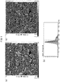
- FIG. 1(a) An AFM elastic modulus image of the obtained resin composite film is shown in Fig. 1(a) , an elastic modulus histogram is shown in Fig. 1(b) , and a binarized image is shown in Fig. 1(c) .
- the shaded area corresponds to the cellulose portions.
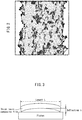
- Fig. 2 shows a processed image where the cellulose microfiber layer is defined as the region obtained by calculating the area due to the inorganic filler and the area due to the silica filler in the cellulose microfiber layer from modulus mapping of the resin composite film cross-section in Fig. 1(a) , using the image editing software "imageJ", selecting cellulose microfibers in at least 10 points nearest to the film outer surface, and connecting them with a line.
- F2-WS Fluorous copper foil
- the copper-clad laminate was immersed in a copper etching solution to remove the copper foil, to fabricate a thick resin composite film for evaluation, having a thickness of 0.8 mm.
- the prepreg was laminated onto both sides of the inner layer circuit board using a vacuum laminator by Meiki Co., Ltd. under conditions with a temperature of 120°C, a pressure of 7 kgf/cm 2 and an air pressure of ⁇ 5 mmHg, and then continuously hot pressed with a SUS end plate under conditions with a temperature of 120°C, a pressure of 5 kgf/cm 2 and atmospheric pressure. After then detaching the PET film, it was thermoset at 180°C for 30 minutes to form an insulating layer on both sides of the substrate.
- an aqueous solution of diethyleneglycol monobutyl ether: 200 ml/L and of NaOH: 5 g/L was prepared as a swelling solution and heated to 80°C, and immersion treatment was carried out for 5 minutes.
- an aqueous solution of KMnO 4 : 60 g/L and of NaOH: 40 g/L was prepared as a roughening solution and heated to 80°C, and immersion treatment was carried out for 15 minutes.
- An aqueous neutralizing solution (SnCl 2 : 30 g/L, HCl: 300 ml/L) was then prepared and heated to 40°C, and immersion treatment was carried out for 5 minutes for reduction of the KMnO 4 .
- Different resin composite films F4 (prepreg, resin composite film, copper-clad laminate, thick resin composite film, insulating layer laminate, roughened laminate, plating-treated laminate) were fabricated by the same method as Example 1, except that the cellulose microfiber sheet was S3, the varnish was V3, and the coating amount of the varnish was 0.1 g.
- the total light transmittance of the resin composite film was measured to be 82%.
- a varnish (V5) was coated to 0.8 g onto the release surface of a 20 cm-square polyethylene terephthalate support film (thickness: 16 ⁇ m) using a film applicator, and then the cellulose microfiber layered sheet (S5) cut to 10 cm-square was placed on it with the cellulose microfiber side in contact, and the varnish (V5) was recoated to 8.0 g on the cellulose microfiber sheet using an applicator.
- Different resin composite films F6 prepreg, resin composite film, copper-clad laminate, thick resin composite film, insulating layer laminate, roughened laminate, plating-treated laminate
- the cellulose microfiber sheet S6-attached polypropylene film was in turn placed on the release surface of a 20 cm-square polyethylene terephthalate support film (thickness: 16 ⁇ m), a 60 ⁇ m-thick polypropylene film was set over it with the cellulose microfiber sheet S6 facing the outer side, and it was covered with a separate polyethylene terephthalate support film (thickness: 16 ⁇ m) with the release surface in contact.
- the resin composite film F11 was laminated onto both sides of the inner layer circuit board fabricated in Example 1(5) using a vacuum laminator by Meiki Co., Ltd. under conditions with a temperature of 200°C, a pressure of 7 kgf/cm 2 and an air pressure of ⁇ 5 mmHg, and then continuously hot pressed with a SUS end plate under conditions with a temperature of 200°C, a pressure of 5 kgf/cm 2 and atmospheric pressure. The PET film was then detached and the circuit embedding property alone was evaluated.
- a resin composite film was produced with reference to Example 4 of Japanese Unexamined Patent Publication No. 2006-316253 .
- One sheet of the varnish RV1 obtained in Varnish Production Comparative Example 1 impregnated in the cellulose nonwoven fabric RS1 obtained in Sheet Production Comparative Example 1 (impregnation time: ⁇ 5 minutes) was thermoset in a hot press machine at a temperature of 100°C and a pressure of 9.81 MPa (curing time: 1 hour), to fabricate resin composite film RF1.
- Resin composite films prepreg, copper-clad laminate, evaluation substrate, insulating layer laminate, roughened laminate, plating-treated laminate
- Example 1 Sheet Prod.
- Example 2 Sheet Prod.
- Example 3 Sheet Prod.
- Example 4 Sheet Prod.
- Example 5 Sheet Prod.
- Example 6 Sheet Prod.
- Example 7 Sheet Prod.
- Example 8 Sheet Prod.
- Example 1 pts by wt 100 100 100 Slurry Prod.
- Example 3 pts by wt 100 Slurry Prod.
- Example 4 pts by wt 50 30 Slurry Prod.
- Example 5 pts by wt 50 Slurry Prod.
- Example 6 pts by wt 50 Slurry Prod.
- Example 7 pts by wt 100 Slurry Prod.
- Comparative Example 1 pts by wt 100 Production method Single-layer G G G G G G G G G G Nonwoven fabric layering G Calendering treatment G G G G G G Cellulose microfiber basis weight (charging) g/m 2 10 10 5 10 18 15 10 10 38 Physical properties Fiber sheet basis weight (measured) g/m 2 10 10 5 10 32 15 10 10 38 Fiber sheet thickness ⁇ m 17 17 5 17 135 40 10 55 100 Air permeability resistance sec/100ml 10 900 100 2000 6 20 1200 6 300 Void percentage % 61 50 43 61 86 75 45 81 75 Number average fiber diameter of cellulose microfiber layer nm 397 120 35 130 380 408 108 1502 65 Maximum fiber diameter cellulose microfiber layer ⁇ m 11 13 6 1.2 10 9 0.9 13 0.26 [Table
- Example 1 Varnish Prod.
- Example 2 Varnish Prod.
- Example 3 Varnish Prod.
- Example 4 Varnish Prod.
- Example 5 Varnish Prod.
- Example 6 Varnish Prod.
- Example 7 Varnish Prod.
- Example 8 Varnish Prod. Comp.
- the surface of a structure composed of cellulose microfibers was observed with a scanning electron microscope (SEM) at 10 random locations, at a magnification of 500x.
- the fiber diameter of the thickest fiber within the 10 SEM images was recorded as the maximum fiber diameter for the cellulose microfiber sheet.
- a layered sheet obtained by layering onto another nonwoven fabric was observed by SEM from the cellulose microfiber sheet side.
- Sheet basis weight g/m 2 Weight of 10 cm ⁇ square g / 0.01 m 2
- the thickness of a sample humidified in an atmosphere at 20°C room temperature, 50% RH was measured at 10 points using a surface contact-type meter (surface contact-type film thickness meter (Code No. 547-401) by Mitutoyo Corp.), and the average value was recorded as the thickness of the sample.
- the air permeability resistance of a sample humidified in an atmosphere at 23°C room temperature, 50% RH was measured at 10 points using an Oken-type air permeability resistance tester (Model EG01 by Asahi Seiko Co., Ltd.), and the average value was recorded as the air permeability resistance of the sample.
- Tencel cut filaments (3 mm lengths), as regenerated cellulose fibers acquired from Sojitz Corp., were placed in a washing net, a surfactant was added, and the mixture was washed with water several times in a washing machine to remove the oil agent on the fiber surfaces.
- the refined Tencel fibers (cut filaments) were dispersed in water (400 L) to a solid content of 1.5 wt%, and a Model SDR14 Lab Refiner (pressurized disc type) by Aikawa Iron Works Co. was used as a disc refiner apparatus for beating treatment of 400 L of the aqueous dispersion for 20 minutes with a disc clearance of 1 mm. Beating treatment was then continued under conditions with the clearance reduced to a level of essentially zero.
- CSF method Canadian Standard Freeness test method
- the obtained beaten aqueous dispersion was directly subjected to micronization treatment 5 times using a high-pressure homogenizer (NS015H by Niro Soavi) at an operating pressure of 100 MPa, to obtain a cellulose micro fiber slurry (solid concentration: 1.5 wt%).
- Linter pulp was used as natural cellulose for the starting material.
- the linter pulp was immersed in water to 4 wt% and heat treated in an autoclave at 130°C for 4 hours, and the obtained swollen pulp was washed with water several times to obtain water-impregnated swollen pulp.
- disc refiner and high-pressure homogenizer treatment were carried out by the same method as Production Example 1, to obtain a cellulose microfiber slurry (solid concentration: 1.5 wt%).
- the CSF value was 100 ml or greater.
- a cellulose microfiber slurry (solid concentration: 1.5 wt%) was obtained by the same method as Slurry Production Example 2, except for changing the starting material to abaca pulp.
- the CSF value was 630 ml or greater.
- a cellulose microfiber slurry (solid concentration: 1.5 wt%) was obtained by the same method as Slurry Production Example 2, except that the micronization treatment at an operating pressure of 100 MPa was carried out 30 times.
- An aramid microfiber slurry (solid concentration: 1.5 wt%) was obtained by the same method as Slurry Production Example 4, except that the micronization treatment at an operating pressure of 100 MPa was carried out 30 times.
- a cellulose microfiber slurry (solid concentration: 1.5 wt%) was obtained by the same method as Slurry Production Example 1, except that treatment was interrupted when the CSF value reached zero.
- a sheet was produced with reference to Example 4 of Japanese Unexamined Patent Publication No. 2006-316253 .
- a polysaccharide production medium containing 2.0% glucose (Polysaccharide-production-medium, Akihiko Shimada, Vivaorigino, 23, 1, 52-53, 1995 ) was subjected to high-pressure steam sterilization treatment, after which 1000 L thereof was placed in a 3000 L-capacity fermenter, strain CF-002 was inoculated to 104 CFU/ml, and agitation culture was carried out under aeration at 30°C for 2 days, to obtain a dispersion containing a large amount of bacterial cellulose (BC).
- BC bacterial cellulose
- the slurry of Slurry Production Example 1 was diluted to a solid concentration of 0.2 wt% and stirred for 3 minutes with a household mixer to prepare 312.5 g of a paper-making slurry.
- a PET/nylon mixed spun plain woven fabric (NT20 by Shikishima Canvas Co., Ltd., water permeation: 0.03 ml/(cm 2 ⁇ s) at 25°C in air, able to filter cellulose microfibers to 99% or greater by filtration at atmospheric pressure, 25°C) was set in a batch paper machine (automatic square sheet machine by Kumagai Riki Kogyo Co., Ltd., 25 cm ⁇ 25 cm, 80 mesh), and then the previously prepared paper-making slurry was loaded in an amount for a cellulose sheet with a basis weight of 10 g/m 2 , and paper-making (dewatering) was carried out with pressure reduction of 4 KPa with respect to atmospheric pressure.
- the wet web comprising the wet concentrated composition on the obtained filter cloth was detached from the wire and pressed for 1 minute at a pressure of 1 kg/cm 2 , after which the wet web surface was contacted with the drum surface of a drum dryer set to a surface temperature of 130°C, in a wet web/filter cloth two-layer state, and dried for about 120 seconds in a manner so as to keep the wet web in contact with the drum surface.
- the filter cloth was detached from the cellulose sheet structure of the obtained dried two-layer sheet, to obtain a white cellulose microfiber sheet (25 cm ⁇ 25 cm, 10 g/m 2 ).
- the cellulose microfiber sheet was subjected to smoothing treatment with a calender apparatus (hydraulic two-roll test embossing machine by Yuri Roll Machine Co., Ltd., upper roll: metal/lower roll: aramid, surface length: 300 mm, temperature: room temperature, pressure: 1.5 ton/300 mm), to obtain a thin-layer cellulose microfiber sheet S1.
- a calender apparatus hydroaulic two-roll test embossing machine by Yuri Roll Machine Co., Ltd., upper roll: metal/lower roll: aramid, surface length: 300 mm, temperature: room temperature, pressure: 1.5 ton/300 mm
- the sheet was sandwiched between two SUS metal frames (25 cm ⁇ 25 cm), anchored with a clip, and subjected to heat treatment in an oven at 160°C for 2 minutes, to obtain an opalescent cellulose microfiber sheet S4 containing aramid microfibers crosslinked with a blocked polyisocyanate.
- paper-making was carried out with a cupra long filament nonwoven fabric (trade name: BEMLIESE SN140 by Asahi Kasei Fibers Corp., basis weight: 14 g/m 2 , film thickness: 70 ⁇ m, density: 0.2 g/cm 3 , average monofilament size: 0.2 dtex) layered over a PET/nylon mixed spun plain weave fabric, to prepare a fiber sheet S5 having a cellulose microfiber sheet layered on a cupra long filament nonwoven fabric. No smoothing step was carried out.
- a cupra long filament nonwoven fabric trade name: BEMLIESE SN140 by Asahi Kasei Fibers Corp., basis weight: 14 g/m 2 , film thickness: 70 ⁇ m, density: 0.2 g/cm 3 , average monofilament size: 0.2 dtex
- the dry sheet was sandwiched between two SUS metal frames (25 cm ⁇ 25 cm), anchored with a clip, and subjected to heat treatment in an oven at 160°C for 2 minutes, to obtain a white cellulose microfiber sheet S7 containing cellulose microfibers crosslinked with a blocked polyisocyanate.
- the dispersion with a cellulose concentration of 1.0 wt% obtained in Slurry Production Comparative Example 1 was diluted with water to a cellulose concentration of 0.40 wt% and again subjected to dispersion treatment for 5 minutes with a household mixer, and the obtained dispersion was used as a paper-making dispersion.
- the obtained wet web was further covered with the same filter cloth and dewatered with metal rollers, to adjust the cellulose concentration to 12 to 13 wt%.
- the wet web sandwiched between filter cloths was placed on a metal sheet, a deadweight was set on it for drying to a fixed length, and it was set in a drying oven and dried at 100°C for 50 minutes. After drying, the nonwoven fabric was detached from the filter cloth to obtain a white cellulose sheet RS1.
- a varnish (V1) with a solid content of 70 wt% was prepared using methyl ethyl ketone as the solvent and the following compounds, mixed with a kneader.
- Varnish V2 was produced by the same method as Varnish Production Example 1, except for adding 98 parts by weight of spherical silica SO25R (Admatechs Co., Ltd., weight-average particle diameter: 0.5 ⁇ m).
- a varnish (V3) with a solid content of 70 wt% was prepared using methyl ethyl ketone as the solvent and the following compounds, mixed with a kneader.
- a varnish (V4) with a solid content of 70 wt% was prepared using methyl ethyl ketone as the solvent and the following compounds, mixed with a kneader.
- a varnish (V5) with a solid content of 70 wt% was prepared using methyl ethyl ketone as the solvent and the following compounds in admixture.
- a varnish (V6) with a solid content of 70 wt% was prepared using methyl ethyl ketone as the solvent and the following compounds, mixed with a kneader.
- Varnish Production Examples 1 to 6 and Varnish Production Comparative Example 1 are shown in Table 5 below.
- the numerical values for each of the components in Table 5 are parts by weight.
- the physical properties of the resin composite films were measured by the following methods.
- the X-ray diffraction pattern was confirmed to have one peak at 10° ⁇ 2 ⁇ ⁇ 19° and two peaks at 19° ⁇ 2 ⁇ ⁇ 30°. This identified the microfibers as either natural cellulose or regenerated cellulose.
- the cross-section sample of the resin composite film was fixed onto a special sample fixing stage, and the elastic modulus of the cross-section was measured under the following AFM measurement conditions.
- modulus mapping was carried out according to the modulus mapping of Example 1 described below.
- the filling factor of the cellulose microfibers in the film cross-section was calculated at 10 locations using the method described above, and the average value of 8 points, excluding the maximum and minimum values, was recorded as the filling factor of the cellulose microfibers for the entire film.
- the average fiber diameter of the cellulose microfibers in the film cross-section was calculated at 10 locations using the method described above, and the average value of 8 points, excluding the maximum and minimum values, was recorded as the average fiber diameter of the cellulose microfibers for the entire film.
- Particle analysis was conducted with the image editing software "imageJ" for the modulus mapping at 10 locations with all of the resin composite film cross-sections visible, and the particle diameters were calculated assuming the cellulose microfiber diameters to be perfect circles. The largest particle diameter was used as the maximum fiber diameter of the cellulose microfibers.
- the filling factor of the inorganic filler in the resin composite film was defined as the area ratio of the resin composite film cross-section occupied by the atoms composing the inorganic filler.
- Si was measured for silica particles
- Al was measured for aluminum hydroxide particles.
- the measuring method will now be explained, using silica particles as an example.
- a "HITACHI S-4800" scanning electron microscope product of Hitachi High-Tech Fielding Corp.
- the filling factor of the inorganic filler in the film cross-section was determined at 10 locations using the method described above, and the average value of 8 points, excluding the maximum and minimum values, was recorded as the average filling factor of the inorganic filler in the resin composite film.
- binarization refers to binarization based on the difference in the elements of the organic material (resin or fibers) and inorganic material (inorganic filler).
- the proportion of the inorganic filler in the cellulose microfiber layer was determined by the following formula.
- the cellulose microfiber layer is defined as the region delineated by selecting at least 10 points in order from the edge of the cellulose microfiber sheet near the outer surface of the film and connecting them with a line.
- Proportion of inorganic filler in cellulose microfiber layer % area of inorganic filler in cellulose microfibers/total area of inorganic filler in resin composite film ⁇ 100
- the proportion of the inorganic filler in the cellulose microfiber layer in the resin composite film cross-section was calculated at 10 locations using the method described above, and the average value of 8 points, excluding the maximum and minimum values, was recorded as the proportion of the inorganic filler in the cellulose microfiber layer.
- the length from the outer surface of the resin composite film to the surface of the nonwoven fabric layer is defined as the overcoat resin layer.
- the nonwoven fabric layer is defined as the layer comprising organic fibers, including the cellulose microfiber layer.
- AFM modulus mapping it can be confirmed to be composed of 3 layers: epoxy layer (front)/nonwoven fabric layer/epoxy layer (back).
- the length from the outer surface of the film to the surface of the nonwoven fabric layer is measured at 10 points each on the front and back, and the average values are recorded as the overcoat resin layer thickness (front) and the overcoat resin layer thickness (back).
- the obtained resin composite film was cut to 4 mm width ⁇ 30 mm length as a measuring sample. It was measured using an EXSTAR TMA6100 viscoelasticity meter (SII Nanotechnology, Inc.) in tension mode with a chuck distance of 20 mm and a frequency of 1 Hz, under a nitrogen atmosphere, raising the temperature from room temperature to 200°C at 5°C/min, lowering the temperature from 200°C to 25°C at 5°C/min, and then again raising the temperature from 25°C to 200°C at 5°C/min.
- the storage elastic modulus (E'150, E'200) was determined at 150°C and 200°C during the 2nd temperature increase.
- storage elastic modulus change rate E ′ 150 /E ′ 200 .
- the storage elastic modulus is lower at higher temperature (E'150 > E'200), and therefore the storage elastic modulus change rate is 1 or greater. A value closer to 1 may be considered lower change in storage elastic modulus at high temperature, and thus the material exhibits higher heat resistance.
- the resin composite film was cut to 3 mm width ⁇ 25 mm length as a measuring sample. It was measured using a model SII TMA6100 in tension mode with a chuck distance of 10 mm and load of 5 g, under a nitrogen atmosphere, raising the temperature from room temperature to 200°C at 5°C/min, lowering the temperature from 200°C to 25°C at 5°C/min, and then again raising the temperature from 25°C to 200°C at 5°C/min.
- the coefficient of linear thermal expansion (CTE150, CTE200) was determined at 150°C and 200°C during the 2nd temperature increase.
- CTE150 and CTE200 are the linear expansion coefficients at 1°C ranges of 149°C to 150°C and 199°C to 200°C, respectively, and they are expressed by the following formulas.
- CTE 150 L 150 ⁇ L 149 /L 100 ⁇ 10 6
- CTE 200 L 200 ⁇ L 199 /L 200 ⁇ 10 6
- L149, L150, L199 and L200 Chuck distance lengths at 149°C, 150°C, 199°C and 200°C.
- CTE difference CTE 200 ⁇ CTE 150
- An EXSTAR TMA6100 viscoelasticity meter (SII Nanotechnology, Inc.) was used to measure the Tg of the resin composite film. It was measured in tension mode with a chuck distance of 20 mm and a frequency of 1 Hz, under a nitrogen atmosphere, raising the temperature from room temperature to 200°C at 5°C/min, lowering the temperature from 200°C to 25°C at 5°C/min, and then again raising the temperature from 25°C to 200°C at 5°C/min.
- the Tg was defined as the intersection between the baseline at the 2nd temperature increase, and the tangent line at the inflection point (the point where the upward convex curve changes to a lower convex curve).
- the thickness was measured at 10 points in the prepreg, and the average value was recorded as the film thickness of the prepreg.
- a surface contact-type meter (surface contact-type film thickness meter (Code No. 547-401) by Mitutoyo Co.) was used as the film thickness meter.
- the thickness of the obtained resin composite film was measured at 10 points and the average value was recorded as the film thickness.
- a surface contact-type meter (surface contact-type film thickness meter (Code No. 547-401) by Mitutoyo Co.) was used as the film thickness meter.
- a plating-treated laminate was exposed to low temperature (-55°C) and high temperature (125°C) for 30 minutes each using a thermal shock device (TSA-71S-A/W by Espec), based on MIL-STD-883E conditions A (-55°C to 125°C), and 200 such cycles were conducted.
- TSA-71S-A/W by Espec thermal shock device
- MIL-STD-883E conditions A -55°C to 125°C
- the condition of failure of the copper wiring or the copper/resin interface was observed using an optical microscope photograph (transmitted light, magnification: 25x to 100x) and a cross-sectional SEM (magnification 5000x), and an organoleptic evaluation was carried out based on the following scale. Sections with peeling or blistering of the wiring, or cracking, were defined as failure locations, and a lower number of failure locations was evaluated as superior adhesiveness.
- Varnish V1 was coated to 0.3 g onto the release surface of a 20 cm-square polyethylene terephthalate support film (thickness: 16 ⁇ m) using a film applicator, and then the cellulose microfiber sheet (S 1) cut to 10 cm-square was placed on it, and the varnish V1 was recoated to 0.3 g on the cellulose microfiber sheet using an applicator.
- the obtained film was heated to 100°C for 4 minutes to remove the solvent and obtain a semi-cured prepreg.
- Fig. 2 shows a processed image where the cellulose microfiber layer is defined as the region obtained by calculating the area due to the inorganic filler and the area due to the silica filler in the cellulose microfiber layer from modulus mapping of the resin composite film cross-section in Fig. 1(a) , using the image editing software "imageJ", selecting at least 10 points at the edge of the cellulose microfiber sheet near the film outer surface, and connecting them with a line.
- F2-WS Fluorous copper foil
- the prepreg was laminated onto both sides of the inner layer circuit board using a vacuum laminator by Meiki Co., Ltd. under conditions with a temperature of 120°C, a pressure of 7 kgf/cm 2 and an air pressure of ⁇ 5 mmHg, and then continuously hot pressed with a SUS end plate under conditions with a temperature of 120°C and a pressure of 5 kgf/cm 2 , under atmospheric pressure. After then detaching the PET film, it was thermoset at 180°C for 30 minutes to form an insulating layer on both sides of the substrate.
- an aqueous solution of diethyleneglycol monobutyl ether: 200 ml/L and of NaOH: 5 g/L was prepared as a swelling solution and heated to 80°C, and immersion treatment was carried out for 5 minutes.
- an aqueous solution of KMnO 4 : 60 g/L and of NaOH: 40 g/L was prepared as a roughening solution and heated to 80°C, and immersion treatment was carried out for 15 minutes.
- An aqueous neutralizing solution (SnCl 2 : 30 g/L, HCl: 300 ml/L) was then prepared and heated to 40°C, and immersion treatment was carried out for 5 minutes for reduction of the KMnO 4 .
- Different resin composite films F4 (prepreg, resin composite film, copper-clad laminate, thick resin composite film, insulating layer laminate, roughened laminate, plating-treated laminate) were fabricated by the same method as Example 1, except that the cellulose microfiber sheet was S3, the varnish was V3, and the coating amount of the varnish was 0.1 g.
- the total light transmittance of the resin composite film was measured to be 82%.
- a varnish (V5) was coated to 0.8 g onto the release surface of a 20 cm-square polyethylene terephthalate support film (thickness: 16 ⁇ m) using a film applicator, and then the cellulose microfiber layered sheet (S5) cut to 10 cm-square was placed on it with the cellulose microfiber side in contact, and the varnish (V5) was recoated to 8.0 g on the cellulose microfiber sheet using an applicator.
- Different resin composite films F6 prepreg, resin composite film, copper-clad laminate, thick resin composite film, insulating layer laminate, roughened laminate, plating-treated laminate
- Slurry Production Example 3 was used for paper-making and fabrication of a wet web by the method of Sheet Production Example 1. Next, exchange was performed 5 times with isopropanol to prepare an isopropanol dispersion of the cellulose microfibers, and finally the isopropanol was removed by vacuum filtration.
- the obtained cellulose microfiber sheet was added to varnish V1 and mixed with a vacuum kneader. The obtained mixture was coated at 1 g onto the release surface of a 20 cm-square polyethylene terephthalate support film (thickness: 16 ⁇ m) using an applicator. The obtained film was heated to 100°C for 10 minutes in a vacuum to remove the solvent and obtain a semi-cured prepreg.
- Different resin composite films F7 prepreg, resin composite film, copper-clad laminate, thick resin composite film, insulating layer laminate, roughened laminate, plating-treated laminate
- Example 1 Different resin composite films F7 (prepreg, resin composite film, copper-clad laminate, thick resin composite film,
- a resin composite film was produced with reference to Example 4 of Japanese Unexamined Patent Publication No. 2006-316253 .
- One sheet of the varnish RV1 obtained in Varnish Production Comparative Example 1 impregnated in the cellulose nonwoven fabric RS-1 obtained in Sheet Production Comparative Example 1 (impregnation time: ⁇ 5 minutes) was thermoset in a hot press machine at a temperature of 100°C and a pressure of 9.81 MPa (curing time: 1 hour), to fabricate resin composite film RF1.
- copper-clad laminate and thick resin composite film fabrication, insulating layer formation, roughening treatment and plating treatment were carried out by the same methods as Example 1.
- Example 1 Sheet Prod.
- Example 2 Sheet Prod.
- Example 3 Sheet Prod.
- Example 4 Sheet Prod.
- Example 5 Sheet Prod.
- Example 6 Sheet Prod.
- Example 7 Sheet Prod.
- Example 2 pts by wt 50 70 Slurry Prod.
- Example 3 pts by wt 100 Slurry Prod.
- Example 4 pts by wt 50 30 Slurry Prod.
- Example 5 pts by wt 50 Slurry Prod.
- Example 6 pts by wt 50 Slurry Prod.
- Example 7 pts by wt 100 Slurry Prod.
- Comparative Example 1 pts by wt 100 Production method Single-layer G G G G G G G G Nonwoven fabric layering G Calendering treatment G G G G G G Cellulose microfiber basis weight (charging) g/m 2 10 10 5 10 18 10 10 38 Physical properties Sheet basis weight (measured) g/m 2 10 10 5 10 32 10 10 38 Sheet thickness ⁇ m 17 17 5 17 135 10 55 100 Air permeability resistance sec/100ml 10 900 100 2000 6 1200 6 300 Void percentage % 61 50 43 61 86 45 81 75 Number average fiber diameter of cellulose microfibers nm 397 120 35 130 380 108 1502 65 Maxium fiber diameter of cellulose microfibers ⁇ m 11 13 6 1.2 10 0.9 13 0.26 [Table 5] Varnish Prod.
- Example 7 is not according to the invention.
- the surfaces of cellulose micro fibers in the fiber sheet were observed with a scanning electron microscope (SEM) at 10 random locations, at a magnification corresponding to 1,000x to 100,000x, according to the fiber diameters of the microfibers.
- SEM scanning electron microscope
- a line was drawn on the obtained SEM image in the direction perpendicular to the horizontal direction of the image plane, the diameters of fibers intersecting the line were measured from the magnified image, and the number of intersecting fibers and the diameters of the fibers were counted.
- the number-average fiber diameter was thus calculated using the measurement results for a horizontal/vertical system in each image.
- the number-average fiber diameter was calculated in the same manner for two more extracted SEM images, and the results for a total of 10 images were averaged.
- the surface of the fiber sheet was observed with a scanning electron microscope (SEM) at 10 random locations, at a magnification of 500x.
- the fiber diameter of the thickest fiber within the 10 SEM images was recorded as the maximum fiber diameter for the fiber sheet.
- a multilayer structure obtained by layering onto another nonwoven fabric or the like was observed by SEM from the fiber sheet side.
- the thickness of a sample humidified in an atmosphere at 20°C room temperature, 50% RH was measured at 10 points using a surface contact-type meter (surface contact-type film thickness meter (Code No. 547-401) by Mitutoyo Corp.), and the average value was recorded as the thickness of the sample.
- the air permeability resistance of a sample humidified in an atmosphere at 23°C room temperature, 50% RH was measured at 10 points using an Oken-type air permeability resistance tester (Model EG01 by Asahi Seiko Co., Ltd.), and the average value was recorded as the air permeability resistance of the sample.
- the prepreg was impregnated with methyl ethyl ketone to dissolve the resin component, and the cellulose microfibers were dispersed. The dispersion was then subjected to vacuum filtration (pressure reduction: -0.09 MPa (absolute degree of vacuum: 10 kPa)).
- the filter used was a KG-90 by Advantech, Inc., with a 1.0 ⁇ m-diameter PTFE membrane filter (effective filtration area: 48 cm 2 ) also by Advantech, Inc. on the glass filter.
- the cellulose fibers accumulated on the PTFE membrane filter were dried in an oven at 120°C to obtain a film made of cellulose fibers. The number-average fiber diameter and maximum fiber diameter of the film were calculated using the following SEM observation method.
- a multilayer structure obtained by layering onto a nonwoven fabric or the like was observed by SEM from the cellulose micro fiber sheet side.
- the X-ray diffraction pattern was confirmed to have one peak at 10° ⁇ 2 ⁇ ⁇ 19° and two peaks at 19° ⁇ 2 ⁇ ⁇ 30°. This identified the microfibers as either natural cellulose or regenerated cellulose.
- the cross-section sample of the resin composite film was fixed onto a special sample fixing stage, and the elastic modulus of the cross-section was measured under the following AFM measurement conditions.
- the filling factor for the cellulose micro fiber sheet was defined as the area ratio of the cellulose microfiber sheet occupying the entire resin composite film in an AFM elastic modulus image of the resin composite film cross-section.
- the elastic modulus differs for different materials, and modulus mapping was performed for each material in the resin composite film by setting the threshold value for the histogram of the elastic modulus. For example, for a resin composite film composed entirely of cellulose microfibers and an epoxy, a contrast image is obtained for the epoxy (soft phase) and cellulose microfibers (hard phase). The histogram was largely divided into two peaks, and the midpoint between the two peaks of the histogram was set as the threshold value for binarization (cellulose: black, epoxy: white).
- the measurement was performed after first separating the cross-section of the resin composite film into multiple visual fields. Next, after preparing modulus mapping in each visual field, the images were joined to obtain an image with the resin composite film cross-section fitted into a single image. From modulus mapping with all of the resin composite film cross-sections visible, the area due to the cellulose microfiber sheet and the area of the entire film were calculated using the image editing software "imageJ", and finally the filling factor of the cellulose microfiber sheet was determined by the following formula.
- Cellulose microfiber sheet filling factor % area of cellulose microfiber sheet / entire film area ⁇ 100
- the filling factor of the cellulose microfiber sheet in the film cross-section was calculated at 10 locations using the method described above, and the average value of 8 points, excluding the maximum and minimum values, was recorded as the filling factor of the cellulose microfiber sheet for the entire film.
- the area ( ⁇ S f ) due to the cellulose microfiber sheet and the total length ( ⁇ L f ) of the interfaces between the cellulose microfiber sheet and other materials (epoxy, etc.) were calculated using the image editing software "imageJ", after which the average fiber diameter of the fibers constituting the cellulose microfiber sheet was calculated by the following formula.
- Average fiber diameter of fibres constituting cellulose microfiber sheet nm 4 ⁇ ⁇ S f / ⁇ L f
- the average fiber diameter of the fibers constituting the cellulose microfiber sheet in the resin composite film cross-section was calculated at 10 locations using the method described above, and the average value of 8 points, excluding the maximum and minimum values, was recorded as the average fiber diameter of the fibers constituting the cellulose microfiber sheet for the entire film.
- Particle analysis was conducted with the image editing software "imageJ" for the modulus mapping at 10 locations with all of the resin composite film cross-sections visible, and the particle diameters were calculated assuming the fiber diameters of the fibers constituting the cellulose microfiber sheet to be perfect circles. The largest particle diameter obtained from the analysis was used as the maximum fiber diameter of the fibers constituting the cellulose microfiber sheet.
- the filling factor of the inorganic filler in the resin composite film was defined as the area ratio of the resin composite film cross-section occupied by the atoms composing the inorganic filler.
- Si was measured for silica particles
- Al was measured for aluminum hydroxide particles.
- the measuring method will now be explained, using silica particles as an example.
- an S-4800 scanning electron microscope product of Hitachi High-Tech Fielding Corp. was used for imaging with a photograph magnification of 500x, an acceleration voltage of 1.0 kV and the detector set to secondary electrons, to obtain a cross-sectional SEM image.
- an energy dispersive X-ray detector (X-Max SILICON DRIFT X-RAY DETECTOR by Horiba, Ltd.) was used in the same visual field, to obtain element mapping for C and Si.
- the filling factor of the inorganic filler in the film cross-section was determined at 10 locations using the method described above, and the average value of 8 points, excluding the maximum and minimum values, was recorded as the average filling factor of the inorganic filler in the resin composite film.
- binarization refers to binarization based on the difference in the elements of the organic material (resin or fibers) and inorganic material (inorganic filler).
- the proportion of the inorganic filler in the cellulose microfiber layer was determined by the following formula.
- the cellulose microfiber layer is defined as the region delineated by selecting at least 10 points in order from the edge of the cellulose microfiber sheet near the outer surface of the film and connecting them with a line.
- Proportion of inorganic filler in cellulose microfiber layer (%) (area of inorganic filler in cellulose micro fibers/total area of inorganic filler in resin composite film) ⁇ 100
- the proportion of the inorganic filler in the cellulose microfiber layer in the resin composite film cross-section was calculated at 10 locations using the method described above, and the average value of 8 points, excluding the maximum and minimum values, was recorded as the proportion of the inorganic filler in the cellulose microfiber layer.
- the length from the outer surface of the resin composite film to the surface of the nonwoven fabric layer is defined as the overcoat resin layer.
- the nonwoven fabric layer is defined as the layer comprising organic fibers, including the cellulose microfiber layer.
- AFM modulus mapping it can be confirmed to be composed of 3 layers: epoxy layer (front)/nonwoven fabric layer/epoxy layer (back).
- the length from the outer surface of the film to the surface of the nonwoven fabric layer is measured at 10 points each on the front and back, and the average values are recorded as the overcoat resin layer thickness (front) and the overcoat resin layer thickness (back).
- the thickness of the resin composite film was measured at 10 points and the average value was recorded as the film thickness.
- a surface contact-type meter (surface contact-type film thickness meter (Code No. 547-401) by Mitutoyo Co.) was used as the film thickness meter.
- the resin composite film was cut to a 50 mm square and dried at 120°C for 2 hours and then the initial weight (W0) was measured, after which the weight (W1) after moisture absorption treatment under conditions of humidity: 85%/temperature: 85°C/192 hours was measured.
- the total light transmittance may be measured by an optical transparency test based on ASTM D1003, using an NDH7000SP CU2II (product name) haze meter (Nippon Denshoku Industries Co., Ltd.).
- a thick resin composite film with a thickness of 0.8 mm was cut out to a size of 1.5 (width) ⁇ 80 mm (length) for use as a measuring sample.
- the value at 1 GHz was measured by the cavity resonance method (Model 8722ES network analyzer, product of Agilent Technologies; cavity resonator, product of Kanto Electronics Application and Development Inc.).
- the interface portion (line segment) of the metal/insulating layer cross-sectional photograph was extracted by image processing.
- the fractal dimension (box count dimension) was calculated by the box count method, and the region size was set to 3 ⁇ m ⁇ 3 ⁇ m to allow evaluation of the complexity of the structure in the fine regions.
- the maximum cross-section height (Rt) of the exposed surface of the insulating layer of the insulating layer laminate was measured.
- the maximum cross-section height (Rt) of the insulating layer surface was determined using a non-contact surface roughness meter ("WYKO NT9300" by Veeco Instruments, Inc.), from the numerical value obtained with a 0.82 mm ⁇ 1.1 mm measurement range in VSI contact mode from a 10x lens.
- An Rt value of less than 2.5 ⁇ m was evaluated as "G”
- 2.5 ⁇ m or greater and less than 3 ⁇ m was evaluated as "F”
- 3 ⁇ m or greater was evaluated as "P”.
- G Good
- P Blistering, peeling or measling.
- CSF method Canadian Standard Freeness test method
- the obtained beaten aqueous dispersion was directly subjected to micronization treatment 5 times using a high-pressure homogenizer (NS015H by Niro Soavi) at an operating pressure of 100 MPa, to obtain a cellulose microfiber slurry (solid concentration: 1.5 wt%).
- Linter pulp was used as natural cellulose for the starting material.
- the linter pulp was immersed in water to 4 wt% and heat treated in an autoclave at 130°C for 4 hours, and the obtained swollen pulp was washed with water several times to obtain water-impregnated swollen pulp.
- disc refiner and high-pressure homogenizer treatment were carried out by the same method as Production Example 1, to obtain a cellulose microfiber slurry (solid concentration: 1.5 wt%).
- the CSF value was 100 ml or greater.
- a cellulose microfiber slurry (solid concentration: 1.5 wt%) was obtained by the same method as Slurry Production Example 2, except for changing the starting material to abaca pulp.
- the CSF value was 630 ml or greater.
- An aramid microfiber slurry (solid concentration: 1.5 wt%) was obtained by the same method as Slurry Production Example 1, except for changing the starting material to aramid fiber (1 mm length) by Teijin, Ltd.
- An aramid microfiber slurry (solid concentration: 1.5 wt%) was obtained by the same method as Slurry Production Example 4, except that the micronization treatment at an operating pressure of 100 MPa was carried out 30 times.
- a cellulose microfiber slurry (solid concentration: 1.5 wt%) was obtained by the same method as Slurry Production Example 1, except that treatment was interrupted when the CSF value reached zero.
- the wet web comprising the wet concentrated composition on the obtained filter cloth was detached from the wire and pressed for 1 minute at a pressure of 1 kg/cm 2 , after which the wet web surface was contacted with the drum surface of a drum dryer set to a surface temperature of 130°C, in a wet web/filter cloth two-layer state, and dried for about 120 seconds in a manner so as to keep the wet web in contact with the drum surface.
- the filter cloth was detached from the cellulose sheet structure of the obtained dried two-layer sheet, to obtain a white cellulose microfiber sheet (25 cm ⁇ 25 cm, 10 g/m 2 ).
- the cellulose microfiber sheet was subjected to smoothing treatment with a calender apparatus (hydraulic two-roll test embossing machine by Yuri Roll Machine Co., Ltd., upper roll: metal/lower roll: aramid, surface length: 300 mm, temperature: room temperature, pressure: 1.5 ton/300 mm), to obtain a thin-layer cellulose microfiber sheet S1.
- a calender apparatus hydroaulic two-roll test embossing machine by Yuri Roll Machine Co., Ltd., upper roll: metal/lower roll: aramid, surface length: 300 mm, temperature: room temperature, pressure: 1.5 ton/300 mm
- the smoothed sheet was sandwiched between two SUS metal frames (25 cm ⁇ 25 cm), anchored with a clip, and subjected to heat treatment in an oven at 160°C for 2 minutes, to obtain an opalescent cellulose microfiber sheet S4 containing aramid microfibers crosslinked with a blocked polyisocyanate.
- paper-making was carried out with a cupra long filament nonwoven fabric (trade name: BEMLIESE SN140 by Asahi Kasei Fibers Corp., basis weight: 14 g/m 2 , film thickness: 70 ⁇ m, density: 0.2 g/cm 3 , average monofilament size: 0.2 dtex) layered over a PET/nylon mixed spun plain weave fabric, to prepare a fiber sheet S5 having a cellulose microfiber sheet layered on a cupra long filament nonwoven fabric. No smoothing step was carried out.
- a cupra long filament nonwoven fabric trade name: BEMLIESE SN140 by Asahi Kasei Fibers Corp., basis weight: 14 g/m 2 , film thickness: 70 ⁇ m, density: 0.2 g/cm 3 , average monofilament size: 0.2 dtex
- a sheet was produced with reference to Example 4 of Japanese Unexamined Patent Publication No. 2006-316253 .
- the slurry with a cellulose concentration of 1.0 wt% produced in Slurry Production Comparative Example 1 was diluted with water to a cellulose concentration of 0.40 wt% and again subjected to dispersion treatment for 5 minutes with a household mixer, and the obtained dispersion was used as a paper-making dispersion.
- the obtained wet web was further covered with the same filter cloth and dewatered with metal rollers, to adjust the cellulose concentration to 12 to 13 wt%.
- the wet web sandwiched between filter cloths was placed on a metal sheet, a deadweight was set on it for drying to a fixed length, and it was set in a drying oven and dried at 100°C for 50 minutes. After drying, the nonwoven fabric was detached from the filter cloth to obtain a white cellulose sheet RS1.
- a varnish (V1) with a solid content of 70 wt% was prepared using methyl ethyl ketone as the solvent and the following compounds, mixed with a kneader.
- Varnish V2 was produced by the same method as Varnish Production Example 1, except for adding 98 parts by weight of spherical silica SO25R (Admatechs Co., Ltd., weight-average particle diameter: 0.5 ⁇ m).
- a varnish (V3) with a solid content of 70 wt% was prepared using methyl ethyl ketone as the solvent and the following compounds, mixed with a kneader.
- a varnish (V4) with a solid content of 70 wt% was prepared using methyl ethyl ketone as the solvent and the following compounds, mixed with a kneader.
- a varnish (V5) with a solid content of 70 wt% was prepared using methyl ethyl ketone as the solvent and the following compounds, mixed with a kneader.
- a varnish (V6) with a solid content of 70 wt% was prepared using methyl ethyl ketone as the solvent and the following compounds, mixed with a kneader.
- a varnish was produced with reference to Example 4 of Japanese Unexamined Patent Publication No. 2006-316253 .
- the following compounds were heated to 120°C and mixed with a kneader to prepare a varnish (RV1) with a solid content of 100 wt%.
- Varnish Production Examples 1 to 6 and Varnish Production Comparative Example 1 are shown in Table 8 below.
- the numerical values for each of the components in Table 8 are parts by weight.
- Varnish V1 was coated to 0.3 g onto the release surface of a 20 cm-square polyethylene terephthalate support film (thickness: 16 ⁇ m) using a film applicator, and then the cellulose microfiber sheet (S 1) cut to 10 cm-square was placed on it, and the varnish V1 was recoated to 0.3 g on the cellulose microfiber sheet using an applicator.
- the obtained film was heated to 100°C for 4 minutes to remove the solvent and obtain a semi-cured prepreg.
- FIG. 1(a) An AFM elastic modulus image of the obtained resin composite film is shown in Fig. 1(a) , an elastic modulus histogram is shown in Fig. 1(b) , and a binarized image is shown in Fig. 1(c) .
- the shaded area corresponds to the cellulose portions.
- Fig. 2 shows a processed image where the cellulose microfiber layer is defined as the region obtained by calculating the area due to the inorganic filler and the area due to the silica filler in the cellulose microfiber layer from modulus mapping of the resin composite film cross-section in Fig. 1(a) , using the image editing software "imageJ", selecting cellulose microfibers in at least 10 points nearest to the film outer surface, and connecting them with a line.
- F2-WS Fluorous copper foil
- the prepreg was laminated onto both sides of the inner layer circuit board using a vacuum laminator by Meiki Co., Ltd. under conditions with a temperature of 120°C, a pressure of 7 kgf/cm 2 and an air pressure of ⁇ 5 mmHg, and then continuously hot pressed with a SUS end plate under conditions with a temperature of 120°C, a pressure of 5 kgf/cm 2 and atmospheric pressure. After then detaching the PET film, it was thermoset at 180°C for 30 minutes to form an insulating layer on both sides of the substrate.
- an aqueous solution of diethyleneglycol monobutyl ether: 200 ml/L and of NaOH: 5 g/L was prepared as a swelling solution and heated to 80°C, and immersion treatment was carried out for 5 minutes.
- an aqueous solution of KMnO 4 : 60 g/L and of NaOH: 40 g/L was prepared as a roughening solution and heated to 80°C, and immersion treatment was carried out for 15 minutes.
- An aqueous neutralizing solution (SnCl 2 : 30 g/L, HCl: 300 ml/L) was then prepared and heated to 40°C, and immersion treatment was carried out for 5 minutes for reduction of the KMnO 4 .
- Different resin composite films F4 (prepreg, resin composite film, copper-clad laminate, thick resin composite film, insulating layer laminate, roughened laminate, plating-treated laminate) were fabricated by the same method as Example 1, except that the cellulose microfiber sheet was S3, the varnish was V3, and the coating amount of the varnish was 0.1 g.
- the total light transmittance of the resin composite film was measured to be 82%.
- a varnish (V5) was coated to 0.8 g onto the release surface of a 20 cm-square polyethylene terephthalate support film (thickness: 16 ⁇ m) using a film applicator, and then the cellulose microfiber layered sheet (S5) cut to 10 cm-square was placed on it with the cellulose microfiber side in contact, and the varnish (V5) was recoated to 8.0 g on the cellulose microfiber sheet using an applicator.
- Different resin composite films F6 prepreg, resin composite film, copper-clad laminate, thick resin composite film, insulating layer laminate, roughened laminate, plating-treated laminate
- a resin composite film was produced with reference to Example 4 of Japanese Unexamined Patent Publication No. 2006-316253 .
- One sheet of the varnish RV-1 obtained in Varnish Production Comparative Example 1 impregnated in the cellulose nonwoven fabric RS-1 obtained in Sheet Production Comparative Example 1 (impregnation time: ⁇ 5 minutes) was thermoset in a hot press machine at a temperature of 100°C and a pressure of 9.81 MPa (curing time: 1 hour), to fabricate resin composite film RF-1.
- copper-clad laminate and thick resin composite film fabrication, insulating layer formation, roughening treatment and plating treatment were carried out by the same methods as Example 1.
- Example 1 Sheet Prod.
- Example 2 Sheet Prod.
- Example 3 Sheet Prod.
- Example 4 Sheet Prod.
- Example 5 Sheet Prod.
- Example 6 Sheet Prod.
- Example 7 Sheet Prod.
- Example 1 S1 S2 S3 S4 S5 S6 S7 RS1 Starting materials Slurry Prod.
- Example 1 pts by wt 100 100 Slurry Prod.
- Example 2 pts by wt 50 70 Slurry Prod.
- Example 3 pts by wt 100 Slurry Prod.
- Example 4 pts by wt 50 30 Slurry Prod.
- Example 5 pts by wt 50 Slurry Prod.
- Example 6 pts by wt 50 Slurry Prod.
- Example 7 pts by wt 100 Slurry Prod.
- Comparative Example 1 pts by wt 100 Production method Single-layer G G G G G G G G Nonwoven fabric layering G Calendering treatment G G G G G G Cellulose microfiber basis weight (charging) g/m 2 10 10 5 10 18 10 10 38 Physical properties Fiber sheet basis weight (measured) g/m 2 10 10 5 10 32 10 10 38 Fiber sheet thickness ⁇ m 17 17 5 17 135 10 55 100 Air permeability resistance sec/100ml 10 900 100 2000 6 1200 6 300 Void percentage % 61 50 43 61 86 45 81 75 Number average fiber diameter of cellulose microfiber layer nm 397 120 35 130 380 108 1502 65 Maximum fiber diameter of cellulose microfiber layer ⁇ m 11 13 6 1.2 10 0.9 13 0.26 [Table 8] Varnish Prod.
- Example 6 Varnish Prod. Comp.
- Example 1 F1 F2 F3 F4 F5 F6 F7 F8 RS1 Cellulose microfiber sheet Sheet used S1 S2 S1 S3 S4 S5 S6 S7 RF1 Num. 1 1 1 1 1 1 1 1 1 Varnish Varnish used V1 V1 V2 V3 V4 V5 V6 V1 RV1 Prepreg Prepreg thickness ⁇ m 23.3 24.2 70.7 7.2 35.6 157.5 24.9 102.0 115 Resin composite film Filling factor of fiber sheet calculated from AFM modulus mapping % 30 15 10 50 14 8 29 9 25 Average fiber diameter of cellulose microfiber layer calculated from AFM modulus mapping nm 408 125 392 34 122 370 101 1589 65 Maximum fiber diameter of cellulose microfiber layer calculated from AFM modulus mapping ⁇ m 12 12 10 5 1.3 9 0.8 13 0.26 Void percentage of cellulose microfiber layer calculated from AFM modulus mapping % 59 48 60 42 59 84 44 60 73 Resin composite film thickness ⁇ m 22.2 22.2 66.7 6.7 3
- the surfaces of cellulose micro fibers in the fiber sheet were observed with a scanning electron microscope (SEM) at 10 random locations, at a magnification corresponding to 1,000x to 100,000x, according to the fiber diameters of the microfibers.
- SEM scanning electron microscope
- a line was drawn on the obtained SEM image in the direction perpendicular to the horizontal direction of the image plane, the diameters of fibers intersecting the line were measured from the magnified image, and the number of intersecting fibers and the diameters of the fibers were counted.
- the number-average fiber diameter was thus calculated using the measurement results for a horizontal/vertical system in each image.
- the number-average fiber diameter was calculated in the same manner for two more extracted SEM images, and the results for a total of 10 images were averaged.
- the surface of the cellulose microfiber sheet was observed with a scanning electron microscope (SEM) at 10 random locations, at a magnification of 500x.
- the fiber diameter of the thickest fiber within the 10 SEM images was recorded as the maximum fiber diameter for the fiber sheet.
- a multilayer structure obtained by layering onto another nonwoven fabric or the like was observed by SEM from the fiber sheet side.
- the thickness of a sample humidified in an atmosphere at 20°C room temperature, 50% RH was measured at 10 points using a surface contact-type meter (surface contact-type film thickness meter (Code No. 547-401) by Mitutoyo Corp.), and the average value was recorded as the thickness of the sample.
- the air permeability resistance of a sample humidified in an atmosphere at 23°C room temperature, 50% RH was measured at 10 points using an Oken-type air permeability resistance tester (Model EG01 by Asahi Seiko Co., Ltd.), and the average value was recorded as the air permeability resistance of the sample.
- the thickness was measured at 10 points in the prepreg, and the average value was recorded as the film thickness of the prepreg.
- a surface contact-type meter (surface contact-type film thickness meter (Code No. 547-401) by Mitutoyo Co.) was used as the film thickness meter.
- the prepreg was impregnated with methyl ethyl ketone to dissolve the resin component, and the cellulose microfibers were dispersed. The dispersion was then subjected to vacuum filtration (pressure reduction: -0.09 MPa (absolute degree of vacuum: 10 kPa)).
- the filter used was a KG-90 by Advantech, Inc., with a 1.0 ⁇ m-diameter PTFE membrane filter (effective filtration area: 48 cm 2 ) also by Advantech, Inc. on the glass filter.
- the cellulose fibers accumulated on the PTFE membrane filter were dried in an oven at 120°C to obtain a film made of cellulose fibers. The number-average fiber diameter and maximum fiber diameter of the film were calculated using the following SEM observation method.
- a multilayer structure obtained by layering onto a nonwoven fabric or the like was observed by SEM from the cellulose micro fiber sheet side.
- the X-ray diffraction pattern was confirmed to have one peak at 10° ⁇ 2 ⁇ ⁇ 19° and two peaks at 19° ⁇ 2 ⁇ ⁇ 30°. This identified the microfibers as either natural cellulose or regenerated cellulose.
- the cross-section sample of the resin composite film was fixed onto a special sample fixing stage, and the elastic modulus of the cross-section was measured under the following AFM measurement conditions.
- the filling factor for the cellulose micro fiber sheet was defined as the area ratio of the cellulose microfiber sheet occupying the entire resin composite film in an AFM elastic modulus image of the resin composite film cross-section.
- the elastic modulus differs for different materials, and modulus mapping was performed for each material in the resin composite film by setting the threshold value for the histogram of the elastic modulus. For example, for a resin composite film composed entirely of cellulose microfibers and an epoxy, a contrast image is obtained for the epoxy (soft phase) and cellulose microfibers (hard phase). The histogram was largely divided into two peaks, and the midpoint between the two peaks of the histogram was set as the threshold value for binarization (cellulose: black, epoxy: white).
- the measurement was performed after first separating the cross-section of the resin composite film into multiple visual fields. Next, after preparing modulus mapping in each visual field, the images were joined to obtain an image with the resin composite film cross-section fitted into a single image. From modulus mapping with all of the resin composite film cross-sections visible, the area due to the cellulose microfiber sheet and the area of the entire film were calculated using the image editing software "imageJ", and finally the filling factor of the cellulose microfiber sheet was determined by the following formula.
- Cellulose microfiber sheet filling factor % area of cellulose microfiber sheet / entire film area ⁇ 100
- the filling factor of the cellulose microfiber sheet in the film cross-section was calculated at 10 locations using the method described above, and the average value of 8 points, excluding the maximum and minimum values, was recorded as the filling factor of the cellulose microfiber sheet for the entire film.
- the area ( ⁇ S f ) due to the cellulose microfiber sheet and the total length ( ⁇ L f ) of the interfaces between the cellulose microfiber sheet and other materials (epoxy, etc.) were calculated using the image editing software "imageJ", after which the average fiber diameter of the fibers constituting the cellulose microfiber sheet was calculated by the following formula.
- Average fiber diameter of fibers constituting cellulose microfiber sheet nm 4 ⁇ ⁇ S f / ⁇ L f
- the average fiber diameter of the fibers constituting the cellulose microfiber sheet in the resin composite film cross-section was calculated at 10 locations using the method described above, and the average value of 8 points, excluding the maximum and minimum values, was recorded as the average fiber diameter of the fibers constituting the cellulose microfiber sheet for the entire film.
- Particle analysis was conducted with the image editing software "imageJ" for the modulus mapping at 10 locations with all of the resin composite film cross-sections visible, and the particle diameters were calculated assuming the fiber diameters of the fibers constituting the cellulose microfiber sheet to be perfect circles. The largest particle diameter obtained from the analysis was used as the maximum fiber diameter of the fibers constituting the cellulose microfiber sheet.
- the filling factor of the inorganic filler in the resin composite film was defined as the area ratio of the resin composite film cross-section occupied by the atoms composing the inorganic filler.
- Si was measured for silica particles
- Al was measured for aluminum hydroxide particles.
- the measuring method will now be explained, using silica particles as an example.
- an S-4800 scanning electron microscope product of Hitachi High-Tech Fielding Corp. was used for imaging with a photograph magnification of 500x, an acceleration voltage of 1.0 kV and the detector set to secondary electrons, to obtain a cross-sectional SEM image.
- the filling factor of the inorganic filler in the film cross-section was determined at 10 locations using the method described above, and the average value of 8 points, excluding the maximum and minimum values, was recorded as the average filling factor of the inorganic filler in the resin composite film.
- the proportion of the inorganic filler in the cellulose microfiber layer was determined by the following formula.
- the cellulose microfiber layer is defined as the region delineated by selecting at least 10 points in order from the edge of the cellulose microfiber sheet near the outer surface of the film and connecting them with a line.
- Proportion of inorganic filler in cellulose microfiber layer (%) (area of inorganic filler in cellulose micro fibers/total area of inorganic filler in resin composite film) ⁇ 100
- the proportion of the inorganic filler in the cellulose microfiber layer in the resin composite film cross-section was calculated at 10 locations using the method described above, and the average value of 8 points, excluding the maximum and minimum values, was recorded as the proportion of the inorganic filler in the cellulose microfiber layer.
- the length from the outer surface of the resin composite film to the surface of the nonwoven fabric layer is defined as the overcoat resin layer.
- the nonwoven fabric layer is defined as the layer comprising organic fibers, including the cellulose microfiber layer.
- AFM modulus mapping it can be confirmed to be composed of 3 layers: epoxy layer (front)/nonwoven fabric layer/epoxy layer (back).
- the length from the outer surface of the film to the surface of the nonwoven fabric layer is measured at 10 points each on the front and back, and the average values are recorded as the overcoat resin layer thickness (front) and the overcoat resin layer thickness (back).
- the resin composite film was cut to 3 mm width ⁇ 25 mm length as a measuring sample. It was measured using a model SII TMA6100 in tension mode with a chuck distance of 10 mm and load of 5 g, under a nitrogen atmosphere, raising the temperature from room temperature to 200°C at 5°C/min, lowering the temperature from 200°C to 25°C at 5°C/min, and then again raising the temperature from 25°C to 200°C at 5°C/min.
- the coefficient of linear thermal expansion (CTE150 and CTE200) was determined at 150°C and 200°C during the 2nd temperature increase.
- CTE150 and CTE200 are the linear expansion coefficients at 1°C ranges of 149°C to 150°C and 199°C to 200°C, respectively, and they are expressed by the following formulas.
- CTE150 L 150 ⁇ L 149 / L 100 ⁇ 10 6
- CTE 200 L 200 ⁇ L 199 / L 200 ⁇ 10 6
- L149, L150, L199 and L200 are the chuck distance lengths at 149°C, 150°C, 199°C and 200°C, respectively.
- the thickness of the resin composite film was measured at 10 points and the average value was recorded as the film thickness.
- a surface contact-type meter (surface contact-type film thickness meter (Code No. 547-401) by Mitutoyo Co.) was used as the film thickness meter.
- the resin composite film was cut to a 50 mm square and dried at 120°C for 2 hours and then the initial weight (W0) was measured, after which the weight (W1) after moisture absorption treatment under conditions of humidity: 85%/temperature: 85°C/192 hours was measured.
- the total light transmittance may be measured by an optical transparency test based on ASTM D1003, using an NDH7000SP CU2II (product name) haze meter (Nippon Denshoku Industries Co., Ltd.).
- a thick resin composite film with a thickness of 0.8 mm was cut out to a size of 1.5 (width) ⁇ 80 mm (length) for use as a measuring sample.
- the value at 1 GHz was measured by the cavity resonance method (Model 8722ES network analyzer, product of Agilent Technologies; cavity resonator, product of Kanto Electronics Application and Development Inc.).
- a wiring pattern arranged with through-holes at 0.2 mm spacings was formed on a copper foil on both sides of a copper-clad laminate, a 10 V voltage was applied between adjacent through-holes in an atmosphere at a temperature of 120°C and a humidity of 85% RH, and the change in resistance value was measured.
- a resistance of less than 1 M ⁇ within 500 hours after starting the test was considered to be poor insulation, and the proportion of samples without poor insulation was evaluated (with a sample number of 10).
- Warping % Deflection h mm / length L mm ⁇ 100
- Fig. 3 is a conceptual drawing of the deflection (h) and length (L) of a thick resin composite film.
- a warping rate of ⁇ 1% was indicated as “G”
- ⁇ 2% was indicated as “F”
- ⁇ 2% was indicated as "P”.
- Tencel cut filaments (3 mm lengths), as regenerated cellulose fibers acquired from Sojitz Corp., were placed in a washing net, a surfactant was added, and the mixture was washed with water several times in a washing machine to remove the oil agent on the fiber surfaces.
- the refined Tencel fibers (cut filaments) were dispersed in water (400 L) to a solid content of 1.5 wt%, and a Model SDR14 Lab Refiner (pressurized disc type) by Aikawa Iron Works Co. was used as a disc refiner apparatus for beating treatment of 400 L of the aqueous dispersion for 20 minutes with a disc clearance of 1 mm. Beating treatment was then continued under conditions with the clearance reduced to a level of essentially zero.
- CSF method Canadian Standard Freeness test method
- the obtained beaten aqueous dispersion was directly subjected to micronization treatment 5 times using a high-pressure homogenizer (NS015H by Niro Soavi) at an operating pressure of 100 MPa, to obtain a cellulose microfiber slurry (solid concentration: 1.5 wt%).
- a cellulose microfiber slurry (solid concentration: 1.5 wt%) was obtained by the same method as Slurry Production Example 2, except that the micronization treatment at an operating pressure of 100 MPa was carried out 30 times.
- An aramid microfiber slurry (solid concentration: 1.5 wt%) was obtained by the same method as Slurry Production Example 4, except that the micronization treatment at an operating pressure of 100 MPa was carried out 30 times.
- a cellulose microfiber slurry (solid concentration: 1.5 wt%) was obtained by the same method as Slurry Production Example 1, except that treatment was interrupted when the CSF value reached zero.
- a slurry was produced with reference to Example 4 of Japanese Unexamined Patent Publication No. 2006-316253 .
- a polysaccharide production medium containing 2.0% glucose (Polysaccharide-production-medium, Akihiko Shimada, Vivaorigino, 23, 1, 52-53, 1995 ) was subjected to high-pressure steam sterilization treatment, after which 1000 L thereof was placed in a 3000 L-capacity fermenter, strain CF-002 was inoculated to 104 CFU/ml, and agitation culture was carried out under aeration at 30°C for 2 days, to obtain a dispersion containing a large amount of bacterial cellulose (BC).
- BC bacterial cellulose
- the slurry of Slurry Production Example 1 was diluted to a solid concentration of 0.2 wt% and stirred for 3 minutes with a household mixer to prepare 312.5 g of a paper-making slurry.
- a PET/nylon mixed spun plain woven fabric ⁇ NT20 by Shikishima Canvas Co., Ltd., water permeation: 0.03 ml/(cm 2 ⁇ s) at 25°C in air, able to filter cellulose microfibers to 99% or greater by filtration at atmospheric pressure, 25°C ⁇ was set in a batch paper machine (automatic square sheet machine by Kumagai Riki Kogyo Co., Ltd., 25 cm ⁇ 25 cm, 80 mesh), and then the previously prepared paper-making slurry was loaded in an amount for a cellulose sheet with a basis weight of 10 g/m 2 , and paper-making (dewatering) was carried out with pressure reduction of 4 KPa with respect to atmospheric pressure.
- the wet web comprising the wet concentrated composition set on the obtained filter cloth was detached from the wire and pressed for 1 minute at a pressure of 1 kg/cm 2 .
- the wet web surface was contacted with the drum surface of a drum dryer set to a surface temperature of 130°C, in a wet web/filter cloth two-layer state and dried for about 120 seconds in a manner so as to keep the wet web in contact with the drum surface.
- the filter cloth was detached from the cellulose sheet structure of the obtained dried two-layer sheet, to obtain a white cellulose microfiber sheet (25 cm ⁇ 25 cm, 10 g/m 2 ).
- the sheet was sandwiched between two SUS metal frames (25 cm ⁇ 25 cm), anchored with a clip, and subjected to heat treatment in an oven at 160°C for 2 minutes, to obtain an opalescent cellulose microfiber sheet S4 containing aramid microfibers crosslinked with a blocked polyisocyanate.
- paper-making was carried out with a cupra long filament nonwoven fabric (trade name: BEMLIESE SN140 by Asahi Kasei Fibers Corp., basis weight: 14 g/m 2 , film thickness: 70 ⁇ m, density: 0.2 g/cm 3 , average monofilament size: 0.2 dtex) layered over a PET/nylon mixed spun plain weave fabric, to prepare a fiber sheet S5 having a cellulose microfiber sheet layered on a cupra long filament nonwoven fabric. No smoothing step was carried out.
- a cupra long filament nonwoven fabric trade name: BEMLIESE SN140 by Asahi Kasei Fibers Corp., basis weight: 14 g/m 2 , film thickness: 70 ⁇ m, density: 0.2 g/cm 3 , average monofilament size: 0.2 dtex
- the dry sheet was sandwiched between two SUS metal frames (25 cm ⁇ 25 cm), anchored with a clip, and subjected to heat treatment in an oven at 160°C for 2 minutes, to obtain a white cellulose microfiber sheet S7 containing cellulose microfibers crosslinked with a blocked polyisocyanate.
- a sheet was produced with reference to Example 4 of Japanese Unexamined Patent Publication No. 2006-316253 .
- the slurry with a cellulose concentration of 1.0 wt% produced in Slurry Production Comparative Example 1 was diluted with water to a cellulose concentration of 0.40 wt% and again subjected to dispersion treatment for 5 minutes with a household mixer, and the obtained dispersion was used as a paper-making dispersion.
- the obtained wet web was further covered with the same filter cloth and dewatered with metal rollers, to adjust the cellulose concentration to 12 to 13 wt%.
- the wet web sandwiched between filter cloths was placed on a metal sheet, a deadweight was set on it for drying to a fixed length, and it was set in a drying oven and dried at 100°C for 50 minutes. After drying, the nonwoven fabric was detached from the filter cloth to obtain a white cellulose sheet RS1.
- a varnish (V1) with a solid content of 70 wt% was prepared using methyl ethyl ketone as the solvent and the following compounds, mixed with a kneader.
- Varnish V2 was produced by the same method as Varnish Production Example 1, except for adding 98 parts by weight of spherical silica SO25R (Admatechs Co., Ltd., weight-average particle diameter: 0.5 ⁇ m).
- a varnish (V3) with a solid content of 70 wt% was prepared using methyl ethyl ketone as the solvent and the following compounds, mixed with a kneader.
- a varnish (V4) with a solid content of 70 wt% was prepared using methyl ethyl ketone as the solvent and the following compounds, mixed with a kneader.
- a varnish (V5) with a solid content of 70 wt% was prepared using methyl ethyl ketone as the solvent and the following compounds, mixed with a kneader.
- a varnish was produced with reference to Example 4 of Japanese Unexamined Patent Publication No. 2006-316253 .
- the following compounds were heated to 120°C and mixed with a kneader to prepare a varnish (RV1) with a solid content of 100 wt%.
- Varnish Production Examples 1 to 6 and Varnish Production Comparative Example 1 are shown in Table 11 below.
- the numerical values for each of the components in Table 11 are parts by weight.
- Varnish V1 was coated to 0.3 g onto the release surface of a 20 cm-square polyethylene terephthalate support film (thickness: 16 ⁇ m) using a film applicator, and then the cellulose microfiber sheet (S1) cut to 10 cm-square was placed on it, and the varnish V1 was recoated to 0.3 g on the cellulose microfiber sheet using an applicator.
- the obtained film was heated to 100°C for 4 minutes to remove the solvent and obtain a semi-cured prepreg.
- Fig. 2 shows a processed image where the cellulose microfiber layer is defined as the region obtained by calculating the area due to the inorganic filler and the area due to the silica filler in the cellulose microfiber layer from modulus mapping of the resin composite film cross-section in Fig. 1(a) , using the image editing software "imageJ", selecting at least 10 points at the edge of the cellulose microfiber sheet near the film outer surface, and connecting them with a line.
- F2-WS Fluorous copper foil
- the copper-clad laminate was immersed in a copper etching solution to remove the copper foil, to fabricate a thick resin composite film for evaluation.
- Different resin composite films F4 (prepreg, resin composite film, copper-clad laminate, thick resin composite film) were fabricated by the same method as Example 1, except that the cellulose microfiber sheet was S3, the varnish was V3, and the coating amount of the varnish was 0.1 g.
- the total light transmittance of the resin composite film was measured to be 82%.
- a varnish (V5) was coated to 0.8 g onto the release surface of a 20 cm-square polyethylene terephthalate support film (thickness: 16 ⁇ m) using a film applicator, and then the cellulose microfiber layered sheet (S5) cut to 10 cm-square was placed on it with the cellulose microfiber side in contact, and the varnish (V5) was recoated to 8.0 g on the cellulose microfiber sheet using an applicator.
- Different resin composite films F6 prepreg, resin composite film, copper-clad laminate, thick resin composite film
- a resin composite film was produced with reference to Example 4 of Japanese Unexamined Patent Publication No. 2006-316253 .
- One sheet of the varnish RV1 obtained in Varnish Production Comparative Example 1 impregnated in the cellulose nonwoven fabric RS1 obtained in Sheet Production Comparative Example 1 (impregnation time: ⁇ 5 minutes) was thermoset in a hot press machine at a temperature of 100°C and a pressure of 9.81 MPa (curing time: 1 hour), to fabricate resin composite film RF1.
- copper-clad laminate and thick resin composite film fabrication were carried out by the same methods as Example 1.
- Example 1 Sheet Prod.
- Example 2 Sheet Prod.
- Example 3 Sheet Prod.
- Example 4 Sheet Prod.
- Example 5 Sheet Prod.
- Example 6 Sheet Prod.
- Example 7 Sheet Prod.
- Example 2 pts by wt 50 70 Slurry Prod.
- Example 3 pts by wt 100 Slurry Prod.
- Example 4 pts by wt 50 30 Slurry Prod.
- Example 5 pts by wt 50 Slurry Prod.
- Example 6 pts by wt 50 Slurry Prod.
- Example 7 pts by wt 100 Slurry Prod.
- Comparative Example 1 pts by wt 100 Production method Single-layer G G G G G G G G Nonwoven fabric layering G Calendering treatment G G G G G G Cellulose microfiber basis weight (charging) g/m 2 10 10 5 10 18 10 10 38 Physical properties Fiber sheet basis weight (measured) g/m 2 10 10 5 10 32 10 10 38 Fiber sheet thickness ⁇ m 17 17 5 17 135 10 55 100 Air permeability resistance sec/100ml 10 900 100 2000 6 1200 6 300 Void percentage % 61 50 43 61 86 45 81 75 Number average fiber diameter of micro cellulose fiber layer nm 397 120 35 130 380 108 1502 65 Maximum fiber diameter of micro cellulose fiber layer ⁇ m 11 13 6 1.2 10 0.9 13 0.26 [Table 11] Varnish Prod.
- Example 6 Varnish Prod. Comp.
- Example 1 F1 F2 F3 F4 F5 F6 F7 F8 RF1 Cellulose microfiber sheet Sheet used S1 S2 S1 S3 S4 S5 S6 S7 RS1 Num. 1 1 1 1 1 1 1 1 1 Varnish Varnish used V1 V1 V2 V3 V4 V5 V6 V1 RV1 Prepreg Prepreg thickness ⁇ m 23.3 24.2 70.7 7.2 35.6 158 24.9 102.0 115 Resin composite film Filling factor of fiber sheet calculated from AFM modulus mapping % 30 30 10 50 20 8 29 9 25 Average fiber diameter of cellulose microfiber layer calculated from AFM modulus mapping nm 408 125 392 34 122 370 101 1589 65 Maximum fiber diameter of cellulose microfiber layer calculated from AFM modulus mapping ⁇ m 12 12 10 5 1.3 9 0.8 13 0.26 Void percentage of cellulose microfiber layer calculated from AFM modulus mapping % 59 48 60 42 59 85 44 60 73 CTE150 ppm/°C 30 20 40 25 30 45 18 42 50
Landscapes
- Chemical & Material Sciences (AREA)
- Engineering & Computer Science (AREA)
- Materials Engineering (AREA)
- Manufacturing & Machinery (AREA)
- Health & Medical Sciences (AREA)
- Chemical Kinetics & Catalysis (AREA)
- Medicinal Chemistry (AREA)
- Polymers & Plastics (AREA)
- Organic Chemistry (AREA)
- Microelectronics & Electronic Packaging (AREA)
- Physics & Mathematics (AREA)
- Multimedia (AREA)
- Acoustics & Sound (AREA)
- Signal Processing (AREA)
- Condensed Matter Physics & Semiconductors (AREA)
- General Physics & Mathematics (AREA)
- Computer Hardware Design (AREA)
- Power Engineering (AREA)
- Laminated Bodies (AREA)
- Reinforced Plastic Materials (AREA)
- Diaphragms For Electromechanical Transducers (AREA)
- Production Of Multi-Layered Print Wiring Board (AREA)
Applications Claiming Priority (5)
| Application Number | Priority Date | Filing Date | Title |
|---|---|---|---|
| JP2016069808 | 2016-03-30 | ||
| JP2016069806 | 2016-03-30 | ||
| JP2016069810 | 2016-03-30 | ||
| JP2016069807 | 2016-03-30 | ||
| PCT/JP2017/013086 WO2017170781A1 (ja) | 2016-03-30 | 2017-03-29 | セルロース微細繊維層を含む樹脂複合フィルム |
Publications (3)
| Publication Number | Publication Date |
|---|---|
| EP3438166A1 EP3438166A1 (en) | 2019-02-06 |
| EP3438166A4 EP3438166A4 (en) | 2019-05-01 |
| EP3438166B1 true EP3438166B1 (en) | 2021-12-15 |
Family
ID=59965767
Family Applications (1)
| Application Number | Title | Priority Date | Filing Date |
|---|---|---|---|
| EP17775315.9A Active EP3438166B1 (en) | 2016-03-30 | 2017-03-29 | Resin composite film including cellulose microfiber layer |
Country Status (7)
| Country | Link |
|---|---|
| US (1) | US10703070B2 (enExample) |
| EP (1) | EP3438166B1 (enExample) |
| JP (2) | JP6626190B2 (enExample) |
| KR (1) | KR102245529B1 (enExample) |
| CN (1) | CN108884251B (enExample) |
| TW (1) | TWI643731B (enExample) |
| WO (1) | WO2017170781A1 (enExample) |
Families Citing this family (39)
| Publication number | Priority date | Publication date | Assignee | Title |
|---|---|---|---|---|
| CN106658307B (zh) * | 2016-12-26 | 2020-01-07 | 歌尔股份有限公司 | 一种振膜、其制作方法及包含该振膜的扬声器 |
| KR102427370B1 (ko) * | 2017-10-10 | 2022-07-29 | 유니티카 가부시끼가이샤 | 다공질 폴리이미드 필름 및 그의 제조 방법 |
| JP6933188B2 (ja) * | 2018-05-14 | 2021-09-08 | 味の素株式会社 | 封止用樹脂組成物層、支持体付き樹脂シート、封止用樹脂硬化層、半導体パッケージ及び半導体装置 |
| WO2019230616A1 (ja) * | 2018-06-01 | 2019-12-05 | 互応化学工業株式会社 | 感光性樹脂組成物、ドライフィルム、及びプリント配線板 |
| WO2019236866A1 (en) * | 2018-06-07 | 2019-12-12 | Powdermet, Inc. | Non-linear surfactant |
| KR102123098B1 (ko) * | 2018-06-15 | 2020-06-15 | (주)동성화인텍 | 친환경 복합재 파이프의 제조방법 및 그 파이프 |
| CN108877517B (zh) * | 2018-06-26 | 2020-11-06 | 深圳市华星光电技术有限公司 | 一种柔性可拉伸基板及其制备方法 |
| US11467182B1 (en) * | 2018-08-06 | 2022-10-11 | Vladimir Zhizhimontov | Scanning probe microscope with use of composite materials |
| KR102302203B1 (ko) * | 2018-11-29 | 2021-09-15 | 도레이첨단소재 주식회사 | 점착제 조성물, 점착필름 및 디스플레이 디바이스 |
| WO2020145354A1 (ja) * | 2019-01-09 | 2020-07-16 | 旭化成株式会社 | 多孔質微細セルロース繊維複合化シート |
| JP7327952B2 (ja) * | 2019-03-07 | 2023-08-16 | 旭化成株式会社 | 微細セルロース繊維を含む、分散体、構造体及び架橋構造体の製造方法 |
| CN110012394B (zh) * | 2019-03-26 | 2021-04-27 | 瑞声科技(新加坡)有限公司 | 振膜基材及其制备方法、振膜及扬声器 |
| CN110012655B (zh) * | 2019-04-28 | 2025-01-17 | 昆山雅森电子材料科技有限公司 | 具有emi功能的薄型化覆盖膜 |
| JP7328671B2 (ja) * | 2019-05-09 | 2023-08-17 | ナミックス株式会社 | 積層体 |
| CN110106534B (zh) * | 2019-05-15 | 2021-03-26 | 南京理工大学 | 一种制备具有木材镜面结构超疏水镍表面的方法 |
| JP7321781B2 (ja) * | 2019-06-04 | 2023-08-07 | 太陽ホールディングス株式会社 | 有機無機複合粒子を含む樹脂組成物、ドライフィルム、硬化物、電子部品 |
| CN110446143B (zh) * | 2019-07-05 | 2021-03-09 | 歌尔股份有限公司 | 发声装置的振膜以及发声装置 |
| CN110423369A (zh) * | 2019-09-12 | 2019-11-08 | 中国热带农业科学院农产品加工研究所 | 薄膜及其制备方法以及可降解地膜 |
| CN110669343A (zh) * | 2019-10-24 | 2020-01-10 | 广州赫尔普化工有限公司 | 一种耐磨导热硅橡胶复合材料及其制备方法 |
| CN112717731B (zh) * | 2019-10-29 | 2023-01-06 | 海南椰国食品有限公司 | 一种离子导电膜及其制备方法 |
| TWI715282B (zh) * | 2019-11-07 | 2021-01-01 | 國立宜蘭大學 | 以電紡技術固定化酵素製備時間溫度感應器的製作方法 |
| JPWO2021166847A1 (enExample) * | 2020-02-18 | 2021-08-26 | ||
| CN111479209B (zh) * | 2020-03-16 | 2021-06-25 | 东莞市古川胶带有限公司 | 一种扬声器振膜复合材料 |
| JP7283639B2 (ja) * | 2020-08-12 | 2023-05-30 | 住友ベークライト株式会社 | 離型フィルムおよび成型品の製造方法 |
| CN112497374A (zh) * | 2020-11-28 | 2021-03-16 | 无锡市森泰木制品有限公司 | 一种环保抗菌实木地板的制备方法 |
| CN112563518B (zh) * | 2020-12-11 | 2021-08-31 | 鸿基创能科技(广州)有限公司 | 制备高稳定性燃料电池催化剂涂布浆料的方法 |
| JP7464150B2 (ja) * | 2020-12-28 | 2024-04-09 | 株式会社Ihi | 繊維強化材における繊維層を識別する、識別装置、識別方法、及び、識別プログラム |
| CA3145718A1 (en) * | 2021-01-15 | 2022-07-15 | Innotech Alberta Inc. | Cellulose particle mold release layer |
| CN114318671B (zh) * | 2021-02-24 | 2023-06-30 | 福建龙美智慧医疗器械有限公司 | 一种吸湿抑菌的水刺无纺布的制备方法 |
| CN113265123A (zh) * | 2021-04-26 | 2021-08-17 | 苏州赛荣建筑装饰工程有限公司 | 一种可降解的保温塑料地膜及其制备方法 |
| CN113308005A (zh) * | 2021-05-28 | 2021-08-27 | 惠州市纵胜电子材料有限公司 | 一种高强度抗静电3d片材及其制备方法 |
| WO2023167283A1 (ja) * | 2022-03-02 | 2023-09-07 | 旭化成株式会社 | ガラスクロス、ガラスクロスの製造方法、プリプレグ、プリント配線板 |
| US11596066B1 (en) | 2022-03-22 | 2023-02-28 | Thintronics. Inc. | Materials for printed circuit boards |
| KR20230146284A (ko) | 2022-04-12 | 2023-10-19 | 현대자동차주식회사 | 투명도 및 강성이 뛰어난 복합 시트의 제조방법 |
| KR102893786B1 (ko) * | 2023-01-16 | 2025-12-01 | 한국원자력연구원 | 다공성 미소섬유상 셀룰로오스 필름 및 이의 제조방법 |
| WO2025053151A1 (ja) * | 2023-09-05 | 2025-03-13 | 王子ホールディングス株式会社 | 積層体 |
| TR2023012895A1 (tr) * | 2023-10-11 | 2025-04-21 | Istanbul Teknik Ueniversitesi | Teksti̇l tabanli bi̇r geri̇lebi̇li̇r tarakli sensör ve üreti̇m metodu |
| CN118440377B (zh) * | 2024-07-08 | 2024-09-03 | 四川大学 | 一种芳纶基高导热湿敏显色复合薄膜、制备方法及应用 |
| CN119545284A (zh) * | 2024-11-27 | 2025-02-28 | 国光电器股份有限公司 | 一种纸盆及其制备方法、包含其的扬声器 |
Family Cites Families (11)
| Publication number | Priority date | Publication date | Assignee | Title |
|---|---|---|---|---|
| JPS6083826A (ja) | 1983-10-14 | 1985-05-13 | Mitsubishi Electric Corp | Frpレド−ムの製造方法 |
| JPH02127593A (ja) * | 1988-11-07 | 1990-05-16 | Sanyo Kokusaku Pulp Co Ltd | 積層板原紙の製造方法 |
| JPH02276624A (ja) * | 1989-04-19 | 1990-11-13 | Sumitomo Bakelite Co Ltd | 熱硬化性樹脂積層板 |
| TWI391427B (zh) * | 2005-02-01 | 2013-04-01 | Pioneer Corp | 纖維強化複合材料及其製造方法與用途,以及纖維素纖維集合體 |
| JP4979117B2 (ja) * | 2005-03-31 | 2012-07-18 | 旭化成ケミカルズ株式会社 | セルロース含有樹脂複合体 |
| MY154599A (en) * | 2006-10-06 | 2015-06-30 | Sumitomo Bakelite Co | Resin composition, insulating sheet with base, prepreg, multilayer printed wiring board and semiconductor device |
| CN102834448B (zh) * | 2010-04-01 | 2015-04-22 | 三菱化学株式会社 | 微细纤维素纤维分散液的制造方法 |
| JP5577176B2 (ja) * | 2010-07-22 | 2014-08-20 | 株式会社ダイセル | 繊維強化透明樹脂組成物及びその製造方法並びに透明シート |
| JP2012119470A (ja) | 2010-11-30 | 2012-06-21 | Mitsubishi Chemicals Corp | 配線基板 |
| JP6488537B2 (ja) * | 2013-07-11 | 2019-03-27 | 王子ホールディングス株式会社 | 微細繊維含有複合シート及びその製造方法 |
| KR101966852B1 (ko) | 2014-09-26 | 2019-04-08 | 아사히 가세이 가부시키가이샤 | 셀룰로오스 미세 섬유층을 포함하는 박막 시트 |
-
2017
- 2017-03-29 US US16/089,508 patent/US10703070B2/en active Active
- 2017-03-29 JP JP2018509388A patent/JP6626190B2/ja active Active
- 2017-03-29 CN CN201780022099.7A patent/CN108884251B/zh active Active
- 2017-03-29 EP EP17775315.9A patent/EP3438166B1/en active Active
- 2017-03-29 WO PCT/JP2017/013086 patent/WO2017170781A1/ja not_active Ceased
- 2017-03-29 KR KR1020187028033A patent/KR102245529B1/ko active Active
- 2017-03-30 TW TW106110715A patent/TWI643731B/zh active
-
2019
- 2019-11-28 JP JP2019215637A patent/JP2020045496A/ja active Pending
Also Published As
| Publication number | Publication date |
|---|---|
| US10703070B2 (en) | 2020-07-07 |
| EP3438166A1 (en) | 2019-02-06 |
| EP3438166A4 (en) | 2019-05-01 |
| JP6626190B2 (ja) | 2019-12-25 |
| WO2017170781A1 (ja) | 2017-10-05 |
| KR20180121935A (ko) | 2018-11-09 |
| JPWO2017170781A1 (ja) | 2018-11-29 |
| TW201739601A (zh) | 2017-11-16 |
| KR102245529B1 (ko) | 2021-04-30 |
| TWI643731B (zh) | 2018-12-11 |
| CN108884251B (zh) | 2021-04-27 |
| JP2020045496A (ja) | 2020-03-26 |
| CN108884251A (zh) | 2018-11-23 |
| US20190118508A1 (en) | 2019-04-25 |
Similar Documents
| Publication | Publication Date | Title |
|---|---|---|
| EP3438166B1 (en) | Resin composite film including cellulose microfiber layer | |
| EP3199701B1 (en) | Thin-film sheet including cellulose fine-fiber layer | |
| JP6639203B2 (ja) | セルロース繊維層を含むシート | |
| EP2910676B1 (en) | Carbon fiber-reinforced resin composition, method for manufacturing carbon fiber-reinforced resin composition, molding material, method for manufacturing molding material, and carbon-fiber reinforced resin molded article | |
| EP3216823B1 (en) | Resin-containing sheet, and structure and wiring board using same | |
| WO2018181802A1 (ja) | 硬化性樹脂組成物、ドライフィルム、硬化物、電子部品およびプリント配線板 | |
| JP2018132655A (ja) | 感光性複合材シート、樹脂繊維複合フィルム及び放熱・伝熱回路基板 | |
| JP2018062568A (ja) | プリント配線板用樹脂組成物、プリプレグ、金属箔張積層板、積層樹脂シート、樹脂シート、及びプリント配線板 | |
| JP6452083B2 (ja) | 樹脂組成物、プリプレグ、積層板、金属箔張積層板、プリント配線板、及び多層プリント配線板 | |
| EP3733746B1 (en) | Resin composition, prepreg, laminate, metal foil-clad laminate, printed wiring board, and multilayer printed wiring board | |
| JP6398824B2 (ja) | 樹脂シート | |
| EP3584276B1 (en) | Prepreg, laminate, printed wiring board, coreless substrate, semiconductor package and method for producing coreless substrate | |
| EP3812412A1 (en) | Epoxy resin composition, prepreg and molded body |
Legal Events
| Date | Code | Title | Description |
|---|---|---|---|
| STAA | Information on the status of an ep patent application or granted ep patent |
Free format text: STATUS: THE INTERNATIONAL PUBLICATION HAS BEEN MADE |
|
| PUAI | Public reference made under article 153(3) epc to a published international application that has entered the european phase |
Free format text: ORIGINAL CODE: 0009012 |
|
| STAA | Information on the status of an ep patent application or granted ep patent |
Free format text: STATUS: REQUEST FOR EXAMINATION WAS MADE |
|
| 17P | Request for examination filed |
Effective date: 20181023 |
|
| AK | Designated contracting states |
Kind code of ref document: A1 Designated state(s): AL AT BE BG CH CY CZ DE DK EE ES FI FR GB GR HR HU IE IS IT LI LT LU LV MC MK MT NL NO PL PT RO RS SE SI SK SM TR |
|
| AX | Request for extension of the european patent |
Extension state: BA ME |
|
| STAA | Information on the status of an ep patent application or granted ep patent |
Free format text: STATUS: EXAMINATION IS IN PROGRESS |
|
| A4 | Supplementary search report drawn up and despatched |
Effective date: 20190329 |
|
| RIC1 | Information provided on ipc code assigned before grant |
Ipc: H04R 7/02 20060101ALI20190325BHEP Ipc: B32B 5/28 20060101ALI20190325BHEP Ipc: H05K 1/03 20060101ALI20190325BHEP Ipc: C08J 5/24 20060101AFI20190325BHEP |
|
| 17Q | First examination report despatched |
Effective date: 20190415 |
|
| DAV | Request for validation of the european patent (deleted) | ||
| DAX | Request for extension of the european patent (deleted) | ||
| GRAP | Despatch of communication of intention to grant a patent |
Free format text: ORIGINAL CODE: EPIDOSNIGR1 |
|
| STAA | Information on the status of an ep patent application or granted ep patent |
Free format text: STATUS: GRANT OF PATENT IS INTENDED |
|
| GRAJ | Information related to disapproval of communication of intention to grant by the applicant or resumption of examination proceedings by the epo deleted |
Free format text: ORIGINAL CODE: EPIDOSDIGR1 |
|
| STAA | Information on the status of an ep patent application or granted ep patent |
Free format text: STATUS: EXAMINATION IS IN PROGRESS |
|
| INTG | Intention to grant announced |
Effective date: 20210517 |
|
| GRAP | Despatch of communication of intention to grant a patent |
Free format text: ORIGINAL CODE: EPIDOSNIGR1 |
|
| STAA | Information on the status of an ep patent application or granted ep patent |
Free format text: STATUS: GRANT OF PATENT IS INTENDED |
|
| INTC | Intention to grant announced (deleted) | ||
| INTG | Intention to grant announced |
Effective date: 20210705 |
|
| GRAS | Grant fee paid |
Free format text: ORIGINAL CODE: EPIDOSNIGR3 |
|
| GRAA | (expected) grant |
Free format text: ORIGINAL CODE: 0009210 |
|
| STAA | Information on the status of an ep patent application or granted ep patent |
Free format text: STATUS: THE PATENT HAS BEEN GRANTED |
|
| AK | Designated contracting states |
Kind code of ref document: B1 Designated state(s): AL AT BE BG CH CY CZ DE DK EE ES FI FR GB GR HR HU IE IS IT LI LT LU LV MC MK MT NL NO PL PT RO RS SE SI SK SM TR |
|
| REG | Reference to a national code |
Ref country code: GB Ref legal event code: FG4D Ref country code: CH Ref legal event code: EP |
|
| REG | Reference to a national code |
Ref country code: DE Ref legal event code: R096 Ref document number: 602017050984 Country of ref document: DE |
|
| REG | Reference to a national code |
Ref country code: IE Ref legal event code: FG4D |
|
| REG | Reference to a national code |
Ref country code: AT Ref legal event code: REF Ref document number: 1455481 Country of ref document: AT Kind code of ref document: T Effective date: 20220115 |
|
| REG | Reference to a national code |
Ref country code: LT Ref legal event code: MG9D |
|
| REG | Reference to a national code |
Ref country code: NL Ref legal event code: MP Effective date: 20211215 |
|
| PG25 | Lapsed in a contracting state [announced via postgrant information from national office to epo] |
Ref country code: RS Free format text: LAPSE BECAUSE OF FAILURE TO SUBMIT A TRANSLATION OF THE DESCRIPTION OR TO PAY THE FEE WITHIN THE PRESCRIBED TIME-LIMIT Effective date: 20211215 Ref country code: LT Free format text: LAPSE BECAUSE OF FAILURE TO SUBMIT A TRANSLATION OF THE DESCRIPTION OR TO PAY THE FEE WITHIN THE PRESCRIBED TIME-LIMIT Effective date: 20211215 Ref country code: FI Free format text: LAPSE BECAUSE OF FAILURE TO SUBMIT A TRANSLATION OF THE DESCRIPTION OR TO PAY THE FEE WITHIN THE PRESCRIBED TIME-LIMIT Effective date: 20211215 Ref country code: BG Free format text: LAPSE BECAUSE OF FAILURE TO SUBMIT A TRANSLATION OF THE DESCRIPTION OR TO PAY THE FEE WITHIN THE PRESCRIBED TIME-LIMIT Effective date: 20220315 |
|
| REG | Reference to a national code |
Ref country code: AT Ref legal event code: MK05 Ref document number: 1455481 Country of ref document: AT Kind code of ref document: T Effective date: 20211215 |
|
| PG25 | Lapsed in a contracting state [announced via postgrant information from national office to epo] |
Ref country code: SE Free format text: LAPSE BECAUSE OF FAILURE TO SUBMIT A TRANSLATION OF THE DESCRIPTION OR TO PAY THE FEE WITHIN THE PRESCRIBED TIME-LIMIT Effective date: 20211215 Ref country code: NO Free format text: LAPSE BECAUSE OF FAILURE TO SUBMIT A TRANSLATION OF THE DESCRIPTION OR TO PAY THE FEE WITHIN THE PRESCRIBED TIME-LIMIT Effective date: 20220315 Ref country code: LV Free format text: LAPSE BECAUSE OF FAILURE TO SUBMIT A TRANSLATION OF THE DESCRIPTION OR TO PAY THE FEE WITHIN THE PRESCRIBED TIME-LIMIT Effective date: 20211215 Ref country code: HR Free format text: LAPSE BECAUSE OF FAILURE TO SUBMIT A TRANSLATION OF THE DESCRIPTION OR TO PAY THE FEE WITHIN THE PRESCRIBED TIME-LIMIT Effective date: 20211215 Ref country code: GR Free format text: LAPSE BECAUSE OF FAILURE TO SUBMIT A TRANSLATION OF THE DESCRIPTION OR TO PAY THE FEE WITHIN THE PRESCRIBED TIME-LIMIT Effective date: 20220316 |
|
| PG25 | Lapsed in a contracting state [announced via postgrant information from national office to epo] |
Ref country code: NL Free format text: LAPSE BECAUSE OF FAILURE TO SUBMIT A TRANSLATION OF THE DESCRIPTION OR TO PAY THE FEE WITHIN THE PRESCRIBED TIME-LIMIT Effective date: 20211215 |
|
| PG25 | Lapsed in a contracting state [announced via postgrant information from national office to epo] |
Ref country code: SM Free format text: LAPSE BECAUSE OF FAILURE TO SUBMIT A TRANSLATION OF THE DESCRIPTION OR TO PAY THE FEE WITHIN THE PRESCRIBED TIME-LIMIT Effective date: 20211215 Ref country code: SK Free format text: LAPSE BECAUSE OF FAILURE TO SUBMIT A TRANSLATION OF THE DESCRIPTION OR TO PAY THE FEE WITHIN THE PRESCRIBED TIME-LIMIT Effective date: 20211215 Ref country code: RO Free format text: LAPSE BECAUSE OF FAILURE TO SUBMIT A TRANSLATION OF THE DESCRIPTION OR TO PAY THE FEE WITHIN THE PRESCRIBED TIME-LIMIT Effective date: 20211215 Ref country code: PT Free format text: LAPSE BECAUSE OF FAILURE TO SUBMIT A TRANSLATION OF THE DESCRIPTION OR TO PAY THE FEE WITHIN THE PRESCRIBED TIME-LIMIT Effective date: 20220418 Ref country code: ES Free format text: LAPSE BECAUSE OF FAILURE TO SUBMIT A TRANSLATION OF THE DESCRIPTION OR TO PAY THE FEE WITHIN THE PRESCRIBED TIME-LIMIT Effective date: 20211215 Ref country code: EE Free format text: LAPSE BECAUSE OF FAILURE TO SUBMIT A TRANSLATION OF THE DESCRIPTION OR TO PAY THE FEE WITHIN THE PRESCRIBED TIME-LIMIT Effective date: 20211215 Ref country code: CZ Free format text: LAPSE BECAUSE OF FAILURE TO SUBMIT A TRANSLATION OF THE DESCRIPTION OR TO PAY THE FEE WITHIN THE PRESCRIBED TIME-LIMIT Effective date: 20211215 |
|
| PG25 | Lapsed in a contracting state [announced via postgrant information from national office to epo] |
Ref country code: PL Free format text: LAPSE BECAUSE OF FAILURE TO SUBMIT A TRANSLATION OF THE DESCRIPTION OR TO PAY THE FEE WITHIN THE PRESCRIBED TIME-LIMIT Effective date: 20211215 Ref country code: AT Free format text: LAPSE BECAUSE OF FAILURE TO SUBMIT A TRANSLATION OF THE DESCRIPTION OR TO PAY THE FEE WITHIN THE PRESCRIBED TIME-LIMIT Effective date: 20211215 |
|
| REG | Reference to a national code |
Ref country code: DE Ref legal event code: R097 Ref document number: 602017050984 Country of ref document: DE |
|
| PG25 | Lapsed in a contracting state [announced via postgrant information from national office to epo] |
Ref country code: IS Free format text: LAPSE BECAUSE OF FAILURE TO SUBMIT A TRANSLATION OF THE DESCRIPTION OR TO PAY THE FEE WITHIN THE PRESCRIBED TIME-LIMIT Effective date: 20220415 |
|
| PLBE | No opposition filed within time limit |
Free format text: ORIGINAL CODE: 0009261 |
|
| STAA | Information on the status of an ep patent application or granted ep patent |
Free format text: STATUS: NO OPPOSITION FILED WITHIN TIME LIMIT |
|
| PG25 | Lapsed in a contracting state [announced via postgrant information from national office to epo] |
Ref country code: MC Free format text: LAPSE BECAUSE OF FAILURE TO SUBMIT A TRANSLATION OF THE DESCRIPTION OR TO PAY THE FEE WITHIN THE PRESCRIBED TIME-LIMIT Effective date: 20211215 Ref country code: DK Free format text: LAPSE BECAUSE OF FAILURE TO SUBMIT A TRANSLATION OF THE DESCRIPTION OR TO PAY THE FEE WITHIN THE PRESCRIBED TIME-LIMIT Effective date: 20211215 Ref country code: AL Free format text: LAPSE BECAUSE OF FAILURE TO SUBMIT A TRANSLATION OF THE DESCRIPTION OR TO PAY THE FEE WITHIN THE PRESCRIBED TIME-LIMIT Effective date: 20211215 |
|
| REG | Reference to a national code |
Ref country code: CH Ref legal event code: PL |
|
| 26N | No opposition filed |
Effective date: 20220916 |
|
| GBPC | Gb: european patent ceased through non-payment of renewal fee |
Effective date: 20220329 |
|
| PG25 | Lapsed in a contracting state [announced via postgrant information from national office to epo] |
Ref country code: SI Free format text: LAPSE BECAUSE OF FAILURE TO SUBMIT A TRANSLATION OF THE DESCRIPTION OR TO PAY THE FEE WITHIN THE PRESCRIBED TIME-LIMIT Effective date: 20211215 |
|
| REG | Reference to a national code |
Ref country code: BE Ref legal event code: MM Effective date: 20220331 |
|
| PG25 | Lapsed in a contracting state [announced via postgrant information from national office to epo] |
Ref country code: LU Free format text: LAPSE BECAUSE OF NON-PAYMENT OF DUE FEES Effective date: 20220329 Ref country code: LI Free format text: LAPSE BECAUSE OF NON-PAYMENT OF DUE FEES Effective date: 20220331 Ref country code: IE Free format text: LAPSE BECAUSE OF NON-PAYMENT OF DUE FEES Effective date: 20220329 Ref country code: GB Free format text: LAPSE BECAUSE OF NON-PAYMENT OF DUE FEES Effective date: 20220329 Ref country code: FR Free format text: LAPSE BECAUSE OF NON-PAYMENT OF DUE FEES Effective date: 20220331 Ref country code: CH Free format text: LAPSE BECAUSE OF NON-PAYMENT OF DUE FEES Effective date: 20220331 |
|
| PG25 | Lapsed in a contracting state [announced via postgrant information from national office to epo] |
Ref country code: BE Free format text: LAPSE BECAUSE OF NON-PAYMENT OF DUE FEES Effective date: 20220331 |
|
| PG25 | Lapsed in a contracting state [announced via postgrant information from national office to epo] |
Ref country code: IT Free format text: LAPSE BECAUSE OF FAILURE TO SUBMIT A TRANSLATION OF THE DESCRIPTION OR TO PAY THE FEE WITHIN THE PRESCRIBED TIME-LIMIT Effective date: 20211215 |
|
| P01 | Opt-out of the competence of the unified patent court (upc) registered |
Effective date: 20230426 |
|
| PG25 | Lapsed in a contracting state [announced via postgrant information from national office to epo] |
Ref country code: HU Free format text: LAPSE BECAUSE OF FAILURE TO SUBMIT A TRANSLATION OF THE DESCRIPTION OR TO PAY THE FEE WITHIN THE PRESCRIBED TIME-LIMIT; INVALID AB INITIO Effective date: 20170329 |
|
| PG25 | Lapsed in a contracting state [announced via postgrant information from national office to epo] |
Ref country code: MK Free format text: LAPSE BECAUSE OF FAILURE TO SUBMIT A TRANSLATION OF THE DESCRIPTION OR TO PAY THE FEE WITHIN THE PRESCRIBED TIME-LIMIT Effective date: 20211215 Ref country code: CY Free format text: LAPSE BECAUSE OF FAILURE TO SUBMIT A TRANSLATION OF THE DESCRIPTION OR TO PAY THE FEE WITHIN THE PRESCRIBED TIME-LIMIT Effective date: 20211215 |
|
| PG25 | Lapsed in a contracting state [announced via postgrant information from national office to epo] |
Ref country code: TR Free format text: LAPSE BECAUSE OF FAILURE TO SUBMIT A TRANSLATION OF THE DESCRIPTION OR TO PAY THE FEE WITHIN THE PRESCRIBED TIME-LIMIT Effective date: 20211215 |
|
| PG25 | Lapsed in a contracting state [announced via postgrant information from national office to epo] |
Ref country code: MT Free format text: LAPSE BECAUSE OF FAILURE TO SUBMIT A TRANSLATION OF THE DESCRIPTION OR TO PAY THE FEE WITHIN THE PRESCRIBED TIME-LIMIT Effective date: 20211215 |
|
| PGFP | Annual fee paid to national office [announced via postgrant information from national office to epo] |
Ref country code: DE Payment date: 20250204 Year of fee payment: 9 |