EP3435890B1 - Devices for cosmetic skin resurfacing - Google Patents
Devices for cosmetic skin resurfacing Download PDFInfo
- Publication number
- EP3435890B1 EP3435890B1 EP17717043.8A EP17717043A EP3435890B1 EP 3435890 B1 EP3435890 B1 EP 3435890B1 EP 17717043 A EP17717043 A EP 17717043A EP 3435890 B1 EP3435890 B1 EP 3435890B1
- Authority
- EP
- European Patent Office
- Prior art keywords
- hollow needle
- needle
- skin
- tissue
- hollow
- Prior art date
- Legal status (The legal status is an assumption and is not a legal conclusion. Google has not performed a legal analysis and makes no representation as to the accuracy of the status listed.)
- Active
Links
Images


Classifications
-
- A—HUMAN NECESSITIES
- A61—MEDICAL OR VETERINARY SCIENCE; HYGIENE
- A61B—DIAGNOSIS; SURGERY; IDENTIFICATION
- A61B17/00—Surgical instruments, devices or methods
- A61B17/32—Surgical cutting instruments
- A61B17/3205—Excision instruments
-
- A—HUMAN NECESSITIES
- A61—MEDICAL OR VETERINARY SCIENCE; HYGIENE
- A61B—DIAGNOSIS; SURGERY; IDENTIFICATION
- A61B17/00—Surgical instruments, devices or methods
- A61B17/34—Trocars; Puncturing needles
- A61B17/3417—Details of tips or shafts, e.g. grooves, expandable, bendable; Multiple coaxial sliding cannulas, e.g. for dilating
-
- A—HUMAN NECESSITIES
- A61—MEDICAL OR VETERINARY SCIENCE; HYGIENE
- A61B—DIAGNOSIS; SURGERY; IDENTIFICATION
- A61B17/00—Surgical instruments, devices or methods
- A61B17/20—Surgical instruments, devices or methods for vaccinating or cleaning the skin previous to the vaccination
- A61B17/205—Vaccinating by means of needles or other puncturing devices
-
- A—HUMAN NECESSITIES
- A61—MEDICAL OR VETERINARY SCIENCE; HYGIENE
- A61B—DIAGNOSIS; SURGERY; IDENTIFICATION
- A61B17/00—Surgical instruments, devices or methods
- A61B17/32—Surgical cutting instruments
- A61B17/3205—Excision instruments
- A61B17/32053—Punch like cutting instruments, e.g. using a cylindrical or oval knife
-
- A—HUMAN NECESSITIES
- A61—MEDICAL OR VETERINARY SCIENCE; HYGIENE
- A61B—DIAGNOSIS; SURGERY; IDENTIFICATION
- A61B17/00—Surgical instruments, devices or methods
- A61B2017/00743—Type of operation; Specification of treatment sites
- A61B2017/00747—Dermatology
- A61B2017/00761—Removing layer of skin tissue, e.g. wrinkles, scars or cancerous tissue
-
- A—HUMAN NECESSITIES
- A61—MEDICAL OR VETERINARY SCIENCE; HYGIENE
- A61B—DIAGNOSIS; SURGERY; IDENTIFICATION
- A61B17/00—Surgical instruments, devices or methods
- A61B2017/00743—Type of operation; Specification of treatment sites
- A61B2017/00792—Plastic surgery
-
- A—HUMAN NECESSITIES
- A61—MEDICAL OR VETERINARY SCIENCE; HYGIENE
- A61B—DIAGNOSIS; SURGERY; IDENTIFICATION
- A61B17/00—Surgical instruments, devices or methods
- A61B17/32—Surgical cutting instruments
- A61B2017/320064—Surgical cutting instruments with tissue or sample retaining means
-
- A—HUMAN NECESSITIES
- A61—MEDICAL OR VETERINARY SCIENCE; HYGIENE
- A61B—DIAGNOSIS; SURGERY; IDENTIFICATION
- A61B17/00—Surgical instruments, devices or methods
- A61B17/32—Surgical cutting instruments
- A61B17/320068—Surgical cutting instruments using mechanical vibrations, e.g. ultrasonic
- A61B2017/32007—Surgical cutting instruments using mechanical vibrations, e.g. ultrasonic with suction or vacuum means
-
- A—HUMAN NECESSITIES
- A61—MEDICAL OR VETERINARY SCIENCE; HYGIENE
- A61B—DIAGNOSIS; SURGERY; IDENTIFICATION
- A61B17/00—Surgical instruments, devices or methods
- A61B17/34—Trocars; Puncturing needles
- A61B17/3417—Details of tips or shafts, e.g. grooves, expandable, bendable; Multiple coaxial sliding cannulas, e.g. for dilating
- A61B2017/3454—Details of tips
-
- A—HUMAN NECESSITIES
- A61—MEDICAL OR VETERINARY SCIENCE; HYGIENE
- A61B—DIAGNOSIS; SURGERY; IDENTIFICATION
- A61B2217/00—General characteristics of surgical instruments
- A61B2217/002—Auxiliary appliance
- A61B2217/005—Auxiliary appliance with suction drainage system
Definitions
- tissue ablative methods that create micro-ablations with photo-thermal energy can generate a coagulation zone in tissue that interferes with closure of the ablation zones, thereby inhibiting tissue tightening. These methods also require longer patient healing times due to the biological reparative response to coagulated and dead tissue during the remodeling process.
- laser ablation depth is typically limited by the depth of the laser beam focus. Ablation of deeper tissue layers than is possible with available laser systems is desirable for the treatment of scars, for example.
- WO 2011/140497 A2 discloses a needle assembly to produce tissue grafts where the needle tips have one or two prongs with different angles.
- the invention is defined in claim 1 and other embodiments are listed in the dependent claims. No methods are claimed.
- This disclosure relates to hollow needles, needle assemblies, actuation units, apparatuses, Kits, and methods for cosmetic resurfacing of skin tissue by removing portions of the skin tissue.
- the invention features an apparatus for generating a cosmetic effect in the skin tissue that includes one or more hollow needles each having at least one prong.
- the apparatus may also include a mechanism for removing tissue portion(s) from the hollow needle(s).
- the disclosure features an apparatus for producing a cosmetic effect in a skin tissue that includes at least one hollow needle including at least a first prong provided at a distal end of the hollow needle, wherein an angle between a lateral side of the first prong and a longitudinal axis of the hollow needle is at least about 20 degrees, and wherein the hollow needle is configured to remove a portion of the skin tissue when the hollow needle is inserted into and withdrawn from the skin tissue.
- the angle between the lateral side of the first prong and the longitudinal axis of the hollow needle is between about 20 and about 40 degrees. In some embodiments, the angle between the lateral side of the first prong and the longitudinal axis of the hollow needle is about 30 degrees.
- the hollow needle further includes a second prong at the distal end of the hollow needle.
- an angle between the lateral side of the second prong and the longitudinal axis of the hollow needle is at least about 20 degrees. In some embodiments, the angle between the lateral side of the second prong and the longitudinal axis of the hollow needle is between about 20 and about 40 degrees. In some embodiments, the lateral side of the second prong and the longitudinal axis of the hollow needle is about 30 degrees. In some embodiments, the angle between a lateral side of the second prong and a longitudinal axis of the hollow needle is less than about 20 degrees. In some embodiments, the angle between the lateral side of the second prong and the longitudinal axis of the hollow needle is between about 5 degrees and about 20 degrees.
- the first prong includes an edge. In some embodiments, each of the first and second prongs includes an edge.
- the first prong includes a flat tip. In some embodiments, each of the first and second prongs includes a flat tip. In some embodiments, the flat tip has a length and a width. In some embodiments, the length and/or the width is at an angle relative to the longitudinal axis of the hollow needle. In some embodiments, the length and/or the width is perpendicular to the longitudinal axis of the hollow needle.
- the disclosure features an apparatus for producing a cosmetic effect in a skin tissue that includes at least one hollow needle including at least a first prong provided at a distal end of the hollow needle, wherein the first prong includes a flat tip having at least two dimensions, and wherein the hollow needle is configured to remove a portion of the skin tissue when the hollow needle is inserted into and withdrawn from the skin tissue.
- the hollow needle further includes a second prong at the distal end of the hollow needle.
- the second prong includes a flat tip.
- the flat tip has a length and a width. In some embodiments, the length and/or the width is at an angle relative to the longitudinal axis of the hollow needle. In some embodiments, the length and/or the width is perpendicular to the longitudinal axis of the hollow needle.
- an angle between a lateral side of the first prong and a longitudinal axis of the hollow needle is at least about 20 degrees. In some embodiments, the angle between the lateral side of the first prong and the longitudinal axis of the hollow needle is between about 20 and about 40 degrees. In some embodiments, the angle between the lateral side of the first prong and the longitudinal axis of the hollow needle is about 30 degrees. In some embodiments of the second aspect of the disclosure, an angle between a lateral side of the first prong and a longitudinal axis of the hollow needle is less than about 20 degrees. In some embodiments, the angle between the lateral side of the first prong and the longitudinal axis of the hollow needle is between about 5 degrees and about 20 degrees.
- an angle between the lateral side of the second prong and the longitudinal axis of the hollow needle is at least about 20 degrees. In some embodiments, the angle between the lateral side of the second prong and the longitudinal axis of the hollow needle is between about 20 and about 40 degrees. In some embodiments, the angle between the lateral side of the second prong and the longitudinal axis of the hollow needle is about 30 degrees. In some embodiments of the second aspect of the invention, an angle between a lateral side of the second prong and a longitudinal axis of the hollow needle is less than about 20 degrees. In some embodiments, the angle between the lateral side of the second prong and the longitudinal axis of the hollow needle is between about 5 degrees and about 20 degrees.
- the first prong of the hollow needle includes a tip micro-feature.
- each of the first and second prongs of the hollow needle includes a tip micro-feature.
- the tip micro-feature is a hole or a slit.
- the slit is a rectangular-shaped slit, a square-shaped slit, a U-shaped slit, or a T-shaped slit.
- the tip micro-feature intersects the inner wall of the hollow needle at a non-perpendicular angle.
- the apparatus includes a plurality of hollow needles. In some embodiments, the distance between adjacent hollow needles is about 15 mm or less.
- the hollow needle is treated with a coating.
- the coating is selected from the group consisting of TiN, TiCN, TiAlN, ZrN, and a diamond-like carbon.
- the inner diameter of the hollow needle is between about 0.14 mm and 0.84 mm. In some embodiments, the inner diameter of the hollow needle is between about 0.24 mm and 0.40 mm.
- the gauge size of the hollow needle is between 18 and 30 gauge. In some embodiments, the gauge size of the hollow needle is between 22 and 25 gauge.
- the length of the hollow needle is between about 2 mm and about 5 mm.
- the hollow needle is configured to extend (i) into the dermal layer, (ii) through the entire dermal layer to the junction of the dermal layer and the subcutaneous fat layer, or (iii) into the subcutaneous fat layer.
- the apparatus is configured to remove an areal fraction of the skin tissue that is between about 0.01 to about 0.65. In some embodiments, the apparatus is configured to remove an areal fraction of the skin tissue that is between about 0.01 to about 0.05. In some embodiments, the apparatus is configured to remove an areal fraction of the skin tissue that is between about 0.02 to about 0.03 (e.g., about 0.025).
- the inner wall of the hollow needle has a surface roughness between about 150 and about 300 Rz.
- the hollow needle includes a lumen
- the apparatus further includes a tissue removal tool within the lumen of the hollow needle and wherein the tissue removal tool is configured to facilitate removal of portions of the skin tissue from the hollow needle.
- the tissue removal tool is controllably translatable along the longitudinal axis of the hollow needle.
- the tissue removal tool is a piston.
- the piston includes a round tip at a distal end of the piston.
- the portions of the skin tissue removed by the tissue removal tool from the lumen of the hollow needle are substantially intact tissue portions.
- the apparatus further includes an aspiration tube, wherein the aspiration tube is coupled to a low pressure source and a trap.
- the aspiration tube is placed in close proximity to the distal end of the hollow needle and wherein the trap is configured to capture the portions of the skin tissue to be discarded.
- the low pressure source is a vacuum pump.
- the apparatus further includes a low-pressure conduit coupled to the hollow needle, wherein the low-pressure conduit is connected to a low pressure source to generate suction in the hollow needle.
- the low pressure source is a vacuum pump.
- the apparatus further includes at least one actuator.
- the actuator : 1) is configured to displace the hollow needle back and forth along a direction substantially parallel to the axis of the hollow needle; and/or 2) is configured to translate the hollow needle over the skin tissue in one direction or two orthogonal directions.
- the actuator is configured to displace the hollow needle back and forth along a direction substantially parallel to the axis of the hollow needle and to translate the hollow needle over the skin tissue in one direction or two orthogonal directions.
- the actuator is coupled to the apparatus by a locking or connecting mechanism.
- the locking or connecting mechanism is selected from the group consisting of a magnetic latch, a compression clamp, a sliding clamp, a rotating lock, a clasp latch, and a sliding-rotating lock.
- the apparatus further includes a cover.
- the cover is coupled to the actuator by a locking or connecting mechanism.
- the locking or connecting mechanism is selected from the group consisting of a magnetic latch, a compression clamp, a sliding clamp, a rotating lock, a clasp latch, and a sliding-rotating lock.
- the apparatus further includes a spacer.
- the spacer is attached to the cover, positioned between the cover and the skin tissue, and/or configured to control the depth of insertion of the hollow needle.
- the apparatus is configured to produce an array pattern upon removal of the portions of the skin tissue.
- the array pattern includes one or more rows or a semi-random spatial distribution.
- the hollow needle is repeatedly inserted into and withdrawn from the skin tissue.
- the first and/or second prong as described herein is resistant to curling.
- the disclosure features a method for producing a cosmetic effect in a skin tissue.
- the method includes producing a plurality of holes in the skin tissue using an apparatus described herein, wherein each hole is produced by removing a portion of the skin tissue.
- the diameter of each hole is between about 0.14 mm and 0.84 mm. In some embodiments, the diameter of each hole is between about 0.24 mm and 0.40 mm.
- a surface area fraction of the removed portions of the skin tissue is between about 0.01 to about 0.65. In some embodiments, the surface area fraction of the removed portions of the skin tissue is less than about 0.1, such as between about 0.01 to about 0.05. In some embodiments, the surface area fraction of the removed portions of the skin tissue is between about 0.02 to about 0.03 (e.g., 0.025).
- At least one of the holes extends (i) into the dermal layer, (ii) through the entire dermal layer to the junction of the dermal layer and the subcutaneous fat layer, or (iii) into the subcutaneous fat layer. In some embodiments, at least one of the holes extends to a depth of between about 2 mm and about 5 mm.
- an array pattern including one or more rows or a semi-random spatial distribution is generated by the plurality of holes.
- the disclosure provides a hollow needle including at least a first prong provided at a distal end of the hollow needle, wherein an angle ( ⁇ ) between a lateral side of the first prong and a longitudinal axis of the hollow needle is at least about 20 degrees, and wherein the hollow needle is configured to remove a portion of skin tissue when the hollow needle is inserted into and withdrawn from skin tissue.
- the angle ( ⁇ ) between the lateral side of the first prong and the longitudinal axis of the hollow needle is between about 20 and about 40 degrees. In some embodiments, the angle ( ⁇ ) between the lateral side of the first prong and the longitudinal axis of the hollow needle is about 30 degrees.
- the hollow needle further includes a second prong.
- an angle ( ⁇ ) between a lateral side of the second prong and a longitudinal axis of the hollow needle is at least about 20 degrees. In some embodiments, the angle ( ⁇ ) between the lateral side of the second prong and the longitudinal axis of the hollow needle is between about 20 and about 40 degrees. In some embodiments, the angle ( ⁇ ) between the lateral side of the second prong and the longitudinal axis of the hollow needle is about 30 degrees. In some embodiments of the fourth aspect of the disclosure, an angle ( ⁇ ) between a lateral side of the second prong and a longitudinal axis of the hollow needle is less than about 20 degrees. In some embodiments, the angle ( ⁇ ) between the lateral side of the second prong and the longitudinal axis of the hollow needle is between about 5 degrees and about 20 degrees.
- the first prong includes an edge. In some embodiments, each of the first and second prongs includes an edge.
- the first prong includes a flat tip.
- each of the first and second prongs includes a flat tip.
- the flat tip has a length and a width.
- the length and/or the width is at an angle relative to the longitudinal axis of the hollow needle.
- the length and/or the width is perpendicular to the longitudinal axis of the hollow needle.
- the disclosure provides a hollow needle including at least a first prong provided at a distal end of the hollow needle, wherein the first prong includes a flat tip having at least two dimensions, and wherein the hollow needle is configured to remove a portion of skin tissue when the hollow needle is inserted into and withdrawn from skin tissue.
- the hollow needle further includes a second prong.
- the second prong includes a flat tip.
- the flat tip has a length and a width.
- the length and/or the width is at an angle relative to the longitudinal axis of the hollow needle.
- the length and/or the width is perpendicular to the longitudinal axis of the hollow needle.
- an angle ( ⁇ ) between a lateral side of the first prong and a longitudinal axis of the hollow needle is at least about 20 degrees. In some embodiments, the angle ( ⁇ ) between the lateral side of the first prong and the longitudinal axis of the hollow needle is between about 20 and about 40 degrees. In some embodiments, the angle ( ⁇ ) between the lateral side of the first prong and the longitudinal axis of the hollow needle is about 30 degrees. In some embodiments of the fifth aspect of the invention, an angle ( ⁇ ) between a lateral side of the first prong and a longitudinal axis of the hollow needle is less than about 20 degrees. In some embodiments, the angle ( ⁇ ) between the lateral side of the first prong and the longitudinal axis of the hollow needle is between about 5 degrees and about 20 degrees.
- an angle ( ⁇ ) between a lateral side of the second prong and a longitudinal axis of the hollow needle is at least about 20 degrees. In some embodiments, the angle ( ⁇ ) between the lateral side of the second prong and the longitudinal axis of the hollow needle is between about 20 and about 40 degrees. In some embodiments, the angle ( ⁇ ) between the lateral side of the second prong and the longitudinal axis of the hollow needle is about 30 degrees. In some embodiments of the fifth aspect of the disclosure, an angle ( ⁇ ) between a lateral side of the second prong and a longitudinal axis of the hollow needle is less than about 20 degrees. In some embodiments, the angle ( ⁇ ) between the lateral side of the second prong and the longitudinal axis of the hollow needle is between about 5 degrees and about 20 degrees.
- the first prong of the hollow needle includes a tip micro-feature.
- each of the first and second prongs of the hollow needle includes a tip micro-feature.
- the tip micro-feature is a hole or a slit.
- the slit is a rectangular-shaped slit, a square-shaped slit, a U-shaped slit, or a T-shaped slit.
- the tip micro-feature intersects the inner wall of the hollow needle at a non-perpendicular angle.
- the hollow needle is treated with a coating.
- the coating is selected from the group consisting of TiN, TiCN, TiAlN, ZrN, and a diamond-like carbon.
- the hollow needle is repeatedly inserted into and withdrawn from the skin tissue.
- the disclosure features a needle assembly including a hollow needle, a z-actuator, and a tissue removal tool, wherein the hollow needle includes at least a first prong provided at a distal end of the hollow needle and wherein an angle ( ⁇ ) between a lateral side of the first prong and a longitudinal axis of the hollow needle is at least about 20 degrees.
- the hollow needle further includes a second prong.
- an angle ( ⁇ ) between a lateral side of the second prong and a longitudinal axis of the hollow needle is at least about 20 degrees. In some embodiments, an angle ( ⁇ ) between a lateral side of the second prong and a longitudinal axis of the hollow needle is less than about 20 degrees.
- the first prong includes an edge. In some embodiments, each of the first and second prongs includes an edge. In some embodiments, the first prong includes a flat tip. In some embodiments, each of the first and second prongs includes a flat tip. In some embodiments, the flat tip has a length and a width. In some embodiments, the length and/or the width is at an angle relative to the longitudinal axis of the hollow needle. In some embodiments, the length and/or the width is perpendicular to the longitudinal axis of the hollow needle.
- the needle assembly of the sixth aspect of the disclosure further includes a support base, a scaffold, an aspiration tube, a trap, and/or a pressure generating source.
- the needle assembly is configured to be detachably attached to an x- and/or y-actuator.
- the disclosure features a needle assembly including a hollow needle, a z-actuator, and a tissue removal tool, wherein the hollow needle includes at least a first prong provided at a distal end of the hollow needle and wherein the first prong includes a flat tip having at least two dimensions.
- the hollow needle further includes a second prong.
- the second prong includes a flat tip.
- the flat tip has a length and a width.
- the length and/or the width is at an angle relative to the longitudinal axis of the hollow needle.
- the length and/or the width is perpendicular to the longitudinal axis of the hollow needle.
- an angle ( ⁇ ) between a lateral side of the first prong and a longitudinal axis of the hollow needle is at least about 20 degrees. In some embodiments, an angle ( ⁇ ) between a lateral side of the first prong and a longitudinal axis of the hollow needle is less than about 20 degrees. In some embodiments of the seventh aspect, an angle ( ⁇ ) between a lateral side of the second prong and a longitudinal axis of the hollow needle is at least about 20 degrees. In some embodiments, an angle ( ⁇ ) between a lateral side of the second prong and a longitudinal axis of the hollow needle is less than about 20 degrees.
- the needle assembly of the seventh aspect of the disclosure further includes a support base, a scaffold, an aspiration tube, a trap, and/or a pressure generating source.
- the needle assembly is configured to be detachably attached to an x- and/or y-actuator.
- tissue portion is meant that portion of skin and/or proximal tissue layers (e.g., epidermal layer, dermal layer, and subcutaneous fat layer) that is removed (e.g., as a plug) by a hollow needle of the apparatus.
- a tissue portion may have particular dimensions, geometry, and other characteristics that correspond to the particular dimensions, geometry, and other characteristics of a hollow needle of the apparatus of the invention.
- tissue portion that is "substantially intact” is meant that the tissue portion that is removed from the lumen of a hollow needle remains as an unbroken or whole tissue portion, i.e., the removed tissue portion has not been broken or separated into individual, smaller pieces or macerated.
- subject is meant a mammal (e.g., a human or non-human mammal).
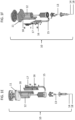
- proximal or proximal end is meant the end of the hollow needle that is away from or opposite the needle tip, e.g., the end of hollow needle 14 that is closer to z-actuator 12 and support base 11, as shown in FIGS. 1A-1F .
- distal or distal end is meant the end of the hollow needle that is at or close to the needle tip (e.g., needle tip 18 of FIGS. 1A-1F ).
- coring rate is meant the percentage of hollow needle actuations that result in cored tissue removal from the treatment area out of the total number of hollow needle actuations.
- the hollow needles of the invention are designed to maximize coring rate and minimize hollow needle actuations that do not result in cored tissue removal.
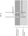
- a tissue portion detaches from the skin when the coring force exceeds the tissue resistance force.
- the tissue resistance force is determined by the connection of the tissue portion to its surrounding tissue. For example, when the hollow needle is fully inserted through the dermal layer of the skin, the tissue resistance force is determined by the connection between the tissue portion in the lumen of the needle and the subcutaneous fat layer.
- the coring rate is determined by, e.g., the coring force of the hollow needle, the friction between the lumen wall of the hollow needle and the tissue portion, and the tissue resistance force.
- the coring rate may also be affected by applying a pressure differential across the hollow needle. For example, a vacuum applied at the proximal end of the hollow needle may aspirate the cored tissue portion from the hollow needle, thereby, increasing the coring rate.
- coring force is meant the force applied by the hollow needle of the apparatus to the cored tissue portion as the needle is being withdrawn from the skin.
- the coring force is determined by, e.g., the friction between the lumen wall of the hollow needle and the cored tissue portion as the needle is being withdrawn from the skin and the position, geometry, and orientation of micro-features in the hollow needle.
- insertion force is meant the force generated by the hollow needle on the skin as it is inserted into the skin.
- the insertion force is initially determined by the amount of force required to penetrate the tissue. Once the tissue is penetrated, the insertion force is determine by the friction between the needle walls (inner and outer) and the surrounding tissue, as well as the force required to separate the tissue at the tip of the needle.
- This disclosure relates to hollow needles, needle assemblies, actuation units, apparatuses, kits, and methods for generating a cosmetic effect in the skin (e.g., eliminating tissue volume, tightening skin, and/or reducing skin laxity) by removing tissue portions from the skin.
- this approach facilitates skin remodeling by debulking the skin tissue and by triggering biological responses that contribute to tissue resurfacing and remodeling.
- the disclosure relates to hollow needles, as well as related needle assemblies, apparatuses, kits, and methods, capable of coring tissue portions by capturing and retaining the tissue portions inside the lumen of the hollow needle after insertion into and withdrawal from the skin. The cored tissue portions can be removed from the lumen of the hollow needle and discarded.
- the process can be repeated to generate multiple cored skin tissue portions, in particular over a desired area of skin and located at chosen sites of the body of a subject.
- the hollow needles, needle assemblies, actuation units, apparatuses, kits, and methods described herein provide increased effectiveness over currently available apparatuses and techniques while maintaining convenience, affordability, and accessibility to patients desiring tissue restoration.
- the apparatus of the disclosure includes at least one hollow needle having at least a first prong.
- an angle between a lateral side of the prong and a longitudinal axis of the hollow needle is at least about 20 degrees (e.g., the bevel angle ⁇ may be greater than about 20 degrees, such as greater than 20 degrees, 22 degrees, 24 degrees, 26 degrees, 28 degrees, 30 degrees, 32 degrees, 34 degrees, 36 degrees, 38 degrees, and 40 degrees, or at an angle of about 20 to about 40 degrees, between 20 to 40 degrees, 20 to 38 degrees, 20 to 36 degrees, 20 to 34 degrees, 20 to 32 degrees, 20 to 30 degrees, 20 to 28 degrees, 20 to 26 degrees, 20 to 24 degrees, 20 to 22 degrees, 22 to 40 degrees, 24 to 40 degrees, 26 to 40 degrees, 28 to 40 degrees, 30 to 40 degrees, 32 to 40 degrees, 34 to 40 degrees, 36 to 40 degrees, and 38 to 40 degrees).
- an angle between a lateral side of the prong and a longitudinal axis of the hollow needle is at least about 20 degrees (e.g.
- the tip of the prong of the hollow needle is an edge. In some embodiments, the tip of the prong of the hollow needle is a flat tip having at least two dimensions. In some embodiments, the prong of the hollow needle includes a tip micro-feature.
- the hollow needles of the disclosure are constructed to prevent frequent needle damage during use, such as needle tip curling and wear (e.g., becoming dull), needle heel degradation, and needle bending.
- the hollow needles of the disclosure are designed to maintain mechanical integrity and durability over a large number of actuation cycles (e.g., actuation cycles greater than 1,000, 2,000, 3,000, 4,000, 5,000, 6,000, 7,000, 8,000, 9,000, 1,0000, 11,000, 12,000, 13,000, 14,000, 15,000, or 20,000).
- these needles also effectively remove tissue portions from the skin with high coring rate.
- a hollow needle of the apparatus is inserted into the skin tissue, preferably to a pre-determined depth using a pre-determined force, such that the hollow needle removes a portion of the skin tissue by capturing the portion of the skin tissue in the lumen of the hollow needle.
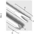
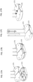
- distal end 20 of the hollow needle of the apparatus can be shaped to form one or more prongs 21.
- the hollow needle of the apparatus may have one prong at the distal end, two prongs, or more than two prongs (e.g., three, four, five, or six prongs).
- a hollow needle having one prong may be formed by grinding one side of the distal end of the hollow needle at an angle relative to the longitudinal axis of the hollow needle.
- a hollow needle having two prongs may be formed by grinding opposite sides of the distal end of the hollow needle at an angle relative to the longitudinal axis of the hollow needle.
- a bevel angle e.g., angle ⁇ as shown in FIG. 3
- An angle of "2 ⁇ ” refers to the angle between two lateral sides of the prong of the hollow needle, e.g., the angle between lateral side 31 and lateral side 33 of the hollow needle.
- a bevel angle ⁇ between a lateral side of a prong and a longitudinal axis of the hollow needle may be at least about 20 degrees (e.g., between about 20 and about 40 degrees (e.g., 20, 22, 24, 26, 28, 30, 32, 34, 36, 38, or 40 degrees)).
- an angle between a lateral side of a prong and a longitudinal axis of the hollow needle may be about 30 degrees.
- each prong may have the same bevel angle or different bevel angles.
- an angle between a lateral side of the first prong and a longitudinal axis of the hollow needle may be between about 20 and about 30 degrees (e.g., 20, 22, 24, 26, 28, or 30 degrees) and an angle between a lateral side of the second prong and a longitudinal axis of the hollow needle may be between about 30 and about 40 degrees (e.g., 30, 32, 34, 36, 38, or 30 degrees).
- the first prong may have a bevel angle ⁇ of 20 degrees and the second prong may have a bevel angle ⁇ of 30 degrees.
- a bevel angle ⁇ of at least about 20 degrees or more improves the mechanical integrity of the needle over several actuation cycles of insertion and withdrawal into skin tissue.
- Table 1 shows that a two-prong hollow needle having a 2 ⁇ bevel angle of 40 degrees (the bevel angle ⁇ of each prong is 20 degrees) reduces the occurrence of needle tip curling relative to a two-prong hollow needle having a 2 ⁇ bevel angle of 20 degrees (the bevel angle ⁇ of each prong is 10 degrees).
- a total of 5 two-prong hollow needles each having a bevel angle ⁇ of 10° and 5 two-prong hollow needles each having a bevel angle ⁇ of 20° were tested.
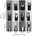
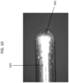
- FIG. 4 shows that increasing the needle bevel angle ⁇ of a prong also reduces the occurrence of needle heel degradation over a large number of actuation cycles.
- a hollow needle having a bevel angle ⁇ of 10 degrees displayed signs of needle heel degradation (indicated by dashed circles) before 2,000 actuation cycles, while a hollow needle having a bevel angle ⁇ of 20 degrees and a hollow needle having a bevel angle ⁇ of 30 degrees showed no apparent sign of needle heel degradation over 10,000 actuation cycles.
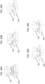
- the tip of a prong of a hollow needle may be of varying geometries.
- the tip of a prong may have a sharp point (e.g., sharp point 51 as shown in FIG. 5A ) or an edge (e.g., a one-dimensional edge) (e.g., edge 52 as shown in FIG. 5B ).
- each of the bevel angles of the prong may be at least about 20 degrees (e.g., from about 20 to about 40 degrees (e.g., about 30 degrees)).
- the prongs may have different bevel angles (e.g., a bevel angle ⁇ of about 20 degrees at the first prong and a bevel angle ⁇ of about 30 degrees at the second prong).
- the tip of a prong may be a flat tip (e.g., a flat tip having two dimensions) (e.g., flat tip 53 as shown in FIG. 5C ).
- a flat tip has a length and a width.
- the surface (length/width) of the flat tip of the prong may be at an angle relative to the longitudinal axis of the hollow needle.
- the surface of the flat tip may be perpendicular to the longitudinal axis of the hollow needle (e.g., at a 90 degree angle relative to the longitudinal axis of the hollow needle) or the surface of the flat tip may be at a non-90 degree angle relative to the longitudinal axis of the hollow needle (e.g., between about 3 to about 89 degrees, such as 3 to 89 degrees, e.g., 3, 6, 9, 12, 15, 18, 21, 24, 27, 30, 33, 36, 39, 42, 45, 48, 51, 54, 57, 60, 63, 66, 69, 72, 75, 78, 81, 84, 87, and 89 degrees).
- the surface of the flat tip may be level or may have different geometry, e.g., arc, groove, or non-level.
- each of the bevel angles of the prong may be between about 2 degrees to about 40 degrees (e.g., 2, 4, 6, 8, 10, 12, 14, 16, 18, 20, 22, 24, 26, 28, 30, 32, 34, 36, 38, or 40 degrees).
- the needle may have one or two prongs each with a two-dimensional flat tip in which one or both of the prongs have a bevel angle ⁇ of at least about 20 degrees (e.g., from about 20 to about 40 degrees (e.g., about 30 degrees)). Needles having a one-dimensional edge or a two-dimensional flat tip exhibit a reduced likelihood of needle tip curling.
- a hollow needle of the apparatus of the disclosure may be of any gauge, including gauges of from 18 to 30 (e.g., 18, 19, 20, 21, 22, 23, 24, 25, 26, 27, 28, 29, and 30 gauge).
- the gauges of a hollow needle may be from 22 to 25 (e.g., 22, 23, 24, and 25 gauge).
- a hollow needle of the apparatus may have an inner diameter of from about 0.14 mm to about 0.84 mm (e.g., 0.14, 0.15, 0.16, 0.17, 0.18, 0.19, 0.2, 0.21, 0.22, 0.23, 0.24, 0.25, 0.26, 0.27, 0.28, 0.29, 0.3, 0.31, 0.32, 0.33, 0.34, 0.35, 0.36, 0.37, 0.38, 0.39, 0.4, 0.41, 0.42, 0.43, 0.44, 0.45, 0.46, 0.47, 0.48, 0.49, 0.5, 0.51, 0.52, 0.53, 0.54, 0.55, 0.56, 0.57, 0.58, 0.59, 0.6, 0.61, 0.62, 0.63, 0.64, 0.65, 0.66, 0.67, 0.68, 0.69, 0.7, 0.71, 0.72, 0.73, 0.74, 0.75, 0.76, 0.77, 0.78, 0.79, 0.8, 0.81, 0.82, 0.83, and 0.84 mm).
- the inner diameter of a hollow needle refers to the diameter of the inner lumen of the hollow needle.
- the inner diameter of a hollow needle may be from about 0.24 mm to about 0.40 mm (e.g., 0.24, 0.25, 0.26, 0.27, 0.28, 0.29, 0.3, 0.31, 0.32, 0.33, 0.34, 0.35, 0.36, 0.37, 0.38, 0.39, and 0.4 mm).
- the diameter of a portion of skin tissue removed by a hollow needle of the apparatus e.g., a cored tissue portion
- a cored tissue portion generally corresponds to the inner diameter of the hollow needle.
- the outer and/or inner diameter of a hollow needle may vary across its lengths, such that the diameter of one region of the hollow needle may be different from the outer and/or inner diameter of another region of the same needle.
- the change in a diameter across the hollow needle may or may not be continuous.
- the hollow needle may or may not be entirely cylindrical.
- one or more hollow needles may be rectangular, serrated, scalloped, and/or irregular in one or more dimensions and along some or all of their lengths.
- the inner lumen diameter may vary along the length of a hollow needle.
- the disclosure also features a swaged hollow needle having a bevel angle ⁇ of at least 20 degrees (e.g., between about 20 and about 40 degrees (e.g., 20, 22, 24, 26, 28, 30, 32, 34, 36, 38, or 40 degrees)) and a variable inner lumen diameter over its length.
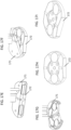
- FIGS. 5D and 5E show swaged hollow needle 54 having a smaller diameter near the distal end of the hollow needle (e.g., near the end of the needle that penetrates the skin tissue).
- FIG. 5D shows the outside of swaged hollow needle 54 and
- FIG. 5E shows a longitudinal cross-section of swaged hollow needle 54.
- the inner diameter may be wider at the proximal end of a hollow needle (e.g., away from the tip that penetrates the skin). This may facilitate the removal of the cored tissue portion from the hollow needle, may limit the need for clearing of the hollow needle, and may reduce the occurrence of needle clogging.
- a hollow needle of the apparatus may be of varying lengths and may have varying active lengths (e.g., the length of a hollow needle configured to penetrate the skin tissue). Active lengths may vary from about 0.5 mm to about 10 mm (e.g., 0.5, 0.6, 0.8, 1, 1.2, 1.4, 1.6, 1.8, 2, 2.2, 2.4, 2.6, 2.8, 3, 3.2, 3.4, 3.6, 3.8, 4, 4.2, 4.4, 4.6, 4.8, 5, 5.2, 5.4, 5.6, 5.8, 6, 6.2, 6.4, 6.6, 6.8, 7, 7.2, 7.4, 7.6, 7.8, 8, 8.2, 8.4, 8.6, 8.8, 9, 9.2, 9.4, 9.6, 9.8, and 10 mm) and may be selectable with manual or automatic controls (e.g., a scroll wheel or an actuation mechanism such as an electromagnetic actuator).
- a scroll wheel or an actuation mechanism such as an electromagnetic actuator
- Active lengths of a hollow needle may be adjusted and selected depending on the skin area needing treatment.
- hollow needle with active lengths from about 0.5 mm to about 2 mm (e.g., 0.5, 0.6, 0.8, 1, 1.2, 1.4, 1.6, 1.8, and 2 mm) may be used to treat thin skin, e.g., skin of an eyelid.
- the thickness of the epidermal and dermal layers of the skin of an eyelid may be from about 0.5 mm to about 1 mm (e.g., 0.5, 0.6, 0.8, and 1).
- Hollow needles with active lengths from about 5 mm to about 10 mm may be used to treat thick skin, e.g., skin of the back or scar tissue, which can be thicker than healthy skin tissue.
- the thickness of an epidermal layer of skin may be from about 0.05 to about 2 mm (e.g., 0.05 to 2, 0.05 to 1.95, 0.05 to 1.9, 0.05 to 1.85, 0.05 to 1.8, 0.05 to 1.75, 0.05 to 1.7, 0.05 to 1.65, 0.05 to 1.6, 0.05 to 1.55, 0.05 to 1.5, 0.05 to 1.45, 0.05 to 1.4, 0.05 to 1.35, 0.05 to 1.3, 0.05 to 1.25, 0.05 to 1.2, 0.05 to 1.15, 0.05 to 1.1, 0.05 to 1.05, 0.05 to 1, 0.05 to 0.95, 0.05 to 0.9, 0.05 to 0.85, 0.05 to 0.8, 0.05 to 0.75, 0.05 to 0.7, 0.05 to 0.65, 0.05 to 0.6, 0.05 to 0.55, 0.05 to 0.5, 0.05 to 0.45, 0.05 to 0.4, 0.05 to 0.35, 0.05 to 0.3, 0.05 to 0.25, 0.05 to 0.2, 0.05 to 0.15, 0.05 to 0.1
- the thickness of a dermal layer of skin may be from 2 to 8 mm (e.g., 2 to 8, 2 to 7.5, 2 to 7, 2 to 6.5, 2 to 6, 2 to 5.5, 2 to 5, 2 to 4.5, 2 to 4, 2 to 3.5, 2 to 3, 2 to 2.5, 2.5 to 8, 3 to 8, 3.5 to 8, 4 to 8, 4.5 to 8, 5 to 8, 5.5 to 8, 6 to 8, 6.5 to 8, 7 to 8, and 7.5 to 8 mm). Active lengths of a hollow needle may be adjusted and selected to penetrate the epidermal and/or the dermal layer of skin.
- Active lengths of a hollow needle may also be adjusted using one or more spacers (see FIG. 14 ), which are described in detail further herein.
- Hollow needle parameters may be selected based on the area of skin and the condition to be treated. For example, treatment of thin, lax skin on the cheeks may benefit from a hollow needle having an active length of about 2 mm and medium gauge (e.g., 25 gauge), while treatment of thick skin on the back or treatment of scar tissue may benefit from a hollow needle having an active length closer to 5 mm and a thicker gauge (e.g., 22 gauge).
- a hollow needle of the apparatus may be configured to extend to varying depths of the skin tissue.
- the depth of penetration of a hollow needle may be determined by the active length (e.g., from about 2 mm to about 5 mm) of the hollow needle.
- a hollow needle may be configured to extend (i) into the dermal layer, (ii) through the entire dermal layer to the junction of the dermal layer and the subcutaneous fat layer, and/or (iii) into the subcutaneous fat layer.
- a hollow needle of the apparatus may include one or more micro-features.
- a micro-feature is an element of the hollow needle that functions to help the hollow needle to capture or "grab" the tissue portion to be removed.
- a micro-feature may increase the coring rate of the hollow needle.
- a micro-feature may be located anywhere along the active length of the hollow needle. As shown in FIGS. 6A and 6B , micro-feature 61 or 62 is located near the tip of the hollow needle (e.g., a tip micro-feature). For example, a tip micro-feature may be located near the tip of prong 21 of the hollow needle.
- the distance between the tip of a prong of the hollow needle and the start of a micro-feature is from about 100 ⁇ m to about 5 mm (e.g., from 100 ⁇ m to 5 mm, 200 ⁇ m to 5 mm, 300 ⁇ m to 5 mm, 400 ⁇ m to 5 mm, 500 ⁇ m to 5 mm, 600 ⁇ m to 5 mm, 700 ⁇ m to 5 mm, 800 ⁇ m to 5 mm, 900 ⁇ m to 5 mm, 1 mm to 5 mm, 1.1 mm to 5 mm, 1.2 mm to 5 mm, 1.3 mm to 5 mm, 1.4 mm to 5 mm, 1.5 mm to 5 mm, 1.6 mm to 5 mm, 1.7 mm to 5 mm, 1.8 mm to 5 mm, 1.9 mm to 5 mm, 2 mm to 5 mm, 2.1 mm to 5 mm, 2.2 mm to 5 mm, 2.3 mm to 5 mm, 2.4
- Micro-features may be of varying geometries.
- a micro-feature may be a hole (see hole 61 of FIG. 6A ) (e.g., a circular hole or an oval-shaped hole) or a slit (see slit 62 of FIG. 6B ).
- a slit may be a rectangular-shaped slit, a square-shaped slit, a U-shaped slit, or a T-shaped slit.
- the shape and dimensions of the micro-feature can be optimized to maximize the ability of the hollow needle to capture a portion of the skin tissue, while minimizing the impact on the mechanical robustness and integrity of the hollow needle.
- a micro-feature may be a circular hole having a diameter of from about 10 ⁇ m to about 1 mm (e.g., from 10 ⁇ m to 1 mm, 10 ⁇ m to 900 ⁇ m, 10 ⁇ m to 880 ⁇ m, 10 ⁇ m to 860 ⁇ m, 10 ⁇ m to 840 ⁇ m, 10 ⁇ m to 820 ⁇ m, 10 ⁇ m to 800 ⁇ m, 10 ⁇ m to 780 ⁇ m, 10 ⁇ m to 760 ⁇ m, 10 ⁇ m to 740 ⁇ m, 10 ⁇ m to 720 ⁇ m, 10 ⁇ m to 700 ⁇ m, 10 ⁇ m to 680 ⁇ m, 10 ⁇ m to 660 ⁇ m, 10 ⁇ m to 640 ⁇ m, 10 ⁇ m to 620 ⁇ m, 10 ⁇ m to 600 ⁇ m, 10 ⁇ m to 580 ⁇ m, 10 ⁇ m to 560 ⁇ m, 10 ⁇ m to 540 ⁇ m, 10
- a micro-feature may be a slit having a length and a width (e.g., a rectangular-shaped slit, a square-shaped slit, a U-shaped slit, or a T-shaped slit), in which the length or width may be from about 10 ⁇ m to about 1 mm (e.g., from 10 ⁇ m to 1 mm, 10 ⁇ m to 900 ⁇ m, 10 ⁇ m to 880 ⁇ m, 10 ⁇ m to 860 ⁇ m, 10 ⁇ m to 840 ⁇ m, 10 ⁇ m to 820 ⁇ m, 10 ⁇ m to 800 ⁇ m, 10 ⁇ m to 780 ⁇ m, 10 ⁇ m to 760 ⁇ m, 10 ⁇ m to 740 ⁇ m, 10 ⁇ m to 720 ⁇ m, 10 ⁇ m to 700 ⁇ m, 10 ⁇ m to 680 ⁇ m, 10 ⁇ m to 660 ⁇ m, 10 ⁇ m to 640 ⁇ m,
- the micro-features may be designed and constructed to have a directional effect on the tissue portion captured inside the lumen of the hollow needle.
- the shape and orientation of the micro-feature may affect the coring force of the hollow needle.
- U-shaped slit 63 creates a hook near tip 21 of the hollow needle, which may help to retain the tissue portion inside the lumen of the hollow needle upon withdrawal of the needle from the skin.
- a micro-feature can intersect the inner wall of the hollow needle at a sharp edge, which can directionally affect the coring force of the hollow needle, as well as the resistance force applied by the cored tissue portion inside the lumen of the hollow needle.
- a micro-feature e.g., a hole or a slit
- a micro-feature drilled or micro-machined into a hollow needle may intersect the inner wall of the hollow needle at a perpendicular angle or at a non-perpendicular angle (e.g., an angle of from about 5 degrees to less than about 90 degrees, such as 5 to 85 degrees, 5 to 80 degrees, 5 to 75 degrees, 5 to 70 degrees, 5 to 65 degrees, 5 to 60 degrees, 5 to 55 degrees, 5 to 50 degrees, 5 to 45 degrees, 5 to 40 degrees, 5 to 35 degrees, 5 to 30 degrees, 5 to 25 degrees, 5 to 20 degrees, 5 to 15 degrees, 5 to 10 degrees, 10 to 85 degrees, 15 to 85 degrees, 20 to 85 degrees, 25 to 85 degrees, 30 to 85 degrees, 35 to 85 degrees, 40 to 85 degrees, 45 to 85 degrees, 50 to 85 degrees, 55 to 85 degrees, 60 to 85 degrees, 65 to 85 degrees, 70 to 85 degrees, 75 to 85 degrees, and 80 to 85 degrees).
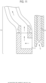
- FIG. 7 shows hollow needle 14 containing tip micro-feature 71 that intersects inner wall 72 of hollow needle at a non-perpendicular angle ⁇ and creates sharp edge 73.
- tissue portion 74 enters the hollow needle from needle tip 18, tissue portion 74 is traveling in the direction of lower resistance.
- micro-feature 71 helps to retain tissue portion 74 inside the lumen of hollow needle 14 and prevents tissue portion 74 from being released from hollow needle 14.
- One or more micro-features may be micro-machined into the hollow needle through available processes and techniques, such as laser drilling and wire electrostatic discharge machining (EDM).
- EDM laser drilling and wire electrostatic discharge machining
- a hollow needle of the apparatus may be coated with a material (e.g., a hard material) that improves or maintains the mechanical integrity, durability, and reliability of the hollow needle.
- the coating material may help to prevent damage, abrasion, and wear and tear of the needle tip and heel during repeated insertions into and withdrawals from skin tissue.
- materials e.g., a hard material
- Examples of materials (e.g., a hard material) that may be used to coat a hollow needle of the apparatus include, but are not limited to, TiN, TiCN, TiAlN, ZrN, and diamond-like carbon (DLC).
- the hard material may be applied as a coating to the outside surface of a hollow needle, the inner surface (e.g., the surface of the inner lumen) of a hollow needle, or both surfaces.
- FIG. 8A-8C show that a hollow needle coated with DLC exhibited a reduction in needle heel and tip degradation over 10,000 actuation cycles of insertions and withdrawals into pig skin, while a non-coated hollow needle showed needle heel and tip degradation (indicated by dashed circles) over 10,000 actuation cycles of insertions and withdrawals into pig skin ( FIG. 8D ).
- the lumen surface of a hollow needle may affect the coring force, coring rate, and insertion force of the hollow needle.
- the friction between the lumen surface and a cored tissue portion may determine the coring force, coring rate, and insertion force.
- the hollow needles described herein are designed to maximize coring rate and minimize hollow needle insertions that do not result in cored tissue removal.
- a tissue portion detaches from the skin when the coring force (e.g., the force applied by the hollow needle of the apparatus to the cored tissue portion as the needle is being withdrawn from the skin) exceeds the tissue resistance force, which is determined by the connection of the tissue portion to its surrounding tissue.
- the tissue resistance force is determined by the connection between the tissue portion in the lumen of the needle and the subcutaneous fat layer. Accordingly, when the coring force exceeds the tissue resistance force, the cored tissue portion is captured in the lumen of the hollow needle and removed from the skin ( FIG. 9 ).
- a rough lumen surface increases the friction between the cored tissue portion and the lumen surface, which may result in increased insertion force, increased coring force, and increased coring rate. Lubrication of the lumen surface reduces the friction between the cored tissue portion and the lumen surface, which may result in decreased insertion force, decreased coring force, and decreased coring rate.
- An overly rough and uneven lumen surface may lead to high occurrence of needle degradation (e.g., needle heel and tip degradations), may cause difficulty in removing cored tissue portions from the lumen, and/or may cause needle clogging.
- the degree of roughness of the lumen surface may be optimized to increase the coring force and coring rate without compromising the durability of the needle, the insertion force, the ability to remove tissue from the needle lumen, and the resistance of the needle to degradation (e.g., needle heel and tip degradation).
- hollow needles and methods may have a coring rate of at least about 5% (e.g., from about 5% to about 100%, such as 5% to 100%, 5% to 95%, 5% to 90%, 5% to 85%, 5% to 80%, 5% to 75%, 5% to 70%, 5% to 65%, 5% to 60%, 5% to 55%, 5% to 50%, 5% to 45%, 5% to 40%, 5% to 35%, 5% to 30%, 5% to 25%, 5% to 20%, 5% to 15%, 5% to 10%, 10% to 95%, 15% to 95%, 20% to 95%, 25% to 95%, 30% to 95%, 35% to 95%, 40% to 95%, 45% to 95%, 50% to 95%, 55% to 95%, 60% to 95%, 65% to 95%, 70% to 95%, 75% to 95%, 80% to 95%, 85% to 95%, and 90% to 95%).
- 5% to 35% 5% to 30%, 5% to 25%, 5% to 20%, 5%
- hollow needles and methods may have a coring force of about 3 N to about 10 N (e.g., 3, 3.5, 4, 4.5, 5, 5.5, 6, 6.5, 7, 7.5, 8, 8.5, 9, 9.5, and 10 N).
- a two-prong hollow needle having a bevel angle ⁇ of 20 degrees may have a coring force of about 3 N to about 10 N (e.g., 3, 3.5, 4, 4.5, 5, 5.5, 6, 6.5, 7, 7.5, 8, 8.5, 9, 9.5, and 10 N).
- a coating material and/or a lubricant may affect the degree of roughness of the lumen surface, and thus the friction between the lumen surface and a cored tissue portion.
- the lumen surface of a hollow needle may be polished by running a lubricant or a polishing media though the hollow needle to reduce the roughness of the lumen surface.
- lubricants include, but are not limited to, salt-based lubricants (e.g., buffered saline solutions (e.g., PBS)), sugar-based lubricants (e.g., sucrose and glucose solutions), and surfactant-based lubricants (e.g., solutions containing Tween20).
- the degree of roughness of the lumen surface of the hollow needle may also be affected by the manufacturing process used to make the hollow needle.
- Table 2 below shows lumen surface roughness measured in Ra (arithmetic average of roughness profile) and Rz (mean roughness depth) of hollow needles made using single plug, double plug, and sunk manufacturing processes.
- the lumen surface of hollow needles made using double plug process is smoother (lower Ra and Rz values) than the lumen surface of hollow needles made using single plug process.
- a hollow needle of the apparatus may be made using available manufacturing techniques and processes. For example, manufacturing of a hollow needle starts with drawing the needle hypodermic tube, followed by forming the needle tip.
- the needle hypodermic tube may be drawn using manufacturing processes, e.g., single plug, double plug, and sunk.
- the needle tip may be formed by grinding.
- a hollow needle having one prong may be formed by grinding one side of the distal end of the hollow needle at an angle relative to the longitudinal axis of the hollow needle.
- a hollow needle having two prongs may be formed by grinding opposite sides of the distal end of the hollow needle at an angle relative to the longitudinal axis of the hollow needle.
- the grinding process may be performed at a low temperature to prevent or reduce annealing of the needle material and to prevent the needle material from undergoing phase transitions at high temperatures (e.g., at alloy transition temperature, which is defined by the alloy stoichiometry). Annealed material may become ductile and more prone to bending, which may reduce the durability and mechanical integrity of the hollow needle. Maintaining a low temperature (e.g., a temperature lower than the alloy transition temperature) during the grinding process may be achieved by, e.g., reducing the grinding speed and/or grinding rate and using a cooling fluid (e.g., periodically submerging the needle material and/or the grinding machinery in a cooling fluid). In some embodiments, the cooling fluid used may be at room temperature. Other non-grinding techniques and processes may also be used to manufacture the hollow needle(s) of the apparatus, e.g., electrical discharge machining.
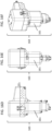
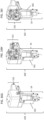
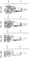
- FIGS. 1A-1F are schematic illustrations of an exemplary needle assembly 10 of the invention including support base 11, z-actuator (e.g., a voice coil) 12, tissue removal tool (e.g., a piston) 13, hollow needle 14, aspiration tube 15, trap 16, pressure generating source (e.g., a vacuum pump) 17, and scaffold 18.
- z-actuator e.g., a voice coil
- tissue removal tool e.g., a piston
- hollow needle 14 aspiration tube
- trap 16 pressure generating source e.g., a vacuum pump
- scaffold 18 e.g., a vacuum pump
- a needle assembly of the apparatus e.g., needle assembly 10 shown in FIGS. 1A-1F , 15B , and 16G-16U
- a needle assembly of the apparatus is detachably attached to other components of the apparatus (e.g., to an actuation unit of the apparatus) for easy and quick connection and disconnection.
- the needle assembly (e.g., needle assembly 10 ) is detachably attached to an actuation unit of the apparatus (e.g., actuation unit 151 shown in FIGS. 15A, 15B , 16B , and 16G-16U ) using a locking or connecting mechanism (described further herein; see FIGS, 17A-17I , 18A-18C , 19A-19C , 20A-20E , 21A-21D , and 22A-22D ).
- the entire needle assembly and/or components of the needle assembly is detached from other components of the apparatus (e.g., detached from the actuation unit) to be replaced or sterilized after use.
- Needle assembly 10 may include additional components, such as tubing and/or cables to couple various components and device control electronics, a power supply (e.g., an alternator and/or battery component), and/or a user interface.
- the components of the needle assembly may be detachably engaged for easy and quick connection and disconnection.
- the components of the needle assembly may be readily cleaned, sterilized (e.g., by steam sterilization or other known methods), and/or replaced.
- the components of the needle assembly may be provided to an operator (e.g., a doctor or surgeon) in sterile condition prior to use on a patient and many, if not all, of the components can be re-sterilized or replaced with sterile components prior to a subsequent use.
- components of the needle assembly and/or the entire needle assembly may be readily removable from the apparatus for sterilization or replacement after use of the apparatus.
- Z-actuator 12 is configured to couple with hollow needle 14 in needle assembly 10.
- Z-actuator (e.g., a voice coil) 12 may have a locking mechanism to secure the hollow needle 14 in place during operation.
- z-actuator 12 and hollow needle 14 may be locked by establishing a magnetic connection between the two.
- z-actuator 12 and hollow needle 14 may be locked by establishing a mechanical connection between the two using, e.g., quick-connect clasps.
- the z-actuator-hollow needle locking mechanism may be detachably engaged for easy and quick connection and disconnection.
- the z-actuator-hollow needle locking mechanism may include one or more of adhesive, magnetic, electrical, and/or mechanical components (e.g., one or more gaskets, o-rings, septa, springs, clasps, and other engagement members).
- the z-actuator may include a groove or depression for placement of an o-ring (e.g., a viton o-ring, a nitrile rubber o-ring, and a thermoplastic polyurethane o-ring) that will allow for a seal to form between z-actuator 12 and hollow needle 14.
- the portion of hollow needle 14 engineered to engage with z-actuator 12 may include a corresponding groove or depression.
- a locking mechanism may involve mated pieces made of molded plastic.
- hollow needle 14 may form a seal by sliding partway into z-actuator 12.
- Z-actuator 12 and hollow needle 14 may also include interlocking ridges (e.g., made of plastic, rubber, or other material) to enhance or form a seal between the components.
- Z-actuator 12 may also feature a mechanism to activate detachment of hollow needle 14 from z-actuator 12. This mechanism may include one or more of a button, key, switch, toggle, spin-wheel, touch screen, and/or sliding lock.
- the detachment mechanism may be a quick-release mechanism.
- one component e.g., z-actuator 12
- one component includes a depressible portion that engages a seal when the other component (e.g., hollow needle 14 ) is slid into the other. Depression of the portion may be disengaged by activation of a sliding lock, eliminating the seal between the components to allow their separation and, e.g., removal and replacement of hollow needle 14.
- Needle assembly 10 may also include a power supply or be detachably attached to a power supply.
- needle assembly 10 may have a holder for batteries that power operation of the apparatus or may be configured to receive an element including batteries. The holder may be configured to charge the batteries (e.g., when depleted) with a paired charging station, without requiring removal of the batteries, or the batteries may be removed from the apparatus for replacement or charging.
- needle assembly 10 may include electronics and components (e.g., a power cord) that allow it to be powered from an external power supply, such as a direct or alternating current supply or a generator.
- Cored tissue portion(s) may require removal from the lumen of a hollow needle of the apparatus after the needle containing the cored tissue portion inside its lumen is withdrawn from the skin, e.g., in order to continue the skin treatment procedure.
- the cored tissue portion may be removed from the needle lumen after each actuation cycle or after multiple actuation cycles.
- a tissue removal tool e.g., a piston
- proximal end e.g., the end opposite the needle tip
- the cored tissue portion may be removed through the distal end of the hollow needle (e.g., at the needle tip) using an aspiration tube coupled to a pressure generating source (e.g., a vacuum).
- the cored tissue portion may also be removed through the proximal end of the hollow needle by applying a differential pressure (e.g., a vacuum) or out of the distal end of the needle using compressed air or a pressurized fluid to push the cored tissue portion out of the distal end.
- a tissue removal tool may be used to push the cored tissue portion out of the lumen of a hollow needle.
- a tissue removal tool may be a piston or a pin that can fit inside the lumen of the hollow needle (e.g., without creating a vacuum inside the lumen (e.g., the gap between the tissue removal tool and the wall of the lumen of the hollow needle is large enough to allow the passage of air)).
- the tissue removal tool is a piston.
- a tissue removal tool (e.g., a piston) does not disrupt the structural integrity of the cored tissue portion.
- a tissue removal tool e.g., a piston
- a piston may be of varying geometry.
- the cross-section of the piston may be, e.g., round, oval, rectangular, or square. In a preferred embodiment, the cross-section of the piston is round.
- the geometry of the piston matches the shape of the lumen of the hollow needle such that the piston fits well inside the lumen and is able to freely slide along the longitudinal axis of the hollow needle, for example, without creating a vacuum.
- the piston may have a diameter that is less than the inner diameter of the hollow needle (e.g., a diameter that is 0.01% to 10% less (e.g., 0.01%, 0.05%, 0.1%, 0.15%, 0.2%, 0.25%, 0.3%, 0.35%, 0.4%, 0.45%, 0.5%, 1%, 1.5%, 2%, 2.5%, 3%, 3.5%, 4%, 4.5%, 5%, 5.5%, 6%, 6.5%, 7%, 7.5%, 8%, 8.5%, 9%, 9.5%, or 10% less).
- the end of the piston which touches the cored tissue portion as the piston pushes the cored tissue portion out of or towards the distal end of the needle, may be round or flat. For example, as shown in FIG.
- end 101 of piston 102 is round.
- a rounded piston end may prevent the attachment of the cored tissue portion to the piston during tissue removal.
- the piston may be polished to minimize friction and abrasion between the piston and the inner wall of the hollow needle, thus reducing wear and tear of the inner wall.
- the piston may stay at a constant position.
- the hollow needle is moved up and down to engage the stationary piston.
- the piston may be inserted and withdrawn from the lumen of a hollow needle.
- tissue removal tool e.g., a piston
- Tissue removal tool 13 is constructed to fit inside the lumen of the needle. Hollow needle 14 continues to move upward, which allows tissue removal tool (e.g., a piston) 13 to extend further into the lumen and all the way to needle tip 18, thereby pushing the cored tissue portion towards or out of needle tip 18.
- tissue removal tool e.g., a piston
- tissue removal tool 13 moves down towards to the end of hollow needle 14 and enters the needle lumen through the proximal end of the needle.
- tissue removal tool e.g., a piston
- hollow needle 14 containing the cored tissue portion stays stationary while tissue removal tool (e.g., a piston) 13 moves downward to needle tip 18, thereby pushing the cored tissue portion towards or out from needle tip 18.
- the length of tissue removal tool (e.g., a piston) 13 may be adjusted to allow the cored tissue portion to be pushed towards or out of needle tip 18 while the needle is in its uppermost position and not penetrating into the skin.
- One or more actuators may be coupled to a needle assembly (e.g., needle assembly 10 shown in FIGS. 1A-1F , 15B , and 16G-16U ) to move the hollow needle (e.g., hollow needle 14 ) away from the skin surface before the cored tissue portion is pushed out by the tissue removal tool (e.g., a piston; e.g., see tissue removal tool 13 shown in FIGS. 1A-1F ) such that the cored tissue portion does not drop onto the skin surface once it is pushed out.
- the tissue removal tool e.g., a piston; e.g., see tissue removal tool 13 shown in FIGS. 1A-1F
- An aspiration tube (e.g., aspiration tube 15 shown in FIGS. 1A-1F ) may be used in combination with a tissue removal tool (e.g., a piston) to remove the cored tissue portion from the needle tip.
- the aspiration tube may stay at a constant position.
- tissue removal tool e.g., a piston
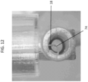
- aspiration tube 15 located in proximity to needle tip 18 may be used to remove cored tissue portion 74 through a suction force.
- the opening of aspiration tube 111 may be in proximity to needle tip 18 when the needle is in its uppermost position.
- pressure generating source (e.g., a vacuum pump) 17 may be connected to aspiration tube 15 to provide the suction force.
- trap 16 may be installed between aspiration tube 15 and pressure generating source (e.g., a vacuum pump) 17 to collect the cored tissue portions for disposal, subsequent use (e.g., tissue graft or growth), or biochemical analysis and to prevent the cored tissue portion from entering pressure generating source (e.g., a vacuum pump) 17.
- FIG. 12 further shows cored tissue portion 74 at needle tip 18.
- a cored tissue portion inside the lumen of a hollow needle may be collected at the proximal or distal end of the needle by applying a differential pressure across the needle.
- the needle may move to a dock station or a separate unit, which may contain a pressure generating source (e.g., a vacuum pump) that provides suction and/or vacuum at the proximal end of the needle. Suction and/or vacuum may be applied at the proximal end of the hollow needle to pull the cored tissue portion out of the needle from its proximal end.
- a pressure generating source e.g., a vacuum pump
- a trap may be installed at the proximal end of the needle and between the needle and the pressure generating source (e.g., a vacuum pump) to collect the cored tissue portions for disposal, subsequent use (e.g., tissue graft or growth), or biochemical analysis and to prevent the cored tissue portions from entering the pressure generating source (e.g., a vacuum pump).
- a differential pressure may be applied to a hollow needle (e.g., a swaged hollow needle having a variable inner lumen diameter over its length and a bevel angle ⁇ of at least 20 degrees (e.g., swaged hollow needle 54 )). Tissue removal may be facilitated by increasing the inner lumen diameter in the direction of the tissue removal.
- An increased inner lumen diameter in part of a hollow needle may reduce the friction between the cored tissue portion and the wall of the needle lumen.
- suction and/or vacuum may be applied at the proximal end of a hollow needle (e.g., a swaged hollow needle having a variable inner lumen diameter over its length and a bevel angle ⁇ of at least 20 degrees (e.g., swaged hollow needle 54 )) to pull the cored tissue portion out from the proximal end.
- a burst of high pressure may be applied at the proximal end of a hollow needle to pull the cored tissue portion out of the needle from its proximal end.
- high pressure port 131 may be coupled to tissue recovery port 132, which collects the cored tissue portions.
- a pressure generating source e.g., a vacuum pump
- suction and/or vacuum may be applied at the distal end of the hollow needle to pull the cored tissue portion out of the needle from its distal end.
- tissue removal tool e.g., tissue removal tool (e.g., a piston) 13
- tissue removal tool e.g., a piston
- suction and/or vacuum may be applied at the distal end of the hollow needle to remove the cored tissue.
- the minimal air flow rate in the aspiration line of a pressure generating source is from about 1 cubic feet per minute (CFM) to about 6 CFM (e.g., 1, 2, 3, 4, 5, and 6 CFM (e.g., 3 CFM)).
- 1 mmHg 0,133322 kPa
- a cored tissue portion inside the lumen of a hollow needle may be pushed out of the proximal end of the needle by the insertion of one or more new tissue portions during the subsequent actuation cycles.
- the inner wall of the hollow needle may be lubricated by, e.g., a sterile saline solution, to prevent clogging of the needle as multiple tissue portions are inserted into the needle.
- a trap may be attached at the proximal end of the needle to collect the cored tissue portions as they are being pushed out of the needle for disposal, subsequent use (e.g., tissue graft or growth), or biochemical analysis.
- a cored tissue portion inside the lumen of the needle may be removed from the needle by applying compressed air or a pressurized fluid (e.g., a sterile saline solution) through the needle.
- Compressed air or pressurized fluid may be applied through the proximal end to push the cored tissue portion out from the distal end of the needle.
- a cored tissue portion inside the lumen of the needle may also be removed from the needle using a heating element coupled to the needle.
- a heating element coupled to the needle may be actuated which causes the needle to heat up to facilitate separation of the cored tissue portion from the surrounding skin.
- the cored tissue portion may be dried or desiccated prior to being removed from the lumen of the hollow needle.
- a vacuum source may then be applied to remove the heated cored tissue portion.
- the apparatus may further include or be otherwise coupled to a pressure generating source.
- a pressure generating source may be applied to remove and/or collect cored tissue portions from the lumen of a hollow needle to prevent needle clogging during operation.
- suction and/or vacuum may be applied via a hollow needle of the apparatus.
- a hollow needle and a pressure generating source e.g., a vacuum pump
- a pressure generating source may be configured to remove and/or collect cored tissue portions from the lumen of the hollow needle by providing suction and/or vacuum after penetration of the hollow needle into the skin but before removal of the hollow needle from the skin.
- vacuum may be applied to draw the tissue portion in the lumen of the hollow needle from a treated skin area through the proximal end of the hollow needle and through tubing coupling the hollow needle to the pressure generating source (e.g., a vacuum pump).
- a trap may be installed between the proximal end of the hollow needle and the pressure generating source (e.g., a vacuum pump) to prevent the tissue portion from entering the pressure generating source (e.g., a vacuum pump).
- the pressure generating source e.g., a vacuum pump
- the pressure generating source may also be activated after the hollow needle containing the tissue portion in the lumen is removed from the skin.
- the pressure generating source may be integrated with a separate aspiration tube.
- tissue removal tool e.g., a piston
- Aspiration tube 15 integrated with pressure generating source (e.g., a vacuum pump) 17 may be placed proximal to needle tip 18 to provide suction and/or vacuum after the cored tissue portion is pushed to needle tip 18.
- Trap 16 may be installed between aspiration tube 15 and pressure generating source (e.g., a vacuum pump) 17 to prevent the cored tissue portion from entering pressure generating source (e.g., vacuum pump) 17.
- the pressure generating source may be a low pressure generating source.
- the pressure generating source may be capable of providing vacuum and/or suction.
- Vacuum sources may include one or more rotary pumps, momentum transfer pumps, diffusion pumps, scroll pumps, and/or diaphragm pumps.
- a low pressure generating source may include a house or central vacuum system.
- a suction source may include a wall or portable suction device.
- a vacuum source provides an absolute pressure less than about 6.3 kPa (e.g., from about 0.1 kPa to about 6 kPa, such as from 0.1 kPa to 6 kPa, 0.1 kPa to 5 kPa, 0.1 kPa to 4 kPa, 0.1 kPa to 3 kPa, 0.1 kPa to 2 kPa, 0.1 kPa to 1 kPa, 0.5 kPa to 6 kPa, 0.5 kPa to 5 kPa, 0.5 kPa to 4 kPa, 0.5 kPa to 3 kPa, 0.5 kPa to 2 kPa, 0.5 kPa to 1 kPa, 1 kPa to 6 kPa, 1 kPa to 5 kPa, 1 kPa to 4 kPa, 1 kPa to 3 kPa, 1 kPa to 2
- An apparatus of the disclosure may include one or more spacers that function to control the depth of penetration of a hollow needle.
- Skin thickness varies significantly between body sites and in some cases, between subjects. Tissue penetration depth is important to ensure coring tissue portions of the appropriate size and to avoid injury to tissue layers beyond the subcutaneous fat layer (e.g., muscle layer).
- One or more spacers may be attached to the apparatus, e.g., between the cover of the apparatus and the skin (see FIGS. 14A, 14B , and 16A-16C ).
- a spacer is configured to control the depth of insertion of a hollow needle and allows adjustments of the extension and penetration of the hollow needle into the skin.
- FIGS. 14A and 14B show two spacers 141 and 142 that allow different insertion depths of hollow needle 14.
- "zero" spacer 141 ( FIG. 14A ) attached to the distal end of cover 161 of the apparatus allows a 10 mm insertion depth of hollow needle 14.
- This type of spacer may be added to the distal end of the cover of the apparatus of the disclosure for coring thick skin tissues, which requires a deep penetration of the hollow needle.
- "2 mm" spacer 142 ( FIG. 14B ) attached to the distal end of cover 161 of the apparatus allows an 8 mm insertion depth of hollow needle 14.
- Thick spacers (e.g., spacer 142 of FIG. 14B ) may be configured to decrease the depth of penetration of the hollow needle and may be used for coring thin skin tissues, e.g., skin tissues of the face.
- Thin spacers (e.g., spacer 141 of FIG. 14A ) may be configured to increase the depth of penetration of the hollow needle and may be used for coring thick skin tissues.
- a spacer may have a thickness of from about 0.01 mm to about 10 mm (e.g., from 0.1 mm to 10 mm, 0.1 mm to 9.5 mm, 0.1 mm to 9 mm, 0.1 mm to 8.5 mm, 0.1 mm to 8 mm, 0.1 mm to 7.5 mm, 0.1 mm to 7 mm, 0.1 mm to 6.5 mm, 0.1 mm to 6 mm, 0.1 mm to 5.5 mm, 0.1 mm to 5 mm, 0.1 mm to 4.5 mm, 0.1 mm to 4 mm, 0.1 mm to 3.5 mm, 0.1 mm to 3 mm, 0.1 mm to 2.5 mm, 0.1 mm to 2 mm,
- the apparatus may further include actuation mechanisms to drive a hollow needle into or across the skin.
- an actuation unit of the apparatus of the disclosure may include x-, y-, and z-actuators.
- an actuation unit of the apparatus of the disclosure e.g., actuation unit 151 shown in FIGS. 15A and 15B
- a z-actuator e.g., a voice coil
- a z-actuator e.g., a voice coil
- the "x,” “y,” and/or “z” actuators may drive a hollow needle into and/or across a large area of skin surface in a relatively short amount of time compared to manual deployment of a hollow needle.
- the "x,” “y,” and/or “z” actuators may drive a hollow needle into and/or across a small area of skin surface (e.g., a small area on the face (e.g., the area between the nose and the upperlip)).
- the "x,” “y,” and/or “z” actuators may drive a hollow needle into and/or across multiple large and/or small areas of skin surface.
- a "z” actuator may drive penetration into the skin by a hollow needle and/or retraction of the hollow needle after insertion.
- a z-actuator e.g., a voice coil
- the apparatus may include a feature or setting that has the ability to control or change the depth of penetration of the hollow needle into the skin. For example, a scroll wheel on a user interface of the base unit may adjust the allowed depth of penetration by the hollow needle by physically retracting the hollow needle and/or providing an electrical signal to a z-actuator.
- digital controls on the user interface of the base unit may control the depth and/or timing of penetration into and retraction out of the skin by the hollow needle.
- an operator may program a computer component of the base unit to require a certain displacement of the hollow needle into the skin based upon the area being treated.
- the z-actuator may be programmed or otherwise set to displace the hollow needle up to about, e.g., 10 mm into thick skin (e.g., on a patient's back or into scar tissue), or about, e.g., 1 mm into thin skin (e.g., on a patient's cheeks), for instance.
- the z-actuator may be programmed or otherwise set to displace the hollow needle to extend (i) into the dermal layer, (ii) through the entire dermal layer to the junction of the dermal layer and the subcutaneous fat layer, or (iii) into the subcutaneous fat layer.
- the z-actuator may also be capable of operating at a high speed to minimize treatment time and deflection of the skin during the penetration of the hollow needle.
- one actuation cycle in the z-direction takes from about 5 milliseconds to about 50 milliseconds (e.g., 5, 10, 15, 20, 25, 30, 35, 40, 45, and 50 milliseconds).
- the z-actuator takes about 20 to about 35 milliseconds (e.g., 20, 21, 22, 23, 24, 25, 26, 27, 28, 29, 30, 31, 32, 33, 34, and 35 milliseconds) to travel about 20 mm to about 30 mm (e.g., 20, 21, 22, 23, 24, 25, 26, 27, 28, 29, and 30 mm) downward into the skin tissue.
- the z-actuator takes about 25 milliseconds to about 30 milliseconds (e.g., 25, 26, 27, 28, 29, and 30 milliseconds) to travel about 23 mm downward into the skin tissue. In some embodiments, the z-actuator takes about 25 to about 35 milliseconds (e.g., 25, 26, 27, 28, 29, 30, 31, 32, 33, 34, and 35 milliseconds (e.g., 30 milliseconds)) to travel about 20 mm to about 30 mm (e.g., 20, 21, 22, 23, 24, 25, 26, 27, 28, 29, and 30 mm (e.g., 23 mm)) upward from a penetration depth of about 20 mm to about 30 mm (e.g., 20, 21, 22, 23, 24, 25, 26, 27, 28, 29, and 30 mm (e.g., 23 mm)) into the skin tissue. In some embodiments, the z-actuator takes about 30 milliseconds to travel about 23 mm upward from the penetrated skin tissue.
- the z-actuator takes about 30 milliseconds to travel about 23
- the z-actuator may further be capable of operating with relatively high insertion force.
- a force of about 0.5 N to about 20 N e.g., 0.5 N to 0. 75 N, 0.5 N to 1 N, 0.5 N to 1.25 N, 0.5 N to 1.5 N, 0.5 N to 2 N, 0.5 N to 5 N, 0.5 N to 10 N, 0.5 N to 12 N, 0.5 N to 15 N, 0.5 N to 20 N, 0.75 N to 1 N, 0.75 N to 1.25 N, 0.75 N to 1.5 N, 0.75 N to 2 N, 0.75 N to 5 N, 0.75 N to 10 N, 0.75 N to 12 N, 0.75 N to 15 N, 0.75 N to 20 N, 1 N to 1.25 N, 1 N to 1.5 N, 1 N to 2 N, 1 N to 5 N, 1 N to 10 N, 1 N to 12 N, 1 N to 15 N, 1 N to 20 N, 1.25 N to 1.5 N, 1.25 N to 2 N, 1.25 N to 5 N, 1 N to 10 N, 1 N to
- a force of about 10 N to 20 N (e.g., 15 N) per hollow needle can be applied to ensure insertion of the hollow needle into the skin.
- the insertion force may be inversely correlated with needle gauge.
- a 24 gauge needle may be operated with an insertion force of 12 N, while a 20 gauge needle may be operated with a higher insertion force.
- the z-actuator may also be capable of maintaining the apparatus at a low temperature (e.g., less than about 43 °C, such as less than about 43, 42, 41, 40, 39, 38, 37, 36, or 35 °C) to avoid patient and user discomfort and/or to avoid damage to the skin tissue (e.g., collagen in the skin tissue is sensitive to high temperatures).
- Actuator types having these characteristics include voice coil (VC) actuators, pneumatic actuators, electromagnetic actuators, motors with cams, motors with lead screws (e.g., stepper motors), and piezoelectric actuators.
- VC voice coil
- the z-actuator is a VC actuator.
- the apparatus may include an "x" and/or "y” actuator for translating a hollow needle across the skin.
- the x/y-actuator may be used to establish the skin treatment coverage.
- the x/y-actuator may be characterized by a small displacement range (e.g., less than about 10 mm (e.g., 10, 9, 8, 7, 6, 5, 4, 3, 2, and 1 mm)).
- the x/y-actuator may be characterized by a relatively large displacement range (e.g., up to about 30 mm).
- the x/y-actuator may operate with high positional accuracy.
- x/y-actuator may position the hollow needle to penetrate the skin within a 30 ⁇ m radius (e.g., within 30, 25, 20, 15, 10, or 5 ⁇ m) of a selected position.
- the x/y-actuator may operate with high position accuracy that allows continuous treatment across a treatment area.
- a treatment area may be a skin area that contains multiple treatment sites, e.g., a 3 cm by 3 cm treatment area containing nine 1 cm 2 treatment sites.
- the x/y-actuator may facilitate movement of the hollow needle(s) of the apparatus from one treatment site to the adjacent treatment site within the treatment area.
- the x/y-actuator may also facilitate movement of the hollow needle(s) of the apparatus within each treatment site.
- the x/y-actuator may operate with high position accuracy that avoid gaps between adjacent treatment sites in the treatment area and/or avoid overlaps between adjacent treatment sites in the treatment area.
- the x/y-actuator may also operate at a relatively high speed to minimize treatment time.
- one actuation cycle in the x- and/or y-direction takes from about 50 milliseconds to about 250 milliseconds (e.g., 50, 75, 100, 125, 150, 175, 200, 225, and 250 milliseconds).
- one actuation cycle in the x- and/or y-direction takes about 120 milliseconds to about 160 milliseconds (e.g., 120, 125, 130, 135, 140, 145, 150, 155, and 160 milliseconds (e.g., about 140 milliseconds)).
- one actuation cycle in the x- and/or y-direction takes about 120 milliseconds to about 160 milliseconds (e.g., 120, 125, 130, 135, 140, 145, 150, 155, and 160 milliseconds (e.g., about 140 milliseconds)) to travel about 0.6 mm to about 1 mm (e.g., 0.6, 0.65, 0.7, 0.75, 0.8, 0.85, 0.9, 0.95, and 1 mm). In some embodiments, one actuation cycle in the x- and/or y-direction takes about 140 milliseconds to travel about 0.833 mm.
- the x/y-actuator may be capable of operating with a force of about 0.5 N to about 20 N (e.g., 0.5 N to 0. 75 N, 0.5 N to 1 N, 0.5 N to 1.25 N, 0.5 N to 1.5 N, 0.5 N to 2 N, 0.5 N to 5 N, 0.5 N to 10 N, 0.5 N to 12 N, 0.5 N to 15 N, 0.5 N to 20 N, 0.
- a force of about 0.5 N to about 20 N (e.g., 0.5 N to 0. 75 N, 0.5 N to 1 N, 0.5 N to 1.25 N, 0.5 N to 1.5 N, 0.5 N to 2 N, 0.5 N to 5 N, 0.5 N to 10 N, 0.5 N to 12 N, 0.5 N to 15 N, 0.5 N to 20 N, 0.
- a force of about 5 N to 15 N (e.g., 10 N) per hollow needle can be applied to translate the needle across the skin.
- the x/y-actuator may also be capable of operating at a low temperature (e.g., less than about 43 °C, such as less than about 43, 42, 41, 40, 39, 38, 37, 36, or 35 °C) in order to avoid raising the apparatus temperature to a level that could cause patient discomfort.
- Actuator types having these characteristics include voice coil (VC) actuators, pneumatic actuators, electromagnetic actuators, motors with cams, piezoelectric actuators, and motors with lead screws (e.g., stepper motors).
- the x/y-actuator is a stepper motor with a lead screw.
- one or more components of the apparatus may be selected or designed to secure the one or more hollow needles and/or prevent or minimize angular movement (e.g., wobbling) of the hollow needle(s).
- the x-, y-, and/or z-actuator may be capable of operating without causing any significant angular movement (e.g., wobbling) of the hollow needle(s).
- the z-actuator may be capable of inserting and withdrawing the hollow needle(s) in a linear fashion without any significant angular movement (e.g., wobbling) of the hollow needle(s).
- the hollow needle(s) may be secured to the needle assembly so as to minimize or reduce angular movement of the needle(s) during insertion to less than 5 degrees, e.g., less than 4, 3, or 2 degrees.
- An angular movement of the needle(s) during insertion of ⁇ 1-1.5 degrees is within nominal tolerances, whereas an angular movement of the needle(s) during insertion of ⁇ 4-5 degrees or more is to be avoided, if possible.
- components that join hollow needle(s) to other components of the needle assembly may be designed with low mechanical tolerances to firmly secure the hollow needle(s). This may reduce the prevalence of or lower the risk of destabilization and/or reduction in the structural integrity of hollow needle(s) that may result from repeated use.
- firmly securing the needle(s) may prevent and/or minimize dulling, bending, and curling of needle tip(s) that could reduce the effectiveness of the needle(s).
- Firmly securing the needle(s) may also reduce the risk of over-striking (e.g., striking a hole produced by a needle more than once).
- FIG. 15A shows actuation unit 151 including x- and y-actuators that may be detachably attached to needle assembly 10 of the apparatus.
- FIG. 15B shows needle assembly 10 of the disclosure connected to actuation unit 151, which is covered in drape 152 to maintain sterility and/or cleanness during the treatment process and to protect actuation unit 151, as well as the treatment area, from contamination.
- the actuation unit (if external to the apparatus; actuation unit 151 ) may be connected to the support base of the needle assembly (e.g., support base 11 of needle assembly 10 shown in FIGS. 1A-1F ).
- the actuation unit (e.g., actuation unit 151 ) and the support base (e.g., support base 11 ) may be connected by establishing a vacuum connection.
- the actuation unit (e.g., actuation unit 151 ) and the support base (e.g., support base 11 ) may be connected by establishing a magnetic connection.
- the actuation unit e.g., actuation unit 151
- the support base e.g., support base 11
- the actuation unit-support base connecting mechanism may be detachably engaged for easy and quick connection and disconnection.
- the actuation unit-support base connecting mechanism may include one or more of adhesive, magnetic, electrical, and/or mechanical components (e.g., one or more gaskets, o-rings, septa, springs, clasps, and other engagement members).
- FIGS.17A-17I , 18A-18C , 19A-19C , 20A-20E , 21A-21D , and 22A-22D are shown in FIGS.17A-17I , 18A-18C , 19A-19C , 20A-20E , 21A-21D , and 22A-22D and described in detail further herein.
- an actuation unit e.g., actuation unit 151
- a needle assembly of the invention needle assembly 10 shown in FIGS. 1A-1F , 16B , 16C , and 16G-16U
- FIG. 16A shows an example of a cover, e.g., cover 161.
- Cover 161 includes quick-connect clasps 162 that may be used to establish a mechanical connection to the actuation unit (e.g., actuation unit 151 ) and the needle assembly of the invention (needle assembly 10 shown in FIGS.
- FIG. 16B and 16C show needle assembly 10 connected to actuation unit 151 before ( FIG. 16A ) and after ( FIG. 16B ) the needle assembly and the actuation unit are enclosed in by cover 161.
- FIGS. 16D-16F show three views of apparatus 163 including a cover (e.g., cover 161 ) , which encloses a needle assembly (e.g., needle assembly 10 ) and an actuation unit (e.g., actuation unit 151).
- FIGS. 16G-16I show cross-sectional views of the inside of apparatus 163.
- FIGS. 16J-16Q show needle assembly 10 connected to actuation unit 151.
- 16R-16U show disassembled needle assembly 10 and actuation unit 151.
- Other connecting/sealing/enclosing options e.g., a magnetic connection
- cover 161 e.g., cover 161
- the z-, x-, and y- actuators may be activated independently or together by one or more buttons, keys, toggles, switches, screws, dials, cursors, spin-wheels, or other components.
- each of the z-, x-, and y- actuators can be separately controlled (e.g., using separate activation components, such as a button, or by using separate controls in a user interface).
- the apparatus may further include a translation mechanism to drive the entire apparatus across the skin (e.g., x- and y- translation).
- a translation mechanism may include, e.g., driving wheels or rods.
- a translation mechanism may permit automatic or manual translation of the apparatus across the skin.
- Translating components e.g., wheels
- the translating mechanism may be activated by an activator, such as a button, key, toggle, switch, screw, cursor, dial, spin-wheel, or other component, and/or may be digitally controlled by a user interface.
- the apparatus may also include a position detection mechanism, such as an optical tracking mechanism.
- a position detection mechanism e.g., a camera, infrared sensor, photodiode, and LED and detector
- the optical tracking mechanism may also facilitate placement of the hollow needle on the skin surface in the instance of manual translation of the apparatus across the skin.
- Control electronics for a position detection mechanism may be disposed within the apparatus or external to the apparatus, e.g., in a base unit or separate computer.
- the position detection mechanism may monitor the distance between the previous needle insertion and the current apparatus position and send a signal to the control electronics to actuate the skin penetration mechanism when the apparatus has reached the desired position (e.g., a position a defined distance from the position where the needles were last inserted). Desired distances and/or positions may be controlled at user interface.
- the apparatus may also include a guide or template to facilitate the positioning of the hollow needle of the apparatus.
- a guide or template may contain one or more holes or openings that provide a pre-set array pattern (described further herein) for the hollow needle of an apparatus of the disclosure to follow.
- the guide or template may be used alone or in combination with the position detection mechanism.
- the hollow needle may be translated by the x- and/or y-actuators to move across the guide or template and follow the array pattern set by the guide or the template to remove skin tissue portions at the holes or openings in the guide or template.
- a locking or connecting mechanism may be used to couple components and units described herein, e.g., coupling of an actuation unit (e.g., actuation unit 151 ) to a support base of the needle assembly (e.g., support base 11 ) and coupling of an actuation unit (e.g., actuation unit 151 ) to a cover of the apparatus (e.g., cover 161 ) .
- a locking or connecting mechanism may be established by a vacuum connection, a magnetic connection, and/or a mechanical connection (e.g., using quick-connect clasps).
- a locking or connecting mechanism used to couple adjacent components or units described herein may be detachably engaged for easy and quick connection and disconnection.
- a locking or connecting mechanism may include one or more of adhesive, magnetic, electrical, and/or mechanical components (e.g., one or more gaskets, o-rings, septa, springs, clasps, and other engagement members).
- FIGS. 17A-17D show four views of a magnetic latch having parts 171 and 172.
- FIGS. 17A and 17B show disassembled parts 171 and 172 of the magnetic latch;
- FIGS. 17C and 17D show assembled parts 171 and 172 of the magnetic latch;
- FIGS. 17E and 17F show two cross-sectional views of the assembled magnetic latch;
- FIG. 17G shows the section of part 171 that is to be connected to part 172; and
- FIGS. 17H and 17I show two views of part 172 of the magnetic latch.
- FIGS. 17A-17I show four views of a magnetic latch having parts 171 and 172.
- FIGS. 17A and 17B show disassembled parts 171 and 172 of the magnetic latch
- FIGS. 17C and 17D show assembled parts 171 and 172
- FIGS. 18A-18C show three views of a compression clamp having parts 181 and 182.
- FIG. 18A shows disassembled parts 181 and 182 of the compression clamp
- FIG. 18B shows parts 181 and 182 assembled to form the compression clamp
- FIG. 18C shows a cross-sectional view of the assembled compression clamp.
- FIGS. 19A-19C show three views of a sliding clamp having parts 191 and 192.
- FIG. 19A shows disassembled parts 191 and 192 of the sliding clamp;
- FIG. 19B shows parts 191 and 192 assembled to form the sliding clamp having clamp-lock switch 193 in the unlocked position; and
- FIG. 19C shows parts 191 and 192 assembled to form the sliding clamp having clamp-lock switch 193 in the locked position.
- FIGS. 20A-20E show five views of a rotating lock having parts 201 and 202.
- FIG. 20A shows disassembled parts 201 and 202 of the rotating lock
- FIG. 20B shows parts 201 and 202 assembled to form the rotating lock in the unlocked position
- FIG. 20C shows parts 201 and 202 assembled to form the rotating lock in the locked position
- FIGS. 20D and 20E show two cross-sectional views of the rotating lock in the locked position.
- FIGS. 21A-21D shows four views of a clasp latch having parts 211 and 212.
- FIG. 21A shows parts 211 and 212 assembled to form the clasp latch having lock clip 213 in the unlocked position;
- FIGS. 21B and 21C show two views of parts 211 and 212 assembled to form the clasp latch having lock clip 213 in the locked position; and FIG. 21D shows a cross-sectional view of the assembled clasp latch having lock clip 213 in the locked position.
- FIGS. 22A-22D show four views of a sliding-rotating lock having parts 221 and 222.
- FIG. 22A shows disassembled parts 221 and 222 of the sliding-rotating lock;
- FIGS. 22B and 22C show parts 221 and 222 partly and fully assembled to form the sliding-rotating lock having slide-lock switch 223 in the unlocked position; and
- FIG. 22D shows parts 221 and 222 assembled to form the sliding-rotating lock having slide-lock switch 223 in the locked position.
- the first part of the locking or connecting mechanism may be attached to one component or unit and the second part of the locking or connecting mechanism may be attached to the adjacent component or unit.
- a component or unit of the apparatus may be functionalized as a part of the locking or connecting mechanism.
- an actuation unit e.g., actuation unit 151
- a support base of a needle assembly e.g., support base 11 of needle assembly 10 shown in FIGS.
- a magnetic latch may be formed to lock the actuation unit (e.g., actuation unit 151) with the support base of a needle assembly (e.g., support base 11 ).
- the one or more hollow needles of the apparatus may be configured to form an array pattern in the skin upon removal of the portions of the skin tissue.
- the array pattern may include holes in one or more rows or in a semi-random spatial distribution.
- the size and geometry of an array pattern may be generated based on the area of skin and condition being treated. For example, a small array pattern may be generated for treatment of the peri-oral area, while a large array pattern may be suitable for treatment of the abdomen.
- an array pattern may be generated using different numbers and/or arrangements of a plurality of hollow needles.
- an array pattern may be generated using one hollow needle, which can undergo multiple actuation cycles and be translated across the surface of the skin region by the x-actuator and/or y-actuator to generate the array pattern.
- an array pattern may be generated using a plurality of hollow needles (e.g., an array of hollow needles), which can undergo one or more actuation cycles to generate the array pattern.
- the number of actuation cycles needed to generate an array pattern of holes in the skin tissue is determined by the size of the array pattern, the gauge or inner diameter of the hollow needle, the number of hollow needles, and the amount of skin tissue to be removed, e.g., the areal fraction of skin tissue removed.
- an “areal fraction” of tissue removed refers to the fraction of the skin tissue surface covered by the holes generated by the hollow needle(s) of the apparatus.
- an areal fraction of tissue removed refers to the ratio of the area covered by the total amount of cored tissue portions to the total skin treatment area.
- one or more hollow needles may be configured to remove an areal fraction of about 0.01 to about 0.65 (e.g., 0.01, 0.02, 0.03, 0.04, 0.05, 0.10, 0.15, 0.20, 0.25, 0.30, 0.35, 0.40, 0.45, 0.50, 0.55, 0.60, and 0.65) of tissue within a treatment area.
- one or more hollow needles may be configured to remove an areal fraction of less than about 0.1, such as about 0.01 to about 0.05 (e.g., 0.01, 0.015, 0.02, 0.025, 0.03, 0.035, 0.04, 0.045, and 0.05) of tissue within a treatment area.
- one or more hollow needles may be configured to remove an areal fraction of about 0.02 to about 0.03 (e.g., 0.02, 0.021, 0.022, 0.023, 0.024, 0.025, 0.026, 0.027, 0.028, 0.029, and 0.03, e.g., 0.025) of tissue within a treatment area.
- an areal fraction of about 0.01 to about 0.65 e.g., 0.01, 0.02, 0.03, 0.04, 0.05, 0.10, 0.15, 0.20, 0.25, 0.30, 0.35, 0.40, 0.45, 0.50, 0.55, 0.60, and 0.65) of tissue may be removed within a treatment area for wrinkle reduction.
- an areal fraction of about 0.02 to about 0.03 e.g., 0.02, 0.021, 0.022, 0.023, 0.024, 0.025, 0.026, 0.027, 0.028, 0.029, and 0.03, e.g., 0.025
- tissue may be removed within a treatment area for wrinkle reduction.
- Table 3 shows the number of actuation cycles required for the treatment of different body areas using a 24 gauge hollow needle.
- Table 3 Treatment Site Total Treatment Area (cm 2 ) Areal Fraction of Tissue Removed Number of Actuation Cycles Cheek 120 0.1 15,782 Upper lip 10 0.1 1,315 Knee 120 0.1 15,782 Hand 100 0.1 13,151
- the apparatus may be configured for detachable attachment to one or more hollow needles having the same or different configurations.
- the apparatus may have as few as 1 or as many as hundreds of hollow needles.
- 1-100 hollow needles may be present (e.g., 1-10, 1-20, 1-30, 1-40, 1-50, 1-60, 1-70, 1-80, 1-90, 1-100, 3-10, 3-20, 3-30, 3-40, 3-50, 3-60, 3-70, 3-80, 3-90, 3-100, 5-10, 5-20, 5-30, 5-40, 5-50, 5-60, 5-70, 5-80, 5-90, 5-100, 10-20, 10-40, 10-60, 10-80, 10-100, 20-40, 20-60, 20-80, 20-100, 40-60, 40-80, 40-100, 60-80, 60-100, or 80-100 hollow needles).
- the use of an array of a plurality of hollow needles to generate an array pattern may facilitate skin treatment over larger areas and in less time.
- the minimum distance between two hollow needles in an array of hollow needles may be between about 0.1 mm to about 50 mm (e.g., from 0.1 mm to 0.2 mm, 0.1 mm to 0.5 mm, 0.1 mm to 1 mm, 0.1 mm to 2 mm, 0.1 mm to 5 mm, 0.1 mm to 10 mm, 0.1 mm to 15 mm, 0.1 mm to 20 mm, 0.1 mm to 30 mm, 0.1 mm to 40 mm, 0.1 mm to 50 mm, 0.2 mm to 0.5 mm, 0.2 mm to 1 mm, 0.2 mm to 2 mm, 0.2 mm to 5 mm, 0.2 mm to 10 mm, 0.2 mm to 15 mm, 0.2 mm to 20 mm, 0.2 mm to 30 mm, 0.2 mm to 40 mm, 0.2 mm to 50 mm, 0.5 mm to 1 mm, 0.5 mm to 2 mm, 0.5 mm to 5 mm,
- Array patterns of different sizes and geometries may be generated based on the area of treatment and the skin condition being treated. Array patterns may also be generated for compatibility with actuation mechanisms and control electronics of a given apparatus. Alternatively, actuation mechanisms and control electronics of an apparatus may be selected for compatibility with a desired array pattern size and/or geometry. For example, a long, linear array pattern may be generated using a translating mechanism with driving wheels, while a large, rectangular array may be generated using an x- and/or y-actuator to drive the hollow needle(s) across the skin.
- one or more hollow needles may be configured to provide from about 10 to about 10000 cored tissue portions or more per cm 2 area (e.g., 10 to 50, 10 to 100, 10 to 200, 10 to 300, 10 to 400, 10 to 500, 10 to 600, 10 to 700, 10 to 800, 10 to 900, 10 to 1000, 10 to 2000, 10 to 4000, 10 to 6000, 10 to 8000, 10 to 10000, 50 to 100, 50 to 200, 50 to 300, 50 to 400, 50 to 500, 50 to 600, 50 to 700, 50 to 800, 50 to 900, 50 to 1000, 50 to 2000, 50 to 4000, 510 to 6000, 50 to 8000, 50 to 10000, 100 to 200, 100 to 300, 100 to 400, 100 to 500, 100 to 600, 100 to 700, 100 to 800, 100 to 900, 100 to 1000, 100 to 2000, 100 to 4000, 100 to 6000, 100 to 8000, 100 to 10000, 200 to 300, 200 to 400, 100 to 500, 100 to 600, 100 to 700, 100 to 800,
- An apparatus of the disclosure may be in communication with a base unit, which may include, e.g., a user interface, a power supply, control electronics, mechanisms to drive operation of the apparatus, and other components.
- the base unit may feature a computer, which may be programmed to operate and/or control any or all aspects of an apparatus of the disclosure.
- a user interface in the base unit may include buttons, keys, switches, toggles, spin-wheels, screens, touch screens, keyboards, cursors, dials, indicators, displays, and/or other components.
- the user interface may be configured to indicate proper couplings and attachments of the support base (e.g., support base 11 ), the z-actuator (e.g., a voice coil; z-actuator 12 ), the tissue removal tool (e.g., a piston) (e.g., tissue removal tool 13 ), the hollow needle(s) (e.g., hollow needle 14 ), the aspiration tube (e.g., aspiration tube 15 ), the trap (e.g., trap 16), the pressure generating source (e.g., a vacuum pump (e.g., pressure generating source 17 ), and/or scaffold 18 to form the needle assembly (e.g., needle assembly 10 ), charged and/or powered status of the apparatus, the mode and/or position of hollow needle(s), the application of low or high
- the user interface may be configured to provide information about the number and kind of hollow needle(s) of the apparatus, the treatment area, the treatment coverage (e.g., areal fraction of skin surface area removed), the arrangement of the hollow needle(s), the potential depth of penetration by the hollow needle(s), the mechanism or mode of operation, use count of the hollow needle(s), and other useful information.
- the user interface may allow adjustment of parameters and/or operation mode, application of high or low pressure, and/or activation of penetration into the skin by the hollow needle(s).
- the user interface may also be configured to transmit and/or receive information from another unit. For example, user actions at a user interface on the apparatus may be reflected by a user interface of the base unit, or vice versa.
- the base unit may include buttons, keys, switches, toggles, spin-wheels, and/or other activation mechanisms to allow adjustment of parameters and/or operation mode, application of high or low pressure, penetration into the skin by the hollow needle(s), and/or powering on or off of the base unit and/or pressure generating source. These components may be integrated into the user interface of the base unit.
- the base unit may further include electronics to control operation of the apparatus, pressure generating source, and/or other components couple to the apparatus.
- the base unit may include one or more microcontrollers, programmable logic, discrete elements, and/or other components.
- the base unit may further have one or more power supplies. Power supplies may include batteries, alternators, generators, and/or other components.
- the base unit may be configured to allow conversion of main power to DC for system operation, for example.
- the base unit has a battery charging station for use with a battery-powered apparatus.
- the base unit may include a user interface that indicates, e.g., that the hollow needle is properly installed in the needle assembly, that the needle assembly is properly coupled to the actuation unit, that the apparatus is charged or otherwise powered (e.g., the amount of battery life remaining), that the hollow needle is in an extended or retracted position, that a pressure generating source is coupled to the apparatus, the fill level of a trap for collecting cored tissue portions, and/or other useful information.
- User interface may include information about the apparatus, such as the number of hollow needle(s) of the apparatus, the arrangement of the hollow needle(s), the potential depth of tissue penetration by the hollow needle(s), the mechanism or mode of operation, and/or other useful information.
- User interface may include buttons, keys, switches, toggles, spin-wheels, LED displays, and/or touch screens that allow the user to observe and change various parameters or configurations during operation of the apparatus, to activate the pressure generating source, and/or to initiate penetration into the skin by the hollow needle(s).
- User interface may also be configured to transmit and/or receive information from another unit, such as a computer.
- Additional components may be coupled to an apparatus of the invention.
- a camera may be used to image a treatment area before, during, or after treatment.
- a camera may be disposed in or on the apparatus.
- the camera may transmit signal to a viewing station, such as a computer, that may be disposed in the line of sight of the device operator.
- the image or images transmitted by the camera to the viewing station (e.g., a computer) may be processed by a visualization software.
- the visualization software may be capable of calculating a hole density within a treatment area (e.g., the number of holes generated per unit area).
- the image or images transmitted by the camera to the viewing station (e.g., a computer) may assist the operator in treating the skin.
- a fluid system may be coupled to an apparatus of the invention to facilitate cleaning of the skin, e.g., with saline or a sterilizing solution.
- the hollow needles, needle assemblies, actuation units, apparatuses, kits, and methods of the disclosure may be used in combination with a medical record system, e.g., a Computerized Patient Record System (CPRS), and/or a graphic user interface (GUI).
- CPRS Computerized Patient Record System
- GUI graphic user interface
- the graphic user interface may provide information regarding various parameters of the treatment site of the patient, such as the size of the array pattern and the number of holes to be selected for in each treatment site.
- the hollow needles, needle assemblies, actuation units, apparatuses, kits, and methods of the invention can include any useful materials.
- the needle assembly may include and/or be formed from any useful polymer or plastic.
- Such materials may include alginate, benzyl hyaluronate, carboxymethylcellulose, cellulose acetate, chitosan, collagen, dextran, epoxy, gelatin, hyaluronic acid, hydrocolloids, nylon (e.g., nylon 6 or PA6), pectin, poly (3-hydroxyl butyrate-co- poly (3-hydroxyl valerate), polyalkanes, polyalkene, polyalkynes, polyacrylate (PA), polyacrylonitrile (PAN), polybenzimidazole (PBI), polycarbonate (PC), polycaprolactone (PCL), polyester (PE), polyethylene glycol (PEG), polyethylene oxide (PEO), PEO/polycarbonate/polyurethane (PEO/PC/PU), poly(ethylene-co-vin
- Elements of the disclosure may also include and/or be formed from any useful metal or metal alloy.
- a hollow needle may be a metallic needle.
- Metals and alloys featured in the disclosure include stainless steel; titanium; a nickel-titanium (NiTi) alloy; a nickel-titanium-niobium (NiTiNb) alloy; a nickel-iron-gallium (NiFeGa) alloy; a nickel-manganese-gallium (NiMnGa) alloy; a copper-aluminum-nickel (CuAlNi) allow; a copper-zinc (CuZn) alloy; a copper-tin (CuSn) alloy; a copper-zinc-aluminum (CuZnAl) alloy; a copper-zinc-silicon (CuZnSi) alloy; a copper-zinc-tin (CuZnSn) alloy; a copper-manganese alloy; a gold-cadmium (AuCd) alloy; a silver-cadmium (AgCd) alloy; an iron-platinum (FePt) alloy; an
- the hollow needles, needle assemblies, actuation units, apparatuses, kits, and methods of the disclosure may contain one or more adhesives.
- An adhesive may be located on a surface, between elements, or otherwise adhered to an element of the disclosure.
- Useful adhesives include a biocompatible matrix (e.g., those including at least one of collagen (e.g., a collagen sponge), low melting agarose (LMA), polylactic acid (PLA), and/or hyaluronic acid (e.g., hyaluranon); a photosensitizer (e.g., Rose Bengal, riboflavin-5-phosphate (R-5-P), methylene blue (MB), N-hydroxypyridine-2-(1H)-thione (N-HTP), a porphyrin, or a chlorin, as well as precursors thereof); a photochemical agent (e.g., 1,8 naphthalimide); a synthetic glue (e.g., a cyanoacrylate adhesive, a poly
- the adhesive may be a pressure-sensitive adhesive (PSA).
- PSA pressure-sensitive adhesive
- the properties of pressure sensitive adhesives are governed by three parameters: tack (initial adhesion), peel strength (adhesion), and shear strength (cohesion).
- Pressure-sensitive adhesives can be synthesized in several ways, including solvent-borne, water-borne, and hot-melt methods.
- Tack is the initial adhesion under slight pressure and short dwell time and depends on the adhesive's ability to wet the contact surface.
- Peel strength is the force required to remove the PSA from the contact surface. The peel adhesion depends on many factors, including the tack, bonding history (e.g. force, dwell time), and adhesive composition.
- Shear strength is a measure of the adhesive's resistance to continuous stress.
- the shear strength is influenced by several parameters, including internal adhesion, cross-linking, and viscoelastic properties of the adhesive.
- Permanent adhesives are generally resistant to debonding and possess very high peel and shear strength.
- Pressure-sensitive adhesives may include natural rubber, synthetic rubber (e.g., styrenebutadiene and styrene-ethylene copolymers), polyvinyl ether, polyurethane, acrylic, silicones, and ethylene-vinyl acetate copolymers.
- a copolymer's adhesive properties can be altered by varying the composition (via monomer components) changing the glass transition temperature (Tg) or degree of cross-linking.
- a copolymer with a lower Tg is less rigid and a copolymer with a higher Tg is more rigid.
- the tack of PSAs can be altered by the addition of components to alter the viscosity or mechanical properties. Pressure sensitive adhesives are further described in Czech et al., "Pressure-Sensitive Adhesives for Medical Applications," in Wide Spectra of Quality Control, Dr. Isin Akyar (Ed., published by InTech), Chapter 17 (2011 ), which is hereby incorporated by reference in its entirety.
- An apparatus, method, or kit may contain or be configured to deliver one or more useful therapeutic agents.
- the hollow needles of the apparatus of the disclosure may be configured to administer one or more therapeutic agents to the skin.
- the hollow needles of the apparatus of the disclosure may be capable of creating direct channels or holes to the local blood supply and local perfusion by removing cored tissue portions.
- the direct channels or holes may be used to deliver useful therapeutic agents.
- holes having different diameters and/or penetration depths may be created.
- hollow needles having a large diameter (e.g., 18 gauge) and/or a long active length may be used to create large and deep holes that may be used as delivery channels to deliver a large volume dose of therapeutic agents.
- the holes may be plugged.
- the holes may be covered with a dressing (e.g., a compressive or occlusive dressing) and/or a closure (e.g., bandage, hemostats, sutures, or adhesives) to prevent the delivered therapeutic agents from leaking out of the skin and/or to maintain moisture of the treated skin area. Delivery of useful therapeutic agents through the holes created by the hollow needles of the apparatus may provide precise control of dosing of the therapeutic agents.
- a dressing e.g., a compressive or occlusive dressing
- a closure e.g., bandage, hemostats, sutures, or adhesives
- useful therapeutic agents include one or more growth factors (e.g., vascular endothelial growth factor (VEGF), platelet-derived growth factor (PDGF), transforming growth factor beta (TGF- ⁇ ), fibroblast growth factor (FGF), epidermal growth factor (EGF), and keratinocyte growth factor); one or more stem cells (e.g., adipose tissue-derived stem cells and/or bone marrow-derived mesenchymal stem cells); one or more skin whitening agents (e.g., hydroquinone); one or more vitamin A derivatives (e.g., tretinoin), one or more analgesics (e.g., paracetamol/acetaminophen, aspirin, a non-steroidal antiinflammatory drug, as described herein, a cyclooxygenase-2-specific inhibitor, as described herein, dextropropoxyphene, co-codamol, an opioid (e.g., morphine, codeine, oxycodone,
- One or more of botulinum toxin, fat (e.g. autologous), hyaluronic acid, a collagen-based filler, or other filler may also be administered to the skin.
- Platelet rich plasma may also be administered to the skin.
- One or more therapeutic agents described herein may be formulated as a depot preparation.
- depot preparations are typically longer acting than non-depot preparations.
- depot preparations are prepared using suitable polymeric or hydrophobic materials (for example an emulsion in an acceptable oil) or ion exchange resins, or as sparingly soluble derivatives, for example, as a sparingly soluble salt.
- a therapeutic agent may include anticoagulative and/or procoagulative agents. For instance, by controlling the extent of bleeding and/or clotting in treated skin regions, a skin tightening effect may be more effectively controlled.
- the methods and devices herein include or can be used to administer one or more anticoagulative agents, one or more procoagulative agents, one or more hemostatic agents, one or more fillers, or combinations thereof.
- the therapeutic agent controls the extent of bleeding and/or clotting in the treated skin region, including the use one or more anticoagulative agents (e.g., to inhibit clot formation prior to skin healing or slit/hole closure) and/or one or more hemostatic or procoagulative agents.
- an apparatus of the invention may include a variety of components in different configurations.
- an apparatus may include one or more hollow needles, a pressure generating source, a tissue removal tool (e.g., a piston), an aspiration tube, a trap for collecting waste materials (e.g., cored tissue portions), a support base, and an actuation unit (e.g., an actuation unit including an x-, y-, and/or z-actuator).
- One or more hollow needles, a pressure generating source, a tissue removal tool (e.g., a piston), an aspiration tube, a trap for collecting waste materials (e.g., cored tissue portions), a support base, and/or a z-actuator may be detachably connected to form a needle assembly (e.g., needle assembly 10 shown in FIGS. 1A-1F ).
- a needle assembly e.g., needle assembly 10 shown in FIGS. 1A-1F
- an apparatus may include a needle assembly and an actuation unit.
- the trap may be disposed in the aspiration tube, in the hollow needle, or in a separate module disposed between the hollow needle and the z-actuator or external to the apparatus.
- a pressure generating source e.g., a vacuum pump
- a vacuum pump may be disposed external to other components or may be integrated into, e.g., the aspiration tube.
- Mechanisms for actuation, translation, and/or position detection; control electronics; and/or user interface may be included in the apparatus or external to the apparatus. These configurations facilitate the sterilization of the apparatus as needed for patient treatment.
- FIGS. 1A-1F are schematic illustrations showing a possible configuration of needle assembly 10 including support base 11, z-actuator (e.g., a voice coil) 12, tissue removal tool (e.g., a piston) 13, hollow needle 14, aspiration tube 15, trap 16, pressure generating source (e.g., a vacuum pump) 17, and scaffold 18.
- trap 16 is installed between pressure generating source (e.g., a vacuum pump) 17 and aspiration tube 15.
- Trap 16 such as a stainless steel sterilizing grade filter membrane (Mott Corporation), can be used to prevent cored tissue portions from entering pressure generating source (e.g., a vacuum pump) 17. Trap 16 may be detached and removed for cleaning and/or to be replaced.
- Hollow needle 14 is in communication with support base 11, z-actuator (e.g., a voice coil) 12, and tissue removal tool (e.g., a piston) 13.
- Z-actuator (e.g., a voice coil) 12 causes translation of hollow needle 14 along its longitudinal axis and insertion into and withdrawal of hollow needle 14 from the skin.
- the needle assembly of the apparatus may also be digitally controlled (e.g., at a user interface). As such, operation of the apparatus may be entirely or almost entirely controllable by features of the apparatus.
- Treatment of a region of skin of a patient may proceed by supplying power to the apparatus, preparing the skin region for treatment (e.g., sterilizing and/or positioning the skin), placing a hollow needle (e.g., hollow needle 14 ) of the apparatus upon the skin in the treatment region, and activating the mechanism (e.g., z-actuator) that drives penetration of hollow needle into the skin.
- a hollow needle e.g., hollow needle 14
- the mechanism e.g., z-actuator
- the tissue removal tool e.g., a piston; tissue removal tool 13
- tissue removal tool 13 slides into the lumen and pushes the cored tissue portion in the lumen of the hollow needle (e.g., hollow needle 14 ) towards the needle tip (e.g., needle tip 18 ) as the hollow needle continues to move upward.
- the operator may activate the pressure generating source (e.g., a vacuum pump; pressure generating source 17 ) to remove cored tissue portion from the needle tip.
- the activation of the pressure generating source may be automatically trigged by the hollow needle (e.g., hollow needle 14 ) when the hollow needle is in its uppermost position.
- the cored tissue portion is aspirated into the aspiration tube (e.g., aspiration tube 15 ) as vacuum is applied and collects at the trap (e.g., trap 16 ) between the aspiration tube and the pressure generating source (e.g., a vacuum pump).
- the pressure generating source e.g., a vacuum pump.
- Application of vacuum may be ceased prior to translation of the hollow needle to an adjacent skin region for further treatment.
- the process may be repeated until the entire skin region of interest has been treated, at which point the hollow needle (e.g., hollow needle 14 ) and/or the entire needle assembly (e.g., needle assembly 10 ) can be detached from the apparatus via a quick-release mechanism, the hollow needle (e.g., hollow needle 14 ) and/or the entire needle assembly (e.g., needle assembly 10 ) disposed of or replaced, and the other components of the apparatus sterilized as needed.
- Such treatment may provide a plurality of cored tissue portions with dimensions, geometries, and other characteristics corresponding to the dimensions, geometries, and other characteristics of the hollow needle.
- a hollow needle inserted about 2 mm into the skin may provide a tissue portion having a depth or length of about 2 mm.
- an apparatus of the disclosure may integrate a miniature pressure generating source (e.g., a vacuum pump) into the needle assembly of the apparatus.
- the miniature pressure generating source e.g., a vacuum pump
- the hollow needle e.g., the proximal end of the hollow needle
- a cored tissue portion inside the lumen of the hollow needle may be aspirated upward through the hollow needle by applying vacuum.
- a trap may be installed between the hollow needle and the miniature pressure generating source (e.g., a vacuum pump) to collect the cored tissue portion and prevent the cored tissue portion from entering the miniature pressure generating source (e.g., a vacuum pump).
- the cored tissue portion in the lumen is directly aspirated upward through the hollow needle.
- the pressure generating source may be part of the needle assembly of the apparatus (e.g., attached to the aspiration tube (if present)) or external to the apparatus; for example, the vacuum source may be a medical or house vacuum source. Alternatively, the vacuum source may be a pump, such as a scroll, momentum transfer, rotary, diffusion, or diaphragm pump.
- the apparatus may further include a power supply, control electronics, and/or actuation, translation, and/or position detection mechanisms.
- the apparatus may be charged by either removing the batteries from their holder, e.g., to be charged in a battery charging unit, or by placing the apparatus in an external battery charging station.
- the apparatus and/or base unit may also include components that allow for wireless communication therebetween.
- kits for cosmetic resurfacing of the skin tissue.
- kits may include one or more hollow needles.
- the kits may also include, either alone or with the one or more hollow needles, other components of a needle assembly of the apparatus (e.g., a support base (e.g., support base 11), a z-actuator (e.g., a voice coil; z-actuator 12), a tissue removal tool (e.g., tissue removal tool (e.g., a piston) 13), an aspiration tube (e.g., aspiration tube 15), a trap (e.g., trap 16 ), a pressure generating source (e.g., pressure generating source (e.g., a vacuum pump) 17 ), and/or a scaffold (e.g., scaffold 18 )), an actuation unit including an x- and y-actuators (e.g., actuation unit 151 ), and/or a cover (e.g., cover 161 ).
- a support base
- kits may be packaged with the hollow needle(s) in sterile form and with instructions for applying the hollow needle(s) to the needle assembly of an apparatus of the disclosure and/or with instructions for applying the needle assembly to the actuation unit of the apparatus of the disclosure.
- kits may be packaged with the entire needle assembly in sterile form and with instructions for applying the needle assembly to the actuation unit of an apparatus of the disclosure.
- Kits may also include one or more replacement hollow needles and/or one or more replacement components of the needle assembly.
- Kits may also include entire needle assemblies as replacement parts.
- Kits of the disclosure may include additional components, such as a trap for collecting waste materials (e.g., cored tissue portions); a pressure generating source (e.g., a vacuum pump); mechanisms for actuation, translation, and position detection (e.g., one or more voice coil (VC), pneumatic, electromagnetic, and/or piezoelectric actuators; driving wheels; and/or a camera); and a base unit having a user interface.
- a trap for collecting waste materials e.g., cored tissue portions
- a pressure generating source e.g., a vacuum pump
- mechanisms for actuation, translation, and position detection e.g., one or more voice coil (VC), pneumatic, electromagnetic, and/or piezoelectric actuators; driving wheels; and/or a camera
- VC voice coil
- driving wheels and/or a camera
- kits of the disclosure may include any other useful components, such as instructions on how to use the hollow needle(s), the needle assembly, the actuation unit, and/or the apparatus, one or more therapeutic agents (e.g., any described herein, such as an anticoagulative and/or procoagulative agent, and optionally in combination with a useful dispenser for applying the therapeutic agent, such as a brush, spray, film, ointment, cream, lotion, or gel), one or more wound cleansers (e.g., including any antibiotic, antimicrobial, or antiseptic, such as those described herein, in any useful form, such as a brush, spray, film, ointment, cream, lotion, or gel), one or more dressings (e.g., compressive or occlusive dressings), one or more closures (e.g., bandage, hemostats, sutures, or adhesives), one or more debriding agents, one or more adhesives (e.g., any described herein), one or more cosmetics (e.g.,
- Kits of the disclosure may include any of the components provided herein (e.g., hollow needle(s), a trap, a pressure generating source, a tissue removal tool (e.g., a piston), an aspiration tube, and/or a z-actuator) in any number. Kits may also have or be designed to have any of the configurations described herein.
- any of the hollow needles, needle assemblies, actuation units, apparatuses, kits, and methods of the disclosure may be used for cosmetic skin resurfacing of the skin tissue by removing skin tissue portions. No methods are claimed.
- the hollow needles, needle assemblies, actuation units, apparatuses, kits, and methods of the disclosure can be applied to treat one or more skin regions. In particular embodiments, these regions are treated with one or more procedures to improve skin appearance and to rejuvenate skin.
- the hollow needles, needle assemblies, actuation units, apparatuses, kits, and methods described herein can be useful for skin tightening, e.g., reducing skin laxity (e.g., loose or sagging skin or other skin irregularities).
- the hollow needles, needle assemblies, actuation units, apparatuses, kits, and methods herein can be useful for removal of, e.g., pigment, hair follicles, and/or vessels in the skin, and/or for treating acne, allodynia, blemishes, ectopic dermatitis, hyperpigmentation, hyperplasia (e.g., lentigo or keratosis), loss of translucency, loss of elasticity, melasma (e.g., epidermal, dermal, or mixed subtypes), photodamage, rashes (e.g., erythematous, macular, papular, and/or bullous conditions), psoriasis, rhytides (or wrinkles, e.g., lateral canthal lines ("crow's feet"), age-related rhytides, sun-related rhytides, or heredity-related rhytides),
- rashes
- Such skin treatments may be applied to any part or parts of the body, including the face (e.g., eyelid, cheeks, chin, forehead, lips, or nose), neck, chest (e.g., as in a breast lift), arms, hands, legs, abdomen, and/or back.
- the hollow needles, needle assemblies, actuation units, apparatuses, kits, and methods of the disclosure can be configured to be useful for treatment of regions of the body with different sizes and geometries.
- arrays of hollow needles of different sizes, geometries, and arrangements may be included in a kit of the disclosure to allow for treatment of both facial (e.g., with tips having small arrays of regular or irregular geometries) and abdominal regions (e.g., with tips having large arrays of regular geometries).
- such arrangements and configurations can be in one or more rows or in a semi-random spatial distribution.
- arrangements of hollow needles can include any useful shape (e.g., linear, curved, or stellate), size, geometry, depth, and/or other characteristics.
- an apparatus of the disclosure can include a single hollow needle and the apparatus can be used to repeatedly remove skin tissue in an array pattern forming one or more rows, random or semi-random patterns, or other patterns.
- Treatment methods may involve forming a plurality of holes in the skin by contacting one or more hollow needles to the skin of a subject and removing the cored tissue portions from the skin. Penetration into the skin by the hollow needle(s) create holes and so effectively reduce tissue volume and/or improve tissue quality upon healing. For example, forming a series of cored tissue portions (e.g., removal of about 20% of the total skin area) and corresponding holes in a high laxity skin region and optionally subsequent compression of the skin region to close the holes may promote the growth of new skin (e.g., improved tissue).
- cored tissue portions e.g., removal of about 20% of the total skin area
- optionally subsequent compression of the skin region to close the holes may promote the growth of new skin (e.g., improved tissue).
- a dressing e.g., a compressive or occlusive dressing
- a dressing may also help to maintain moisture of the treated skin area and/or to prevent delivered therapeutic agents from leaking out of the skin.
- any beneficial area or volumetric fraction of the skin region can be removed.
- between about 1% to about 65% e.g., an areal fraction between about 0.01 to about 0.65, such as 0.01 to 0.65, 0.01 to 0.6, 0.01 to 0.55, 0.01 to 0.5, 0.01 to 0.45, 0.01 to 0.4, 0.01 to 0.35, 0.01 to 0.3, 0.01 to 0.25, 0.01 to 0.2, 0.01 to 0.15, 0.01 to 0.1, 0.01 to 0.05, 0.03 to 0.65, 0.05 to 0.65, 0.07 to 0.65, 0.09 to 0.65, 0.1 to 0.65, 0.15 to 0.65, 0.2 to 0.65, 0.25 to 0.65, 0.3 to 0.65, 0.35 to 0.65, 0.4 to 0.65, 0.45 to 0.65, 0.5 to 0.65, 0.55 to 0.65, and 0.6 to 0.65) of tissue in the treatment area may be removed.
- between about 1% to about 5% e.g., an areal fraction between about 0.01 to about 0.05, such as 0.01 to 0.05, 0.01 to 0.045, 0.01 to 0.04, 0.01 to 0.035, 0.01 to 0.03, 0.01 to 0.025, 0.01 to 0.02, 0.01 to 0.015, 0.015 to 0.05, 0.02 to 0.05, 0.025 to 0.05, 0.03 to 0.05, 0.035 to 0.05, 0.04 to 0.05, and 0.045 to 0.05) of tissue in the treatment area may be removed.
- an areal fraction between about 0.01 to about 0.05 such as 0.01 to 0.05, 0.01 to 0.045, 0.01 to 0.04, 0.01 to 0.035, 0.01 to 0.03, 0.01 to 0.025, 0.01 to 0.02, 0.01 to 0.015, 0.015 to 0.05, 0.02 to 0.05, 0.025 to 0.05, 0.03 to 0.05, 0.035 to 0.05, 0.04 to 0.05, and 0.045 to 0.05
- between about 2% to about 3% e.g., an areal fraction between about 0.02 to about 0.03, such as 0.02 to 0.03, 0.02 to 0.028, 0.02 to 0.026, 0.02 to 0.024, 0.02 to 0.022, 0.022 to 0.03, 0.024 to 0.03, 0.026 to 0.03, 0.028 to 0.03; e.g., 0.025
- tissue in the treatment area may be removed.
- Tissue can be removed from the treatment region with various hole density (e.g., the number of holes per unit area) corresponding to the number and geometry of hollow needle(s) of the apparatus used and the number of applications of the hollow needle(s) to the treatment region.
- hole density e.g., the number of holes per unit area
- Different hole densities may be desirable for different regions of skin and for different conditions and may be achieved using different hollow needle(s).
- 15 holes corresponding to the size of a 19 gauge needle and their corresponding cored tissue portions may be created in a given treatment area by actuation of a single 19 gauge needle 15 times, or by actuating an array having five 19 gauge needles three times. Spacing the same number of holes further apart will result in a lower hole density per unit area.
- 15 holes may be created within a 0.5 mm by 0.3 mm region or within a 5 mm by 3 mm region.
- hollow needles, needle assemblies, actuation units, apparatuses, kits, and methods of the disclosure are configured to provide from about 10 to about 10000 cored tissue portions per cm 2 area of the skin region (e.g., as described herein).
- the array of holes created by removal of the skin tissue portions may be created in any beneficial pattern within the skin region. For example, a higher density and/or smaller spacing of tissue portions and corresponding holes can be ablated in the skin in the center of a pattern or in thicker portions of the skin.
- a pattern may be semi-random or include one or more of staggered rows and/or blocks, parallel rows and/or blocks, a circular pattern, a spiral pattern, a square or rectangular pattern, a triangular pattern, a hexagonal pattern, a radial distribution, or a combination of one or more such patterns.
- the pattern may arise from the use of one or more hollow needles with one or more configurations and numbers of hollow needles applied in any ordered or disordered manner. Modifications to the average length, diameter, shapes, and/or other characteristics of one or more hollow needles used to treat a skin region may also result in a specific pattern of holes in the skin.
- Such patterns may be optimized to promote unidirectional, non-directional, or multidirectional contraction or expansion of skin (e.g., in the x-direction, y-direction, x-direction, x-y plane, y-z plane, x-z plane, and/or xyz-plane), such as by modifying the average length, depth, diameter, density, orientation, and/or spacing between hollow needles.
- Tissue portions created by penetration into the skin with the hollow needle(s) may include epidermal tissue, dermal tissue, subcutaneous fat, and/or cells or tissue proximal to the dermal/fatty layer boundary (e.g., stem cells).
- a tissue portion may have a length that corresponds to the depth of penetration of the skin layer.
- the depth of penetration may be (i) into the dermal layer, (ii) through the entire dermal layer to the junction of the dermal layer and the subcutaneous fat layer, or (iii) into the subcutaneous fat layer.
- the total depth of the epidermal, dermal, and subcutaneous fat layers may vary based on the region and age of the body being treated.
- the depth of the epidermal layer is between about 0.01 mm to 0.2 mm, and/or the depth of the dermal layer is between about 0.3 mm to 6.0 mm.
- the total depth of the epidermal and dermal layers may be between about 0.3 mm and 6.2 mm, corresponding to a possible tissue portion having a length between about 0.3 mm and 6.2 mm (e.g., between about 0.3 mm and 0.6 mm, 0.3 mm and 0.9 mm, 0.3 mm and 1.5 mm, 0.3 mm and 2.0 mm, 0.3 mm and 2.5 mm, 0.3 mm and 3.0 mm, 0.3 mm and 3.5 mm, 0.3 mm and 4.0 mm, 0.3 mm and 4.5 mm, 0.3 mm and 5.0 mm, 0.3 mm and 5.5 mm, 0.3 mm and 6.0 mm, 0.3 mm and 6.2 mm, 0.6 mm and 0.9 mm, 0.6 mm and 1.5 mm,
- hollow needles, needle assemblies, actuation units, apparatuses, kits, and methods of the disclosure may be desirable to configure hollow needles, needle assemblies, actuation units, apparatuses, kits, and methods of the disclosure to provide one or more tissue portions that do not include significant amounts of subcutaneous tissue, or, in other instances, to provide tissue portions that do include significant amounts of subcutaneous tissue.
- Electronic and/or physical mechanisms may be used to control the depth of penetration into the skin by the hollow needle(s) and the corresponding size of a cored tissue portion and hole.
- an apparatus may include one or more one or more spacers as described herein; one or more scroll wheels, buttons, dials, toggles, or other components to physically retract the hollow needle(s); a z-actuation mechanism (e.g., a pneumatic, electromagnetic, or piezoelectric actuator or a motor with a cam); and/or one or more sensors (e.g., force sensors, optical sensors, laser fibers, photodetectors, and/or position sensors) in communication with one or more hollow needles, actuators, valves, pressure generating sources, and/or user interfaces to detect the position of hollow needle(s) and/or the position of the apparatus relative to the treated skin portion.
- a z-actuation mechanism e.g., a pneumatic, electromagnetic, or piezoelectric actuator or a motor with a cam
- sensors e.g., force sensors, optical sensors, laser fibers, photodetectors, and/or position sensors
- Example 1 Treatment of skin laxity in the face using a hollow needle with two prongs
- An apparatus of the disclosure may be used to administer treatment to the skin of a subject. Treatment may be performed outside of an operating room environment, thereby minimizing the cost of treatment.
- the apparatus used for treatment of the subject may be any of those described herein.
- the apparatus may be that shown in any one of FIGS. 16D-16I (e.g., apparatus 163 including actuation unit 151, needle assembly 10, and cover 161 ).
- a metallic, hollow needle with two prongs each having a bevel angle ⁇ of 30 degrees may be selected for application to a treatment area of about 4 mm by about 9 mm.
- the selected hollow needle may be a 24 gauge needle and may be affixed to the needle assembly of the apparatus at its proximal end (e.g., away from the needle tip).
- the tip of each prong of the hollow needle may be a sharp point (e.g., sharp point 51 as illustrated in FIG. 5A ).
- the hollow needle may be configured to penetrate about 0.5 mm to about 2 mm (e.g., about 1 mm) into the skin and to remove an areal fraction of about 0.03 of skin tissue.
- the skin area may first be sterilized, treated with chemicals, and/or otherwise prepared for treatment.
- the positioning mechanism disposed in the apparatus may be applied to position the hollow needle to the area of treatment.
- Treatment may proceed with the driving of the needle into and out of the skin by activation of the z-actuator, driving the needle containing the cored tissue portion inside its lumen to be in contact with the tissue removal tool (e.g., a piston), removal of cored tissue portion by activation of the vacuum pump coupled to the aspiration tube and the trap, and translation of the hollow needle or the entire apparatus to an adjacent region for treatment.
- the tissue removal tool e.g., a piston
- the apparatus components may be powered off, the skin surface and/or holes are cleaned and/or flushed with fluid, and optionally a compressive wound dressing applied to the skin to cause the holes to close.
- the trap may be disposed of, and other components of the system may be detached and sterilized.
- the treatment may be rapid (e.g., less than 30 minutes), minimizing patient downtime and allowing treatment to be carried out as an outpatient procedure. Within days, a reduction in skin laxity and/or rhytides in the treatment area may be observed.
- Example 2 Treatment of skin laxity in the face using a hollow needle having an edge
- the hollow needle used in Example 1 may be replaced with a hollow needle having an edge.
- the hollow needle used to treat skin laxity in the face may be a metallic, hollow needle with two prongs each having a bevel angle ⁇ of 30 degrees.
- the hollow needle may be a 24 gauge needle and may be affixed to the needle assembly of the apparatus at its proximal end (e.g., away from the needle tip).
- the tip of each prong of the hollow needle may be an edge (e.g., edge 52 as illustrated in FIG. 5B ).
- the hollow needle may be configured to penetrate about 0.5 mm to about 2 mm (e.g., about 1 mm) into the skin and to remove an areal fraction of about 0.03 of skin tissue.
- Example 3 Treatment of skin laxity in the face using a hollow needle having a flat tip
- the hollow needle used in Example 1 may be replaced with a hollow needle having a flat tip (e.g., a two dimensional flat tip).
- the hollow needle used to treat skin laxity in the face may be a metallic, hollow needle with two prongs each having a bevel angle ⁇ of 30 degrees.
- the hollow needle may be a 24 gauge needle and may be affixed to the needle assembly of the apparatus at its proximal end (e.g., away from the needle tip).
- the tip of each prong of the hollow needle may be a flat tip (e.g., flat tip 53 as illustrated in FIG. 5C ).
- the hollow needle may be configured to penetrate about 0.5 mm to about 2 mm (e.g., about 1 mm) into the skin and to remove an areal fraction of about 0.03 of skin tissue.
Landscapes
- Health & Medical Sciences (AREA)
- Surgery (AREA)
- Life Sciences & Earth Sciences (AREA)
- Animal Behavior & Ethology (AREA)
- Veterinary Medicine (AREA)
- Public Health (AREA)
- Heart & Thoracic Surgery (AREA)
- General Health & Medical Sciences (AREA)
- Biomedical Technology (AREA)
- Molecular Biology (AREA)
- Medical Informatics (AREA)
- Engineering & Computer Science (AREA)
- Nuclear Medicine, Radiotherapy & Molecular Imaging (AREA)
- Pathology (AREA)
- Surgical Instruments (AREA)
- Chemical & Material Sciences (AREA)
- Inorganic Chemistry (AREA)
- Vascular Medicine (AREA)
- Epidemiology (AREA)
- Cosmetics (AREA)
Applications Claiming Priority (2)
| Application Number | Priority Date | Filing Date | Title |
|---|---|---|---|
| US201662314748P | 2016-03-29 | 2016-03-29 | |
| PCT/US2017/024752 WO2017172920A1 (en) | 2016-03-29 | 2017-03-29 | Devices and methods for cosmetic skin resurfacing |
Publications (2)
| Publication Number | Publication Date |
|---|---|
| EP3435890A1 EP3435890A1 (en) | 2019-02-06 |
| EP3435890B1 true EP3435890B1 (en) | 2025-01-22 |
Family
ID=58537087
Family Applications (1)
| Application Number | Title | Priority Date | Filing Date |
|---|---|---|---|
| EP17717043.8A Active EP3435890B1 (en) | 2016-03-29 | 2017-03-29 | Devices for cosmetic skin resurfacing |
Country Status (8)
| Country | Link |
|---|---|
| US (3) | US11166743B2 (enExample) |
| EP (1) | EP3435890B1 (enExample) |
| JP (2) | JP6968867B2 (enExample) |
| KR (3) | KR102561605B1 (enExample) |
| AU (3) | AU2017245174A1 (enExample) |
| CA (1) | CA3018976A1 (enExample) |
| ES (1) | ES3021258T3 (enExample) |
| WO (1) | WO2017172920A1 (enExample) |
Families Citing this family (36)
| Publication number | Priority date | Publication date | Assignee | Title |
|---|---|---|---|---|
| WO2011075676A2 (en) | 2009-12-18 | 2011-06-23 | Knowlton Edward W | A skin treatment and drug delivery device |
| US11000310B2 (en) | 2010-12-17 | 2021-05-11 | Srgi Holdings, Llc | Pixel array medical systems, devices and methods |
| US10695546B2 (en) | 2010-12-17 | 2020-06-30 | Srgi Holdings, Llc | Systems, devices and methods for fractional resection, fractional skin grafting, fractional scar reduction and fractional tattoo removal |
| US11103275B2 (en) | 2010-12-17 | 2021-08-31 | Srgi Holdings, Llc | Pixel array medical systems, devices and methods |
| US10080581B2 (en) | 2010-12-17 | 2018-09-25 | Srgi Holding Llc | Pixel array medical devices and methods |
| US11278309B2 (en) | 2010-12-17 | 2022-03-22 | Srgi Holdings, Llc | Pixel array medical systems, devices and methods |
| US11109887B2 (en) | 2013-12-06 | 2021-09-07 | Srgi Holdings, Llc | Pixel array medical systems, devices and methods |
| US10967162B2 (en) | 2010-12-17 | 2021-04-06 | Srgi Holdings, Llc | Systems, devices and methods for fractional resection, fractional skin grafting, fractional scar reduction and fractional tattoo removal |
| US10702684B2 (en) | 2010-12-17 | 2020-07-07 | Srgi Holdings, Llc | Systems, devices and methods for fractional resection, fractional skin grafting, fractional scar reduction and fractional tattoo removal |
| US10736653B2 (en) | 2013-12-06 | 2020-08-11 | Srgi Holdings, Llc | Pixel array medical systems, devices and methods |
| WO2014130359A1 (en) | 2013-02-20 | 2014-08-28 | Cytrellis Biosystems, Inc. | Methods and devices for skin tightening |
| BR112016002695B1 (pt) | 2013-08-09 | 2022-09-20 | Cytrellis Biosystems, Inc | Dispositivo com um aparelho ablativo, um aparelho de remoção e um aparelho de posicionamento |
| ES2827049T3 (es) | 2013-10-02 | 2021-05-19 | Srgi Holdings Llc | Dispositivos médicos de conjunto de píxeles |
| US11229452B2 (en) | 2013-12-06 | 2022-01-25 | Srgi Holdings, Llc | Pixel array medical systems, devices and methods |
| US11937846B2 (en) | 2013-12-06 | 2024-03-26 | Srgi Holdings Llc | Pixel array medical systems, devices and methods |
| US10953143B2 (en) | 2013-12-19 | 2021-03-23 | Cytrellis Biosystems, Inc. | Methods and devices for manipulating subdermal fat |
| EP3579767B1 (en) | 2014-10-02 | 2025-10-08 | SRGI Holdings, LLC | Pixel array medical systems and devices |
| KR102670286B1 (ko) | 2014-11-14 | 2024-05-30 | 사이트렐리스 바이오시스템즈, 인크. | 피부 절제를 위한 디바이스 및 방법 |
| WO2016127091A1 (en) | 2015-02-05 | 2016-08-11 | Srgi Holdings, Llc | Pixel array medical systems, devices and methods |
| US11980389B2 (en) | 2015-08-31 | 2024-05-14 | Srgi Holdings Llc | Handed spiral slotted scalpet array |
| US11490952B2 (en) | 2015-08-31 | 2022-11-08 | Srgi Holdings, Llc | Pixel array medical devices and methods |
| US11751904B2 (en) | 2015-08-31 | 2023-09-12 | Srgi Holdings, Llc | Pixel array medical systems, devices and methods |
| US12076197B2 (en) | 2015-09-09 | 2024-09-03 | Rejuvatek Medical, Inc. | Template and method for removing a tattoo through patterned trans-epidermal pigment release |
| US11771877B2 (en) | 2015-09-09 | 2023-10-03 | Rejuvatek Medical Inc. | Method for removing a tattoo through patterned trans-epidermal pigment release |
| US11564706B2 (en) | 2019-10-28 | 2023-01-31 | Srgi Holdings, Llc | Pixel array medical systems, devices and methods |
| WO2017172920A1 (en) | 2016-03-29 | 2017-10-05 | Cytrellis Biosystems, Inc. | Devices and methods for cosmetic skin resurfacing |
| EP3515323A4 (en) | 2016-09-21 | 2020-06-10 | Cytrellis Biosystems, Inc. | COSMETIC RESTRUCTURING DEVICES AND METHODS |
| AU2019377101A1 (en) * | 2018-11-07 | 2021-06-03 | Cytrellis Biosystems, Inc. | Systems and methods for skin treatment |
| JP2023504540A (ja) * | 2019-12-05 | 2023-02-03 | フォリカ,インコーポレーテッド | 穿刺装置及び侵入深さ |
| AU2020401108B2 (en) * | 2019-12-09 | 2026-03-12 | Rejuvatek Medical, Inc. | Template and method for removing a tattoo through patterned trans-epidermal pigment release |
| WO2022060823A1 (en) * | 2020-09-17 | 2022-03-24 | Rapha Robotics Incorporated | Robotic debridement and perforating of nails based on surface and/or thickness scanning apparatus |
| EP3973888A1 (en) * | 2020-09-23 | 2022-03-30 | Xaga Surgical AB | Improved biopsy arrangement |
| US20240252200A1 (en) * | 2021-05-20 | 2024-08-01 | Cytrellis Biosystems, Inc. | Skin treatment systems and methods |
| KR20240113752A (ko) * | 2021-09-27 | 2024-07-23 | 사이트렐리스 바이오시스템즈, 인크. | 피부 치료 시스템, 디바이스, 및 방법 |
| KR102517391B1 (ko) * | 2022-11-18 | 2023-04-04 | 주식회사 에이디씨 | 미용 시술 장치 |
| US20240260991A1 (en) * | 2023-02-08 | 2024-08-08 | Rejuvatek Medical Inc. | Pattern needles and cartridge for tattoo removal |
Citations (3)
| Publication number | Priority date | Publication date | Assignee | Title |
|---|---|---|---|---|
| WO2011140497A2 (en) * | 2010-05-07 | 2011-11-10 | The General Hospital Corporation | Method and apparatus for tissue grafting and copying |
| US20120158100A1 (en) * | 2010-06-21 | 2012-06-21 | Kevin Schomacker | Driving Microneedle Arrays into Skin and Delivering RF Energy |
| KR101571291B1 (ko) * | 2015-04-09 | 2015-11-24 | 21세기메디칼 주식회사 | 바이오 천자침 및 그 제조방법 |
Family Cites Families (358)
| Publication number | Priority date | Publication date | Assignee | Title |
|---|---|---|---|---|
| US2426535A (en) | 1944-10-21 | 1947-08-26 | Turkel Henry | Infusion and biopsy needle |
| US2496111A (en) | 1947-09-26 | 1950-01-31 | Turkel Henry | Biopsy needle |
| US2881763A (en) | 1956-08-30 | 1959-04-14 | Robbins Noel | Surgical handpiece |
| US3001522A (en) | 1957-12-26 | 1961-09-26 | Silverman Irving | Biopsy device |
| GB885036A (en) | 1958-12-10 | 1961-12-20 | Allen & Hanburys Ltd | Improvements relating to surgical multiple puncture devices |
| US3214869A (en) | 1963-09-12 | 1965-11-02 | Stryker Corp | Combined abrading and vacuum device |
| US3640279A (en) | 1967-12-07 | 1972-02-08 | Warren F Brown | Skin graft cutting method and machine |
| US3598108A (en) | 1969-02-28 | 1971-08-10 | Khosrow Jamshidi | Biopsy technique and biopsy device |
| US3683892A (en) | 1970-07-13 | 1972-08-15 | Battelle Development Corp | Device for the extraction of core samples |
| US3788320A (en) | 1972-02-25 | 1974-01-29 | Kendall & Co | Spinal needle |
| US3867942A (en) | 1972-06-08 | 1975-02-25 | Aseff Jr Taman M | Motor-operated multiple hair transplant cutter tool |
| US3929123A (en) | 1973-02-07 | 1975-12-30 | Khosrow Jamshidi | Muscle biopsy needle |
| US4108096A (en) | 1977-05-16 | 1978-08-22 | The Singer Company | Needle bar drive stabilizing arrangement |
| US4167179A (en) | 1977-10-17 | 1979-09-11 | Mark Kirsch | Planar radioactive seed implanter |
| US4159659A (en) | 1978-05-16 | 1979-07-03 | Carol Nightingale | Electrical marking device |
| US4274419A (en) | 1979-10-19 | 1981-06-23 | Quinton Instrument Co. | Skin preparation device and method used in the application of medical electrodes |
| US4649918A (en) | 1980-09-03 | 1987-03-17 | Custom Medical Devices, Inc. | Bone core removing tool |
| JPS57163208A (en) | 1981-03-31 | 1982-10-07 | Matsushita Electric Ind Co Ltd | Substrate for optical circuit |
| US4403617A (en) | 1981-09-08 | 1983-09-13 | Waters Instruments, Inc. | Biopsy needle |
| US4458678A (en) | 1981-10-26 | 1984-07-10 | Massachusetts Institute Of Technology | Cell-seeding procedures involving fibrous lattices |
| US4476864A (en) | 1982-09-29 | 1984-10-16 | Jirayr Tezel | Combined multiple punch and single punch hair transplant cutting device |
| DE3341117C2 (de) | 1983-11-12 | 1986-02-06 | Josef 7512 Rheinstetten Lindenberg | Biopsiekanüle |
| US4604346A (en) | 1984-10-09 | 1986-08-05 | Massachusetts Institute Of Technology | Skin-equivalent prepared by the use of punch biopsy |
| IT1202218B (it) | 1985-05-21 | 1989-02-02 | Mario Aluigi | Piastre di derivazione multi-aghi per uso mesoterapico e relative custodie salva punte |
| USD297375S (en) | 1985-12-30 | 1988-08-23 | Transistolite Manufacturing Limited | Shaver |
| FR2612938B1 (fr) | 1987-03-26 | 1989-06-23 | Cird | Procede d'obtention d'un equivalent de peau et equivalent de peau correspondant |
| US4815462A (en) | 1987-04-06 | 1989-03-28 | Clark Vickie J | Lipectomy device |
| US4865026A (en) | 1987-04-23 | 1989-09-12 | Barrett David M | Sealing wound closure device |
| JPS646915U (enExample) * | 1987-07-02 | 1989-01-17 | ||
| US4903709A (en) | 1988-09-21 | 1990-02-27 | Skinner Bruce A J | Biopsy method |
| DD287651A5 (de) | 1989-09-11 | 1991-03-07 | Martin-Luther-Universitaet Halle Wittenberg,De | Biopsiekanuele |
| USD323034S (en) | 1990-01-12 | 1992-01-07 | Conair Corporation | Therapeutic massager or the like |
| WO1992000706A1 (en) | 1990-07-03 | 1992-01-23 | Bennett David Mervyn Penningto | Tissue grafting |
| SU1801391A1 (en) | 1990-08-09 | 1993-03-15 | Arkhangelskij G Med I | Device for biopsy analysis |
| USD338070S (en) | 1990-08-28 | 1993-08-03 | Sealand Industrial Co., Ltd. | Combined massager and torch |
| US7384417B2 (en) | 1990-12-14 | 2008-06-10 | Cucin Robert L | Air-powered tissue-aspiration instrument system employing curved bipolar-type electro-cauterizing dual cannula assembly |
| US5749895A (en) | 1991-02-13 | 1998-05-12 | Fusion Medical Technologies, Inc. | Method for bonding or fusion of biological tissue and material |
| US5152763A (en) | 1991-04-02 | 1992-10-06 | Johnson Lanny L | Method for grafting bone |
| US5242453A (en) | 1991-07-01 | 1993-09-07 | Gubich Stephen J | Device for puckering the flesh to facilitate injections |
| DE4211889A1 (de) | 1991-08-16 | 1993-07-15 | Hans Henning Spitalny | Chirurgisches instrument |
| US5462062A (en) | 1991-12-13 | 1995-10-31 | Rubinstein; Daniel B. | Bone marrow biopsy needle with cutting and/or retaining device at distal end |
| USD342138S (en) | 1992-03-05 | 1993-12-07 | Hwe, Inc. | Hand-held massager |
| US5306490A (en) | 1992-04-20 | 1994-04-26 | Medlogic, Inc. | Methods for retarding blister formation by use of cyanoacrylate adhesives |
| JPH07507950A (ja) | 1992-05-11 | 1995-09-07 | ボストン サイエンティフィック コーポレイション | 多針生検器具 |
| US6342213B1 (en) | 1992-06-09 | 2002-01-29 | Medlogic Global Corporation | Methods for treating non-suturable wounds by use of cyanoacrylate adhesives |
| CN2126570Y (zh) | 1992-07-04 | 1993-01-20 | 中国人民解放军322医院 | 经皮骨移植器 |
| FR2696334B1 (fr) | 1992-10-01 | 1994-12-02 | Boudjema J Pascal | Dispositif pour transplantation de greffons capillaires de petit diamètre. |
| US5331972A (en) | 1992-12-03 | 1994-07-26 | Baxter International Inc. | Bone marrow biopsy, aspiration and transplant needles |
| US5324305A (en) | 1992-12-15 | 1994-06-28 | Ryder International Corporation | Bioadhesive applicator |
| US5419761A (en) | 1993-08-03 | 1995-05-30 | Misonix, Inc. | Liposuction apparatus and associated method |
| US5810857A (en) | 1993-08-12 | 1998-09-22 | Mackool; Richard J. | Surgical knife for controlled lengthening of an incision |
| US5885211A (en) | 1993-11-15 | 1999-03-23 | Spectrix, Inc. | Microporation of human skin for monitoring the concentration of an analyte |
| NO941494L (no) | 1994-04-25 | 1995-10-26 | Olav L Aasberg | Apparat for innpoding av hårrötter, samt anordning for anbringelse av hårrötter på samleblånd til bruk i apparatet |
| DE4414807C2 (de) | 1994-04-28 | 1996-10-02 | Willmen Hans Rainer | Elektrochirurgisches Instrument zur Therapie von Varizen |
| US5417683A (en) | 1994-07-13 | 1995-05-23 | Shiao; I-Shen | Mini-graft hair implanting device for implanting multiple clumps of hair follicles at one time |
| CN1115629A (zh) | 1994-07-25 | 1996-01-31 | 萧遗生 | 多簇迷你发根插种器 |
| US5593381A (en) | 1994-07-25 | 1997-01-14 | Neptune Pundak & Ayalon Ltd. | Skin and tissue treatment and stimulation device and method |
| US5458112A (en) | 1994-08-15 | 1995-10-17 | Arrow Precision Products, Inc. | Biliary biopsy device |
| US5611810A (en) | 1994-08-31 | 1997-03-18 | James E. Arnold | Hair transplantation apparatus |
| US5713375A (en) | 1994-09-13 | 1998-02-03 | Mcallister; David R. | Skin-tightening device and method |
| USD377404S (en) | 1994-12-19 | 1997-01-14 | Izumi Products Company | Electric shaver |
| US5989273A (en) | 1995-01-18 | 1999-11-23 | Arnold; James E. | Apparatus for producing hair transplantation donor strips and methods |
| US5615690A (en) | 1995-02-15 | 1997-04-01 | Symbiosis Corporation | Tissue core biopsy cannula |
| US5792169A (en) | 1995-02-28 | 1998-08-11 | Markman; Barry Stephen | Method and apparatus for forming multiple cavities for placement of hair grafts |
| US5643308A (en) | 1995-02-28 | 1997-07-01 | Markman; Barry Stephen | Method and apparatus for forming multiple cavities for placement of hair grafts |
| US5868758A (en) | 1995-02-28 | 1999-02-09 | Markman; Barry S. | Method apparatus and kit for performing hair grafts |
| WO1996037155A1 (en) | 1995-05-22 | 1996-11-28 | Silicon Microdevices, Inc. | Micromechanical device and method for enhancing delivery of compounds through the skin |
| US5925002A (en) | 1995-09-22 | 1999-07-20 | Hwe, Inc. | Hand-held vibratory massager |
| IL116282A (en) | 1995-12-07 | 2000-10-31 | L R Surgical Instr Ltd | Adjustable mesher device and a system for using the same |
| CA2253549C (en) | 1996-06-18 | 2005-10-25 | Alza Corporation | Device for enhancing transdermal agent delivery or sampling |
| RU2119304C1 (ru) | 1996-07-01 | 1998-09-27 | Научно-исследовательский институт новых медицинских технологий Минздравмедпрома Российской Федерации | Способ пункционной биопсии и игла для его осуществления |
| US6733496B2 (en) | 2001-06-06 | 2004-05-11 | Oratec Interventions, Inc. | Intervertebral disc device employing flexible probe |
| US6887250B1 (en) | 1996-09-12 | 2005-05-03 | Douglas B. Dority | Multiple bladed surgical knife and method of use |
| US6102926A (en) * | 1996-12-02 | 2000-08-15 | Angiotrax, Inc. | Apparatus for percutaneously performing myocardial revascularization having means for sensing tissue parameters and methods of use |
| WO1998026719A1 (en) | 1996-12-18 | 1998-06-25 | Vidacare International, Inc. | Wound closure strips |
| USD388543S (en) | 1997-02-18 | 1997-12-30 | Matsushita Electric Works, Ltd. | Combined nose hair trimmer and top cap |
| US5931855A (en) | 1997-05-21 | 1999-08-03 | Frank Hoffman | Surgical methods using one-way suture |
| US6432098B1 (en) | 1997-09-04 | 2002-08-13 | The Procter & Gamble Company | Absorbent article fastening device |
| US6251097B1 (en) | 1997-09-04 | 2001-06-26 | The Procter & Gamble Company | Absorbent article fastening device |
| US5902319A (en) | 1997-09-25 | 1999-05-11 | Daley; Robert J. | Bioabsorbable staples |
| US5922000A (en) | 1997-11-19 | 1999-07-13 | Redfield Corp. | Linear punch |
| WO1999029243A1 (en) | 1997-12-05 | 1999-06-17 | Thermolase Corporation | Skin enhancement using laser light |
| US6022324A (en) | 1998-01-02 | 2000-02-08 | Skinner; Bruce A. J. | Biopsy instrument |
| USD425241S (en) | 1998-01-14 | 2000-05-16 | Matsushita Electric Works, Ltd. | Handheld electric face cleaner |
| US6562037B2 (en) | 1998-02-12 | 2003-05-13 | Boris E. Paton | Bonding of soft biological tissues by passing high frequency electric current therethrough |
| FR2776180B1 (fr) | 1998-03-17 | 2000-08-11 | Pascal Boudjema | Dispositif d'implantation de greffons capillaires de petit diametre |
| US6669694B2 (en) | 2000-09-05 | 2003-12-30 | John H. Shadduck | Medical instruments and techniques for highly-localized thermally-mediated therapies |
| JP2000139929A (ja) | 1998-08-31 | 2000-05-23 | Tetsuo Ezaki | 植毛方法及びその植毛装置 |
| USD457265S1 (en) | 1998-09-09 | 2002-05-14 | Dante International Consulting Inc. | Facial iron |
| US6544239B2 (en) | 1998-10-16 | 2003-04-08 | Bio-Plexus Delaware, Inc. | Releasable locking needle assembly with optional release accessory therefor |
| US6178346B1 (en) | 1998-10-23 | 2001-01-23 | David C. Amundson | Infrared endoscopic imaging in a liquid with suspended particles: method and apparatus |
| WO2000044286A1 (en) | 1999-01-28 | 2000-08-03 | Minrad Inc. | Sampling device and method of retrieving a sample |
| KR20010016936A (ko) | 1999-08-05 | 2001-03-05 | 김정철 | 모발이식용 식모기 |
| US6211598B1 (en) | 1999-09-13 | 2001-04-03 | Jds Uniphase Inc. | In-plane MEMS thermal actuator and associated fabrication methods |
| US6835184B1 (en) | 1999-09-24 | 2004-12-28 | Becton, Dickinson And Company | Method and device for abrading skin |
| EP1224949A1 (en) | 1999-10-18 | 2002-07-24 | Hisamitsu Pharmaceutical Co. Inc. | Device and electrode for electroporation |
| US6241739B1 (en) | 1999-11-12 | 2001-06-05 | Altair Instruments, Inc. | Microdermabrasion device and method of treating the skin surface |
| DE10054621A1 (de) | 1999-11-19 | 2001-05-23 | Leica Mikrosysteme Ag Wien | Biopsienadel |
| US6197039B1 (en) | 1999-12-09 | 2001-03-06 | Bahman Ashraf | Triple pointed micro knife |
| DE19961027B4 (de) | 1999-12-16 | 2007-01-18 | Karl Storz Gmbh & Co. Kg | Medizinisches Instrument zum Behandeln von Gewebe oder Knochenzement im menschlichen oder tierischen Körper |
| ATE372090T1 (de) | 2000-01-05 | 2007-09-15 | Integrated Vascular Sys Inc | Vorrichtung zum verschliessen einer öffnung in einem gewebe |
| US7073510B2 (en) | 2000-02-11 | 2006-07-11 | The General Hospital Corporation | Photochemical tissue bonding |
| EP2335634A1 (en) | 2000-02-11 | 2011-06-22 | The General Hospital Corporation | Photochemical tissue bonding |
| US6241687B1 (en) | 2000-02-18 | 2001-06-05 | Ethicon Endo-Surgery, Inc. | Method of use for a biopsy instrument with breakable sample segments |
| US6585746B2 (en) | 2000-04-20 | 2003-07-01 | Philip L. Gildenberg | Hair transplantation method and apparatus |
| US7429265B2 (en) | 2000-05-10 | 2008-09-30 | Canica Design Inc. | System and method for moving and stretching plastic tissue |
| US6485503B2 (en) | 2000-05-19 | 2002-11-26 | Coapt Systems, Inc. | Multi-point tissue tension distribution device, a brow and face lift variation, and a method of tissue approximation using the device |
| US6440096B1 (en) | 2000-07-14 | 2002-08-27 | Becton, Dickinson And Co. | Microdevice and method of manufacturing a microdevice |
| JP4017977B2 (ja) | 2000-08-08 | 2007-12-05 | アデランス リサーチ インスティテュート インコーポレイテッド | 組織工学で処置した毛髪用の台 |
| US6795728B2 (en) | 2001-08-17 | 2004-09-21 | Minnesota Medical Physics, Llc | Apparatus and method for reducing subcutaneous fat deposits by electroporation |
| US7108681B2 (en) | 2000-10-16 | 2006-09-19 | Corium International, Inc. | Microstructures for delivering a composition cutaneously to skin |
| IT1315053B1 (it) | 2000-11-10 | 2003-01-27 | Thermo Med 2000 Kft | Ago-elettrodo con filamento attivo a radiofrequenza |
| US6419641B1 (en) | 2000-11-28 | 2002-07-16 | Promex, Llc | Flexible tip medical instrument |
| US20080183162A1 (en) | 2000-12-28 | 2008-07-31 | Palomar Medical Technologies, Inc. | Methods And Devices For Fractional Ablation Of Tissue |
| AU2002227447B2 (en) | 2000-12-28 | 2007-05-10 | Palomar Medical Technologies, Inc. | Method and apparatus for therapeutic EMR treatment of the skin |
| US7651507B2 (en) | 2003-03-03 | 2010-01-26 | Kci Licensing, Inc. | Tissue processing system |
| US7422586B2 (en) | 2001-02-28 | 2008-09-09 | Angiodynamics, Inc. | Tissue surface treatment apparatus and method |
| USD458710S1 (en) | 2001-04-24 | 2002-06-11 | Wahl Clipper Corporation | Trimmer |
| WO2002096321A1 (en) | 2001-05-28 | 2002-12-05 | Hb Medicals Corporation | Hair transplant device |
| US6626890B2 (en) | 2001-06-06 | 2003-09-30 | Tony R. Brown | Fat removal device and method |
| US6875613B2 (en) | 2001-06-12 | 2005-04-05 | Lifescan, Inc. | Biological fluid constituent sampling and measurement devices and methods |
| DE60144014D1 (de) | 2001-07-19 | 2011-03-24 | Max Planck Gesellschaft | Chemische Sensoren aus Nanopartikel-Dendrimer-Komposit-Materialen |
| US20030023196A1 (en) | 2001-07-24 | 2003-01-30 | Jim Liguori | Shrink wrap bandage |
| US6709408B2 (en) | 2001-08-09 | 2004-03-23 | Biopsy Sciences, Llc | Dual action aspiration biopsy needle |
| US6881203B2 (en) | 2001-09-05 | 2005-04-19 | 3M Innovative Properties Company | Microneedle arrays and methods of manufacturing the same |
| US20040087992A1 (en) | 2002-08-09 | 2004-05-06 | Vladimir Gartstein | Microstructures for delivering a composition cutaneously to skin using rotatable structures |
| US7776025B2 (en) | 2001-10-29 | 2010-08-17 | Edwards Lifesciences Corporation | Method for providing medicament to tissue |
| BR0213892A (pt) | 2001-11-05 | 2004-08-31 | Procter & Gamble | Artigos que compreendem elementos termoplásticos impregnados e método de fabricação dos artigos |
| US20030091665A1 (en) | 2001-11-09 | 2003-05-15 | Avon Products, Inc | Topical cosmetic composition with skin rejuvenation benefits |
| US6916328B2 (en) | 2001-11-15 | 2005-07-12 | Expanding Concepts, L.L.C | Percutaneous cellulite removal system |
| US7658742B2 (en) | 2001-11-21 | 2010-02-09 | Envy Medical, Inc. | Skin treatment system and method of use |
| WO2003053258A1 (en) | 2001-12-20 | 2003-07-03 | Alza Corporation | Skin-piercing microprojections having piercing depth control |
| US6669618B2 (en) | 2001-12-21 | 2003-12-30 | The Procter & Gamble Company | Method of dynamically pre-fastening a disposable absorbent article having a slot-and-tab fastening system |
| US6908453B2 (en) | 2002-01-15 | 2005-06-21 | 3M Innovative Properties Company | Microneedle devices and methods of manufacture |
| US7967816B2 (en) | 2002-01-25 | 2011-06-28 | Medtronic, Inc. | Fluid-assisted electrosurgical instrument with shapeable electrode |
| US6733498B2 (en) | 2002-02-19 | 2004-05-11 | Live Tissue Connect, Inc. | System and method for control of tissue welding |
| US20030158521A1 (en) | 2002-02-21 | 2003-08-21 | Ameri Darius M. | Trocar placement guide needle |
| US8209006B2 (en) | 2002-03-07 | 2012-06-26 | Vgx Pharmaceuticals, Inc. | Constant current electroporation device and methods of use |
| US6730098B2 (en) * | 2002-03-14 | 2004-05-04 | Henry Ping Chang | Tissue removal pen |
| US7131951B2 (en) | 2002-03-20 | 2006-11-07 | Board Of Regents, The University Of Texas System | Biopsy needle |
| EP1494572A4 (en) | 2002-03-27 | 2010-11-10 | Hadasit Med Res Service | CONTROLLED LASER TREATMENT FOR NON-EFFRACTIVE TISSUE MODIFICATION, TREATMENT AND DIAGNOSIS WITH MINIMAL COLLATERAL DAMAGE |
| US20030195625A1 (en) | 2002-04-15 | 2003-10-16 | Garcia Castro Marco A. | Biodegradable follicle hair implant |
| EP1501565B1 (de) | 2002-05-09 | 2006-11-02 | Hemoteq GmbH | Verbindungen und verfahren zur hemokompatiblen beschichtung von oberflächen |
| US20030233082A1 (en) | 2002-06-13 | 2003-12-18 | The Procter & Gamble Company | Highly flexible and low deformation fastening device |
| US7160326B2 (en) | 2002-06-27 | 2007-01-09 | Depuy Products, Inc. | Method and apparatus for implantation of soft tissue implant |
| US20040010268A1 (en) | 2002-07-11 | 2004-01-15 | Gabehart Michael A. | Dermabrasion/microdermabrasion apparatus |
| US7044938B2 (en) | 2002-07-17 | 2006-05-16 | La Bianco Kerrie L | Skin treatment apparatus and methods |
| ITBO20020083U1 (it) | 2002-09-09 | 2004-03-10 | Paolo Avaltroni | Strumento perfezionato ad ago per il prelievo di campioni bioptici osteomidollari |
| FR2846221B1 (fr) | 2002-10-28 | 2005-07-15 | Oreal | Dispositif pour effectuer un prelevement de matiere a sec |
| US6896666B2 (en) | 2002-11-08 | 2005-05-24 | Kochamba Family Trust | Cutaneous injection delivery under suction |
| US20060264926A1 (en) | 2002-11-08 | 2006-11-23 | Kochamba Gary S | Cutaneous stabilization by vacuum for delivery of micro-needle array |
| IL152912A0 (en) | 2002-11-18 | 2003-06-24 | Nanopass Ltd | Micro needle systems |
| WO2004047625A2 (en) | 2002-11-26 | 2004-06-10 | Age Sciences Corporation, A Utah Corporation | Microdermabrasion apparatus and system |
| US7343920B2 (en) | 2002-12-20 | 2008-03-18 | Toby E Bruce | Connective tissue repair system |
| RU2308873C2 (ru) | 2003-01-21 | 2007-10-27 | МЕТЕК С.р.Л. | Ретрактор для хирургических операций на артерии прямой кишки |
| US7226457B2 (en) | 2003-02-19 | 2007-06-05 | Unilever Home & Personal Care Usa, Division Of Conopco, Inc. | Epidermal sampling apparatus and method |
| US7708746B2 (en) | 2003-02-27 | 2010-05-04 | Wright Medical Technology, Inc. | Method and apparatus for processing dermal tissue |
| US20040175690A1 (en) | 2003-03-03 | 2004-09-09 | Kci Licensing, Inc. | Tissue harvesting device and method |
| EP1613202B1 (en) | 2003-03-27 | 2011-02-09 | The General Hospital Corporation | Apparatus for dermatological treatment and fractional skin resurfacing |
| US7156856B2 (en) | 2003-04-29 | 2007-01-02 | Feller Alan S | Method and apparatus for follicular extraction and transplantation |
| AR040037A1 (es) | 2003-05-20 | 2005-03-09 | Res Labs S A | Instrumento para la limpieza y rejuvenecimiento de la piel por abrasion no traumatica bajo vacio controlado y regulable |
| AU2003902804A0 (en) | 2003-06-05 | 2003-06-19 | Eastland Medical Systems Ltd. | Tissue sampling needle |
| CN1572271A (zh) | 2003-06-10 | 2005-02-02 | 普莱姆·美迪泰克公司 | 护肤装置 |
| USD500391S1 (en) | 2003-07-07 | 2004-12-28 | Wahl Clipper Corporation | Hair trimmer housing |
| EP1653876A1 (en) | 2003-07-11 | 2006-05-10 | Reliant Technologies, Inc. | Method and apparatus for fractional photo therapy of skin |
| AU156617S (en) | 2003-07-25 | 2004-10-08 | Lrc Products | Stimulation device |
| AT413790B (de) | 2003-08-07 | 2006-06-15 | Frass Michael Dr | Gerät für nadelbiopsie |
| ITMO20030230A1 (it) | 2003-08-07 | 2005-02-08 | Daniele Bonara | Dispositivo per biopsia transcutanea di tessuti. |
| US20050043640A1 (en) | 2003-08-21 | 2005-02-24 | Chang Alexander C. | Remote electrocardiogram for early detection of coronary heart disease |
| US8043614B2 (en) | 2004-03-09 | 2011-10-25 | Ahlfors Jan-Eric W | Autogenic living scaffolds and living tissue matrices: methods and uses thereof |
| JP4409239B2 (ja) | 2003-09-18 | 2010-02-03 | テルモ株式会社 | 薬液注入装置 |
| JP2005087520A (ja) | 2003-09-18 | 2005-04-07 | Terumo Corp | 薬液注入装置 |
| US7419472B2 (en) | 2003-09-30 | 2008-09-02 | Ethicon Endo-Surgery, Inc. | Biopsy instrument with internal specimen collection mechanism |
| US20050209567A1 (en) | 2003-10-27 | 2005-09-22 | Sibbitt Wilmer L Jr | Stress-reducing medical devices |
| CA2586320A1 (en) | 2003-11-05 | 2005-05-19 | Photobiomed Corporation | Bonding tissues and cross-linking proteins with naphthalimide compounds |
| EP1713533A4 (en) | 2003-11-21 | 2008-01-23 | Univ California | METHOD AND APPARATUS FOR PERFORATING A SURFACE TO EXTRACT, ANALYZE AND / OR DELIVER SUBSTANCE USING MICRO-NEEDLES |
| RU2289332C2 (ru) | 2004-01-13 | 2006-12-20 | Институт органической и физической химии им. А.Е.Арбузова Казанского научного центра РАН (ИОФХ КНЦ РАН) | Устройство для обработки раневой поверхности |
| US20050165329A1 (en) | 2004-01-22 | 2005-07-28 | Reflux Corporation | Multiple biopsy collection device |
| CA2554504C (en) | 2004-01-23 | 2009-04-07 | Joseph Giovannoli | Method and apparatus for excising skin |
| US8535299B2 (en) | 2004-01-23 | 2013-09-17 | Joseph Giovannoli | Method and apparatus for skin reduction |
| RU2325859C2 (ru) | 2004-03-15 | 2008-06-10 | Марлен Андреевич Суламанидзе | Хирургическая нить и способ выполнения косметической операции |
| EP1726317B1 (en) | 2004-03-15 | 2012-07-04 | Marlen Andreevich Sulamanidze | Surgical means for cosmetic surgery |
| US20050203575A1 (en) | 2004-03-15 | 2005-09-15 | Unilever Home & Personal Care Usa, Division Of Conopco, Inc. | Skin microactivation system and method |
| US7820875B2 (en) | 2004-03-29 | 2010-10-26 | The Procter & Gamble Company | Disposable absorbent articles being adaptable to wearer's anatomy |
| US8568382B2 (en) | 2004-03-29 | 2013-10-29 | The Procter & Gamble Company | Disposable absorbent articles having co-elongation |
| JP4612042B2 (ja) | 2004-04-08 | 2011-01-12 | エイチエスシー デベロップメント エルエルシー | 毛胞摘出方法及びこれを用いた器具 |
| US20050245952A1 (en) | 2004-04-29 | 2005-11-03 | Feller Alan S | Apparatus and method for dermal punch and follicular unit circumferential incision |
| DE202004010659U1 (de) | 2004-07-07 | 2004-10-07 | Kohr, Christine | Vorrichtung zum Perforieren von Haut |
| ES2293128T3 (es) | 2004-07-09 | 2008-03-16 | JOHNSON & JOHNSON GMBH | Composicion cosmetica para desmaquillar y aplicador que comprende dicha composicion. |
| US7270641B2 (en) | 2004-09-01 | 2007-09-18 | Appliance Development Corporation | Apparatus for abrading hair and exfoliating skin |
| US20060064031A1 (en) | 2004-09-17 | 2006-03-23 | Miller Stuart H | Biopsy needle |
| CN101065684A (zh) | 2004-11-23 | 2007-10-31 | 皇家飞利浦电子股份有限公司 | 辐射剂量计 |
| ATE501673T1 (de) | 2004-11-29 | 2011-04-15 | Granit Medical Innovations Llc | Drehende feinnadel zur entnahme von gewebebiopsieproben |
| CN101128156B (zh) | 2004-12-23 | 2010-05-26 | 罗伯特·M·卡沙梅斯特 | 毛囊的移植装置和方法 |
| TWD111130S1 (zh) | 2005-01-27 | 2006-05-21 | 松下電工股份有限公司 | 美顏器 |
| EP1845858A4 (en) | 2005-01-28 | 2009-10-14 | Gen Hospital Corp | BIOPSY NEEDLE |
| US7618809B2 (en) | 2005-03-23 | 2009-11-17 | Gebing Ronald A | Microarrayer with coaxial multiple punches |
| US10035008B2 (en) | 2005-04-07 | 2018-07-31 | 3M Innovative Properties Company | System and method for tool feedback sensing |
| JP2006289098A (ja) | 2005-04-12 | 2006-10-26 | Inolase 2002 Ltd | 皮膚の真空援用式光ベース治療用の装置 |
| US20060253078A1 (en) | 2005-04-25 | 2006-11-09 | Wu Jeffrey M | Method of treating skin disorders with stratum corneum piercing device |
| US20080009802A1 (en) | 2005-04-25 | 2008-01-10 | Danilo Lambino | Method of treating acne with stratum corneum piercing device |
| US7850656B2 (en) | 2005-04-29 | 2010-12-14 | Warsaw Orthopedic, Inc. | Devices and methods for delivering medical agents |
| US20070010828A1 (en) | 2005-06-23 | 2007-01-11 | Michael Eknoian | Material for mechanical skin resurfacing techniques |
| US8376984B2 (en) | 2005-07-14 | 2013-02-19 | Terry L. James | Apparatus, system, and method to deliver optimal elements in order to enhance the aesthetic appearance of the skin |
| AU2006274530B2 (en) | 2005-08-01 | 2009-03-12 | Hawk Medical Technologies Ltd. | Eradication of pigmentation and scar tissue |
| JP4715374B2 (ja) | 2005-08-03 | 2011-07-06 | 住友電気工業株式会社 | 光接続部品および光接続部品の接続方法 |
| US20070038181A1 (en) | 2005-08-09 | 2007-02-15 | Alexander Melamud | Method, system and device for delivering a substance to tissue |
| US7785339B2 (en) | 2005-08-09 | 2010-08-31 | Innovia, Llc | Tool for coring portions of one or more hair follicles |
| WO2007021671A2 (en) | 2005-08-10 | 2007-02-22 | Insight Instruments, Inc. | Tool for extracting vitreous samples from an eye |
| WO2007024038A1 (en) | 2005-08-23 | 2007-03-01 | Konkuk University Industrial Cooperation Corp. | Electro active material actuator embedded with interdigitated electrodes |
| DE602005018557D1 (de) | 2005-08-30 | 2010-02-04 | Azienda Usl 4 Prato | Vorbereitung von augenlappen für laserschweissprozess |
| US20070060888A1 (en) | 2005-09-06 | 2007-03-15 | Kerberos Proximal Solutions, Inc. | Methods and apparatus for assisted aspiration |
| US9486274B2 (en) | 2005-09-07 | 2016-11-08 | Ulthera, Inc. | Dissection handpiece and method for reducing the appearance of cellulite |
| US20070078466A1 (en) | 2005-09-30 | 2007-04-05 | Restoration Robotics, Inc. | Methods for harvesting follicular units using an automated system |
| JP4981291B2 (ja) | 2005-09-30 | 2012-07-18 | 株式会社フジミインコーポレーテッド | 溶射用粉末及び溶射皮膜の形成方法 |
| US7962192B2 (en) | 2005-09-30 | 2011-06-14 | Restoration Robotics, Inc. | Systems and methods for aligning a tool with a desired location or object |
| KR101155258B1 (ko) | 2005-09-30 | 2012-06-13 | 레스토레이션 로보틱스, 인코포레이티드 | 모낭 유닛들을 채취 및 이식하기 위한 장치 및 방법들 |
| US20070142885A1 (en) | 2005-11-29 | 2007-06-21 | Reliant Technologies, Inc. | Method and Apparatus for Micro-Needle Array Electrode Treatment of Tissue |
| US10315046B2 (en) | 2005-12-02 | 2019-06-11 | The Johns Hopkins University | Multi-imager compatible robot for image-guided interventions and fully automated brachytherapy seed |
| WO2007066339A1 (en) | 2005-12-07 | 2007-06-14 | Ramot At Tel Aviv University Ltd. | Drug-delivering composite structures |
| US20070179455A1 (en) | 2005-12-16 | 2007-08-02 | David Geliebter | Needle constructed with a transparent or translucent material |
| US20070142744A1 (en) | 2005-12-16 | 2007-06-21 | Provencher Kevin M | Tissue sample needle and method of using same |
| US10799285B2 (en) | 2005-12-22 | 2020-10-13 | Inmode Ltd. | Skin rejuvenation resurfacing device and method of use |
| US7618429B2 (en) | 2005-12-22 | 2009-11-17 | Spamedica International Srl | Skin rejuvination resurfacing method |
| US20070156161A1 (en) | 2005-12-29 | 2007-07-05 | Weadock Kevin S | Method and device for repositioning tissue |
| US8163252B2 (en) | 2005-12-30 | 2012-04-24 | Healthtronics Laboratory Solutions, Inc. | Kit for taking biopsies, autopsies, excisions, and resections and methods thereof |
| US7658728B2 (en) | 2006-01-10 | 2010-02-09 | Yuzhakov Vadim V | Microneedle array, patch, and applicator for transdermal drug delivery |
| WO2007080596A2 (en) | 2006-01-12 | 2007-07-19 | Nano Pass Technologies Ltd. | Device for superficial abrasive treatment of the skin |
| US7785333B2 (en) | 2006-02-21 | 2010-08-31 | Olympus Medical Systems Corp. | Overtube and operative procedure via bodily orifice |
| US7473232B2 (en) | 2006-02-24 | 2009-01-06 | Boston Scientific Scimed, Inc. | Obtaining a tissue sample |
| GB0605450D0 (en) | 2006-03-17 | 2006-04-26 | Intercytex Ltd | Cell co-culture |
| JP2009532093A (ja) | 2006-03-31 | 2009-09-10 | ピーク サージカル, インコーポレイテッド | 組織溶着のための装置および方法 |
| US20070239236A1 (en) | 2006-04-07 | 2007-10-11 | The General Hospital Corporation | Method and apparatus for producing thermal damage within the skin |
| WO2007122611A2 (en) | 2006-04-20 | 2007-11-01 | Nano Pass Technologies Ltd. | Device and methods combining vibrating micro-protrusions with phototherapy |
| US9119945B2 (en) | 2006-04-20 | 2015-09-01 | 3M Innovative Properties Company | Device for applying a microneedle array |
| CA2650013A1 (en) | 2006-04-21 | 2007-11-01 | Clevex, Inc. | Biopsy punch |
| CN101426547A (zh) | 2006-04-26 | 2009-05-06 | 诺沃-诺迪斯克有限公司 | 用于注射装置的具有锥形端部的插管及其制造方法 |
| US8246611B2 (en) | 2006-06-14 | 2012-08-21 | Candela Corporation | Treatment of skin by spatial modulation of thermal heating |
| US10517640B2 (en) | 2006-07-06 | 2019-12-31 | Follicular Technologies, Llc | Micro-implanter for hair follicle |
| EP2054089B1 (en) | 2006-08-03 | 2018-12-26 | The Board of Trustees of the Leland Stanford Junior University | Devices and bandages for the treatment or prevention of scars and/or keloids and methods and kits therefor |
| US7582055B2 (en) | 2006-08-09 | 2009-09-01 | Olympus Medical Systems Corp. | Endoscope system |
| EP2068743B1 (en) | 2006-09-12 | 2017-03-15 | Vidacare LLC | Medical procedures trays, kits and related methods |
| CN201005966Y (zh) | 2006-10-11 | 2008-01-16 | 吴江市云龙医疗器械有限公司 | 一种美容按摩装置 |
| CA2666501C (en) | 2006-10-17 | 2017-03-21 | Vgx Pharmaceuticals, Inc. | Electroporation devices and methods of using same for electroporation of cells in mammals |
| WO2008052189A2 (en) | 2006-10-26 | 2008-05-02 | Reliant Technologies, Inc. | Micropore delivery of active substances |
| US20080132979A1 (en) | 2006-11-30 | 2008-06-05 | Medtronic, Inc. | Method of implanting a medical lead |
| US7834232B2 (en) | 2006-12-02 | 2010-11-16 | Omnitek Partners Llc | Shape and pressure adjustable dressing |
| US9283029B2 (en) | 2007-01-31 | 2016-03-15 | Alma Lasers Ltd. | Skin treatment using a multi-discharge applicator |
| US8066717B2 (en) | 2007-03-19 | 2011-11-29 | Restoration Robotics, Inc. | Device and method for harvesting and implanting follicular units |
| GB0715429D0 (en) | 2007-08-08 | 2007-09-19 | Smith & Nephew | Fat pad fragments |
| JP2010524591A (ja) | 2007-04-19 | 2010-07-22 | ザ ファウンドリー, インコーポレイテッド | 汗の産生を低減するための方法および装置 |
| TW200841866A (en) | 2007-04-25 | 2008-11-01 | Micro Base Technology Corp | Cosmetic or medical patch structure |
| US20080269735A1 (en) | 2007-04-26 | 2008-10-30 | Agustina Vila Echague | Optical array for treating biological tissue |
| US8150505B2 (en) | 2007-05-03 | 2012-04-03 | Path Scientific, Llc | Method and apparatus for the formation of multiple microconduits |
| WO2008148071A2 (en) | 2007-05-24 | 2008-12-04 | Nidus2, Llc | Injectable dermis |
| DE102007026973A1 (de) | 2007-06-04 | 2008-12-11 | Sieber, Jens-Peter, Dr. | Chirurgische Klinge |
| US20080312648A1 (en) | 2007-06-12 | 2008-12-18 | Darion Peterson | Fat removal and sculpting device |
| US7722550B2 (en) | 2007-07-26 | 2010-05-25 | Mcclellan W Thomas | Biopsy needle with different cross-sectional shapes and associated trap doors |
| SG183726A1 (en) | 2007-08-14 | 2012-09-27 | Hutchinson Fred Cancer Res | Needle array assembly and method for delivering therapeutic agents |
| US20100121307A1 (en) | 2007-08-24 | 2010-05-13 | Microfabrica Inc. | Microneedles, Microneedle Arrays, Methods for Making, and Transdermal and/or Intradermal Applications |
| GB0719037D0 (en) | 2007-09-28 | 2007-11-07 | Vitrolife Sweden Ab | Sampling needle |
| US8211134B2 (en) | 2007-09-29 | 2012-07-03 | Restoration Robotics, Inc. | Systems and methods for harvesting, storing, and implanting hair grafts |
| US20090093864A1 (en) | 2007-10-08 | 2009-04-09 | Anderson Robert S | Methods and devices for applying energy to tissue |
| KR101287351B1 (ko) | 2007-12-05 | 2013-07-23 | 시네론 메디컬 리미티드 | 피부 치료장치용 캐리어 |
| WO2009072711A2 (en) | 2007-12-07 | 2009-06-11 | Myeong In Lee | Disk needle roller |
| GB2469427A (en) | 2008-01-28 | 2010-10-13 | Vestas Wind Sys As | Method for sensing strain in a component in a wind turbine, optical strain sensing system and uses thereof |
| US8814836B2 (en) | 2008-01-29 | 2014-08-26 | Edge Systems Llc | Devices, systems and methods for treating the skin using time-release substances |
| WO2009099988A2 (en) | 2008-02-01 | 2009-08-13 | The General Hospital Corporation | Method and apparatus for fat removal |
| US7608049B2 (en) | 2008-03-04 | 2009-10-27 | Goldenberg Alec S | Biopsy needle |
| US8382660B2 (en) | 2008-03-13 | 2013-02-26 | Olympus Medical Systems Corp. | Endoscope system having an endoscope and a tissue-collecting apparatus |
| WO2009117324A1 (en) | 2008-03-18 | 2009-09-24 | Restoration Robotics, Inc. | Biological unit removal tools with movable retention member |
| WO2009146072A1 (en) | 2008-04-01 | 2009-12-03 | The General Hospital Corporation | Method and apparatus for tissue expansion |
| EP3858268B1 (en) | 2008-04-01 | 2025-01-29 | The General Hospital Corporation | Apparatus for tissue grafting |
| CN102026597A (zh) | 2008-04-01 | 2011-04-20 | 通用医疗公司 | 用于冷却生物组织的方法和装置 |
| JP2011519671A (ja) | 2008-05-08 | 2011-07-14 | メイヨ・ファウンデーション・フォー・メディカル・エデュケーション・アンド・リサーチ | バイオプシー器具 |
| JP2010000210A (ja) | 2008-06-20 | 2010-01-07 | Fujinon Corp | プローブ |
| EP2138104A1 (en) | 2008-06-25 | 2009-12-30 | Vibra Tech AB | Core biopsy arrangement |
| CN101347346B (zh) | 2008-06-26 | 2010-06-02 | 张震 | 一种细针穿刺压力调节仪 |
| KR101013581B1 (ko) | 2008-08-06 | 2011-02-14 | 라종주 | 전기 피부 미용기 |
| EP2320840B1 (en) | 2008-08-07 | 2020-12-16 | The General Hospital Corporation | Method and apparatus for dermatological hypopigmentation |
| US20100057100A1 (en) | 2008-09-02 | 2010-03-04 | Eli Zeevi | Multiple bladed surgical knife and method of use |
| US8721574B2 (en) | 2008-09-03 | 2014-05-13 | Dts Lab Co., Ltd | Skin stimulator |
| US20100082042A1 (en) | 2008-09-30 | 2010-04-01 | Drews Michael J | Biological unit removal tool with occluding member |
| JP5430646B2 (ja) | 2008-09-30 | 2014-03-05 | テルモ株式会社 | 注射針および薬剤注射装置 |
| IT1394690B1 (it) | 2008-10-23 | 2012-07-13 | Carli De | Metodo di trattamento dermocosmetico della cute mediante applicazione di composizioni contenenti ngf. |
| US20100145373A1 (en) | 2008-12-05 | 2010-06-10 | Ruth Alon | Nail drill |
| US9522269B2 (en) | 2008-12-08 | 2016-12-20 | Hui Zhu | Needle and lead and methods of use |
| US20100160822A1 (en) | 2008-12-18 | 2010-06-24 | Parihar Shailendra K | Biopsy Device with Detachable Needle |
| KR101060722B1 (ko) | 2009-01-12 | 2011-08-31 | 이희영 | 주름제거용 수술사가 장착된 성형용 주사바늘 |
| US8936557B2 (en) | 2009-01-19 | 2015-01-20 | King Saud University | Punch biopsy device |
| US8579862B2 (en) | 2009-02-23 | 2013-11-12 | Medrx Co., Ltd. | Applicator for microneedle array |
| EP2730313A1 (en) | 2009-02-25 | 2014-05-14 | Syneron Medical Ltd. | Electrical skin rejuvenation |
| CA2757473A1 (en) | 2009-04-01 | 2010-10-07 | The General Hospital Corporation | Apparatus and method for fat removal |
| EP3207904B1 (en) | 2009-08-11 | 2020-12-30 | Neodyne Biosciences, Inc. | Devices and methods for dressing applicators |
| CN101670145B (zh) | 2009-09-01 | 2012-06-06 | 陈德锋 | 美容仪 |
| US20110092844A1 (en) | 2009-10-16 | 2011-04-21 | Bargo Paulo R | Micro-insult test and use therefor |
| WO2011075676A2 (en) | 2009-12-18 | 2011-06-23 | Knowlton Edward W | A skin treatment and drug delivery device |
| US8480592B2 (en) | 2009-12-23 | 2013-07-09 | C. R. Bard, Inc. | Biopsy probe mechanism having multiple echogenic features |
| JP5835900B2 (ja) | 2010-01-22 | 2015-12-24 | 賢雄 鄭 | 多機能インソール |
| JP5339649B2 (ja) | 2010-02-26 | 2013-11-13 | 株式会社ティー・アンド・アイ | 軟部組織治療器具 |
| EP2542171A4 (en) | 2010-03-03 | 2017-10-04 | Lumenis Ltd. | System and methods of tissue microablation using fractional treatment patterns |
| US20130204238A1 (en) | 2010-03-29 | 2013-08-08 | Follica, Inc | Combination therapy |
| DE102010013459B3 (de) | 2010-03-30 | 2011-06-22 | S. u. A. Martin GmbH & Co KG, 78604 | Chirurgische Stanze |
| US8500754B2 (en) | 2010-04-30 | 2013-08-06 | Johnson & Johnson Consumer Companies, Inc. | Handheld, personal skin care systems with detachable skin care elements |
| US8491497B2 (en) | 2010-05-13 | 2013-07-23 | Ethicon Endo-Surgery, Inc. | Method and apparatus for morcellating tissue |
| US8128639B2 (en) | 2010-05-20 | 2012-03-06 | Restoration Robotics, Inc. | Tools and methods for harvesting follicular units |
| KR20130120377A (ko) | 2010-05-21 | 2013-11-04 | 싸운드 써지컬 테크놀로지스 엘엘씨 | 지방조직을 수집하기 위한 초음파 장치 |
| WO2012013601A1 (fr) | 2010-07-26 | 2012-02-02 | Valeo Vision | Module optique de dispositif d'eclairage et/ou de signalisation d'un vehicule automobile |
| JP5890411B2 (ja) * | 2010-07-27 | 2016-03-22 | プロメックス・テクノロジーズ・エルエルシー | 完全コア生検装置 |
| US8226663B2 (en) | 2010-09-22 | 2012-07-24 | Irina Remsburg | Microdermabrasion hand piece providing automatic limitation of skin hyperextension |
| WO2012052986A2 (en) | 2010-10-17 | 2012-04-26 | Syneron Medical Ltd. | A disposable patch for personal aesthetic skin treatment |
| US10080581B2 (en) | 2010-12-17 | 2018-09-25 | Srgi Holding Llc | Pixel array medical devices and methods |
| US10278677B2 (en) | 2011-01-28 | 2019-05-07 | The General Hospital Corporation | Apparatus and method for tissue biopsy |
| MX347856B (es) | 2011-01-28 | 2017-05-16 | Massachusetts Gen Hospital | Método y aparato para rejuvenecimiento de la piel. |
| SG192167A1 (en) | 2011-01-28 | 2013-08-30 | Gen Hospital Corp | Method and apparatus for discontinuous dermabrasion |
| KR102005918B1 (ko) | 2011-02-03 | 2019-07-31 | 트리아 뷰티, 인코포레이티드 | 방사선-계 피부치료 장치 |
| US9446189B2 (en) | 2011-02-11 | 2016-09-20 | Lifecell Corporation | Tissue transfer systems |
| EP2680800B1 (en) | 2011-03-03 | 2016-04-27 | Neodyne Biosciences, Inc. | Devices for skin tightening |
| CN103889340B (zh) | 2011-03-23 | 2018-09-28 | 伊西康有限责任公司 | 自固位式可变套环缝合线 |
| US20120253333A1 (en) | 2011-04-01 | 2012-10-04 | Garden Jerome M | Combination Laser Treatment of Skin Conditions |
| WO2012138668A1 (en) | 2011-04-05 | 2012-10-11 | Carticept Medical, Inc. | An injection system comprising a motion transfer cable and a container filling system |
| WO2012145504A1 (en) | 2011-04-20 | 2012-10-26 | Kci Licensing, Inc. | Skin graft devices and methods |
| CN102178616B (zh) | 2011-05-06 | 2013-06-05 | 广州保税区雅兰国际化妆品有限公司 | 一种玻尿酸微针贴膜及其制备方法 |
| CN202113484U (zh) | 2011-05-23 | 2012-01-18 | 苏州东邦医疗器械有限公司 | 皮肤施术用模块 |
| WO2013013199A2 (en) | 2011-07-21 | 2013-01-24 | The General Hospital Corporation | Method and apparatus for subsurface tissue sampling |
| PT2734249T (pt) | 2011-07-21 | 2018-11-13 | Massachusetts Gen Hospital | Aparelho para danificar e remover gordura |
| US20130110026A1 (en) | 2011-07-27 | 2013-05-02 | Neodyne Biosciences, Inc. | Strained skin treatment devices and methods |
| JP4987149B1 (ja) | 2011-08-10 | 2012-07-25 | 株式会社トラストレックス | 鍼 |
| SG11201400529SA (en) | 2011-11-02 | 2014-05-29 | Chee Yen Lim | The plastic microneedle strip |
| WO2013104414A1 (en) | 2012-01-10 | 2013-07-18 | Sanofi-Aventis Deutschland Gmbh | Guiding assembly for intradermal injection |
| KR20240050464A (ko) | 2012-07-06 | 2024-04-18 | 더 제너럴 하스피탈 코포레이션 | 피부과 치료를 위한 방법 및 장치 |
| EP2872216B1 (en) | 2012-07-06 | 2022-02-23 | The General Hospital Corporation | Method and apparatus for dermatological treatment |
| WO2014058746A1 (en) | 2012-10-10 | 2014-04-17 | 3M Innovative Properties Company | Force-controlled applicator for applying a microneedle device to skin |
| JP6367220B2 (ja) | 2012-12-06 | 2018-08-01 | エスアールジーアイ ホールディングス エルエルシーSrgi Holdings Llc | ピクセルアレイ医療デバイス及び方法 |
| US10549079B2 (en) | 2012-12-21 | 2020-02-04 | 3M Innovative Properties Company | Adhesive assemblies and microneedle injection apparatuses comprising same |
| WO2014130359A1 (en) | 2013-02-20 | 2014-08-28 | Cytrellis Biosystems, Inc. | Methods and devices for skin tightening |
| US9775645B2 (en) | 2013-03-01 | 2017-10-03 | Envy Medical, Inc. | Microdermabrasion system with ergonomic handle |
| US10238812B2 (en) | 2013-03-15 | 2019-03-26 | Edge Systems Llc | Skin treatment systems and methods using needles |
| US9414815B2 (en) * | 2013-03-15 | 2016-08-16 | Vidacare LLC | Intraosseous needle sets and kits |
| EP3437575B1 (en) | 2013-03-15 | 2021-04-21 | Edge Systems LLC | Devices and systems for treating the skin |
| HUE039560T2 (hu) | 2013-05-03 | 2019-01-28 | Cytrellis Biosystems Inc | Mikro méretû zárófedés és kapcsolódó eljárások bõr kezelésére |
| US9895520B2 (en) | 2013-05-31 | 2018-02-20 | 3M Innovative Properties Company | Microneedle injection apparatus comprising a dual cover |
| SG11201509546PA (en) | 2013-05-31 | 2015-12-30 | 3M Innovative Properties Co | Microneedle injection apparatus comprising an inverted actuator |
| GB2515040B (en) | 2013-06-11 | 2019-12-11 | Cilag Gmbh Int | Sliding Sleeve Attachment for an Injection Device |
| EP3021930B1 (en) | 2013-07-16 | 2020-10-07 | 3M Innovative Properties Company | Hollow microneedle with beveled tip |
| BR112016002695B1 (pt) | 2013-08-09 | 2022-09-20 | Cytrellis Biosystems, Inc | Dispositivo com um aparelho ablativo, um aparelho de remoção e um aparelho de posicionamento |
| US10953143B2 (en) | 2013-12-19 | 2021-03-23 | Cytrellis Biosystems, Inc. | Methods and devices for manipulating subdermal fat |
| WO2015126926A1 (en) | 2014-02-18 | 2015-08-27 | Massachusetts Institute Of Technology | Tissue collection needle |
| EP3185788A4 (en) | 2014-08-29 | 2018-02-07 | SRGI Holdings, LLC | Pixel array medical devices and methods |
| KR102670286B1 (ko) | 2014-11-14 | 2024-05-30 | 사이트렐리스 바이오시스템즈, 인크. | 피부 절제를 위한 디바이스 및 방법 |
| USD797286S1 (en) | 2014-11-14 | 2017-09-12 | Cytrellis Biosystems, Inc. | Device and device body for mechanical fractional ablation of the skin |
| WO2016127091A1 (en) | 2015-02-05 | 2016-08-11 | Srgi Holdings, Llc | Pixel array medical systems, devices and methods |
| JP2019506235A (ja) | 2016-02-11 | 2019-03-07 | エスアールジーアイ ホールディングス エルエルシーSrgi Holdings Llc | ピクセルアレイ医療システム、デバイスおよび方法 |
| WO2017172920A1 (en) | 2016-03-29 | 2017-10-05 | Cytrellis Biosystems, Inc. | Devices and methods for cosmetic skin resurfacing |
| EP3451951A4 (en) | 2016-05-03 | 2019-12-25 | SRGI Holdings, LLC | MEDICAL SYSTEMS WITH PIXEL ARRANGEMENT, DEVICES AND METHOD |
| EP3515323A4 (en) | 2016-09-21 | 2020-06-10 | Cytrellis Biosystems, Inc. | COSMETIC RESTRUCTURING DEVICES AND METHODS |
| AU2017332262C1 (en) | 2016-09-21 | 2022-11-17 | Cytrellis Biosystems, Inc. | Rapid skin treatment using microcoring |
| AU2019377101A1 (en) | 2018-11-07 | 2021-06-03 | Cytrellis Biosystems, Inc. | Systems and methods for skin treatment |
-
2017
- 2017-03-29 WO PCT/US2017/024752 patent/WO2017172920A1/en not_active Ceased
- 2017-03-29 ES ES17717043T patent/ES3021258T3/es active Active
- 2017-03-29 US US16/090,034 patent/US11166743B2/en active Active
- 2017-03-29 EP EP17717043.8A patent/EP3435890B1/en active Active
- 2017-03-29 JP JP2019503396A patent/JP6968867B2/ja active Active
- 2017-03-29 KR KR1020187030744A patent/KR102561605B1/ko active Active
- 2017-03-29 AU AU2017245174A patent/AU2017245174A1/en not_active Abandoned
- 2017-03-29 CA CA3018976A patent/CA3018976A1/en active Pending
- 2017-03-29 KR KR1020257035858A patent/KR20250162900A/ko active Pending
- 2017-03-29 KR KR1020237025609A patent/KR20230117470A/ko not_active Ceased
-
2021
- 2021-10-01 US US17/491,691 patent/US20220125477A1/en not_active Abandoned
- 2021-10-27 JP JP2021175650A patent/JP2022009594A/ja active Pending
-
2022
- 2022-06-16 AU AU2022204200A patent/AU2022204200A1/en not_active Abandoned
-
2024
- 2024-09-23 AU AU2024219990A patent/AU2024219990A1/en active Pending
-
2025
- 2025-05-21 US US19/214,411 patent/US20260096834A1/en active Pending
Patent Citations (3)
| Publication number | Priority date | Publication date | Assignee | Title |
|---|---|---|---|---|
| WO2011140497A2 (en) * | 2010-05-07 | 2011-11-10 | The General Hospital Corporation | Method and apparatus for tissue grafting and copying |
| US20120158100A1 (en) * | 2010-06-21 | 2012-06-21 | Kevin Schomacker | Driving Microneedle Arrays into Skin and Delivering RF Energy |
| KR101571291B1 (ko) * | 2015-04-09 | 2015-11-24 | 21세기메디칼 주식회사 | 바이오 천자침 및 그 제조방법 |
Also Published As
| Publication number | Publication date |
|---|---|
| CA3018976A1 (en) | 2017-10-05 |
| JP2019515770A (ja) | 2019-06-13 |
| AU2022204200A1 (en) | 2022-07-07 |
| US20220125477A1 (en) | 2022-04-28 |
| BR112018069835A2 (pt) | 2019-01-29 |
| ES3021258T3 (en) | 2025-05-26 |
| EP3435890A1 (en) | 2019-02-06 |
| JP2022009594A (ja) | 2022-01-14 |
| US11166743B2 (en) | 2021-11-09 |
| WO2017172920A1 (en) | 2017-10-05 |
| KR102561605B1 (ko) | 2023-08-01 |
| AU2017245174A1 (en) | 2018-10-04 |
| JP6968867B2 (ja) | 2021-11-17 |
| US20260096834A1 (en) | 2026-04-09 |
| AU2024219990A1 (en) | 2024-10-10 |
| US20190099199A1 (en) | 2019-04-04 |
| KR20180137500A (ko) | 2018-12-27 |
| KR20250162900A (ko) | 2025-11-19 |
| KR20230117470A (ko) | 2023-08-08 |
Similar Documents
| Publication | Publication Date | Title |
|---|---|---|
| US20260096834A1 (en) | Devices and methods for cosmetic skin resurfacing | |
| US12256957B2 (en) | Devices and methods for ablation of the skin | |
| US20230210552A1 (en) | Devices and methods for cosmetic skin resurfacing | |
| JP7543263B2 (ja) | 皮膚の処置のためのシステムと方法 | |
| CA2967636C (en) | Devices and methods for ablation of the skin | |
| BR112018069835B1 (pt) | Conjunto de agulhas |
Legal Events
| Date | Code | Title | Description |
|---|---|---|---|
| STAA | Information on the status of an ep patent application or granted ep patent |
Free format text: STATUS: UNKNOWN |
|
| STAA | Information on the status of an ep patent application or granted ep patent |
Free format text: STATUS: THE INTERNATIONAL PUBLICATION HAS BEEN MADE |
|
| PUAI | Public reference made under article 153(3) epc to a published international application that has entered the european phase |
Free format text: ORIGINAL CODE: 0009012 |
|
| STAA | Information on the status of an ep patent application or granted ep patent |
Free format text: STATUS: REQUEST FOR EXAMINATION WAS MADE |
|
| 17P | Request for examination filed |
Effective date: 20181025 |
|
| AK | Designated contracting states |
Kind code of ref document: A1 Designated state(s): AL AT BE BG CH CY CZ DE DK EE ES FI FR GB GR HR HU IE IS IT LI LT LU LV MC MK MT NL NO PL PT RO RS SE SI SK SM TR |
|
| AX | Request for extension of the european patent |
Extension state: BA ME |
|
| DAV | Request for validation of the european patent (deleted) | ||
| DAX | Request for extension of the european patent (deleted) | ||
| PUAG | Search results despatched under rule 164(2) epc together with communication from examining division |
Free format text: ORIGINAL CODE: 0009017 |
|
| STAA | Information on the status of an ep patent application or granted ep patent |
Free format text: STATUS: EXAMINATION IS IN PROGRESS |
|
| 17Q | First examination report despatched |
Effective date: 20201109 |
|
| B565 | Issuance of search results under rule 164(2) epc |
Effective date: 20201109 |
|
| RIC1 | Information provided on ipc code assigned before grant |
Ipc: A61B 17/20 20060101AFI20201105BHEP Ipc: A61B 17/00 20060101ALI20201105BHEP |
|
| GRAP | Despatch of communication of intention to grant a patent |
Free format text: ORIGINAL CODE: EPIDOSNIGR1 |
|
| STAA | Information on the status of an ep patent application or granted ep patent |
Free format text: STATUS: GRANT OF PATENT IS INTENDED |
|
| INTG | Intention to grant announced |
Effective date: 20240924 |
|
| GRAS | Grant fee paid |
Free format text: ORIGINAL CODE: EPIDOSNIGR3 |
|
| GRAA | (expected) grant |
Free format text: ORIGINAL CODE: 0009210 |
|
| STAA | Information on the status of an ep patent application or granted ep patent |
Free format text: STATUS: THE PATENT HAS BEEN GRANTED |
|
| AK | Designated contracting states |
Kind code of ref document: B1 Designated state(s): AL AT BE BG CH CY CZ DE DK EE ES FI FR GB GR HR HU IE IS IT LI LT LU LV MC MK MT NL NO PL PT RO RS SE SI SK SM TR |
|
| REG | Reference to a national code |
Ref country code: GB Ref legal event code: FG4D |
|
| REG | Reference to a national code |
Ref country code: CH Ref legal event code: EP |
|
| REG | Reference to a national code |
Ref country code: IE Ref legal event code: FG4D |
|
| REG | Reference to a national code |
Ref country code: DE Ref legal event code: R096 Ref document number: 602017087427 Country of ref document: DE |
|
| P01 | Opt-out of the competence of the unified patent court (upc) registered |
Free format text: CASE NUMBER: APP_3666/2025 Effective date: 20250122 |
|
| PGFP | Annual fee paid to national office [announced via postgrant information from national office to epo] |
Ref country code: GB Payment date: 20250327 Year of fee payment: 9 |
|
| REG | Reference to a national code |
Ref country code: ES Ref legal event code: FG2A Ref document number: 3021258 Country of ref document: ES Kind code of ref document: T3 Effective date: 20250526 |
|
| REG | Reference to a national code |
Ref country code: NL Ref legal event code: MP Effective date: 20250122 |
|
| PG25 | Lapsed in a contracting state [announced via postgrant information from national office to epo] |
Ref country code: NL Free format text: LAPSE BECAUSE OF FAILURE TO SUBMIT A TRANSLATION OF THE DESCRIPTION OR TO PAY THE FEE WITHIN THE PRESCRIBED TIME-LIMIT Effective date: 20250122 |
|
| PG25 | Lapsed in a contracting state [announced via postgrant information from national office to epo] |
Ref country code: RS Free format text: LAPSE BECAUSE OF FAILURE TO SUBMIT A TRANSLATION OF THE DESCRIPTION OR TO PAY THE FEE WITHIN THE PRESCRIBED TIME-LIMIT Effective date: 20250422 |
|
| PG25 | Lapsed in a contracting state [announced via postgrant information from national office to epo] |
Ref country code: FI Free format text: LAPSE BECAUSE OF FAILURE TO SUBMIT A TRANSLATION OF THE DESCRIPTION OR TO PAY THE FEE WITHIN THE PRESCRIBED TIME-LIMIT Effective date: 20250122 |
|
| PG25 | Lapsed in a contracting state [announced via postgrant information from national office to epo] |
Ref country code: PL Free format text: LAPSE BECAUSE OF FAILURE TO SUBMIT A TRANSLATION OF THE DESCRIPTION OR TO PAY THE FEE WITHIN THE PRESCRIBED TIME-LIMIT Effective date: 20250122 |
|
| PGFP | Annual fee paid to national office [announced via postgrant information from national office to epo] |
Ref country code: DE Payment date: 20250429 Year of fee payment: 9 |
|
| PGFP | Annual fee paid to national office [announced via postgrant information from national office to epo] |
Ref country code: ES Payment date: 20250401 Year of fee payment: 9 |
|
| REG | Reference to a national code |
Ref country code: LT Ref legal event code: MG9D |
|
| PG25 | Lapsed in a contracting state [announced via postgrant information from national office to epo] |
Ref country code: NO Free format text: LAPSE BECAUSE OF FAILURE TO SUBMIT A TRANSLATION OF THE DESCRIPTION OR TO PAY THE FEE WITHIN THE PRESCRIBED TIME-LIMIT Effective date: 20250422 Ref country code: IS Free format text: LAPSE BECAUSE OF FAILURE TO SUBMIT A TRANSLATION OF THE DESCRIPTION OR TO PAY THE FEE WITHIN THE PRESCRIBED TIME-LIMIT Effective date: 20250522 |
|
| REG | Reference to a national code |
Ref country code: AT Ref legal event code: MK05 Ref document number: 1760856 Country of ref document: AT Kind code of ref document: T Effective date: 20250122 |
|
| PG25 | Lapsed in a contracting state [announced via postgrant information from national office to epo] |
Ref country code: HR Free format text: LAPSE BECAUSE OF FAILURE TO SUBMIT A TRANSLATION OF THE DESCRIPTION OR TO PAY THE FEE WITHIN THE PRESCRIBED TIME-LIMIT Effective date: 20250122 |
|
| PG25 | Lapsed in a contracting state [announced via postgrant information from national office to epo] |
Ref country code: PT Free format text: LAPSE BECAUSE OF FAILURE TO SUBMIT A TRANSLATION OF THE DESCRIPTION OR TO PAY THE FEE WITHIN THE PRESCRIBED TIME-LIMIT Effective date: 20250522 Ref country code: LV Free format text: LAPSE BECAUSE OF FAILURE TO SUBMIT A TRANSLATION OF THE DESCRIPTION OR TO PAY THE FEE WITHIN THE PRESCRIBED TIME-LIMIT Effective date: 20250122 |
|
| PGFP | Annual fee paid to national office [announced via postgrant information from national office to epo] |
Ref country code: FR Payment date: 20250425 Year of fee payment: 9 |
|
| PG25 | Lapsed in a contracting state [announced via postgrant information from national office to epo] |
Ref country code: GR Free format text: LAPSE BECAUSE OF FAILURE TO SUBMIT A TRANSLATION OF THE DESCRIPTION OR TO PAY THE FEE WITHIN THE PRESCRIBED TIME-LIMIT Effective date: 20250423 Ref country code: BG Free format text: LAPSE BECAUSE OF FAILURE TO SUBMIT A TRANSLATION OF THE DESCRIPTION OR TO PAY THE FEE WITHIN THE PRESCRIBED TIME-LIMIT Effective date: 20250122 |
|
| PG25 | Lapsed in a contracting state [announced via postgrant information from national office to epo] |
Ref country code: AT Free format text: LAPSE BECAUSE OF FAILURE TO SUBMIT A TRANSLATION OF THE DESCRIPTION OR TO PAY THE FEE WITHIN THE PRESCRIBED TIME-LIMIT Effective date: 20250122 |
|
| PG25 | Lapsed in a contracting state [announced via postgrant information from national office to epo] |
Ref country code: SE Free format text: LAPSE BECAUSE OF FAILURE TO SUBMIT A TRANSLATION OF THE DESCRIPTION OR TO PAY THE FEE WITHIN THE PRESCRIBED TIME-LIMIT Effective date: 20250122 |
|
| PG25 | Lapsed in a contracting state [announced via postgrant information from national office to epo] |
Ref country code: SM Free format text: LAPSE BECAUSE OF FAILURE TO SUBMIT A TRANSLATION OF THE DESCRIPTION OR TO PAY THE FEE WITHIN THE PRESCRIBED TIME-LIMIT Effective date: 20250122 |
|
| PG25 | Lapsed in a contracting state [announced via postgrant information from national office to epo] |
Ref country code: DK Free format text: LAPSE BECAUSE OF FAILURE TO SUBMIT A TRANSLATION OF THE DESCRIPTION OR TO PAY THE FEE WITHIN THE PRESCRIBED TIME-LIMIT Effective date: 20250122 |
|
| PG25 | Lapsed in a contracting state [announced via postgrant information from national office to epo] |
Ref country code: MC Free format text: LAPSE BECAUSE OF FAILURE TO SUBMIT A TRANSLATION OF THE DESCRIPTION OR TO PAY THE FEE WITHIN THE PRESCRIBED TIME-LIMIT Effective date: 20250122 |
|
| PG25 | Lapsed in a contracting state [announced via postgrant information from national office to epo] |
Ref country code: IT Free format text: LAPSE BECAUSE OF FAILURE TO SUBMIT A TRANSLATION OF THE DESCRIPTION OR TO PAY THE FEE WITHIN THE PRESCRIBED TIME-LIMIT Effective date: 20250122 |
|
| PG25 | Lapsed in a contracting state [announced via postgrant information from national office to epo] |
Ref country code: EE Free format text: LAPSE BECAUSE OF FAILURE TO SUBMIT A TRANSLATION OF THE DESCRIPTION OR TO PAY THE FEE WITHIN THE PRESCRIBED TIME-LIMIT Effective date: 20250122 Ref country code: CZ Free format text: LAPSE BECAUSE OF FAILURE TO SUBMIT A TRANSLATION OF THE DESCRIPTION OR TO PAY THE FEE WITHIN THE PRESCRIBED TIME-LIMIT Effective date: 20250122 |
|
| REG | Reference to a national code |
Ref country code: DE Ref legal event code: R097 Ref document number: 602017087427 Country of ref document: DE |
|
| PG25 | Lapsed in a contracting state [announced via postgrant information from national office to epo] |
Ref country code: RO Free format text: LAPSE BECAUSE OF FAILURE TO SUBMIT A TRANSLATION OF THE DESCRIPTION OR TO PAY THE FEE WITHIN THE PRESCRIBED TIME-LIMIT Effective date: 20250122 |
|
| REG | Reference to a national code |
Ref country code: CH Ref legal event code: H13 Free format text: ST27 STATUS EVENT CODE: U-0-0-H10-H13 (AS PROVIDED BY THE NATIONAL OFFICE) Effective date: 20251024 |
|
| PG25 | Lapsed in a contracting state [announced via postgrant information from national office to epo] |
Ref country code: SK Free format text: LAPSE BECAUSE OF FAILURE TO SUBMIT A TRANSLATION OF THE DESCRIPTION OR TO PAY THE FEE WITHIN THE PRESCRIBED TIME-LIMIT Effective date: 20250122 |
|
| PG25 | Lapsed in a contracting state [announced via postgrant information from national office to epo] |
Ref country code: LU Free format text: LAPSE BECAUSE OF NON-PAYMENT OF DUE FEES Effective date: 20250329 |
|
| PLBE | No opposition filed within time limit |
Free format text: ORIGINAL CODE: 0009261 |
|
| STAA | Information on the status of an ep patent application or granted ep patent |
Free format text: STATUS: NO OPPOSITION FILED WITHIN TIME LIMIT |
|
| REG | Reference to a national code |
Ref country code: BE Ref legal event code: MM Effective date: 20250331 |
|
| 26N | No opposition filed |
Effective date: 20251023 |
|
| PG25 | Lapsed in a contracting state [announced via postgrant information from national office to epo] |
Ref country code: BE Free format text: LAPSE BECAUSE OF NON-PAYMENT OF DUE FEES Effective date: 20250331 |
|
| PG25 | Lapsed in a contracting state [announced via postgrant information from national office to epo] |
Ref country code: CH Free format text: LAPSE BECAUSE OF NON-PAYMENT OF DUE FEES Effective date: 20250331 |
|
| PG25 | Lapsed in a contracting state [announced via postgrant information from national office to epo] |
Ref country code: IE Free format text: LAPSE BECAUSE OF NON-PAYMENT OF DUE FEES Effective date: 20250329 |