EP3429432B1 - Stuhl - Google Patents
Stuhl Download PDFInfo
- Publication number
- EP3429432B1 EP3429432B1 EP17710891.7A EP17710891A EP3429432B1 EP 3429432 B1 EP3429432 B1 EP 3429432B1 EP 17710891 A EP17710891 A EP 17710891A EP 3429432 B1 EP3429432 B1 EP 3429432B1
- Authority
- EP
- European Patent Office
- Prior art keywords
- leaf spring
- support
- chair
- rolling
- transmission means
- Prior art date
- Legal status (The legal status is an assumption and is not a legal conclusion. Google has not performed a legal analysis and makes no representation as to the accuracy of the status listed.)
- Active
Links
Images


Classifications
-
- A—HUMAN NECESSITIES
- A47—FURNITURE; DOMESTIC ARTICLES OR APPLIANCES; COFFEE MILLS; SPICE MILLS; SUCTION CLEANERS IN GENERAL
- A47C—CHAIRS; SOFAS; BEDS
- A47C31/00—Details or accessories for chairs, beds, or the like, not provided for in other groups of this subclass, e.g. upholstery fasteners, mattress protectors, stretching devices for mattress nets
- A47C31/12—Means, e.g. measuring means, for adapting chairs, beds or mattresses to the shape or weight of persons
- A47C31/126—Means, e.g. measuring means, for adapting chairs, beds or mattresses to the shape or weight of persons for chairs
-
- A—HUMAN NECESSITIES
- A47—FURNITURE; DOMESTIC ARTICLES OR APPLIANCES; COFFEE MILLS; SPICE MILLS; SUCTION CLEANERS IN GENERAL
- A47C—CHAIRS; SOFAS; BEDS
- A47C1/00—Chairs adapted for special purposes
- A47C1/02—Reclining or easy chairs
- A47C1/031—Reclining or easy chairs having coupled concurrently adjustable supporting parts
- A47C1/032—Reclining or easy chairs having coupled concurrently adjustable supporting parts the parts being movably-coupled seat and back-rest
- A47C1/03261—Reclining or easy chairs having coupled concurrently adjustable supporting parts the parts being movably-coupled seat and back-rest characterised by elastic means
- A47C1/03277—Reclining or easy chairs having coupled concurrently adjustable supporting parts the parts being movably-coupled seat and back-rest characterised by elastic means with bar or leaf springs
-
- A—HUMAN NECESSITIES
- A47—FURNITURE; DOMESTIC ARTICLES OR APPLIANCES; COFFEE MILLS; SPICE MILLS; SUCTION CLEANERS IN GENERAL
- A47C—CHAIRS; SOFAS; BEDS
- A47C7/00—Parts, details, or accessories of chairs or stools
- A47C7/36—Supports for the head or the back
- A47C7/40—Supports for the head or the back for the back
- A47C7/44—Supports for the head or the back for the back with elastically-mounted back-rest or backrest-seat unit in the base frame
- A47C7/441—Supports for the head or the back for the back with elastically-mounted back-rest or backrest-seat unit in the base frame with adjustable elasticity
-
- A—HUMAN NECESSITIES
- A47—FURNITURE; DOMESTIC ARTICLES OR APPLIANCES; COFFEE MILLS; SPICE MILLS; SUCTION CLEANERS IN GENERAL
- A47C—CHAIRS; SOFAS; BEDS
- A47C7/00—Parts, details, or accessories of chairs or stools
- A47C7/36—Supports for the head or the back
- A47C7/40—Supports for the head or the back for the back
- A47C7/44—Supports for the head or the back for the back with elastically-mounted back-rest or backrest-seat unit in the base frame
- A47C7/445—Supports for the head or the back for the back with elastically-mounted back-rest or backrest-seat unit in the base frame with bar or leaf springs
Definitions
- the invention relates to a chair according to the preamble of claim 1.
- a chair which comprises a base frame, a seat element, a back element, a spring mechanism and an adjusting device, wherein the spring mechanism comprises a one-sided clamped in the base frame leaf spring and a movable between the leaf spring and the base frame on a road surface support and wherein the adjusting device an actuator and a transmission means.
- a chair comprising a base frame, a seat element, a back element, a spring mechanism and an adjusting device
- the spring mechanism comprises a leaf spring clamped on one side in the base frame and a movable between the leaf spring and the base frame on a roadway support
- the adjusting a An actuator and a transmission means comprises and wherein a translation of a movement of the actuator in a movement of the support takes place with a transmission ratio of 1: 0.5 to 1: 4.
- Modern office space is increasingly being used in such a way that the individual employees do not have a permanent job, but instead work at different workplaces over the course of the year, depending on operational requirements.
- these employees have comparatively often set a present at each workplace chair to their individual requirements. This process is time-consuming and is therefore often neglected, so that the individual employee may sit for a long time on an insufficiently adjusted chair and thus can get long-term health problems.
- a translation of a movement of the actuator takes place in a movement of the support with a transmission ratio of 1: 0.5 to 1: 4.
- the roadway is formed as a curved surface, which is adapted to a curved course of the respective associated leaf spring, that a trained between the roadway and an underside of the leaf spring movement space unhindered by the leaf spring process of the support between a basic position of the Supports and an end position of the support allows, provided that the rear swing arm is free of stress by a back against the back member user and that each measured in the radial direction between the lane and the associated leaf spring distance in the entire range of motion is consistent.
- the actuator as a shaft or linear guide and equip the chair with a drive for moving the actuator, wherein the transmission means comprises a linkage and / or a Bowden cable and / or a transmission, wherein the transmission means is connected to the support and wherein the transmission means is connected to the actuator.
- the transmission means comprises a linkage and / or a Bowden cable and / or a transmission
- the transmission means is connected to the support and wherein the transmission means is connected to the actuator.
- the drive as a manual drive and equip it with a slide or a knob, which can be acted on by the adjustment of the support on the actuator.
- the drive is also envisaged to design the drive as an electric drive and to equip it with an electric linear drive or with an electric rotary drive.
- a motorized adjustment of the position of the support is possible, so that it is possible to dispense with a manual rotary movement or sliding movement for adjusting the support.
- the electric drive with an energy store for electrical energy
- the electric drive comprises an actuating device and / or a receiver for radio signals
- the chair in particular comprises an electric generator, the generator in particular energy from a relative movement, which occurs when using the chair between individual components of the chair, generates electrical energy and fed into the energy storage.
- the chair to a self-sufficient device that can be conveniently set via an actuator such as arranged in a field of view electrical buttons or remotely controlled, for example by means of a smartphone.
- the chair with its electric drive becomes an energy self-sufficient furniture, which does not require any service in terms of replacement or charging of its energy storage and thus causes no consequential costs despite the electric drive.
- the spring mechanism comprises the mentioned first leaf spring and a second leaf spring, the second leaf spring supporting the back element in a rest position of the chair, in which the back element is free from stress by a seated person, and wherein the first leaf spring additionally to the second leaf spring, the back element is supported in a working position, in which the back element is loaded by a seated and reclining person.
- first leaf spring by the aforementioned first support and the second Support leaf spring by a second support
- first support is displaceable under the first leaf spring
- second support is either fixed under the second leaf spring or is displaceable under second leaf spring independently of the first support.
- first support is adjustable by the mentioned first adjusting device and that the mentioned second support is adjustable by a second adjusting device. In this way, an adjustment of the second support can be carried out comfortably.
- the transmission means comprises a pivot lever, which is driven directly or indirectly by the actuator, that the transmission means comprises a rolling gear of a toothing, which is driven directly or indirectly by the pivot lever and that the support comprises a rack, wherein the Wälzrad engages with its teeth in the rack of the support and that the base frame comprises a rack, the Wälzrad engages with its teeth in the rack of the base frame.
- a transmission means can be made compact, so that it can be easily installed in the region of a support of a base frame of a chair.
- the transmission means comprises a connecting rod, wherein the pivot lever is rotatably connected to a first end of the connecting rod about a first axis of rotation, wherein the Wälzrad with a second end of the connecting rod is rotatably connected to a second axis of rotation, wherein the Wälzrad is pulled or pushed by the connecting rod during a rotational movement of the pivot lever on the rack of the base frame and in this case the lying between the leaf spring and the Wälzrad support is entrained and moved by the rotating and moving Wälzrad ,
- a connecting rod as an intermediate member of the translation means, the pivotal movement of the pivot lever can be converted into a linear movement with minimal construction costs.
- the structure of the transmission means is kept simple and smooth.
- the transmission means comprises a Bowden cable or linkage, the Bowden cable or linkage being connected to the actuator and the pivoting lever, the Bowden cable or linkage being eccentrically secured to the pivoting axis of the pivoting lever with eccentricity on the pivoting lever , By choosing the eccentricity, the transmission ratio can be easily changed and adapted to different types of chair.
- the transmission means comprises a rolling gear with a toothing, wherein the rolling wheel is directly or indirectly connected to the actuator and is pulled or pushed by means of this over a rack of the base frame, the rolling gear with its teeth in a rack of the Auflagers attacks and thereby takes the lying between the leaf spring and the Wälzrad supports and moves.
- a transmission means can be made compact, so that it can be easily installed in the region of a support of a base frame of a chair.
- gear ratio is in the context of the invention understood both a conversion of the speed of the drive in a higher speed of the support and a conversion of the speed of the drive in an equal speed of the support, as well as an implementation of the speed of the drive in a lower speed of the support.
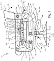
- FIG. 1 is shown in a schematic side view of a chair 1, which comprises a base frame 2, a seat member 3, a back member 4, a spring mechanism 5 and an adjusting device 6.
- the base frame 2 comprises a foot element 2a and a carrier 2b.
- the chair 1 further comprises a front swing arm 7 and a rear swing arm 8 formed as a back connection.
- the foot element 2a is connected to the carrier 2b.
- the back member 4 is articulated via the swing arm 8 and further, the seat member 3 is articulated via the front swing arm 7 on the carrier 2b.
- the front swing arm 7 is pivotable about a pivot axis S7
- the rear swing arm 8 is pivotally connected to the carrier 2b about a pivot axis S8.
- the seat member 3 is pivotally connected to the swing arm 7 about a pivot axis S37. Furthermore, the seat member 3 is pivotally connected about a pivot axis S38 with the back connection 8. The seat member 3 and the back member 4 are rotatably connected to each other via the pivot axis S38.
- the carrier 2b receives the spring mechanism 5.
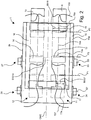
- FIG. 2 is a schematic plan view of the first embodiment of the chair 1 according to the invention shown with hidden back element and hidden from the seat element. From this plan view it can be seen that the chair 1 is formed essentially mirror-symmetrically to a transverse center plane QME. Accordingly, substantially the area of the chair 1 will be described below, which in the representation of the FIG. 2 lies below the transverse center line QME shown as a dashed line. Nevertheless, reference is repeatedly made to components lying above the transverse center plane QME, which as a rule are completely concealed in the side view.
- the carrier 2b comprises a leaf spring 9 and a through the leaf spring 9 in the view of FIG. 1 hidden leaf spring 10. As from the FIG.
- the leaf springs 9, 10 are clamped on one side in receptacles 11, 12 of the carrier 2b.
- the spring mechanism 5 comprises two supports 13, 14, lanes 15, 16, a front stop 17 and a rear stop 18.
- the supports 13, 14 are on the lanes 15 and 16 under the leaf spring 9 and 10 between one with dashed Lines drawn front position or basic position P1 and one with dashed rear position or end position P2 movable so that the leaf spring 9 and 10, a back tilting of the back member 4 in a rotational direction w (see FIG. 1 ), which causes a reclining against the back member 4 person, supported on the rear swing arm 8, which is supported with a stop A8 on the leaf springs 9 and 10.
- the support 13 which in the FIG. 1 in a center position P3 shown by solid lines, optionally in said extreme position P1, in which the support 13 causes only a slight support of the back member 4 by the leaf springs 9, in said extreme position P2, in which the support 13 is a strong support of the Back element 4 effected by the leaf springs 9, and in all intermediate unspecified positions movable.
- As another position P4 is in d FIG. 1 with dashed lines an example lying between the positions P1 and P3 fourth position P4 located.
- the adjusting device 6 is designed as a mechanical adjusting device 101 and comprises an actuator 102 and a transmission means 103.
- the actuator 102 is as Shaft 104 which is rotatable about a rotation axis d104
- the transmission means 103 is designed as a Bowden cable 105.
- the Bowden cable 105 comprises a wire rope 106 and two shells 107, 108.
- the wire rope 106 is fixed to the support 13 and guided between the track 15 and the leaf spring 9 through a through hole 17 a of the front stop 17. Further, the wire rope 106 passes through the first sheath 107, which is laid between the front stop 17 and a first holder 19 with a through hole 19 a.
- the wire 106 exits the first sheath 108, passes through the through-hole 19a, and wraps around the shaft 102 forming the actuator 102, to then enter the second sheath 108 through a through-hole 20a of a second holder 20 which is between the second holder 20 and the rear one Stop 18 is laid. From the second sheath 108, the wire 106 then passes through a through hole 18a made in the rear stop 18 and extends between the track 15 and the leaf spring 9 to the support 13 to which it is fixed. The two holders 19 and 20 are fixed to the foot 2a.
- a drive 21 for the adjusting device 101 is formed by a knob 22 which is connected to the actuator 102 formed as a shaft 104.
- the support 13 is pulled by the wire 106 from its position P3 in the direction of the position P1 or P3.
- a rotation of the rotary knob 22 to the right about the rotation axis d104 the support 13 is pulled by the wire 106 from its position P3 in the direction of the position P2.
- a top 15a of the lane 15 and a bottom 9b of the leaf spring 9 are coordinated so that between them a clearance 23 is formed, which allows a displacement of the support 9 of its position P1 in its position P2, without this with his head 13a on the bottom 9b of the leaf spring 9 grinds and is thereby braked.
- FIGS. 1 and 2 it is provided according to a first embodiment, this form analogous to the adjustment described and to connect the shafts of the two adjusting devices together, so that both supports together adjustable either of one of the knobs are.
- the leaf springs 9, 10 to the receptacles 11, 12 made in each case waisted, so that a width B918, which has the leaf spring 9 in the region of the rear stop 18, at least 1.5 times greater than a width B917 , which has the leaf spring 9 in the region of the front stop 17.
- Two lugs 24, 25 and 25, 27 are arranged laterally on the carrier 2b, by means of which the pivot axes S7, S8 the oscillating arms 7, 8 of the chair 1 are formed.
- FIG. 3 is shown as a chair 201, a second embodiment of a chair according to the invention.
- the adjusting device 206 is likewise designed as a mechanical adjusting device 301, but is designed differently from a technical point of view.
- the adjusting device 301 comprises an actuator 302 and a transmission means 303.
- the actuator 302 is designed as a linear guide 304 and the transmission means 303 is designed as a Bowden cable 305.
- the Bowden cable 305 comprises a wire rope 306 and two sheaths 307, 308.
- the wire rope 306 is fixed to the support 213 and guided between the track 215 and the leaf spring 209 through a through hole 217a of the front stop 217. Further, the wire rope 306 passes through the first sheath 307, which is laid between the front stop 217 and a linear guide housing 229.
- the wire rope 306 exits the first sheath 308 and enters the linear guide housing 229 through an input bore 229a and passes through the linear guide 304 forming the actuator 302, and then passes through an exit bore 229b of the linear guide housing 229 into the second sheath 308 enter, which is laid between the second holder 220 and the rear stop 218. From the second sheath 308, the wire rope 306 then passes through a through hole 218a made in the rear stop 218 and extends between the track 215 and the leaf spring 209 to the support 213 to which it is fixed.
- a drive 221 for the adjusting device 301 is formed by a slide 228 which is guided in the linear guide 304 forming the actuator 302 and is firmly connected to the wire rope 306.
- the support 213 is pulled by the wire rope 306 from its position P203 in the direction of the position or end position P202 to the right.
- the support 213 is pulled to the left from the wire rope 306 from its position P203 toward the position P201.
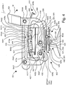
- FIG. 4 is shown as a chair 401, a third embodiment of a chair according to the invention.
- the adjusting device 406 is designed as an electromechanical adjusting device 501.
- the adjusting device 501 comprises an actuator 502 and a transmission means 503.
- the actuator 502 is designed as a linear guide 504 and the transmission means 503 is designed as a Bowden cable 505.
- the Bowden cable 505 comprises a wire rope 506 and two sheaths 507, 508.
- the wire rope 506 is fixed to the support 413 and guided between the track 415 and the leaf spring 409 through a through hole 417a of the front stop 417. Further, the wire rope 506 passes through the first shell 507, which is laid between the front stop 417 and a linear guide housing 429 with an input bore 429 a.
- the wire rope 506 leaves the first sheath 508, enters the linear guide housing 429 through the input bore 429a, and is guided by the linear guide 504 forming the actuator 502, to then enter the second sheath 508 through an exit bore 429b of the linear guide housing 429, which intervenes the linear guide housing 429 and the rear stop 418 is laid. From the second sheath 508, the wire rope 506 then passes through a through hole 418a formed in the rear stopper 418 and extends between the track 415 and the leaf spring 409 to the abutment 413 to which it is fixed.
- a drive 421 for the adjusting device 501 is formed by an electric drive 430, which is guided in the linear guide 504 forming the actuator 502.
- the electric drive 430 is formed with a part of its housing 431 as a slide 432.
- the electric drive 430 includes a gear 433, which drives this with its motor shaft 434.
- the linear guide housing 429 includes a rack 429 c, in which the electric drive 430 engages with its gear 433.
- the electric drive 430 guided in the linear guide 504, to which the wire rope 506 is firmly connected can move to the left or right in the linear guide 504.
- the support 413 By a movement of the electric drive 430 to the left, the support 413 is pulled by the wire rope 506 from its position P403 to the right in the direction of the position or end position P402. By a movement of the electric drive 430 to the right, the support 413 is pulled by the wire rope 506 from its position P403 to the left in the direction of the position or basic position P401.
- the keys are arranged in a circuit between a rechargeable energy storage 435 and the electric drive 430.
- the chair 401 also includes an electric generator 436, which by a relative movement between the nose 425 (see FIG. 5 ) and the rear swing arm 408 generates electrical energy and feeds them into the rechargeable energy storage 435.
- an electric generator 436 which by a relative movement between the nose 425 (see FIG. 5 ) and the rear swing arm 408 generates electrical energy and feeds them into the rechargeable energy storage 435.
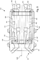
- FIG. 5 is a schematic plan view of the third embodiment of the chair according to the invention 401 shown with hidden back element and hidden from the seat element. It can be seen from this plan view that the chair 401 is formed substantially mirror-symmetrically to a transverse center plane QME. Accordingly, substantially the area of the chair 1 will be described below, which in the representation of the FIG. 2 lies below the transverse center line QME shown as a dashed line. Nevertheless, reference is repeatedly made to components lying above the transverse center plane QME, which as a rule are completely concealed in the side view.
- the first leaf spring 409 and the second leaf spring 459 form a spring assembly 461.
- the first leaf spring 410 and the second leaf spring 459 form another spring assembly 462.
- the second leaf springs 459 and 460 are each assigned their own support 463 and 464, respectively.
- the second leaf springs 459, 460 serve to the back member 404 (see FIG. 4 ) in its initial position or basic position or rest position S404.1, in which it in the FIG.
- leaf springs 409 and 459 and 410 and 460, respectively, which form the spring assemblies 461 and 462 are connected at junctions 467, 468 and constitute the respective one-piece spring assemblies 461 and 462.
- the first leaf spring 409 or 410 of these spring assemblies 461 and 462 are formed in particular adjacent to the connection points 467 and 468 waisted.
- supports 413, 414 which are arranged under the leaf springs 409, 410, the description of FIG. 2 directed.
- the support 413 is adjustable by the first adjusting device 501 and the second support 463 is, if an adjustability is provided, adjustable by a second adjusting device 551.
- FIGS. 6 and 7 is in schematic views with reference to the FIGS. 1 . 3 and 4 shown that the lanes 15, 215, 415 have a curved course, which is adapted to a curved course of the leaf springs 9, 10 and 209, 210 and 409, 410.
- the adjustment is made so that the supports 13 and 213 or 413 or 14 or 214 or 414, which initially close to the recordings 11 and 211 and 411 for the leaf springs 9, 10 and 209, 210 and 409, 410 located, from a in the FIG. 6 shown position P1 or P201 or P401 in one in the FIG.
- the support is 13 or 213 or 413 in a spring force of the leaf spring 9 or 209 or 409 causing position.
- the roadway 15 or 215 or 415 thus forms with its upper side 15a or 215a or 415a a curved surface F, which is adapted to a curved course of the respectively associated leaf spring 9 or 209 or 409, that between the Lane 15 or 215 or 415 and the bottom 9b or 209b or 409b educated movement space R a by the leaf spring 9 or 209 or 409 unhindered process of the support 13 or 213 or 413 between the first position P1 and P201 or P401 of the support 13 or 213 or 413 and the second position P2 or P202 or P402 of the support 13 or 213 or 413 permits, provided the back element 4 or 204 or 404 free from stress is a against the back member 4 or 204 or 404 reclining user. Furthermore, a distance A1 or A201 or A401 respectively measured in the radial direction between the roadway 16 or 216 or
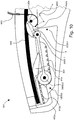
- FIGS. 8 to 11 show two schematic side views and details of these side views of a fourth embodiment of a chair 601 according to the invention in a setting for persons with low weight ( FIG. 8 . 10 ) and a setting for persons with high weight ( FIG. 9 . 10 ).
- the chair 601 comprises a base frame 602, which is shown only partially. To this base 602, in analogy to that in FIG FIG. 1 shown embodiment, a not shown seat element and a not shown back element articulated. Furthermore, the chair 601 comprises a spring mechanism 605 and an adjusting device 606.
- the base frame 602 comprises a partially illustrated foot element 602a and a carrier 602b.
- the chair 1 also comprises a rear swing arm 608 designed as a back connection, which is supported on a leaf spring 609 clamped in the base frame 602. A bias of the leaf spring 609 is determined by the positions P601, P602, which occupies a support 613 on a between the leaf spring 609 and a formed on the base 602 roadway 615 (see FIGS. 8 and 9 ).
- the support 613 in the front position P601, which is also referred to as the basic position, and in the FIG. 9 the support 613 is in a rear position P602, which is also referred to as the end position.
- the swing arm 608 undergoes only a comparatively weak support for supporting the back element (not shown) against a person leaning back by the leaf spring 609 and is therefore set for persons with low body weight, for example less than 50 kg.
- the swing arm 608 undergoes only a comparatively strong support for supporting the back element (not shown) against a person leaning back by the leaf spring 609 and is therefore adjusted for persons with a high body weight, for example over 90 kg.
- the support 613 can be moved from the basic position P601 into the end position P602 and back and can also move into any intermediate position lying between these positions P601, P602.
- the adjusting device 606 comprises an actuator 651 and a Transmission means 652.
- the actuator 651 includes a linear guide 651a and a slider 651b.
- the transmission means 652 comprises a Bowden cable 653, a pivot lever 654, a connecting rod 655 and a Wälzrad 656 with a toothing 656 a.
- the pivot lever 654 is pivotally mounted about a pivot axis L654 on the support 602b of the base frame 602 and by the actuator 651 by means of the Bowden cable 653, which is connected to the actuator 651 and the pivot lever 654 pivotable about a pivot angle ⁇ by more than 90 °.
- the Bowden cable 653 which can be actuated manually by means of the slide 651b serving as the drive 621, acts eccentrically on the pivoting lever 654 at a point of application P653 eccentrically to the pivot axis L654 and is on a path B653 on the pivoting lever 654 running circularly about the pivot axis L654 guided.
- a free end E654 of the pivoting lever 654 is pivotally connected about a rotational axis D655-1 to a first end 655-1 of the connecting rod 655. From a ratio in which a first distance a (see FIG. 10 ) between the pivot axis L654 and the point of application P654 and a second distance b (see FIG.
- the first transmission ratio UE601 is approximately 1: 2.
- the rolling gear 656 with its toothing 656a is arranged rotatably about a rotation axis D655-2.
- the Wälzrad 656 is freely rotatable relative to the connecting rod 655 about the rotation axis D655-2.
- the Wälzrad 656 rests on a rack 657, which is formed on the carrier 602 b of the base frame 602. In a pivoting movement of the pivot lever 654 to the left about the pivot axis L654, the Wälzrad 656 is pulled by the connecting rod 655 via the rack 657 and this rolling on this.
- the rack 657 opposite the support 613 is arranged, which a rack 613a, in which the Wälzrad 656 also engages with its teeth 656a. If the rear swing arm 608 of the chair 601 is unloaded, the support 613 is unhindered by the leaf spring 609 movable under this.
- the Wälzrad 656 so cooperates with the support 613 and the rack 613a that the Wälzrad 656, for example, in a movement which is perpendicular to the course and in the direction of the pivot axis L654 of the pivot lever 654, the support 613 entrains in the direction of the pivot axis L654 and at the same time still promotes the Schwenkachs L654 out.
- a second transmission ratio UE602 is 1: 2, so that a total transmission ratio of 1: 4 results. If the rolling gear 656 moves from its position S602, which it occupies when the support 613 is in the position P602, by turning the pivot lever 654 clockwise about the pivot axis L654 away from the pivot axis L654, the support 613 also becomes pivotal axis L654 moved away and promoted away so that it is at the end of the pivoting movement in the position P601 again. The Wälzrad 656 is then in a position S601 (see FIG. 8 ).
Landscapes
- Health & Medical Sciences (AREA)
- Dentistry (AREA)
- General Health & Medical Sciences (AREA)
- Chairs Characterized By Structure (AREA)
- Chairs For Special Purposes, Such As Reclining Chairs (AREA)
Priority Applications (1)
| Application Number | Priority Date | Filing Date | Title |
|---|---|---|---|
| PL17710891T PL3429432T3 (pl) | 2016-03-14 | 2017-03-14 | Krzesło |
Applications Claiming Priority (2)
| Application Number | Priority Date | Filing Date | Title |
|---|---|---|---|
| DE102016104636 | 2016-03-14 | ||
| PCT/EP2017/056004 WO2017157945A1 (de) | 2016-03-14 | 2017-03-14 | Stuhl |
Publications (2)
| Publication Number | Publication Date |
|---|---|
| EP3429432A1 EP3429432A1 (de) | 2019-01-23 |
| EP3429432B1 true EP3429432B1 (de) | 2019-11-20 |
Family
ID=58314206
Family Applications (1)
| Application Number | Title | Priority Date | Filing Date |
|---|---|---|---|
| EP17710891.7A Active EP3429432B1 (de) | 2016-03-14 | 2017-03-14 | Stuhl |
Country Status (6)
| Country | Link |
|---|---|
| US (2) | US10653249B2 (pl) |
| EP (1) | EP3429432B1 (pl) |
| DE (1) | DE102017105398A1 (pl) |
| ES (1) | ES2773199T3 (pl) |
| PL (1) | PL3429432T3 (pl) |
| WO (1) | WO2017157945A1 (pl) |
Families Citing this family (12)
| Publication number | Priority date | Publication date | Assignee | Title |
|---|---|---|---|---|
| US11596235B2 (en) * | 2015-02-11 | 2023-03-07 | Aaron DeJule | Apparatus with weight responsive changeable adjusting characteristics |
| DE102017105398A1 (de) * | 2016-03-14 | 2017-09-14 | Burkhard Schmitz | Stuhl |
| DE102016124160B4 (de) * | 2016-12-13 | 2019-08-29 | Stabilus Gmbh | Stuhlsäulenanordnung |
| CN110658863B (zh) * | 2019-11-14 | 2025-04-25 | 深圳体感音悦科技有限公司 | 一种调频调幅的放松椅 |
| WO2022173799A1 (en) | 2021-02-10 | 2022-08-18 | Steelcase Inc. | Body support structure |
| CN113729426B (zh) * | 2021-05-27 | 2025-11-28 | 广东联友办公家具有限公司 | 一种座椅底盘及座椅 |
| CN113729428B (zh) * | 2021-05-27 | 2025-06-27 | 广东联友办公家具有限公司 | 一种电控底盘及座椅 |
| US12042054B2 (en) | 2022-05-19 | 2024-07-23 | Mingqian Yi | Multifunctional outdoor leisure rotary chair |
| CN116326947A (zh) * | 2023-03-21 | 2023-06-27 | 广东联友办公家具有限公司 | 座椅调节模组、座椅框体及座椅 |
| US20240315448A1 (en) | 2023-03-23 | 2024-09-26 | Fellowes, Inc. | Chair tilt system with leaf spring |
| NL2035885B1 (en) | 2023-09-26 | 2025-04-01 | Koninklijke Ahrend B V | An office chair with a weight adjustment mechanism |
| DE102024116489A1 (de) * | 2024-06-12 | 2025-12-18 | Burkhard Schmitz | Stuhl und Betriebsverfahren für einen Stuhl |
Family Cites Families (41)
| Publication number | Priority date | Publication date | Assignee | Title |
|---|---|---|---|---|
| US4889385A (en) * | 1988-03-09 | 1989-12-26 | American Seating Company | Chair seat-and-back support |
| US5035466A (en) * | 1989-04-03 | 1991-07-30 | Krueger International, Inc. | Ergonomic chair |
| US4911501A (en) * | 1989-06-09 | 1990-03-27 | Harter Corporation | Suspension mechanism for connecting chair backs and seats to a pedestal |
| DE9003589U1 (de) * | 1990-03-28 | 1991-07-25 | Fritz Hansens Eft. A/S, Alleroed | Sitzmechanik |
| US5048893A (en) * | 1990-07-16 | 1991-09-17 | Benjamin Cowan | Ergonomic chair |
| US5288138A (en) * | 1990-08-10 | 1994-02-22 | Stulik Edward L | Reclining chair |
| JP2919131B2 (ja) * | 1991-10-22 | 1999-07-12 | 株式会社イトーキクレビオ | 椅子の傾動制御装置 |
| IL103477A0 (en) * | 1992-10-20 | 1993-03-15 | Paltechnica Nitzanim | Office and like chairs |
| US5603551A (en) * | 1996-01-16 | 1997-02-18 | Sheehan; Kelly | Gravitational resistant positional chair |
| US6250715B1 (en) * | 1998-01-21 | 2001-06-26 | Herman Miller, Inc. | Chair |
| US6027168A (en) * | 1998-06-05 | 2000-02-22 | Leggett & Platt, Inc. | Chair seat horizontal adjustment mechanism |
| US6135556A (en) * | 1998-06-05 | 2000-10-24 | Teknion Furniture Systems Inc. | Seat adjustment mechanism |
| SE512936C2 (sv) * | 1998-09-10 | 2000-06-05 | Bertil Jonsson | Stol |
| GB0010238D0 (en) * | 2000-04-28 | 2000-06-14 | Northeastern Components Intern | Locking mechanism for chair and pushbutton control therefor |
| IT1320420B1 (it) * | 2000-06-09 | 2003-11-26 | Pro Cord Srl | Sedia con sedile oscillante. |
| US6634711B2 (en) * | 2001-06-15 | 2003-10-21 | Hon Technology Inc. | Adjustable chair seat with locking mechanism |
| US6688692B2 (en) * | 2001-06-15 | 2004-02-10 | Hon Technology Inc. | Locking device for chair seat horizontal adjustment mechanism |
| CA2472070C (en) * | 2002-02-13 | 2010-03-16 | Herman Miller, Inc. | Tilt chair having a flexible back, adjustable armrests and adjustable seat depth, and methods for the use thereof |
| DE10249335A1 (de) * | 2002-10-22 | 2004-05-06 | Interstuhl Büromöbel GmbH & Co. KG | Vorrichtung zur Verstellung der Sitztiefe eines Stuhls |
| US7341233B2 (en) * | 2003-09-19 | 2008-03-11 | L & P Property Management Company | Horizontal adjustment mechanism for use on a chair seat |
| US6994400B2 (en) * | 2003-12-30 | 2006-02-07 | Hni Technologies Inc. | Chair with adjustable seat depth |
| US7273253B2 (en) * | 2004-06-09 | 2007-09-25 | Kimball International, Inc. | Chair ride mechanism with tension assembly |
| US6986550B2 (en) * | 2004-06-12 | 2006-01-17 | Krueger International, Inc. | Seat slide assembly |
| US7380881B2 (en) * | 2004-06-15 | 2008-06-03 | Freed William L | Ergonomically responsive chair |
| US7172250B2 (en) * | 2004-09-27 | 2007-02-06 | Yao-Chuan Wu | Adjustable chassis for chair |
| TWI260977B (en) * | 2005-02-05 | 2006-09-01 | Tung Yu O A Co Ltd | Chair seat with slipping function |
| US7806478B1 (en) * | 2006-01-04 | 2010-10-05 | Sava Cvek | Task chair with dual tilting capabilities |
| WO2007110732A2 (en) * | 2006-03-24 | 2007-10-04 | Herman Miller Inc. | Piece of furniture |
| PT1908374E (pt) * | 2006-10-06 | 2009-05-18 | Stoll Giroflex Ag | Cadeira de escritório sincronizada |
| BRPI0823267A2 (pt) * | 2007-01-29 | 2013-09-24 | Miller Herman Inc | estrutura de assento e mÉtodos para uso da mesma |
| US20080258531A1 (en) * | 2007-04-23 | 2008-10-23 | Wu-Chin Lu | Chair having a seat whose position is adjustable |
| BRPI0817111A2 (pt) * | 2007-09-20 | 2015-03-31 | Miller Herman Inc | Estrutura de suporte de corpo |
| US9216673B2 (en) * | 2008-03-05 | 2015-12-22 | Milsco Manufacturing Company, A Unit Of Jason Incorporated | Low profile seat position adjustment system |
| US8303035B2 (en) * | 2010-09-24 | 2012-11-06 | Yun-Chien Hsiao | Chair assembly with a seat-adjusting device |
| CN202160996U (zh) * | 2011-07-04 | 2012-03-14 | 陈育成 | 一种结构改进的多功能底盘 |
| CN202354902U (zh) * | 2011-09-15 | 2012-08-01 | 陈育成 | 座椅底盘 |
| JP6325981B2 (ja) * | 2011-10-21 | 2018-05-16 | リ, ジェ ヒョンLEE, Jae hyun | スライダー方式を利用した矯正椅子 |
| US8991921B2 (en) * | 2012-07-20 | 2015-03-31 | Steelcase Inc. | Seating unit with seat position and depth adjustment assembly |
| DE102013005861A1 (de) | 2013-04-08 | 2014-10-09 | Burkhard Schmitz | Mechanikbaugruppe für einen Stuhl und Stuhl mit einer derartigen Mechanikbaugruppe |
| US9560917B2 (en) * | 2014-11-26 | 2017-02-07 | Steelcase Inc. | Recline adjustment system for chair |
| DE102017105398A1 (de) * | 2016-03-14 | 2017-09-14 | Burkhard Schmitz | Stuhl |
-
2017
- 2017-03-14 DE DE102017105398.0A patent/DE102017105398A1/de active Pending
- 2017-03-14 EP EP17710891.7A patent/EP3429432B1/de active Active
- 2017-03-14 PL PL17710891T patent/PL3429432T3/pl unknown
- 2017-03-14 WO PCT/EP2017/056004 patent/WO2017157945A1/de not_active Ceased
- 2017-03-14 ES ES17710891T patent/ES2773199T3/es active Active
-
2018
- 2018-09-13 US US16/129,934 patent/US10653249B2/en active Active
-
2020
- 2020-04-09 US US16/844,296 patent/US11166569B2/en active Active
Non-Patent Citations (1)
| Title |
|---|
| None * |
Also Published As
| Publication number | Publication date |
|---|---|
| PL3429432T3 (pl) | 2020-06-01 |
| EP3429432A1 (de) | 2019-01-23 |
| US20200229614A1 (en) | 2020-07-23 |
| DE102017105398A1 (de) | 2017-09-14 |
| US20190029440A1 (en) | 2019-01-31 |
| WO2017157945A1 (de) | 2017-09-21 |
| US10653249B2 (en) | 2020-05-19 |
| US11166569B2 (en) | 2021-11-09 |
| ES2773199T3 (es) | 2020-07-09 |
Similar Documents
| Publication | Publication Date | Title |
|---|---|---|
| EP3429432B1 (de) | Stuhl | |
| DE19848603B4 (de) | Verstellbare Sitzaufhängung | |
| DE3888962T2 (de) | Anordnung für einen einstellbaren sessel. | |
| DE102015106386B4 (de) | Armlehnenanordnung für einen Sitz, insbesondere für einen Fahrzeugsitz und Fahrzeugsitz | |
| DE102007022015A1 (de) | Mechanik für einen Bürostuhl | |
| EP3023296B1 (de) | Armlehnenanordnung für einen sitz, insbesondere für einen fahrzeugsitz | |
| DE102015214297B4 (de) | Elektrisch verstellbarer Bürostuhl | |
| DE102016121203A1 (de) | Vorrichtung zum Unterstützen eines Armes | |
| DE102014115126A1 (de) | Elektromotorisch verstellbare Stützeinrichtung | |
| DE202013100574U1 (de) | Mechanik für einen Bürostuhl | |
| DE102015214301A1 (de) | Möbelstück und Stellanordnung, insbesondere für eine Lehnenverstellung | |
| EP2926690A1 (de) | Mechanik für einen Bürostuhl | |
| EP3387957A1 (de) | Synchronmechanik für einen bürostuhl | |
| DE102014115125A1 (de) | Elektromotorische Verstellvorrichtung | |
| DE102010013857B4 (de) | Kopfstütze und Fahrzeugsitz | |
| EP3023297B1 (de) | Fahrzeugsitz mit verschwenkbarer rückenlehne inklusive armlehne | |
| DE202019104366U1 (de) | Fahrzeugsitz mit einer Sitztiefenverstellung, insbesondere mit einer Bein- und/oder Fußablage | |
| DE202009009612U1 (de) | Stuhl | |
| EP2994021B1 (de) | Lattenrost mit einem elektromotorischen möbelantrieb | |
| EP2989931B1 (de) | Sitzmöbel | |
| EP3649893A1 (de) | Einstellen des schwenkwiderstandes einer verschwenkbaren komponente eines sitzmöbels | |
| DE102007009283A1 (de) | Verstellbare Armauflage | |
| EP4115768A1 (de) | Mechanik für einen stuhl | |
| WO2010028412A1 (de) | Vorrichtung zur verstellung des schwenkwiderstandes einer rückenlehne | |
| DE102010026787A1 (de) | Mechanik für einen Bürostuhl |
Legal Events
| Date | Code | Title | Description |
|---|---|---|---|
| STAA | Information on the status of an ep patent application or granted ep patent |
Free format text: STATUS: UNKNOWN |
|
| STAA | Information on the status of an ep patent application or granted ep patent |
Free format text: STATUS: THE INTERNATIONAL PUBLICATION HAS BEEN MADE |
|
| PUAI | Public reference made under article 153(3) epc to a published international application that has entered the european phase |
Free format text: ORIGINAL CODE: 0009012 |
|
| STAA | Information on the status of an ep patent application or granted ep patent |
Free format text: STATUS: REQUEST FOR EXAMINATION WAS MADE |
|
| 17P | Request for examination filed |
Effective date: 20180907 |
|
| AK | Designated contracting states |
Kind code of ref document: A1 Designated state(s): AL AT BE BG CH CY CZ DE DK EE ES FI FR GB GR HR HU IE IS IT LI LT LU LV MC MK MT NL NO PL PT RO RS SE SI SK SM TR |
|
| AX | Request for extension of the european patent |
Extension state: BA ME |
|
| DAV | Request for validation of the european patent (deleted) | ||
| DAX | Request for extension of the european patent (deleted) | ||
| GRAP | Despatch of communication of intention to grant a patent |
Free format text: ORIGINAL CODE: EPIDOSNIGR1 |
|
| STAA | Information on the status of an ep patent application or granted ep patent |
Free format text: STATUS: GRANT OF PATENT IS INTENDED |
|
| INTG | Intention to grant announced |
Effective date: 20190731 |
|
| GRAS | Grant fee paid |
Free format text: ORIGINAL CODE: EPIDOSNIGR3 |
|
| GRAA | (expected) grant |
Free format text: ORIGINAL CODE: 0009210 |
|
| STAA | Information on the status of an ep patent application or granted ep patent |
Free format text: STATUS: THE PATENT HAS BEEN GRANTED |
|
| AK | Designated contracting states |
Kind code of ref document: B1 Designated state(s): AL AT BE BG CH CY CZ DE DK EE ES FI FR GB GR HR HU IE IS IT LI LT LU LV MC MK MT NL NO PL PT RO RS SE SI SK SM TR |
|
| REG | Reference to a national code |
Ref country code: GB Ref legal event code: FG4D Free format text: NOT ENGLISH |
|
| REG | Reference to a national code |
Ref country code: CH Ref legal event code: EP |
|
| REG | Reference to a national code |
Ref country code: DE Ref legal event code: R096 Ref document number: 502017002935 Country of ref document: DE |
|
| REG | Reference to a national code |
Ref country code: IE Ref legal event code: FG4D Free format text: LANGUAGE OF EP DOCUMENT: GERMAN |
|
| REG | Reference to a national code |
Ref country code: AT Ref legal event code: REF Ref document number: 1203176 Country of ref document: AT Kind code of ref document: T Effective date: 20191215 |
|
| REG | Reference to a national code |
Ref country code: NL Ref legal event code: FP |
|
| REG | Reference to a national code |
Ref country code: LT Ref legal event code: MG4D |
|
| PG25 | Lapsed in a contracting state [announced via postgrant information from national office to epo] |
Ref country code: SE Free format text: LAPSE BECAUSE OF FAILURE TO SUBMIT A TRANSLATION OF THE DESCRIPTION OR TO PAY THE FEE WITHIN THE PRESCRIBED TIME-LIMIT Effective date: 20191120 Ref country code: LV Free format text: LAPSE BECAUSE OF FAILURE TO SUBMIT A TRANSLATION OF THE DESCRIPTION OR TO PAY THE FEE WITHIN THE PRESCRIBED TIME-LIMIT Effective date: 20191120 Ref country code: NO Free format text: LAPSE BECAUSE OF FAILURE TO SUBMIT A TRANSLATION OF THE DESCRIPTION OR TO PAY THE FEE WITHIN THE PRESCRIBED TIME-LIMIT Effective date: 20200220 Ref country code: GR Free format text: LAPSE BECAUSE OF FAILURE TO SUBMIT A TRANSLATION OF THE DESCRIPTION OR TO PAY THE FEE WITHIN THE PRESCRIBED TIME-LIMIT Effective date: 20200221 Ref country code: LT Free format text: LAPSE BECAUSE OF FAILURE TO SUBMIT A TRANSLATION OF THE DESCRIPTION OR TO PAY THE FEE WITHIN THE PRESCRIBED TIME-LIMIT Effective date: 20191120 Ref country code: BG Free format text: LAPSE BECAUSE OF FAILURE TO SUBMIT A TRANSLATION OF THE DESCRIPTION OR TO PAY THE FEE WITHIN THE PRESCRIBED TIME-LIMIT Effective date: 20200220 Ref country code: FI Free format text: LAPSE BECAUSE OF FAILURE TO SUBMIT A TRANSLATION OF THE DESCRIPTION OR TO PAY THE FEE WITHIN THE PRESCRIBED TIME-LIMIT Effective date: 20191120 |
|
| PG25 | Lapsed in a contracting state [announced via postgrant information from national office to epo] |
Ref country code: RS Free format text: LAPSE BECAUSE OF FAILURE TO SUBMIT A TRANSLATION OF THE DESCRIPTION OR TO PAY THE FEE WITHIN THE PRESCRIBED TIME-LIMIT Effective date: 20191120 Ref country code: IS Free format text: LAPSE BECAUSE OF FAILURE TO SUBMIT A TRANSLATION OF THE DESCRIPTION OR TO PAY THE FEE WITHIN THE PRESCRIBED TIME-LIMIT Effective date: 20200320 Ref country code: HR Free format text: LAPSE BECAUSE OF FAILURE TO SUBMIT A TRANSLATION OF THE DESCRIPTION OR TO PAY THE FEE WITHIN THE PRESCRIBED TIME-LIMIT Effective date: 20191120 |
|
| PG25 | Lapsed in a contracting state [announced via postgrant information from national office to epo] |
Ref country code: AL Free format text: LAPSE BECAUSE OF FAILURE TO SUBMIT A TRANSLATION OF THE DESCRIPTION OR TO PAY THE FEE WITHIN THE PRESCRIBED TIME-LIMIT Effective date: 20191120 |
|
| REG | Reference to a national code |
Ref country code: ES Ref legal event code: FG2A Ref document number: 2773199 Country of ref document: ES Kind code of ref document: T3 Effective date: 20200709 |
|
| PG25 | Lapsed in a contracting state [announced via postgrant information from national office to epo] |
Ref country code: EE Free format text: LAPSE BECAUSE OF FAILURE TO SUBMIT A TRANSLATION OF THE DESCRIPTION OR TO PAY THE FEE WITHIN THE PRESCRIBED TIME-LIMIT Effective date: 20191120 Ref country code: DK Free format text: LAPSE BECAUSE OF FAILURE TO SUBMIT A TRANSLATION OF THE DESCRIPTION OR TO PAY THE FEE WITHIN THE PRESCRIBED TIME-LIMIT Effective date: 20191120 Ref country code: PT Free format text: LAPSE BECAUSE OF FAILURE TO SUBMIT A TRANSLATION OF THE DESCRIPTION OR TO PAY THE FEE WITHIN THE PRESCRIBED TIME-LIMIT Effective date: 20200412 Ref country code: CZ Free format text: LAPSE BECAUSE OF FAILURE TO SUBMIT A TRANSLATION OF THE DESCRIPTION OR TO PAY THE FEE WITHIN THE PRESCRIBED TIME-LIMIT Effective date: 20191120 Ref country code: RO Free format text: LAPSE BECAUSE OF FAILURE TO SUBMIT A TRANSLATION OF THE DESCRIPTION OR TO PAY THE FEE WITHIN THE PRESCRIBED TIME-LIMIT Effective date: 20191120 |
|
| REG | Reference to a national code |
Ref country code: DE Ref legal event code: R097 Ref document number: 502017002935 Country of ref document: DE |
|
| PG25 | Lapsed in a contracting state [announced via postgrant information from national office to epo] |
Ref country code: SK Free format text: LAPSE BECAUSE OF FAILURE TO SUBMIT A TRANSLATION OF THE DESCRIPTION OR TO PAY THE FEE WITHIN THE PRESCRIBED TIME-LIMIT Effective date: 20191120 Ref country code: SM Free format text: LAPSE BECAUSE OF FAILURE TO SUBMIT A TRANSLATION OF THE DESCRIPTION OR TO PAY THE FEE WITHIN THE PRESCRIBED TIME-LIMIT Effective date: 20191120 |
|
| PLBE | No opposition filed within time limit |
Free format text: ORIGINAL CODE: 0009261 |
|
| STAA | Information on the status of an ep patent application or granted ep patent |
Free format text: STATUS: NO OPPOSITION FILED WITHIN TIME LIMIT |
|
| 26N | No opposition filed |
Effective date: 20200821 |
|
| PG25 | Lapsed in a contracting state [announced via postgrant information from national office to epo] |
Ref country code: MC Free format text: LAPSE BECAUSE OF FAILURE TO SUBMIT A TRANSLATION OF THE DESCRIPTION OR TO PAY THE FEE WITHIN THE PRESCRIBED TIME-LIMIT Effective date: 20191120 |
|
| REG | Reference to a national code |
Ref country code: CH Ref legal event code: PL |
|
| PG25 | Lapsed in a contracting state [announced via postgrant information from national office to epo] |
Ref country code: SI Free format text: LAPSE BECAUSE OF FAILURE TO SUBMIT A TRANSLATION OF THE DESCRIPTION OR TO PAY THE FEE WITHIN THE PRESCRIBED TIME-LIMIT Effective date: 20191120 |
|
| REG | Reference to a national code |
Ref country code: BE Ref legal event code: MM Effective date: 20200331 |
|
| PG25 | Lapsed in a contracting state [announced via postgrant information from national office to epo] |
Ref country code: LU Free format text: LAPSE BECAUSE OF NON-PAYMENT OF DUE FEES Effective date: 20200314 |
|
| PG25 | Lapsed in a contracting state [announced via postgrant information from national office to epo] |
Ref country code: CH Free format text: LAPSE BECAUSE OF NON-PAYMENT OF DUE FEES Effective date: 20200331 Ref country code: LI Free format text: LAPSE BECAUSE OF NON-PAYMENT OF DUE FEES Effective date: 20200331 Ref country code: IE Free format text: LAPSE BECAUSE OF NON-PAYMENT OF DUE FEES Effective date: 20200314 |
|
| PG25 | Lapsed in a contracting state [announced via postgrant information from national office to epo] |
Ref country code: BE Free format text: LAPSE BECAUSE OF NON-PAYMENT OF DUE FEES Effective date: 20200331 |
|
| PG25 | Lapsed in a contracting state [announced via postgrant information from national office to epo] |
Ref country code: TR Free format text: LAPSE BECAUSE OF FAILURE TO SUBMIT A TRANSLATION OF THE DESCRIPTION OR TO PAY THE FEE WITHIN THE PRESCRIBED TIME-LIMIT Effective date: 20191120 Ref country code: MT Free format text: LAPSE BECAUSE OF FAILURE TO SUBMIT A TRANSLATION OF THE DESCRIPTION OR TO PAY THE FEE WITHIN THE PRESCRIBED TIME-LIMIT Effective date: 20191120 Ref country code: CY Free format text: LAPSE BECAUSE OF FAILURE TO SUBMIT A TRANSLATION OF THE DESCRIPTION OR TO PAY THE FEE WITHIN THE PRESCRIBED TIME-LIMIT Effective date: 20191120 |
|
| PG25 | Lapsed in a contracting state [announced via postgrant information from national office to epo] |
Ref country code: MK Free format text: LAPSE BECAUSE OF FAILURE TO SUBMIT A TRANSLATION OF THE DESCRIPTION OR TO PAY THE FEE WITHIN THE PRESCRIBED TIME-LIMIT Effective date: 20191120 |
|
| REG | Reference to a national code |
Ref country code: AT Ref legal event code: MM01 Ref document number: 1203176 Country of ref document: AT Kind code of ref document: T Effective date: 20220314 |
|
| PG25 | Lapsed in a contracting state [announced via postgrant information from national office to epo] |
Ref country code: AT Free format text: LAPSE BECAUSE OF NON-PAYMENT OF DUE FEES Effective date: 20220314 |
|
| REG | Reference to a national code |
Ref country code: DE Ref legal event code: R082 Ref document number: 502017002935 Country of ref document: DE Representative=s name: RAVENSPAT PATENTANWAELTE PARTNERSCHAFT MBB, DE |
|
| PGFP | Annual fee paid to national office [announced via postgrant information from national office to epo] |
Ref country code: DE Payment date: 20250319 Year of fee payment: 9 |
|
| PGFP | Annual fee paid to national office [announced via postgrant information from national office to epo] |
Ref country code: NL Payment date: 20250324 Year of fee payment: 9 |
|
| PGFP | Annual fee paid to national office [announced via postgrant information from national office to epo] |
Ref country code: FR Payment date: 20250324 Year of fee payment: 9 Ref country code: PL Payment date: 20250304 Year of fee payment: 9 |
|
| PGFP | Annual fee paid to national office [announced via postgrant information from national office to epo] |
Ref country code: GB Payment date: 20250324 Year of fee payment: 9 |
|
| PGFP | Annual fee paid to national office [announced via postgrant information from national office to epo] |
Ref country code: ES Payment date: 20250416 Year of fee payment: 9 |
|
| PGFP | Annual fee paid to national office [announced via postgrant information from national office to epo] |
Ref country code: IT Payment date: 20250331 Year of fee payment: 9 |