EP3427852A1 - Verfahren zur herstellung von stahlrohren mit unterschiedlichen dicken und stahlrohr mit unterschiedlichen dicken - Google Patents
Verfahren zur herstellung von stahlrohren mit unterschiedlichen dicken und stahlrohr mit unterschiedlichen dicken Download PDFInfo
- Publication number
- EP3427852A1 EP3427852A1 EP17762824.5A EP17762824A EP3427852A1 EP 3427852 A1 EP3427852 A1 EP 3427852A1 EP 17762824 A EP17762824 A EP 17762824A EP 3427852 A1 EP3427852 A1 EP 3427852A1
- Authority
- EP
- European Patent Office
- Prior art keywords
- raw pipe
- diameter
- wall thickness
- steel pipe
- pipe
- Prior art date
- Legal status (The legal status is an assumption and is not a legal conclusion. Google has not performed a legal analysis and makes no representation as to the accuracy of the status listed.)
- Withdrawn
Links
Images






Classifications
-
- B—PERFORMING OPERATIONS; TRANSPORTING
- B21—MECHANICAL METAL-WORKING WITHOUT ESSENTIALLY REMOVING MATERIAL; PUNCHING METAL
- B21C—MANUFACTURE OF METAL SHEETS, WIRE, RODS, TUBES, PROFILES OR LIKE SEMI-MANUFACTURED PRODUCTS OTHERWISE THAN BY ROLLING; AUXILIARY OPERATIONS USED IN CONNECTION WITH METAL-WORKING WITHOUT ESSENTIALLY REMOVING MATERIAL
- B21C37/00—Manufacture of metal sheets, rods, wire, tubes, profiles or like semi-manufactured products, not otherwise provided for; Manufacture of tubes of special shape
- B21C37/06—Manufacture of metal sheets, rods, wire, tubes, profiles or like semi-manufactured products, not otherwise provided for; Manufacture of tubes of special shape of tubes or metal hoses; Combined procedures for making tubes, e.g. for making multi-wall tubes
- B21C37/15—Making tubes of special shape; Making tube fittings
- B21C37/16—Making tubes with varying diameter in longitudinal direction
-
- B—PERFORMING OPERATIONS; TRANSPORTING
- B21—MECHANICAL METAL-WORKING WITHOUT ESSENTIALLY REMOVING MATERIAL; PUNCHING METAL
- B21C—MANUFACTURE OF METAL SHEETS, WIRE, RODS, TUBES, PROFILES OR LIKE SEMI-MANUFACTURED PRODUCTS OTHERWISE THAN BY ROLLING; AUXILIARY OPERATIONS USED IN CONNECTION WITH METAL-WORKING WITHOUT ESSENTIALLY REMOVING MATERIAL
- B21C1/00—Manufacture of metal sheets, wire, rods, tubes or like semi-manufactured products by drawing
- B21C1/16—Metal drawing by machines or apparatus in which the drawing action is effected by means other than drums, e.g. by a longitudinally-moved carriage pulling or pushing the work or stock for making metal sheets, rods or tubes
- B21C1/22—Metal drawing by machines or apparatus in which the drawing action is effected by means other than drums, e.g. by a longitudinally-moved carriage pulling or pushing the work or stock for making metal sheets, rods or tubes specially adapted for making tubular articles
- B21C1/24—Metal drawing by machines or apparatus in which the drawing action is effected by means other than drums, e.g. by a longitudinally-moved carriage pulling or pushing the work or stock for making metal sheets, rods or tubes specially adapted for making tubular articles by means of mandrels
-
- B—PERFORMING OPERATIONS; TRANSPORTING
- B21—MECHANICAL METAL-WORKING WITHOUT ESSENTIALLY REMOVING MATERIAL; PUNCHING METAL
- B21C—MANUFACTURE OF METAL SHEETS, WIRE, RODS, TUBES, PROFILES OR LIKE SEMI-MANUFACTURED PRODUCTS OTHERWISE THAN BY ROLLING; AUXILIARY OPERATIONS USED IN CONNECTION WITH METAL-WORKING WITHOUT ESSENTIALLY REMOVING MATERIAL
- B21C3/00—Profiling tools for metal drawing; Combinations of dies and mandrels for metal drawing
- B21C3/16—Mandrels; Mounting or adjusting same
-
- B—PERFORMING OPERATIONS; TRANSPORTING
- B21—MECHANICAL METAL-WORKING WITHOUT ESSENTIALLY REMOVING MATERIAL; PUNCHING METAL
- B21C—MANUFACTURE OF METAL SHEETS, WIRE, RODS, TUBES, PROFILES OR LIKE SEMI-MANUFACTURED PRODUCTS OTHERWISE THAN BY ROLLING; AUXILIARY OPERATIONS USED IN CONNECTION WITH METAL-WORKING WITHOUT ESSENTIALLY REMOVING MATERIAL
- B21C37/00—Manufacture of metal sheets, rods, wire, tubes, profiles or like semi-manufactured products, not otherwise provided for; Manufacture of tubes of special shape
- B21C37/06—Manufacture of metal sheets, rods, wire, tubes, profiles or like semi-manufactured products, not otherwise provided for; Manufacture of tubes of special shape of tubes or metal hoses; Combined procedures for making tubes, e.g. for making multi-wall tubes
- B21C37/065—Manufacture of metal sheets, rods, wire, tubes, profiles or like semi-manufactured products, not otherwise provided for; Manufacture of tubes of special shape of tubes or metal hoses; Combined procedures for making tubes, e.g. for making multi-wall tubes starting from a specific blank, e.g. tailored blank
-
- B—PERFORMING OPERATIONS; TRANSPORTING
- B21—MECHANICAL METAL-WORKING WITHOUT ESSENTIALLY REMOVING MATERIAL; PUNCHING METAL
- B21C—MANUFACTURE OF METAL SHEETS, WIRE, RODS, TUBES, PROFILES OR LIKE SEMI-MANUFACTURED PRODUCTS OTHERWISE THAN BY ROLLING; AUXILIARY OPERATIONS USED IN CONNECTION WITH METAL-WORKING WITHOUT ESSENTIALLY REMOVING MATERIAL
- B21C37/00—Manufacture of metal sheets, rods, wire, tubes, profiles or like semi-manufactured products, not otherwise provided for; Manufacture of tubes of special shape
- B21C37/06—Manufacture of metal sheets, rods, wire, tubes, profiles or like semi-manufactured products, not otherwise provided for; Manufacture of tubes of special shape of tubes or metal hoses; Combined procedures for making tubes, e.g. for making multi-wall tubes
- B21C37/15—Making tubes of special shape; Making tube fittings
- B21C37/16—Making tubes with varying diameter in longitudinal direction
- B21C37/18—Making tubes with varying diameter in longitudinal direction conical tubes
-
- B—PERFORMING OPERATIONS; TRANSPORTING
- B21—MECHANICAL METAL-WORKING WITHOUT ESSENTIALLY REMOVING MATERIAL; PUNCHING METAL
- B21D—WORKING OR PROCESSING OF SHEET METAL OR METAL TUBES, RODS OR PROFILES WITHOUT ESSENTIALLY REMOVING MATERIAL; PUNCHING METAL
- B21D39/00—Application of procedures in order to connect objects or parts, e.g. coating with sheet metal otherwise than by plating; Tube expanders
- B21D39/08—Tube expanders
- B21D39/20—Tube expanders with mandrels, e.g. expandable
-
- B—PERFORMING OPERATIONS; TRANSPORTING
- B21—MECHANICAL METAL-WORKING WITHOUT ESSENTIALLY REMOVING MATERIAL; PUNCHING METAL
- B21J—FORGING; HAMMERING; PRESSING METAL; RIVETING; FORGE FURNACES
- B21J5/00—Methods for forging, hammering, or pressing; Special equipment or accessories therefor
- B21J5/06—Methods for forging, hammering, or pressing; Special equipment or accessories therefor for performing particular operations
- B21J5/08—Upsetting
-
- B—PERFORMING OPERATIONS; TRANSPORTING
- B21—MECHANICAL METAL-WORKING WITHOUT ESSENTIALLY REMOVING MATERIAL; PUNCHING METAL
- B21K—MAKING FORGED OR PRESSED METAL PRODUCTS, e.g. HORSE-SHOES, RIVETS, BOLTS OR WHEELS
- B21K1/00—Making machine elements
- B21K1/06—Making machine elements axles or shafts
- B21K1/063—Making machine elements axles or shafts hollow
-
- B—PERFORMING OPERATIONS; TRANSPORTING
- B21—MECHANICAL METAL-WORKING WITHOUT ESSENTIALLY REMOVING MATERIAL; PUNCHING METAL
- B21K—MAKING FORGED OR PRESSED METAL PRODUCTS, e.g. HORSE-SHOES, RIVETS, BOLTS OR WHEELS
- B21K1/00—Making machine elements
- B21K1/06—Making machine elements axles or shafts
- B21K1/12—Making machine elements axles or shafts of specially-shaped cross-section
-
- B—PERFORMING OPERATIONS; TRANSPORTING
- B21—MECHANICAL METAL-WORKING WITHOUT ESSENTIALLY REMOVING MATERIAL; PUNCHING METAL
- B21K—MAKING FORGED OR PRESSED METAL PRODUCTS, e.g. HORSE-SHOES, RIVETS, BOLTS OR WHEELS
- B21K21/00—Making hollow articles not covered by a single preceding sub-group
- B21K21/12—Shaping end portions of hollow articles
Definitions
- the present invention relates to a method of manufacturing a variable wall thickness steel pipe and a variable wall thickness steel pipe.
- a vehicle body member constituting a vehicle body of an automobile has a part which absorbs collision energy by being crushed by impact load when an impact such as a collision is received, and a part which protects the vehicle body without being crushed.
- utilization of a variable wall thickness steel pipe having a thickness varying in a longitudinal direction has been studied.
- FIG. 7 of Patent Document 1 discloses a method of manufacturing a stepped drawn pipe having predetermined inner diameters and outer diameters in a plurality of locations.
- a die and a tap are fixed to be movable in a drawing direction and a steel pipe is drawn while being pressure-clamped by bearing surfaces facing each other.
- FIG. 7 of Patent Document 2 discloses a method of manufacturing a variable wall thickness steel pipe using a die and a plug each having two steps of diameters.
- the method includes a step of forming a base steel pipe restricted in size by a bearing diameter d2 (small diameter) of the die and a bearing diameter d3 (small diameter) of the plug, a step of forming a base steel pipe restricted in size by the bearing diameter d2 (small diameter) of the die and a bearing diameter d4 (large diameter) of the plug, and a step of forming a base steel pipe restricted in size by a bearing diameter d1 (large diameter) of the die and the bearing diameter d4 (large diameter) of the plug.
- variable wall thickness steel pipes obtained by manufacturing methods in Patent Document 1 or Patent Document 2
- working is performed with respect to an entire raw pipe in a longitudinal direction. Accordingly, the entirety is in a work-hardened state.
- heat treatment there is a need to soften the work-hardening of variable wall thickness steel pipe by performing heat treatment in advance. If such heat treatment becomes unnecessary, considerable labor-saving can be expected when a variable wall thickness steel pipe is worked into a vehicle body member.
- heat treatment since heat treatment is omitted, degeneration in the steel structure of the variable wall thickness steel pipe can also be prevented.
- the present invention has been made in consideration of the foregoing circumstances and an object thereof is to provide a variable wall thickness steel pipe and a method of manufacturing a variable wall thickness steel pipe, in which a working amount at the time of manufacturing is small and heat treatment such as annealing becomes unnecessary when post-working such as bending is performed.
- the present invention employs each of the following aspects.
- Vickers hardness may be used.
- the present invention for example, in the method of manufacturing a variable wall thickness steel pipe according to (1), it is possible to perform ironing in which the inner shape is expanded while the outer shape of the raw pipe is maintained by thrusting the plug into the raw pipe from one end side while the outer shape of the raw pipe on one end side is expanded and the raw pipe is locked in the die.
- the working amount to be applied to one end side of the raw pipe can be reduced to a working amount as small as the outer shape size thereof is expanded. Therefore, since work-hardening is small on one end side of the raw pipe, heat treatment such as annealing can be made unnecessary when post-working such as bending is performed.
- ironing is performed by thrusting the plug into the raw pipe while one end side of the raw pipe is locked in the die, there is no need to fix the raw pipe itself to the die, and ironing can be carried out by only relatively moving the plug with respect to the die.
- variable wall thickness steel pipe in which a part having a great thickness on one end side and a thin portion subjected to ironing are formed.
- variable wall thickness steel pipe for example, two regions, of which the inner shape sizes are different from each other, can be provided inside the thin portion, and it is possible to manufacture a variable wall thickness steel pipe in which the thickness and strength vary in stages in the longitudinal direction.
- variable wall thickness steel pipe and a method of manufacturing a variable wall thickness steel pipe according to each of embodiments of the present invention will be described below with reference to the drawings.
- a raw pipe 1 having tensile strength of 290 MPa or higher is preferably used as a material.
- a method of manufacturing a variable wall thickness steel pipe according to the first embodiment includes a step of forming a diameter-increasing portion by performing pipe expanding with respect to a part on one end side of a raw pipe using a die and a plug, and a step of ironing a middle portion on the other end side of the diameter-increasing portion such that the inner diameter of the raw pipe is increased while the outer diameter is maintained.
- a raw pipe as a working target in the present embodiment can include a hollow tubular metal pipe.
- a round steel pipe is preferably used.
- any of a seamless steel pipe, a UO pipe, a spiral pipe, and an electric resistance welded steel pipe can be applied.
- a die 11 according to the present embodiment includes a die main body 11d. Inside the die main body 11d, a hollow small-diameter portion 11a having an inner diameter corresponding to an outer diameter d 1 of the raw pipe 1, a hollow large-diameter portion 11b having an inner diameter larger than the outer diameter d 1 of the raw pipe 1, and a tapered portion 11c being provided between the hollow small-diameter portion 11a and the hollow large-diameter portion 11b are formed.
- the hollow small-diameter portion 11a, the hollow large-diameter portion 11b, and the tapered portion 11c communicate with each other inside the die main body 11d.
- the "inner diameter corresponding to the outer diameter d 1 of the raw pipe 1" indicates an inner diameter size in which a gap size to the extent that the raw pipe 1 can be taken out and put in with respect to the inside and the outside of the hollow small-diameter portion 11a is added to the outer diameter d 1 of the raw pipe 1.
- a tapered portion 21c of a plug 21 in FIGS. 1(a) to 1(c) has an outer circumferential surface forming a taper angle ⁇ based on a line parallel to an axis CL in a case of being seen in a cross section including the axis CL of the plug 21. It is preferable that the taper angle ⁇ is within a range from 1 to 40 degrees. If the taper angle ⁇ is smaller than 1 degree, snapping of the plug 21 in its entirety with respect to the raw pipe 1 becomes significant, so that a required working force becomes excessive.
- the plug 21 is configured to include a small-diameter tip end portion 21a corresponding to an inner diameter d 2 of the raw pipe 1, a large-diameter base end portion 21b having a diameter larger than the inner diameter d 2 of the raw pipe 1 and a diameter smaller than the inner diameter of the hollow small-diameter portion 11a of the die 11, and the tapered portion 21c being provided between the small-diameter tip end portion 21a and the large-diameter base end portion 21b.
- the outer diameter of the large-diameter base end portion 21b is set to have a size smaller than the inner diameter d 1 of the hollow small-diameter portion 11a of the die 11.
- the raw pipe 1 is coaxially inserted into the die 11. At this time, positional alignment is performed such that one end portion 1a of the raw pipe 1 is positioned inside the hollow large-diameter portion 11b of the die 11. Then, each of the die 11 and the raw pipe 1 are in a fixed state. That is, the die 11 is in a state fixed to a base (not shown). In addition, the raw pipe 1 is stemmed such that an end portion of the raw pipe 1 on the sheet left side does not further move forward to the sheet left side. Accordingly, the relative position of the raw pipe 1 with respect to the die 11 in a longitudinal direction is fixed.
- the small-diameter tip end portion 21a of the plug 21 is inserted from the one end portion 1a side of the raw pipe 1 toward a hollow portion 1b of the raw pipe 1.
- the tapered portion 21c and the large-diameter base end portion 21b of the plug 21 are thrust into the one end portion 1a of the raw pipe 1.
- the plug 21 is thrust until the tapered portion 21c reaches the position of the tapered portion 11c of the die 11. In this manner, until the tapered portion 21c reaches the position of the tapered portion 11c of the die 11, the relative position of the raw pipe 1 with respect to the die 11 is continuously fixed. Therefore, the raw pipe 1 is not pushed out from the die 11 by the tapered portion 21c.
- the gap s is gradually reduced, and the outer circumferential surface of the one end portion 1a eventually abuts on the inner circumferential surface of the tapered portion 11c of the die 11 and the inner circumferential surface of the hollow large-diameter portion 11b.
- a straight pipe-shaped diameter-increasing portion 1c and a lock portion 1e1 leading to the diameter-increasing portion 1c are formed in the one end portion 1a of the raw pipe 1.
- the lock portion 1e1 forms a part of a middle portion 1e and has a tapered truncated conical shape having a tapered surface in tight contact with the tapered portion 11c of the die 11 as the outer circumferential surface.
- the plug 21 is further thrust toward the other end portion 1d side of the raw pipe 1. That is, as shown in FIG. 1(b) , after the diameter-increasing portion 1c is formed, the stemmed state of the raw pipe 1 toward the end portion on the sheet left side is released. Thereafter, thrusting of the plug 21 further proceeds. As the plug 21 is further thrust, the raw pipe 1 is pushed from the one end portion 1a toward the other end portion 1d side. However, since the lock portion 1e1 formed in the raw pipe 1 in the previous step remains locked in the tapered portion 11c of the die 11, the raw pipe 1 does not move.
- the large-diameter base end portion 21b of the plug 21 is thrust toward the other end portion 1d side of the raw pipe 1.
- the original inner diameter d 2 of the raw pipe 1 is increased to a size corresponding to the diameter of the large-diameter base end portion 21b of the plug 21.
- the middle portion 1e of the raw pipe 1 is positioned inside the hollow small-diameter portion 11a of the die 11 and its outer diameter size is restricted due to the surroundings, the outer diameter d 1 of the middle portion 1e is not increased. Therefore, the middle portion 1e of the raw pipe 1 is subjected to ironing while the original outer diameter d 1 of the raw pipe 1 is maintained.
- the reason for releasing the stemmed state of the raw pipe 1 immediately before ironing starts is that a flow of the thickness of the raw pipe 1 entailed in ironing is not to be hindered. That is, when the middle portion 1e of the raw pipe 1 is reduced in thickness through ironing, in order to ensure as much room for the quantity as thickness reduction, the stemmed state of the raw pipe 1 is released. Accordingly, a part of the raw pipe 1 on the sheet left side is prevented from being buckled. In the present embodiment, since the quantity of thickness reduction of the raw pipe 1 due to ironing flows toward the sheet left side, the entire length of the raw pipe 1 becomes slightly longer than that before working.
- the thickness reduction rate of the raw pipe 1 due to ironing is required to be 10% or higher. Meanwhile, if the thickness reduction rate of the raw pipe 1 due to ironing exceeds 90%, there is concern that a fracture, burning, or the like is caused. Therefore, it is favorable that the thickness reduction rate of the raw pipe 1 due to ironing is within a range from 10% to 90%. Preferably, it is favorable that the thickness reduction rate is within a range from 20% to 80%.
- the thickness reduction rate (%) is expressed by (d 0 -d)/d 0 ⁇ 100 (%).
- the thickness reduction rate in a case where the thickness d of the middle portion 1e after ironing is not uniform when seen in the longitudinal direction of the raw pipe 1, and there is a distribution, the numerical value obtained in a location having the greatest amount of thickness reduction is employed as the thickness reduction rate. That is, in the middle portion 1e, the value obtained in a location in which the difference (equivalent strain amount) obtained by subtracting d from d 0 is the greatest in a case of being seen in its longitudinal direction is employed as the thickness reduction rate described above.
- the value obtained in a location in which the amount of thickness reduction is the greatest in the distribution in the circumferential direction is employed as the thickness reduction rate described above.
- the thickness reduction rate can be adjusted by changing the diameter of the large-diameter base end portion 21b of the plug 21.
- the above-described appropriate range related to the thickness reduction rate in ironing is the same in other embodiments to be described below.
- the tapered portion 21c and the large-diameter base end portion 21b of the plug 21 are thrust to a position in front of the other end portion 1d of the raw pipe 1. If thrusting of the plug 21 stops at the position as illustrated in FIG. 1(c) , a part on the other end portion 1d side of the middle portion 1e of the raw pipe 1 remains unprocessed.
- a part that "remains unprocessed” denotes a part having substantially the same strength (tensile strength) or hardness of the raw pipe 1 before working (base metal) in a variable wall thickness steel pipe.
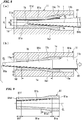
- FIG. 2 shows a schematic cross-sectional view of a variable wall thickness steel pipe 31 manufactured via the steps shown in FIGS. 1(a) to 1(c) .
- the new reference sign 31 is allocated thereto.
- the description will proceed while having new reference signs applied to portions constituting the variable wall thickness steel pipe 31.
- parenthesized reference signs are appended to portions at the point of time of the raw pipe 1. The same also applies to each of the embodiments to be described below.
- the variable wall thickness steel pipe 31 shown in FIG. 2 is configured to include a diameter-increasing portion 31c (1c) which is located on one end portion 31a (1a) side and is increased in diameter from the raw pipe 1, a middle portion 31e (1e) which is located between the one end portion 31a and the other end portion 31d (1d) and is subjected to ironing, and an unprocessed portion 31f which is located on the other end portion 31d side of the middle portion 31e and remains unprocessed as the raw pipe 1.
- the middle portion 31e also includes a part subjected to working by the tapered portions 11c and 21c of the die 11 and the plug 21 at each of boundaries with respect to the diameter-increasing portion 31c and the unprocessed portion 31f.
- the middle portion 31e includes a lock portion 31e1 (1e1) having a constant inner diameter and a tapered outer diameter, a straight pipe portion 31e2 having an inner diameter and an outer diameter both of which are constant, and a tapered portion 31e3 having a constant outer diameter and a tapered inner diameter.
- the average value of hardness of the diameter-increasing portion 31c is H1
- the average value of hardness of the unprocessed portion 31f is H3
- the average value of hardness of the lock portion 31e1 is H4
- the average value of hardness of the straight pipe portion 31e2 is H5
- the average value of hardness of the tapered portion 31e3 is H6, both expressions H5>H6 ⁇ H3 and H5>H4>H1 are satisfied.
- the diameter-increasing portion 31c is shown to have a short ring shape. However, as necessary, the diameter-increasing portion 31c may have a long straight pipe shape. The same applies to each of a diameter-increasing portion 41c, a diameter-increasing portion 61c, a diameter-increasing portion 91c, diameter-increasing portions 111c and 111f, a diameter-increasing portion 121c, a diameter-increasing portion 141c, and a diameter-increasing portion 151c in other embodiments to be described below.
- a hollow portion 31b of the variable wall thickness steel pipe 31 is further increased in diameter than the original inner diameter d 2 of the raw pipe 1.
- the original inner diameter d 2 of the raw pipe 1 remains unchanged.
- the outer diameter of the variable wall thickness steel pipe 31 is gradually increased from the outer diameter d 1 of the raw pipe 1 in the lock portion 31e1. Then, in the diameter-increasing portion 31c, the outer diameter thereof is constant while being further increased than the outer diameter d 1 of the raw pipe 1.
- variable wall thickness steel pipe 31 has a comparatively great thickness in the diameter-increasing portion 31c and the unprocessed portion 31f and has a comparatively small thickness in the middle portion 31e.
- variable wall thickness steel pipe 31 shown in FIG. 2 , since a small working amount is applied to the diameter-increasing portion 31c and the unprocessed portion 31f, no work hardening has occurred in these parts, or even if work hardening has occurred, it is very insignificant. Therefore, the diameter-increasing portion 31c and the unprocessed portion 31f have comparatively low strength. Accordingly, even in a case where post-working such as bending is performed with respect to these parts, annealing treatment or the like for softening work hardening becomes unnecessary.
- the middle portion 31e since a large working amount is applied to the middle portion 31e of the variable wall thickness steel pipe 31, the middle portion 31e has comparatively high strength due to work hardening. That is, as seen in a hardness distribution (Vickers hardness distribution, determination can also be made through a tensile strength distribution instead of Vickers hardness distribution) in the longitudinal direction of the variable wall thickness steel pipe 31, the unprocessed portion 31f has the lowest hardness, and the diameter-increasing portion 31c has hardness slightly higher than hardness of the unprocessed portion 31f. Then, the middle portion 31e has hardness higher than hardness of the diameter-increasing portion 31c.
- the middle portion 31e has the highest hardness, it is preferable to be used for a portion requiring high mechanical strength.
- the unprocessed portion 31f and the diameter-increasing portion 31c having relatively low hardness are preferable to be used as portions requiring post-working such as bending.
- the inner surface of the middle portion 31e has small surface roughness by being subjected to ironing. If the surface roughness is reduced, fatigue properties increase. Accordingly, in addition to improvement of strength due to work hardening, the middle portion 31e can also achieve improvement of fatigue properties due to the reduced surface roughness on the inner surface, thereby realizing weight reduction and high strength. Such a synergistic effect cannot be achieved in thining through simple cutting.
- FIG. 3 shows another example of a variable wall thickness steel pipe manufactured via the steps shown in FIGS. 1(a) to 1(c) .
- a variable wall thickness steel pipe 41 shown in FIG. 3 is a variable wall thickness steel pipe manufactured by thrusting the plug 21 until the large-diameter base end portion 21b of the plug 21 reaches the other end portion 1d of the raw pipe 1, in the step shown in FIG. 1(c) .
- the variable wall thickness steel pipe 41 shown in FIG. 3 is configured to include the diameter-increasing portion 41c (1c) which is located on one end portion 41a side and is increased in diameter from the raw pipe 1, a middle portion 41e (1e) which is located between the one end portion 41a (1a) and the other end portion 41d (1d) and is subjected to ironing, and the other end part 41f which is located on the other end portion 41d side of the middle portion 41e and is subjected to ironing, similar to the middle portion 41e.
- the middle portion 41e also includes a part subjected to working by the tapered portion 11c of the die 11 and the tapered portion 21c of the plug 21 at a boundary with respect to the diameter-increasing portion 41c. That is, the middle portion 41e includes a lock portion 41e1 (1e1). Since the lock portion 41e1 has the same shape as the lock portion 31e1, a duplicate description thereof will be omitted herein.
- variable wall thickness steel pipe 41 In a hollow portion 41b of the variable wall thickness steel pipe 41, the entire inner diameter in its longitudinal direction is further increased than the inner diameter d 2 of the raw pipe 1.
- the outer diameter of the variable wall thickness steel pipe 41 is gradually increased from the outer diameter d 1 of the raw pipe 1 in the lock portion 41e1.
- the diameter-increasing portion 41c the outer diameter thereof is constant while being further increased than the outer diameter d 1 of the raw pipe 1.
- a part excluding the lock portion 41e1 in the middle portion 41e, and the other end part 41f remain having an outer diameter equal to the outer diameter d 1 of the raw pipe 1.
- variable wall thickness steel pipe 41 has a comparatively great thickness in the lock portion 41e1 and the diameter-increasing portion 41c and has a comparatively small thickness in a part excluding the lock portion 41e1 in the middle portion 41e, and the other end part 41f.
- variable wall thickness steel pipe 41 shown in FIG. 3 since a small working amount is applied to the diameter-increasing portion 41c, no work hardening has occurred in this part, or even if work hardening has occurred, it is very insignificant. Therefore, the diameter-increasing portion 41c has comparatively low strength. Accordingly, even in a case where post-working such as bending is performed with respect to this part, annealing treatment or the like for softening work hardening becomes unnecessary.
- the middle portion 41e and the other end part 41f of the variable wall thickness steel pipe 41 since a large working amount is applied to the middle portion 41e and the other end part 41f of the variable wall thickness steel pipe 41, the middle portion 41e and the other end part 41f have comparatively high strength due to work hardening.
- the lock portion lei and the diameter-increasing portion 1c are provided by performing pipe expanding with respect to the one end portion 1a of the raw pipe 1, and ironing is performed with respect to the middle portion 1e on the other end portion 1d side of the diameter-increasing portion 1c of the raw pipe 1 such that the inner diameter is increased while the outer diameter of the raw pipe 1 is maintained, by further thrusting the plug 21 into the raw pipe 1 while the lock portion 1e1 is locked inside the die 11. Therefore, the working amount with respect to the diameter-increasing portion 1c can be reduced, so that heat treatment such as annealing can be made unnecessary when post-working such as bending is performed with respect to the diameter-increasing portion 1c.
- ironing since ironing is performed by thrusting the plug 21 into the raw pipe 1 while the diameter-increasing portion 1c is locked in the die 11, ironing can be carried out by only relatively moving the die 11 and the plug 21 without requiring labor and tools for fixing the raw pipe 1 itself.
- the working amount with respect to a part on the other end portion 1d side becomes zero, so that heat treatment such as annealing can be made unnecessary when post-working such as bending is performed with respect to the unprocessed portion 31f.
- variable wall thickness steel pipe 31 manufactured by the method described above, since the diameter-increasing portion 31c and the unprocessed portion 31f have a small working amount, the thickness is large and strength is comparatively low. Meanwhile, in the middle portion 31e, since the working amount thereof is large, the thickness is small and strength is comparatively high. Therefore, the diameter-increasing portion 31c and the unprocessed portion 31f are in a state where deformability remains, compared to the middle portion 31e, and these parts form the variable wall thickness steel pipe 31 having excellent post-workability such as bending. In addition, since the middle portion 31e has small inner surface roughness by being subjected to ironing, this part forms the variable wall thickness steel pipe 31 having excellent fatigue properties.
- a method of manufacturing a variable wall thickness steel pipe of a second embodiment is configured to include a step of forming a diameter-increasing portion by performing pipe expanding with respect to a part on one end side of a raw pipe using a die and a plug, and a step of ironing a middle portion on the other end side of the diameter-increasing portion such that the inner diameter of the raw pipe is increased while the outer diameter is maintained after the plug is replaced with another plug.
- a raw pipe as a working target of the present embodiment may be similar to that of the first embodiment.
- a die and a plug similar to those of the first embodiment are used in the step of forming the diameter-increasing portion, which is performed first.
- the raw pipe 1 is inserted into the die 11, and positional alignment is performed such that the one end portion 1a of the raw pipe 1 is positioned inside the hollow large-diameter portion 11b of the die 11.
- Each of the die 11 and the raw pipe 1 are in a fixed state.
- the small-diameter tip end portion 21a of the plug 21 is inserted into the hollow portion 1b of the raw pipe 1 from the one end portion 1a side of the raw pipe 1.
- the tapered portion 21c and the large-diameter base end portion 21b of the plug 21 are thrust into the one end portion 1a of the raw pipe 1.
- the plug 21 is thrust until the tapered portion 21c reaches the position of the tapered portion 11c of the die 11. Accordingly, similar to the first embodiment, the lock portion 1e1 and the diameter-increasing portion 1c are formed in the one end portion 1a of the raw pipe 1.
- the thrust plug 21 is pulled out from the raw pipe 1 to be replaced with another plug. Meanwhile, the die 11 is continuously used to the end without being replaced.
- the different plug 51 includes a small-diameter tip end portion 51a corresponding to the inner diameter d 2 of the raw pipe 1, an intermediate-diameter portion 51b having a diameter larger than the inner diameter d 2 of the raw pipe 1 or the outer diameter of the small-diameter tip end portion 51a, a large-diameter base end portion 51c having a diameter larger than the diameter of the intermediate-diameter portion 51b, a first tapered portion 51d being provided between the small-diameter tip end portion 51a and the intermediate-diameter portion 51b, and a second tapered portion 51e being provided between the intermediate-diameter portion 51b and the large-diameter base end portion 51c.
- the diameter of the large-diameter base end portion 51c is set to have a size smaller than the inner diameter d 1 of the hollow small-diameter portion 11a of the die 11.
- the diameter of the small-diameter tip end portion 51a of the plug 51 has the same size as the diameter of the small-diameter tip end portion 21a of the plug 21 used previously.
- the plug 51 is thrust from the one end portion 1a of the raw pipe 1 toward the other end portion 1d.
- the plug 51 is thrust, the raw pipe 1 is pushed from the one end portion 1a toward the other end portion 1 d side.
- the lock portion 1e1 formed in the raw pipe 1 in the previous step remains locked in the tapered portion 11c of the die 11, the raw pipe 1 does not move.
- the plug 51 is thrust until the tip end of the small-diameter tip end portion 51a protrudes from the other end portion 1d of the raw pipe 1.
- the intermediate-diameter portion 51b and the large-diameter base end portion 51c of the plug 51 are thrust into the middle portion 1e of the raw pipe 1.
- the original inner diameter d 2 of the raw pipe 1 is increased to a size corresponding to the diameters of the intermediate-diameter portion 51b and the large-diameter base end portion 51c of the plug 51.
- the middle portion 1e of the raw pipe 1 is positioned inside the hollow small-diameter portion 11a of the die 11, the outer diameter d 1 of the middle portion 1e is not increased. Therefore, the middle portion 1e of the raw pipe 1 is subjected to ironing while the original outer diameter d 1 of the raw pipe 1 is maintained, excluding a part of the lock portion 1e1.
- a part on the other end portion 1d side of the middle portion 1e of the raw pipe 1 is only a part into which the small-diameter tip end portion 51a is inserted, so that the part remains unprocessed.
- FIG. 6 shows a schematic cross-sectional view of a variable wall thickness steel pipe 61 manufactured via the steps shown in FIGS. 4(a) to 5(b) .
- the variable wall thickness steel pipe 61 shown in FIG. 6 is configured to include the diameter-increasing portion 61c (1c) which is located on one end portion 61a side and is increased in diameter from the raw pipe 1, a middle portion 61e (1e) which is located between the one end portion 61a (1a) and the other end portion 61d (1d) and is subjected to ironing, and an unprocessed portion 61f which is located on the other end portion 61d side of the middle portion 61e and remains unprocessed as the raw pipe 1.
- the middle portion 61e also includes a part subjected to working by the tapered portion 11c of the die 11 and the tapered portions 51d and 51e of the plug 51 at each of boundaries with respect to the diameter-increasing portion 61c and the unprocessed portion 61f. That is, the middle portion 61e includes a lock portion 61e1 (1e1). Since the lock portion 61e1 has the same shape as the lock portion 31e1, a duplicate description thereof will be omitted herein.
- the inner diameter of a hollow portion 61b of the variable wall thickness steel pipe 61 is further increased than the inner diameter d 2 of the raw pipe 1. Then, in the unprocessed portion 61f, the inner diameter of a hollow portion 61b of the variable wall thickness steel pipe 61 remains the inner diameter d 2 of the raw pipe 1.
- the inner diameter of a part on the one end portion 61a side is increased by the large-diameter base end portion 51c of the plug 51, and the inner diameter of a part on the other end portion 61d side is increased by the intermediate-diameter portion 51b of the plug 51.
- variable wall thickness steel pipe 61 has a comparatively great thickness in the diameter-increasing portion 61c and the unprocessed portion 61f and has a comparatively small thickness in the middle portion 61e.
- variable wall thickness steel pipe 61 shown in FIG. 6 , since a small working amount is applied to the diameter-increasing portion 61c and the unprocessed portion 61f, no work hardening has occurred in these parts, or even if work hardening has occurred, it is very insignificant. Therefore, the diameter-increasing portion 61c or the unprocessed portion 61f has comparatively low strength. Accordingly, even in a case where post-working such as bending is performed with respect to these parts, annealing treatment or the like for softening work hardening becomes unnecessary.
- the middle portion 61e of the variable wall thickness steel pipe 61 since a comparatively large working amount is applied to the middle portion 61e of the variable wall thickness steel pipe 61, the middle portion 61e has comparatively high strength due to work hardening.
- ironing is performed with respect to the middle portion 1e of the raw pipe 1 using the plug 51.
- the diameter-increasing amount of a region on the diameter-increasing portion 1c side is larger than the diameter-increasing amount of a region on the other end portion 1d side, so that two regions of which the inner diameters and strengths are different from each other can be provided inside the middle portion 1e.
- variable wall thickness steel pipe 61 manufactured by the method described above has the middle portion 61e in which the diameter-increasing amount of a region on the diameter-increasing portion 61c side is larger than the diameter-increasing amount of a region on the other end portion 61d side, and the working amount of a region on the diameter-increasing portion 61c side is larger than the working amount of a region on the other end portion 61d side. Therefore, the variable wall thickness steel pipe 61 has regions of which the thicknesses and strength are different from each other in the middle portion 61e.
- a method of manufacturing a variable wall thickness steel pipe of a third embodiment will be described with reference to FIGS. 7(a) to 7(c) .
- the method of manufacturing a variable wall thickness steel pipe of the present embodiment is configured to include a step similar to that of the first embodiment.
- the variable wall thickness steel pipe is manufactured by using a plug 71 which is different from the plug 21 used in the first embodiment. Since other configurations are similar to those of the first embodiment, a description will be omitted.
- the plug 71 used in the present embodiment is configured to include a tapered tip end portion 71c having a tip end portion 71a smaller than the inner diameter d 2 of the raw pipe 1, and a base end portion 71b having a diameter larger than the inner diameter d 2 of the raw pipe 1.
- the diameter of the base end portion 71b is set to have a size smaller than the inner diameter d 1 of the hollow small-diameter portion 11a of the die 11.
- the tapered tip end portion 71c and the base end portion 71b of the plug 71 are thrust into the one end portion 1a of the raw pipe 1.
- the plug 71 is thrust until the tapered tip end portion 71c reaches the position of the tapered portion 11c of the die 11. Accordingly, the lock portion 1e1 and the diameter-increasing portion 1c are formed in the one end portion 1a of the raw pipe 1.
- the plug 71 is further thrust toward the other end portion 1d side of the raw pipe 1.
- the raw pipe 1 is pushed from the one end portion 1a toward the other end portion 1d side.
- the lock portion lei formed in the raw pipe 1 in the previous step remains locked in the tapered portion 11c of the die 11, the raw pipe 1 does not move.
- the plug 71 in the present embodiment is configured to include the tapered tip end portion 71c and the base end portion 71b and does not include the small-diameter tip end portion 21a shown in the first embodiment, its length in the longitudinal direction is comparatively short. Therefore, compared to the first embodiment, the required stroke amount of the plug 71 when inserting the plug 71 into the raw pipe 1 or when pulling out the plug 71 from the raw pipe 1 becomes short. As a result, the work hour for taking out and putting in the plug 71 can be shortened, and a hydraulic cylinder (not shown) having a simple structure for taking out and putting in the plug 71 can be employed. Therefore, it is possible to perform working even with comparatively small manufacturing equipment.
- variable wall thickness steel pipe which has been manufactured via the steps shown in FIGS. 7(a) to 7(c) has a shape similar to that of the variable wall thickness steel pipe 31 shown in FIG. 2 .
- the variable wall thickness steel pipe may be worked into a shape similar to the variable wall thickness steel pipe 41 as shown in FIG. 3 by thrusting the plug 71 until the base end portion 71b of the plug 71 reaches the other end portion 1d of the raw pipe 1.
- variable wall thickness steel pipe is manufactured by using the plug 71 having a comparatively short length in the longitudinal direction, compared to the first embodiment, it is possible to comparatively reduce the required stroke amount of the plug 71 at the time of manufacturing.
- the method of manufacturing a variable wall thickness steel pipe of the present embodiment is configured to include a step similar to that of the second embodiment.
- ironing is performed by using a plug 81 different from the plug 51 used in the ironing step of the second embodiment. Since other configurations are similar to those of the second embodiment, a description will be omitted.
- the lock portion 1e1 and the diameter-increasing portion 1c are formed in the raw pipe 1.
- the plug 81 is configured to include a tapered tip end portion 81c having a tip end portion 81a smaller than the inner diameter d 2 of the raw pipe 1, and a base end portion 81b having a diameter larger than the inner diameter d 2 of the raw pipe 1 and a diameter smaller than the inner diameter d 1 of the hollow small-diameter portion 11a of the die 11.
- the tapered tip end portion 81c of the plug 81 is longer than the length of the tapered tip end portion 71c of the plug 71 shown in FIG. 7(a) .
- the plug 81 is thrust from the one end portion 1a of the raw pipe 1 toward the other end portion 1d.
- the plug 81 is thrust, the raw pipe 1 is pushed from the one end portion 1a toward the other end portion 1d side.
- the lock portion 1e1 formed in the raw pipe 1 in the previous step remains locked in the tapered portion 11c of the die 11, the raw pipe 1 does not move.
- the plug 81 is thrust until the tip end portion 81a of the plug 81 protrudes from the other end portion 1d of the raw pipe 1.
- the tapered tip end portion 81c of the plug 81 is thrust into the middle portion 1e of the raw pipe 1.
- the original inner diameter d 2 of the raw pipe 1 is increased to a size corresponding to the diameter of the tapered tip end portion 81c of the plug 81.
- the plug 81 used in the present embodiment includes the tapered tip end portion 81c having a comparatively long taper length, the inner diameter of the middle portion 1e of the raw pipe 1 becomes the same as the outer diameter of the tapered tip end portion 81c of the plug 81 over the entire length. That is, the inner diameter of the middle portion 1e of the raw pipe 1 is gradually increased from the other end portion 1d side to the one end portion 1a side.
- FIG. 9 shows a schematic cross-sectional view of the variable wall thickness steel pipe manufactured in accordance with the present embodiment.
- a variable wall thickness steel pipe 91 shown in FIG. 9 is configured to include a diameter-increasing portion 91c (1c) which is located on one end portion 91a (1a) side and is increased in diameter from the raw pipe 1, a middle portion 91e (1e) which is located between the one end portion 91a and the other end portion 91d (1d) and is subjected to ironing, and an unprocessed portion 91f which is located on the other end portion 91d side of the middle portion 91e and remains unprocessed as the raw pipe 1.
- a diameter-increasing portion 91c (1c) which is located on one end portion 91a (1a) side and is increased in diameter from the raw pipe 1
- a middle portion 91e (1e) which is located between the one end portion 91a and the other end portion 91d (1d) and is subjected to ironing
- the inner diameter of a hollow portion 91b of the variable wall thickness steel pipe 91 is further increased than the inner diameter d 2 of the raw pipe 1.
- the inner diameter d 2 of the raw pipe remains unchanged.
- the outer diameter of the variable wall thickness steel pipe 91 is further increased than the outer diameter d 1 of the raw pipe 1. A part excluding the lock portion 91e1 in the middle portion 91e, and the unprocessed portion 91f remain unchanged as the outer diameter d 1 of the raw pipe 1.
- the inner diameter in the middle portion 91e gradually increases from the other end portion 1d side to the one end portion 1a side. Accordingly, the diameter-increasing portion 91c and the unprocessed portion 91f have a comparatively great thickness. In addition, in a case where the thickness of the middle portion 91e is seen from the diameter-increasing portion 91c toward the unprocessed portion 91f, the thickness is gradually reduced in the lock portion 91e1 and gradually increases in parts other than the lock portion 91e1.
- variable wall thickness steel pipe 91 shown in FIG. 9 , since a small working amount is applied to the diameter-increasing portion 91c and the unprocessed portion 91f, no work hardening has occurred in these parts, or even if work hardening has occurred, it is very insignificant.
- ironing is performed with respect to the middle portion 1e of the raw pipe 1 by using the plug 81 having the tapered tip end portion 81c which is comparatively long. Therefore, it is possible to manufacture the variable wall thickness steel pipe in which the inner diameter is gradually reduced from the diameter-increasing portion 1c side to the other end portion 1 d side in the middle portion 1e.
- a method of manufacturing a variable wall thickness steel pipe of a fifth embodiment is configured to include a step of forming diameter-increasing portions 1c and 1f by performing pipe expanding with respect to both end parts of the raw pipe 1 using one die and two plugs; a step of performing first ironing in which a plug 22 on the other end side is pulled while the plug 21 on one end side is inserted in the raw pipe 1, and the inner diameter of a middle portion 1g on the other end side of the diameter-increasing portion 1c on one end side is increased while the outer diameter of the raw pipe 1 is maintained; and a step of performing second ironing in which the plug 21 on one end side is pulled from the raw pipe 1, the plug 22 on the other end side is inserted into the raw pipe 1, and the inner diameter of a middle portion 1h on one end side of the diameter-increasing portion 1f on the other end side is increased while the outer diameter of the raw pipe 1 is maintained.
- the raw pipe 1 as a working target of the present embodiment may be similar to that of the
- a die 12 shown in FIG. 10(a) is used.
- the die 12 is configured to include a hollow small-diameter portion 12b having an inner diameter corresponding to the outer diameter d 1 of the raw pipe 1, and a hollow large-diameter portion 12a and a hollow large-diameter portion 12d being provided on both sides of the hollow small-diameter portion 12b in the longitudinal direction and having an inner diameter larger than the outer diameter d 1 of the raw pipe 1.
- a tapered portion 12c is provided between the hollow small-diameter portion 12b and the hollow large-diameter portion 12a
- a tapered portion 12e is provided between the hollow small-diameter portion 12b and the hollow large-diameter portion 12d.
- the hollow large-diameter portion 12a, the tapered portion 12c, the hollow small-diameter portion 12b, the tapered portion 12e, and the hollow large-diameter portion 12d communicate with each other inside a die main body 12f.
- the die 12 has a two-division structure which can be divided in an upward/downward direction in FIG. 10(a) .
- the one-dot chained lines vertically shown in FIGS. 10(a) to 10(d) are center lines indicating half the length of the die 12 in the longitudinal direction, and the die 12 has a line symmetric shape having this one-dot chained line as a symmetric axis.
- the plug 22 has a shape similar to the plug 21 and is configured to include a small-diameter tip end portion 22a corresponding to the inner diameter d 2 of the raw pipe 1, a large-diameter base end portion 22b having a diameter larger than the inner diameter d 2 of the raw pipe 1, and a tapered portion 22c being provided between the small-diameter tip end portion 22a and the large-diameter base end portion 22b.
- the diameter of the large-diameter base end portion 22b is set to have a size smaller than the inner diameter d 1 of the hollow small-diameter portion 12b of the die 12.
- the raw pipe 1 is inserted into the die 12. At this time, positional alignment is performed such that the one end portion 1a and the other end portion 1d of the raw pipe 1 are respectively positioned in the hollow large-diameter portions 12a and 12d of the die 12. Then, the small-diameter tip end portion 21a of the plug 21 and the small-diameter tip end portion 22a of the plug 22 are inserted into the hollow portion 1b of the raw pipe 1 from the one end portion 1a side and the other end portion 1d side of the raw pipe 1, respectively. At this time, the raw pipe 1 and the die 12 are in a non-fixed state.
- the tapered portion 21c and the large-diameter base end portion 21b of the plug 21 are thrust into the one end portion 1a of the raw pipe 1, and the tapered portion 22c and the large-diameter base end portion 22b of the plug 22 are thrust into the other end portion 1d of the raw pipe 1, simultaneously.
- the plug 21 is thrust until the tapered portion 21c reaches the position of the tapered portion 12c of the die 12, and the plug 22 is thrust until the tapered portion 22c reaches the position of the tapered portion 12e of the die 12.
- a lock portion 1g1 and the diameter-increasing portion 1c are formed on the one end portion 1a side of the raw pipe 1.
- a lock portion 1h1 and the diameter-increasing portion 1f are formed on the other end portion 1d side.
- the plug 21 on the one end portion 1a side remains unchanged, the plug 22 on the other end portion 1d side is pulled out from the raw pipe 1.
- the plug 21 is further thrust toward the other end portion 1d side of the raw pipe 1.
- the raw pipe 1 is pushed from the one end portion 1a toward the other end portion 1d side.
- the lock portion 1g1 formed in the raw pipe 1 in the previous step remains locked in the tapered portion 12c of the die 12, the raw pipe 1 does not move.
- the tapered portion 21c and the large-diameter base end portion 21b of the plug 21 are thrust to the position on the one end portion 12h side of a middle position of the die 12. If thrusting of the plug 21 stops at the position as shown in FIG. 10(c) , a part between the diameter-increasing portion 1f of the raw pipe 1 on the other end portion 1d side and a first working part 1g of the raw pipe 1 subjected to ironing remains unprocessed.
- the plug 21 pulled out from the raw pipe 1, and the plug 22 is inserted into the raw pipe 1 on the other end portion 1d side.
- the plug 22 is further thrust toward the one end portion 1a side of the raw pipe 1.
- the raw pipe 1 is in a non-fixed state, whereas the one end portion 12h side of the die is fixed.
- the plug 22 is further thrust, the raw pipe 1 is pushed from the other end portion 1d side toward the one end portion 1a side.
- the lock portion 1h1 formed in the raw pipe 1 in advance in the diameter-increasing step is locked in the tapered portion 12e of the die 12, the raw pipe 1 does not move.
- the tapered portion 22c and the large-diameter base end portion 22b of the plug 22 are thrust to the position on the other end portion 12g side of the middle of the die 12. If thrusting of the plug 22 stops at the position as shown in FIG. 10(d) , a middle portion 1i between the first working part 1g and a second working part 1h of the raw pipe 1 remains unprocessed.
- FIG. 11 shows a schematic cross-sectional view of a variable wall thickness steel pipe 111 manufactured via the steps shown in FIGS. 10(a) to 10(d) .
- the variable wall thickness steel pipe 111 is configured to include the diameter-increasing portion 111c (1c) which is located on one end portion 111a (1a) side and is increased in diameter from the raw pipe 1, a first working part 111g (1g) which is located between the one end portion 111a and the other end portion 111d (1d) and is subjected to first ironing, the diameter-increasing portion 111f (1f) which is located on the other end portion 111d side and is increased in diameter from the raw pipe 1, a second working part 111h (1h) which is located between the other end portion 111d and the one end portion 111a and is subjected to second ironing, and an unprocessed portion 111i (1i) which is located between the first working part 111g and the second working part 111h and remains unprocessed as
- the first working part 111g also includes parts subjected to working by the tapered portions 12c and 21c of the die 12 and the plug 21 at each of boundaries with respect to the diameter-increasing portion 111c and the unprocessed portion 111i. That is, the first working part 111g includes a lock portion 111g1 (1g1) leading to the diameter-increasing portion 111c, and a tapered portion 111g2 leading to the unprocessed portion 111i.
- the second working part 111h also includes parts subjected to working by the tapered portions 12c and 22c of the die 12 and the plug 22 at each of boundaries with respect to the diameter-increasing portion 111f and the unprocessed portion 111i. That is, the second working part 111h includes a lock portion 111h1 (1h1) leading to the diameter-increasing portion 111f, and a tapered portion 111h2 leading to the unprocessed portion 111i.
- a hollow portion 111b of the variable wall thickness steel pipe 111 is further increased in diameter than the original inner diameter d 2 of the raw pipe 1 in the diameter-increasing portion 111c, the first working part 111g, the diameter-increasing portion 111f, and the second working part 111h. Meanwhile, in the unprocessed portion 111i, the original inner diameter d 2 of the raw pipe 1 remains unchanged.
- the outer diameter of the variable wall thickness steel pipe 111 is further increased than the outer diameter d 1 of the raw pipe 1 in the diameter-increasing portion 111c, a lock portion 111g1, the diameter-increasing portion 111f, and the lock portion 111h1.
- a part excluding the lock portion 111g1 in the first working part 111g, a part excluding the lock portion 111h1 in the second working part 111h, and the unprocessed portion 111i remain unchanged as the outer diameter d 1 of the raw pipe 1.
- variable wall thickness steel pipe has a comparatively great thickness in the diameter-increasing portion 111c, the diameter-increasing portion 111f, and the unprocessed portion 111i and has a comparatively small thickness in the first working part 111g and the second working part 111h.
- variable wall thickness steel pipe 111 shown in FIG. 11 since a small working amount is applied to the diameter-increasing portion 111c, the diameter-increasing portion 111f, and the unprocessed portion 111i, no work hardening has occurred in these parts, or even if work hardening has occurred, it is very insignificant. Therefore, the diameter-increasing portion 111c, the diameter-increasing portion 111f, and the unprocessed portion 111i have comparatively low strength. Accordingly, even in a case where post-working such as bending is performed with respect to these parts, annealing treatment or the like for softening work hardening becomes unnecessary.
- the first working part 111g and the second working part 111h have comparatively high strength due to work hardening.
- FIG. 12 shows another example of a variable wall thickness steel pipe manufactured via the steps shown in FIGS. 10(a) to 10(d) .
- a variable wall thickness steel pipe 121 shown in FIG. 12 is a variable wall thickness steel pipe manufactured by thrusting the plug 22 until the large-diameter base end portion 22b of the plug 22 reaches the one end portion 1a of the raw pipe 1, in the step shown in FIG. 10(d) .
- the variable wall thickness steel pipe 121 shown in FIG. 12 is configured to include a diameter-increasing portion 121c (1c) which is located on one end portion 121a side and is increased in diameter from the raw pipe 1, a diameter-increasing portion 121f (1c) which is located on the other end portion 121d (1d) side and is increased in diameter from the raw pipe 1, and a middle portion 121e (1e) which is located between the one end portion 121a and the other end portion 121d and is subjected to ironing.
- a diameter-increasing portion 121c (1c) which is located on one end portion 121a side and is increased in diameter from the raw pipe 1
- a diameter-increasing portion 121f (1c) which is located on the other end portion 121d (1d) side and is increased in diameter from the raw pipe 1
- a middle portion 121e (1e) which is located between the one end portion 121a and the other end portion 121d and is subjected to iron
- the middle portion 121e also includes a part subjected to working by the tapered portion 12c of the die 12 and the tapered portion 21c of the plug 21 at a boundary with respect to the diameter-increasing portion 121c, and a part subjected to working by the tapered portion 12e of the die 12 and the tapered portion 22c of the plug 22 at a boundary with respect to the diameter-increasing portion 121f. That is, the middle portion 121e includes a lock portion 121e1 (1g1) leading to the diameter-increasing portion 121c, and a lock portion 121e2 (1h1) leading to the diameter-increasing portion 121f.
- variable wall thickness steel pipe 121 In a hollow portion 121b of the variable wall thickness steel pipe 121, the entire inner diameter in its longitudinal direction is further increased than the inner diameter d 2 of the raw pipe 1.
- the outer diameter of the variable wall thickness steel pipe 121 is further increased than the outer diameter d 1 of the raw pipe 1 in the diameter-increasing portion 121c, lock portions 121e1 and 121e2 located at both ends of the middle portion 121e, and the diameter-increasing portion 121f.
- a part excluding the lock portions 121e1 and 121e2 from the middle portion 121e remains unchanged as the outer diameter d 1 of the raw pipe 1. Accordingly, the variable wall thickness steel pipe 121 has a comparatively great thickness in the diameter-increasing portion 121c and the diameter-increasing portion 121f and has a comparatively small thickness in the middle portion 41e.
- variable wall thickness steel pipe 121 shown in FIG. 12 , since a small working amount is applied to the diameter-increasing portion 121c and the diameter-increasing portion 121f, no work hardening has occurred in these part, or even if work hardening has occurred, it is very insignificant. Therefore, even in a case where post-working such as bending is performed with respect to the diameter-increasing portion 121c or the diameter-increasing portion 121f, annealing treatment or the like for softening work hardening becomes unnecessary.
- the middle portion 121e since a comparatively large working amount is applied to the middle portion 121e, the middle portion 121e has comparatively high strength due to work hardening.
- the variable wall thickness steel pipe 111 is manufactured by using one die 12 and two plugs 21 and 22. Therefore, the diameter-increasing portion 1c (121c) and the diameter-increasing portion 1f (121f) can be respectively provided on the one end portion 1a side and the other end portion 1d side of the raw pipe 1. In addition, a region which remains unprocessed as the raw pipe 1 and regions subjected to ironing on both sides in the longitudinal direction can be provided in a region between the diameter-increasing portion 1c and the diameter-increasing portion 1f of the raw pipe 1, so that it is possible to manufacture a variable wall thickness steel pipe in which the thickness varies in stages.
- variable wall thickness steel pipe 111 is manufactured by using the die 12 in a line symmetric shape having the one-dot chained line in FIGS. 10(a) to 10(d) as a symmetric axis.
- the die 12 may have a non-line symmetric shape, and the variable wall thickness steel pipe 111 may be manufactured by using two plugs of which the shapes are different from each other.
- variable wall thickness steel pipe of a sixth embodiment a method of manufacturing a variable wall thickness steel pipe of a sixth embodiment will be described with reference to FIGS. 13(a) to 13(c) .
- the method of manufacturing a variable wall thickness steel pipe of the present embodiment is configured to include a step similar to that of the first embodiment.
- the variable wall thickness steel pipe is manufactured by using a die 13 which is different from the die 11 used in the first embodiment. Since other configurations are similar to those of the first embodiment, a description will be omitted.
- the die 13 used in the present embodiment is configured to include a first hollow small-diameter portion 13a and a second hollow small-diameter portion 13b having an inner diameter corresponding to the outer diameter d 1 of the raw pipe 1, a thickly-formed portion 13e being provided between the first hollow small-diameter portion 13a and the second hollow small-diameter portion 13b, a hollow large-diameter portion 13d having an inner diameter d 3 larger than the outer diameter d 1 of the raw pipe 1, and a tapered portion 13c being provided between the first hollow small-diameter portion 13a and the hollow large-diameter portion 13d.
- the hollow large-diameter portion 13d, the tapered portion 13c, the first hollow small-diameter portion 13a, the thickly-formed portion 13e, and the second hollow small-diameter portion 13b communicate with each other inside a die main body 13i.
- the die 13 can be divided in the upward/downward direction on the sheet in FIG. 13(a) .
- the thickly-formed portion 13e is configured to include a hollow intermediate-diameter portion 13f, a tapered portion 13h being provided between the hollow intermediate-diameter portion 13f and the first hollow small-diameter portion 13a, and a tapered portion 13g being provided between the hollow intermediate-diameter portion 13f and the second hollow small-diameter portion 13b.
- the inner diameter d 3 of the hollow intermediate-diameter portion 13f is set to be an inner diameter larger than the outer diameter d 1 of the raw pipe 1 and to be an inner diameter smaller than the inner diameter of the hollow large-diameter portion 13d.
- the raw pipe 1 is only subjected to pipe expanding in the hollow intermediate-diameter portion 13f during the ironing step without being subjected to thinning. Therefore, the thickness of the raw pipe 1 in the thickly-formed portion 13e remains unchanged as the original thickness of the raw pipe 1.
- the diameter-increasing step is performed. First, while the end portions of the die 13 and the raw pipe 1 on the sheet left side are in a fixed state, the small-diameter tip end portion 21a and the large-diameter base end portion 21b of the plug 21 are thrust into the one end portion 1a of the raw pipe 1. The plug 21 is thrust until the tapered portion 21c reaches the position of the tapered portion 13c of the die 13. Accordingly, the diameter-increasing portion 1c and the lock portion 1e1 are formed in the one end portion 1a of the raw pipe 1.
- the plug 21 is further thrust toward the other end portion 1d side of the raw pipe 1.
- the raw pipe 1 is pushed from the one end portion 1a toward the other end portion 1d side.
- the lock portion lei formed in the raw pipe 1 in the previous step remains locked in the tapered portion 13c of the die 13, the raw pipe 1 does not move. If the tapered portion 21c and the large-diameter base end portion 21b of the plug 21 are thrust to the position shown in FIG.
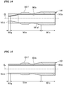
- FIG. 14 shows a schematic cross-sectional view of a variable wall thickness steel pipe 141 manufactured via the steps shown in FIGS. 13(a) to 13(c) .
- the variable wall thickness steel pipe 141 is configured to include a diameter-increasing portion 141c (1c) which is located on one end portion 141a (1a) side and is increased in diameter from the raw pipe 1, a middle portion 141e (1e) which is located between the one end portion 141a and the other end portion 141d (1d) and is subjected to ironing, and an unprocessed portion 141g which is located on the other end portion 141d side of the middle portion 141e and remains unprocessed as the raw pipe 1.
- the middle portion 141e also includes a lock portion 141e1 (1e1) subjected to working by the tapered portion 13c of the die 13 and the tapered portion 21c of the plug 21 at a boundary with respect to the diameter-increasing portion 141c, and a thick portion 141f subjected to working by the thickly-formed portion 13e of the die 13 and the tapered portion 21c of the plug 21.
- a hollow portion 141b of the variable wall thickness steel pipe 141 remains unchanged as the inner diameter d 2 of the raw pipe 1 in the unprocessed portion 141g, whereas a hollow portion 141b of the variable wall thickness steel pipe 141 is further increased in diameter than the inner diameter d 2 of the raw pipe 1 in the diameter-increasing portion 141c and the middle portion 141e.
- the outer diameter of the variable wall thickness steel pipe 141 is further increased than the outer diameter d 1 of the raw pipe 1.
- variable wall thickness steel pipe 141 has a constant inner diameter in the shape-increasing portion 141g and a part of the middle portion 141e excluding a portion thereof. Furthermore, the thick portion 141f and the diameter-increasing portion 141c have outer diameters different from each other.
- variable wall thickness steel pipe 141 shown in FIG. 14 , since a small working amount is applied to the diameter-increasing portion 141c and the unprocessed portion 141g, no work hardening has occurred in these parts, or even if work hardening has occurred, it is very insignificant. Therefore, the diameter-increasing portion 141c and the unprocessed portion 141g have low strength. Accordingly, even in a case where post-working such as bending is performed with respect to these parts, annealing treatment or the like for softening work hardening becomes unnecessary.
- the middle portion 141e of the variable wall thickness steel pipe 141 since a comparatively large working amount is applied to the middle portion 141e of the variable wall thickness steel pipe 141, the middle portion 141e has comparatively high strength due to work hardening.
- FIG. 15 shows another example of a variable wall thickness steel pipe manufactured via the steps shown in FIGS. 13(a) to 13(c) . That is, in this example, in the step shown in FIG. 13(c) , a variable wall thickness steel pipe 151 having a shape as shown in FIG. 15 is worked by thrusting the plug 21 until the large-diameter base end portion 21b of the plug 21 reaches the other end portion 1d of the raw pipe 1.
- the variable wall thickness steel pipe 151 shown in FIG. 15 is configured to include a diameter-increasing portion 151c (1c) which is located on one end portion 151a (1a) side and is increased in diameter from the raw pipe 1, a middle portion 151e (1e) which is located between the one end portion 151a and the other end portion 151d (1d) and is subjected to ironing, and the other end part 151g which is located on the other end portion 151d side of the middle portion 151e and is subjected to ironing, similar to the middle portion 151e.
- a diameter-increasing portion 151c (1c) which is located on one end portion 151a (1a) side and is increased in diameter from the raw pipe 1
- a middle portion 151e (1e) which is located between the one end portion 151a and the other end portion 151d (1d) and is subjected to ironing
- the other end part 151g which is located on the other end portion 151d side of the middle portion 151
- the middle portion 151e includes a part subjected to working by the tapered portion 13c of the die 13 and the tapered portion 21c of the plug 21 at a boundary with respect to the diameter-increasing portion 151c, and a thick portion 151f subjected to working by the thickly-formed portion 13e of the die 13 and the tapered portion 21c of the plug 21.
- variable wall thickness steel pipe 151 In a hollow portion 151b of the variable wall thickness steel pipe 151, the entire inner diameter in its longitudinal direction is further increased than the inner diameter d 2 of the raw pipe 1. In addition, the outer diameter of the variable wall thickness steel pipe 151 is further increased than the outer diameter d 1 of the raw pipe 1 in the diameter-increasing portion 151c and the thick portion 151f. In the middle portion 151e and the other end part 151g other than the thick portion 151f, the outer diameter d 1 of the raw pipe 1 remains unchanged. Therefore, the variable wall thickness steel pipe 151 has an entirely constant inner diameter in the longitudinal direction and has a plurality of parts of which the outer diameters are different from each other.
- variable wall thickness steel pipe 151 shown in FIG. 15 since a small working amount is applied to the diameter-increasing portion 151c, no work hardening has occurred in this part, or even if work hardening has occurred, it is very insignificant. Therefore, the diameter-increasing portion 151c has comparatively low strength. Accordingly, even in a case where post-working such as bending is performed with respect to this part, annealing treatment or the like for softening work hardening becomes unnecessary.
- the middle portion 151e and the other end part 151g of the variable wall thickness steel pipe 151 since a comparatively large working amount is applied to the middle portion 151e and the other end part 151g of the variable wall thickness steel pipe 151, the middle portion 151e and the other end part 151g have comparatively high strength due to work hardening.
- variable wall thickness steel pipe 141 is manufactured by using the die 13 having the thickly-formed portion 13e between the first hollow small-diameter portion 13a and the second hollow small-diameter portion 13b. Therefore, it is possible to manufacture the variable wall thickness steel pipe 141 having the thick portion 1j (141f) in the middle portion 1e of the raw pipe 1 (141e). In addition, it is possible to manufacture the variable wall thickness steel pipe 141 of which outer diameters are different from each other in the thick portion 1j and the diameter-increasing portion 1c (141c).
- variable wall thickness steel pipe 141 since the working amount is comparatively small on the other end portion 1d (141d) side of the diameter-increasing portion 1c and the middle portion 1e, strength is low. Meanwhile, in the middle portion 1e including the thick portion 1j, since the working amount is comparatively large, strength is high.
- variable wall thickness steel pipe of a seventh embodiment a method of manufacturing a variable wall thickness steel pipe of a seventh embodiment will be described with reference to FIGS. 16(a) to 16(c) .
- the method of manufacturing a variable wall thickness steel pipe of the present embodiment is configured to include a step similar to that of the first embodiment.
- the variable wall thickness steel pipe is manufactured by using a plug 161 which is different from the plug 21 used in the first embodiment. Since other configurations are similar to those of the first embodiment, a description will be omitted.
- the plug 161 used in the present embodiment is configured to include a tapered tip end portion 161b having a tip end portion 161a having an outer diameter smaller than the inner diameter d 2 of the raw pipe 1, a large-diameter portion 161c having a diameter d 5 larger than the inner diameter d 2 of the raw pipe 1 and smaller than the inner diameter d 1 of the hollow small-diameter portion 11a of the die 11, and a small-diameter base end portion 161e having a diameter d 4 smaller than the diameter d 5 of the large-diameter portion 161c.
- a tapered portion 161d is provided between the large-diameter portion 161c and the small-diameter base end portion 161e.
- the tapered tip end portion 161b and the large-diameter portion 161c of the plug 161 are thrust into the one end portion 1a of the raw pipe 1.
- the plug 161 is thrust until the tapered tip end portion 161b reaches the position of the tapered portion 11c of the die 11. Accordingly, the diameter-increasing portion 1c and the lock portion 1e1 are formed in the one end portion 1a of the raw pipe 1.
- the plug 161 is further thrust toward the other end portion 1d side of the raw pipe 1.
- the raw pipe 1 is pushed from the one end portion 1a toward the other end portion 1d side.
- the lock portion lei formed in the raw pipe 1 in the previous step remains locked in the tapered portion 11c of the die 11, the raw pipe 1 does not move.
- the original inner diameter d 2 of the raw pipe 1 is increased to a size corresponding to the diameter d 5 of the large-diameter portion 161c of the plug 161.
- the diameter d 4 of the small-diameter base end portion 161e succeeding the large-diameter portion 161c of the plug 161 is smaller than the diameter d 5 of the large-diameter portion 161c, the small-diameter base end portion 161e does not come into contact with a part of the raw pipe 1 subjected to ironing.
- the plug 161 comes into contact with the raw pipe 1 in only the tapered tip end portion 161b and the large-diameter portion 161c. Accordingly, since a part of the plug 161 coming into contact with the raw pipe 1 is smaller than that of the first embodiment, frictional resistance between the raw pipe 1 and the plug 161 is reduced in the ironing step.
- the difference (d 5 -d 4 ) between the diameter d4 of the small-diameter base end portion 161e of the plug 161 in FIG. 16(a) and the diameter d 5 of the large-diameter portion 161c ranges as follows. That is, when the thickness of the raw pipe 1 is do and the thickness of the middle portion 1e after ironing is d, the difference between d 0 and d (d 0 -d) is defined as the amount t d of thickness reduction.
- the amount t d of thickness reduction and the difference (d 5 -d 4 ) between the diameter d4 of the small-diameter base end portion 161e and the diameter d 5 of the large-diameter portion 161c is favorable to be 2 ⁇ t d ⁇ (d 5 -d 4 ).
- the lock portion 1e1 of the raw pipe 1 can no longer be locked in the tapered portion 11c of the die 11 in the ironing step shown in FIG. 16(c) .
- variable wall thickness steel pipe manufactured via the steps shown in FIGS. 16(a) to 16(c) has a shape similar to the variable wall thickness steel pipe 31 shown in FIG. 2 .
- the variable wall thickness steel pipe may be worked into a shape similar to that of the variable wall thickness steel pipe 41 shown in FIG. 3 by thrusting the plug 161 until the large-diameter portion 161c of the plug 161 reaches the other end portion 1d of the raw pipe 1.
- the ironing step can be performed without having the small-diameter base end portion 161e and a part of the raw pipe 1 subjected to ironing coming into contact with each other in the ironing step. That is, when the plug 161 is thrust, only the tapered tip end portion 161b and the large-diameter portion 161c come into slide contact with the inner surface of the raw pipe 1.
- a method of manufacturing a variable wall thickness steel pipe of an eighth embodiment has a step of performing drawing after ironing of the first to fourth embodiments and the sixth and seventh embodiments.
- the variable wall thickness steel pipe 61 manufactured via the step of the second embodiment is taken as an intermediate product 15, and drawing is performed with respect to the intermediate product 15.
- the intermediate product 15 shown in FIG. 17(a) is the variable wall thickness steel pipe 61 manufactured via the step of the second embodiment.
- the intermediate product 15 is configured to include a diameter-increasing portion 15c which is located in one end portion 15a side and is increased in diameter from the raw pipe 1, a middle portion 15e which is located between the one end portion 15a and the other end portion 15d and is subjected to ironing, and an unprocessed portion 15f which is located on the other end portion 15d side of the middle portion 15e and remains unprocessed as the raw pipe 1.
- the middle portion 15e also includes a part subjected to working by the tapered portion 11c of the die 11 used in the second embodiment, and the tapered portions 51d and 51e of the plug 51 at each of boundaries with respect to the diameter-increasing portion 15c and the unprocessed portion 15f.
- the die 14 shown in FIG. 17(a) is configured to include a hollow small-diameter portion 14b having an inner diameter corresponding to the outer diameters of the unprocessed portion 15f and the middle portion 15e of the intermediate product 15, and a tapered portion 14c leading to the hollow small-diameter portion 14b.
- the above-mentioned expression "the inner diameter corresponding to the outer diameters of the unprocessed portion 15f and the middle portion 15e" indicates a diameter size in which a gap size, to the extent that the hollow small-diameter portion 14b can be taken out and put in with respect to the inside and the outside, is added to the outer diameters of the unprocessed portion 15f and the middle portion 15e.
- the hollow small-diameter portion 14b and the tapered portion 14c communicate with each other inside a die main body 14e.
- the inner diameter of the hollow small-diameter portion 14b corresponds to the outer diameter d 1 of the raw pipe 1.
- the inner diameter of the tapered portion 14c becomes the largest diameter on one end portion 14a side of the die 14, and an inner diameter d 6 at this position is set to a size larger than the outer diameter of the diameter-increasing portion 15c of the intermediate product 15.
- the method of manufacturing a variable wall thickness steel pipe according to the present embodiment will be described.
- the intermediate product 15 is manufactured. Since the method of manufacturing the intermediate product 15 is similar to that of the second embodiment, a description will be omitted.
- the intermediate product 15 is inserted from the one end portion 14a side toward the other end portion 14d side of the die 14. If a lock portion 15e1 of the intermediate product 15 reaches the position of the tapered portion 14c of the die 14, the diameter-increasing portion 15c is locked in the tapered portion 14c. However, the intermediate product 15 is further thrust to the other end portion 14d side.
- the lock portion 15el and the diameter-increasing portion 15c are pressed by the tapered portion 14c, so that the outer surfaces of the lock portion 15e1 and the diameter-increasing portion 15c are pressurized, and drawing is performed with respect to the lock portion 15e1 and the diameter-increasing portion 15c such that the outer diameters thereof are drawn.
- FIG. 18 shows a schematic cross-sectional view of a variable wall thickness steel pipe 181 manufactured in accordance with the present embodiment.
- the variable wall thickness steel pipe 181 includes a diameter-reducing portion 181c which is located on one end portion 181a (15a) side and in which the diameter-increasing portion 15c of the intermediate product 15 is subjected to drawing, and a part corresponding to the lock portion 15el which is subjected to drawing in the same manner.
- other parts of the variable wall thickness steel pipe 181 are configured to include a middle portion 181e (15e) which is not subjected to drawing and remains unchanged as the intermediate product 15, and an unprocessed portion 181f (15f) which is not subjected to drawing and remains unchanged as the intermediate product 15.
- variable wall thickness steel pipe 181 In a hollow portion 181b of the variable wall thickness steel pipe 181, the entire outer diameter in its the longitudinal direction remains unchanged as the outer diameter of the raw pipe 1. In addition, in the diameter-reducing portion 181c and the unprocessed portion 181f, the inner diameter of the variable wall thickness steel pipe 181 remains unchanged as the inner diameter d2 of the raw pipe 1. In the middle portion 181e, the inner diameter thereof is further increased than the inner diameter d 2 of the raw pipe 1. Therefore, the variable wall thickness steel pipe 181 has an entirely constant outer diameter in the longitudinal direction and has a plurality of regions of which the inner diameters are different from each other at positions in the longitudinal direction.
- variable wall thickness steel pipe 181 has a comparatively great thickness in the diameter-reducing portion 181c and the unprocessed portion 181f and has a comparatively small thickness in the middle portion 181e.
- variable wall thickness steel pipe 181 since a small working amount is applied to the unprocessed portion 181f, no work hardening has occurred in this part, or even if work hardening has occurred, it is very insignificant. Therefore, the unprocessed portion 181f has comparatively low strength. Accordingly, even in a case where post-working such as bending is performed with respect to this part, annealing treatment or the like for softening work hardening becomes unnecessary.
- variable wall thickness steel pipe 61 manufactured in accordance with the second embodiment is employed as an example of the intermediate product 15.
- the present embodiment is not limited to only this example.
- an intermediate product of the present embodiment may be the variable wall thickness steel pipe 31 which is manufactured in accordance with the first embodiment as shown in FIG. 2 .
- the inner diameter of the hollow small-diameter portion 14b of the die 14 used in the present embodiment may be an inner diameter smaller than the outer diameter of the raw pipe 1.
- an opening drawing rate becomes excessively significant, so that there is concern that buckling may occur at the time of drawing.
- the opening drawing rate in this case will be described below.
- variable wall thickness steel pipe 181 having an entirely constant outer diameter of the raw pipe 1 in the longitudinal direction and having a plurality of regions of which the inner diameters are different from each other.
- this variable wall thickness steel pipe 181 since a comparatively small working amount is applied to the unprocessed portion 181f, strength in this region is comparatively low.
- a comparatively large working amount is applied to the diameter-reducing portion 181c and the middle portion 181e, strength in these regions is comparatively high.
- variable wall thickness steel pipe in which working is performed with respect to the entire region in the longitudinal direction, by performing drawing with respect to the entire outer surface of the intermediate product 15 in the longitudinal direction.
- variable wall thickness steel pipe having an entirely constant outer diameter in the longitudinal direction and having a plurality of regions of which the inner diameters are different from each other.
- the strength of the entire region is higher than the original strength of the raw pipe 1.
- a ninth embodiment will be described.
- a method of manufacturing a variable wall thickness steel pipe of the present embodiment is configured to include a step similar to that of the first embodiment.
- the variable wall thickness steel pipe is manufactured by using a plug different from the plug 21 used in the first embodiment and the die 11 used in the first embodiment.
- the variable wall thickness steel pipe is manufactured by using a die different from the die 11 used in the first embodiment and the plug 21 used in the first embodiment. Since other configurations are similar to those of the first embodiment, a description will be omitted.
- the method of manufacturing a variable wall thickness steel pipe, in which a plug different from the plug 21 used in the first embodiment and the die 11 used in the first embodiment are used will be described.
- a plug 19 shown in FIG. 19 has a shape different from that of the plug 21 shown in FIG. 1(a) .
- the shape of a cross section orthogonal to the longitudinal direction of the plug 19 is a quadrangular shape with rounded corners in its entirety in the longitudinal direction.
- the plug 19 is configured to include a small-sized tip end portion 19a, a large-sized base end portion 19b, and a tapered portion 19c provided between the small-sized tip end portion 19a and the large-sized base end portion 19b.
- a diagonal length d7 of a cross section orthogonal to the longitudinal direction in the small-sized tip end portion 19a is a diameter corresponding to the inner diameter d2 of the raw pipe 1.
- a side length d8 of the quadrangular shape with rounded corners corresponds to the inner diameter d 2 of the raw pipe 1
- a diagonal length d9 is greater than the inner diameter d 2 of the raw pipe 1 and is smaller than the inner diameter d 1 of the hollow small-diameter portion 11a of the die 11.
- a variable wall thickness steel pipe is manufactured through a step similar to that of the first embodiment using the plug 19, a schematic view of a cross section orthogonal to the longitudinal direction in a middle portion subjected to ironing exhibits a shape as shown in FIG. 20(a) .
- the side length d8 corresponds to the inner diameter d 2 of the raw pipe 1 and the long diameter d9 is larger than the inner diameter d2 of the raw pipe 1
- a middle portion of a variable wall thickness steel pipe 20A manufactured by the plug 19 has an unprocessed portion 20a which remains unprocessed as the raw pipe 1, and a processed portion 20b, which has been subjected to ironing.
- variable wall thickness steel pipe 20A manufactured in accordance with the present embodiment alternately has parts which are subjected to ironing and parts which remain unprocessed in the circumferential direction.
- variable wall thickness steel pipe 20A is manufactured through a step similar to the first embodiment using the plug 19 of which the shape of a cross section orthogonal to the longitudinal direction is a quadrangular shape with rounded corners, and the die 11.
- a plug having a different shape of a cross section orthogonal to the longitudinal direction may be used.
- it is favorable that a cross section orthogonal to the longitudinal direction of the plug has a rotationally symmetric shape. The reason is that in a case where a cross section orthogonal to the longitudinal direction of the plug does not have a rotationally symmetric shape, the diameter-increasing portion cannot be sufficiently formed by performing pipe expanding and the raw pipe 1 cannot be locked in the tapered portion 11c of the die 11.
- FIGS. 20(b) and 20(c) are views showing cross sections orthogonal to the longitudinal direction in middle portions of variable wall thickness steel pipes 20B and 20C manufactured by using different plugs of which cross sections orthogonal to the longitudinal direction in the eighth embodiment have a rotationally symmetric shape.
- variable wall thickness steel pipe may be manufactured by using a die different from the die 11 used in the first embodiment and the plug 21 used in the first embodiment. It is favorable that the die used in this case has a rotationally symmetric shape of a cross section orthogonal to the longitudinal direction of the die such that pipe expanding can be sufficiently performed.
- the outer shape of the raw pipe 1 has to be a shape corresponding to the die.
- variable wall thickness steel pipe 20D is manufactured by using a square-shaped steel pipe, a die having a shape corresponding to the square-shaped steel pipe, and the plug 21 similar to that of the first embodiment in a manner similar to that of the first embodiment, the shape of a cross section orthogonal to the longitudinal direction in the middle portion of the variable wall thickness steel pipe 20D becomes a shape as shown in FIG. 20(d) .
- FIG. 20(e) is a schematic cross-sectional view of the middle portion of a variable wall thickness steel pipe 20E in which the outer shape of a cross section of a raw pipe is an elliptic shape, and a die corresponding to the shape of and the raw pipe, and the plug 21 are used, and which is manufactured by a method similar to that of the first embodiment.
- the variable wall thickness steel pipe 20E alternately has parts which are subjected to ironing and parts which remain unprocessed in the circumferential direction.
- variable wall thickness steel pipe 20A it is possible to manufacture the variable wall thickness steel pipe 20A alternately having parts which are subjected to ironing and parts which remain unprocessed in the circumferential direction, in a middle portion subjected to ironing.
- the thickness of the parts subjected to ironing is small and the working amount is large, strength thereof is comparatively significant.
- the thickness of the parts which remain unprocessed is large and the working amount is small, strength thereof is comparatively small.
- the lock portion is provided by performing pipe expanding with respect to the raw pipe, and ironing is performed with respect to the middle portion on the other end side of the diameter-increasing portion of the raw pipe such that the inner diameter of the raw pipe is increased while the outer diameter is maintained, by thrusting the plug into the raw pipe while the lock portion is locked in the die. Therefore, the working amount with respect to the diameter-increasing portion can be reduced, so that heat treatment such as annealing can be made unnecessary when post-working such as bending is performed with respect to the diameter-increasing portion.
- ironing is performed by thrusting the plug into the raw pipe while the lock portion is locked in the die, ironing can be carried out by only relatively moving the die and the plug without fixing the raw pipe itself at the time of ironing.
- variable wall thickness steel pipe in each of the embodiments of the present invention for automobile components include a frame member such as a cross-member, a suspension member, and a suspension arm; a collision countermeasure component such as a perimeter and a side impact bar; and a drive system pipe component such as a drive shaft.
- variable wall thickness steel pipe In the frame member such as a cross-member, a suspension arm, and a suspension member, there are many cases where a large thickness is particularly required in attachment parts for other components. Therefore, by using the variable wall thickness steel pipe in each of the embodiments of the present invention it is possible to employ a light-weight structure in which only a required location is thickened. In addition, in these components, there are cases where pressing or bending is performed when performing post-working in which the thick portion is formed into a predetermined shape. In these cases, if a part to be subjected to working has a large thickness and low strength, it is easy to perform working. Therefore, it is possible to preferably use the variable wall thickness steel pipe in each of the embodiments of the present invention.
- a side impact bar is a member which is installed inside a door panel and transmits collision energy at the time of a collision to both sides of a door, and it is desired that the side impact bar does not break at the time of a collision. Therefore, if a central portion is thickened by using the variable wall thickness steel pipe in each of the embodiments of the present invention, it is possible to realize a light-weight structure.
- a perimeter is a frame member in the front part of a vehicle body, and the member becomes a load transmission path at the time of a frontal collision.
- the member can be further reduced in weight by causing a bending shape portion or the like which is likely to be bent at the time of a collision to be a thick portion.
- a thick portion is bent, if the thick portion has low strength, it is easy to perform working. Therefore, it is possible to preferably use variable wall thickness steel pipe in each of the embodiments of the present invention.
- variable wall thickness steel pipe In a drive shaft, there are cases where splining is performed with respect to variable wall thickness portions at pipe ends. If this part has a large thickness and low strength, it is easy to perform working. Therefore, it is possible to preferably use variable wall thickness steel pipe in each of the embodiments of the present invention.
- variable wall thickness steel pipe in which a working amount at the time of manufacturing is small and heat treatment such as annealing becomes unnecessary when post-working such as bending is performed, and a variable wall thickness steel pipe.
Landscapes
- Engineering & Computer Science (AREA)
- Mechanical Engineering (AREA)
- Metal Extraction Processes (AREA)
- Forging (AREA)
Applications Claiming Priority (3)
| Application Number | Priority Date | Filing Date | Title |
|---|---|---|---|
| JP2016048657 | 2016-03-11 | ||
| JP2016245864 | 2016-12-19 | ||
| PCT/JP2017/005278 WO2017154481A1 (ja) | 2016-03-11 | 2017-02-14 | 差厚鋼管の製造方法および差厚鋼管 |
Publications (2)
| Publication Number | Publication Date |
|---|---|
| EP3427852A1 true EP3427852A1 (de) | 2019-01-16 |
| EP3427852A4 EP3427852A4 (de) | 2020-02-19 |
Family
ID=59789259
Family Applications (1)
| Application Number | Title | Priority Date | Filing Date |
|---|---|---|---|
| EP17762824.5A Withdrawn EP3427852A4 (de) | 2016-03-11 | 2017-02-14 | Verfahren zur herstellung von stahlrohren mit unterschiedlichen dicken und stahlrohr mit unterschiedlichen dicken |
Country Status (7)
| Country | Link |
|---|---|
| US (1) | US11590547B2 (de) |
| EP (1) | EP3427852A4 (de) |
| JP (1) | JP6256668B1 (de) |
| KR (1) | KR102062076B1 (de) |
| CN (1) | CN108712935B (de) |
| MX (1) | MX2018010764A (de) |
| WO (1) | WO2017154481A1 (de) |
Cited By (1)
| Publication number | Priority date | Publication date | Assignee | Title |
|---|---|---|---|---|
| DE102019103926A1 (de) * | 2019-02-15 | 2020-08-20 | Walter Henrich GmbH | Verfahren und Vorrichtung zum axialen Umformen eines Rohres |
Families Citing this family (15)
| Publication number | Priority date | Publication date | Assignee | Title |
|---|---|---|---|---|
| KR102174259B1 (ko) * | 2018-09-28 | 2020-11-04 | 일진제강(주) | 업세팅 공법을 이용한 중공 드라이브 샤프트 및 이의 제조 방법 |
| JP7180527B2 (ja) * | 2019-05-10 | 2022-11-30 | 日本製鉄株式会社 | 差厚管の製造方法及び差厚管の製造装置 |
| US12214395B2 (en) | 2019-09-06 | 2025-02-04 | Sango Co., Ltd. | Extrusion molding method for differential thickness pipe and extrusion molding apparatus for differential thickness pipe |
| CN111036824B (zh) * | 2019-12-26 | 2022-01-11 | 中钢集团邢台机械轧辊有限公司 | 一种锥形台阶轴的锻造方法 |
| EP3858684B1 (de) * | 2020-01-28 | 2025-03-05 | Outokumpu Oyj | Aufgeweitetes rohr für eine kraftfahrzeug-crashbox und zugehöriges herstellungsverfahren |
| JP7436814B2 (ja) * | 2020-03-04 | 2024-02-22 | 日本製鉄株式会社 | 差厚管の製造装置及び差厚管の製造方法 |
| US11285524B2 (en) * | 2020-06-17 | 2022-03-29 | National Oilwell Varco, L.P. | Wear resistant tubular members and systems and methods for producing the same |
| CN112058937A (zh) * | 2020-07-29 | 2020-12-11 | 宁波大学 | 一种长空心管内壁减薄成形方法 |
| CN112058930B (zh) * | 2020-08-18 | 2021-06-29 | 浙江大学 | 一种用于拉拔偏心毛坯管的凸模及配套生产设备结构 |
| CN112170607B (zh) * | 2020-08-25 | 2023-01-20 | 重庆俊辰希机械制造有限公司 | 一种减震器定位管的冷加工工艺 |
| JP7513890B2 (ja) * | 2020-11-11 | 2024-07-10 | 日本製鉄株式会社 | 設計支援装置、設計支援方法、及び設計支援プログラム |
| DE102020132822B4 (de) * | 2020-12-09 | 2023-03-23 | Benteler Steel/Tube Gmbh | Verfahren zur Herstellung eines inneren Anschlags in einem Rohrbauteil |
| CN113070438B (zh) * | 2021-04-06 | 2024-06-18 | 江阴雷特斯钻具有限公司 | 双臂钻杆内钻杆的加厚模具及加厚方法 |
| CN114932189B (zh) * | 2022-03-18 | 2024-10-29 | 湘潭大学 | 一种不等壁厚管材板锻造成形方法及模具 |
| JP7737062B2 (ja) * | 2022-06-24 | 2025-09-10 | 日本製鉄株式会社 | 中空部材及び中空部材製造方法 |
Family Cites Families (26)
| Publication number | Priority date | Publication date | Assignee | Title |
|---|---|---|---|---|
| US1511091A (en) * | 1923-03-26 | 1924-10-07 | John H O'rourke | Tube-drawing plug |
| DE2401345A1 (de) * | 1974-01-09 | 1975-07-10 | Mannesmann Roehren Werke Ag | Zieh-streckverfahren zur herstellung langer rohre und vorrichtung zur durchfuehrung des verfahrens |
| US4301672A (en) * | 1979-10-24 | 1981-11-24 | Simon Joseph A | Process for forming semi-float axle tubes and the like |
| US4454745A (en) | 1980-07-16 | 1984-06-19 | Standard Tube Canada Limited | Process for cold-forming a tube having a thick-walled end portion |
| JPS5947018A (ja) * | 1982-09-11 | 1984-03-16 | Mitsuboshi Seisakusho:Kk | 金属パイプの製造方法 |
| JPS5956930A (ja) * | 1982-09-16 | 1984-04-02 | Kobe Steel Ltd | 段付チユ−ブの製造方法及びその製造装置 |
| JPS5973115A (ja) | 1982-10-19 | 1984-04-25 | Sanwa Kokan Kk | 段付引抜鋼管 |
| US4726211A (en) * | 1984-04-16 | 1988-02-23 | Sanwa Kokan Kabushiki Kaishas | Method of cold drawing seamless metal tubes each having an upset portion on each end |
| JPS61123415A (ja) * | 1984-11-16 | 1986-06-11 | Nippon Steel Corp | 異径管の製造方法 |
| US4616500A (en) * | 1985-02-25 | 1986-10-14 | George A. Mitchell Company | Method for producing tubing of varying wall thickness |
| DE4328002C1 (de) | 1993-08-20 | 1994-08-04 | Schumag Ag | Verfahren zur Vorbereitung eines dickwandigen Rohrrohlings für einen nachfolgenden Kaskadenzug |
| US5522246A (en) * | 1995-04-19 | 1996-06-04 | U.S. Manufacturing Corporation | Process for forming light-weight tublar axles |
| JP2776796B2 (ja) | 1996-06-07 | 1998-07-16 | 株式会社三五 | 金属管の増肉加工方法 |
| JP2001121210A (ja) | 1999-10-27 | 2001-05-08 | Sumitomo Metal Ind Ltd | テーパ金属管とその製造方法 |
| DE10118032B4 (de) * | 2001-04-11 | 2006-08-10 | Gkn Driveline International Gmbh | Verfahren zum Abstrecken eines Rohres mittels eines Ziehringes |
| CN1234480C (zh) * | 2003-10-20 | 2006-01-04 | 广州冠华金属精工制造有限公司 | 变径管的制造方法和装置 |
| JP2007512140A (ja) | 2003-11-28 | 2007-05-17 | バイツィグ ウント フランク ゲーエムベーハー | パイプに継手を形成する方法及びその継手の製造装置 |
| JP4565960B2 (ja) | 2004-10-12 | 2010-10-20 | 株式会社ベステックスキョーエイ | 部分的薄肉パイプの製造方法 |
| DE102004056147B3 (de) | 2004-11-20 | 2006-08-03 | Gkn Driveline International Gmbh | Reduzieren von Rohren über einem abgesetzten Dorn zur Herstellung von Hohlwellen mit Hinterschnitt in einer Operation |
| ATE512730T1 (de) | 2007-06-29 | 2011-07-15 | Gkn Driveline Int Gmbh | Vorrichtung und verfahren zum axialumformen von langgestreckten hohlkörpern |
| JP5012304B2 (ja) * | 2007-08-10 | 2012-08-29 | 住友金属工業株式会社 | 冷間引抜加工用プラグ及び金属管の製造方法 |
| JP2009142856A (ja) * | 2007-12-13 | 2009-07-02 | Showa Corp | ダンパチューブの拡管方法及び装置 |
| JP2010179319A (ja) | 2009-02-03 | 2010-08-19 | Nisshin Steel Co Ltd | 異径鋼管の製造方法 |
| JP2011045924A (ja) * | 2009-08-28 | 2011-03-10 | Sanwa Kokan Kk | 鋼管引抜装置、及び引抜鋼管の製造方法 |
| JP5357112B2 (ja) | 2010-07-06 | 2013-12-04 | 山和鋼管株式会社 | 鋼管引抜装置、及び鋼管引抜方法 |
| CN102632093B (zh) | 2012-04-01 | 2014-11-26 | 徐州徐工液压件有限公司 | 具有两次变径和两次定形功能的钢管冷拔模具 |
-
2017
- 2017-02-14 EP EP17762824.5A patent/EP3427852A4/de not_active Withdrawn
- 2017-02-14 CN CN201780016090.5A patent/CN108712935B/zh active Active
- 2017-02-14 JP JP2017534616A patent/JP6256668B1/ja active Active
- 2017-02-14 US US16/082,894 patent/US11590547B2/en active Active
- 2017-02-14 MX MX2018010764A patent/MX2018010764A/es unknown
- 2017-02-14 WO PCT/JP2017/005278 patent/WO2017154481A1/ja not_active Ceased
- 2017-02-14 KR KR1020187025263A patent/KR102062076B1/ko not_active Expired - Fee Related
Cited By (2)
| Publication number | Priority date | Publication date | Assignee | Title |
|---|---|---|---|---|
| DE102019103926A1 (de) * | 2019-02-15 | 2020-08-20 | Walter Henrich GmbH | Verfahren und Vorrichtung zum axialen Umformen eines Rohres |
| US12070783B2 (en) | 2019-02-15 | 2024-08-27 | Walter Henrich GmbH | Method and apparatus for axially shaping a tube |
Also Published As
| Publication number | Publication date |
|---|---|
| US11590547B2 (en) | 2023-02-28 |
| WO2017154481A1 (ja) | 2017-09-14 |
| EP3427852A4 (de) | 2020-02-19 |
| KR102062076B1 (ko) | 2020-01-03 |
| CN108712935B (zh) | 2020-12-15 |
| US20190076902A1 (en) | 2019-03-14 |
| KR20180110000A (ko) | 2018-10-08 |
| CN108712935A (zh) | 2018-10-26 |
| MX2018010764A (es) | 2018-11-29 |
| JPWO2017154481A1 (ja) | 2018-03-15 |
| JP6256668B1 (ja) | 2018-01-10 |
Similar Documents
| Publication | Publication Date | Title |
|---|---|---|
| US11590547B2 (en) | Method of manufacturing variable wall thickness steel pipe and variable wall thickness steel pipe | |
| Koç et al. | An overall review of the tube hydroforming (THF) technology | |
| Kang et al. | Forming various shapes of tubular bellows using a single-step hydroforming process | |
| Kuboki et al. | Effect of plug on levelling of residual stress in tube drawing | |
| EP2055405A1 (de) | Verfahren zum pressformen von blechen und dadurch hergestelltes rahmenteil | |
| WO2017155056A1 (ja) | 自動車用部品の製造方法及び自動車用部品 | |
| JP6179700B1 (ja) | 金属管、及び金属管を用いた構造部材 | |
| Hassan et al. | Deep drawing of asymmetric cups through conical die without blank holder | |
| JP2015110242A (ja) | 前方押出加工方法、中空部材の製造方法及び前方押出加工装置 | |
| Choi et al. | Forgeability of ultra-fine grained aluminum alloy for bolt forming | |
| US11623260B2 (en) | Formed body, structural member, and method for producing formed body | |
| Goodarzi et al. | Effect of die corner radius on the formability and dimensional accuracy of tube shear bending | |
| GhorbaniMenghari et al. | An approach to improve thickness distribution and corner filling of copper tubes during hydro-forming processes | |
| EP3278896A1 (de) | Pressformartikel und verfahren zum entwurf davon | |
| WO2023079800A1 (ja) | 金属板の曲げ加工部の疲労き裂進展抑制方法及び自動車部品 | |
| EP1698410B1 (de) | Rohr zum Innenhochdruckumformen sowie Verfahren zum Innenhochdruckumformen eines Rohres | |
| Kuboki et al. | Upset of bent wire/tube for fabrication of in-plane bent sheet metals with extremely large breadth and small bending radius | |
| Billur et al. | Forming of new generation AHSS using servo presses | |
| JP5455349B2 (ja) | アルミニウム合金押出形材のロール曲げ加工方法及びアルミニウム合金押出形材製部材 | |
| Nikhare et al. | Numerical investigation of residual formability and deformation localization during continuous-bending-under-tension | |
| JP5040189B2 (ja) | 異形管の曲げ加工方法および加工された自動車用部品 | |
| Ruoppa et al. | Bending properties of some ultra-high-strength steels | |
| Shinmiya et al. | Investigation of crack prediction method using limiting surface strain in high-strength steel sheets | |
| Martschin et al. | Novel roll stand for flexible profile bending | |
| Sillekens et al. | Forming of magnesium extrusions: Basic investigations into bending and hydro-forming |
Legal Events
| Date | Code | Title | Description |
|---|---|---|---|
| STAA | Information on the status of an ep patent application or granted ep patent |
Free format text: STATUS: THE INTERNATIONAL PUBLICATION HAS BEEN MADE |
|
| PUAI | Public reference made under article 153(3) epc to a published international application that has entered the european phase |
Free format text: ORIGINAL CODE: 0009012 |
|
| STAA | Information on the status of an ep patent application or granted ep patent |
Free format text: STATUS: REQUEST FOR EXAMINATION WAS MADE |
|
| 17P | Request for examination filed |
Effective date: 20181001 |
|
| AK | Designated contracting states |
Kind code of ref document: A1 Designated state(s): AL AT BE BG CH CY CZ DE DK EE ES FI FR GB GR HR HU IE IS IT LI LT LU LV MC MK MT NL NO PL PT RO RS SE SI SK SM TR |
|
| AX | Request for extension of the european patent |
Extension state: BA ME |
|
| DAV | Request for validation of the european patent (deleted) | ||
| DAX | Request for extension of the european patent (deleted) | ||
| RAP1 | Party data changed (applicant data changed or rights of an application transferred) |
Owner name: NIPPON STEEL CORPORATION |
|
| A4 | Supplementary search report drawn up and despatched |
Effective date: 20200121 |
|
| RIC1 | Information provided on ipc code assigned before grant |
Ipc: B21C 37/18 20060101ALI20200115BHEP Ipc: B21C 37/06 20060101ALI20200115BHEP Ipc: B21K 1/06 20060101ALI20200115BHEP Ipc: B21C 37/16 20060101AFI20200115BHEP Ipc: B21C 1/24 20060101ALI20200115BHEP Ipc: B21C 3/16 20060101ALI20200115BHEP Ipc: B21D 39/20 20060101ALI20200115BHEP Ipc: B21J 5/08 20060101ALI20200115BHEP |
|
| STAA | Information on the status of an ep patent application or granted ep patent |
Free format text: STATUS: THE APPLICATION HAS BEEN WITHDRAWN |
|
| 18W | Application withdrawn |
Effective date: 20200806 |