WO2017154481A1 - 差厚鋼管の製造方法および差厚鋼管 - Google Patents
差厚鋼管の製造方法および差厚鋼管 Download PDFInfo
- Publication number
- WO2017154481A1 WO2017154481A1 PCT/JP2017/005278 JP2017005278W WO2017154481A1 WO 2017154481 A1 WO2017154481 A1 WO 2017154481A1 JP 2017005278 W JP2017005278 W JP 2017005278W WO 2017154481 A1 WO2017154481 A1 WO 2017154481A1
- Authority
- WO
- WIPO (PCT)
- Prior art keywords
- steel pipe
- diameter
- plug
- tube
- thickness steel
- Prior art date
Links
Images


Classifications
-
- B—PERFORMING OPERATIONS; TRANSPORTING
- B21—MECHANICAL METAL-WORKING WITHOUT ESSENTIALLY REMOVING MATERIAL; PUNCHING METAL
- B21C—MANUFACTURE OF METAL SHEETS, WIRE, RODS, TUBES OR PROFILES, OTHERWISE THAN BY ROLLING; AUXILIARY OPERATIONS USED IN CONNECTION WITH METAL-WORKING WITHOUT ESSENTIALLY REMOVING MATERIAL
- B21C37/00—Manufacture of metal sheets, bars, wire, tubes or like semi-manufactured products, not otherwise provided for; Manufacture of tubes of special shape
- B21C37/06—Manufacture of metal sheets, bars, wire, tubes or like semi-manufactured products, not otherwise provided for; Manufacture of tubes of special shape of tubes or metal hoses; Combined procedures for making tubes, e.g. for making multi-wall tubes
- B21C37/15—Making tubes of special shape; Making tube fittings
- B21C37/16—Making tubes with varying diameter in longitudinal direction
-
- B—PERFORMING OPERATIONS; TRANSPORTING
- B21—MECHANICAL METAL-WORKING WITHOUT ESSENTIALLY REMOVING MATERIAL; PUNCHING METAL
- B21C—MANUFACTURE OF METAL SHEETS, WIRE, RODS, TUBES OR PROFILES, OTHERWISE THAN BY ROLLING; AUXILIARY OPERATIONS USED IN CONNECTION WITH METAL-WORKING WITHOUT ESSENTIALLY REMOVING MATERIAL
- B21C1/00—Manufacture of metal sheets, metal wire, metal rods, metal tubes by drawing
- B21C1/16—Metal drawing by machines or apparatus in which the drawing action is effected by other means than drums, e.g. by a longitudinally-moved carriage pulling or pushing the work or stock for making metal sheets, bars, or tubes
- B21C1/22—Metal drawing by machines or apparatus in which the drawing action is effected by other means than drums, e.g. by a longitudinally-moved carriage pulling or pushing the work or stock for making metal sheets, bars, or tubes specially adapted for making tubular articles
- B21C1/24—Metal drawing by machines or apparatus in which the drawing action is effected by other means than drums, e.g. by a longitudinally-moved carriage pulling or pushing the work or stock for making metal sheets, bars, or tubes specially adapted for making tubular articles by means of mandrels
-
- B—PERFORMING OPERATIONS; TRANSPORTING
- B21—MECHANICAL METAL-WORKING WITHOUT ESSENTIALLY REMOVING MATERIAL; PUNCHING METAL
- B21C—MANUFACTURE OF METAL SHEETS, WIRE, RODS, TUBES OR PROFILES, OTHERWISE THAN BY ROLLING; AUXILIARY OPERATIONS USED IN CONNECTION WITH METAL-WORKING WITHOUT ESSENTIALLY REMOVING MATERIAL
- B21C3/00—Profiling tools for metal drawing; Combinations of dies and mandrels
- B21C3/16—Mandrels; Mounting or adjusting same
-
- B—PERFORMING OPERATIONS; TRANSPORTING
- B21—MECHANICAL METAL-WORKING WITHOUT ESSENTIALLY REMOVING MATERIAL; PUNCHING METAL
- B21C—MANUFACTURE OF METAL SHEETS, WIRE, RODS, TUBES OR PROFILES, OTHERWISE THAN BY ROLLING; AUXILIARY OPERATIONS USED IN CONNECTION WITH METAL-WORKING WITHOUT ESSENTIALLY REMOVING MATERIAL
- B21C37/00—Manufacture of metal sheets, bars, wire, tubes or like semi-manufactured products, not otherwise provided for; Manufacture of tubes of special shape
- B21C37/06—Manufacture of metal sheets, bars, wire, tubes or like semi-manufactured products, not otherwise provided for; Manufacture of tubes of special shape of tubes or metal hoses; Combined procedures for making tubes, e.g. for making multi-wall tubes
- B21C37/065—Manufacture of metal sheets, bars, wire, tubes or like semi-manufactured products, not otherwise provided for; Manufacture of tubes of special shape of tubes or metal hoses; Combined procedures for making tubes, e.g. for making multi-wall tubes starting from a specific blank, e.g. tailored blank
-
- B—PERFORMING OPERATIONS; TRANSPORTING
- B21—MECHANICAL METAL-WORKING WITHOUT ESSENTIALLY REMOVING MATERIAL; PUNCHING METAL
- B21C—MANUFACTURE OF METAL SHEETS, WIRE, RODS, TUBES OR PROFILES, OTHERWISE THAN BY ROLLING; AUXILIARY OPERATIONS USED IN CONNECTION WITH METAL-WORKING WITHOUT ESSENTIALLY REMOVING MATERIAL
- B21C37/00—Manufacture of metal sheets, bars, wire, tubes or like semi-manufactured products, not otherwise provided for; Manufacture of tubes of special shape
- B21C37/06—Manufacture of metal sheets, bars, wire, tubes or like semi-manufactured products, not otherwise provided for; Manufacture of tubes of special shape of tubes or metal hoses; Combined procedures for making tubes, e.g. for making multi-wall tubes
- B21C37/15—Making tubes of special shape; Making tube fittings
- B21C37/16—Making tubes with varying diameter in longitudinal direction
- B21C37/18—Making tubes with varying diameter in longitudinal direction conical tubes
-
- B—PERFORMING OPERATIONS; TRANSPORTING
- B21—MECHANICAL METAL-WORKING WITHOUT ESSENTIALLY REMOVING MATERIAL; PUNCHING METAL
- B21D—WORKING OR PROCESSING OF SHEET METAL OR METAL TUBES, RODS OR PROFILES WITHOUT ESSENTIALLY REMOVING MATERIAL; PUNCHING METAL
- B21D39/00—Application of procedures in order to connect objects or parts, e.g. coating with sheet metal otherwise than by plating; Tube expanders
- B21D39/08—Tube expanders
- B21D39/20—Tube expanders with mandrels, e.g. expandable
-
- B—PERFORMING OPERATIONS; TRANSPORTING
- B21—MECHANICAL METAL-WORKING WITHOUT ESSENTIALLY REMOVING MATERIAL; PUNCHING METAL
- B21J—FORGING; HAMMERING; PRESSING METAL; RIVETING; FORGE FURNACES
- B21J5/00—Methods for forging, hammering, or pressing; Special equipment or accessories therefor
- B21J5/06—Methods for forging, hammering, or pressing; Special equipment or accessories therefor for performing particular operations
- B21J5/08—Upsetting
-
- B—PERFORMING OPERATIONS; TRANSPORTING
- B21—MECHANICAL METAL-WORKING WITHOUT ESSENTIALLY REMOVING MATERIAL; PUNCHING METAL
- B21K—MAKING FORGED OR PRESSED METAL PRODUCTS, e.g. HORSE-SHOES, RIVETS, BOLTS OR WHEELS
- B21K1/00—Making machine elements
- B21K1/06—Making machine elements axles or shafts
- B21K1/063—Making machine elements axles or shafts hollow
-
- B—PERFORMING OPERATIONS; TRANSPORTING
- B21—MECHANICAL METAL-WORKING WITHOUT ESSENTIALLY REMOVING MATERIAL; PUNCHING METAL
- B21K—MAKING FORGED OR PRESSED METAL PRODUCTS, e.g. HORSE-SHOES, RIVETS, BOLTS OR WHEELS
- B21K1/00—Making machine elements
- B21K1/06—Making machine elements axles or shafts
- B21K1/12—Making machine elements axles or shafts of specially-shaped cross-section
-
- B—PERFORMING OPERATIONS; TRANSPORTING
- B21—MECHANICAL METAL-WORKING WITHOUT ESSENTIALLY REMOVING MATERIAL; PUNCHING METAL
- B21K—MAKING FORGED OR PRESSED METAL PRODUCTS, e.g. HORSE-SHOES, RIVETS, BOLTS OR WHEELS
- B21K21/00—Making hollow articles not covered by a single preceding sub-group
- B21K21/12—Shaping end portions of hollow articles
Definitions
- the present invention relates to a method for manufacturing a differential thickness steel pipe and a differential thickness steel pipe.
- This application has priority based on Japanese Patent Application No. 2016-0486657 filed in Japan on March 11, 2016 and Japanese Patent Application No. 2016-245864 filed in Japan on December 19, 2016. All rights are claimed and incorporated herein by reference.
- a vehicle body member constituting an automobile body it is desired to have a portion that is crushed by an impact load and absorbs collision energy when subjected to an impact such as a collision, and a portion that protects the vehicle body without being crushed.
- utilization of a differential steel pipe having a different thickness along the longitudinal direction has been studied.
- FIG. 7 of Patent Document 1 as a method of manufacturing a drawn steel pipe having a plurality of diameters, a die and a tap are movably fixed in the drawing direction, and are drawn while being pinched by respective bearing surfaces facing each other.
- a method of manufacturing a stepped drawn tube having a predetermined inner diameter and outer diameter at a plurality of locations is disclosed.
- FIG. 7 of Patent Document 2 shows a die bearing diameter d 2 (small diameter) and a plug bearing diameter d 3 (small diameter) as a method for manufacturing a differential steel pipe using a die and a plug each having a two-stage diameter.
- the material steel pipe is dimensionally regulated by the small diameter) and the material steel pipe is dimensionally regulated by the die bearing diameter d 2 (small diameter) and the plug bearing diameter d 4 (large diameter).
- a process in which the material steel pipe is dimensionally regulated by the die bearing diameter d 1 (large diameter) and the plug bearing diameter d 4 (large diameter).
- some body members or body parts that constitute the body of an automobile are formed by bending a member having a hollow closed cross-sectional shape to partially form a bent portion. Since the difference thickness steel pipe obtained by the manufacturing method of patent document 1 or patent document 2 is processed over the whole longitudinal direction of a base pipe, the whole is in the state of work hardening. In order to perform bending or the like on the differential thickness steel pipe that has been work hardened as a whole, it is necessary to reduce the work hardening of the differential thickness steel pipe by performing a heat treatment in advance. If such heat treatment is no longer required, significant labor savings can be expected when processing the differential thickness steel pipe into a vehicle body member. Further, by omitting the heat treatment, the steel structure of the differential thickness steel pipe can be prevented from being altered.
- the present invention has been made in view of the above circumstances, and has a small amount of processing at the time of manufacture, and a method for manufacturing a differential thickness steel pipe that requires no heat treatment such as annealing when performing post-processing such as bending.
- the issue is to provide thick steel pipes.
- a manufacturing method of a differential thickness steel pipe is a method of manufacturing a differential thickness steel pipe from a hollow cylindrical base pipe, the base pipe is disposed in a die, A locking step in which the plug is pushed from one end side of the element tube in a state where the movement in the longitudinal direction is restricted to enlarge the outer shape of the one end side and engage the die; and the restriction of the element tube is released
- a locking step in which the plug is pushed from one end side of the element tube in a state where the movement in the longitudinal direction is restricted to enlarge the outer shape of the one end side and engage the die; and the restriction of the element tube is released
- ironing is performed to expand the inner shape while maintaining the outer shape of the element tube.
- An ironing process for forming a thin portion (2) In the manufacturing method of the differential thickness steel pipe according to the above (1), in the ironing process, the pushing of the plug is stopped halfway to leave an unprocessed portion on the other end side of the base pipe. Also good. (3) In the method for manufacturing a differential thickness steel pipe according to the above (1) or (2), the thinning ratio of the thin portion in the ironing process may be within a range of 10% to 90%. (4) In the manufacturing method of the differential thickness steel pipe according to any one of (1) to (3), an outer dimension smaller than an inner dimension of the raw pipe in the locking step and the ironing step.
- tip part and the said base end part may be used.
- the inner dimension of the raw pipe is larger than the inner dimension.
- the plug may include a base end portion having an outer dimension less than the outer dimension of the base tube, and a tip end portion that is continuous with the distal end side of the base end portion and tapers as the distance from the base end portion increases. .
- the base end portion is a large base end portion disposed on the tip end side, and the large base end portion. May also have a small base end portion having a small outer dimension.
- a method of manufacturing a differential thickness steel pipe is a method of manufacturing a differential thickness steel pipe from a hollow cylindrical base pipe, the base pipe is disposed in a die, and the base pipe A locking step in which the first plug is pushed in from one end side of the element tube in a state in which the movement of the element tube in the longitudinal direction is restricted, the outer dimension of the one end side is enlarged and the die is locked; A step of pulling out the first plug; and a second plug having a different external shape from the first plug while releasing the restriction of the raw tube and maintaining the engagement of the raw tube.
- a small tip portion smaller than an inner shape dimension of the element tube and an outer shape larger than the inner shape dimension of the element tube A middle portion having a size, a large portion having an outer dimension larger than the outer dimension of the middle shape portion and less than the outer dimension of the base tube, and the small tip portion and the middle shape portion.
- the die has a hollow small portion having an inner dimension corresponding to an outer dimension of the raw pipe; A hollow large portion having an inner shape larger than the outer dimension of the element tube; and provided between the hollow small portion and the hollow large portion, and from the hollow large portion toward the hollow small portion. And a taper hollow taper portion.
- a manufacturing method of a differential thickness steel pipe is a method of manufacturing a differential thickness steel pipe from a hollow cylindrical base pipe, the raw pipe is disposed in a die, and the element A locking step of enlarging the outer shape on the one end side and the outer shape on the other end side to lock the die on the one end side and the other end side of the tube at the same time or alternately; An extraction step of pulling out the plug on the other end side while the plug is inserted on the one end side; and the plug inserted on the one end side while the one end side is locked to the die.
- the method for manufacturing a differential thickness steel pipe according to (13) may further include a drawing process of drawing the raw pipe after the second ironing process.
- the raw pipe may be a seamless steel pipe.
- the differential thickness steel pipe according to one aspect of the present invention employs the following configuration: the largest outer shape when viewed in a cross section perpendicular to the longitudinal direction, provided on one side of the longitudinal direction An enlarged portion having dimensions, and a thin-walled portion that is provided on the other side of the enlarged portion when viewed along the longitudinal direction and is thinner than the enlarged portion;
- H1 the average hardness value
- H2> H1 the average hardness value of the thin portion
- the thin-walled portion having the thinnest thickness among the thin-walled portions and the straight-tube portion And a first taper portion which is provided between the enlarged portions and whose outer shape is enlarged toward the enlarged portion, and is provided between the straight pipe portion and the thick portion and is thicker toward the thick portion.
- a mean value of hardness of the first taper part is H4, a mean value of hardness of the straight pipe part is H5, and a mean value of hardness of the second taper part is H6 In this case, both H5> H6 ⁇ H3 and H5>H4> H1 are satisfied.
- the thickness of the thin portion is partially thick when viewed along the longitudinal direction. Also good.
- the combination of the enlarged portion and the thin portion may be provided symmetrically at both ends in the longitudinal direction.
- the following configuration may be adopted: a thick portion disposed between a pair of the thin portions and thicker than the thin portions is further provided. When the average value of the hardness of the thick part is H7, H2> H1 ⁇ H7 is satisfied.
- the differential thickness steel pipe according to another aspect of the present invention employs the following configuration: the largest thickness when viewed in a cross-section provided on one side in the longitudinal direction and perpendicular to the longitudinal direction.
- H9 is the average hardness value of the thin-walled portion.
- the region having a relatively thin thickness and high hardness and the region having a large thickness and low hardness may have a rotationally symmetric shape in which the regions are alternately switched along the circumferential direction.
- the differential thickness steel pipe according to any one of (16) to (23) may be a seamless steel pipe.
- Vickers hardness can be used, for example.
- the plug is inserted into the raw pipe from the one end side while the outer shape of the one end side of the base pipe is enlarged and locked to the die.
- ironing can be performed to expand the inner shape while maintaining the outer shape of the tube. Therefore, the amount of processing applied to the one end side of the blank tube is small enough to enlarge the outer dimension. Accordingly, since one end side of the raw tube is less work-hardened, heat treatment such as annealing can be eliminated when performing post-processing such as bending.
- the plug since the plug is pushed into the pipe while the one end of the pipe is locked to the die, the plug itself is not fixed to the die, and the plug moves relative to the die.
- the manufacturing method of the differential thickness steel pipe according to the above aspect of the present invention it is possible to easily manufacture the differential thickness steel pipe in which the thick end portion and the thinned portion subjected to the ironing process are formed. .
- an unprocessed portion having a processing amount of zero can be left on the other end side of the raw tube.
- heat treatment such as annealing can be eliminated.
- the manufacturing method of the differential thickness steel pipe described in the above (7) for example, two regions having different inner dimensions can be provided in the thin portion, and the thickness and the thickness can be increased stepwise along the longitudinal direction. Different thickness steel pipes with different strengths can be manufactured.
- a difference steel pipe and a method for manufacturing a difference steel pipe according to each embodiment of the present invention will be described below with reference to the drawings.
- tube 1 used as a raw material by each embodiment has a tensile strength of 290 Mpa or more suitably used.
- the manufacturing method of the differential thickness steel pipe according to the first embodiment uses a die and a plug to perform a pipe expanding process on a part on one end side of the base pipe to form a diameter expanding part, and the other end than the diameter expanding part. And an ironing process for expanding the inner diameter while maintaining the outer diameter of the raw tube with respect to the intermediate portion on the side.
- the raw pipe to be processed in the present embodiment can be exemplified by a hollow cylindrical metal pipe, and a round steel pipe is particularly preferable.
- the round steel pipe can be applied to any of seamless steel pipe, UO pipe, spiral pipe, and ERW steel pipe.
- the die 11 includes a die body 11d.
- a hollow large diameter part 11b having a hollow small-diameter portion 11a having an inner diameter corresponding to the outer diameter d 1 of the base tube 1, an inner diameter larger than the outer diameter d 1 of the base tube 1, the hollow A tapered portion 11c provided between the small diameter portion 11a and the hollow large diameter portion 11b is formed.
- the hollow small diameter portion 11a, the hollow large diameter portion 11b, and the taper portion 11c communicate with each other in the die body 11d.
- inner diameter corresponding to the outer diameter d 1 of the elementary tube 1 means a gap that allows the outer tube 1 to be inserted into and removed from the outer diameter d 1 of the elementary tube 1.
- the inner diameter dimension with dimensions added is shown.
- the tapered portion 21c of the plug 21 in FIGS. 1A to 1C is an outer periphery that forms a taper angle ⁇ with reference to a line parallel to the axis CL when viewed in a cross section including the axis CL of the plug 21.
- the taper angle ⁇ is preferably in the range of 1 degree to 40 degrees. When the taper angle ⁇ is less than 1 degree, the biting of the entire tube 21 to the raw tube 1 becomes large, so that the necessary processing force becomes excessive. On the other hand, if the taper angle ⁇ exceeds 40 degrees, the local surface pressure generated in the taper portion 21c of the plug 21 during the thickness reduction process may be excessive, and the life of the plug 21 may be reduced.
- a small-diameter tip portion 21a which corresponds to the inner diameter d 2 of the base pipe 1, a diameter of less than the inner diameter of the hollow small-diameter portion 11a of larger diameter and die 11 than the inner diameter d 2 of the base pipe 1
- the large-diameter base end portion 21b has a small-diameter distal end portion 21a and a tapered portion 21c provided between the large-diameter base end portion 21b.
- the outer diameter of the large-diameter base end portion 21 b is set to a dimension smaller than the inner diameter d 1 of the hollow small-diameter portion 11 a of the die 11.
- the raw pipe 1 is inserted coaxially into the die 11. At this time, it positions so that the one end part 1a of the raw tube 1 may be located in the hollow large diameter part 11b of the die
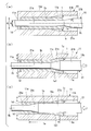
- FIG. 1A The dice 11 and the raw tube 1 are fixed. That is, the die 11 is fixed to a base (not shown). Further, in the raw tube 1, the end of the raw tube 1 on the left side of the paper surface is dammed so as not to go deeper further to the left side of the paper surface, so that the relative position in the longitudinal direction of the raw tube 1 with respect to the die 11 is fixed. ing. After the element tube 1 is fixed in the die 11, the small diameter tip 21 a of the plug 21 is inserted from the one end 1 a side of the element tube 1 toward the hollow portion 1 b of the element tube 1.
- the taper portion 21c and the large-diameter base end portion 21b of the plug 21 are connected to the element tube 1 while the die 11 and the element tube 1 are fixed. Is pushed into one end 1a.
- the plug 21 is pushed in until the tapered portion 21 c reaches the position of the tapered portion 11 c of the die 11. Until the taper portion 21c reaches the position of the taper portion 11c of the die 11 in this way, the relative position of the raw tube 1 with respect to the die 11 is kept fixed. Therefore, the raw tube 1 is fixed to the die 11 by the taper portion 21c. It will not be pushed out from. Whether or not the tapered portion 21c has reached the position of the tapered portion 11c can be managed, for example, by measuring the pushing stroke amount of the plug 21 or the reaction force that increases as the plug 21 is pushed.
- the locking portion 1e1 has a tapered truncated cone shape that forms a part of the intermediate portion 1e and has a tapered surface that is in close contact with the tapered portion 11c of the die 11 as an outer peripheral surface.
- the plug 21 is connected to the other end 1d of the tube 1 while the die 11 is maintained and the tube 1 is released. Push further toward the side. That is, as shown in FIG. 1B, after the enlarged diameter portion 1 c is formed, the damming of the raw tube 1 to the left end of the paper surface is released, and then the plug 21 is further pushed. When the plug 21 is further pushed in, the raw tube 1 is pushed from the one end 1a toward the other end 1d.
- the locking portion 1e1 formed in the raw tube 1 in the previous step is a tapered portion of the die 11. Since it remains locked to 11c, the raw tube 1 does not move.
- the large-diameter base end portion 21 b of the plug 21 is pushed toward the other end portion 1 d side of the raw tube 1. Expanding the size of the intermediate portion 1e of the raw pipe 1 a large diameter base end portion 21b is pushed in the plug 21, the inner diameter d 2 of the original raw pipe 1 corresponds to the diameter of the large diameter base end portion 21b of the plug 21 Diameter.
- the intermediate portion 1e of the base pipe 1 because the outer diameter is restricted from the ambient located in the hollow small-diameter portion 11a of the die 11, the outer diameter d 1 of the intermediate portion 1e is not enlarged.
- the intermediate portion 1e of the raw tube 1 is subjected to ironing while the original outer diameter d1 of the raw tube 1 is maintained.
- the reason for releasing the bar of the raw pipe 1 immediately before the start of the ironing process is that it does not hinder the flow of the meat of the pipe 1 accompanying the ironing process. That is, when the intermediate portion 1e of the blank tube 1 is thinned by ironing, the blockage of the blank tube 1 is released in order to secure the destination of the thinned portion of the meat. This prevents the portion of the raw tube 1 on the left side of the drawing from buckling. In the present embodiment, since the thinned portion of the raw tube 1 due to the ironing process flows to the left side of the drawing, the entire length of the raw tube 1 is slightly longer than before the processing.
- the thickness reduction rate of the raw tube 1 by the ironing process needs to be 10% or more.
- the thinning rate of the blank tube 1 by ironing is preferably in the range of 10 to 90%.
- the thinning rate is in the range of 20 to 80%.
- the thickness reduction rate (%) is (d 0 ⁇ d) / d 0 when the thickness of the blank tube 1 before ironing is d 0 and the thickness of the intermediate portion 1e after ironing is d. X100 (%).
- the thickness d of the intermediate portion 1e after the ironing process is not uniform when viewed along the longitudinal direction of the raw tube 1, the numerical value obtained at the location where the thinning amount is the largest is obtained.
- the rate of thinning that is, in the intermediate portion 1e, a value determined by the highest point the difference obtained by subtracting the d from d 0 (equivalent strain amount) when viewed along its longitudinal direction, is employed as a thinning rate of above .
- the rate of thinning can be adjusted by changing the diameter of the large-diameter base end portion 21b of the plug 21. The above-mentioned appropriate range regarding the thickness reduction rate in ironing is the same in other embodiments described later.
- the tapered portion 21c and the large-diameter base end portion 21b of the plug 21 are pushed to a position before the other end portion 1d of the raw tube 1.
- the portion on the other end 1 d side of the intermediate portion 1 e of the raw tube 1 remains unprocessed.
- the “unprocessed” portion refers to a portion of the differential thickness steel pipe that has almost the same strength (tensile strength) or hardness as that of the unprocessed blank pipe 1 that is the base material.
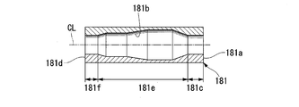
- FIG. 2 is a schematic cross-sectional view of the differential thickness steel pipe 31 manufactured through the steps shown in FIGS. 1 (a) to 1 (c).
- 31 is assigned as a new code in order to distinguish the manufactured differential thickness steel pipe from the raw pipe 1 before and during processing.
- the description is continued by giving a new sign, but in order to specify the correspondence with each part constituting the raw pipe 1, with parentheses, The sign of each part at the time of the raw tube 1 may be written together. The same applies to each embodiment described later.
- the differential thickness steel pipe 31 shown in FIG. 2 is on the one end 31a (1a) side and has a diameter-expanded portion 31c (1c) expanded from the raw tube 1, and one end 31a and the other end 31d (1d).
- the intermediate portion 31e (1e) which has been subjected to ironing processing in between, and the unprocessed portion 31f which is on the other end portion 31d side of the intermediate portion 31e and which has not been processed as the raw tube 1 is configured.
- the intermediate portion 31e also includes a portion processed by the taper portions 11c and 21c of the die 11 and the plug 21 at the respective boundaries between the enlarged diameter portion 31c and the unprocessed portion 31f.
- the intermediate portion 31e has a locking portion 31e1 (1e1) having a constant inner diameter and a tapered outer diameter when viewed from the one end portion 31a toward the other end portion 31d.
- the tube portion 31e2 and a tapered portion 31e3 having a constant outer diameter and a tapered inner diameter are included.
- the average value of the hardness of the enlarged diameter portion 31c is H1, the average value of the hardness of the unprocessed portion 31f is H3, the average value of the hardness of the locking portion 31e1 is H4, the average value of the hardness of the straight tube portion 31e2 is H5, When the average value of the hardness of the taper portion 31e3 is H6, both the expressions H5> H6 ⁇ H3 and H5>H4> H1 are satisfied.
- the enlarged diameter portion 31c is illustrated as a short ring shape for explanation, but may be a long straight tube shape as necessary.
- Hollow portion 31b of the different thickness steel tube 31, at the enlarged diameter portion 31c and the intermediate portion 31e of the original mother tube 1 is expanded than the inner diameter d 2, the unprocessed portion of 31f in the original mother tube 1 having an inner diameter d 2 It remains.
- Diameter The outer diameter of the different thickness steel tube 31 is gradually enlarged from the outer diameter d 1 of the base pipe 1 at the locking portion 31e1, and in the enlarged diameter portion 31c than the outer diameter d 1 of the base pipe 1 It remains constant.
- a portion except for the engaging portion 31e1 among the intermediate portions 31e, the unprocessed portion 31f has a left outer diameter equal to the outer diameter d 1 of the base pipe 1.
- the differential thickness steel pipe 31 has a relatively large thickness in the enlarged diameter portion 31c and the unprocessed portion 31f, and a relatively small thickness in the intermediate portion 31e.
- strength of the intermediate part 31e is comparatively high by work hardening. That is, when looking at the hardness distribution along the longitudinal direction of the differential thickness steel pipe 31 (Vickers hardness distribution. Note that the tensile strength distribution can be used instead of the Vickers hardness distribution), the hardness of the unprocessed portion 31f is the lowest.
- the hardness of the enlarged diameter part 31c is slightly higher than the hardness of the unprocessed part 31f, and the hardness of the intermediate part 31e is higher than the hardness of the enlarged diameter part 31c.
- the intermediate part 31e since the intermediate part 31e has the highest hardness, it is suitable as a part for which high mechanical strength is required. Moreover, the unprocessed part 31f and the enlarged diameter part 31c which have relatively low hardness are suitable as a part for which post-processing such as bending is required. Further, the inner surface of the intermediate portion 31e has a reduced surface roughness due to the ironing process. Since the fatigue characteristics increase when the surface roughness decreases, the intermediate portion 31e can improve the fatigue characteristics by reducing the surface roughness of the inner surface in addition to improving the strength by work hardening. Is realized. Such a synergistic effect cannot be obtained by thinning by simple cutting.
- FIG. 3 shows another example of the differential thickness steel pipe manufactured through the steps shown in FIGS. 1 (a) to 1 (c). 3 is manufactured by pushing the plug 21 until the large-diameter base end portion 21b of the plug 21 reaches the other end portion 1d of the base tube 1 in the step shown in FIG. It is a differential thickness steel pipe.
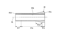
- the differential thickness steel pipe 41 shown in FIG. 3 is located on the one end 41a side, and has a diameter-expanded portion 41c (1c) that is expanded from the raw tube 1, and one end 41a (1a) and the other end 41d (1d).
- the intermediate portion 41e (1e) that has been subjected to ironing processing in between, and the other end portion 41f that is closer to the other end portion 41d than the intermediate portion 41e and subjected to ironing in the same manner as the intermediate portion 41e.
- the intermediate portion 41e also includes a portion subjected to processing by the tapered portion 11c of the die 11 and the tapered portion 21c of the plug 21 at the boundary with the enlarged diameter portion 41c. That is, the intermediate part 41e includes a locking part 41e1 (1e1). Since the locking portion 41e1 has the same shape as the locking portion 31e1, the duplicate description thereof is omitted here.
- the hollow portion 41 b of the differential thickness steel pipe 41 has a larger inner diameter in the longitudinal direction than the inner diameter d 2 of the raw pipe 1. Diameter The outer diameter of the different thickness steel tube 41 is gradually enlarged from the outer diameter d 1 of the base pipe 1 at the locking portion 41e1, and in the enlarged diameter portion 41c than the outer diameter d 1 of the base pipe 1 It remains constant. On the other hand, a portion except for the engaging portion 41e1 among the intermediate portions 41e, and the other end portion 41f, which remains as the outer diameter equal to the outer diameter d 1 of the base pipe 1.
- locking part 41e1 and the enlarged diameter part 41c is comparatively thick, and the difference thickness in which the thickness in the part except the latching
- one end portion 1a of the raw tube 1 is expanded to provide the locking portion 1e1 and the enlarged diameter portion 1c, and the locking portion 1e1.
- the plug 21 is further pushed into the raw tube 1 while being held in the die 11, so that the intermediate tube 1 is located on the other end 1 d side of the diameter-enlarged portion 1 c of the raw tube 1. Since ironing is performed to expand the inner diameter while maintaining the outer diameter, the amount of processing for the expanded portion 1c is small, and heat treatment such as annealing is performed when post-processing such as bending is performed on the expanded portion 1c. Can be made unnecessary.
- the plug 21 is pushed into the base tube 1 while the enlarged diameter portion 1c is locked to the die 11, the die 11 and the plug are connected to the die 11 without the need for labor and jigs for fixing the base tube 1 itself. Ironing can be performed simply by moving 21 relatively.
- the processing amount for the portion on the other end 1d side becomes zero, and the unprocessed portion 31f.
- heat treatment such as annealing can be made unnecessary.
- the differential thickness steel pipe 31 manufactured by the above method has a large thickness and a relatively low strength because the processed amount of the enlarged diameter portion 31c and the unprocessed portion 31f is small.
- the processing amount is large in the intermediate portion 31e, the thickness is thin and the strength is relatively high. Therefore, the diameter-expanded portion 31c and the unprocessed portion 31f are in a state in which the deformability remains compared to the intermediate portion 31e, and these portions are the differential thickness steel pipes 31 that are excellent in post-workability such as bending. Further, since the inner surface roughness of the intermediate portion 31e is reduced due to the ironing process, this portion is the differential thickness steel pipe 31 having excellent fatigue characteristics.
- the manufacturing method of the differential thickness steel pipe of the second embodiment uses a die and a plug, performs a pipe expanding process on a portion on one end side of the base pipe to form an enlarged diameter portion, and replaces the plug with another plug. Then, a step of ironing is performed to expand the inner diameter while maintaining the outer diameter of the raw tube with respect to the intermediate portion on the other end side from the expanded diameter portion.
- the raw tube to be processed in the present embodiment may be the same as that in the first embodiment.
- the same die and plug as those used in the first embodiment are used for the first step of forming the enlarged diameter portion. That is, as in the case of the first embodiment, as shown in FIG. 4A, the raw tube 1 is inserted into the die 11, and the one end 1 a of the raw tube 1 is inserted into the hollow large-diameter portion 11 b of the die 11. Position so that. The dice 11 and the raw tube 1 are fixed. And the small diameter front-end
- the taper portion 21c and the large-diameter base end portion 21b of the plug 21 are connected to the element tube 1 while the die 11 and the element tube 1 are fixed. Is pushed into one end 1a.
- the plug 21 is pushed in until the tapered portion 21 c reaches the position of the tapered portion 11 c of the die 11.
- the locking portion 1e1 and the enlarged diameter portion 1c are formed in the one end portion 1a of the raw tube 1.
- the pushed plug 21 is pulled out from the raw tube 1 in order to replace it with another plug.
- the die 11 is used continuously without being replaced.
- This another plug 51 includes a diameter 51b in having a small-diameter tip portion 51a which corresponds to the inner diameter d 2 of the base pipe 1, a larger diameter than the outer diameter of the inner diameter d 2 or small tip 51a of the base tube 1, A large-diameter base end portion 51c having a diameter larger than the diameter of the medium-diameter portion 51b, a first tapered portion 51d provided between the small-diameter distal end portion 51a and the medium-diameter portion 51b, and the medium-diameter portion 51b and the large-diameter And a second taper portion 51e provided between the base end portion 51c and the base end portion 51c.
- the diameter of the large-diameter base end portion 51 c is set to a dimension smaller than the inner diameter d 1 of the hollow small-diameter portion 11 a of the die 11. Moreover, the diameter of the small diameter front-end
- the plug 51 is removed from the one end 1a of the tube 1 while the die 11 is fixed and the tube 1 is released. Push toward the end 1d.
- the plug 51 By pushing the plug 51, the element tube 1 is pushed from the one end 1 a toward the other end 1 d, but the locking portion 1 e 1 formed on the element tube 1 in the previous step is a tapered portion 11 c of the die 11. It does not move because it remains locked.
- the plug 51 is pushed in until the tip of the small diameter tip 51a protrudes from the other end 1d of the raw tube 1.
- the medium diameter part 51 b and the large diameter base end part 51 c of the plug 51 are pushed into the intermediate part 1 e of the raw tube 1.
- the inner diameter d 2 of the original raw pipe 1 is expanded to a size corresponding to the diameter of the diameter portion 51b and large diameter end portion 51c in the plug 51.
- the intermediate portion 1e of the base pipe 1 because it has located in the hollow small-diameter portion 11a of the die 11, the outer diameter d 1 in the intermediate portion 1e is not enlarged. Therefore, the intermediate portion 1e of the raw tube 1 is subjected to ironing while the original outer diameter d1 of the raw tube 1 is maintained except for the portion of the locking portion 1e1.
- the small diameter tip portion 51a is merely inserted into the portion on the other end 1d side of the intermediate portion 1e of the raw tube 1 and remains unprocessed.
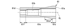
- FIG. 6 shows a schematic cross-sectional view of the differential thickness steel pipe 61 manufactured through the steps shown in FIGS. 4 (a) to 5 (b).
- the differential thickness steel pipe 61 shown in FIG. 6 is on one end 61a side and has a diameter-expanded portion 61c (1c) that is expanded from the raw tube 1, and one end 61a (1a) and the other end 61d (1d).
- An intermediate portion 61e (1e) that has been subjected to ironing processing in between, and an unprocessed portion 61f that is closer to the other end portion 61d than the intermediate portion 61e and remains unprocessed as the raw tube 1.
- the intermediate portion 61e also includes a portion processed by the tapered portion 11c of the die 11 and the tapered portions 51d and 51e of the plug 51 at the boundary between the enlarged diameter portion 61c and the unprocessed portion 61f. That is, the intermediate part 61e includes a locking part 61e1 (1e1). Since the locking portion 61e1 has the same shape as the locking portion 31e1, the duplicate description thereof is omitted here.
- the inner diameter of the hollow portion 61b of the different thickness steel tube 61 is expanded than the inner diameter d 2 of the base pipe 1 in the enlarged diameter portion 61c and the intermediate portion 61e, and in unprocessed portion 61f of the inner diameter d 2 of the base pipe 1 It remains.
- the inner diameter of the portion on the one end 61a side is increased by the large-diameter base end portion 51c of the plug 51, and the inner diameter of the portion on the other end 61d side is increased by the middle-diameter portion 51b of the plug 51.
- the inner diameters are different from each other.
- the outer diameter of the different thickness steel tube 61 is expanded than the outer diameter d 1 of the base pipe 1 at the locking portion 61e1 and the enlarged diameter portion 61c.
- a portion except for the engaging portion 61e1 of the intermediate portion 61e, the outer diameter of the unprocessed portion 61f is stuck in the outer diameter d 1 of the base pipe 1.
- the thickness difference portion 61c and the unprocessed portion 61f have a relatively thick wall thickness
- the intermediate portion 61e has a relatively thin thickness difference steel pipe 61.
- the intermediate portion 61e of the differential thickness steel pipe 61 since the amount of processing for the intermediate portion 61e of the differential thickness steel pipe 61 is relatively large, the intermediate portion 61e has a relatively high strength due to work hardening.
- the intermediate portion 1e of the raw tube 1 is ironed by the plug 51.
- the inner diameter and the strength of the intermediate portion 1e are different by increasing the diameter expansion amount of the region on the diameter expansion portion 1c side of the intermediate portion 1e larger than the diameter expansion amount of the region on the other end 1d side.
- One region can be provided.
- the diameter expansion amount in the region on the diameter expansion portion 61c side is larger than the diameter expansion amount in the region on the other end portion 61d side, and the diameter expansion portion 61c.
- the processing amount in the side region is larger than the processing amount in the region on the other end 61d side. Therefore, the thickness difference steel pipe 61 which has the area
- a manufacturing method of the differential thickness steel pipe of the third embodiment will be described with reference to FIGS. 7 (a) to 7 (c).
- the manufacturing method of the difference thickness steel pipe of this embodiment is comprised from the process similar to 1st Embodiment.
- the differential thickness steel pipe is manufactured using a plug 71 different from the plug 21 used in the first embodiment. Since other points are the same as those of the first embodiment, description thereof is omitted.
- the plug 71 used in the present embodiment has a tapered tip end portion 71 c having a tip end portion 71 a smaller than the inner diameter d 2 of the raw tube 1 and a larger inner diameter d 2 of the raw tube 1. And a base end portion 71b having a diameter. Further, the diameter of the base end portion 71 b is set to a dimension smaller than the inner diameter d 1 of the hollow small diameter portion 11 a of the die 11.
- the taper tip 71c of the plug 71 and the plug 71 are fixed in the state in which the die 11 and the raw tube 1 are fixed as a diameter expanding step.
- the base end portion 71 b is pushed into the one end portion 1 a of the raw tube 1.
- the plug 71 is pushed in until the taper tip 71c reaches the position of the taper 11c of the die 11. Thereby, the latching
- FIG. 7B the taper tip 71c of the plug 71 and the plug 71 are fixed in the state in which the die 11 and the raw tube 1 are fixed as a diameter expanding step.
- the plug 11 is connected to the other end 1 d of the tube 1 while the die 11 is fixed and the tube 1 is released. Push further toward the side.
- the plug 71 is further pushed in, the raw tube 1 is pushed from the one end 1a toward the other end 1d.
- the locking portion 1e1 formed on the raw tube 1 in the previous step is a tapered portion of the die 11. It will not move because it remains locked to 11c.
- the plug 71 in the present embodiment is composed of a tapered distal end portion 71c and a proximal end portion 71b, and since there is no small diameter distal end portion 21a shown in the first embodiment, the length in the longitudinal direction is relatively long. Is shorter. Therefore, compared to the first embodiment, when the plug 71 is inserted into the raw tube 1 or when the plug 71 is pulled out from the raw tube 1, the required stroke amount of the plug 71 is shortened. As a result, the work time required for inserting and removing the plug 71 can be shortened, and a simple hydraulic cylinder (not shown) for inserting and removing the plug 71 can be adopted, so that processing can be performed with relatively small manufacturing equipment.
- the differential thickness steel pipe manufactured through the steps shown in FIGS. 7A to 7C has the same shape as the differential thickness steel pipe 31 shown in FIG. 7C, the plug 71 is pushed in until the base end 71b of the plug 71 reaches the other end 1d of the base tube 1, so that the same shape as the differential steel pipe 41 shown in FIG. May be processed.
- the plug 71 at the time of manufacture is compared with the first embodiment.
- the required stroke amount can be made relatively small.
- the manufacturing method of the differential thickness steel pipe of 4th Embodiment is demonstrated.
- the manufacturing method of the difference thickness steel pipe of this embodiment is comprised from the process similar to 2nd Embodiment.
- the ironing process is performed using a plug 81 different from the plug 51 used in the ironing process of the second embodiment. Since other points are the same as those of the second embodiment, description thereof is omitted.
- Plug 81 has a tapered tip portion 81c having a smaller distal end portion 81a than the inner diameter d 2 of the blank tube 1, the hollow small-diameter portion 11a of larger diameter and die 11 than the inner diameter d 2 of the base pipe 1 inside diameter d 1 of less than And a base end portion 81b having a diameter.
- the taper tip 81c of the plug 81 is longer than the length of the taper tip 71c of the plug 71 shown in FIG.
- the plug 81 is moved from one end 1a of the raw tube 1 to the other while maintaining the fixing of the die 11 while releasing the fixing of the raw tube 1. Push toward the end 1d.
- the plug 81 By pushing the plug 81, the raw tube 1 is pushed from the one end 1a toward the other end 1d, but the locking portion 1e1 formed in the raw tube 1 in the previous step is a tapered portion 11c of the die 11.
- the element tube 1 does not move.
- the plug 81 is pushed in until the distal end portion 81 a of the plug 81 protrudes from the other end portion 1 d of the raw tube 1.
- the tapered tip 81 c of the plug 81 is pushed into the intermediate portion 1 e of the raw tube 1.
- the inner diameter d 2 of the original raw tube 1 is expanded to a size corresponding to the diameter of the tapered tip portion 81 c of the plug 81.
- the inner diameter of the intermediate portion 1e of the raw tube 1 is the same as the outer diameter of the taper tip 81c of the plug 81 over the entire length. . That is, the inner diameter of the intermediate portion 1e of the raw tube 1 is gradually expanded from the other end portion 1d side to the one end portion 1a side.
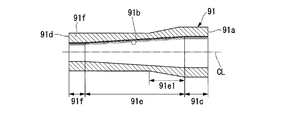
- FIG. 9 shows a schematic cross-sectional view of the differential thickness steel pipe manufactured according to this embodiment.
- the differential thickness steel pipe 91 shown in FIG. 9 is on the one end 91a (1a) side and has a diameter-increased portion 91c (1c) expanded from the raw tube 1, and one end 91a and the other end 91d (1d).
- An intermediate portion 91e (1e) that has been subjected to ironing processing in between, and an unprocessed portion 91f that is closer to the other end portion 91d than the intermediate portion 91e and that has not been processed as the raw tube 1 is configured.
- the inner diameter of the hollow portion 91b of the different thickness steel tube 91 is expanded than the inner diameter d 2 of the base pipe 1 in the enlarged diameter portion 91c and the intermediate portion 91e, and the remains of the inner diameter d 2 of the unprocessed portion 91f in base pipe 1 It has become.
- the outer diameter of the different thickness steel tube 91 is expanded than the outer diameter d 1 of the base pipe 1 at the locking portion 91e1 and the enlarged diameter portion 91c, and a portion except for the engaging portion 91e1 among the intermediate portions 91e, The unprocessed portion 91 f remains the outer diameter d 1 of the raw tube 1.
- the inner diameter of the intermediate portion 91e is gradually increased from the other end 1d side to the one end 1a side.
- the wall thickness in the enlarged diameter part 91c and the non-processed part 91f is comparatively thick.
- the locking portion 91e1 is gradually thinned, and the portion other than the locking portion 91e1 is gradually thickened. ing.
- the intermediate portion 91e of the differential thickness steel pipe 91 since the processing amount is gradually reduced from the enlarged diameter portion 91c to the unprocessed portion 91f, the intermediate portion 91e has a relatively high hardness on the enlarged diameter portion 91c side, On the unprocessed portion 91f side, the hardness is relatively low.
- the intermediate portion 1e of the raw tube 1 is ironed using the plug 81 having the relatively long tapered tip portion 81c. Therefore, in the intermediate part 1e, it is possible to manufacture a differential thickness steel pipe whose inner diameter gradually decreases from the enlarged diameter part 1c side to the other end part 1d side.
- the manufacturing method of the differential thickness steel pipe according to the fifth embodiment includes a step of forming the enlarged diameter portions 1c and 1f by performing tube expansion processing on both end portions of the raw tube 1 using one die and two plugs.
- the plug 21 on the other end side is pulled out while the plug 21 on the other side is inserted into the raw tube 1, and the outer diameter of the raw tube 1 is maintained with respect to the intermediate portion 1g located on the other end side from the enlarged diameter portion 1c on the one end side.
- the step of performing the first ironing process for expanding the inner diameter the plug 21 on one end side is removed from the raw tube 1, the plug 22 on the other end side is inserted into the raw tube 1, and the enlarged diameter portion 1f on the other end side
- the raw tube 1 to be processed in the present embodiment may be the same as that in the first embodiment.
- a die 12 shown in FIG. Die 12 has a hollow small-diameter portion 12b having an inner diameter corresponding to the outer diameter d 1 of the base tube 1, provided on both longitudinal sides of the hollow small-diameter portion 12b, having an inner diameter larger than the outer diameter d 1 of the base pipe 1 It is comprised from the hollow large diameter part 12a and the hollow large diameter part 12d.
- a tapered portion 12c is provided between the hollow small diameter portion 12b and the hollow large diameter portion 12a, and a tapered portion 12e is provided between the hollow small diameter portion 12b and the hollow large diameter portion 12d.
- the hollow large diameter portion 12a, the tapered portion 12c, the hollow small diameter portion 12b, the taper portion 12e, and the hollow large diameter portion 12d communicate with each other in the die body 12f.
- the dice 12 has a two-part structure that can be divided in the vertical direction of FIG. 10 (a) to 10 (d), the vertical alternate long and short dash line is a center line indicating the length in the longitudinal direction of the die 12, and the die 12 has the alternate long and short dash line as the axis of symmetry. It has a line-symmetric shape.
- the plug 22 has the same shape as the plug 21, a small-diameter distal end portion 22 a corresponding to the inner diameter d 2 of the raw tube 1, and a large-diameter base end portion 22 b having a diameter larger than the inner diameter d 2 of the raw tube 1.
- the tapered portion 22c is provided between the small-diameter distal end portion 22a and the large-diameter proximal end portion 22b.
- the diameter of the large-diameter base end portion 22 b is set to a dimension smaller than the inner diameter d 1 of the hollow small-diameter portion 12 b of the die 12.
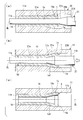
- the raw pipe 1 is inserted into the die 12 as shown in FIG. 10 (a). At this time, it positions so that the one end part 1a and the other end part 1d of the raw tube 1 may each be located in the hollow large diameter parts 12a and 12d of the die 12. Then, the small-diameter tip portion 21a of the plug 21 and the small-diameter tip portion 22a of the plug 22 are inserted into the hollow portion 1b of the raw tube 1 from the one end portion 1a side and the other end portion 1d side. At this time, the raw tube 1 and the die 12 are not fixed.
- the tapered portion 21c and the large-diameter base end portion 21b of the plug 21 are connected to the one end portion 1a of the raw tube 1, and the tapered portion 22c and the large-diameter portion of the plug 22 are combined.
- the base end portion 22b is pushed into the other end portion 1d of the raw tube 1 simultaneously.
- the plug 21 is pushed in until the tapered portion 21c reaches the position of the tapered portion 12c of the die 12, and the plug 22 is pushed in until the tapered portion 22c reaches the position of the tapered portion 12e of the die 12.
- locking part 1g1 and the enlarged diameter part 1c are formed in the one end part 1a side of the raw tube 1, and the latching
- the plug 22 on the other end 1d side is pulled out from the raw tube 1 while leaving the plug 21 on the one end 1a side.
- the other end 12g side of the die 12 is fixed, while the fixing of the raw tube 1 is released, and the plug 21 is removed. Further push toward the other end 1d side.
- the tube 1 is pushed from the one end 1a toward the other end 1d, but the locking portion 1g1 formed on the tube 1 in the previous step is a tapered portion of the die 12. Since it remains locked to 12c, the raw tube 1 does not move.
- the tapered portion 21c and the large-diameter base end portion 21b of the plug 21 are pushed to a position closer to the one end portion 12h than the intermediate position of the die 12.
- the diameter-enlarged portion 1 f on the other end 1 d side of the raw tube 1 and the first processed portion 1 g that has undergone ironing of the raw tube 1. The part between and remains unprocessed.
- the plug 21 is pulled out from the raw tube 1 and the plug 22 is inserted into the other end 1d side of the raw tube 1. And as shown in FIG.10 (d), the plug 22 is further pushed in toward the one end part 1a side of the raw tube 1 as a 2nd ironing process. At this time, the one end 12h side of the die is fixed while the raw tube 1 is not fixed. By pushing the plug 22 further, the tube 1 is pushed from the other end 1d side toward the one end 1a, but the locking portion 1h1 formed in advance in the tube 1 in the diameter expanding step is Since it is latched by the taper part 12e of the die
- the tapered portion 22c and the large-diameter base end portion 22b of the plug 22 are pushed from the middle of the die 12 to the position on the other end portion 12g side.
- the pushing of the plug 22 is stopped at the position shown in FIG. 10D, the intermediate portion 1i between the first processed portion 1g and the second processed portion 1h of the raw tube 1 remains unprocessed.
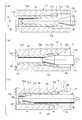
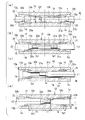
- FIG. 11 is a schematic cross-sectional view of the differential thickness steel pipe 111 manufactured through the steps shown in FIGS. 10 (a) to 10 (d).
- the differential thickness steel pipe 111 is located on the one end 111a (1a) side and is expanded between the enlarged diameter portion 111c (1c) and the other end 111d (1d).
- the first processed portion 111g also includes a portion that has been processed by the taper portions 12c and 21c of the die 12 and the plug 21 at the boundary between the enlarged diameter portion 111c and the unprocessed portion 111i.
- the first processed portion 111g includes a locking portion 111g1 (1g1) continuous with the enlarged diameter portion 111c and a tapered portion 111g2 continuous with the unprocessed portion 111i.
- the second processed portion 111h also includes portions that have been processed by the tapered portions 12c and 22c of the die 12 and the plug 22 at the boundaries between the enlarged diameter portion 111f and the unprocessed portion 111i. That is, the second processed portion 111h includes a locking portion 111h1 (1h1) that continues to the enlarged diameter portion 111f, and a tapered portion 111h2 that continues to the unprocessed portion 111i.
- Hollow section 111b of the different thickness steel tube 111 has a diameter portion 111c, and a first working portion 111 g, and the enlarged diameter portion 111f, a second working portion 111h, than the inner diameter d 2 of the original raw pipe 1 in diameter Has been.
- the raw portion 111i stuck in the inner diameter d 2 of the original raw pipe 1.
- the outer diameter of the different thickness steel tube 111 has a diameter portion 111c, a locking portion 111G1, and the enlarged diameter portion 111f, a locking portion 111H1, is diameter larger than the outer diameter d 1 of the base pipe 1 in Yes.
- the portion of the first processed portion 111g excluding the locking portion 111g1, the portion of the second processed portion 111h excluding the locking portion 111h1, and the unprocessed portion 111i are the outer diameter d of the raw tube 1. It remains at 1 .
- the differential thickness steel pipe is relatively thick in the enlarged diameter portion 111c, the enlarged diameter portion 111f and the unprocessed portion 111i, and relatively thin in the first processed portion 111g and the second processed portion 111h. It has become.
- the enlarged diameter portion 111c, the enlarged diameter portion 111f, and the unprocessed portion 111i since the amount of processing for the enlarged diameter portion 111c, the enlarged diameter portion 111f, and the unprocessed portion 111i is small, work hardening does not occur in this portion, or even if it occurs, it is negligible. It is. Accordingly, the enlarged diameter portion 111c, the enlarged diameter portion 111f, or the unprocessed portion 111i has a relatively low strength, so that even when post-processing such as bending is performed on this portion, work hardening is alleviated. Annealing is not necessary.
- the first processed portion 111g and the second processed portion 111h have relatively high strength due to work hardening.
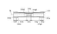
- FIG. 12 shows another example of the differential thickness steel pipe manufactured through the steps shown in FIGS. 10 (a) to 10 (d).
- the difference steel pipe 121 shown in FIG. 12 is manufactured by pushing the plug 22 until the large-diameter base end portion 22b of the plug 22 reaches the one end portion 1a of the base tube 1 in the step shown in FIG. Thick steel pipe.
- the differential thickness steel pipe 121 shown in FIG. 12 has an enlarged diameter part 121c (1c) that is enlarged from the element pipe 1 on the one end part 121a side and an expanded part from the element pipe 1 on the other end part 121d (1d) side. It is comprised from the diameter-expanded diameter part 121f (1c) and the intermediate part 121e (1e) which received the ironing process between the one end part 121a and the other end part 121d.
- the intermediate portion 121e includes a portion processed by the tapered portion 12c of the die 12 and the tapered portion 21c of the plug 21 at the boundary with the enlarged diameter portion 121c, and a tapered portion 12e of the die 12 at the boundary with the enlarged diameter portion 121f.
- the intermediate part 121e includes a locking part 121e1 (1g1) that is continuous with the enlarged diameter part 121c and a locking part 121e2 (1h1) that is continuous with the enlarged diameter part 121f.
- Hollow portion 121b of the different thickness steel tube 121 the entirety of the inner diameter of the longitudinal direction are diameter larger than the inner diameter d 2 of the base pipe 1.
- the outer diameter of the different thickness steel tube 121 has a diameter portion 121c, a locking portion 121e1,121e2 at both ends of the intermediate portion 121e, the enlarged diameter portion 121f, in, than the outer diameter d 1 of the base pipe 1
- the diameter has been expanded.
- the portion excluding the engaging portion 121e1,121e2 than the intermediate portion 121e has a left outer diameter d 1 of the base pipe 1.
- the differential thickness steel pipe 121 has a relatively large thickness at the enlarged diameter portion 121c and the enlarged diameter portion 121f and a relatively small thickness at the intermediate portion 41e.
- the intermediate part 121e since the amount of processing in the intermediate part 121e is relatively large, the intermediate part 121e has a relatively high strength due to work hardening.
- the differential thickness steel pipe 111 is manufactured by using one die 12 and two plugs 21 and 22. Therefore, the enlarged diameter part 1c (121c) and the enlarged diameter part 1f (121f) can be provided in the one end part 1a side and the other end part 1d side of the raw tube 1, respectively. Moreover, the area
- the differential thickness steel pipe 111 is manufactured using the die 12 having a line symmetry shape with the one-dot chain line in FIGS. 10A to 10D as the axis of symmetry. 12 may have a non-symmetrical shape or may be manufactured using two plugs having different shapes.
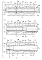
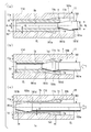
- FIGS. 13 (a) to 13 (c) a manufacturing method of the differential thickness steel pipe of the sixth embodiment will be described with reference to FIGS. 13 (a) to 13 (c).
- the manufacturing method of the difference thickness steel pipe of this embodiment is comprised from the process similar to 1st Embodiment.
- the differential thickness steel pipe is manufactured using a die 13 different from the die 11 used in the first embodiment. Since other points are the same as those of the first embodiment, description thereof is omitted.
- the hollow large diameter portion 13d, the tapered portion 13c, the first hollow small diameter portion 13a, the thick wall forming portion 13e, and the second hollow small diameter portion 13b communicate with each other in the die body 13i. Further, the dice 13 can be divided in the vertical direction on the paper surface of FIG.
- the thick portion 13e includes a hollow medium diameter part 13f, a taper part 13h provided between the hollow medium diameter part 13f and the first hollow small diameter part 13a, a hollow medium diameter part 13f, and a second hollow small diameter part 13b. And a tapered portion 13g provided between the two.
- the inner diameter d 3 of the medium air-diameter portion 13f has an outer diameter d 1 is larger than the inner diameter of the mother tube 1, is set to a smaller inner diameter than the inner diameter of the hollow large diameter portion 13d.
- the inner diameter is larger than the inside diameter d 3 of the medium air-diameter portion 13f is hollow large diameter portion 13d, the air-diameter portion 13f in during ironing process, remain in base tube 1 is not subject to thinning processing, it is pipe expanding Therefore, the thickness of the raw tube 1 in the thick wall forming portion 13e remains the original raw tube 1.
- a diameter expansion process is performed as shown in FIG. First, the small diameter distal end portion 21 a and the large diameter proximal end portion 21 b of the plug 21 are pushed into the one end portion 1 a of the raw tube 1 while the die 13 and the left end portion of the raw tube 1 are fixed. The plug 21 is pushed in until the tapered portion 21c reaches the position of the tapered portion 13c of the die 13. Thereby, the enlarged diameter part 1c and the latching
- the plug 21 is connected to the other end 1d of the base tube 1 in a state in which the fixing of the die 13 is maintained while the fixing of the base tube 1 is released. Push further toward the side.
- the plug 21 is further pushed in, the raw tube 1 is pushed from the one end 1a toward the other end 1d.
- the locking portion 1e1 formed on the raw tube 1 in the previous step is a tapered portion of the die 13. Since it remains locked to 13c, the raw tube 1 does not move. Tapered portion 21c and the large diameter base end portion 21b of the plug 21, when pushed to the position shown in FIG.
- the thickness of the raw tube 1 flows into the thick wall forming portion 13e. Thereby, the thick part 1j is formed in the raw tube 1.
- FIG. 14 shows a schematic cross-sectional view of the differential thickness steel pipe 141 manufactured through the steps shown in FIGS. 13 (a) to 13 (c).
- the differential thickness steel pipe 141 is on the one end 141a (1a) side, and is squeezed between the enlarged diameter portion 141c (1c) expanded from the raw tube 1 and the one end 141a and the other end 141d (1d).
- the intermediate portion 141e (1e) that has been processed and the unprocessed portion 141g that is on the other end portion 141d side of the intermediate portion 141e and remains unprocessed as the raw tube 1 are configured.
- the intermediate portion 141e includes a locking portion 141e1 (1e1) processed by the tapered portion 13c of the die 13 and the tapered portion 21c of the plug 21 at the boundary with the enlarged diameter portion 141c, and the thick-wall forming portion 13e and the plug of the die 13. And a thick portion 141 f processed by the 21 tapered portion 21 c.
- Hollow portion 141b of the different thickness steel tube 141 while being diameter larger than the inner diameter d 2 of the base pipe 1 in the enlarged diameter portion 141c and the intermediate portion 141e, the unprocessed portion of 141g in the original mother tube 1 having an inner diameter d 2 It remains.
- the inner diameters of portions excluding a part of the enlarged portion 141g and the intermediate portion 141e are constant, and the thick portion 141f and the enlarged portion 141c are different from each other.
- the difference thickness steel pipe 141 has a diameter.
- the intermediate portion 141e of the differential thickness steel pipe 141 since the amount of processing for the intermediate portion 141e of the differential thickness steel pipe 141 is relatively large, the intermediate portion 141e has a relatively high strength due to work hardening.
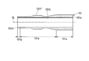
- FIG. 15 shows another example of the differential thickness steel pipe manufactured through the steps shown in FIGS. 13 (a) to 13 (c). That is, in this example, in the step shown in FIG. 13C, the plug 21 is pushed in until the large-diameter base end portion 21 b of the plug 21 reaches the other end portion 1 d of the raw tube 1.
- the differential thickness steel pipe 151 is processed.
- the differential thickness steel pipe 151 shown in FIG. 15 is on the one end 151a (1a) side and has a diameter-enlarged portion 151c (1c) expanded from the raw tube 1, and one end 151a and the other end 151d (1d).
- the intermediate portion 151e includes a portion processed by the taper portion 13c of the die 13 and the taper portion 21c of the plug 21 at the boundary with the enlarged diameter portion 151c, a thick-wall forming portion 13e of the die 13, and a taper portion 21c of the plug 21. And a thick portion 151f that has been subjected to processing.
- the hollow portion 151 b of the differential thickness steel pipe 151 has a larger inner diameter in the longitudinal direction than the inner diameter d 2 of the raw pipe 1.
- the outer diameter of the different thickness steel tube 151 is enlarged than the outer diameter d 1 of the base pipe 1 in the enlarged diameter portion 151c and the thick portion 151f, the middle portion 151e and the other end portions 151g of the non-thick portion 151f It stuck in the outer diameter d 1 of the hollow shell 1.
- the differential thickness steel pipe 151 has a plurality of portions having constant inner diameters in the longitudinal direction and different outer diameters.
- the intermediate portion 151e and the other end portion 151g of the differential thickness steel pipe 151 since the amount of processing for the intermediate portion 151e and the other end portion 151g of the differential thickness steel pipe 151 is relatively large, the intermediate portion 151e and the other end portion 151g have a relatively high strength due to work hardening.
- the die 13 having the thick wall forming portion 13 e between the first hollow small diameter portion 13 a and the second hollow small diameter portion 13 b is used.
- the differential thickness steel pipe 141 is manufactured. Therefore, the differential thickness steel pipe 141 which has the thick part 1j (141f) in the intermediate part 1e (141e) of the elementary pipe 1 can be manufactured. Moreover, the difference thickness steel pipe 141 which has a different outer diameter by the thick part 1j and the enlarged diameter part 1c (141c) can be manufactured.
- the differential thickness steel pipe 141 has a relatively low processing amount on the other end 1d (141d) side than the enlarged diameter portion 1c and the intermediate portion 1e, and thus has a low strength, while the intermediate portion 1e including the thick portion 1j.
- the strength is high.
- the manufacturing method of the difference thickness steel pipe of this embodiment is comprised from the process similar to 1st Embodiment.
- the differential thickness steel pipe is manufactured using a plug 161 different from the plug 21 used in the first embodiment. Since other points are the same as those of the first embodiment, description thereof is omitted.
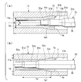
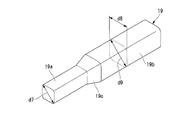
- Plug 161 used in this embodiment as shown in FIG. 16 (a), and a taper end portion 161b having a tip portion 161a of the outer diameter smaller than the inner diameter d 2 of the blank tube 1, the inner diameter d 2 of the base pipe 1 small diameter proximal portion 161e having a large diameter portion 161c having a diameter d 5 of less than the inner diameter d 1 of the hollow small-diameter portion 11a of the large and die 11 than the smaller diameter d 4 than the diameter d 5 of the large-diameter portion 161c And is composed of.
- a tapered portion 161d is provided between the large-diameter portion 161c and the small-diameter base end portion 161e.
- the tapered tip end portion 161b and the large diameter portion 161c of the plug 161 are left in a state where the left side of the die 11 and the blank tube 1 is fixed. Is pushed into one end 1a of the tube 1. The plug 161 is pushed in until the tapered tip portion 161b reaches the position of the tapered portion 11c of the die 11. Thereby, the enlarged diameter part 1c and the latching
- the plug 161 is directed toward the other end 1 d side of the raw tube 1 in a state where the fixing of the die 11 is maintained while the fixing of the raw tube 1 is released. Push further. By pushing the plug 161 further, the tube 1 is pushed from the one end 1a toward the other end 1d.
- the locking portion 1e1 formed in the tube 1 in the previous step is a tapered portion of the die 11. Since it remains locked to 11c, the raw tube 1 does not move.
- the inner diameter d 2 of the original pipe 1 is the large diameter of the plug 161 in the intermediate part 1 e of the pipe 1 into which the large diameter part 161 c of the plug 161 is pushed. It is expanded to a size corresponding to the diameter d 5 parts 161c.
- the small-diameter base end portion 161e that follows the large diameter portion 161c of the plug 161 since the diameter d 4 is less than the diameter d 5 of the large-diameter portion 161c, the small-diameter base end portion 161e is ironing the mother tube 1 Do not touch the affected part.
- the plug 161 is in contact with the element tube 1 only in the tapered tip portion 161b and the large diameter portion 161c.
- the portion of the plug 161 that contacts the base tube 1 is reduced as compared with the first embodiment, so that the frictional resistance between the base tube 1 and the plug 161 in the ironing process is reduced.
- the difference (d 5 -d 4 ) between the diameter d 4 of the small-diameter base end portion 161e of the plug 161 and the diameter d 5 of the large-diameter portion 161c in FIG. 16 (a) is preferably in the following range. That is, the thickness of the mother tube 1 and d 0, when the thickness of the intermediate portion 1e after ironing was d, the difference between d 0, d a (d 0 -d) and thickness reduction t d defined To do.
- the difference between the thickness reduction t d, the diameter d 4 of the small-diameter base end portion 161e to the diameter d 5 of the large-diameter portion 161c (d 5 -d 4) is, 2 ⁇ t d ⁇ (d 5 -d 4 ).
- the difference between the diameter d 5 of the small-diameter base end portion 161e to the diameter d 4 of the large diameter portion 161c (d 5 -d 4) is a 2 ⁇ t d greater than the combination of strength and thickness reduction of the material is In the ironing process shown in FIG. 16 (c), the locking portion 1 e 1 of the base tube 1 cannot be locked to the tapered portion 11 c of the die 11.
- the differential thickness steel pipe manufactured through the steps shown in FIGS. 16A to 16C has the same shape as the differential thickness steel pipe 31 shown in FIG. Further, in the step shown in FIG. 16C, the plug 161 is pushed in until the large-diameter portion 161c of the plug 161 reaches the other end portion 1d of the raw tube 1, so that the same shape as that of the differential thickness steel pipe 41 shown in FIG. May be processed.
- the plug 161 having the small-diameter base end portion 161e having a diameter smaller than the diameter of the large-diameter portion 161c by manufacturing the differential thickness steel pipe using the plug 161 having the small-diameter base end portion 161e having a diameter smaller than the diameter of the large-diameter portion 161c,
- the ironing process can be performed without contact between the small-diameter base end portion 161e and the portion of the raw tube 1 that has undergone ironing. That is, when the plug 161 is pushed in, only the tapered tip portion 161b and the large diameter portion 161c are in sliding contact with the inner surface of the element tube 1, and when the plug 161 is pulled out, only the large diameter portion 161c is mainly formed in the element tube 1. Touch the inner surface.
- the small-diameter base end portion 161e does not slide in contact with the inner surface of the raw tube 1, so that the raw tube when the plug 161 is inserted and removed in the ironing process as compared with the first embodiment.
- the frictional resistance between 1 and the plug 161 can be reduced, and the force required for processing can be prevented from becoming excessive.
- the manufacturing method of the differential thickness steel pipe of the eighth embodiment includes a step of drawing after the ironing of the first to fourth embodiments, the sixth embodiment, and the seventh embodiment. .
- the differential thickness steel pipe 61 manufactured through the steps of the second embodiment is used as an intermediate product 15, and the intermediate product 15 is drawn.
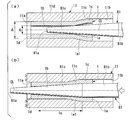
- An intermediate product 15 shown in FIG. 17A is a differential steel pipe 61 manufactured through the steps of the second embodiment.
- the intermediate product 15 includes a diameter-enlarged portion 15c that is expanded from the raw tube 1 on the one end portion 15a side, an intermediate portion 15e that is subjected to ironing between the one end portion 15a and the other end portion 15d, and an intermediate portion It is comprised from the unprocessed part 15f which is in the other end part 15d side rather than 15e, and has not received the process with the raw tube 1.
- FIG. The intermediate portion 15e was processed by the tapered portion 11c of the die 11 and the tapered portions 51d and 51e of the plug 51 used in the second embodiment at the boundary between the enlarged diameter portion 15c and the unprocessed portion 15f. Including parts.
- a die 14 shown in FIG. 17A includes a hollow small diameter portion 14b having an inner diameter corresponding to the outer diameters of the unprocessed portion 15f and the intermediate portion 15e of the intermediate product 15, and a tapered portion 14c connected to the hollow small diameter portion 14b. It is configured.
- the “inner diameter corresponding to the outer diameter of the unprocessed portion 15f and the intermediate portion 15e” described above can be inserted into and removed from the outer diameter of the unprocessed portion 15f and the intermediate portion 15e. This shows the diameter dimension with a gap size of about.
- the hollow small diameter part 14b and the taper part 14c are connected in the die main body 14e.
- the outer diameter of the unprocessed portion 15f and the middle portion 15e of the intermediate product 15 is the same as the outer diameter d 1 of the base tube 1, the inner diameter of the hollow small-diameter portion 14b corresponding to the outer diameter d 1 of the base pipe 1.
- the inner diameter of the tapered portion 14c becomes a maximum diameter at one end 14a side of the die 14, the inner diameter d 6 of the position is set to a larger dimension than the outer diameter of the enlarged diameter portion 15c of the intermediate product 15.
- the manufacturing method of the differential thickness steel pipe by this embodiment is demonstrated.
- the intermediate product 15 is manufactured. Since the manufacturing method of the intermediate product 15 is the same as that of the second embodiment, the description thereof is omitted.
- the intermediate product 15 is inserted from the one end portion 14 a side of the die 14 toward the other end portion 14 d side in a state where the die 14 is fixed.
- the locking portion 15e1 of the intermediate product 15 reaches the position of the taper portion 14c of the die 14, the enlarged diameter portion 15c is locked to the taper portion 14c, but further pushes the intermediate product 15 toward the other end portion 14d.
- FIG. 18 is a schematic cross-sectional view of the differential thickness steel pipe 181 manufactured according to this embodiment.
- This differential thickness steel pipe 181 is on one end 181a (15a) side, and corresponds to a reduced diameter portion 181c in which the enlarged diameter portion 15c of the intermediate product 15 has been subjected to drawing processing, and a locking portion 15e1 which has also been subjected to drawing processing. Part to be included.
- the other parts of the differential thickness steel pipe 181 are the intermediate part 181e (15e) that has not been subjected to the drawing process as the intermediate product 15, and the unprocessed part 181f (15f) that has not been subjected to the drawing process as the intermediate product 15. Consists of
- the hollow portion 181b of the differential thickness steel pipe 181 has the entire outer diameter in the longitudinal direction as the outer diameter of the raw pipe 1.
- the inner diameter of the different thickness steel tube 181 remains inside diameter d 2 of the base pipe 1 in the reduced diameter portion 181c and the unprocessed portion 181f, and a larger diameter than the intermediate portion the inner diameter d 2 of the base pipe 1, 181e . Therefore, the differential thickness steel pipe 181 has a plurality of regions in which the entire outer diameter in the longitudinal direction is constant and the inner diameter is different from each other at each position in the longitudinal direction.
- the difference-thickness steel pipe 181 has a relatively large thickness at the reduced diameter portion 181c and the unprocessed portion 181f, and a relatively small thickness at the intermediate portion 181e.
- the differential thickness steel pipe 181 since the amount of processing with respect to the unprocessed portion 181f is small, work hardening does not occur in this portion, or even if it occurs, it is very small. Therefore, since the strength of the unprocessed portion 181f is relatively low, even if post-processing such as bending is performed on this portion, an annealing process or the like for relaxing work hardening is not necessary.
- the differential thickness steel pipe 61 manufactured in the second embodiment is illustrated as the intermediate product 15, but the present embodiment is not limited to this.
- the intermediate product in the present embodiment may be, for example, the differential thickness steel pipe 31 manufactured in the first embodiment shown in FIG.
- the inner diameter of the hollow small-diameter portion 14b of the die 14 used in the present embodiment may be an inner diameter smaller than the outer diameter of the raw tube 1 in order to perform drawing processing on the entire outer surface of the intermediate product 15. Good.
- the inner diameter of the hollow small-diameter portion 14b of the die 14 is too small with respect to the outer diameter of the raw tube 1, the squeezing ratio becomes too large, and buckling may occur during the drawing process.
- the aperture ratio at this time will be described below.
- the ratio of the thickness of a steel pipe to the outer diameter of the steel pipe (t / D 0 , t: the thickness of the raw pipe, D 0 : the outer diameter of the raw pipe) is 0.001 to 0 for the steel pipe for automobiles. .15 steel pipes are used.
- the drawing ratio should be 0.4 or less. Therefore, when drawing is performed on the entire outer surface of the intermediate product 15, the inner diameter of the hollow small diameter portion 14b of the die 14 may be set so that the aperture drawing ratio is 0.4 or less.
- the drawing ratio is expressed by the following formula (1), ⁇ in the following formula (1) is the drawing ratio, D 0 is the outer diameter of the steel pipe before drawing, and D is after drawing. The outer diameter of the steel pipe.
- the differential thickness steel pipe 181 having a plurality of regions in which the entire outer diameter of the raw pipe 1 in the longitudinal direction is constant and the inner diameters are different from each other.
- the differential thickness steel pipe 181 has a relatively small amount of processing with respect to the unprocessed portion 181f, so that the strength of this region is relatively low, and the amount of processing with respect to the reduced diameter portion 181c and the intermediate portion 181e is relatively large. The strength of is relatively high.
- a ninth embodiment will be described.
- the manufacturing method of the difference thickness steel pipe of this embodiment is comprised from the process similar to 1st Embodiment.
- the differential thickness steel pipe is manufactured using a plug different from the plug 21 used in the first embodiment and the die 11 used in the first embodiment.
- the differential thickness steel pipe is manufactured using a die different from the die 11 used in the first embodiment and the plug 21 used in the first embodiment. Since other points are the same as those of the first embodiment, description thereof is omitted.
- a method for manufacturing a differential steel pipe using a plug different from the plug 21 used in the first embodiment and the die 11 used in the first embodiment will be described. explain.
- the plug 19 shown in FIG. 19 has a different shape from the plug 21 shown in FIG.
- the cross-sectional shape orthogonal to the longitudinal direction of the plug 19 is a rounded square shape in the entire longitudinal direction.
- the plug 19 includes a small distal end portion 19a, a large proximal end portion 19b, and a tapered portion 19c provided between the small distal end portion 19a and the large proximal end portion 19b.
- a diagonal length d7 has a diameter corresponding to the inner diameter d 2 of the base pipe 1.
- one side of the rounded rectangles length d8 corresponds to the inner diameter d 2 of the blank tube 1
- the diagonal length d9 is than the inner diameter d 2 of the base pipe 1 and large and becomes an inner diameter d less than one hollow small-diameter portion 11a of the die 11 also.
- a schematic cross-sectional view perpendicular to the longitudinal direction of the intermediate portion subjected to ironing is a shape shown in FIG. become.
- large base end portion 19b of the plug 19 corresponding side length d8 is the inner diameter d 2 of the blank tube 1, because the major diameter d9 is greater than the inner diameter d 2 of the base pipe 1, the different thickness steel tube produced by the plug 19
- the intermediate part of 20A has the unprocessed part 20a which has not received the process with the raw tube 1, and the to-be-processed part 20b which received the ironing process.
- the unprocessed portion 20a has a relatively low strength because the thickness of the unprocessed portion 20a remains as it is and the amount of processing is small.
- the processed part 20b has a relatively high thickness because it is relatively thin and has a large amount of processing. Therefore, the difference thickness steel pipe 20A manufactured by this embodiment has the part which received the ironing process, and the part which has not been processed in the middle part which received the ironing process by turns along the circumferential direction.
- the differential thickness steel pipe 20A is manufactured by a process similar to that of the first embodiment using the plug 19 having a rounded quadrangular cross section perpendicular to the longitudinal direction and the die 11.
- plugs having other shapes in the cross-sectional shape orthogonal to the longitudinal direction may be used.
- the cross section orthogonal to the longitudinal direction of the plug may be rotationally symmetric. The reason is that when the cross section perpendicular to the longitudinal direction of the plug is not rotationally symmetric, the diameter-expanded portion cannot be sufficiently formed by the tube-expanding process, and the element tube 1 is locked to the tapered portion 11c of the die 11. Because you can't. 20 (b) and FIG.
- 20 (c) are cross sections orthogonal to the longitudinal direction in the eighth embodiment in the intermediate part of the differential thickness steel pipes 20B and 20C manufactured using another plug having a rotationally symmetric shape. It is a figure which shows the cross section orthogonal to a longitudinal direction.
- the cross-sectional shape orthogonal to the longitudinal direction of the die is preferably rotationally symmetric so that the tube expansion process can be sufficiently performed.
- the outer shape of the raw tube 1 must be a shape corresponding to a die. For example, when the difference thickness steel pipe 20D is manufactured similarly to the first embodiment using a square steel pipe, a die having a shape corresponding to the square steel pipe, and the plug 21 similar to the first embodiment, the difference is obtained.
- the cross-sectional shape orthogonal to the longitudinal direction in the middle portion of the thick steel pipe 20D is the shape shown in FIG. FIG. 20 (e) shows a difference-thickness steel pipe manufactured by the same method as that of the first embodiment using a die 21 and a plug 21 having a shape corresponding to that of the base pipe, and the outer shape of the base pipe is an elliptical shape.
- the differential thickness steel pipe that alternately has the portions that have undergone the ironing process and the unprocessed parts in the circumferential direction. 20A can be manufactured. Further, the difference thickness steel pipe 20A has a relatively high strength because the portion subjected to the ironing process is thin and has a large amount of processing. On the other hand, the unprocessed portion has a relatively small strength because its thickness is thick and the processing amount is small.
- the pipe is expanded to provide a locking portion, and the plug is kept while the locking portion is locked to the die.
- ironing is performed on the intermediate portion on the other end side of the diameter-enlarged portion of the element tube to increase the inner diameter while maintaining the outer diameter of the element tube. Therefore, the amount of processing for the enlarged diameter portion is small, and heat treatment such as annealing can be eliminated when post-processing such as bending is performed on the enlarged diameter portion.
- the plug since the plug is pushed into the base tube while the locking part is locked to the die, the base tube itself does not need to be fixed during the ironing process, and the die and plug are simply moved relative to each other. Can be implemented.
- differential thickness steel pipe in each embodiment of the present invention in automobile parts, a cross member, a suspension member, a frame member such as a suspension arm, a collision-compatible part such as a perimeter and a side impact bar, or a drive shaft Drive system pipe parts.
- frame members such as cross members, suspension arms, suspension members, etc.
- particularly thick parts are required for attachment parts of other parts, so if the differential thickness steel pipe in each embodiment of the present invention is used, only necessary portions are used. It is possible to adopt a light-weight structure that is thickened.
- press work or bending may be performed during post-processing of forming the thick portion into a predetermined shape.
- the side impact bar is a member that is installed in the door panel and transmits the collision energy at the time of collision to both sides of the door, and is desirably not broken at the time of the collision. Therefore, if the central portion is thickened using the differential thickness steel pipe in each embodiment of the present invention, a lightweight structure can be obtained.
- the perimeter is a frame member at the front of the vehicle body and is a member that serves as a load transmission path at the time of a frontal collision.
- the perimeter can be further reduced in weight by making a bent portion or the like that is easily bent at the time of a collision into a thick part.
- the difference thickness steel pipe in each embodiment of this invention can be used suitably.
- the drive shaft may be splined in the differential thickness portion at the pipe end, and if this portion is thick and low in strength, it is easy to process, so the differential thickness steel pipe in each embodiment of the present invention is preferably used. be able to.
- the manufacturing method of the differential thickness steel pipe according to the first embodiment described with reference to FIGS. 1 (a) to 2 is based on the difference thickness steel pipe 31 from the hollow cylindrical (hollow cylindrical) base pipe 1.
- a plug is inserted from one end side (one end 1a) of the raw tube 1
- the plug 21 is pushed further toward the other end side (the other end 1d) of the element tube 1 while maintaining the locking, so that the outer shape (outer diameter) of the element tube 1 is maintained while maintaining the outer shape (outer diameter).
- an ironing process for forming a thin-walled portion 1e (31e) by applying ironing to expand the inner diameter).
- the plug 21 provided with the above may be used.
- the differential thickness steel pipe according to any one of the above (1) to (3) In the manufacturing method, the outer dimension (outer diameter dimension) larger than the inner dimension (inner diameter dimension) of the element tube 1 and less than the outer dimension (outer diameter dimension) of the element tube 1 in the locking step and the ironing step.
- the base end portion is a large base end portion (large diameter portion 161c) disposed on the tip end side, and a small base end portion (small diameter) having an outer dimension (outer diameter size) smaller than that of the large base end portion.
- the manufacturing method of the differential thickness steel pipe according to the second embodiment described with reference to FIGS. 4A to 6 uses the differential thickness steel pipe 61 from the hollow cylindrical (hollow cylindrical) base pipe 1.
- the raw tube 1 is disposed in a die 11 and the movement of the raw tube 1 in the longitudinal direction is restricted, and the first tube 1 is connected to one end side (one end 1a).
- a second plug (plug 51) having a different external shape from the one end side (one end 1a) of the base tube 1 is provided.
- a thin portion 1e (61e) is formed by applying a squeezing process that expands the inner shape (inner diameter) while maintaining the outer shape (outer diameter) of the raw tube 1.
- the inner dimensions of the raw pipe 1 A small tip portion (small diameter tip portion 51a) smaller than (inner diameter size) and a medium shape portion (medium diameter portion 51b) having an outer size (outer diameter size) larger than the inner shape size (inner diameter size) of the raw tube 1.
- first tapered portion 51d provided between the portion (large-diameter proximal end portion 51c), the small distal end portion (small-diameter distal end portion 51a) and the middle-shaped portion (medium-diameter portion 51b).
- the second taper provided between the middle shape portion (medium diameter portion 51b) and the large shape portion (large diameter base end portion 51c). (Second tapered portion 51e), it may be used the with the second plug (plug 51).
- the second plug (plug 81) having a third taper portion (taper tip portion 81c) tapering from the tip portion 81b toward the tip portion 81a may be used.
- the die 11 has a hollow small portion (hollow small diameter portion 11a) having an inner shape dimension (inner diameter dimension) corresponding to the outer dimension (outer diameter dimension) of the element tube 1;
- the die 13 includes the hollow A hollow medium diameter portion (thickness) that is provided in a part of the small portion (hollow small diameter portion 13a) in the longitudinal direction and has an inner shape dimension (inner diameter dimension) larger than the outer dimension (outer diameter dimension) of the raw tube 1 A meat forming part 13e) may further be provided.
- the method for manufacturing a differential thickness steel pipe according to any one of (1) to (11) as in the eighth embodiment described with reference to FIGS. You may further have a drawing process which adds a drawing process with respect to the said raw tube 1 (intermediate product 15) after an ironing process.
- the manufacturing method of the differential thickness steel pipe according to the fifth embodiment described with reference to FIGS. 10 (a) to 11 is different from the hollow cylindrical (hollow cylindrical) base pipe 1 in the differential thickness steel pipe 111.
- the raw tube 1 is disposed in a die 12, and plugs 21 are respectively connected to one end side (one end portion 1a) and the other end side (other end portion 1d) of the raw tube 1.
- the outer shape (outer diameter) of the one end side (one end portion 1a) and the outer shape (outer diameter) of the other end side (other end portion 1d) are enlarged by pushing the 22 simultaneously or alternately.
- the plug 22 of the (other end 1d) further toward the one end side (one end 1a) of the element tube 1
- the inner shape (inner diameter) is maintained while maintaining the outer shape (outer diameter) of the element tube 1.
- the raw tube 1 is movable along the longitudinal direction of the raw tube 1 and the plug 21 , 22 are alternately pushed, the movement of the tube 1 in the pushing direction of the plugs 21, 22 is restricted.
- the raw pipe 1 (differential thickness steel pipe 111) after the second ironing process is narrowed down. Further, a drawing process may be further included.
- the raw pipe 1 may be a seamless steel pipe.
- the differential thickness steel pipe 31 according to the first embodiment described with reference to FIG. 2 adopts the following configuration: provided on one side in the longitudinal direction and perpendicular to the longitudinal direction.
- the thin part (intermediate part 31e) is the most thin part (intermediate part 31e)
- the thickness of the thin portion (intermediate portion 141e) when it sees along the said longitudinal direction, you may become thick partially (thick part 141f).
- the enlarged portion (the enlarged diameter portion 111c, 111f) and the thin portion (intermediate portion). 111g, 111h) may be provided symmetrically at both ends in the longitudinal direction.
- the following configuration may be adopted: disposed between a pair of the thin portions (intermediate portions 111g, 111h) and the thin portion (intermediate portion 111g). , 111h) is further provided with a thick part (unprocessed part 111i) thicker than that of the thick part (unprocessed part 111i), where H2> H1 ⁇ H7. Fulfill.
- the differential steel pipe 181 according to the eighth embodiment described with reference to FIG. 18 employs the following configuration: provided on one side in the longitudinal direction and perpendicular to the longitudinal direction A thick portion (reduced diameter portion 181c) having the largest thickness when viewed in a simple cross section, and the thick portion (reduced diameter portion 181c) provided on the other side of the thick portion (reduced diameter portion 181c).
- H8 and the average value of hardness of the thin-walled portion (intermediate portion 181e) is H9, H9> H8 is satisfied.
- the (unprocessed portion 20a) may have a rotationally symmetric shape that alternates along the circumferential direction.
- the differential thickness steel pipe according to any one of (16) to (23) may be a seamless steel pipe.
- a method for manufacturing a differential thickness steel pipe and a differential thickness steel pipe that require a small amount of processing during manufacturing and that do not require heat treatment such as annealing when post-processing such as bending is performed.
Landscapes
- Engineering & Computer Science (AREA)
- Mechanical Engineering (AREA)
- Metal Extraction Processes (AREA)
- Forging (AREA)
Abstract
Description
本願は、2016年3月11日に、日本国に出願された特願2016-048657号と、2016年12月19日に、日本国に出願された特願2016-245864号と、に基づき優先権を主張し、これらの内容をここに援用する。
(1)本発明の一態様に係る差厚鋼管の製造方法は、中空筒状の素管より差厚鋼管を製造する方法であって、前記素管をダイス内に配置し、前記素管の長手方向への移動を規制した状態で、前記素管の一端側よりプラグを押し込んで前記一端側の外形を拡大させて前記ダイスに係止させる係止工程と;前記素管の前記規制を解く一方、前記素管の前記係止は維持したまま、前記プラグをさらに前記素管の他端側に向かって押し込むことで、前記素管の外形を維持したまま内形を拡げるしごき加工を加えて薄肉部を形成するしごき加工工程と;を有する。
(2)上記(1)に記載の差厚鋼管の製造方法において、前記しごき加工工程で、前記プラグの押し込みを途中で止めることにより、前記素管の前記他端側に未加工部を残してもよい。
(3)上記(1)または(2)に記載の差厚鋼管の製造方法において、前記しごき加工工程における前記薄肉部の減肉率を10%~90%の範囲内にしてもよい。
(4)上記(1)~(3)の何れか一項に記載の差厚鋼管の製造方法において、前記係止工程及び前記しごき加工工程で、前記素管の内形寸法よりも小さな外形寸法を有する先端部と、前記素管の内形寸法よりも大きくかつ前記素管の外形寸法の大きさ未満の外形寸法を有する基端部と、前記基端部から前記先端部に向かって先細りとなるように、前記先端部及び前記基端部間に設けられたテーパー部と、を備えた前記プラグを用いてもよい。
(5)上記(1)~(3)の何れか一項に記載の差厚鋼管の製造方法において、前記係止工程及び前記しごき加工工程で、前記素管の内形寸法よりも大きくかつ前記素管の外形寸法未満の外形寸法を有する基端部と、前記基端部の先端側に連なり、前記基端部から離れるに従って先細りとなる先端部と、を備えた前記プラグを用いてもよい。
(6)上記(4)または(5)に記載の差厚鋼管の製造方法において、前記基端部が、前記先端部側に配置された大形基端部と、前記大形基端部よりも外形寸法が小さい小形基端部と、を有してもよい。
(8)上記(7)に記載の差厚鋼管の製造方法において、前記しごき加工工程で、前記素管の内形寸法よりも小さな小形先端部と、前記素管の内形寸法よりも大きな外形寸法を有する中形部と、前記中形部の外形寸法よりも大きくかつ前記素管の外形寸法未満の外形寸法を有する大形部と、前記小形先端部及び前記中形部間に設けられた第1のテーパー部と、前記中形部及び前記大形部間に設けられた第2のテーパー部と、を備えた前記第2のプラグを用いてもよい。
(9)上記(7)に記載の差厚鋼管の製造方法において、前記しごき加工工程で、前記素管の内形寸法よりも大きくかつ前記素管の外形寸法未満の外形寸法を有する基端部と;前記基端部から先端部に向かって先細りとなる第3のテーパー部と;を備えた前記第2のプラグを用いてもよい。
(10)上記(1)~(9)の何れか一項に記載の差厚鋼管の製造方法において、前記ダイスが、前記素管の外形寸法に対応する内形寸法を有する中空小形部と;前記素管の外形寸法よりも大きな内形寸法を有する中空大形部と;前記中空小形部及び前記中空大形部間に設けられてかつ、前記中空大形部から前記中空小形部に向かって先細りとなる中空テーパー部と;を備えてもよい。
(11)上記(10)に記載の差厚鋼管の製造方法において、前記ダイスが、前記中空小形部の長手方向の一部に設けられてかつ、前記素管の外形寸法よりも大きい内形寸法を有する中空中径部をさらに備えてもよい。
(12)上記(1)~(11)の何れか一項に記載の差厚鋼管の製造方法において、前記しごき加工工程後の前記素管に対して絞り加工を加える絞り加工工程をさらに有してもよい。
(14)上記(13)に記載の差厚鋼管の製造方法において、前記第2のしごき加工工程後の前記素管を絞る、絞り加工工程をさらに有してもよい。
(15)上記(1)~(14)の何れか一項に記載の差厚鋼管の製造方法において、前記素管が、シームレス鋼管であってもよい。
なお、本願明細書に記載の各硬度の平均値の求め方としては、製造した差厚鋼管の肉厚方向中心位置における部分を、同差厚鋼管の長手方向に沿って1mm間隔で5点、硬度を測定し、これら5点の硬度の平均値を算出することで求められる。もし、サイズが小さいために5点の測定点を得るのが難しい場合には、差厚鋼管の周方向に沿って1mm間隔で5点の硬度を測定し、これら5点の平均値を算出して用いてもよい。
(17)上記(16)に記載の差厚鋼管において、以下の構成を採用してもよい:前記長手方向に沿って見た場合に前記薄肉部よりも前記他方側に配置され、前記薄肉部よりも肉厚が厚い厚肉部をさらに備え;前記厚肉部の硬度の平均値をH3とした場合に、H2>H1≧H3を満たす。
(18)上記(17)に記載の差厚鋼管において、以下の構成を採用してもよい:前記薄肉部が、前記薄肉部の中で最も肉厚が薄い直管部と、前記直管部及び前記拡大部間に設けられるとともに前記拡大部に向かって外形が拡大する第1テーパー部と、前記直管部及び前記厚肉部間に設けられるとともに前記厚肉部に向かって肉厚が厚くなる第2テーパー部と、を有し;第1テーパー部の硬度の平均値をH4、前記直管部の硬度の平均値をH5、そして前記第2テーパー部の硬度の平均値をH6とした場合に、H5>H6≧H3及びH5>H4>H1の両式を満たす。
(19)上記(16)~(18)の何れか一項に記載の差厚鋼管において、前記薄肉部の肉厚が、前記長手方向に沿って見た場合に、部分的に厚くなっていてもよい。
(20)上記(16)に記載の差厚鋼管において、前記拡大部及び前記薄肉部の組み合わせが、前記長手方向の両端に対称的に設けられていてもよい。
(21)上記(20)に記載の差厚鋼管において、以下の構成を採用してもよい:一対の前記薄肉部間に配置され、前記薄肉部よりも肉厚が厚い厚肉部をさらに備え;前記厚肉部の硬度の平均値をH7とした場合に、H2>H1≧H7を満たす。
(23)上記(16)~(22)の何れか一項に記載の差厚鋼管において、前記薄肉部を、前記長手方向に垂直な断面において前記薄肉部の周方向に沿って見た場合に、相対的に、肉厚が薄くて硬度が高い領域と、前記肉厚が厚くて硬度が低い領域とが、前記周方向に沿って交互に入れ替わる回転対称形状を有してもよい。
(24)上記(16)~(23)の何れか一項に記載の差厚鋼管は、シームレス鋼管を素材としてもよい。
なお、上記の各種硬度としては、例えばビッカース硬度を用いることができる。
また、素管の一端側をダイスに係止させたままプラグを素管に押し込んでしごき加工を行うため、素管自体をダイスに対して固定する必要がなく、ダイスに対してプラグを相対移動させるだけでしごき加工を実施できる。
したがって、本発明の上記態様に係る差厚鋼管の製造方法によれば、肉厚が大きい一端側の部分と、しごき加工を受けた薄肉部とが形成された差厚鋼管を、容易に製造できる。
第1の実施形態に係る差厚鋼管の製造方法は、ダイスとプラグを用い、素管の一端側の部分に拡管加工を行って拡径部を形成する工程と、拡径部よりも他端側にある中間部に対し、素管の外径を維持したまま内径を拡径するしごき加工を行う工程と、を有している。本実施形態における加工対象である素管は、中空筒状の金属管を例示することができ、特に丸形鋼管が好ましい。丸形鋼管としては、シームレス鋼管、UO管、スパイラル管、電縫鋼管の何れにも適用可能である。
素管1がダイス11内に固定された後、素管1の一端部1a側から素管1の中空部1bに向かって、プラグ21の小径先端部21aを挿入する。
なお、テーパー部21cがテーパー部11cの位置に到達したか否かは、例えば、プラグ21の押し込みストローク量、または、プラグ21の押し込みに伴って増加する反力を測定することで管理できる。
なお、拡径部1cを形成する際は、素管1の一端部1aに、周方向に沿って若干の引っ張り歪みが印加される。
しごき加工開始の直前に素管1のせき止めを解除する理由は、しごき加工に伴う素管1の肉の流れを阻害しないことにある。すなわち、しごき加工によって素管1の中間部1eが減肉される際、その減肉分の肉の行き先を確保するために、素管1のせき止めを解除している。これにより、素管1の紙面左側の部分が座屈することを防いでいる。本実施形態では、しごき加工による素管1の減肉分が紙面左側に流れるため、素管1の全長は加工前よりも若干長くなる。
なお、減肉率は、プラグ21の大径基端部21bの直径を変化させることによって調整可能である。しごき加工での減肉率に関する上述の適正範囲は、後述するその他の実施形態においても同様である。
なお、図2では、説明のために拡径部31cを短尺のリング形状として図示しているが、必要に応じて長尺の直管形状としてもよい。後述する他の実施形態における拡径部41c、拡径部61c、拡径部91c、拡径部111c,111f、拡径部121c、拡径部141c、拡径部151c、のそれぞれについても同様である。
また、中間部31eの内面は、しごき加工を受けたことにより表面粗度が小さくなっている。表面粗度が小さくなると疲労特性が高まるので、中間部31eは、加工硬化による強度向上に加えて、内面の表面粗度を小さくしたことによる疲労特性向上も得られるので、軽量でありながら高い強度を実現している。このような相乗効果は、単なる切削加工による薄肉化では得られない。
また、拡径部1cをダイス11に係止させたままプラグ21を素管1に押し込んでしごき加工を行うため、素管1自体を固定する手間や治具を必要とせず、ダイス11とプラグ21を相対移動させるだけでしごき加工を実施できる。
第2の実施形態の差厚鋼管の製造方法は、ダイスとプラグを用い、素管の一端側の部分に拡管加工を行って拡径部を形成する工程と、プラグを別のプラグに交換してから、拡径部よりも他端側にある中間部に対し、素管の外径を維持したまま内径を拡径するしごき加工を行う工程と、から構成されている。本実施形態の加工対象である素管は、第1の実施形態と同様のものでよい。
すなわち、第1の実施形態の場合と同様、図4(a)に示すように、ダイス11内に素管1を挿入し、ダイス11の中空大径部11b内に素管1の一端部1aが位置するように位置決めする。ダイス11と素管1はそれぞれ固定させた状態とする。そして、素管1の一端部1a側から素管1の中空部1b内に、プラグ21の小径先端部21aを挿入する。
第3の実施形態の差厚鋼管の製造方法について、図7(a)~図7(c)を参照して説明する。本実施形態の差厚鋼管の製造方法は、第1の実施形態と同様の工程から構成されている。本実施形態では、第1の実施形態で用いたプラグ21とは別のプラグ71を用いて差厚鋼管の製造を行う。その他の点は、第1の実施形態と同様であるので、説明を省略する。
次に、第4の実施形態の差厚鋼管の製造方法について説明する。本実施形態の差厚鋼管の製造方法は、第2の実施形態と同様の工程から構成されている。本実施形態では、第2の実施形態のしごき加工工程で使用したプラグ51とは別のプラグ81を用いて、しごき加工を行う。その他の点は第2の実施形態と同様であるので、説明を省略する。
第5の実施形態の差厚鋼管の製造方法は、1つのダイスと2つのプラグを用いて、素管1の両端部分に拡管加工を行って拡径部1c,1fを形成する工程と、一端側のプラグ21を素管1に挿入したまま他端側のプラグ22抜き、一端側の拡径部1cよりも他端側にある中間部1gに対し、素管1の外径を維持したまま内径を拡径する第1のしごき加工を行う工程と、一端側のプラグ21を素管1から抜き、他端側のプラグ22を素管1に挿入し、他端側の拡径部1fよりも一端側にある中間部1hに対し、素管1の外径を維持したまま内径を拡径する第2のしごき加工を行う工程と、から構成されている。本実施形態の加工対象である素管1は、第1の実施形態と同様のものでよい。
なお、図10(a)~図10(d)中の縦の一点鎖線は、ダイス12の長手方向1/2長さを示す中心線であり、ダイス12は、この一点鎖線を対称軸とする線対称の形状となっている。
第1加工部分111gは、拡径部111cおよび未加工部111iのそれぞれとの境界において、ダイス12およびプラグ21の各テーパー部12c、21cによって加工を受けた部分も含んでいる。すなわち、第1加工部分111gは、拡径部111cに連なる係止部111g1(1g1)と、未加工部111iに連なるテーパー部111g2とを含んでいる。
第2加工部分111hは、拡径部111fおよび未加工部111iのそれぞれとの境界において、ダイス12及びプラグ22の各テーパー部12c、22cによって加工を受けた部分も含んでいる。すなわち、第2加工部分111hは、拡径部111fに連なる係止部111h1(1h1)と、未加工部111iに連なるテーパー部111h2とを含んでいる。
次に、第6の実施形態の差厚鋼管の製造方法について、図13(a)~図13(c)を参照して説明する。本実施形態の差厚鋼管の製造方法は、第1の実施形態と同様の工程から構成されている。本実施形態では、第1の実施形態で用いたダイス11とは別のダイス13を用いて、差厚鋼管の製造を行う。その他の点は第1の実施形態と同様であるので、説明を省略する。
また、この差厚鋼管141は、拡径部1cおよび中間部1eよりも他端部1d(141d)側では加工量が比較的小さいため強度が低く、一方、厚肉部1jを含む中間部1eでは加工量が比較的大きいため強度が高くなっている。
次に、第7の実施形態の差厚鋼管の製造方法について、図16(a)~図16(c)を参照して説明する。本実施形態の差厚鋼管の製造方法は、第1の実施形態と同様の工程から構成されている。本実施形態では、第1の実施形態で用いたプラグ21とは別のプラグ161を用いて差厚鋼管の製造を行う。その他の点は第1の実施形態と同様であるので、説明を省略する。
第8の実施形態の差厚鋼管の製造方法は、第1の実施形態~第4の実施形態、第6の実施形態及び第7の実施形態のしごき加工の後に、絞り加工を行う工程を有する。本実施形態では、一例として、第2の実施形態の工程を経て製造された差厚鋼管61を中間品15とし、この中間品15に対して絞り加工を行う。
中間品15の未加工部15fおよび中間部15eにおける外径は、素管1の外径d1と同じなので、中空小径部14bの内径は素管1の外径d1と対応する。テーパー部14cの内径は、ダイス14の一端部14a側で最大径となり、その位置の内径d6が中間品15の拡径部15cの外径よりも大きい寸法に設定されている。
次に、図17(a)及び図17(b)に示すように、ダイス14を固定した状態で、中間品15をダイス14の一端部14a側から他端部14d側に向かって挿入する。中間品15の係止部15e1がダイス14のテーパー部14cの位置に到達すると、拡径部15cがテーパー部14cに係止されるが、更に中間品15を他端部14d側に押し込む。すると、係止部15e1及び拡径部15cがテーパー部14c押し付けられることによって、係止部15e1及び拡径部15cの外面が押圧され、係止部15e1及び拡径部15cに対してこれらの外径を絞るように絞り加工が施される。
第9の実施形態について説明する。本実施形態の差厚鋼管の製造方法は、第1の実施形態と同様の工程から構成されている。本実施形態では、第1の実施形態で用いたプラグ21とは別のプラグと第1の実施形態で用いたダイス11とを用いて、差厚鋼管の製造を行う。または、第1の実施形態で用いたダイス11とは別のダイスと第1の実施形態で用いたプラグ21とを用いて、差厚鋼管の製造を行う。その他の点は、第1の実施形態と同様であるので、説明を省略する。以下に、第9の実施形態の一例として、第1の実施形態で用いたプラグ21とは別のプラグと、第1の実施形態で用いたダイス11とを用いた差厚鋼管の製造方法について説明する。
小形先端部19aにおける長手方向と直交する断面の、対角線長さd7は、素管1の内径d2と対応する径となっている。大形基端部19bにおける長手方向と直交する断面において、角丸四角形の一辺長さd8は、素管1の内径d2と対応し、対角線長さd9は、素管1の内径d2よりも大きくかつダイス11の中空小径部11aの内径d1未満となっている。
図20(b)および図20(c)は、第8の実施形態において長手方向と直交する断面が回転対称形状である別のプラグを用いて製造した差厚鋼管20B,20Cの中間部における、長手方向と直交する断面を示す図である。
例えば、角形鋼管と、角形鋼管に対応する形状を有するダイスと、第1の実施形態と同様のプラグ21とを用いて、第1の実施形態と同様に差厚鋼管20Dを製造すると、その差厚鋼管20Dの中間部における長手方向と直交する断面形状は、図20(d)に示される形状になる。
図20(e)は、素管の断面外形状が楕円形状であり、素管と対応する形状のダイスとプラグ21とを用いて、第1の実施形態と同様の方法により製造した差厚鋼管20Eの中間部における断面模式図である。この場合においても、しごき加工を受けた部分と未加工ままの部分とを、周方向に沿って交互に有している。
また、係止部をダイスに係止させたままプラグを素管に押し込んでしごき加工を行うため、しごき加工時に素管自体を固定する必要がなく、ダイスとプラグを相対移動させるだけでしごき加工を実施できる。
クロスメンバー、サスペンションアーム、サスペンションメンバーなどのフレーム部材では、他部品の取り付け部分に特に肉厚が要求されるケースが多い為、本発明の各実施形態における差厚鋼管を用いれば、必要な箇所のみを厚肉化した軽量な構造を採用することができる。また、これらの部品において、その厚肉部を所定の形状に成形する後加工の際に、プレス加工や曲げ加工が施される場合がある。この場合、加工が施される部分が厚肉かつ低強度であると加工しやすいため、本発明の各実施形態における差厚鋼管を好適に用いることができる。
サイドインパクトバーは、ドアパネル内に設置され、衝突の際の衝突エネルギーをドアの両サイドに伝達する部材であり、衝突時に折損しないことが望まれる。そのため、本発明の各実施形態における差厚鋼管を用いて中央部を厚肉化すれば、軽量な構造とすることができる。
ペリメーターは、車体前部のフレーム部材であり、前面衝突時の荷重伝達経路となる部材であるが、衝突時に屈曲し易い曲がり形状部などを厚肉部とすることで、より軽量化できる。また、厚肉部を曲げ加工する際には、この厚肉部が低強度であると加工しやすいため、本発明の各実施形態における差厚鋼管を好適に用いることができる。
ドライブシャフトは、管端の差厚部にスプライン加工を行う場合があり、この部分が厚肉かつ低強度であると加工がしやすいため、本発明の各実施形態における差厚鋼管を好適に用いることができる。
(1)例えば、図1(a)~図2を用いて説明した上記第1実施形態に係る差厚鋼管の製造方法は、中空筒状(中空円筒状)の素管1より差厚鋼管31を製造する方法であって:前記素管1をダイス11内に配置し、前記素管1の長手方向への移動を規制した状態で、前記素管1の一端側(一端部1a)よりプラグ21を押し込んで前記一端側の外形(外径)を拡大(拡径)させて前記ダイス11に係止させる係止工程と;前記素管1の前記規制を解く一方、前記素管1の前記係止は維持したまま、前記プラグ21をさらに前記素管1の他端側(他端部1d)に向かって押し込むことで、前記素管1の外形(外径)を維持したまま内形(内径)を拡げるしごき加工を加えて薄肉部1e(31e)を形成するしごき加工工程と;を有する。
(2)そして、図1(c)及び図2に示すように、上記(1)に記載の差厚鋼管の製造方法において、前記しごき加工工程で、前記プラグ21の押し込みを途中で止めることにより、前記素管1の前記他端側(他端部1d)に未加工部31fを残してもよい。
(3)また、図1(c)及び図2に示すように、上記(1)または(2)に記載の差厚鋼管の製造方法において、前記しごき加工工程における前記薄肉部1e(31e)の減肉率を10%~90%の範囲内にしてもよい。
(4)また、図1(c)に示すように、上記(1)~(3)の何れか一項に記載の差厚鋼管の製造方法において、前記係止工程及び前記しごき加工工程で、前記素管1の内形寸法(内径寸法)よりも小さな外形寸法(外径寸法)を有する先端部(小径先端部21a)と、前記素管1の内形寸法(内径寸法)よりも大きくかつ前記素管1の外形寸法(外径寸法)の大きさ未満の外形寸法(外径寸法)を有する基端部(大径基端部21b)と、前記基端部(大径基端部21b)から前記先端部(小径先端部21a)に向かって先細りとなるように、前記先端部(小径先端部21a)及び前記基端部(大径基端部21b)間に設けられたテーパー部21cと、を備えた前記プラグ21を用いてもよい。
(5)また、例えば図7(a)~図7(c)を用いて説明した上記第3実施形態のように、上記(1)~(3)の何れか一項に記載の差厚鋼管の製造方法において、前記係止工程及び前記しごき加工工程で、前記素管1の内形寸法(内径寸法)よりも大きくかつ前記素管1の外形寸法(外径寸法)未満の外形寸法(外径寸法)を有する基端部71bと、前記基端部71bの先端側に連なり、前記基端部71bから離れるに従って先細りとなる先端部(テーパー先端部71c)と、を備えた前記プラグ71を用いてもよい。
(6)また、例えば図16(a)~図16(c)を用いて説明した上記第7実施形態のように、上記(4)または(5)に記載の差厚鋼管の製造方法において、前記基端部が、前記先端部側に配置された大形基端部(大径部161c)と、前記大形基端部よりも外形寸法(外径寸法)が小さい小形基端部(小径基端部161e)と、を有してもよい。
(8)そして、図5(a)及び図5(b)に示すように、上記(7)に記載の差厚鋼管の製造方法において、前記しごき加工工程で、前記素管1の内形寸法(内径寸法)よりも小さな小形先端部(小径先端部51a)と、前記素管1の内形寸法(内径寸法)よりも大きな外形寸法(外径寸法)を有する中形部(中径部51b)と、前記中形部(中径部51b)の外形寸法(外径寸法)よりも大きくかつ前記素管1の外形寸法(外径寸法)未満の外形寸法(外径寸法)を有する大形部(大径基端部51c)と、前記小形先端部(小径先端部51a)及び前記中形部(中径部51b)間に設けられた第1のテーパー部(第1テーパー部51d)と、前記中形部(中径部51b)及び前記大形部(大径基端部51c)間に設けられた第2のテーパー部(第2テーパー部51e)と、を備えた前記第2のプラグ(プラグ51)を用いてもよい。
(9)また、図8(a)及び図8(b)を用いて説明した上記第4実施形態のように、上記(7)に記載の差厚鋼管の製造方法において、前記しごき加工工程で、前記素管1の内形寸法(内径寸法)よりも大きくかつ前記素管1の外形寸法(外径寸法)未満の外形寸法(外径寸法)を有する基端部81bと;前記基端部81bから先端部81aに向かって先細りとなる第3のテーパー部(テーパー先端部81c)と;を備えた前記第2のプラグ(プラグ81)を用いてもよい。
(10)図1(a)~図1(c)を用いて説明した上記第1実施形態のように、上記(1)~(9)の何れか一項に記載の差厚鋼管の製造方法において、前記ダイス11が、前記素管1の外形寸法(外径寸法)に対応する内形寸法(内径寸法)を有する中空小形部(中空小径部11a)と;前記素管1の外形寸法(外径寸法)よりも大きな内形寸法(内径寸法)を有する中空大形部(中空大径部11b)と;前記中空小形部(中空小径部11a)及び前記中空大形部(中空大径部11b)間に設けられてかつ、前記中空大形部(中空大径部11b)から前記中空小形部(中空小径部11a)に向かって先細りとなる中空テーパー部(テーパー部11c)と;を備えてもよい。
(11)図13(a)~図13(c)を用いて説明した上記第6実施形態のように、上記(10)に記載の差厚鋼管の製造方法において、前記ダイス13が、前記中空小形部(中空小径部13a)の長手方向の一部に設けられてかつ、前記素管1の外形寸法(外径寸法)よりも大きい内形寸法(内径寸法)を有する中空中径部(厚肉形成部13e)をさらに備えてもよい。
(12)図17(a)~図18を用いて説明した上記第8実施形態のように、上記(1)~(11)の何れか一項に記載の差厚鋼管の製造方法において、前記しごき加工工程後の前記素管1(中間品15)に対して絞り加工を加える絞り加工工程をさらに有してもよい。
(14)図11に示す上記第5実施形態に係る上記(13)に記載の差厚鋼管の製造方法において、前記第2のしごき加工工程後の前記素管1(差厚鋼管111)を絞る、絞り加工工程をさらに有してもよい。
(15)上記各実施形態に係る上記(1)~(14)の何れか一項に記載の差厚鋼管の製造方法において、前記素管1が、シームレス鋼管であってもよい。
(17)上記(16)に記載の差厚鋼管31において、以下の構成を採用してもよい:前記長手方向に沿って見た場合に前記薄肉部(中間部31e)よりも前記他方側に配置され、前記薄肉部(中間部31e)よりも肉厚が厚い厚肉部(未加工部31f)をさらに備え;前記厚肉部(未加工部31f)の硬度の平均値をH3とした場合に、H2>H1≧H3を満たす。
(18)例えば、上記(17)に記載の差厚鋼管31において、以下の構成を採用してもよい:前記薄肉部(中間部31e)が、前記薄肉部(中間部31e)の中で最も肉厚が薄い直管部31e2と、前記直管部31e2及び前記拡大部(拡径部31c)間に設けられるとともに前記拡大部(拡径部31c)に向かって外形(外径)が拡大する第1テーパー部(係止部31e1)と、前記直管部31e2及び前記厚肉部(未加工部31f)間に設けられるとともに前記厚肉部(未加工部31f)に向かって肉厚が厚くなる第2テーパー部(テーパー部31e3)と、を有し;第1テーパー部(係止部31e1)の硬度の平均値をH4、前記直管部31e2の硬度の平均値をH5、そして前記第2テーパー部(テーパー部31e3)の硬度の平均値をH6とした場合に、H5>H6≧H3及びH5>H4>H1の両式を満たす。
(19)図14を用いて説明した上記第6実施形態に係る上記(16)~(18)の何れか一項に記載の差厚鋼管141において、前記薄肉部(中間部141e)の肉厚が、前記長手方向に沿って見た場合に、部分的に厚くなっていてもよい(厚肉部141f)。
(20)図11を用いて説明した上記第5実施形態に係る上記(16)に記載の差厚鋼管111のように、前記拡大部(拡径部111c,111f)及び前記薄肉部(中間部111g,111h)の組み合わせが、前記長手方向の両端に対称的に設けられていてもよい。
(21)上記(20)に記載の差厚鋼管111において、以下の構成を採用してもよい:一対の前記薄肉部(中間部111g,111h)間に配置され、前記薄肉部(中間部111g,111h)よりも肉厚が厚い厚肉部(未加工部111i)をさらに備え;前記厚肉部(未加工部111i)の硬度の平均値をH7とした場合に、H2>H1≧H7を満たす。
(23)図20(a)を用いて説明した上記第9実施形態に係る上記(16)~(22)の何れか一項に記載の差厚鋼管20において、前記薄肉部を、前記長手方向に垂直な断面において前記薄肉部の周方向に沿って見た場合に、相対的に、肉厚が薄くて硬度が高い領域(被加工部20b)と、前記肉厚が厚くて硬度が低い領域(未加工部20a)とが、前記周方向に沿って交互に入れ替わる回転対称形状を有してもよい。
(24)上記(16)~(23)の何れか一項に記載の差厚鋼管は、シームレス鋼管を素材としてもよい。
1a 一端部(一端側)
1d 他端部(他端側)
1e,31e,61e 薄肉部
1g 中間部(第1の薄肉部)
1g1 一端部側の係止部(一端側)
1h 中間部(第2の薄肉部)
1h1 他端部側の係止部(他端側)
11,12,13 ダイス
11a 中空小径部(中空小形部)
11b 中空大径部(中空大形部)
11c テーパー部(中空テーパー部)
13a 中空小径部(中空小形部)
13e 厚肉形成部(中空中径部)
20a 未加工部(肉厚が厚くて硬度が低い領域)
20b 被加工部(肉厚が薄くて硬度が高い領域)
21 プラグ(第1のプラグ)
21a 小径先端部(先端部)
21b 大径基端部(基端部)
21c テーパー部
22,71 プラグ
31,61,111,141,181 差厚鋼管
31c,41c,61c,91c,111c,111f,121c,141c,151c 拡径部(拡大部)
31e,111g,111h 中間部(薄肉部)
31e1 係止部(第1テーパー部)
31e2 直管部
31e3 テーパー部(第2テーパー部)
31f,111i 未加工部(未加工部,厚肉部)
51,81 プラグ(第2のプラグ)
51a 小径先端部(小形先端部)
51b 中径部(中形部)
51c 大径基端部(大形部)
51d 第1テーパー部(第1のテーパー部)
71b,81b 基端部
71c テーパー先端部(先端部)
81a 先端部
81c テーパー先端部(第3のテーパー部)
141e 中間部(薄肉部)
161c 大径部(大形基端部)
161e 小径基端部(小形基端部)
181c 縮径部(厚肉部)
181e 中間部(薄肉部)
Claims (24)
- 中空筒状の素管より差厚鋼管を製造する方法であって、
前記素管をダイス内に配置し、前記素管の長手方向への移動を規制した状態で、前記素管の一端側よりプラグを押し込んで前記一端側の外形を拡大させて前記ダイスに係止させる係止工程と;
前記素管の前記規制を解く一方、前記素管の前記係止は維持したまま、前記プラグをさらに前記素管の他端側に向かって押し込むことで、前記素管の外形を維持したまま内形を拡げるしごき加工を加えて薄肉部を形成するしごき加工工程と;
を有することを特徴とする、差厚鋼管の製造方法。 - 前記しごき加工工程で、前記プラグの押し込みを途中で止めることにより、前記素管の前記他端側に未加工部を残す
ことを特徴とする、請求項1に記載の差厚鋼管の製造方法。 - 前記しごき加工工程における前記薄肉部の減肉率を10%~90%の範囲内にする
ことを特徴とする、請求項1又は2に記載の差厚鋼管の製造方法。 - 前記係止工程及び前記しごき加工工程で、
前記素管の内形寸法よりも小さな外形寸法を有する先端部と、
前記素管の内形寸法よりも大きくかつ前記素管の外形寸法の大きさ未満の外形寸法を有する基端部と、
前記基端部から前記先端部に向かって先細りとなるように、前記先端部及び前記基端部間に設けられたテーパー部と、
を備えた前記プラグを用いる
ことを特徴とする、請求項1~3の何れか一項に記載の差厚鋼管の製造方法。 - 前記係止工程及び前記しごき加工工程で、
前記素管の内形寸法よりも大きくかつ前記素管の外形寸法未満の外形寸法を有する基端部と、
前記基端部の先端側に連なり、前記基端部から離れるに従って先細りとなる先端部と、
を備えた前記プラグを用いる
ことを特徴とする、請求項1~3の何れか一項に記載の差厚鋼管の製造方法。 - 前記基端部が、前記先端部側に配置された大形基端部と、前記大形基端部よりも外形寸法が小さい小形基端部と、を有する
ことを特徴とする、請求項4または5に記載の差厚鋼管の製造方法。 - 中空筒状の素管より差厚鋼管を製造する方法であって、
前記素管をダイス内に配置し、前記素管の長手方向への移動を規制した状態で、前記素管の一端側より第1のプラグを押し込んで前記一端側の外形寸法を拡大させて前記ダイスに係止させる係止工程と;
前記素管より前記第1のプラグを引き抜く抜出工程と;
前記素管の前記規制を解く一方、前記素管の前記係止は維持したまま、前記第1のプラグとは外形の異なる第2のプラグを前記素管の前記一端側より他端側に向かって押し込むことで、前記素管の外形を維持したまま内形を拡げるしごき加工を加えて薄肉部を形成するしごき加工工程と;
を有する
ことを特徴とする、差厚鋼管の製造方法。 - 前記しごき加工工程で、
前記素管の内形寸法よりも小さな小形先端部と、
前記素管の内形寸法よりも大きな外形寸法を有する中形部と、
前記中形部の外形寸法よりも大きくかつ前記素管の外形寸法未満の外形寸法を有する大形部と、
前記小形先端部及び前記中形部間に設けられた第1のテーパー部と、
前記中形部及び前記大形部間に設けられた第2のテーパー部と、
を備えた前記第2のプラグを用いる
ことを特徴とする、請求項7に記載の差厚鋼管の製造方法。 - 前記しごき加工工程で、
前記素管の内形寸法よりも大きくかつ前記素管の外形寸法未満の外形寸法を有する基端部と;
前記基端部から先端部に向かって先細りとなる第3のテーパー部と;
を備えた前記第2のプラグを用いる
ことを特徴とする、請求項7に記載の差厚鋼管の製造方法。 - 前記ダイスが、
前記素管の外形寸法に対応する内形寸法を有する中空小形部と;
前記素管の外形寸法よりも大きな内形寸法を有する中空大形部と;
前記中空小形部及び前記中空大形部間に設けられてかつ、前記中空大形部から前記中空小形部に向かって先細りとなる中空テーパー部と;
を備える
ことを特徴とする、請求項1~9の何れか一項に記載の差厚鋼管の製造方法。 - 前記ダイスが、前記中空小形部の長手方向の一部に設けられてかつ、前記素管の外形寸法よりも大きい内形寸法を有する中空中径部をさらに備える
ことを特徴とする、請求項10に記載の差厚鋼管の製造方法。 - 前記しごき加工工程後の前記素管に対して絞り加工を加える絞り加工工程をさらに有する
ことを特徴とする、請求項1~11の何れか一項に記載の差厚鋼管の製造方法。 - 中空筒状の素管より差厚鋼管を製造する方法であって、
前記素管をダイス内に配置し、前記素管の一端側及び他端側のそれぞれに対してプラグを同時または交互に押し込むことにより、前記一端側の外形及び前記他端側の外形を拡大させて前記ダイスに係止させる係止工程と;
前記一端側に前記プラグを挿入したまま、前記他端側の前記プラグを引き抜く抜出工程と;
前記一端側を前記ダイスに係止させたまま、前記一端側に挿入されている前記プラグをさらに前記素管の前記他端側に向かって押し込むことで、前記素管の外形を維持したまま内形を拡げるしごき加工を加えて第1の薄肉部を形成する第1のしごき加工工程と;
前記一端側の前記プラグを引き抜く一方、前記他端側に前記プラグを挿入する挿抜工程と;
前記他端側を前記ダイスに係止させたまま、前記他端側の前記プラグをさらに前記素管の前記一端側に向かって押し込むことで、前記素管の外形を維持したまま内形を拡げるしごき加工を加えて第2の薄肉部を形成する第2のしごき加工工程と;
を有し、
前記係止工程で、
前記プラグを同時に押し込む場合には、前記素管の長手方向に沿って前記素管を移動自在とし、
前記プラグを交互に押し込む場合には、前記プラグの押し込み方向への前記素管の移動を規制する、
ことを特徴とする、差厚鋼管の製造方法。 - 前記第2のしごき加工工程後の前記素管を絞る、絞り加工工程をさらに有する
ことを特徴とする、請求項13に記載の差厚鋼管の製造方法。 - 前記素管が、シームレス鋼管である
ことを特徴とする、請求項1~14の何れか一項に記載の差厚鋼管の製造方法。 - 長手方向の一方側に設けられてかつ、前記長手方向に垂直な断面で見た場合に最も大きな外形寸法を有する拡大部と;
前記長手方向に沿って見た場合に前記拡大部よりも他方側に設けられてかつ、前記拡大部よりも肉厚が薄い薄肉部と;
を備え、
前記拡大部の硬度の平均値をH1、前記薄肉部の硬度の平均値をH2とした場合に、H2>H1を満たす
ことを特徴とする差厚鋼管。 - 前記長手方向に沿って見た場合に前記薄肉部よりも前記他方側に配置され、前記薄肉部よりも肉厚が厚い厚肉部をさらに備え;
前記厚肉部の硬度の平均値をH3とした場合に、H2>H1≧H3を満たす;
ことを特徴とする請求項16に記載の差厚鋼管。 - 前記薄肉部が、
前記薄肉部の中で最も肉厚が薄い直管部と、
前記直管部及び前記拡大部間に設けられるとともに前記拡大部に向かって外形が拡大する第1テーパー部と、
前記直管部及び前記厚肉部間に設けられるとともに前記厚肉部に向かって肉厚が厚くなる第2テーパー部と、
を有し;
第1テーパー部の硬度の平均値をH4、前記直管部の硬度の平均値をH5、そして前記第2テーパー部の硬度の平均値をH6とした場合に、H5>H6≧H3及びH5>H4>H1の両式を満たす;
ことを特徴とする請求項17に記載の差厚鋼管。 - 前記薄肉部の肉厚が、前記長手方向に沿って見た場合に、部分的に厚くなっていることを特徴とする、請求項16~18の何れか一項に記載の差厚鋼管。
- 前記拡大部及び前記薄肉部の組み合わせが、前記長手方向の両端に対称的に設けられていることを特徴とする請求項16に記載の差厚鋼管。
- 一対の前記薄肉部間に配置され、前記薄肉部よりも肉厚が厚い厚肉部をさらに備え;
前記厚肉部の硬度の平均値をH7とした場合に、H2>H1≧H7を満たす
ことを特徴とする請求項20に記載の差厚鋼管。 - 長手方向の一方側に設けられてかつ、前記長手方向に垂直な断面で見た場合に最も肉厚が厚い厚肉部と、前記厚肉部よりも他方側に設けられてかつ、前記厚肉部よりも肉厚が薄い薄肉部と、を備え;
前記長手方向に沿って外形寸法が一定であり;
前記厚肉部の硬度の平均値をH8、前記薄肉部の硬度の平均値をH9とした場合に、H9>H8を満たす
ことを特徴とする差厚鋼管。 - 前記薄肉部を、前記長手方向に垂直な断面において前記薄肉部の周方向に沿って見た場合に、相対的に、肉厚が薄くて硬度が高い領域と、前記肉厚が厚くて硬度が低い領域とが、前記周方向に沿って交互に入れ替わる回転対称形状を有する
ことを特徴とする請求項16~22の何れか一項に記載の差厚鋼管。 - シームレス鋼管を素材とすることを特徴とする請求項16~23の何れか一項に記載の差厚鋼管。
Priority Applications (6)
| Application Number | Priority Date | Filing Date | Title |
|---|---|---|---|
| US16/082,894 US11590547B2 (en) | 2016-03-11 | 2017-02-14 | Method of manufacturing variable wall thickness steel pipe and variable wall thickness steel pipe |
| CN201780016090.5A CN108712935B (zh) | 2016-03-11 | 2017-02-14 | 差厚钢管的制造方法 |
| EP17762824.5A EP3427852A4 (en) | 2016-03-11 | 2017-02-14 | METHOD FOR PRODUCING STEEL TUBES WITH DIFFERENT THICKNESSES AND STEEL TUBE WITH DIFFERENT THICKNESSES |
| JP2017534616A JP6256668B1 (ja) | 2016-03-11 | 2017-02-14 | 差厚鋼管の製造方法および差厚鋼管 |
| KR1020187025263A KR102062076B1 (ko) | 2016-03-11 | 2017-02-14 | 두께가 상이한 강관의 제조 방법 및 두께가 상이한 강관 |
| MX2018010764A MX2018010764A (es) | 2016-03-11 | 2017-02-14 | Metodo de fabricacion de tubo de acero de espesor variable de pared y tubo de acero de espesor variable de pared. |
Applications Claiming Priority (4)
| Application Number | Priority Date | Filing Date | Title |
|---|---|---|---|
| JP2016-048657 | 2016-03-11 | ||
| JP2016048657 | 2016-03-11 | ||
| JP2016-245864 | 2016-12-19 | ||
| JP2016245864 | 2016-12-19 |
Publications (1)
| Publication Number | Publication Date |
|---|---|
| WO2017154481A1 true WO2017154481A1 (ja) | 2017-09-14 |
Family
ID=59789259
Family Applications (1)
| Application Number | Title | Priority Date | Filing Date |
|---|---|---|---|
| PCT/JP2017/005278 WO2017154481A1 (ja) | 2016-03-11 | 2017-02-14 | 差厚鋼管の製造方法および差厚鋼管 |
Country Status (7)
| Country | Link |
|---|---|
| US (1) | US11590547B2 (ja) |
| EP (1) | EP3427852A4 (ja) |
| JP (1) | JP6256668B1 (ja) |
| KR (1) | KR102062076B1 (ja) |
| CN (1) | CN108712935B (ja) |
| MX (1) | MX2018010764A (ja) |
| WO (1) | WO2017154481A1 (ja) |
Cited By (5)
| Publication number | Priority date | Publication date | Assignee | Title |
|---|---|---|---|---|
| JP2020185572A (ja) * | 2019-05-10 | 2020-11-19 | 日本製鉄株式会社 | 差厚管の製造方法及び差厚管の製造装置 |
| WO2021044689A1 (ja) * | 2019-09-06 | 2021-03-11 | 株式会社三五 | 差厚パイプの押出成形方法及び差厚パイプの押出成形装置 |
| CN113070438A (zh) * | 2021-04-06 | 2021-07-06 | 江阴雷特斯钻具有限公司 | 双臂钻杆内钻杆的加厚模具及加厚方法 |
| WO2023248452A1 (ja) * | 2022-06-24 | 2023-12-28 | 日本製鉄株式会社 | 中空部材及び中空部材製造方法 |
| JP7436814B2 (ja) | 2020-03-04 | 2024-02-22 | 日本製鉄株式会社 | 差厚管の製造装置及び差厚管の製造方法 |
Families Citing this family (7)
| Publication number | Priority date | Publication date | Assignee | Title |
|---|---|---|---|---|
| KR102174259B1 (ko) * | 2018-09-28 | 2020-11-04 | 일진제강(주) | 업세팅 공법을 이용한 중공 드라이브 샤프트 및 이의 제조 방법 |
| DE102019103926A1 (de) * | 2019-02-15 | 2020-08-20 | Walter Henrich GmbH | Verfahren und Vorrichtung zum axialen Umformen eines Rohres |
| CN111036824B (zh) * | 2019-12-26 | 2022-01-11 | 中钢集团邢台机械轧辊有限公司 | 一种锥形台阶轴的锻造方法 |
| US11285524B2 (en) * | 2020-06-17 | 2022-03-29 | National Oilwell Varco, L.P. | Wear resistant tubular members and systems and methods for producing the same |
| CN112058937A (zh) * | 2020-07-29 | 2020-12-11 | 宁波大学 | 一种长空心管内壁减薄成形方法 |
| CN112058930B (zh) * | 2020-08-18 | 2021-06-29 | 浙江大学 | 一种用于拉拔偏心毛坯管的凸模及配套生产设备结构 |
| CN112170607B (zh) * | 2020-08-25 | 2023-01-20 | 重庆俊辰希机械制造有限公司 | 一种减震器定位管的冷加工工艺 |
Citations (5)
| Publication number | Priority date | Publication date | Assignee | Title |
|---|---|---|---|---|
| JPH07148516A (ja) * | 1993-08-20 | 1995-06-13 | Schumag Gmbh | 後続のカスケード引抜のために厚肉の管ブランクを前処理する方法 |
| US5522246A (en) * | 1995-04-19 | 1996-06-04 | U.S. Manufacturing Corporation | Process for forming light-weight tublar axles |
| JP2001121210A (ja) * | 1999-10-27 | 2001-05-08 | Sumitomo Metal Ind Ltd | テーパ金属管とその製造方法 |
| JP2006110567A (ja) * | 2004-10-12 | 2006-04-27 | Bestex Kyoei Co Ltd | 部分的薄肉パイプの製造方法 |
| JP2008520440A (ja) * | 2004-11-20 | 2008-06-19 | ゲー カー エヌ ドライブライン インターナショナル ゲゼルシャフト ミット ベシュレンクテル ハフツング | 1加工処理でアンダカットを有する管シャフトを製作するために段付き心棒に沿って管を縮小する方法 |
Family Cites Families (21)
| Publication number | Priority date | Publication date | Assignee | Title |
|---|---|---|---|---|
| US1511091A (en) * | 1923-03-26 | 1924-10-07 | John H O'rourke | Tube-drawing plug |
| DE2401345A1 (de) * | 1974-01-09 | 1975-07-10 | Mannesmann Roehren Werke Ag | Zieh-streckverfahren zur herstellung langer rohre und vorrichtung zur durchfuehrung des verfahrens |
| US4301672A (en) * | 1979-10-24 | 1981-11-24 | Simon Joseph A | Process for forming semi-float axle tubes and the like |
| US4454745A (en) | 1980-07-16 | 1984-06-19 | Standard Tube Canada Limited | Process for cold-forming a tube having a thick-walled end portion |
| JPS5947018A (ja) * | 1982-09-11 | 1984-03-16 | Mitsuboshi Seisakusho:Kk | 金属パイプの製造方法 |
| JPS5956930A (ja) * | 1982-09-16 | 1984-04-02 | Kobe Steel Ltd | 段付チユ−ブの製造方法及びその製造装置 |
| JPS5973115A (ja) | 1982-10-19 | 1984-04-25 | Sanwa Kokan Kk | 段付引抜鋼管 |
| US4726211A (en) * | 1984-04-16 | 1988-02-23 | Sanwa Kokan Kabushiki Kaishas | Method of cold drawing seamless metal tubes each having an upset portion on each end |
| JPS61123415A (ja) * | 1984-11-16 | 1986-06-11 | Nippon Steel Corp | 異径管の製造方法 |
| US4616500A (en) * | 1985-02-25 | 1986-10-14 | George A. Mitchell Company | Method for producing tubing of varying wall thickness |
| JP2776796B2 (ja) | 1996-06-07 | 1998-07-16 | 株式会社三五 | 金属管の増肉加工方法 |
| DE10118032B4 (de) * | 2001-04-11 | 2006-08-10 | Gkn Driveline International Gmbh | Verfahren zum Abstrecken eines Rohres mittels eines Ziehringes |
| CN1234480C (zh) | 2003-10-20 | 2006-01-04 | 广州冠华金属精工制造有限公司 | 变径管的制造方法和装置 |
| WO2005061148A1 (de) | 2003-11-28 | 2005-07-07 | Witzig & Frank Gmbh | Verfahren zur herstellung einer muffe an einem rohr und vorrichtung zur herstellung dieser muffe |
| US20100139356A1 (en) | 2007-06-29 | 2010-06-10 | Ulrich Brochheuser | Device and method for the axial forming of elongated hollow bodies |
| JP5012304B2 (ja) * | 2007-08-10 | 2012-08-29 | 住友金属工業株式会社 | 冷間引抜加工用プラグ及び金属管の製造方法 |
| JP2009142856A (ja) * | 2007-12-13 | 2009-07-02 | Showa Corp | ダンパチューブの拡管方法及び装置 |
| JP2010179319A (ja) | 2009-02-03 | 2010-08-19 | Nisshin Steel Co Ltd | 異径鋼管の製造方法 |
| JP2011045924A (ja) * | 2009-08-28 | 2011-03-10 | Sanwa Kokan Kk | 鋼管引抜装置、及び引抜鋼管の製造方法 |
| JP5357112B2 (ja) | 2010-07-06 | 2013-12-04 | 山和鋼管株式会社 | 鋼管引抜装置、及び鋼管引抜方法 |
| CN102632093B (zh) | 2012-04-01 | 2014-11-26 | 徐州徐工液压件有限公司 | 具有两次变径和两次定形功能的钢管冷拔模具 |
-
2017
- 2017-02-14 JP JP2017534616A patent/JP6256668B1/ja active Active
- 2017-02-14 WO PCT/JP2017/005278 patent/WO2017154481A1/ja active Application Filing
- 2017-02-14 CN CN201780016090.5A patent/CN108712935B/zh active Active
- 2017-02-14 KR KR1020187025263A patent/KR102062076B1/ko active IP Right Grant
- 2017-02-14 US US16/082,894 patent/US11590547B2/en active Active
- 2017-02-14 EP EP17762824.5A patent/EP3427852A4/en not_active Withdrawn
- 2017-02-14 MX MX2018010764A patent/MX2018010764A/es unknown
Patent Citations (5)
| Publication number | Priority date | Publication date | Assignee | Title |
|---|---|---|---|---|
| JPH07148516A (ja) * | 1993-08-20 | 1995-06-13 | Schumag Gmbh | 後続のカスケード引抜のために厚肉の管ブランクを前処理する方法 |
| US5522246A (en) * | 1995-04-19 | 1996-06-04 | U.S. Manufacturing Corporation | Process for forming light-weight tublar axles |
| JP2001121210A (ja) * | 1999-10-27 | 2001-05-08 | Sumitomo Metal Ind Ltd | テーパ金属管とその製造方法 |
| JP2006110567A (ja) * | 2004-10-12 | 2006-04-27 | Bestex Kyoei Co Ltd | 部分的薄肉パイプの製造方法 |
| JP2008520440A (ja) * | 2004-11-20 | 2008-06-19 | ゲー カー エヌ ドライブライン インターナショナル ゲゼルシャフト ミット ベシュレンクテル ハフツング | 1加工処理でアンダカットを有する管シャフトを製作するために段付き心棒に沿って管を縮小する方法 |
Non-Patent Citations (1)
| Title |
|---|
| See also references of EP3427852A4 * |
Cited By (6)
| Publication number | Priority date | Publication date | Assignee | Title |
|---|---|---|---|---|
| JP2020185572A (ja) * | 2019-05-10 | 2020-11-19 | 日本製鉄株式会社 | 差厚管の製造方法及び差厚管の製造装置 |
| JP7180527B2 (ja) | 2019-05-10 | 2022-11-30 | 日本製鉄株式会社 | 差厚管の製造方法及び差厚管の製造装置 |
| WO2021044689A1 (ja) * | 2019-09-06 | 2021-03-11 | 株式会社三五 | 差厚パイプの押出成形方法及び差厚パイプの押出成形装置 |
| JP7436814B2 (ja) | 2020-03-04 | 2024-02-22 | 日本製鉄株式会社 | 差厚管の製造装置及び差厚管の製造方法 |
| CN113070438A (zh) * | 2021-04-06 | 2021-07-06 | 江阴雷特斯钻具有限公司 | 双臂钻杆内钻杆的加厚模具及加厚方法 |
| WO2023248452A1 (ja) * | 2022-06-24 | 2023-12-28 | 日本製鉄株式会社 | 中空部材及び中空部材製造方法 |
Also Published As
| Publication number | Publication date |
|---|---|
| MX2018010764A (es) | 2018-11-29 |
| US20190076902A1 (en) | 2019-03-14 |
| CN108712935A (zh) | 2018-10-26 |
| KR20180110000A (ko) | 2018-10-08 |
| EP3427852A1 (en) | 2019-01-16 |
| JP6256668B1 (ja) | 2018-01-10 |
| US11590547B2 (en) | 2023-02-28 |
| JPWO2017154481A1 (ja) | 2018-03-15 |
| EP3427852A4 (en) | 2020-02-19 |
| CN108712935B (zh) | 2020-12-15 |
| KR102062076B1 (ko) | 2020-01-03 |
Similar Documents
| Publication | Publication Date | Title |
|---|---|---|
| JP6256668B1 (ja) | 差厚鋼管の製造方法および差厚鋼管 | |
| US8245734B2 (en) | Tubular articles with varying wall thickness | |
| JP6521051B2 (ja) | 端部増肉金属管及びその製造方法 | |
| US20140020228A1 (en) | Method for producing a tubular stabilizer for a motor vehicle | |
| JP6256660B2 (ja) | 中空管材の製造方法 | |
| US4841760A (en) | Process and apparatus for manufacturing tube bends | |
| TW200417427A (en) | Deformed element pipe for hydraulic bulging, hydraulic bulging device using the element pipe, hydraulic bulging method using the element pipe, and hydraulic-bulged product | |
| JP6253488B2 (ja) | 前方押出加工方法、中空部材の製造方法及び前方押出加工装置 | |
| JP4798875B2 (ja) | 金属管管端の拡管方法 | |
| JP6665643B2 (ja) | 拡径管部品の製造方法および製造装置 | |
| US7454942B2 (en) | Hollow molded part with closed cross-section and a reinforcement | |
| JP6515274B2 (ja) | 端部増肉鋼管の製造装置および製造方法 | |
| US1566645A (en) | Alfred b | |
| JP2020185572A (ja) | 差厚管の製造方法及び差厚管の製造装置 | |
| JP2012131442A (ja) | 衝撃吸収部材 | |
| JP2020114595A (ja) | 差厚管の製造方法及び差厚管の製造装置 | |
| JP2005111557A (ja) | 金属管の冷間縮径プレス成形方法及びこれにより成形した金属管 | |
| JP6665644B2 (ja) | 拡径管部品の製造方法および製造装置 | |
| JP2020131278A (ja) | アウタシャフト及びその製造方法 | |
| JP2017177182A (ja) | 中空シャフトの製造方法および鍛造金型 | |
| JP2017136635A (ja) | 自動車用の動力伝達系シャフト | |
| JP2005040840A (ja) | 高寸法精度管の安定製造方法 |
Legal Events
| Date | Code | Title | Description |
|---|---|---|---|
| ENP | Entry into the national phase |
Ref document number: 2017534616 Country of ref document: JP Kind code of ref document: A |
|
| ENP | Entry into the national phase |
Ref document number: 20187025263 Country of ref document: KR Kind code of ref document: A |
|
| WWE | Wipo information: entry into national phase |
Ref document number: MX/A/2018/010764 Country of ref document: MX |
|
| NENP | Non-entry into the national phase |
Ref country code: DE |
|
| WWE | Wipo information: entry into national phase |
Ref document number: 2017762824 Country of ref document: EP |
|
| ENP | Entry into the national phase |
Ref document number: 2017762824 Country of ref document: EP Effective date: 20181011 |
|
| 121 | Ep: the epo has been informed by wipo that ep was designated in this application |
Ref document number: 17762824 Country of ref document: EP Kind code of ref document: A1 |