EP3423687B1 - Wärmebetätigter strömungs-bypass - Google Patents
Wärmebetätigter strömungs-bypass Download PDFInfo
- Publication number
- EP3423687B1 EP3423687B1 EP17712885.7A EP17712885A EP3423687B1 EP 3423687 B1 EP3423687 B1 EP 3423687B1 EP 17712885 A EP17712885 A EP 17712885A EP 3423687 B1 EP3423687 B1 EP 3423687B1
- Authority
- EP
- European Patent Office
- Prior art keywords
- flow channel
- heater
- fluid control
- flow
- fluid
- Prior art date
- Legal status (The legal status is an assumption and is not a legal conclusion. Google has not performed a legal analysis and makes no representation as to the accuracy of the status listed.)
- Active
Links
- 239000012530 fluid Substances 0.000 claims description 75
- 238000011144 upstream manufacturing Methods 0.000 claims description 16
- 230000008859 change Effects 0.000 claims description 15
- 238000006243 chemical reaction Methods 0.000 claims description 4
- 229910001285 shape-memory alloy Inorganic materials 0.000 claims description 4
- 238000004891 communication Methods 0.000 claims description 3
- 238000010276 construction Methods 0.000 claims description 3
- 239000000463 material Substances 0.000 claims description 3
- 230000031070 response to heat Effects 0.000 claims description 2
- 239000007789 gas Substances 0.000 description 30
- MWUXSHHQAYIFBG-UHFFFAOYSA-N nitrogen oxide Inorganic materials O=[N] MWUXSHHQAYIFBG-UHFFFAOYSA-N 0.000 description 20
- 238000010438 heat treatment Methods 0.000 description 14
- 230000008929 regeneration Effects 0.000 description 12
- 238000011069 regeneration method Methods 0.000 description 12
- 239000003054 catalyst Substances 0.000 description 8
- QGZKDVFQNNGYKY-UHFFFAOYSA-N Ammonia Chemical compound N QGZKDVFQNNGYKY-UHFFFAOYSA-N 0.000 description 6
- 229930195733 hydrocarbon Natural products 0.000 description 4
- 150000002430 hydrocarbons Chemical class 0.000 description 4
- 230000007246 mechanism Effects 0.000 description 4
- 230000037361 pathway Effects 0.000 description 4
- UGFAIRIUMAVXCW-UHFFFAOYSA-N Carbon monoxide Chemical compound [O+]#[C-] UGFAIRIUMAVXCW-UHFFFAOYSA-N 0.000 description 3
- 229910021529 ammonia Inorganic materials 0.000 description 3
- 229910002091 carbon monoxide Inorganic materials 0.000 description 3
- 230000003197 catalytic effect Effects 0.000 description 3
- 230000003647 oxidation Effects 0.000 description 3
- 238000007254 oxidation reaction Methods 0.000 description 3
- WTHDKMILWLGDKL-UHFFFAOYSA-N urea;hydrate Chemical compound O.NC(N)=O WTHDKMILWLGDKL-UHFFFAOYSA-N 0.000 description 3
- MGWGWNFMUOTEHG-UHFFFAOYSA-N 4-(3,5-dimethylphenyl)-1,3-thiazol-2-amine Chemical compound CC1=CC(C)=CC(C=2N=C(N)SC=2)=C1 MGWGWNFMUOTEHG-UHFFFAOYSA-N 0.000 description 2
- 238000010531 catalytic reduction reaction Methods 0.000 description 2
- JCXJVPUVTGWSNB-UHFFFAOYSA-N nitrogen dioxide Inorganic materials O=[N]=O JCXJVPUVTGWSNB-UHFFFAOYSA-N 0.000 description 2
- 239000013618 particulate matter Substances 0.000 description 2
- IJGRMHOSHXDMSA-UHFFFAOYSA-N Atomic nitrogen Chemical compound N#N IJGRMHOSHXDMSA-UHFFFAOYSA-N 0.000 description 1
- 239000003638 chemical reducing agent Substances 0.000 description 1
- 238000002485 combustion reaction Methods 0.000 description 1
- 230000001934 delay Effects 0.000 description 1
- 238000010586 diagram Methods 0.000 description 1
- 238000006073 displacement reaction Methods 0.000 description 1
- 238000005516 engineering process Methods 0.000 description 1
- 230000007613 environmental effect Effects 0.000 description 1
- 239000003344 environmental pollutant Substances 0.000 description 1
- 230000006870 function Effects 0.000 description 1
- 229910052500 inorganic mineral Inorganic materials 0.000 description 1
- 238000004519 manufacturing process Methods 0.000 description 1
- 229910052751 metal Inorganic materials 0.000 description 1
- 239000002184 metal Substances 0.000 description 1
- 238000000034 method Methods 0.000 description 1
- 239000011707 mineral Substances 0.000 description 1
- 239000002245 particle Substances 0.000 description 1
- 231100000719 pollutant Toxicity 0.000 description 1
- 230000008569 process Effects 0.000 description 1
- 230000005855 radiation Effects 0.000 description 1
- 230000009467 reduction Effects 0.000 description 1
- 238000006722 reduction reaction Methods 0.000 description 1
- 230000004044 response Effects 0.000 description 1
- 230000006903 response to temperature Effects 0.000 description 1
- 239000004071 soot Substances 0.000 description 1
- 238000005382 thermal cycling Methods 0.000 description 1
- 230000001052 transient effect Effects 0.000 description 1
- XLYOFNOQVPJJNP-UHFFFAOYSA-N water Substances O XLYOFNOQVPJJNP-UHFFFAOYSA-N 0.000 description 1
Images


Classifications
-
- F—MECHANICAL ENGINEERING; LIGHTING; HEATING; WEAPONS; BLASTING
- F01—MACHINES OR ENGINES IN GENERAL; ENGINE PLANTS IN GENERAL; STEAM ENGINES
- F01N—GAS-FLOW SILENCERS OR EXHAUST APPARATUS FOR MACHINES OR ENGINES IN GENERAL; GAS-FLOW SILENCERS OR EXHAUST APPARATUS FOR INTERNAL COMBUSTION ENGINES
- F01N9/00—Electrical control of exhaust gas treating apparatus
- F01N9/005—Electrical control of exhaust gas treating apparatus using models instead of sensors to determine operating characteristics of exhaust systems, e.g. calculating catalyst temperature instead of measuring it directly
-
- F—MECHANICAL ENGINEERING; LIGHTING; HEATING; WEAPONS; BLASTING
- F01—MACHINES OR ENGINES IN GENERAL; ENGINE PLANTS IN GENERAL; STEAM ENGINES
- F01N—GAS-FLOW SILENCERS OR EXHAUST APPARATUS FOR MACHINES OR ENGINES IN GENERAL; GAS-FLOW SILENCERS OR EXHAUST APPARATUS FOR INTERNAL COMBUSTION ENGINES
- F01N11/00—Monitoring or diagnostic devices for exhaust-gas treatment apparatus, e.g. for catalytic activity
- F01N11/002—Monitoring or diagnostic devices for exhaust-gas treatment apparatus, e.g. for catalytic activity the diagnostic devices measuring or estimating temperature or pressure in, or downstream of the exhaust apparatus
- F01N11/005—Monitoring or diagnostic devices for exhaust-gas treatment apparatus, e.g. for catalytic activity the diagnostic devices measuring or estimating temperature or pressure in, or downstream of the exhaust apparatus the temperature or pressure being estimated, e.g. by means of a theoretical model
-
- F—MECHANICAL ENGINEERING; LIGHTING; HEATING; WEAPONS; BLASTING
- F01—MACHINES OR ENGINES IN GENERAL; ENGINE PLANTS IN GENERAL; STEAM ENGINES
- F01N—GAS-FLOW SILENCERS OR EXHAUST APPARATUS FOR MACHINES OR ENGINES IN GENERAL; GAS-FLOW SILENCERS OR EXHAUST APPARATUS FOR INTERNAL COMBUSTION ENGINES
- F01N11/00—Monitoring or diagnostic devices for exhaust-gas treatment apparatus, e.g. for catalytic activity
- F01N11/002—Monitoring or diagnostic devices for exhaust-gas treatment apparatus, e.g. for catalytic activity the diagnostic devices measuring or estimating temperature or pressure in, or downstream of the exhaust apparatus
-
- F—MECHANICAL ENGINEERING; LIGHTING; HEATING; WEAPONS; BLASTING
- F01—MACHINES OR ENGINES IN GENERAL; ENGINE PLANTS IN GENERAL; STEAM ENGINES
- F01N—GAS-FLOW SILENCERS OR EXHAUST APPARATUS FOR MACHINES OR ENGINES IN GENERAL; GAS-FLOW SILENCERS OR EXHAUST APPARATUS FOR INTERNAL COMBUSTION ENGINES
- F01N13/00—Exhaust or silencing apparatus characterised by constructional features ; Exhaust or silencing apparatus, or parts thereof, having pertinent characteristics not provided for in, or of interest apart from, groups F01N1/00 - F01N5/00, F01N9/00, F01N11/00
- F01N13/009—Exhaust or silencing apparatus characterised by constructional features ; Exhaust or silencing apparatus, or parts thereof, having pertinent characteristics not provided for in, or of interest apart from, groups F01N1/00 - F01N5/00, F01N9/00, F01N11/00 having two or more separate purifying devices arranged in series
- F01N13/0097—Exhaust or silencing apparatus characterised by constructional features ; Exhaust or silencing apparatus, or parts thereof, having pertinent characteristics not provided for in, or of interest apart from, groups F01N1/00 - F01N5/00, F01N9/00, F01N11/00 having two or more separate purifying devices arranged in series the purifying devices are arranged in a single housing
-
- F—MECHANICAL ENGINEERING; LIGHTING; HEATING; WEAPONS; BLASTING
- F01—MACHINES OR ENGINES IN GENERAL; ENGINE PLANTS IN GENERAL; STEAM ENGINES
- F01N—GAS-FLOW SILENCERS OR EXHAUST APPARATUS FOR MACHINES OR ENGINES IN GENERAL; GAS-FLOW SILENCERS OR EXHAUST APPARATUS FOR INTERNAL COMBUSTION ENGINES
- F01N3/00—Exhaust or silencing apparatus having means for purifying, rendering innocuous, or otherwise treating exhaust
- F01N3/02—Exhaust or silencing apparatus having means for purifying, rendering innocuous, or otherwise treating exhaust for cooling, or for removing solid constituents of, exhaust
- F01N3/021—Exhaust or silencing apparatus having means for purifying, rendering innocuous, or otherwise treating exhaust for cooling, or for removing solid constituents of, exhaust by means of filters
- F01N3/023—Exhaust or silencing apparatus having means for purifying, rendering innocuous, or otherwise treating exhaust for cooling, or for removing solid constituents of, exhaust by means of filters using means for regenerating the filters, e.g. by burning trapped particles
- F01N3/027—Exhaust or silencing apparatus having means for purifying, rendering innocuous, or otherwise treating exhaust for cooling, or for removing solid constituents of, exhaust by means of filters using means for regenerating the filters, e.g. by burning trapped particles using electric or magnetic heating means
-
- F—MECHANICAL ENGINEERING; LIGHTING; HEATING; WEAPONS; BLASTING
- F01—MACHINES OR ENGINES IN GENERAL; ENGINE PLANTS IN GENERAL; STEAM ENGINES
- F01N—GAS-FLOW SILENCERS OR EXHAUST APPARATUS FOR MACHINES OR ENGINES IN GENERAL; GAS-FLOW SILENCERS OR EXHAUST APPARATUS FOR INTERNAL COMBUSTION ENGINES
- F01N3/00—Exhaust or silencing apparatus having means for purifying, rendering innocuous, or otherwise treating exhaust
- F01N3/08—Exhaust or silencing apparatus having means for purifying, rendering innocuous, or otherwise treating exhaust for rendering innocuous
- F01N3/10—Exhaust or silencing apparatus having means for purifying, rendering innocuous, or otherwise treating exhaust for rendering innocuous by thermal or catalytic conversion of noxious components of exhaust
- F01N3/18—Exhaust or silencing apparatus having means for purifying, rendering innocuous, or otherwise treating exhaust for rendering innocuous by thermal or catalytic conversion of noxious components of exhaust characterised by methods of operation; Control
- F01N3/20—Exhaust or silencing apparatus having means for purifying, rendering innocuous, or otherwise treating exhaust for rendering innocuous by thermal or catalytic conversion of noxious components of exhaust characterised by methods of operation; Control specially adapted for catalytic conversion ; Methods of operation or control of catalytic converters
- F01N3/2006—Periodically heating or cooling catalytic reactors, e.g. at cold starting or overheating
- F01N3/2013—Periodically heating or cooling catalytic reactors, e.g. at cold starting or overheating using electric or magnetic heating means
-
- F—MECHANICAL ENGINEERING; LIGHTING; HEATING; WEAPONS; BLASTING
- F01—MACHINES OR ENGINES IN GENERAL; ENGINE PLANTS IN GENERAL; STEAM ENGINES
- F01N—GAS-FLOW SILENCERS OR EXHAUST APPARATUS FOR MACHINES OR ENGINES IN GENERAL; GAS-FLOW SILENCERS OR EXHAUST APPARATUS FOR INTERNAL COMBUSTION ENGINES
- F01N9/00—Electrical control of exhaust gas treating apparatus
- F01N9/002—Electrical control of exhaust gas treating apparatus of filter regeneration, e.g. detection of clogging
-
- F—MECHANICAL ENGINEERING; LIGHTING; HEATING; WEAPONS; BLASTING
- F02—COMBUSTION ENGINES; HOT-GAS OR COMBUSTION-PRODUCT ENGINE PLANTS
- F02D—CONTROLLING COMBUSTION ENGINES
- F02D41/00—Electrical control of supply of combustible mixture or its constituents
- F02D41/02—Circuit arrangements for generating control signals
- F02D41/021—Introducing corrections for particular conditions exterior to the engine
- F02D41/0235—Introducing corrections for particular conditions exterior to the engine in relation with the state of the exhaust gas treating apparatus
- F02D41/024—Introducing corrections for particular conditions exterior to the engine in relation with the state of the exhaust gas treating apparatus to increase temperature of the exhaust gas treating apparatus
-
- F—MECHANICAL ENGINEERING; LIGHTING; HEATING; WEAPONS; BLASTING
- F02—COMBUSTION ENGINES; HOT-GAS OR COMBUSTION-PRODUCT ENGINE PLANTS
- F02D—CONTROLLING COMBUSTION ENGINES
- F02D41/00—Electrical control of supply of combustible mixture or its constituents
- F02D41/02—Circuit arrangements for generating control signals
- F02D41/14—Introducing closed-loop corrections
- F02D41/1438—Introducing closed-loop corrections using means for determining characteristics of the combustion gases; Sensors therefor
- F02D41/1444—Introducing closed-loop corrections using means for determining characteristics of the combustion gases; Sensors therefor characterised by the characteristics of the combustion gases
- F02D41/1446—Introducing closed-loop corrections using means for determining characteristics of the combustion gases; Sensors therefor characterised by the characteristics of the combustion gases the characteristics being exhaust temperatures
- F02D41/1447—Introducing closed-loop corrections using means for determining characteristics of the combustion gases; Sensors therefor characterised by the characteristics of the combustion gases the characteristics being exhaust temperatures with determination means using an estimation
-
- F—MECHANICAL ENGINEERING; LIGHTING; HEATING; WEAPONS; BLASTING
- F02—COMBUSTION ENGINES; HOT-GAS OR COMBUSTION-PRODUCT ENGINE PLANTS
- F02D—CONTROLLING COMBUSTION ENGINES
- F02D41/00—Electrical control of supply of combustible mixture or its constituents
- F02D41/22—Safety or indicating devices for abnormal conditions
- F02D41/222—Safety or indicating devices for abnormal conditions relating to the failure of sensors or parameter detection devices
-
- G—PHYSICS
- G01—MEASURING; TESTING
- G01F—MEASURING VOLUME, VOLUME FLOW, MASS FLOW OR LIQUID LEVEL; METERING BY VOLUME
- G01F1/00—Measuring the volume flow or mass flow of fluid or fluent solid material wherein the fluid passes through a meter in a continuous flow
- G01F1/76—Devices for measuring mass flow of a fluid or a fluent solid material
- G01F1/86—Indirect mass flowmeters, e.g. measuring volume flow and density, temperature or pressure
-
- G—PHYSICS
- G01—MEASURING; TESTING
- G01K—MEASURING TEMPERATURE; MEASURING QUANTITY OF HEAT; THERMALLY-SENSITIVE ELEMENTS NOT OTHERWISE PROVIDED FOR
- G01K7/00—Measuring temperature based on the use of electric or magnetic elements directly sensitive to heat ; Power supply therefor, e.g. using thermoelectric elements
- G01K7/16—Measuring temperature based on the use of electric or magnetic elements directly sensitive to heat ; Power supply therefor, e.g. using thermoelectric elements using resistive elements
-
- G—PHYSICS
- G01—MEASURING; TESTING
- G01M—TESTING STATIC OR DYNAMIC BALANCE OF MACHINES OR STRUCTURES; TESTING OF STRUCTURES OR APPARATUS, NOT OTHERWISE PROVIDED FOR
- G01M15/00—Testing of engines
- G01M15/04—Testing internal-combustion engines
- G01M15/05—Testing internal-combustion engines by combined monitoring of two or more different engine parameters
-
- G—PHYSICS
- G05—CONTROLLING; REGULATING
- G05D—SYSTEMS FOR CONTROLLING OR REGULATING NON-ELECTRIC VARIABLES
- G05D23/00—Control of temperature
- G05D23/185—Control of temperature with auxiliary non-electric power
-
- G—PHYSICS
- G05—CONTROLLING; REGULATING
- G05D—SYSTEMS FOR CONTROLLING OR REGULATING NON-ELECTRIC VARIABLES
- G05D23/00—Control of temperature
- G05D23/19—Control of temperature characterised by the use of electric means
- G05D23/20—Control of temperature characterised by the use of electric means with sensing elements having variation of electric or magnetic properties with change of temperature
- G05D23/24—Control of temperature characterised by the use of electric means with sensing elements having variation of electric or magnetic properties with change of temperature the sensing element having a resistance varying with temperature, e.g. a thermistor
- G05D23/2401—Control of temperature characterised by the use of electric means with sensing elements having variation of electric or magnetic properties with change of temperature the sensing element having a resistance varying with temperature, e.g. a thermistor using a heating element as a sensing element
-
- G—PHYSICS
- G05—CONTROLLING; REGULATING
- G05D—SYSTEMS FOR CONTROLLING OR REGULATING NON-ELECTRIC VARIABLES
- G05D23/00—Control of temperature
- G05D23/19—Control of temperature characterised by the use of electric means
- G05D23/30—Automatic controllers with an auxiliary heating device affecting the sensing element, e.g. for anticipating change of temperature
-
- G—PHYSICS
- G07—CHECKING-DEVICES
- G07C—TIME OR ATTENDANCE REGISTERS; REGISTERING OR INDICATING THE WORKING OF MACHINES; GENERATING RANDOM NUMBERS; VOTING OR LOTTERY APPARATUS; ARRANGEMENTS, SYSTEMS OR APPARATUS FOR CHECKING NOT PROVIDED FOR ELSEWHERE
- G07C5/00—Registering or indicating the working of vehicles
- G07C5/08—Registering or indicating performance data other than driving, working, idle, or waiting time, with or without registering driving, working, idle or waiting time
- G07C5/0808—Diagnosing performance data
-
- H—ELECTRICITY
- H05—ELECTRIC TECHNIQUES NOT OTHERWISE PROVIDED FOR
- H05B—ELECTRIC HEATING; ELECTRIC LIGHT SOURCES NOT OTHERWISE PROVIDED FOR; CIRCUIT ARRANGEMENTS FOR ELECTRIC LIGHT SOURCES, IN GENERAL
- H05B1/00—Details of electric heating devices
- H05B1/02—Automatic switching arrangements specially adapted to apparatus ; Control of heating devices
- H05B1/0227—Applications
- H05B1/023—Industrial applications
- H05B1/0244—Heating of fluids
-
- H—ELECTRICITY
- H05—ELECTRIC TECHNIQUES NOT OTHERWISE PROVIDED FOR
- H05B—ELECTRIC HEATING; ELECTRIC LIGHT SOURCES NOT OTHERWISE PROVIDED FOR; CIRCUIT ARRANGEMENTS FOR ELECTRIC LIGHT SOURCES, IN GENERAL
- H05B3/00—Ohmic-resistance heating
- H05B3/0033—Heating devices using lamps
- H05B3/0038—Heating devices using lamps for industrial applications
- H05B3/0042—Heating devices using lamps for industrial applications used in motor vehicles
-
- H—ELECTRICITY
- H05—ELECTRIC TECHNIQUES NOT OTHERWISE PROVIDED FOR
- H05B—ELECTRIC HEATING; ELECTRIC LIGHT SOURCES NOT OTHERWISE PROVIDED FOR; CIRCUIT ARRANGEMENTS FOR ELECTRIC LIGHT SOURCES, IN GENERAL
- H05B3/00—Ohmic-resistance heating
- H05B3/10—Heating elements characterised by the composition or nature of the materials or by the arrangement of the conductor
- H05B3/12—Heating elements characterised by the composition or nature of the materials or by the arrangement of the conductor characterised by the composition or nature of the conductive material
- H05B3/14—Heating elements characterised by the composition or nature of the materials or by the arrangement of the conductor characterised by the composition or nature of the conductive material the material being non-metallic
- H05B3/141—Conductive ceramics, e.g. metal oxides, metal carbides, barium titanate, ferrites, zirconia, vitrous compounds
-
- H—ELECTRICITY
- H05—ELECTRIC TECHNIQUES NOT OTHERWISE PROVIDED FOR
- H05B—ELECTRIC HEATING; ELECTRIC LIGHT SOURCES NOT OTHERWISE PROVIDED FOR; CIRCUIT ARRANGEMENTS FOR ELECTRIC LIGHT SOURCES, IN GENERAL
- H05B3/00—Ohmic-resistance heating
- H05B3/10—Heating elements characterised by the composition or nature of the materials or by the arrangement of the conductor
- H05B3/18—Heating elements characterised by the composition or nature of the materials or by the arrangement of the conductor the conductor being embedded in an insulating material
-
- H—ELECTRICITY
- H05—ELECTRIC TECHNIQUES NOT OTHERWISE PROVIDED FOR
- H05B—ELECTRIC HEATING; ELECTRIC LIGHT SOURCES NOT OTHERWISE PROVIDED FOR; CIRCUIT ARRANGEMENTS FOR ELECTRIC LIGHT SOURCES, IN GENERAL
- H05B3/00—Ohmic-resistance heating
- H05B3/20—Heating elements having extended surface area substantially in a two-dimensional plane, e.g. plate-heater
-
- H—ELECTRICITY
- H05—ELECTRIC TECHNIQUES NOT OTHERWISE PROVIDED FOR
- H05B—ELECTRIC HEATING; ELECTRIC LIGHT SOURCES NOT OTHERWISE PROVIDED FOR; CIRCUIT ARRANGEMENTS FOR ELECTRIC LIGHT SOURCES, IN GENERAL
- H05B3/00—Ohmic-resistance heating
- H05B3/40—Heating elements having the shape of rods or tubes
-
- F—MECHANICAL ENGINEERING; LIGHTING; HEATING; WEAPONS; BLASTING
- F01—MACHINES OR ENGINES IN GENERAL; ENGINE PLANTS IN GENERAL; STEAM ENGINES
- F01N—GAS-FLOW SILENCERS OR EXHAUST APPARATUS FOR MACHINES OR ENGINES IN GENERAL; GAS-FLOW SILENCERS OR EXHAUST APPARATUS FOR INTERNAL COMBUSTION ENGINES
- F01N2240/00—Combination or association of two or more different exhaust treating devices, or of at least one such device with an auxiliary device, not covered by indexing codes F01N2230/00 or F01N2250/00, one of the devices being
- F01N2240/10—Combination or association of two or more different exhaust treating devices, or of at least one such device with an auxiliary device, not covered by indexing codes F01N2230/00 or F01N2250/00, one of the devices being a heat accumulator
-
- F—MECHANICAL ENGINEERING; LIGHTING; HEATING; WEAPONS; BLASTING
- F01—MACHINES OR ENGINES IN GENERAL; ENGINE PLANTS IN GENERAL; STEAM ENGINES
- F01N—GAS-FLOW SILENCERS OR EXHAUST APPARATUS FOR MACHINES OR ENGINES IN GENERAL; GAS-FLOW SILENCERS OR EXHAUST APPARATUS FOR INTERNAL COMBUSTION ENGINES
- F01N2240/00—Combination or association of two or more different exhaust treating devices, or of at least one such device with an auxiliary device, not covered by indexing codes F01N2230/00 or F01N2250/00, one of the devices being
- F01N2240/16—Combination or association of two or more different exhaust treating devices, or of at least one such device with an auxiliary device, not covered by indexing codes F01N2230/00 or F01N2250/00, one of the devices being an electric heater, i.e. a resistance heater
-
- F—MECHANICAL ENGINEERING; LIGHTING; HEATING; WEAPONS; BLASTING
- F01—MACHINES OR ENGINES IN GENERAL; ENGINE PLANTS IN GENERAL; STEAM ENGINES
- F01N—GAS-FLOW SILENCERS OR EXHAUST APPARATUS FOR MACHINES OR ENGINES IN GENERAL; GAS-FLOW SILENCERS OR EXHAUST APPARATUS FOR INTERNAL COMBUSTION ENGINES
- F01N2240/00—Combination or association of two or more different exhaust treating devices, or of at least one such device with an auxiliary device, not covered by indexing codes F01N2230/00 or F01N2250/00, one of the devices being
- F01N2240/36—Combination or association of two or more different exhaust treating devices, or of at least one such device with an auxiliary device, not covered by indexing codes F01N2230/00 or F01N2250/00, one of the devices being an exhaust flap
-
- F—MECHANICAL ENGINEERING; LIGHTING; HEATING; WEAPONS; BLASTING
- F01—MACHINES OR ENGINES IN GENERAL; ENGINE PLANTS IN GENERAL; STEAM ENGINES
- F01N—GAS-FLOW SILENCERS OR EXHAUST APPARATUS FOR MACHINES OR ENGINES IN GENERAL; GAS-FLOW SILENCERS OR EXHAUST APPARATUS FOR INTERNAL COMBUSTION ENGINES
- F01N2410/00—By-passing, at least partially, exhaust from inlet to outlet of apparatus, to atmosphere or to other device
- F01N2410/04—By-passing, at least partially, exhaust from inlet to outlet of apparatus, to atmosphere or to other device during regeneration period, e.g. of particle filter
-
- F—MECHANICAL ENGINEERING; LIGHTING; HEATING; WEAPONS; BLASTING
- F01—MACHINES OR ENGINES IN GENERAL; ENGINE PLANTS IN GENERAL; STEAM ENGINES
- F01N—GAS-FLOW SILENCERS OR EXHAUST APPARATUS FOR MACHINES OR ENGINES IN GENERAL; GAS-FLOW SILENCERS OR EXHAUST APPARATUS FOR INTERNAL COMBUSTION ENGINES
- F01N2550/00—Monitoring or diagnosing the deterioration of exhaust systems
- F01N2550/22—Monitoring or diagnosing the deterioration of exhaust systems of electric heaters for exhaust systems or their power supply
-
- F—MECHANICAL ENGINEERING; LIGHTING; HEATING; WEAPONS; BLASTING
- F01—MACHINES OR ENGINES IN GENERAL; ENGINE PLANTS IN GENERAL; STEAM ENGINES
- F01N—GAS-FLOW SILENCERS OR EXHAUST APPARATUS FOR MACHINES OR ENGINES IN GENERAL; GAS-FLOW SILENCERS OR EXHAUST APPARATUS FOR INTERNAL COMBUSTION ENGINES
- F01N2560/00—Exhaust systems with means for detecting or measuring exhaust gas components or characteristics
- F01N2560/06—Exhaust systems with means for detecting or measuring exhaust gas components or characteristics the means being a temperature sensor
-
- F—MECHANICAL ENGINEERING; LIGHTING; HEATING; WEAPONS; BLASTING
- F01—MACHINES OR ENGINES IN GENERAL; ENGINE PLANTS IN GENERAL; STEAM ENGINES
- F01N—GAS-FLOW SILENCERS OR EXHAUST APPARATUS FOR MACHINES OR ENGINES IN GENERAL; GAS-FLOW SILENCERS OR EXHAUST APPARATUS FOR INTERNAL COMBUSTION ENGINES
- F01N2560/00—Exhaust systems with means for detecting or measuring exhaust gas components or characteristics
- F01N2560/07—Exhaust systems with means for detecting or measuring exhaust gas components or characteristics the means being an exhaust gas flow rate or velocity meter or sensor, intake flow meters only when exclusively used to determine exhaust gas parameters
-
- F—MECHANICAL ENGINEERING; LIGHTING; HEATING; WEAPONS; BLASTING
- F01—MACHINES OR ENGINES IN GENERAL; ENGINE PLANTS IN GENERAL; STEAM ENGINES
- F01N—GAS-FLOW SILENCERS OR EXHAUST APPARATUS FOR MACHINES OR ENGINES IN GENERAL; GAS-FLOW SILENCERS OR EXHAUST APPARATUS FOR INTERNAL COMBUSTION ENGINES
- F01N2560/00—Exhaust systems with means for detecting or measuring exhaust gas components or characteristics
- F01N2560/12—Other sensor principles, e.g. using electro conductivity of substrate or radio frequency
-
- F—MECHANICAL ENGINEERING; LIGHTING; HEATING; WEAPONS; BLASTING
- F01—MACHINES OR ENGINES IN GENERAL; ENGINE PLANTS IN GENERAL; STEAM ENGINES
- F01N—GAS-FLOW SILENCERS OR EXHAUST APPARATUS FOR MACHINES OR ENGINES IN GENERAL; GAS-FLOW SILENCERS OR EXHAUST APPARATUS FOR INTERNAL COMBUSTION ENGINES
- F01N2560/00—Exhaust systems with means for detecting or measuring exhaust gas components or characteristics
- F01N2560/20—Sensor having heating means
-
- F—MECHANICAL ENGINEERING; LIGHTING; HEATING; WEAPONS; BLASTING
- F01—MACHINES OR ENGINES IN GENERAL; ENGINE PLANTS IN GENERAL; STEAM ENGINES
- F01N—GAS-FLOW SILENCERS OR EXHAUST APPARATUS FOR MACHINES OR ENGINES IN GENERAL; GAS-FLOW SILENCERS OR EXHAUST APPARATUS FOR INTERNAL COMBUSTION ENGINES
- F01N2610/00—Adding substances to exhaust gases
- F01N2610/10—Adding substances to exhaust gases the substance being heated, e.g. by heating tank or supply line of the added substance
- F01N2610/102—Adding substances to exhaust gases the substance being heated, e.g. by heating tank or supply line of the added substance after addition to exhaust gases, e.g. by a passively or actively heated surface in the exhaust conduit
-
- F—MECHANICAL ENGINEERING; LIGHTING; HEATING; WEAPONS; BLASTING
- F01—MACHINES OR ENGINES IN GENERAL; ENGINE PLANTS IN GENERAL; STEAM ENGINES
- F01N—GAS-FLOW SILENCERS OR EXHAUST APPARATUS FOR MACHINES OR ENGINES IN GENERAL; GAS-FLOW SILENCERS OR EXHAUST APPARATUS FOR INTERNAL COMBUSTION ENGINES
- F01N2900/00—Details of electrical control or of the monitoring of the exhaust gas treating apparatus
- F01N2900/04—Methods of control or diagnosing
- F01N2900/0416—Methods of control or diagnosing using the state of a sensor, e.g. of an exhaust gas sensor
-
- F—MECHANICAL ENGINEERING; LIGHTING; HEATING; WEAPONS; BLASTING
- F01—MACHINES OR ENGINES IN GENERAL; ENGINE PLANTS IN GENERAL; STEAM ENGINES
- F01N—GAS-FLOW SILENCERS OR EXHAUST APPARATUS FOR MACHINES OR ENGINES IN GENERAL; GAS-FLOW SILENCERS OR EXHAUST APPARATUS FOR INTERNAL COMBUSTION ENGINES
- F01N2900/00—Details of electrical control or of the monitoring of the exhaust gas treating apparatus
- F01N2900/06—Parameters used for exhaust control or diagnosing
- F01N2900/14—Parameters used for exhaust control or diagnosing said parameters being related to the exhaust gas
- F01N2900/1404—Exhaust gas temperature
-
- F—MECHANICAL ENGINEERING; LIGHTING; HEATING; WEAPONS; BLASTING
- F01—MACHINES OR ENGINES IN GENERAL; ENGINE PLANTS IN GENERAL; STEAM ENGINES
- F01N—GAS-FLOW SILENCERS OR EXHAUST APPARATUS FOR MACHINES OR ENGINES IN GENERAL; GAS-FLOW SILENCERS OR EXHAUST APPARATUS FOR INTERNAL COMBUSTION ENGINES
- F01N2900/00—Details of electrical control or of the monitoring of the exhaust gas treating apparatus
- F01N2900/06—Parameters used for exhaust control or diagnosing
- F01N2900/14—Parameters used for exhaust control or diagnosing said parameters being related to the exhaust gas
- F01N2900/1406—Exhaust gas pressure
-
- F—MECHANICAL ENGINEERING; LIGHTING; HEATING; WEAPONS; BLASTING
- F01—MACHINES OR ENGINES IN GENERAL; ENGINE PLANTS IN GENERAL; STEAM ENGINES
- F01N—GAS-FLOW SILENCERS OR EXHAUST APPARATUS FOR MACHINES OR ENGINES IN GENERAL; GAS-FLOW SILENCERS OR EXHAUST APPARATUS FOR INTERNAL COMBUSTION ENGINES
- F01N2900/00—Details of electrical control or of the monitoring of the exhaust gas treating apparatus
- F01N2900/06—Parameters used for exhaust control or diagnosing
- F01N2900/14—Parameters used for exhaust control or diagnosing said parameters being related to the exhaust gas
- F01N2900/1411—Exhaust gas flow rate, e.g. mass flow rate or volumetric flow rate
-
- F—MECHANICAL ENGINEERING; LIGHTING; HEATING; WEAPONS; BLASTING
- F01—MACHINES OR ENGINES IN GENERAL; ENGINE PLANTS IN GENERAL; STEAM ENGINES
- F01N—GAS-FLOW SILENCERS OR EXHAUST APPARATUS FOR MACHINES OR ENGINES IN GENERAL; GAS-FLOW SILENCERS OR EXHAUST APPARATUS FOR INTERNAL COMBUSTION ENGINES
- F01N2900/00—Details of electrical control or of the monitoring of the exhaust gas treating apparatus
- F01N2900/06—Parameters used for exhaust control or diagnosing
- F01N2900/16—Parameters used for exhaust control or diagnosing said parameters being related to the exhaust apparatus, e.g. particulate filter or catalyst
- F01N2900/1602—Temperature of exhaust gas apparatus
-
- F—MECHANICAL ENGINEERING; LIGHTING; HEATING; WEAPONS; BLASTING
- F01—MACHINES OR ENGINES IN GENERAL; ENGINE PLANTS IN GENERAL; STEAM ENGINES
- F01N—GAS-FLOW SILENCERS OR EXHAUST APPARATUS FOR MACHINES OR ENGINES IN GENERAL; GAS-FLOW SILENCERS OR EXHAUST APPARATUS FOR INTERNAL COMBUSTION ENGINES
- F01N3/00—Exhaust or silencing apparatus having means for purifying, rendering innocuous, or otherwise treating exhaust
- F01N3/02—Exhaust or silencing apparatus having means for purifying, rendering innocuous, or otherwise treating exhaust for cooling, or for removing solid constituents of, exhaust
- F01N3/021—Exhaust or silencing apparatus having means for purifying, rendering innocuous, or otherwise treating exhaust for cooling, or for removing solid constituents of, exhaust by means of filters
-
- F—MECHANICAL ENGINEERING; LIGHTING; HEATING; WEAPONS; BLASTING
- F01—MACHINES OR ENGINES IN GENERAL; ENGINE PLANTS IN GENERAL; STEAM ENGINES
- F01N—GAS-FLOW SILENCERS OR EXHAUST APPARATUS FOR MACHINES OR ENGINES IN GENERAL; GAS-FLOW SILENCERS OR EXHAUST APPARATUS FOR INTERNAL COMBUSTION ENGINES
- F01N3/00—Exhaust or silencing apparatus having means for purifying, rendering innocuous, or otherwise treating exhaust
- F01N3/08—Exhaust or silencing apparatus having means for purifying, rendering innocuous, or otherwise treating exhaust for rendering innocuous
- F01N3/0807—Exhaust or silencing apparatus having means for purifying, rendering innocuous, or otherwise treating exhaust for rendering innocuous by using absorbents or adsorbents
- F01N3/0814—Exhaust or silencing apparatus having means for purifying, rendering innocuous, or otherwise treating exhaust for rendering innocuous by using absorbents or adsorbents combined with catalytic converters, e.g. NOx absorption/storage reduction catalysts
-
- F—MECHANICAL ENGINEERING; LIGHTING; HEATING; WEAPONS; BLASTING
- F01—MACHINES OR ENGINES IN GENERAL; ENGINE PLANTS IN GENERAL; STEAM ENGINES
- F01N—GAS-FLOW SILENCERS OR EXHAUST APPARATUS FOR MACHINES OR ENGINES IN GENERAL; GAS-FLOW SILENCERS OR EXHAUST APPARATUS FOR INTERNAL COMBUSTION ENGINES
- F01N3/00—Exhaust or silencing apparatus having means for purifying, rendering innocuous, or otherwise treating exhaust
- F01N3/08—Exhaust or silencing apparatus having means for purifying, rendering innocuous, or otherwise treating exhaust for rendering innocuous
- F01N3/10—Exhaust or silencing apparatus having means for purifying, rendering innocuous, or otherwise treating exhaust for rendering innocuous by thermal or catalytic conversion of noxious components of exhaust
- F01N3/103—Oxidation catalysts for HC and CO only
-
- F—MECHANICAL ENGINEERING; LIGHTING; HEATING; WEAPONS; BLASTING
- F01—MACHINES OR ENGINES IN GENERAL; ENGINE PLANTS IN GENERAL; STEAM ENGINES
- F01N—GAS-FLOW SILENCERS OR EXHAUST APPARATUS FOR MACHINES OR ENGINES IN GENERAL; GAS-FLOW SILENCERS OR EXHAUST APPARATUS FOR INTERNAL COMBUSTION ENGINES
- F01N3/00—Exhaust or silencing apparatus having means for purifying, rendering innocuous, or otherwise treating exhaust
- F01N3/08—Exhaust or silencing apparatus having means for purifying, rendering innocuous, or otherwise treating exhaust for rendering innocuous
- F01N3/10—Exhaust or silencing apparatus having means for purifying, rendering innocuous, or otherwise treating exhaust for rendering innocuous by thermal or catalytic conversion of noxious components of exhaust
- F01N3/105—General auxiliary catalysts, e.g. upstream or downstream of the main catalyst
- F01N3/106—Auxiliary oxidation catalysts
-
- F—MECHANICAL ENGINEERING; LIGHTING; HEATING; WEAPONS; BLASTING
- F01—MACHINES OR ENGINES IN GENERAL; ENGINE PLANTS IN GENERAL; STEAM ENGINES
- F01N—GAS-FLOW SILENCERS OR EXHAUST APPARATUS FOR MACHINES OR ENGINES IN GENERAL; GAS-FLOW SILENCERS OR EXHAUST APPARATUS FOR INTERNAL COMBUSTION ENGINES
- F01N3/00—Exhaust or silencing apparatus having means for purifying, rendering innocuous, or otherwise treating exhaust
- F01N3/08—Exhaust or silencing apparatus having means for purifying, rendering innocuous, or otherwise treating exhaust for rendering innocuous
- F01N3/10—Exhaust or silencing apparatus having means for purifying, rendering innocuous, or otherwise treating exhaust for rendering innocuous by thermal or catalytic conversion of noxious components of exhaust
- F01N3/18—Exhaust or silencing apparatus having means for purifying, rendering innocuous, or otherwise treating exhaust for rendering innocuous by thermal or catalytic conversion of noxious components of exhaust characterised by methods of operation; Control
- F01N3/20—Exhaust or silencing apparatus having means for purifying, rendering innocuous, or otherwise treating exhaust for rendering innocuous by thermal or catalytic conversion of noxious components of exhaust characterised by methods of operation; Control specially adapted for catalytic conversion ; Methods of operation or control of catalytic converters
- F01N3/2066—Selective catalytic reduction [SCR]
-
- F—MECHANICAL ENGINEERING; LIGHTING; HEATING; WEAPONS; BLASTING
- F02—COMBUSTION ENGINES; HOT-GAS OR COMBUSTION-PRODUCT ENGINE PLANTS
- F02D—CONTROLLING COMBUSTION ENGINES
- F02D41/00—Electrical control of supply of combustible mixture or its constituents
- F02D41/02—Circuit arrangements for generating control signals
- F02D41/14—Introducing closed-loop corrections
- F02D41/1401—Introducing closed-loop corrections characterised by the control or regulation method
- F02D2041/1433—Introducing closed-loop corrections characterised by the control or regulation method using a model or simulation of the system
-
- F—MECHANICAL ENGINEERING; LIGHTING; HEATING; WEAPONS; BLASTING
- F02—COMBUSTION ENGINES; HOT-GAS OR COMBUSTION-PRODUCT ENGINE PLANTS
- F02D—CONTROLLING COMBUSTION ENGINES
- F02D41/00—Electrical control of supply of combustible mixture or its constituents
- F02D41/22—Safety or indicating devices for abnormal conditions
- F02D2041/228—Warning displays
-
- F—MECHANICAL ENGINEERING; LIGHTING; HEATING; WEAPONS; BLASTING
- F28—HEAT EXCHANGE IN GENERAL
- F28F—DETAILS OF HEAT-EXCHANGE AND HEAT-TRANSFER APPARATUS, OF GENERAL APPLICATION
- F28F2200/00—Prediction; Simulation; Testing
-
- G—PHYSICS
- G01—MEASURING; TESTING
- G01F—MEASURING VOLUME, VOLUME FLOW, MASS FLOW OR LIQUID LEVEL; METERING BY VOLUME
- G01F1/00—Measuring the volume flow or mass flow of fluid or fluent solid material wherein the fluid passes through a meter in a continuous flow
- G01F1/68—Measuring the volume flow or mass flow of fluid or fluent solid material wherein the fluid passes through a meter in a continuous flow by using thermal effects
-
- G—PHYSICS
- G01—MEASURING; TESTING
- G01K—MEASURING TEMPERATURE; MEASURING QUANTITY OF HEAT; THERMALLY-SENSITIVE ELEMENTS NOT OTHERWISE PROVIDED FOR
- G01K2205/00—Application of thermometers in motors, e.g. of a vehicle
- G01K2205/04—Application of thermometers in motors, e.g. of a vehicle for measuring exhaust gas temperature
-
- H—ELECTRICITY
- H01—ELECTRIC ELEMENTS
- H01C—RESISTORS
- H01C7/00—Non-adjustable resistors formed as one or more layers or coatings; Non-adjustable resistors made from powdered conducting material or powdered semi-conducting material with or without insulating material
- H01C7/02—Non-adjustable resistors formed as one or more layers or coatings; Non-adjustable resistors made from powdered conducting material or powdered semi-conducting material with or without insulating material having positive temperature coefficient
-
- H—ELECTRICITY
- H01—ELECTRIC ELEMENTS
- H01C—RESISTORS
- H01C7/00—Non-adjustable resistors formed as one or more layers or coatings; Non-adjustable resistors made from powdered conducting material or powdered semi-conducting material with or without insulating material
- H01C7/04—Non-adjustable resistors formed as one or more layers or coatings; Non-adjustable resistors made from powdered conducting material or powdered semi-conducting material with or without insulating material having negative temperature coefficient
-
- H—ELECTRICITY
- H05—ELECTRIC TECHNIQUES NOT OTHERWISE PROVIDED FOR
- H05B—ELECTRIC HEATING; ELECTRIC LIGHT SOURCES NOT OTHERWISE PROVIDED FOR; CIRCUIT ARRANGEMENTS FOR ELECTRIC LIGHT SOURCES, IN GENERAL
- H05B2203/00—Aspects relating to Ohmic resistive heating covered by group H05B3/00
- H05B2203/019—Heaters using heating elements having a negative temperature coefficient
-
- H—ELECTRICITY
- H05—ELECTRIC TECHNIQUES NOT OTHERWISE PROVIDED FOR
- H05B—ELECTRIC HEATING; ELECTRIC LIGHT SOURCES NOT OTHERWISE PROVIDED FOR; CIRCUIT ARRANGEMENTS FOR ELECTRIC LIGHT SOURCES, IN GENERAL
- H05B2203/00—Aspects relating to Ohmic resistive heating covered by group H05B3/00
- H05B2203/021—Heaters specially adapted for heating liquids
-
- H—ELECTRICITY
- H05—ELECTRIC TECHNIQUES NOT OTHERWISE PROVIDED FOR
- H05B—ELECTRIC HEATING; ELECTRIC LIGHT SOURCES NOT OTHERWISE PROVIDED FOR; CIRCUIT ARRANGEMENTS FOR ELECTRIC LIGHT SOURCES, IN GENERAL
- H05B2203/00—Aspects relating to Ohmic resistive heating covered by group H05B3/00
- H05B2203/022—Heaters specially adapted for heating gaseous material
-
- Y—GENERAL TAGGING OF NEW TECHNOLOGICAL DEVELOPMENTS; GENERAL TAGGING OF CROSS-SECTIONAL TECHNOLOGIES SPANNING OVER SEVERAL SECTIONS OF THE IPC; TECHNICAL SUBJECTS COVERED BY FORMER USPC CROSS-REFERENCE ART COLLECTIONS [XRACs] AND DIGESTS
- Y02—TECHNOLOGIES OR APPLICATIONS FOR MITIGATION OR ADAPTATION AGAINST CLIMATE CHANGE
- Y02T—CLIMATE CHANGE MITIGATION TECHNOLOGIES RELATED TO TRANSPORTATION
- Y02T10/00—Road transport of goods or passengers
- Y02T10/10—Internal combustion engine [ICE] based vehicles
- Y02T10/12—Improving ICE efficiencies
-
- Y—GENERAL TAGGING OF NEW TECHNOLOGICAL DEVELOPMENTS; GENERAL TAGGING OF CROSS-SECTIONAL TECHNOLOGIES SPANNING OVER SEVERAL SECTIONS OF THE IPC; TECHNICAL SUBJECTS COVERED BY FORMER USPC CROSS-REFERENCE ART COLLECTIONS [XRACs] AND DIGESTS
- Y02—TECHNOLOGIES OR APPLICATIONS FOR MITIGATION OR ADAPTATION AGAINST CLIMATE CHANGE
- Y02T—CLIMATE CHANGE MITIGATION TECHNOLOGIES RELATED TO TRANSPORTATION
- Y02T10/00—Road transport of goods or passengers
- Y02T10/10—Internal combustion engine [ICE] based vehicles
- Y02T10/40—Engine management systems
Definitions
- the present disclosure relates to heating and sensing systems for fluid flow applications, for example vehicle exhaust systems, such as diesel exhaust and aftertreatment systems.
- vehicle exhaust systems such as diesel exhaust and aftertreatment systems.
- exhaust systems are disclosed for example in US 5738832 or EP 0699828 .
- One known temperature sensor includes a mineral insulated sensor inside a thermowell that is then welded to a support bracket, which retains a tubular element. This design, unfortunately, takes a long amount of time to reach stability, and high vibration environments can result in damage to physical sensors.
- DPF diesel particulate filters
- SCR selective catalytic reduction
- DOC diesel oxidation catalyst
- LNT lean NO x trap
- ammonia slip catalyst or reformers, among others.
- the DPF, the catalytic converter, and the SCR capture carbon monoxide (CO), nitrogen oxides (NO x ), particulate matters (PMs), and unburned hydrocarbons (HCs) contained in the exhaust gas.
- the heaters may be activated periodically or at a predetermined time to increase the exhaust temperature and activate the catalysts and/or to burn the particulate matters or unburned hydrocarbons that have been captured in the system.
- the heaters are generally installed in exhaust pipes or components such as containers of the exhaust system.
- the heaters may include a plurality of heating elements within the exhaust pipe and are typically controlled to the same target temperature to provide the same heat output.
- a temperature gradient typically occurs because of different operating conditions, such as different heat radiation from adjacent heating elements, and exhaust gas of different temperature that flows past the heating elements.
- the life of the heater depends on the life of the heating element that is under the harshest heating conditions and that would fail first. It is difficult to predict the life of the heater without knowing which heating element would fail first.
- the heater is typically designed to be operated with a safety factor to reduce and/or avoid failure of any of the heating elements. Therefore, the heating elements that are under the less harsh heating conditions are typically operated to generate a heat output that is much below their maximum available heat output.
- a fluid control system includes a first flow channel, a second flow channel in fluid communication with the first flow channel, a heater disposed proximate at least one of the first flow channel and the second flow channel, and a fluid control device disposed upstream from the first and second flow channel.
- the fluid control device is operable to be actuated when the heater is turned on, thereby changing a fluid flow rate in at least one of the first flow channel and the second flow channel. Actuating the fluid control device in one form causes fluid to flow through the second flow channel, in another form prevents fluid from flowing through the first flow channel when fluid is flowing through both channels, and in another form partially re-directs a portion of the fluid flow through the second flow channel.
- an exhaust system of an engine providing exhaust to an exhaust fluid flow pathway includes at least one exhaust aftermath treatment system disposed in the exhaust fluid flow pathway.
- a bypass conduit is coupled to the exhaust fluid flow pathway at an upstream location from at least one exhaust aftertreatment system.
- a heater is disposed within the bypass conduit.
- an exhaust system in still another form, includes at least one exhaust aftertreatment system provided in an exhaust fluid flow pathway and a regeneration device disposed downstream from at least one exhaust aftertreatment system.
- the regeneration device includes at least one valve, wherein actuating the regeneration device restricts the exhaust fluid flow.
- a fluid heating system comprising a fluid conduit, a heater disposed within the fluid conduit, and a mechanism operable to be actuated when the heater is turned on to change at least one of a shape, position, orientation, and location of the heater.
- an exemplary engine system 10 generally includes a diesel engine 12, an alternator 14 (or generator in some applications), a turbocharger 16, and an exhaust aftertreatment system 18.
- the exhaust aftertreatment system 18 is disposed downstream from the turbocharger 16 for treating exhaust gases from the diesel engine 12 before the exhaust gases are released to atmosphere.
- the exhaust aftertreatment system 18 can include one or more additional components, devices, or systems operable to further treat exhaust fluid flow to achieve a desired result.
- the exhaust aftertreatment system 18 includes a heating system 20, a diesel oxidation catalyst (DOC) 22, a diesel particulate filter device (DPF) 24, and a selective catalytic reduction device (SCR) 26.
- DOC diesel oxidation catalyst
- DPF diesel particulate filter device
- SCR selective catalytic reduction device
- the heating system 20 includes a heater assembly 28 disposed upstream from the DOC 22, and a heater control device 30 for controlling operation of the heater assembly 28.
- the exhaust aftertreatment system 18 further includes an upstream exhaust conduit 32 that receives the heater assembly 28 therein, an intermediate exhaust conduit 34 in which the DOC 22 and DPF 24 are received, and a downstream exhaust conduit 36 in which the SCR 26 is disposed.
- a diesel engine 12 is shown, it should be understood that the teachings of the present disclosure are also applicable to a gasoline engine and other fluid flow applications. Therefore, the diesel engine application should not be construed as limiting the scope of the present disclosure.
- the DOC 22 is disposed downstream from the heater assembly 28 and serves as a catalyst to oxide carbon monoxide and any unburnt hydrocarbons in the exhaust gas.
- the DOC 22 converts nitric oxide (NO) into nitrogen dioxide (NO 2 ).
- the DPF 24 is disposed downstream from the DOC 22 to remove diesel particulate matter (PM) or soot from the exhaust gas.
- the SCR 26 is disposed downstream from the DPF 24 and, with the aid of a catalyst, converts nitrogen oxides (NOx) into nitrogen (N 2 ) and water.
- a urea water solution injector 27 is disposed downstream from the DPF 24 and upstream from the SCR 26 for injecting urea water solution into the stream of the exhaust gas. When urea water solution is used as the reductant in the SCR 26, NOx is reduced into N 2 , H 2 O and CO 2 .
- the engine system 10 illustrated and described herein is merely exemplary, and thus other components such as a NO x adsorber or ammonia oxidation catalyst, among others, may be included, while other components such as the DOC 22, DPF 24, and SCR 26 may not be employed.
- a diesel engine 12 is shown, it should be understood that the teachings of the present disclosure are also applicable to a gasoline engine and other fluid flow applications. Therefore, the diesel engine application should not be construed as limiting the scope of the present invention.
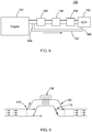
- FIG. 2 it shows a fluid control system 80 disposed in an upstream exhaust conduit 81.
- the upstream exhaust conduit 81 in one form defines a first flow channel 82 and a second flow channel 84 surrounding the first flow channel 82.
- the first flow channel 82 can be an inner flow channel and the second flow channel 84 an outer flow channel surrounding the first/inner flow channel 82.
- the second flow channel 84 is in fluid communication with the first flow channel 82.
- the first and second flow channels 82, 84 are in a fluid flow path of the exhaust system, such as the exhaust system of FIG. 1 .
- a heater 86 is disposed in the second flow channel 84.
- a fluid control device 88 is provided upstream of the first and second flow channel 82, 84 to control the flow path of the exhaust gas.
- the fluid control system 80 further includes an actuator 94 coupled to the fluid control device 88 and adapted to actuate the fluid control device 88 when the heater 86 is turned on.
- the fluid control device 88 may direct the exhaust gas through both the first and second flow channels 82, 84 during normal engine operation when the heater 86 is not activated.
- the fluid control device 88 is actuated when the heater 86 is turned on. Actuating the fluid control device 88 causes the first flow channel 82 to change a fluid flow rate in at least one of the first flow channel 82 and the second flow channel 84.
- Actuating the fluid control device 88 in one form causes fluid to flow through the second flow channel 84, in another form prevents fluid from flowing through the first flow channel 82 when fluid is flowing through both channels, and in another form partially re-directs a portion of the fluid flow through the second flow channel 84.
- the exhaust gas can be directed through only one of the first flow channel 82 and the second flow channel 84 during normal engine operation.
- the second flow channel 84 functions as a bypass channel.
- the heater 86 is not actuated, the exhaust gas is directed through only the first flow channel 82.
- the heater 86 is actuated, the exhaust gas is directed through only the second flow channel 84.
- a fluid control device 88 is provided upstream of the first and second flow channels 82, 84 to control the flow path of the exhaust gas.
- the flow control device 88 includes a flapper member 90, a support member 92.
- the support member 92 can be in the form of a bar extending from opposing ends of the flapper member 90 and the actuator 94.
- the flapper member 90 is disposed upstream from the first and second flow channels 82, 84.
- flapper member 90 defines a plate body having a position normal to the flow of exhaust gas.
- the heater 86 is not activated, the flapper member 90 is positioned such that the normal direction is perpendicular to the longitudinal axis of the first flow channels 82 and the exhaust gas is allowed to pass through the first flow channel 82.
- the flapper member 90 is positioned such that its normal direction is parallel to the longitudinal axis of the first flow channel 82 to close the first flow channel 82.
- the flow control device 88 is actuated to position the flapper member 90 in a different position based on the status of the heater 86 disposed in the second flow channel 84.
- the heater 86 is turned on to heat the exhaust gas flowing through the heater 36.
- the heat from the heater 86 causes the flow control device 88 to be actuated to direct the flow the exhaust gas through the second flow channel 84, thereby controlling the flow rate of the exhaust gas.
- the flow control device 88 may include one or more actuating surfaces 96 that can cause actuation of the flow control device 88 by thermal energy.
- the thermal energy can be provided through a number of sources, including by way of example, heat from the heater 86, a reaction to a change in temperature of the heater, the exhaust gas, a reaction to a change in temperature of the exhaust gas, differential thermal expansion, and combinations thereof.
- the actuating surface 96 faces the heater 86 and thus is heated.
- the flow control device 88 may include a flapper valve, butterfly valve, or a similar structure.
- the actuator 94 may include a material such as a shape memory alloy that changes shape in response to heat or temperature change.
- the flapper member 90 can be made of the shape memory alloys that change shape in response to a temperature or temperature change associated with heater operation.
- the flow control device 88 can change its position due to the changed shape of the flapper member 90.
- the flapper member 90 can be made of bi-metallic construction where a temperature associated with heater operation causes a displacement for actuating flow control device 88.
- the actuation of the flow control device 88 may be directly actuated by the actuating surface 96.
- the flow control device 100 includes a pivoting member 102 and an actuating member 104. As shown, the actuating member 104 is disposed proximate a wall of the first flow channel 82 and in contact with the heater 86.
- the pivoting member 102 is pivotably connected to the actuating member 104 and is pivotable to move between an open position A (where the first flow channel 82 is open) and a closed position B (where the first flow channel 82 is closed).
- the pivoting member 102 can further be operable to pivot and reduce fluid flow through first flow channel 82 by being positioned somewhere between a fully open and a fully closed position.
- the pivoting member 102 when the heater 86 is not actuated, the pivoting member 102 is in the open position to allow the exhaust gas to flow through the first flow channel 82.
- heat is applied to the actuating member 104 and causes the actuating member 104 to change its shape.
- the changed shape triggers the pivoting member 102 to move from the open position A to the closed position B or somewhere in between.
- the first flow channel 82 In a fully closed position B, the first flow channel 82 is closed thereby preventing fluid flow through the first flow channel 82 and opening the second flow channel 84 in which the heater 86 is disposed.
- the exhaust gas is directed through the second flow channel 84 and heated by the heater 86.
- a flow control device 120 includes multiple flexing members 122 that may be of a bi-metallic construction and mounted proximate a wall that defines the first flow channel 82 and positioned near the heater 86.
- the flexing members 122 are movable between an open position A (where the first flow channel 82 is open) and a closed position B (where the first flow channel 82 is closed). This includes various positions between position A and position B.
- the flexing members 122 can be in the open position A to open the first flow channel 82 and to block or reduce fluid flow through the second flow channel 84.
- the flexing members 122 change their shape and move toward each other to the closed positon B to close or reduce fluid flow through the first flow channel 82.
- the exhaust fluid is then directed through the second flow channel 84 and is heated by the heater 86 therein.
- the flow control device 120 is directly actuated by the operation of the heater 86 without using a separate actuator, such as a motor, solenoid, air cylinder or hydraulic cylinder, and associated control logic. Therefore, an opening through the exhaust pipe may not be needed in order to connect the flow control device 120 to an external actuator and thus leakage of exhaust gas through such an opening would not occur.
- the flow control device 120 of this form can reduce manufacturing costs and structural complexity.
- an engine system 150 includes a diesel engine 152, an exhaust aftertreatment system, including various exhaust treatment units 154, 156, 158, and an SCR 160.
- the various exhaust treatment units 154, 156, 158 may be any combination of a catalytic converter, a DPF, a DOC, an LNT, an ammonia slip catalyst, or reformers, depending on the application.
- the engine system 150 further includes a bypass conduit 162 coupled to the exhaust fluid flow having an inlet 164 disposed upstream of the various exhaust treatment units 154, 156, 158 and an outlet 166 disposed at a downstream of the various exhaust treatment units 154, 156, 158, which is also an inlet of the SCR 160.
- a heater 168 is provided in the bypass conduit 162.
- Flow control devices 170 as shown in FIGS. 2 to 7 are disposed at the inlet 164 and outlet 166 of the bypass conduit 162.
- the bypass conduit 162 is closed.
- the flow control devices 170 may open the inlet 164 of the bypass conduit 162 so that the exhaust gas is redirected through the bypass conduit 162 to be heated by the heater 168.
- the flow control device 170 positioned near the outlet 166 of the bypass conduit 162 may close the outlet 166 of the bypass conduit 162 to allow for the exhaust gas to be heated by the heater 168.
- bypass conduit 162 separate from the main exhaust path and by providing the heater 168 in the bypass conduit 162, the exhaust gas can more smoothly flow in the bypass conduit 162. Therefore, backpressure caused by the presence of the heater 168 in the main flow path as shown in FIGS. 2 to 7 can be reduced.
- the exhaust system 180 may include an exhaust aftertreatment system as shown in FIG. 8 , and a regeneration device including at least one valve 184 disposed downstream of an SCR 186 and a DPF 188.
- the regeneration device 182 may close an outlet of the exhaust pipe 182 downstream from the SCR 186. By closing the outlet, the exhaust gas remains in the DPF 188 and SCR 186 and increases the gas pressure inside the DPF 188 and the SCR 186. The increased pressure causes the temperature of the exhaust gas to increase, resulting in burning of the particles in the DPF 188 and facilitating SCR process in the SCR unit 186.
- a heater actuated mechanism may be employed that would change the position, orientation, angle of attack or other geometric characteristic of the heater to allow it to improve heat transfer when the heater is on and to allow it to shift into a position that reduces drag/backpressure when the heater is off.
- Such a mechanism may be attached directly to the heater or parts of the heater (e.g. a metal member attached directly to the heater surface that would move the heater by differential thermal expansion).
- Such a mechanism may include any of the fluid control devices and materials as disclosed herein, such as a shape memory alloy.
- each of the elements illustrated herein can be positioned or reconfigured such that they are aligned with the fluid flow rather than being arranged across the flow.
- another separate bypass could be employed to divert flow around the heater, similar to a piping system.
Landscapes
- Engineering & Computer Science (AREA)
- Chemical & Material Sciences (AREA)
- Combustion & Propulsion (AREA)
- Mechanical Engineering (AREA)
- General Engineering & Computer Science (AREA)
- Chemical Kinetics & Catalysis (AREA)
- Physics & Mathematics (AREA)
- General Physics & Mathematics (AREA)
- Automation & Control Theory (AREA)
- Health & Medical Sciences (AREA)
- Toxicology (AREA)
- Ceramic Engineering (AREA)
- Power Engineering (AREA)
- Fluid Mechanics (AREA)
- Analytical Chemistry (AREA)
- Exhaust Gas After Treatment (AREA)
- Control Of Resistance Heating (AREA)
- Processes For Solid Components From Exhaust (AREA)
- Measuring Volume Flow (AREA)
- Resistance Heating (AREA)
- Combined Controls Of Internal Combustion Engines (AREA)
- Measuring Temperature Or Quantity Of Heat (AREA)
- Investigating Or Analyzing Materials Using Thermal Means (AREA)
- Exhaust Gas Treatment By Means Of Catalyst (AREA)
- Physical Or Chemical Processes And Apparatus (AREA)
- Air-Conditioning For Vehicles (AREA)
Claims (9)
- Fluidsteuersystem (80), umfassend einen ersten Strömungskanal (82), einen zweiten Strömungskanal (84) in Fluidkommunikation mit dem ersten Strömungskanal (82) und
ein Heizelement (28, 86, 168), das in der Nähe mindestens eines von dem ersten Strömungskanal (82) und dem zweiten Strömungskanal (84) angeordnet ist;
eine Fluidsteuervorrichtung (88, 100, 120, 170), die stromaufwärts von dem ersten und zweiten Strömungskanal (82, 84) angeordnet ist, und
ein Betätigungselement (104, 122), das an die Fluidsteuervorrichtung gekoppelt ist und angepasst ist, eine Betätigung der Fluidsteuervorrichtung zu bewirken, wenn das Heizelement eingeschaltet wird, wobei das Betätigen der Fluidsteuervorrichtung eine Fluidströmungsrate in mindestens einem von dem ersten Strömungskanal (82) und dem zweiten Strömungskanal (84) ändert,
dadurch gekennzeichnet, dass
das Betätigungselement mittels Wärmeenergie angetrieben wird. - Fluidsteuersystem (80) nach Anspruch 1, wobei der erste Strömungskanal (82) ein innerer Strömungskanal ist und der zweite Strömungskanal (84, 162) ein äußerer Strömungskanal ist, der den inneren Strömungskanal umgibt.
- Fluidsteuersystem (80) nach Anspruch 1, wobei die Wärmeenergie von einer Quelle bereitgestellt wird, die ausgewählt wird aus der Gruppe, bestehend aus dem Heizelement, einer Reaktion auf eine Änderung in der Temperatur des Heizelements, dem Abgas, einer Reaktion auf eine Änderung in der Temperatur des Abgases, unterschiedlicher Wärmeausdehnung oder Kombinationen davon.
- Fluidsteuersystem (80) nach Anspruch 1, wobei die Fluidsteuervorrichtung (88, 100, 120, 170) ein Prallplattenelement (90) umfasst, das stromaufwärts von dem ersten und zweiten Strömungskanal (82, 84) angeordnet ist, wobei das Prallplattenelement (90) in Eingriff ist mit dem Betätigungselement (104, 122) und betriebsfähig, um die Fluidströmung zwischen dem ersten und zweiten Strömungskanal (82, 84) zu begrenzen, wenn es von dem Betätigungselement (104, 122) während einer Betätigung der Fluidsteuervorrichtung (88, 100, 120, 170) positioniert wird.
- Fluidsteuersystem (80) nach Anspruch 4, wobei das Prallplattenelement (90) einen Plattenkörper umfasst, der angepasst ist, seine Position als Antwort auf Hitze von dem Heizelement (28, 86, 168) zu ändern, um eine Fluidströmung durch den ersten Strömungskanal (82) zu begrenzen.
- Fluidsteuersystem (80) nach Anspruch 4, wobei die Fluidsteuervorrichtung (88, 100, 120, 170) mindestens eine Betätigungsoberfläche (96) umfasst, die auf dem Prallplattenelement (90) lagert, wobei die Betätigungsoberfläche (96), wenn sie von dem Heizelement erhitzt wird, betriebsfähig ist, zu bewirken, dass das Betätigungselement (104, 122) das Prallplattenelement (90) positioniert, um Fluidströmungen durch den zweiten Strömungskanal (84) zu bewirken.
- Fluidsteuersystem (80) nach Anspruch 4, wobei das Betätigungselement (104, 122) ein Material umfasst, das ausgewählt wird aus der Gruppe, bestehend aus einer Formgedächtnislegierung, einer Bimetallkonstruktion oder Kombinationen davon.
- Fluidsteuersystem (80) nach Anspruch 7, wobei die Fluidsteuervorrichtung (88, 100, 120, 170) angepasst ist, ihre Position zu ändern, wenn das Betätigungselement (104, 122) seine Form ändert, um eine Fluidströmung durch den ersten Strömungskanal (82) zu begrenzen.
- Fluidsteuersystem (80) nach Anspruch 1, wobei die Fluidsteuervorrichtung (88, 100, 120, 170) mindestens ein Schwenkelement (102) umfasst, das mit mindestens einem Betätigungselement (104, 122) schwenkbar verbunden ist, das in der Nähe einer Wand des ersten Strömungskanals (82) angeordnet ist, der nahe dem Heizelement (28, 86, 168) positioniert ist, wobei das mindestens eine Schwenkelement (102) betätigt wird, um eine Strömung durch den ersten Strömungskanal (82) zu begrenzen, wenn es von dem mindestens einem Betätigungselement (104, 122) betätigt wird, wenn das Heizelement (28, 86, 168) eingeschaltet wird.
Applications Claiming Priority (2)
| Application Number | Priority Date | Filing Date | Title |
|---|---|---|---|
| US201662302482P | 2016-03-02 | 2016-03-02 | |
| PCT/US2017/020516 WO2017151968A2 (en) | 2016-03-02 | 2017-03-02 | Heater-actuated flow bypass |
Publications (3)
| Publication Number | Publication Date |
|---|---|
| EP3423687A2 EP3423687A2 (de) | 2019-01-09 |
| EP3423687B1 true EP3423687B1 (de) | 2021-01-06 |
| EP3423687B8 EP3423687B8 (de) | 2021-03-17 |
Family
ID=58347961
Family Applications (10)
| Application Number | Title | Priority Date | Filing Date |
|---|---|---|---|
| EP17712884.0A Active EP3423684B1 (de) | 2016-03-02 | 2017-03-02 | System zur axialen unterteilung von heizleistung |
| EP17713803.9A Withdrawn EP3423689A1 (de) | 2016-03-02 | 2017-03-02 | Virtuelles abtastsystem |
| EP17711471.7A Active EP3423685B1 (de) | 2016-03-02 | 2017-03-02 | Fluidströmungsmesssystem und heizer mit doppelter funktion |
| EP17712292.6A Withdrawn EP3423683A1 (de) | 2016-03-02 | 2017-03-02 | Heizelement mit gezielten widerstandseigenschaften bei fallender temperatur |
| EP17712885.7A Active EP3423687B8 (de) | 2016-03-02 | 2017-03-02 | Wärmebetätigter strömungs-bypass |
| EP17711473.3A Withdrawn EP3423686A1 (de) | 2016-03-02 | 2017-03-02 | Wärmespeichervorrichtung zur verwendung in einem flüssigkeitsstromsystem |
| EP17712886.5A Withdrawn EP3423688A1 (de) | 2016-03-02 | 2017-03-02 | Suszeptor zum gebrauch in einem flüssigkeitsstromsystem |
| EP22150607.4A Pending EP4047193A1 (de) | 2016-03-02 | 2017-03-02 | Heizelement mit gezielten widerstandseigenschaften bei fallender temperatur |
| EP22153261.7A Pending EP4012164A1 (de) | 2016-03-02 | 2017-03-02 | Heizungssystem |
| EP17714046.4A Active EP3424265B1 (de) | 2016-03-02 | 2017-03-02 | Heizelement als sensor für die temperaturkontrolle in transienten systemen |
Family Applications Before (4)
| Application Number | Title | Priority Date | Filing Date |
|---|---|---|---|
| EP17712884.0A Active EP3423684B1 (de) | 2016-03-02 | 2017-03-02 | System zur axialen unterteilung von heizleistung |
| EP17713803.9A Withdrawn EP3423689A1 (de) | 2016-03-02 | 2017-03-02 | Virtuelles abtastsystem |
| EP17711471.7A Active EP3423685B1 (de) | 2016-03-02 | 2017-03-02 | Fluidströmungsmesssystem und heizer mit doppelter funktion |
| EP17712292.6A Withdrawn EP3423683A1 (de) | 2016-03-02 | 2017-03-02 | Heizelement mit gezielten widerstandseigenschaften bei fallender temperatur |
Family Applications After (5)
| Application Number | Title | Priority Date | Filing Date |
|---|---|---|---|
| EP17711473.3A Withdrawn EP3423686A1 (de) | 2016-03-02 | 2017-03-02 | Wärmespeichervorrichtung zur verwendung in einem flüssigkeitsstromsystem |
| EP17712886.5A Withdrawn EP3423688A1 (de) | 2016-03-02 | 2017-03-02 | Suszeptor zum gebrauch in einem flüssigkeitsstromsystem |
| EP22150607.4A Pending EP4047193A1 (de) | 2016-03-02 | 2017-03-02 | Heizelement mit gezielten widerstandseigenschaften bei fallender temperatur |
| EP22153261.7A Pending EP4012164A1 (de) | 2016-03-02 | 2017-03-02 | Heizungssystem |
| EP17714046.4A Active EP3424265B1 (de) | 2016-03-02 | 2017-03-02 | Heizelement als sensor für die temperaturkontrolle in transienten systemen |
Country Status (8)
| Country | Link |
|---|---|
| US (16) | US10648390B2 (de) |
| EP (10) | EP3423684B1 (de) |
| JP (9) | JP7091249B2 (de) |
| CN (8) | CN108925139B (de) |
| CA (7) | CA3016319C (de) |
| ES (3) | ES2847204T3 (de) |
| MX (8) | MX2018010596A (de) |
| WO (8) | WO2017151960A1 (de) |
Families Citing this family (47)
| Publication number | Priority date | Publication date | Assignee | Title |
|---|---|---|---|---|
| DE102014008284A1 (de) * | 2014-06-03 | 2015-12-03 | Diehl Metering Gmbh | Verfahren zur Bestimmung des Volumenflusses eines strömenden Mediums durch eine Messstrecke und zugeordnete Messeinrichtung |
| EP3153379B1 (de) * | 2014-06-06 | 2019-11-06 | Panasonic Intellectual Property Management Co., Ltd. | Elektrostatische griffdetektionsvorrichtung |
| EP3423684B1 (de) * | 2016-03-02 | 2020-05-06 | Watlow Electric Manufacturing Company | System zur axialen unterteilung von heizleistung |
| US11255244B2 (en) | 2016-03-02 | 2022-02-22 | Watlow Electric Manufacturing Company | Virtual sensing system |
| CN109893941A (zh) * | 2017-12-07 | 2019-06-18 | 南京苏曼等离子科技有限公司 | 一种低温等离子体尘雾毒废气处理系统 |
| US10557428B2 (en) * | 2018-05-25 | 2020-02-11 | GM Global Technology Operations LLC | Method and system for predictive contol of an electrially heated aftertreatment system |
| FR3081921B1 (fr) * | 2018-05-29 | 2020-12-18 | Psa Automobiles Sa | Ligne d’echappement de moteur thermique comprenant un element de chauffage amont |
| JP7070246B2 (ja) * | 2018-08-27 | 2022-05-18 | オムロン株式会社 | 電熱体種判別装置、電熱体種判別方法、およびプログラム |
| JP7081392B2 (ja) * | 2018-08-27 | 2022-06-07 | オムロン株式会社 | 温度警報システム、温度警報方法、及びプログラム |
| DE102018217169B4 (de) * | 2018-10-08 | 2021-12-23 | Vitesco Technologies GmbH | Energieoptimale erzwungene Regeneration eines Partikelfilters eines Hybridfahrzeugs |
| US10669908B1 (en) | 2018-12-03 | 2020-06-02 | Wellhead Power Solutions, Llc | Power generating systems and methods for reducing startup NOx emissions in fossile fueled power generation system |
| WO2020159991A1 (en) * | 2019-01-29 | 2020-08-06 | Watlow Electric Manufacturing Company | Virtual sensing system |
| JP7034376B2 (ja) * | 2019-03-22 | 2022-03-11 | 日本碍子株式会社 | ハニカム構造体及び排気ガス浄化装置 |
| GB2619428B (en) * | 2019-05-09 | 2024-04-03 | Cummins Emission Solutions Inc | Valve arrangement for split-flow close-coupled catalyst |
| DE112019007304T5 (de) | 2019-05-09 | 2022-02-17 | Cummins Emission Solutions Inc. | Ventilanordnung für split-flow-katalysator in eng gekoppelter bauweise |
| EP3808235B1 (de) * | 2019-10-15 | 2023-02-01 | Vorwerk & Co. Interholding GmbH | Verfahren zum betreiben eines heizsystems und küchenmaschine |
| CN110793777B (zh) * | 2019-10-23 | 2021-05-25 | 清华大学 | 一种模拟柴油机进气道环境进气预热效果的测试装置 |
| EP3843501B1 (de) * | 2019-12-23 | 2022-10-19 | Kanthal GmbH | Verfahren und systeme zur kühlung eines heizelements |
| DE102020101194B4 (de) | 2020-01-20 | 2022-07-28 | Volkswagen Aktiengesellschaft | Verfahren zur Abgasnachbehandlung eines Verbrennungsmotors sowie Verbrennungsmotor |
| EP4197287A1 (de) * | 2020-08-12 | 2023-06-21 | Watlow Electric Manufacturing Company | Verfahren und system zur bereitstellung einer variablen herunterfahrsteuerung für ein elektrisches heizelement |
| CN112197826A (zh) * | 2020-09-02 | 2021-01-08 | 中国空气动力研究与发展中心低速空气动力研究所 | 一种航空发动机进气质量流量测量装置及测量方法 |
| US11668488B2 (en) | 2020-09-11 | 2023-06-06 | Rheem Manufacturing Company | System and method of controlling a heat transfer system |
| CN112414911B (zh) * | 2020-09-27 | 2021-08-24 | 清华大学 | 一种燃气轮机进气过滤系统运行状态实时监测方法 |
| CN112747929B (zh) * | 2020-11-30 | 2021-11-23 | 南京航空航天大学 | 一种扩大叶栅攻角调节范围的叶栅试验台流道调节机构 |
| KR20230132824A (ko) | 2021-01-19 | 2023-09-18 | 와틀로 일렉트릭 매뉴팩츄어링 컴파니 | 산업 시스템들에 대한 유체 라인 누출을 검출하고 진단하기위한 방법 및 시스템 |
| DE102021200701A1 (de) | 2021-01-27 | 2022-07-28 | Robert Bosch Gesellschaft mit beschränkter Haftung | Verfahren und Vorrichtung zur Diagnose eines Katalysators mit einem elektrischen Heizer |
| CN113056044B (zh) * | 2021-03-10 | 2022-11-25 | 刘忠海 | 一种石墨烯金属网及其制备方法以及电加热带及其应用 |
| CN112963225B (zh) * | 2021-03-25 | 2023-02-17 | 一汽解放汽车有限公司 | 尾气加热装置及尾气处理系统 |
| CN113513652A (zh) * | 2021-04-14 | 2021-10-19 | 西安热工研究院有限公司 | 一种工业篮式管道加热装置及其加热方法 |
| DE102021109567A1 (de) * | 2021-04-16 | 2022-10-20 | Purem GmbH | Heizleiter für eine Abgasheizanordnung |
| US20220364488A1 (en) * | 2021-05-16 | 2022-11-17 | Eaton Intelligent Power Limited | Aftertreatment heater power electronics |
| DE102021113989A1 (de) | 2021-05-31 | 2022-12-01 | Purem GmbH | Abgasheizer |
| EP4098853A1 (de) * | 2021-06-01 | 2022-12-07 | Volvo Truck Corporation | Abgasnachbehandlungssystem |
| US20220388514A1 (en) * | 2021-06-02 | 2022-12-08 | Cummins Inc. | Systems and methods for reducing emissions with smart alternator |
| DE102022206430A1 (de) | 2021-06-29 | 2022-12-29 | Cummins Emission Solutions Inc. | Systeme und Verfahren zur Reduzierung der NOx-Emissionen von Nachbehandlungssystemen |
| DE102021122083A1 (de) * | 2021-08-26 | 2023-03-02 | Purem GmbH | Abgasheizer |
| DE102021210761A1 (de) | 2021-09-27 | 2023-03-30 | Vitesco Technologies GmbH | Heizleiter zur Aufheizung eines Abgasstroms einer Verbrennungskraftmaschine |
| CA3238681A1 (en) | 2021-11-22 | 2023-05-25 | Watlow Electric Manufacturing Company | Method of generating a digital twin of the environment of industrial processes |
| DE102022100696A1 (de) * | 2022-01-13 | 2023-07-13 | Bayerische Motoren Werke Aktiengesellschaft | Verfahren und Steuergerät zum Betreiben eines Dieselkraftfahrzeugs zur Emissionsreduzierung und Kraftfahrzeug |
| CN114486622B (zh) * | 2022-01-19 | 2023-10-20 | 山东交通学院 | 一种实时测量液体在不同温度下密度的实验装置及方法 |
| CN114323568B (zh) * | 2022-03-14 | 2022-07-08 | 武汉普赛斯电子技术有限公司 | 光器件的三温测试系统 |
| KR20230144270A (ko) * | 2022-04-07 | 2023-10-16 | 한온시스템 주식회사 | 유체가열 히터 및 유체가열 히터의 구동제어방법 |
| CN114856843B (zh) * | 2022-05-18 | 2023-05-23 | 潍柴动力股份有限公司 | 一种排气量计算方法、egr气量控制方法及egr系统 |
| US11828796B1 (en) | 2023-05-02 | 2023-11-28 | AEM Holdings Ltd. | Integrated heater and temperature measurement |
| US12013432B1 (en) | 2023-08-23 | 2024-06-18 | Aem Singapore Pte. Ltd. | Thermal control wafer with integrated heating-sensing elements |
| US12085609B1 (en) | 2023-08-23 | 2024-09-10 | Aem Singapore Pte. Ltd. | Thermal control wafer with integrated heating-sensing elements |
| US12000885B1 (en) | 2023-12-20 | 2024-06-04 | Aem Singapore Pte. Ltd. | Multiplexed thermal control wafer and coldplate |
Family Cites Families (246)
| Publication number | Priority date | Publication date | Assignee | Title |
|---|---|---|---|---|
| US1366519A (en) * | 1920-03-13 | 1921-01-25 | Samuel M Carmean | Electric heater |
| US1467810A (en) | 1921-10-25 | 1923-09-11 | Westinghouse Electric & Mfg Co | High-temperature resistor material |
| US1791561A (en) | 1929-05-03 | 1931-02-10 | Surface Combustion Corp | Apparatus for heating air |
| US2091905A (en) * | 1935-09-09 | 1937-08-31 | Bensel Arlington | Electric resistance heating element |
| US2900483A (en) * | 1958-09-29 | 1959-08-18 | Gen Electric | Electric catalytic contact device |
| US3037942A (en) * | 1959-11-02 | 1962-06-05 | Gen Electric | Positive temperature coefficient of resistivity resistor |
| US3176117A (en) * | 1961-03-09 | 1965-03-30 | Berko Electric Mfg Corp | Electric space heater unit |
| US3231522A (en) | 1963-09-26 | 1966-01-25 | American Radiator & Standard | Thermistor |
| US3694626A (en) * | 1971-09-30 | 1972-09-26 | Gen Electric | Electrical resistance heater |
| US4211075A (en) * | 1978-10-19 | 1980-07-08 | General Motors Corporation | Diesel engine exhaust particulate filter with intake throttling incineration control |
| JPS6032334Y2 (ja) * | 1979-12-21 | 1985-09-27 | トヨタ自動車株式会社 | 内燃機関の排気ガス中の微粒子捕集装置 |
| FR2481507A1 (fr) | 1980-04-29 | 1981-10-30 | Stein Industrie | Dispositif de reduction des contraintes thermiques dans le fond d'un echangeur de chaleur vertical |
| JPS5728214A (en) * | 1980-07-28 | 1982-02-15 | Nippon Soken Inc | Gas flow rate measuring device |
| JPS5823187A (ja) * | 1981-08-03 | 1983-02-10 | 株式会社日本自動車部品総合研究所 | セラミツク構造体およびその製造方法 |
| US4449362A (en) * | 1981-12-02 | 1984-05-22 | Robertshaw Controls Company | Exhaust system for an internal combustion engine, burn-off unit and methods therefor |
| JPS59192928A (ja) * | 1983-04-15 | 1984-11-01 | Hitachi Ltd | 薄膜最高温度計 |
| JPS6184563A (ja) | 1984-10-02 | 1986-04-30 | Honda Kogyo Kk | 流体速度測定方法及びその装置 |
| DE3579427D1 (de) * | 1984-12-26 | 1990-10-04 | Nippon Denso Co | Reduktionswiderstandsfaehiges halbleiterporzellan mit positivem temperaturkoeffizienten des widerstandes. |
| DE3538155A1 (de) * | 1985-10-26 | 1987-04-30 | Fev Forsch Energietech Verbr | Verfahren zur oxidation von in russfiltersystemen abgelagerten partikeln |
| US4808009A (en) * | 1986-06-05 | 1989-02-28 | Rosemount, Inc. | Integrated semiconductor resistance temperature sensor and resistive heater |
| US4814587A (en) * | 1986-06-10 | 1989-03-21 | Metcal, Inc. | High power self-regulating heater |
| US4744216A (en) * | 1986-10-20 | 1988-05-17 | Ford Motor Company | Electrical ignition device for regeneration of a particulate trap |
| JPH0816030B2 (ja) * | 1986-12-08 | 1996-02-21 | 日本電装株式会社 | 窒化珪素−窒化チタン系複合導電材料 |
| JPH01143202A (ja) * | 1987-11-28 | 1989-06-05 | Central Glass Co Ltd | 中高温用ptcサーミスタ |
| US5319929A (en) | 1988-05-20 | 1994-06-14 | W. R. Grace & Co.-Conn. | Catalytic converter system |
| US4878928A (en) * | 1988-07-28 | 1989-11-07 | Donaldson Company, Inc. | Apparatus for increasing regenerative filter heating element temperature |
| DE8810816U1 (de) | 1988-08-26 | 1989-12-21 | Emitec Gesellschaft für Emissionstechnologie mbH, 53797 Lohmar | Katalysator-Gehäuse, insbesondere für Startkatalysatoren, und zugehöriger Katalysator-Trägerkörper |
| JPH07118369B2 (ja) * | 1988-11-09 | 1995-12-18 | 憲親 武部 | 自己温度制御性ヒータ |
| GB2228396A (en) | 1989-02-20 | 1990-08-22 | Emaco | Electric hotplate |
| JPH04219413A (ja) | 1990-02-20 | 1992-08-10 | W R Grace & Co | 内燃機関の排気系 |
| EP0456919A3 (en) | 1990-04-16 | 1992-01-22 | W.R. Grace & Co.-Conn. | Catalytic converter system |
| US5373033A (en) | 1990-04-20 | 1994-12-13 | Sola International Holdings Limited | Casting composition |
| JPH086268Y2 (ja) * | 1990-06-15 | 1996-02-21 | オーバル機器工業株式会社 | 熱式流量計 |
| US5280422A (en) | 1990-11-05 | 1994-01-18 | Watlow/Winona, Inc. | Method and apparatus for calibrating and controlling multiple heaters |
| GB2255988B (en) | 1991-05-23 | 1994-12-07 | Feng Ping Jan | Furniture for use as a safe haven during earthquakes |
| DE4122141C2 (de) | 1991-07-04 | 1999-05-27 | Porsche Ag | Abgasleitung einer Brennkraftmaschine |
| US5259190A (en) * | 1991-08-01 | 1993-11-09 | Corning Incorporated | Heated cellular structures |
| US5393499A (en) * | 1992-06-03 | 1995-02-28 | Corning Incorporated | Heated cellular substrates |
| US5233970A (en) | 1992-07-02 | 1993-08-10 | Harmony Thermal Company, Inc. | Semi-instantaneous water heater with helical heat exchanger |
| US5465573A (en) * | 1992-07-29 | 1995-11-14 | Ngk Insulators, Ltd. | Multi-stage honeycomb heater |
| JP3058991B2 (ja) * | 1992-07-29 | 2000-07-04 | 日本碍子株式会社 | 多段ハニカムヒーターおよびその運転方法 |
| US5297518A (en) * | 1992-08-10 | 1994-03-29 | Cherry Mark A | Mass controlled compression timed ignition method and igniter |
| DE4328125B4 (de) * | 1992-08-21 | 2004-03-18 | Denso Corp., Kariya | Abgasreinigungsvorrichtung für einen Verbrennungsmotor oder dergleichen |
| US5582805A (en) * | 1992-12-21 | 1996-12-10 | Toyota Jidosha Kabushiki Kaisha | Electrically heated catalytic apparatus |
| US5444217A (en) | 1993-01-21 | 1995-08-22 | Moore Epitaxial Inc. | Rapid thermal processing apparatus for processing semiconductor wafers |
| JP3396247B2 (ja) * | 1993-02-15 | 2003-04-14 | 三菱重工業株式会社 | 排気ガス浄化装置 |
| US5738832A (en) * | 1993-02-15 | 1998-04-14 | Mitsubishi Jidosha Kogyo Kabushiki Kaisha | Exhaust gas purifying apparatus |
| US5471034A (en) * | 1993-03-17 | 1995-11-28 | Texas Instruments Incorporated | Heater apparatus and process for heating a fluid stream with PTC heating elements electrically connected in series |
| US5310327A (en) | 1993-03-29 | 1994-05-10 | Reginald Phillips | Workpiece deflector shield for an injection molding apparatus |
| JPH06336915A (ja) | 1993-05-31 | 1994-12-06 | Nissan Motor Co Ltd | 内燃機関の排気浄化装置 |
| US5716586A (en) * | 1993-06-03 | 1998-02-10 | Kabushiki Kaisha Toyoda Jidoshokki Seisakusho | Exhaust gas purifier |
| JPH0711946A (ja) * | 1993-06-29 | 1995-01-13 | Nissan Motor Co Ltd | 内燃機関の排気浄化装置 |
| JPH0754640A (ja) * | 1993-08-12 | 1995-02-28 | Mitsubishi Motors Corp | 排気浄化装置 |
| DE4339290C2 (de) * | 1993-11-18 | 1995-11-02 | Daimler Benz Ag | Verfahren zum Herstellen von Rohr-T-Stücken aus einem unverzweigt durchgehenden Ausgangsrohrstück durch Innenhochdruck-Umformung sowie Vorrichtung zur Durchführung des Verfahrens |
| JP2732031B2 (ja) * | 1994-04-28 | 1998-03-25 | 株式会社いすゞセラミックス研究所 | デイーゼル機関の排気微粒子フイルタ |
| US5582003A (en) * | 1994-04-28 | 1996-12-10 | Corning Incorporated | Temperature actuated zeolite in-line adsorber system |
| DE69502344T2 (de) * | 1994-05-17 | 1998-11-19 | Isuzu Ceramics Res Inst | Dieselpartikelfilter |
| JP3524956B2 (ja) | 1994-05-30 | 2004-05-10 | トヨタ自動車株式会社 | 電気加熱式触媒装置 |
| US5444976A (en) | 1994-06-27 | 1995-08-29 | General Motors Corporation | Catalytic converter heating |
| US5603216A (en) * | 1994-08-02 | 1997-02-18 | Corning Incorporated | By-pass adsorber system |
| JP3553146B2 (ja) * | 1994-08-22 | 2004-08-11 | 本田技研工業株式会社 | 電気加熱式触媒制御装置 |
| US5651248A (en) * | 1994-08-29 | 1997-07-29 | Isuzu Ceramics Research Institute Co., Ltd. | Diesel particulate filter apparatus |
| US5620490A (en) * | 1994-08-29 | 1997-04-15 | Isuzu Ceramics Research Institute Co., Ltd. | Diesel particulate filter apparatus |
| JPH0868311A (ja) * | 1994-08-29 | 1996-03-12 | Isuzu Ceramics Kenkyusho:Kk | ディーゼルパティキュレートフィルタの構造 |
| JPH0868310A (ja) * | 1994-08-29 | 1996-03-12 | Isuzu Ceramics Kenkyusho:Kk | ディーゼルパティキュレートフィルタ装置 |
| JPH08122118A (ja) | 1994-10-20 | 1996-05-17 | Tokyo Gas Co Ltd | 熱式マイクロフローセンサ |
| US5611831A (en) * | 1994-11-16 | 1997-03-18 | Isuzu Ceramics Research Institute Co., Ltd. | Diesel particulate filter apparatus |
| JPH08193513A (ja) * | 1995-01-13 | 1996-07-30 | Calsonic Corp | 電気加熱触媒コンバータおよびその制御方法 |
| US5716133A (en) | 1995-01-17 | 1998-02-10 | Applied Komatsu Technology, Inc. | Shielded heat sensor for measuring temperature |
| JPH08284652A (ja) * | 1995-04-18 | 1996-10-29 | Toyota Motor Corp | 電気加熱式触媒の構造 |
| US5597503A (en) * | 1995-06-02 | 1997-01-28 | Corning Incorporated | Axially assembled enclosure for electrical fluid heater having a peripheral compression ring producing a diametrically balanced force |
| US5600947A (en) | 1995-07-05 | 1997-02-11 | Ford Motor Company | Method and system for estimating and controlling electrically heated catalyst temperature |
| IL118739A0 (en) | 1995-09-07 | 1996-10-16 | Bar Keser Project Management I | Electric heating devices and heating elements for use therewith |
| US6704497B2 (en) | 1995-09-07 | 2004-03-09 | Bar-Keser Project Management Initiatives And Economic Consultants (1991) Ltd. | Electric heating devices and elements |
| JPH09180907A (ja) * | 1995-10-27 | 1997-07-11 | Murata Mfg Co Ltd | 積層複合セラミックとそれを用いた積層複合セラミック素子 |
| JPH09158717A (ja) * | 1995-12-08 | 1997-06-17 | Toyota Motor Corp | 電気加熱式触媒の電力供給制御装置 |
| DE69728256T2 (de) | 1996-01-31 | 2005-03-03 | Asm America Inc., Phoenix | Modellgestützte prädiktive regelung für thermische behandlungen |
| FR2755623B1 (fr) | 1996-11-12 | 1998-12-04 | Inst Francais Du Petrole | Procede et unite de filtration de gaz d'echappement, ayant un chauffage modulable |
| US5719378A (en) * | 1996-11-19 | 1998-02-17 | Illinois Tool Works, Inc. | Self-calibrating temperature controller |
| JPH10184346A (ja) * | 1996-12-27 | 1998-07-14 | Nissan Motor Co Ltd | 内燃機関の排気浄化装置 |
| CN1047457C (zh) * | 1997-02-26 | 1999-12-15 | 清华大学 | 中低温烧结复合特性热敏电阻材料及其制备方法 |
| JP3365244B2 (ja) * | 1997-03-06 | 2003-01-08 | 松下電器産業株式会社 | 排ガス浄化装置 |
| JPH10259709A (ja) * | 1997-03-19 | 1998-09-29 | Matsushita Electric Ind Co Ltd | 排ガス浄化方法及び排ガス浄化装置 |
| DE19720205B4 (de) | 1997-05-14 | 2006-05-18 | Johannes Schedler | Anlage zur Reinigung von mit Stickoxiden beladenen Abgasen |
| JP3269012B2 (ja) | 1997-08-19 | 2002-03-25 | 株式会社椿本チエイン | モータ付減速機の減速主軸の軸方向取付け調整装置 |
| JP3331919B2 (ja) * | 1997-08-29 | 2002-10-07 | 三菱自動車工業株式会社 | 内燃機関の排気ガス浄化装置 |
| CA2310635C (en) * | 1997-11-21 | 2005-01-18 | Mitsui Mining & Smelting Co., Ltd. | Flow rate sensor, temperature sensor and flow rate measuring instrument |
| JPH11184346A (ja) | 1997-12-25 | 1999-07-09 | Copyer Co Ltd | 画像形成装置及び紙綴じ装置 |
| JP3658170B2 (ja) * | 1998-01-19 | 2005-06-08 | 三菱電機株式会社 | 流量センサ |
| JP2957163B1 (ja) * | 1998-05-28 | 1999-10-04 | 株式会社三五 | 排気系部品とその製造方法 |
| JP2000007301A (ja) * | 1998-06-29 | 2000-01-11 | Ngk Insulators Ltd | 改質反応装置 |
| US6330910B1 (en) | 1999-03-03 | 2001-12-18 | Easton Bennett | Heat exchanger for a motor vehicle exhaust |
| US6474155B1 (en) | 1999-07-08 | 2002-11-05 | Lockheed Martin Corporation | Constant-temperature-difference flow sensor |
| US7624632B1 (en) * | 1999-08-17 | 2009-12-01 | Lockheed Martin Corporation | Constant-temperature-difference flow sensor, and integrated flow, temperature, and pressure sensor |
| US6470741B1 (en) * | 2000-06-23 | 2002-10-29 | Instrumentarium, Inc. | Hot wire anemometer gas flow sensor having improved operation and compensation |
| JP4239417B2 (ja) | 2000-07-10 | 2009-03-18 | トヨタ自動車株式会社 | 蓄熱装置付き内燃機関 |
| JP2002070531A (ja) | 2000-08-24 | 2002-03-08 | Ibiden Co Ltd | 排気ガス浄化装置、排気ガス浄化装置のケーシング構造 |
| GB2374783A (en) | 2000-12-15 | 2002-10-23 | Jeffery Boardman | Self regulating heating element |
| US6622558B2 (en) | 2000-11-30 | 2003-09-23 | Orbital Research Inc. | Method and sensor for detecting strain using shape memory alloys |
| JP2002227640A (ja) * | 2001-02-02 | 2002-08-14 | Sankei Kogyo Kk | 排気ガス浄化装置 |
| US6396028B1 (en) | 2001-03-08 | 2002-05-28 | Stephen J. Radmacher | Multi-layer ceramic heater |
| US6951099B2 (en) | 2001-04-03 | 2005-10-04 | John Dickau | Heated insulated catalytic converter with air cooling |
| JP3941427B2 (ja) * | 2001-07-16 | 2007-07-04 | 株式会社Sumco | 加熱装置及び加熱方法 |
| NZ532091A (en) | 2001-10-24 | 2005-12-23 | Shell Int Research | In situ recovery from a hydrocarbon containing formation using barriers |
| JP3748063B2 (ja) * | 2001-10-29 | 2006-02-22 | 三菱自動車工業株式会社 | 排圧上昇装置 |
| JP3824959B2 (ja) * | 2002-03-29 | 2006-09-20 | 本田技研工業株式会社 | 排ガスセンサの温度制御装置 |
| JP3538188B2 (ja) * | 2002-04-02 | 2004-06-14 | 三菱電機株式会社 | 感熱式流量検出素子およびその製造方法 |
| US6882929B2 (en) | 2002-05-15 | 2005-04-19 | Caterpillar Inc | NOx emission-control system using a virtual sensor |
| DE10225337A1 (de) * | 2002-06-06 | 2003-12-24 | Schott Glas | Kochsystem mit direkt geheizter Glaskeramikplatte |
| US7106167B2 (en) * | 2002-06-28 | 2006-09-12 | Heetronix | Stable high temperature sensor system with tungsten on AlN |
| JP4503222B2 (ja) * | 2002-08-08 | 2010-07-14 | 本田技研工業株式会社 | 内燃機関の空燃比制御装置 |
| ATE342069T1 (de) * | 2002-08-30 | 2006-11-15 | Dial Corp | Verfahren und gerät für einen variablen resistor zur kompensierung von nichtlinearitäten in einem heizelementkreislauf |
| EP1416143A1 (de) | 2002-10-29 | 2004-05-06 | STMicroelectronics S.r.l. | Virtueller Sensor für die Abgasemission einer Brennkraftmaschine und das Einspritzsteuersystem |
| DE10300298A1 (de) * | 2003-01-02 | 2004-07-15 | Daimlerchrysler Ag | Abgasnachbehandlungseinrichtung und -verfahren |
| US7049558B2 (en) | 2003-01-27 | 2006-05-23 | Arcturas Bioscience, Inc. | Apparatus and method for heating microfluidic volumes and moving fluids |
| FR2851404A1 (fr) * | 2003-02-18 | 2004-08-20 | Acome Soc Coop Travailleurs | Dispositif a cable chauffant ctp comprenant un dispositif de limitation de courant |
| JP2005001449A (ja) | 2003-06-10 | 2005-01-06 | Denso Corp | 車両用冷凍サイクル装置 |
| US7196295B2 (en) | 2003-11-21 | 2007-03-27 | Watlow Electric Manufacturing Company | Two-wire layered heater system |
| US7101816B2 (en) | 2003-12-29 | 2006-09-05 | Tokyo Electron Limited | Methods for adaptive real time control of a thermal processing system |
| EP1738052B1 (de) * | 2004-04-23 | 2008-04-16 | Shell International Research Maatschappij B.V. | Verhinderung von rücklauf in einer beheizten senkung eines in-situ-umwandlungssystems |
| US7403704B2 (en) | 2004-08-06 | 2008-07-22 | Terumo Cardiovascular Systems Corporation | Dual heating device and method |
| JP4186899B2 (ja) * | 2004-09-30 | 2008-11-26 | 株式会社日立製作所 | 排気還流制御装置 |
| US7143580B2 (en) | 2004-10-22 | 2006-12-05 | Detroit Diesel Corporation | Virtual compressor outlet temperature sensing for charge air cooler overheating protection |
| DE102004052107B4 (de) | 2004-10-26 | 2007-03-15 | J. Eberspächer GmbH & Co. KG | Abgasanlage und zugehöriges Betriebsverfahren |
| KR100611606B1 (ko) * | 2004-11-15 | 2006-08-10 | 한국전기연구원 | 마이크로파 반사기를 이용한 디젤 매연 필터 시스템 |
| US20060177358A1 (en) * | 2005-02-07 | 2006-08-10 | Tzong-Yih Lee | Active catalytic converter |
| JP2008530446A (ja) | 2005-02-16 | 2008-08-07 | アイエムアイ・ビジョン・リミテッド | 排気ガス処理 |
| US7251929B2 (en) | 2005-07-07 | 2007-08-07 | Eaton Corporation | Thermal management of hybrid LNT/SCR aftertreatment during desulfation |
| US7495467B2 (en) | 2005-12-15 | 2009-02-24 | Lattice Semiconductor Corporation | Temperature-independent, linear on-chip termination resistance |
| US7243538B1 (en) * | 2005-12-22 | 2007-07-17 | Honeywell International Inc. | Gas flow sensor system and method of self-calibration |
| WO2007105815A1 (en) * | 2006-03-16 | 2007-09-20 | Toyota Jidosha Kabushiki Kaisha | Exhaust gas heat recovery device |
| CN101410597B (zh) | 2006-03-30 | 2011-07-27 | 株式会社Ict | 内燃机废气净化方法 |
| US8117832B2 (en) * | 2006-06-19 | 2012-02-21 | Donaldson Company, Inc. | Exhaust treatment device with electric regeneration system |
| JP4535036B2 (ja) * | 2006-07-12 | 2010-09-01 | トヨタ自動車株式会社 | 内燃機関の電源システム |
| DE102006032698A1 (de) * | 2006-07-14 | 2008-01-24 | Bleckmann Gmbh & Co. Kg | Vorrichtung und Verfahren zur Steuerung und Absicherung eines Heizelements |
| US8209960B2 (en) | 2006-07-21 | 2012-07-03 | International Engine Intellectual Property Company, Llc | System and method for coupled DPF regeneration and LNT DeNOx |
| US7434387B2 (en) | 2006-07-26 | 2008-10-14 | Eaton Corporation | Integrated DPF-reformer |
| JP4341651B2 (ja) * | 2006-07-28 | 2009-10-07 | 株式会社日立製作所 | 熱式ガス流量計 |
| US8762097B2 (en) | 2006-08-04 | 2014-06-24 | Apple Inc. | Method and apparatus for a thermal control system based on virtual temperature sensor |
| JP2008038827A (ja) * | 2006-08-09 | 2008-02-21 | Calsonic Kansei Corp | エンジン即暖システムの制御方法 |
| US7554063B2 (en) * | 2006-08-22 | 2009-06-30 | Dimplex North America Limited | Heating apparatus |
| US7631491B2 (en) | 2006-11-15 | 2009-12-15 | Detroit Diesel Corporation | Method and system for passive regeneration of compression ignition engine exhaust filters |
| GB0700079D0 (en) | 2007-01-04 | 2007-02-07 | Boardman Jeffrey | A method of producing electrical resistance elements whihc have self-regulating power output characteristics by virtue of their configuration and the material |
| JP2008180185A (ja) * | 2007-01-26 | 2008-08-07 | Hitachi Ltd | エンジンの排気還流制御装置 |
| US7757482B2 (en) * | 2007-02-21 | 2010-07-20 | Gm Global Technology Operations, Inc. | Variable geometry exhaust cooler |
| WO2008115356A1 (en) | 2007-03-22 | 2008-09-25 | Exxonmobil Upstream Research Company | Resistive heater for in situ formation heating |
| DE102007025419A1 (de) | 2007-05-31 | 2008-12-04 | Emitec Gesellschaft Für Emissionstechnologie Mbh | Verfahren zum Betrieb eines Kraftfahrzeuges mit einer Abgas-Heizvorrichtung |
| US8037673B2 (en) | 2007-06-18 | 2011-10-18 | GM Global Technology Operations LLC | Selective catalyst reduction light-off strategy |
| JP2009058501A (ja) * | 2007-08-08 | 2009-03-19 | Yamaha Motor Co Ltd | ガスセンサ、空燃比制御装置および輸送機器 |
| US8057581B2 (en) * | 2007-08-31 | 2011-11-15 | GM Global Technology Operations LLC | Zoned electrical heater arranged in spaced relationship from particulate filter |
| US8083839B2 (en) * | 2007-09-13 | 2011-12-27 | GM Global Technology Operations LLC | Radiant zone heated particulate filter |
| US8112990B2 (en) | 2007-09-14 | 2012-02-14 | GM Global Technology Operations LLC | Low exhaust temperature electrically heated particulate matter filter system |
| US8252077B2 (en) * | 2007-09-17 | 2012-08-28 | GM Global Technology Operations LLC | Electrically heated particulate filter heater insulation |
| US8292987B2 (en) | 2007-09-18 | 2012-10-23 | GM Global Technology Operations LLC | Inductively heated particulate matter filter regeneration control system |
| JP5210588B2 (ja) * | 2007-10-03 | 2013-06-12 | 日立オートモティブシステムズ株式会社 | 熱式流量計、熱式流量計の制御方法、及び熱式流量計のセンサ素子 |
| US8146350B2 (en) | 2007-10-04 | 2012-04-03 | GM Global Technology Operations LLC | Variable power distribution for zoned regeneration of an electrically heated particulate filter |
| US8061123B2 (en) * | 2007-10-30 | 2011-11-22 | Caterpillar Inc. | Method and system of thermal management in an exhaust system |
| US20090205588A1 (en) * | 2008-02-15 | 2009-08-20 | Bilezikjian John P | Internal combustion engine with variable speed coolant pump |
| JP5004842B2 (ja) * | 2008-03-25 | 2012-08-22 | 三井造船株式会社 | 誘導加熱装置 |
| EP2106195B1 (de) * | 2008-03-28 | 2010-05-05 | Braun GmbH | Heizelement mit Temperatursensor |
| JP2009236792A (ja) | 2008-03-28 | 2009-10-15 | Hitachi Ltd | 熱式ガス流量計 |
| GB2460833B (en) * | 2008-06-09 | 2011-05-18 | 2D Heat Ltd | A self-regulating electrical resistance heating element |
| US8121744B2 (en) * | 2008-06-20 | 2012-02-21 | GM Global Technology Operations LLC | Control system and method for oxygen sensor heater control |
| JP2010025104A (ja) | 2008-07-16 | 2010-02-04 | Borgwarner Inc | 後処理装置の受動的暖機制御用熱操作バイパス弁 |
| US8112989B1 (en) * | 2008-07-23 | 2012-02-14 | Hrl Laboratories, Llc | Electrically resistive coating for remediation (regeneration) of a diesel particulate filter and method |
| DE102008035562A1 (de) | 2008-07-30 | 2010-02-04 | Emitec Gesellschaft Für Emissionstechnologie Mbh | Abgasreinigungssystem für Dieselmotoren von Nutzkraftfahrzeugen |
| CN102149904B (zh) * | 2008-09-10 | 2014-01-29 | 马克卡车公司 | 估算柴油机微粒过滤器中的煤烟荷载的方法以及引擎和后处理系统 |
| GB0817082D0 (en) | 2008-09-18 | 2008-10-29 | Heat Trace Ltd | Heating cable |
| US8652259B2 (en) | 2008-10-09 | 2014-02-18 | Silevo, Inc. | Scalable, high-throughput, multi-chamber epitaxial reactor for silicon deposition |
| US9345067B2 (en) | 2008-10-13 | 2016-05-17 | ECG Operating Company LLC | Temperature monitoring and control system for negative temperature coefficient heaters |
| US8247747B2 (en) * | 2008-10-30 | 2012-08-21 | Xaloy, Inc. | Plasticating barrel with integrated exterior heater layer |
| US8166752B2 (en) * | 2008-11-26 | 2012-05-01 | GM Global Technology Operations LLC | Apparatus and method for cooling an exhaust gas |
| US8844270B2 (en) * | 2009-01-16 | 2014-09-30 | Donaldson Company, Inc. | Diesel particulate filter regeneration system including shore station |
| US8097066B2 (en) | 2009-05-13 | 2012-01-17 | GM Global Technology Operations LLC | Predicting ash loading using an electrically heated particulate filter |
| DE102009003091A1 (de) * | 2009-05-14 | 2010-11-18 | Robert Bosch Gmbh | Verfahren und Vorrichtung zur Überwachung eines in einem Abgasbereich einer Brennkraftmaschine angeordneten Bauteils |
| US8141350B2 (en) * | 2009-06-02 | 2012-03-27 | GM Global Technology Operations LLC | Electrically heated particulate filter incomplete regeneration identification system and method |
| GB2470941A (en) * | 2009-06-11 | 2010-12-15 | Univ Glasgow | Measurement of mass flow |
| WO2010149178A1 (de) | 2009-06-22 | 2010-12-29 | Telair International Gmbh | Funktionselement, verfahren zur herstellung eines funktionselements |
| JP2011011933A (ja) | 2009-06-30 | 2011-01-20 | Hitachi Automotive Systems Ltd | 耐熱性及び耐食性を有するガラス |
| US8359844B2 (en) * | 2009-08-07 | 2013-01-29 | GM Global Technology Operations LLC | Radiant heating systems and methods for catalysts of exhaust treatment systems |
| US7829048B1 (en) * | 2009-08-07 | 2010-11-09 | Gm Global Technology Operations, Inc. | Electrically heated catalyst control system and method |
| US9410458B2 (en) | 2009-10-01 | 2016-08-09 | GM Global Technology Operations LLC | State of charge catalyst heating strategy |
| CN201555357U (zh) | 2009-11-06 | 2010-08-18 | 福州闽海药业有限公司 | 一种管道加热装置 |
| JP2011149314A (ja) * | 2010-01-20 | 2011-08-04 | Toyota Motor Corp | ハイブリッドシステムの制御装置 |
| US8453431B2 (en) | 2010-03-02 | 2013-06-04 | GM Global Technology Operations LLC | Engine-out NOx virtual sensor for an internal combustion engine |
| US8863505B2 (en) * | 2010-04-26 | 2014-10-21 | GM Global Technology Operations LLC | Start-stop hybrid exothermic catalyst heating system |
| US8188832B2 (en) * | 2010-05-05 | 2012-05-29 | State Of The Art, Inc. | Near zero TCR resistor configurations |
| US8146352B2 (en) | 2010-05-12 | 2012-04-03 | Ford Global Technologies, Llc | Diesel particulate filter control |
| US8756924B2 (en) * | 2010-05-19 | 2014-06-24 | GM Global Technology Operations LLC | Hybrid catalyst convective preheating system |
| WO2011151738A1 (en) | 2010-06-03 | 2011-12-08 | Koninklijke Philips Electronics N.V. | Passively heated patient circuit |
| CN101962294A (zh) * | 2010-07-15 | 2011-02-02 | 上海大学 | 一种w型中低温ntc-ptc双重复合热敏电阻材料及其制备方法 |
| CA2806274C (en) * | 2010-07-22 | 2017-01-17 | Watlow Electric Manufacturing Company | Combination fluid sensor system |
| DE102010038361A1 (de) * | 2010-07-23 | 2012-01-26 | Robert Bosch Gmbh | Verfahren zur Messung der Temperatur eines Mediums und Temperatursensor |
| KR20130140641A (ko) | 2010-08-19 | 2013-12-24 | 다우 글로벌 테크놀로지스 엘엘씨 | 차량 배출 제어 시스템에서 우레아-함유 물질을 가열하기 위한 방법 및 장치 |
| JP5765609B2 (ja) * | 2010-10-04 | 2015-08-19 | 株式会社リコー | 電気素子、集積素子、電子回路及び温度較正装置 |
| KR101251518B1 (ko) | 2010-12-09 | 2013-04-05 | 기아자동차주식회사 | 차량의 배기가스 후처리 시스템용 도징 모듈 |
| US9605906B2 (en) | 2010-12-16 | 2017-03-28 | Denso International America Inc. | Automotive heat recovery system |
| DE102010056281A1 (de) * | 2010-12-24 | 2012-06-28 | Volkswagen Ag | Abgasanlage mit HC-Adsorber und parallelem Abgaskatalysator sowie Fahrzeug mit einer solchen Abgasanlage |
| US9062584B2 (en) | 2010-12-31 | 2015-06-23 | Cummins, Inc. | Hybrid engine aftertreatment thermal management strategy |
| DE102011009619A1 (de) | 2011-01-28 | 2012-08-02 | Emitec Gesellschaft Für Emissionstechnologie Mbh | Verfahren zum Betrieb einer Abgasanlage |
| WO2012107997A1 (ja) * | 2011-02-08 | 2012-08-16 | トヨタ自動車株式会社 | 電気加熱式触媒 |
| WO2012109126A1 (en) * | 2011-02-08 | 2012-08-16 | Dow Global Technologies Llc | System and method for reducing emissions from a combustion process |
| US20120204540A1 (en) * | 2011-02-14 | 2012-08-16 | GM Global Technology Operations LLC | Power system and method for energizing an electrically heated catalyst |
| JP2012225163A (ja) * | 2011-04-15 | 2012-11-15 | Toyota Motor Corp | Ehc制御方法及び同方法を使用する排気ガス浄化システム |
| GB2491411B (en) | 2011-06-03 | 2015-05-27 | Perkins Engines Co Ltd | Exhaust after treatment device mode regulation |
| US8793004B2 (en) | 2011-06-15 | 2014-07-29 | Caterpillar Inc. | Virtual sensor system and method for generating output parameters |
| US8627654B2 (en) * | 2011-08-02 | 2014-01-14 | GM Global Technology Operations LLC | Method of treating emissions of a hybrid vehicle with a hydrocarbon absorber and a catalyst bypass system |
| US9123756B2 (en) * | 2011-08-30 | 2015-09-01 | Watlow Electric Manufacturing Company | System and method for controlling a thermal array |
| US9212422B2 (en) | 2011-08-31 | 2015-12-15 | Alta Devices, Inc. | CVD reactor with gas flow virtual walls |
| US9400197B2 (en) * | 2011-09-19 | 2016-07-26 | The Regents Of The University Of Michigan | Fluid flow sensor |
| US9140255B2 (en) * | 2011-10-25 | 2015-09-22 | Hydrotech, Inc. | Pump monitoring device |
| AT512193B1 (de) * | 2011-11-24 | 2013-10-15 | Avl List Gmbh | Brennkraftmaschine mit einem abgassystem |
| CN103228883B (zh) | 2011-11-30 | 2015-08-19 | 丰田自动车株式会社 | 内燃机的排气净化装置 |
| EP2623738B1 (de) | 2011-11-30 | 2019-08-21 | Toyota Jidosha Kabushiki Kaisha | Nox reinigungsverfahren eines abgasreinigungssystems eines verbrennungsmotors |
| DE102011120899B4 (de) * | 2011-12-12 | 2015-08-20 | Karlsruher Institut für Technologie | Verfahren und Verwendung einer Vorrichtung zur Bestimmung des Massenstroms eines Fluids |
| US20130199751A1 (en) | 2012-02-03 | 2013-08-08 | Ford Global Technologies, Llc | Heat storage device for an engine |
| ES2737849T3 (es) | 2012-02-22 | 2020-01-16 | Watlow Electric Mfg | Procedimiento de calentamiento de un gas de escape en un sistema de post-tratamiento del escape |
| GB201204170D0 (en) * | 2012-03-09 | 2012-04-25 | Bio Nano Consulting | Cross-linked graphene networks |
| US20130239554A1 (en) | 2012-03-19 | 2013-09-19 | GM Global Technology Operations LLC | Exhaust gas treatment system having a solid ammonia gas producing material |
| US8661800B2 (en) * | 2012-04-09 | 2014-03-04 | Ford Global Technologies, Llc | Method of collection and reuse of exhaust heat in a diesel-powered vehicle |
| US9178129B2 (en) * | 2012-10-15 | 2015-11-03 | The Trustees Of The Stevens Institute Of Technology | Graphene-based films in sensor applications |
| JP5775503B2 (ja) | 2012-10-26 | 2015-09-09 | 株式会社豊田自動織機 | 蓄熱装置 |
| DE102013105993A1 (de) * | 2012-12-14 | 2014-07-03 | Endress + Hauser Flowtec Ag | Thermische Durchflussmessvorrichtung und Verfahren zur Korrektur eines Durchflusses eines Mediums |
| JP5660115B2 (ja) | 2012-12-18 | 2015-01-28 | 株式会社村田製作所 | ヘテロ接合バイポーラトランジスタ、これを用いた電力増幅器、及びヘテロ接合バイポーラトランジスタの製造方法 |
| ES2728255T3 (es) * | 2012-12-18 | 2019-10-23 | Watlow Electric Mfg | Aparato de calefacción de gas de escape mejorado y procedimiento de calefacción |
| EP2989304A1 (de) * | 2013-04-26 | 2016-03-02 | Watlow Electric Manufacturing Company | Intelligente heizsystem |
| JP2015068266A (ja) * | 2013-09-30 | 2015-04-13 | いすゞ自動車株式会社 | 排気ガス浄化システム及び排気ガス浄化方法 |
| US9587546B2 (en) | 2013-10-02 | 2017-03-07 | Ford Global Technologies, Llc | Methods and systems for hybrid vehicle waste heat recovery |
| US9169751B2 (en) | 2013-10-02 | 2015-10-27 | Ford Global Technologies, Llc | Methods and systems for utilizing waste heat for a hybrid vehicle |
| JP6131821B2 (ja) | 2013-10-22 | 2017-05-24 | トヨタ自動車株式会社 | 内燃機関の排気浄化装置 |
| JP6321946B2 (ja) * | 2013-11-18 | 2018-05-09 | 日本精線株式会社 | 触媒反応システム及び触媒反応装置 |
| US9670843B2 (en) | 2013-11-25 | 2017-06-06 | General Electric Company | System and method for heating a catalyst in an exhaust treatment system of a turbine engine |
| FR3014136B1 (fr) * | 2013-12-03 | 2018-04-20 | Faurecia Systemes D'echappement | Dispositif d'injection d'un reducteur et ligne d'echappement correspondante |
| JP5680178B1 (ja) | 2013-12-26 | 2015-03-04 | 三菱電機株式会社 | 流量センサおよび内燃機関の制御システム |
| JP6142852B2 (ja) | 2014-07-18 | 2017-06-07 | トヨタ自動車株式会社 | 流体温度制御装置 |
| JP6390560B2 (ja) * | 2014-10-01 | 2018-09-19 | 株式会社デンソー | ガス濃度検出装置 |
| JP6485364B2 (ja) * | 2015-02-12 | 2019-03-20 | 株式会社デンソー | ガスセンサ |
| DE102016101249A1 (de) * | 2015-11-02 | 2017-05-04 | Epcos Ag | Sensorelement und Verfahren zur Herstellung eines Sensorelements |
| US20210190380A1 (en) * | 2016-03-02 | 2021-06-24 | Watlow Electric Manufacturing Company | Heater bundles having virtual sensing for thermal gradient compensation |
| EP3423684B1 (de) | 2016-03-02 | 2020-05-06 | Watlow Electric Manufacturing Company | System zur axialen unterteilung von heizleistung |
| CN108700336B (zh) * | 2016-03-02 | 2021-09-17 | 沃特洛电气制造公司 | 用于加热流体流的裸加热元件 |
| FR3057020B1 (fr) | 2016-10-03 | 2020-09-11 | Peugeot Citroen Automobiles Sa | Dispositif de post-traitement des gaz d’echappement d’un moteur thermique |
| JP6614187B2 (ja) | 2017-03-22 | 2019-12-04 | トヨタ自動車株式会社 | 内燃機関の排気浄化装置 |
| JP2019086396A (ja) * | 2017-11-07 | 2019-06-06 | 株式会社デンソー | 制御装置 |
| GB202015521D0 (en) * | 2020-09-30 | 2020-11-11 | Circletech Ltd | Gas flow sensor assembly, method of forming a semiconductor gas flow sensor, a semiconductor gas flow sensor |
| US11946400B2 (en) * | 2021-10-19 | 2024-04-02 | Paccar Inc | System and method for monitoring an oxidation catalyst |
-
2017
- 2017-03-02 EP EP17712884.0A patent/EP3423684B1/de active Active
- 2017-03-02 MX MX2018010596A patent/MX2018010596A/es unknown
- 2017-03-02 US US15/448,044 patent/US10648390B2/en active Active
- 2017-03-02 US US15/447,942 patent/US10544722B2/en active Active
- 2017-03-02 JP JP2018545992A patent/JP7091249B2/ja active Active
- 2017-03-02 WO PCT/US2017/020506 patent/WO2017151960A1/en active Application Filing
- 2017-03-02 CN CN201780018449.2A patent/CN108925139B/zh active Active
- 2017-03-02 ES ES17711471T patent/ES2847204T3/es active Active
- 2017-03-02 JP JP2018545968A patent/JP7051696B2/ja active Active
- 2017-03-02 US US15/447,964 patent/US10934921B2/en active Active
- 2017-03-02 CA CA3016319A patent/CA3016319C/en active Active
- 2017-03-02 CN CN201780018445.4A patent/CN108886835B/zh active Active
- 2017-03-02 EP EP17713803.9A patent/EP3423689A1/de not_active Withdrawn
- 2017-03-02 WO PCT/US2017/020504 patent/WO2017151959A1/en active Application Filing
- 2017-03-02 CN CN201780017087.5A patent/CN108884738B/zh active Active
- 2017-03-02 ES ES17714046T patent/ES2805046T3/es active Active
- 2017-03-02 CA CA3016541A patent/CA3016541A1/en active Pending
- 2017-03-02 EP EP17711471.7A patent/EP3423685B1/de active Active
- 2017-03-02 MX MX2018010599A patent/MX2018010599A/es unknown
- 2017-03-02 CA CA3016547A patent/CA3016547A1/en active Pending
- 2017-03-02 CA CA3016540A patent/CA3016540C/en active Active
- 2017-03-02 EP EP17712292.6A patent/EP3423683A1/de not_active Withdrawn
- 2017-03-02 EP EP17712885.7A patent/EP3423687B8/de active Active
- 2017-03-02 MX MX2018010595A patent/MX2018010595A/es unknown
- 2017-03-02 JP JP2018545969A patent/JP2019512634A/ja active Pending
- 2017-03-02 CN CN201780017844.9A patent/CN108884742B/zh active Active
- 2017-03-02 CN CN201780022735.6A patent/CN108884735B/zh active Active
- 2017-03-02 MX MX2018010594A patent/MX2018010594A/es unknown
- 2017-03-02 CA CA3016328A patent/CA3016328C/en active Active
- 2017-03-02 US US15/448,108 patent/US10470247B2/en active Active
- 2017-03-02 CN CN201780017101.1A patent/CN108884739B/zh active Active
- 2017-03-02 US US15/447,994 patent/US10760465B2/en active Active
- 2017-03-02 EP EP17711473.3A patent/EP3423686A1/de not_active Withdrawn
- 2017-03-02 JP JP2018545967A patent/JP6987773B2/ja active Active
- 2017-03-02 EP EP17712886.5A patent/EP3423688A1/de not_active Withdrawn
- 2017-03-02 US US15/448,130 patent/US20170254241A1/en not_active Abandoned
- 2017-03-02 EP EP22150607.4A patent/EP4047193A1/de active Pending
- 2017-03-02 CN CN201780017115.3A patent/CN108884734B/zh active Active
- 2017-03-02 WO PCT/US2017/020516 patent/WO2017151968A2/en active Application Filing
- 2017-03-02 WO PCT/US2017/020511 patent/WO2017151965A1/en active Application Filing
- 2017-03-02 US US15/448,162 patent/US10975750B2/en active Active
- 2017-03-02 MX MX2018010593A patent/MX2018010593A/es unknown
- 2017-03-02 EP EP22153261.7A patent/EP4012164A1/de active Pending
- 2017-03-02 WO PCT/US2017/020515 patent/WO2017151967A1/en active Application Filing
- 2017-03-02 EP EP17714046.4A patent/EP3424265B1/de active Active
- 2017-03-02 CN CN202210031673.8A patent/CN114458431B/zh active Active
- 2017-03-02 WO PCT/US2017/020513 patent/WO2017151966A1/en active Application Filing
- 2017-03-02 CA CA3016553A patent/CA3016553A1/en active Pending
- 2017-03-02 WO PCT/US2017/020520 patent/WO2017151972A1/en active Application Filing
- 2017-03-02 MX MX2018010592A patent/MX2018010592A/es unknown
- 2017-03-02 JP JP2018545972A patent/JP6980676B2/ja active Active
- 2017-03-02 WO PCT/US2017/020518 patent/WO2017151970A1/en active Application Filing
- 2017-03-02 US US15/448,068 patent/US10724417B2/en active Active
- 2017-03-02 MX MX2018010597A patent/MX2018010597A/es unknown
- 2017-03-02 ES ES17712884T patent/ES2801394T3/es active Active
- 2017-03-02 JP JP2018545962A patent/JP6853264B2/ja active Active
- 2017-03-02 CA CA3016558A patent/CA3016558C/en active Active
- 2017-03-02 JP JP2018545959A patent/JP6921840B2/ja active Active
-
2018
- 2018-08-31 MX MX2020001915A patent/MX2020001915A/es unknown
- 2018-10-17 US US16/162,441 patent/US10815858B2/en active Active
-
2019
- 2019-12-11 US US16/710,119 patent/US11970964B2/en active Active
-
2020
- 2020-05-11 US US16/871,914 patent/US11028759B2/en active Active
- 2020-05-27 US US16/884,771 patent/US12037933B2/en active Active
- 2020-05-27 US US16/884,853 patent/US11340121B2/en active Active
- 2020-08-10 US US16/989,217 patent/US11486291B2/en active Active
-
2021
- 2021-12-01 JP JP2021195296A patent/JP2022043087A/ja active Pending
-
2022
- 2022-02-02 JP JP2022014971A patent/JP7238176B2/ja active Active
- 2022-09-02 US US17/902,243 patent/US11795857B2/en active Active
-
2024
- 2024-04-29 US US18/649,383 patent/US20240280042A1/en active Pending
Non-Patent Citations (1)
| Title |
|---|
| None * |
Also Published As
Similar Documents
| Publication | Publication Date | Title |
|---|---|---|
| EP3423687B1 (de) | Wärmebetätigter strömungs-bypass | |
| US7966811B2 (en) | Exhaust treatment system having a diverter valve | |
| JP2019512635A5 (de) | ||
| US8353153B2 (en) | Snapper valve for hot end systems with burners | |
| US20100126155A1 (en) | Apparatus and method for cooling an exhaust gas | |
| US20080083215A1 (en) | Standalone thermal energy recycling device for engine after-treatment systems | |
| JP2004211680A (ja) | 温度に敏感なディーゼルエンジン部品および後処理装置を保護するために再生時に排出ガス温度および空間速度を制御する方法 | |
| JP5907493B2 (ja) | 排熱回収装置バイパス機構 | |
| EP2344748B1 (de) | Verbrennungsmotorsystem und partikelfiltereinheit für solch ein verbrennungsmotorsystem | |
| US10920646B2 (en) | Exhaust gas purification system | |
| WO2018183268A1 (en) | Crossflow pna-scr aftertreatment device | |
| JP2010001875A (ja) | 排気ガス浄化装置及び排気ガス浄化方法 | |
| JP2005201057A (ja) | 内燃機関の排気装置 |
Legal Events
| Date | Code | Title | Description |
|---|---|---|---|
| STAA | Information on the status of an ep patent application or granted ep patent |
Free format text: STATUS: UNKNOWN |
|
| STAA | Information on the status of an ep patent application or granted ep patent |
Free format text: STATUS: THE INTERNATIONAL PUBLICATION HAS BEEN MADE |
|
| PUAI | Public reference made under article 153(3) epc to a published international application that has entered the european phase |
Free format text: ORIGINAL CODE: 0009012 |
|
| STAA | Information on the status of an ep patent application or granted ep patent |
Free format text: STATUS: REQUEST FOR EXAMINATION WAS MADE |
|
| 17P | Request for examination filed |
Effective date: 20180906 |
|
| AK | Designated contracting states |
Kind code of ref document: A2 Designated state(s): AL AT BE BG CH CY CZ DE DK EE ES FI FR GB GR HR HU IE IS IT LI LT LU LV MC MK MT NL NO PL PT RO RS SE SI SK SM TR |
|
| AX | Request for extension of the european patent |
Extension state: BA ME |
|
| DAV | Request for validation of the european patent (deleted) | ||
| DAX | Request for extension of the european patent (deleted) | ||
| STAA | Information on the status of an ep patent application or granted ep patent |
Free format text: STATUS: EXAMINATION IS IN PROGRESS |
|
| 17Q | First examination report despatched |
Effective date: 20190805 |
|
| GRAP | Despatch of communication of intention to grant a patent |
Free format text: ORIGINAL CODE: EPIDOSNIGR1 |
|
| STAA | Information on the status of an ep patent application or granted ep patent |
Free format text: STATUS: GRANT OF PATENT IS INTENDED |
|
| INTG | Intention to grant announced |
Effective date: 20200914 |
|
| GRAJ | Information related to disapproval of communication of intention to grant by the applicant or resumption of examination proceedings by the epo deleted |
Free format text: ORIGINAL CODE: EPIDOSDIGR1 |
|
| STAA | Information on the status of an ep patent application or granted ep patent |
Free format text: STATUS: EXAMINATION IS IN PROGRESS |
|
| GRAS | Grant fee paid |
Free format text: ORIGINAL CODE: EPIDOSNIGR3 |
|
| STAA | Information on the status of an ep patent application or granted ep patent |
Free format text: STATUS: GRANT OF PATENT IS INTENDED |
|
| GRAP | Despatch of communication of intention to grant a patent |
Free format text: ORIGINAL CODE: EPIDOSNIGR1 |
|
| INTC | Intention to grant announced (deleted) | ||
| GRAA | (expected) grant |
Free format text: ORIGINAL CODE: 0009210 |
|
| STAA | Information on the status of an ep patent application or granted ep patent |
Free format text: STATUS: THE PATENT HAS BEEN GRANTED |
|
| INTG | Intention to grant announced |
Effective date: 20201120 |
|
| GRAT | Correction requested after decision to grant or after decision to maintain patent in amended form |
Free format text: ORIGINAL CODE: EPIDOSNCDEC |
|
| AK | Designated contracting states |
Kind code of ref document: B1 Designated state(s): AL AT BE BG CH CY CZ DE DK EE ES FI FR GB GR HR HU IE IS IT LI LT LU LV MC MK MT NL NO PL PT RO RS SE SI SK SM TR |
|
| REG | Reference to a national code |
Ref country code: GB Ref legal event code: FG4D |
|
| REG | Reference to a national code |
Ref country code: AT Ref legal event code: REF Ref document number: 1352610 Country of ref document: AT Kind code of ref document: T Effective date: 20210115 Ref country code: CH Ref legal event code: EP |
|
| RIN2 | Information on inventor provided after grant (corrected) |
Inventor name: STEINHAUSER, LOUIS, P. Inventor name: EVERLY, MARK, D. Inventor name: LINDLEY, JACOB Inventor name: JAMBOR, GEORGE, F. |
|
| REG | Reference to a national code |
Ref country code: DE Ref legal event code: R096 Ref document number: 602017030890 Country of ref document: DE |
|
| REG | Reference to a national code |
Ref country code: IE Ref legal event code: FG4D |
|
| REG | Reference to a national code |
Ref country code: CH Ref legal event code: PK Free format text: BERICHTIGUNG B8 |
|
| REG | Reference to a national code |
Ref country code: NL Ref legal event code: MP Effective date: 20210106 |
|
| REG | Reference to a national code |
Ref country code: AT Ref legal event code: MK05 Ref document number: 1352610 Country of ref document: AT Kind code of ref document: T Effective date: 20210106 |
|
| REG | Reference to a national code |
Ref country code: LT Ref legal event code: MG9D |
|
| PG25 | Lapsed in a contracting state [announced via postgrant information from national office to epo] |
Ref country code: LT Free format text: LAPSE BECAUSE OF FAILURE TO SUBMIT A TRANSLATION OF THE DESCRIPTION OR TO PAY THE FEE WITHIN THE PRESCRIBED TIME-LIMIT Effective date: 20210106 Ref country code: BG Free format text: LAPSE BECAUSE OF FAILURE TO SUBMIT A TRANSLATION OF THE DESCRIPTION OR TO PAY THE FEE WITHIN THE PRESCRIBED TIME-LIMIT Effective date: 20210406 Ref country code: PT Free format text: LAPSE BECAUSE OF FAILURE TO SUBMIT A TRANSLATION OF THE DESCRIPTION OR TO PAY THE FEE WITHIN THE PRESCRIBED TIME-LIMIT Effective date: 20210506 Ref country code: NO Free format text: LAPSE BECAUSE OF FAILURE TO SUBMIT A TRANSLATION OF THE DESCRIPTION OR TO PAY THE FEE WITHIN THE PRESCRIBED TIME-LIMIT Effective date: 20210406 Ref country code: HR Free format text: LAPSE BECAUSE OF FAILURE TO SUBMIT A TRANSLATION OF THE DESCRIPTION OR TO PAY THE FEE WITHIN THE PRESCRIBED TIME-LIMIT Effective date: 20210106 Ref country code: FI Free format text: LAPSE BECAUSE OF FAILURE TO SUBMIT A TRANSLATION OF THE DESCRIPTION OR TO PAY THE FEE WITHIN THE PRESCRIBED TIME-LIMIT Effective date: 20210106 Ref country code: GR Free format text: LAPSE BECAUSE OF FAILURE TO SUBMIT A TRANSLATION OF THE DESCRIPTION OR TO PAY THE FEE WITHIN THE PRESCRIBED TIME-LIMIT Effective date: 20210407 |
|
| PG25 | Lapsed in a contracting state [announced via postgrant information from national office to epo] |
Ref country code: AT Free format text: LAPSE BECAUSE OF FAILURE TO SUBMIT A TRANSLATION OF THE DESCRIPTION OR TO PAY THE FEE WITHIN THE PRESCRIBED TIME-LIMIT Effective date: 20210106 Ref country code: LV Free format text: LAPSE BECAUSE OF FAILURE TO SUBMIT A TRANSLATION OF THE DESCRIPTION OR TO PAY THE FEE WITHIN THE PRESCRIBED TIME-LIMIT Effective date: 20210106 Ref country code: PL Free format text: LAPSE BECAUSE OF FAILURE TO SUBMIT A TRANSLATION OF THE DESCRIPTION OR TO PAY THE FEE WITHIN THE PRESCRIBED TIME-LIMIT Effective date: 20210106 Ref country code: SE Free format text: LAPSE BECAUSE OF FAILURE TO SUBMIT A TRANSLATION OF THE DESCRIPTION OR TO PAY THE FEE WITHIN THE PRESCRIBED TIME-LIMIT Effective date: 20210106 |
|
| PG25 | Lapsed in a contracting state [announced via postgrant information from national office to epo] |
Ref country code: IS Free format text: LAPSE BECAUSE OF FAILURE TO SUBMIT A TRANSLATION OF THE DESCRIPTION OR TO PAY THE FEE WITHIN THE PRESCRIBED TIME-LIMIT Effective date: 20210506 |
|
| REG | Reference to a national code |
Ref country code: DE Ref legal event code: R097 Ref document number: 602017030890 Country of ref document: DE |
|
| PG25 | Lapsed in a contracting state [announced via postgrant information from national office to epo] |
Ref country code: CZ Free format text: LAPSE BECAUSE OF FAILURE TO SUBMIT A TRANSLATION OF THE DESCRIPTION OR TO PAY THE FEE WITHIN THE PRESCRIBED TIME-LIMIT Effective date: 20210106 Ref country code: EE Free format text: LAPSE BECAUSE OF FAILURE TO SUBMIT A TRANSLATION OF THE DESCRIPTION OR TO PAY THE FEE WITHIN THE PRESCRIBED TIME-LIMIT Effective date: 20210106 Ref country code: SM Free format text: LAPSE BECAUSE OF FAILURE TO SUBMIT A TRANSLATION OF THE DESCRIPTION OR TO PAY THE FEE WITHIN THE PRESCRIBED TIME-LIMIT Effective date: 20210106 |
|
| REG | Reference to a national code |
Ref country code: CH Ref legal event code: PL |
|
| PLBE | No opposition filed within time limit |
Free format text: ORIGINAL CODE: 0009261 |
|
| STAA | Information on the status of an ep patent application or granted ep patent |
Free format text: STATUS: NO OPPOSITION FILED WITHIN TIME LIMIT |
|
| PG25 | Lapsed in a contracting state [announced via postgrant information from national office to epo] |
Ref country code: RO Free format text: LAPSE BECAUSE OF FAILURE TO SUBMIT A TRANSLATION OF THE DESCRIPTION OR TO PAY THE FEE WITHIN THE PRESCRIBED TIME-LIMIT Effective date: 20210106 Ref country code: DK Free format text: LAPSE BECAUSE OF FAILURE TO SUBMIT A TRANSLATION OF THE DESCRIPTION OR TO PAY THE FEE WITHIN THE PRESCRIBED TIME-LIMIT Effective date: 20210106 Ref country code: SK Free format text: LAPSE BECAUSE OF FAILURE TO SUBMIT A TRANSLATION OF THE DESCRIPTION OR TO PAY THE FEE WITHIN THE PRESCRIBED TIME-LIMIT Effective date: 20210106 |
|
| 26N | No opposition filed |
Effective date: 20211007 |
|
| REG | Reference to a national code |
Ref country code: BE Ref legal event code: MM Effective date: 20210331 |
|
| PG25 | Lapsed in a contracting state [announced via postgrant information from national office to epo] |
Ref country code: ES Free format text: LAPSE BECAUSE OF FAILURE TO SUBMIT A TRANSLATION OF THE DESCRIPTION OR TO PAY THE FEE WITHIN THE PRESCRIBED TIME-LIMIT Effective date: 20210106 Ref country code: AL Free format text: LAPSE BECAUSE OF FAILURE TO SUBMIT A TRANSLATION OF THE DESCRIPTION OR TO PAY THE FEE WITHIN THE PRESCRIBED TIME-LIMIT Effective date: 20210106 Ref country code: CH Free format text: LAPSE BECAUSE OF NON-PAYMENT OF DUE FEES Effective date: 20210331 Ref country code: LU Free format text: LAPSE BECAUSE OF NON-PAYMENT OF DUE FEES Effective date: 20210302 Ref country code: LI Free format text: LAPSE BECAUSE OF NON-PAYMENT OF DUE FEES Effective date: 20210331 Ref country code: FR Free format text: LAPSE BECAUSE OF NON-PAYMENT OF DUE FEES Effective date: 20210306 Ref country code: IE Free format text: LAPSE BECAUSE OF NON-PAYMENT OF DUE FEES Effective date: 20210302 |
|
| PG25 | Lapsed in a contracting state [announced via postgrant information from national office to epo] |
Ref country code: SI Free format text: LAPSE BECAUSE OF FAILURE TO SUBMIT A TRANSLATION OF THE DESCRIPTION OR TO PAY THE FEE WITHIN THE PRESCRIBED TIME-LIMIT Effective date: 20210106 |
|
| PG25 | Lapsed in a contracting state [announced via postgrant information from national office to epo] |
Ref country code: IT Free format text: LAPSE BECAUSE OF FAILURE TO SUBMIT A TRANSLATION OF THE DESCRIPTION OR TO PAY THE FEE WITHIN THE PRESCRIBED TIME-LIMIT Effective date: 20210106 |
|
| PG25 | Lapsed in a contracting state [announced via postgrant information from national office to epo] |
Ref country code: IS Free format text: LAPSE BECAUSE OF FAILURE TO SUBMIT A TRANSLATION OF THE DESCRIPTION OR TO PAY THE FEE WITHIN THE PRESCRIBED TIME-LIMIT Effective date: 20210506 |
|
| PG25 | Lapsed in a contracting state [announced via postgrant information from national office to epo] |
Ref country code: BE Free format text: LAPSE BECAUSE OF NON-PAYMENT OF DUE FEES Effective date: 20210331 |
|
| PG25 | Lapsed in a contracting state [announced via postgrant information from national office to epo] |
Ref country code: RS Free format text: LAPSE BECAUSE OF FAILURE TO SUBMIT A TRANSLATION OF THE DESCRIPTION OR TO PAY THE FEE WITHIN THE PRESCRIBED TIME-LIMIT Effective date: 20210106 |
|
| PG25 | Lapsed in a contracting state [announced via postgrant information from national office to epo] |
Ref country code: NL Free format text: LAPSE BECAUSE OF NON-PAYMENT OF DUE FEES Effective date: 20210206 Ref country code: CY Free format text: LAPSE BECAUSE OF FAILURE TO SUBMIT A TRANSLATION OF THE DESCRIPTION OR TO PAY THE FEE WITHIN THE PRESCRIBED TIME-LIMIT Effective date: 20210106 |
|
| P01 | Opt-out of the competence of the unified patent court (upc) registered |
Effective date: 20230526 |
|
| PG25 | Lapsed in a contracting state [announced via postgrant information from national office to epo] |
Ref country code: MC Free format text: LAPSE BECAUSE OF NON-PAYMENT OF DUE FEES Effective date: 20210106 Ref country code: HU Free format text: LAPSE BECAUSE OF FAILURE TO SUBMIT A TRANSLATION OF THE DESCRIPTION OR TO PAY THE FEE WITHIN THE PRESCRIBED TIME-LIMIT; INVALID AB INITIO Effective date: 20170302 |
|
| PG25 | Lapsed in a contracting state [announced via postgrant information from national office to epo] |
Ref country code: MK Free format text: LAPSE BECAUSE OF FAILURE TO SUBMIT A TRANSLATION OF THE DESCRIPTION OR TO PAY THE FEE WITHIN THE PRESCRIBED TIME-LIMIT Effective date: 20210106 |
|
| PGFP | Annual fee paid to national office [announced via postgrant information from national office to epo] |
Ref country code: DE Payment date: 20240327 Year of fee payment: 8 Ref country code: GB Payment date: 20240327 Year of fee payment: 8 |
|
| PG25 | Lapsed in a contracting state [announced via postgrant information from national office to epo] |
Ref country code: TR Free format text: LAPSE BECAUSE OF FAILURE TO SUBMIT A TRANSLATION OF THE DESCRIPTION OR TO PAY THE FEE WITHIN THE PRESCRIBED TIME-LIMIT Effective date: 20210106 |