WO2012107997A1 - 電気加熱式触媒 - Google Patents
電気加熱式触媒 Download PDFInfo
- Publication number
- WO2012107997A1 WO2012107997A1 PCT/JP2011/052627 JP2011052627W WO2012107997A1 WO 2012107997 A1 WO2012107997 A1 WO 2012107997A1 JP 2011052627 W JP2011052627 W JP 2011052627W WO 2012107997 A1 WO2012107997 A1 WO 2012107997A1
- Authority
- WO
- WIPO (PCT)
- Prior art keywords
- insulating layer
- mat
- inner tube
- heating element
- case
- Prior art date
Links
- 239000003054 catalyst Substances 0.000 title claims abstract description 100
- 238000005485 electric heating Methods 0.000 title abstract description 4
- 238000010438 heat treatment Methods 0.000 claims abstract description 60
- 230000005611 electricity Effects 0.000 claims abstract description 28
- 230000002093 peripheral effect Effects 0.000 claims description 40
- 238000011144 upstream manufacturing Methods 0.000 claims description 27
- 238000009413 insulation Methods 0.000 abstract description 36
- XLYOFNOQVPJJNP-UHFFFAOYSA-N water Substances O XLYOFNOQVPJJNP-UHFFFAOYSA-N 0.000 description 29
- 238000010586 diagram Methods 0.000 description 13
- 230000007423 decrease Effects 0.000 description 12
- 239000013618 particulate matter Substances 0.000 description 10
- 239000000463 material Substances 0.000 description 9
- 239000011810 insulating material Substances 0.000 description 6
- 238000002485 combustion reaction Methods 0.000 description 4
- 230000000694 effects Effects 0.000 description 3
- 238000001704 evaporation Methods 0.000 description 3
- 239000002184 metal Substances 0.000 description 3
- UGFAIRIUMAVXCW-UHFFFAOYSA-N Carbon monoxide Chemical compound [O+]#[C-] UGFAIRIUMAVXCW-UHFFFAOYSA-N 0.000 description 2
- 206010037660 Pyrexia Diseases 0.000 description 2
- 239000000919 ceramic Substances 0.000 description 2
- 230000003247 decreasing effect Effects 0.000 description 2
- 238000002474 experimental method Methods 0.000 description 2
- 238000010304 firing Methods 0.000 description 2
- 230000012447 hatching Effects 0.000 description 2
- 239000007788 liquid Substances 0.000 description 2
- 230000003647 oxidation Effects 0.000 description 2
- 238000007254 oxidation reaction Methods 0.000 description 2
- 229910001220 stainless steel Inorganic materials 0.000 description 2
- 239000010935 stainless steel Substances 0.000 description 2
- PNEYBMLMFCGWSK-UHFFFAOYSA-N aluminium oxide Inorganic materials [O-2].[O-2].[O-2].[Al+3].[Al+3] PNEYBMLMFCGWSK-UHFFFAOYSA-N 0.000 description 1
- 230000008020 evaporation Effects 0.000 description 1
- 239000000835 fiber Substances 0.000 description 1
- 238000000034 method Methods 0.000 description 1
- 230000000717 retained effect Effects 0.000 description 1
- 230000008719 thickening Effects 0.000 description 1
Images


Classifications
-
- F—MECHANICAL ENGINEERING; LIGHTING; HEATING; WEAPONS; BLASTING
- F01—MACHINES OR ENGINES IN GENERAL; ENGINE PLANTS IN GENERAL; STEAM ENGINES
- F01N—GAS-FLOW SILENCERS OR EXHAUST APPARATUS FOR MACHINES OR ENGINES IN GENERAL; GAS-FLOW SILENCERS OR EXHAUST APPARATUS FOR INTERNAL COMBUSTION ENGINES
- F01N3/00—Exhaust or silencing apparatus having means for purifying, rendering innocuous, or otherwise treating exhaust
- F01N3/08—Exhaust or silencing apparatus having means for purifying, rendering innocuous, or otherwise treating exhaust for rendering innocuous
- F01N3/10—Exhaust or silencing apparatus having means for purifying, rendering innocuous, or otherwise treating exhaust for rendering innocuous by thermal or catalytic conversion of noxious components of exhaust
- F01N3/24—Exhaust or silencing apparatus having means for purifying, rendering innocuous, or otherwise treating exhaust for rendering innocuous by thermal or catalytic conversion of noxious components of exhaust characterised by constructional aspects of converting apparatus
- F01N3/28—Construction of catalytic reactors
- F01N3/2882—Catalytic reactors combined or associated with other devices, e.g. exhaust silencers or other exhaust purification devices
- F01N3/2889—Catalytic reactors combined or associated with other devices, e.g. exhaust silencers or other exhaust purification devices with heat exchangers in a single housing
-
- F—MECHANICAL ENGINEERING; LIGHTING; HEATING; WEAPONS; BLASTING
- F01—MACHINES OR ENGINES IN GENERAL; ENGINE PLANTS IN GENERAL; STEAM ENGINES
- F01N—GAS-FLOW SILENCERS OR EXHAUST APPARATUS FOR MACHINES OR ENGINES IN GENERAL; GAS-FLOW SILENCERS OR EXHAUST APPARATUS FOR INTERNAL COMBUSTION ENGINES
- F01N3/00—Exhaust or silencing apparatus having means for purifying, rendering innocuous, or otherwise treating exhaust
- F01N3/08—Exhaust or silencing apparatus having means for purifying, rendering innocuous, or otherwise treating exhaust for rendering innocuous
- F01N3/10—Exhaust or silencing apparatus having means for purifying, rendering innocuous, or otherwise treating exhaust for rendering innocuous by thermal or catalytic conversion of noxious components of exhaust
- F01N3/18—Exhaust or silencing apparatus having means for purifying, rendering innocuous, or otherwise treating exhaust for rendering innocuous by thermal or catalytic conversion of noxious components of exhaust characterised by methods of operation; Control
- F01N3/20—Exhaust or silencing apparatus having means for purifying, rendering innocuous, or otherwise treating exhaust for rendering innocuous by thermal or catalytic conversion of noxious components of exhaust characterised by methods of operation; Control specially adapted for catalytic conversion ; Methods of operation or control of catalytic converters
- F01N3/2006—Periodically heating or cooling catalytic reactors, e.g. at cold starting or overheating
- F01N3/2013—Periodically heating or cooling catalytic reactors, e.g. at cold starting or overheating using electric or magnetic heating means
- F01N3/2026—Periodically heating or cooling catalytic reactors, e.g. at cold starting or overheating using electric or magnetic heating means directly electrifying the catalyst substrate, i.e. heating the electrically conductive catalyst substrate by joule effect
-
- F—MECHANICAL ENGINEERING; LIGHTING; HEATING; WEAPONS; BLASTING
- F01—MACHINES OR ENGINES IN GENERAL; ENGINE PLANTS IN GENERAL; STEAM ENGINES
- F01N—GAS-FLOW SILENCERS OR EXHAUST APPARATUS FOR MACHINES OR ENGINES IN GENERAL; GAS-FLOW SILENCERS OR EXHAUST APPARATUS FOR INTERNAL COMBUSTION ENGINES
- F01N3/00—Exhaust or silencing apparatus having means for purifying, rendering innocuous, or otherwise treating exhaust
- F01N3/08—Exhaust or silencing apparatus having means for purifying, rendering innocuous, or otherwise treating exhaust for rendering innocuous
- F01N3/10—Exhaust or silencing apparatus having means for purifying, rendering innocuous, or otherwise treating exhaust for rendering innocuous by thermal or catalytic conversion of noxious components of exhaust
- F01N3/24—Exhaust or silencing apparatus having means for purifying, rendering innocuous, or otherwise treating exhaust for rendering innocuous by thermal or catalytic conversion of noxious components of exhaust characterised by constructional aspects of converting apparatus
- F01N3/28—Construction of catalytic reactors
- F01N3/2839—Arrangements for mounting catalyst support in housing, e.g. with means for compensating thermal expansion or vibration
- F01N3/2853—Arrangements for mounting catalyst support in housing, e.g. with means for compensating thermal expansion or vibration using mats or gaskets between catalyst body and housing
- F01N3/2864—Arrangements for mounting catalyst support in housing, e.g. with means for compensating thermal expansion or vibration using mats or gaskets between catalyst body and housing the mats or gaskets comprising two or more insulation layers
-
- F—MECHANICAL ENGINEERING; LIGHTING; HEATING; WEAPONS; BLASTING
- F01—MACHINES OR ENGINES IN GENERAL; ENGINE PLANTS IN GENERAL; STEAM ENGINES
- F01N—GAS-FLOW SILENCERS OR EXHAUST APPARATUS FOR MACHINES OR ENGINES IN GENERAL; GAS-FLOW SILENCERS OR EXHAUST APPARATUS FOR INTERNAL COMBUSTION ENGINES
- F01N3/00—Exhaust or silencing apparatus having means for purifying, rendering innocuous, or otherwise treating exhaust
- F01N3/08—Exhaust or silencing apparatus having means for purifying, rendering innocuous, or otherwise treating exhaust for rendering innocuous
- F01N3/10—Exhaust or silencing apparatus having means for purifying, rendering innocuous, or otherwise treating exhaust for rendering innocuous by thermal or catalytic conversion of noxious components of exhaust
- F01N3/24—Exhaust or silencing apparatus having means for purifying, rendering innocuous, or otherwise treating exhaust for rendering innocuous by thermal or catalytic conversion of noxious components of exhaust characterised by constructional aspects of converting apparatus
- F01N3/28—Construction of catalytic reactors
- F01N3/2839—Arrangements for mounting catalyst support in housing, e.g. with means for compensating thermal expansion or vibration
- F01N3/2853—Arrangements for mounting catalyst support in housing, e.g. with means for compensating thermal expansion or vibration using mats or gaskets between catalyst body and housing
- F01N3/2871—Arrangements for mounting catalyst support in housing, e.g. with means for compensating thermal expansion or vibration using mats or gaskets between catalyst body and housing the mats or gaskets having an additional, e.g. non-insulating or non-cushioning layer, a metal foil or an adhesive layer
-
- F—MECHANICAL ENGINEERING; LIGHTING; HEATING; WEAPONS; BLASTING
- F01—MACHINES OR ENGINES IN GENERAL; ENGINE PLANTS IN GENERAL; STEAM ENGINES
- F01N—GAS-FLOW SILENCERS OR EXHAUST APPARATUS FOR MACHINES OR ENGINES IN GENERAL; GAS-FLOW SILENCERS OR EXHAUST APPARATUS FOR INTERNAL COMBUSTION ENGINES
- F01N3/00—Exhaust or silencing apparatus having means for purifying, rendering innocuous, or otherwise treating exhaust
- F01N3/08—Exhaust or silencing apparatus having means for purifying, rendering innocuous, or otherwise treating exhaust for rendering innocuous
- F01N3/10—Exhaust or silencing apparatus having means for purifying, rendering innocuous, or otherwise treating exhaust for rendering innocuous by thermal or catalytic conversion of noxious components of exhaust
- F01N3/24—Exhaust or silencing apparatus having means for purifying, rendering innocuous, or otherwise treating exhaust for rendering innocuous by thermal or catalytic conversion of noxious components of exhaust characterised by constructional aspects of converting apparatus
- F01N3/28—Construction of catalytic reactors
- F01N3/2892—Exhaust flow directors or the like, e.g. upstream of catalytic device
-
- B—PERFORMING OPERATIONS; TRANSPORTING
- B01—PHYSICAL OR CHEMICAL PROCESSES OR APPARATUS IN GENERAL
- B01D—SEPARATION
- B01D53/00—Separation of gases or vapours; Recovering vapours of volatile solvents from gases; Chemical or biological purification of waste gases, e.g. engine exhaust gases, smoke, fumes, flue gases, aerosols
- B01D53/34—Chemical or biological purification of waste gases
- B01D53/92—Chemical or biological purification of waste gases of engine exhaust gases
- B01D53/94—Chemical or biological purification of waste gases of engine exhaust gases by catalytic processes
-
- F—MECHANICAL ENGINEERING; LIGHTING; HEATING; WEAPONS; BLASTING
- F01—MACHINES OR ENGINES IN GENERAL; ENGINE PLANTS IN GENERAL; STEAM ENGINES
- F01N—GAS-FLOW SILENCERS OR EXHAUST APPARATUS FOR MACHINES OR ENGINES IN GENERAL; GAS-FLOW SILENCERS OR EXHAUST APPARATUS FOR INTERNAL COMBUSTION ENGINES
- F01N2510/00—Surface coverings
-
- Y—GENERAL TAGGING OF NEW TECHNOLOGICAL DEVELOPMENTS; GENERAL TAGGING OF CROSS-SECTIONAL TECHNOLOGIES SPANNING OVER SEVERAL SECTIONS OF THE IPC; TECHNICAL SUBJECTS COVERED BY FORMER USPC CROSS-REFERENCE ART COLLECTIONS [XRACs] AND DIGESTS
- Y02—TECHNOLOGIES OR APPLICATIONS FOR MITIGATION OR ADAPTATION AGAINST CLIMATE CHANGE
- Y02T—CLIMATE CHANGE MITIGATION TECHNOLOGIES RELATED TO TRANSPORTATION
- Y02T10/00—Road transport of goods or passengers
- Y02T10/10—Internal combustion engine [ICE] based vehicles
- Y02T10/12—Improving ICE efficiencies
Definitions
- the present invention relates to an electrically heated catalyst.
- the mat in order to prevent water from reaching the catalyst carrier through the mat, the mat may be divided by the inner tube.
- the heat from the catalyst and the heat of the exhaust are hardly transmitted to the outside of the inner tube, the temperature of the mat existing outside the inner tube is difficult to rise. Further, since heat escapes from the mat existing outside the inner tube to the outside of the case, the temperature of the mat existing outside the inner tube tends to decrease. For this reason, water that has entered the mat outside the inner tube tends to stay in the mat without evaporating. And since the insulation resistance value between an electrode and a case falls with the water which stays in this mat
- the present invention has been made in view of the above problems, and an object thereof is to suppress the flow of electricity to the case of the electrically heated catalyst.
- an electrically heated catalyst provides: A heating element that generates heat when energized; A case for housing the heating element; An inner pipe provided between the heating element and the case; A mat for insulating electricity provided between the heating element and the inner tube and between the inner tube and the case; An electrode connected to the heating element for supplying power to the heating element; With An insulating layer for insulating electricity is formed on the surface of the inner tube, The insulating layer is thinner on the inner peripheral surface side than on the outer peripheral surface side of the inner tube.
- the heating element may be a carrier for the catalyst or may be provided upstream of the catalyst. Then, since the heating element generates heat by energizing the heating element, the temperature of the catalyst can be raised.
- the inner tube divides the mat into a case side and a heating element side. Further, since the inner tube is supported by the mat, the inner tube is not in contact with the heating element and the case.
- water since water is contained in the exhaust gas of the internal combustion engine, water may condense in the case. This water flows on the inner surface of the case, adheres to the mat, and is then absorbed by the mat. Since the mat is divided by the inner pipe, the water flowing on the inner surface of the case adheres to the mat outside the inner pipe. Then, the presence of the inner pipe suppresses water from entering the mat inside the inner pipe. Since an insulating layer is formed on the surface of the inner tube, electricity is suppressed from flowing through the inner tube even if a metal is used for the inner tube.
- the insulation resistance value of the insulating material used for the insulating layer decreases as the temperature increases. That is, the higher the temperature, the easier it is for electricity to flow. Also, the thicker the insulating layer, the greater the insulation resistance value. Therefore, in a region where the temperature is relatively high, a decrease in the insulation resistance value can be suppressed by increasing the thickness of the insulating layer.
- the insulating material also has a heat insulating performance
- the thicker the insulating layer the higher the heat insulating performance. For this reason, if the insulating layer is made too thick, it becomes difficult for heat from the heating element to be transferred to the mat outside the inner tube. As a result, it takes time to evaporate the water remaining in the mat outside the inner tube.
- the temperature is increased by receiving heat from the heating element, and on the outer peripheral surface side of the inner tube, the temperature is decreased because heat is released from the case to the outside.
- the insulation resistance value is larger on the outer peripheral surface side than on the inner peripheral surface side. Therefore, if the insulating layer on the outer peripheral surface side of the inner tube is thickened, the insulation resistance value can be effectively increased. That is, since the temperature on the outer peripheral surface side of the inner tube is lower than that on the inner peripheral surface side, the insulating performance can be enhanced by relatively thickening the insulating layer on the outer peripheral surface side.
- the insulating layer on the inner peripheral surface side of the inner tube relatively thin to reduce the heat insulating effect, it is possible to easily transfer heat from the heating element and the exhaust to the mat outside the inner tube. Thereby, it can suppress that water retains in a mat
- the electrically heated catalyst according to the present invention is A heating element that generates heat when energized; A case for housing the heating element; An inner pipe provided between the heating element and the case; A mat for insulating electricity provided between the heating element and the inner tube and between the inner tube and the case; An electrode connected to the heating element for supplying power to the heating element; With The inner pipe protrudes to the upstream side and the downstream side in the exhaust flow direction from the mat, An insulating layer for insulating electricity is formed on the surface of the inner tube, The insulating layer is thinner than the mat at the portion protruding upstream or downstream in the exhaust flow direction than the portion where the mat is provided.
- the inner tube and the mat are in contact with each other, so there is a risk of short circuit due to water remaining in the mat. For this reason, high insulation performance is required for the insulating layer. Further, since the mat has a heat insulating effect, the temperature of the inner tube is maintained at a relatively high temperature at the portion where the mat is provided. Therefore, it is preferable that the insulating layer be relatively thick in the portion where the mat is provided.
- the insulating layer can be made relatively thin at a portion protruding upstream or downstream in the exhaust flow direction from the mat.
- the electrically heated catalyst according to the present invention is A heating element that generates heat when energized; A case for housing the heating element; An inner pipe provided between the heating element and the case; A mat for insulating electricity provided between the heating element and the inner tube and between the inner tube and the case; An electrode connected to the heating element for supplying power to the heating element; With An insulating layer for insulating electricity is formed on the surface of the inner tube, A part of the electrode is formed on the outer peripheral surface of the heating element along the circumferential direction of the heating element, The insulating layer is thicker at least in the vicinity of the part where the distance from the other electrode is the shortest in each electrode than in the part where no electrode is present in the vicinity.
- Electrodes There are at least two electrodes connected to the heating element, an anode and a cathode.
- electricity flows through the heating element since electricity flows through a place having a small resistance, it easily flows through a place where the distance between the anode and the cathode is the shortest. That is, the temperature of the heating element tends to be high on the shortest path connecting the anode and the cathode. Therefore, if the insulating layer is made relatively thick in the vicinity of the portion where the distance from each other electrode is the shortest, the required insulation resistance value can be secured.
- the electrodes are formed along the outer periphery of the heating element, the distance between the electrodes is the shortest at the ends of the electrodes, so that the insulating layer is relatively thick in the vicinity of the ends of the electrodes. May be.
- the electrodes may be relatively thick at least near the portion where the distance from the other electrode is the shortest in each electrode, but may be relatively thick near the electrodes instead. . That is, the insulating layer existing in the vicinity of the entire electrode may be relatively thick.
- a part in the vicinity of a part where the distance to the other electrode is shortest in each electrode is “a part that is less than a predetermined distance from a part where the distance to the other electrode is shortest in each electrode”. Also good.
- a portion where no electrode is present in the vicinity may be “a portion that is a predetermined distance or more away from a portion where the distance between each electrode and the other electrode is the shortest”.
- electricity can be prevented from flowing through the case of the electrically heated catalyst.
- FIG. 1 is a diagram showing a schematic configuration of an electrically heated catalyst according to Example 1.
- FIG. It is the figure which showed the relationship between the insulation resistance value of an insulating layer, and temperature.
- FIG. 3 is a diagram showing a schematic configuration of an electrically heated catalyst according to Example 2. It is a figure which shows schematic structure of the electrically heated catalyst at the time of the area
- FIG. 4 is a diagram showing a schematic configuration of an electrically heated catalyst according to Example 3.
- FIG. 6 is a diagram illustrating a schematic configuration of an electrically heated catalyst according to Example 4.
- FIG. 6 is another diagram showing a schematic configuration of an electrically heated catalyst according to Example 4.
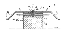
- FIG. 1 is a diagram showing a schematic configuration of an electrically heated catalyst 1 according to the first embodiment.
- the electrically heated catalyst 1 according to this embodiment is provided in the exhaust pipe 2 of the internal combustion engine mounted on the vehicle.
- the internal combustion engine may be a diesel engine or a gasoline engine. It can also be used in a vehicle that employs a hybrid system equipped with an electric motor.
- FIG. 1 is a cross-sectional view of the electrically heated catalyst 1 cut in the longitudinal direction along the central axis A of the exhaust pipe 2.
- the electrically heated catalyst 1 shown in FIG. Since the shape of the electrically heated catalyst 1 is symmetrical with respect to the central axis A, only the upper part is shown in FIG.
- the electrically heated catalyst 1 includes a cylindrical catalyst carrier 3 centering on a central axis A.
- a catalyst carrier 3, an inner tube 4, and a case 5 are provided in this order from the central axis A side.
- a mat 6 is provided between the catalyst carrier 3 and the inner tube 4 and between the inner tube 4 and the case 5.
- the catalyst carrier 3 is made of a material that generates electrical resistance and generates heat when energized.
- SiC is used as the material of the catalyst carrier 3.
- the catalyst carrier 3 has a plurality of passages extending in the direction in which the exhaust flows (that is, in the direction of the central axis A) and having a cross section perpendicular to the direction in which the exhaust flows in a honeycomb shape. Exhaust gas flows through this passage.
- the outer shape of the catalyst carrier 3 is, for example, a cylindrical shape centered on the central axis A of the exhaust pipe 2.
- the cross-sectional shape of the catalyst carrier 3 having a cross section orthogonal to the central axis A may be, for example, an ellipse.
- the central axis A is a central axis common to the exhaust pipe 2, the catalyst carrier 3, the inner pipe 4, and the case 5.
- the catalyst is supported on the catalyst carrier 3.
- the catalyst include an oxidation catalyst, a three-way catalyst, an NOx storage reduction catalyst, and a selective reduction NOx catalyst.
- Two electrodes 7 are connected to the catalyst carrier 3, and the catalyst carrier 3 is energized by applying a voltage between the electrodes 7.
- the catalyst carrier 3 generates heat due to the electrical resistance of the catalyst carrier 3.
- the catalyst carrier 3 corresponds to the heating element in the present invention. Further, a heating element may be provided upstream of the catalyst. If it does so, exhaust_gas
- an electrical insulating material is used, for example, a ceramic fiber mainly composed of alumina.
- the mat 6 is wound around the outer peripheral surface of the catalyst carrier 3 and the outer peripheral surface of the inner tube 4. Since the mat 6 covers the outer peripheral surface of the catalyst carrier 3 (a surface parallel to the central axis A), electricity is prevented from flowing to the inner tube 4 and the case 5 when the catalyst carrier 3 is energized. .
- the inner tube 4 is formed in a tubular shape around the central axis A.
- the inner tube 4 is longer in the central axis A direction than the mat 6. For this reason, the inner tube 4 protrudes from the mat 6 to the upstream side and the downstream side.
- the inner diameter of the inner tube 4 is substantially the same as the outer diameter of the mat 6 when the outer periphery of the catalyst carrier 3 is covered with the mat 6.
- An insulating layer 41 is formed on the surface of the inner tube 4.
- the insulating layer 41 is made of ceramic, for example. Since the insulating layer 41 is formed on the surface of the inner tube 4, even if a metal is used for the inner tube 4, electricity is suppressed from flowing through the inner tube 4.
- the material of the case 5 is a metal, and for example, a stainless steel material can be used.
- the case 5 includes an accommodating portion 51 that includes a curved surface parallel to the central axis A, and a tapered portion 52 that connects the accommodating portion 51 and the exhaust pipe 2 on the upstream side and the downstream side of the accommodating portion 51. 53.
- the catalyst carrier 3, the inner tube 4, and the mat 6 are accommodated inside the accommodating portion 51.
- the tapered portions 52 and 53 have a tapered shape in which the passage cross-sectional area decreases as the distance from the accommodating portion 51 increases. That is, the taper portion 52 upstream of the catalyst carrier 3 has a smaller sectional area toward the upstream side, and the taper portion 53 downstream of the catalyst carrier 3 has a smaller sectional area toward the downstream side.
- the inner diameter of the accommodating portion 51 is substantially the same as the outer diameter of the mat 6 when the outer periphery of the inner tube 4 is covered with the mat 6.
- Two electrodes 7 are connected to the catalyst carrier 3.
- holes 40 and 54 are provided in the inner tube 4 and the case 5, respectively.
- the mat 6 is not provided around the electrode 7 until the electrode 7 is connected to the catalyst carrier 3.
- An insulating material 8 that supports the electrode 7 is provided in the hole 54 formed in the case 5.
- the insulating material 8 is provided between the case 5 and the electrode 7 without a gap.
- an electrode chamber 9 that is a closed space around the electrode 7 is formed in the case 5.
- the inner tube 4 may be divided into an upstream side and a downstream side with respect to the electrode chamber 9 and may be installed separately.
- the mat 6 may also be divided into an upstream side and a downstream side with respect to the electrode chamber 9 and may be installed separately from each other. As a result, the electrode chamber 9 goes around the catalyst carrier 3 once.
- the thickness of the insulating layer 41 formed on the surface of the inner tube 4 is different between the inner peripheral surface side and the outer peripheral surface side of the inner tube 4. That is, the insulating layer 401 on the inner peripheral surface side of the inner tube 4 (hereinafter referred to as the inner insulating layer 401) is more than the insulating layer 402 on the outer peripheral surface side of the inner tube 4 (hereinafter referred to as the outer insulating layer 402). It is formed to be thin.
- the outer insulating layer 402 is compared by increasing the number of repetitions on the outer peripheral surface side rather than the inner peripheral surface side of the inner tube 4. Can be thickened.
- water condensed on the upstream side of the catalyst carrier 3 may flow on the inner wall of the exhaust pipe 2 or the case 5 and adhere to the mat 6.
- the water adheres to the mat 6 between the inner tube 4 and the accommodating portion 51.
- the presence of the inner tube 4 suppresses water from entering the inner side of the inner tube 4.
- the inner pipe 4 protrudes upstream and downstream from the mat 6, water is further suppressed from entering the inner side than the inner pipe 4. For this reason, it is suppressed that case 5 and the catalyst support
- the case 5 and the catalyst carrier 3 may be short-circuited by the PM.
- the inner tube 4 protrudes from the mat 6 and the temperature of the protruding portion is increased due to the heat of the exhaust, the PM adhering to the inner tube 4 can be oxidized and removed. Thereby, it is suppressed that case 5 and the catalyst support
- FIG. 2 is a diagram showing the relationship between the insulation resistance value of the insulating layer 41 and the temperature.
- the solid line indicates the case where the insulating layer 41 is relatively thick, and the alternate long and short dash line indicates the case where the insulating layer 41 is relatively thin.
- a broken line is a lower limit value of the insulation resistance value required for the insulating layer 41.
- the insulation resistance value of the insulating layer 41 decreases as the temperature increases. That is, the higher the temperature, the easier it is for electricity to flow. At the same temperature, the insulation resistance value increases as the insulating layer 41 is thicker. Therefore, the insulating layer 41 is preferably thickened to ensure the required insulation resistance value under high temperature conditions.
- the insulating layer 41 also has a heat insulating performance, the heat insulating performance increases as the insulating layer 41 becomes thicker. For this reason, if the insulating layer 41 is made too thick, heat from the catalyst carrier 3 becomes difficult to be transferred to the mat 6 outside the inner tube 4, so that the water staying in the mat 6 outside the inner tube 4 is retained. Evaporation takes time.
- the temperature on the inner peripheral surface side of the inner tube 4 is high because it receives heat from the catalyst carrier 3.
- the temperature on the outer peripheral surface side of the inner tube 4 is low because heat escapes from the case 5.
- the insulation resistance value is higher on the outer peripheral surface side where the temperature is lower than on the inner peripheral surface side.
- the overall insulation resistance value can be increased even if the overall thickness of the insulating layer 41 is the same. it can. Moreover, since the heat insulation performance can be suppressed by making the inner insulating layer 401 thinner by increasing the thickness of the outer insulating layer 402, water staying in the mat 6 outside the inner tube 4 can also be evaporated. .
- the inner insulating layer 401 thin, the temperature of the inner tube 4 is likely to rise. Further, by increasing the thickness of the outer insulating layer 402, it is possible to suppress heat from escaping from the inner tube 4 to the case 5. That is, since the temperature of the inner tube 4 can be maintained high, it is possible to promote the oxidation of particulate matter (PM) adhering to a portion where the inner tube 4 protrudes upstream or downstream of the mat 6. it can. That is, the short circuit by PM can be suppressed.
- PM particulate matter
- the inner insulating layer 401 and the outer insulating layer 402 are relatively thicker when the outer insulating layer 402 is relatively thicker than when the inner insulating layer 401 and the outer insulating layer 402 have the same insulating layer thickness. Even if the total thickness is the same, the insulation resistance value of the insulating layer 41 as a whole can be increased. Moreover, since it can suppress that the total value of the thickness as the insulating layer 41 whole increases, it can suppress that a heat
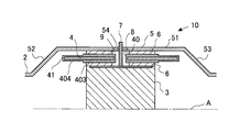
- FIG. 3 is a diagram showing a schematic configuration of the electrically heated catalyst 10 according to the second embodiment. Differences from the electrically heated catalyst 1 shown in Example 1 will be described. In addition, the same code
- FIG. 3 is a diagram showing a schematic configuration of the electrically heated catalyst 10 according to the second embodiment. Differences from the electrically heated catalyst 1 shown in Example 1 will be described. In addition, the same code
- the insulating layer 41 formed on the surface of the inner tube 4 and the insulating layer 41 in the portion where the mat 6 is provided (the portion in contact with the mat 6) is referred to as “the insulating layer 403 in the mat”.
- the insulating layer 41 formed on the surface of the inner pipe 4 and protruding from the mat 6 to the upstream side or the downstream side of the exhaust is referred to as an “outer mat insulating layer 404”.
- the in-mat insulating layer 403 may be the insulating layer 41 downstream from the upstream end of the mat 6 and upstream from the downstream end of the mat 6.
- the mat outer insulating layer 404 may be the insulating layer 41 at the upstream side of the upstream end of the mat 6 or the insulating layer 41 at a downstream side of the downstream end of the mat 6.
- the insulating layer 404 outside the mat is formed thinner than the insulating layer 403 in the mat.
- the in-mat insulating layer 403 is compared with the in-mat insulating layer 403 by increasing the number of repetitions in the in-mat insulating layer 403 compared to the outside-mat insulating layer 404. Can be thickened.
- the insulating layer 403 in the mat is required to have high insulating performance. Further, due to the heat insulating effect of the mat 6, the temperature of the in-mat insulating layer 403 is kept relatively high. Accordingly, the in-mat insulating layer 403 is preferably thick. That is, even if the temperature is high, if the in-mat insulating layer 403 is made thick, a required insulation resistance value can be secured.
- the thickness of the insulating layer 41 may be the same as that of the in-mat insulating layer 403 even if the portion protrudes from the mat 6 as long as it is in the vicinity of the mat 6. In other words, the insulating layer 41 may be made relatively thick at the portion where the mat 6 is provided and the portion in the vicinity thereof.
- FIG. 4 is a diagram showing a schematic configuration of the electrically heated catalyst 10 in a case where the insulating layer 41 is relatively thick at a portion where the mat 6 is provided and a portion in the vicinity thereof.
- the range in which the insulating layer 41 is relatively thick may be a range in which water attached to the upstream end or the downstream end of the mat 6 reaches.
- the insulating layer 41 in a range where the insulation resistance value may decrease due to a high temperature may be relatively thick.
- the second embodiment by increasing the thickness of the in-mat insulating layer 403 and decreasing the thickness of the outer mat insulating layer 404, the area where the insulating layer is thickened while ensuring the required insulation resistance value is obtained. Since it can suppress, cost increase can be suppressed.
- FIG. 5 is a diagram showing a schematic configuration of the electrically heated catalyst 11 according to the third embodiment. Differences from the electrically heated catalysts 1 and 10 shown in Examples 1 and 2 will be described. In addition, the same code
- the insulating layer 41 in the portion where the mat 6 is provided and the insulating layer 41 on the inner peripheral surface side of the inner tube 4 is referred to as “in-mat-inside insulating layer 405”.
- the insulating layer 41 in the portion where the mat 6 is provided, and the insulating layer 41 on the outer peripheral surface side of the inner tube 4 is referred to as “mat inner-outer insulating layer 406”.
- the insulating layer 41 formed on the surface of the inner pipe 4 and protruding from the mat 6 to the upstream side or the downstream side of the exhaust is referred to as an “outer mat insulating layer 404”.
- the inner-outer insulating layer 406 in the mat is made thicker than the insulating layer 41 in other portions.
- the inner-outer insulating layer 406 is thicker than the inner-inside insulating layer 405 and the outer insulating layer 404 outside the mat.
- the in-mat-outside insulating layer 406 is compared with the inside-outside insulating layer 406 by repeating this repetition more than the others. Can be thickened.
- the insulating resistance value of the insulating layer 41 as a whole can be increased by making the inner mat-outer insulating layer 406 thicker than the inner mat-inner insulating layer 405 at the portion in contact with the mat 6. Can do. Moreover, since it can suppress that the thickness as the whole of the insulating layer 41 increases, it can suppress that a heat
- the area where the insulating layer becomes thick can be suppressed while ensuring the required insulation resistance value.
- FIG. 6 is a diagram showing a schematic configuration of the electrically heated catalyst 11 when the insulating layer 41 on the outer peripheral surface side of the inner tube 4 is relatively thickened at the portion where the mat 6 is provided and in the vicinity thereof. is there.
- the range in which the insulating layer 41 is relatively thick may be a range in which water attached to the upstream end or the downstream end of the mat 6 reaches. That is, it is good also as a range for which high insulation performance is requested
- FIG. 7 is a diagram showing a schematic configuration of the electrically heated catalyst 12 according to the fourth embodiment. Differences from the electrically heated catalyst 1 shown in Example 1 will be described. In addition, the same code
- FIG. 7 is a diagram showing a schematic configuration of the electrically heated catalyst 12 according to the fourth embodiment. Differences from the electrically heated catalyst 1 shown in Example 1 will be described. In addition, the same code
- FIG. 7 is a cross-sectional view of the electrically heated catalyst 12 cut along a plane orthogonal to the central axis.
- hatching other than the inner tube 4, the insulating layer 41, and the electrode 7 is omitted.
- the electrode 7 includes an anode 71 and a cathode 72.
- the anode 71 and the cathode 72 are provided along the outer peripheral surface of the catalyst carrier 3. Then, since the catalyst carrier 3 is present between the anode 71 and the cathode 72, electricity flows through the catalyst carrier 3.
- the insulating layer 41 is thickened at a location where the temperature rises, the required insulation resistance value can be secured. That is, the electrode 7 does not exist in the vicinity of the insulating layer 408 in the vicinity of the portion where the distance to the other electrode is the shortest in each of the anode 71 and the cathode 72 (see the portion surrounded by the one-dot chain line in FIG. 7). It is thicker than the insulating layer 409. Thereby, the fall of insulation performance can be suppressed. Note that the range in which the insulating layer 41 is relatively thick can be obtained by experiments or the like as the range in which the insulation resistance value may be reduced by heat.
- the insulating layer 41 that is less than a predetermined distance from the portion where the distance to the other electrode is the shortest in each of the anode 71 and the cathode 72 may be relatively thick. This predetermined distance can be obtained by experiments or the like as a range in which the insulation resistance value may decrease due to heat.
- FIG. 8 is another diagram showing a schematic configuration of the electrically heated catalyst 13 according to the fourth embodiment.
- FIG. 8 is a cross-sectional view of the electrically heated catalyst 12 taken along a plane orthogonal to the central axis. In FIG. 8, hatching other than the inner tube 4, the insulating layer 41, and the electrode 7 is omitted.
- the insulating layer 41 is thickened in the vicinity of the anode 71 and the cathode 72. That is, the insulating layer 410 in the vicinity of the electrode 7 is made thicker than the insulating layer 411 in which the electrode 7 does not exist in the vicinity. Thereby, even if the temperature of the whole electrode 7 rises, the required insulation resistance value can be ensured. Note that the insulating layer 41 less than a predetermined distance from the electrode 7 may be relatively thick.
Landscapes
- Chemical & Material Sciences (AREA)
- Engineering & Computer Science (AREA)
- Chemical Kinetics & Catalysis (AREA)
- Health & Medical Sciences (AREA)
- Toxicology (AREA)
- Combustion & Propulsion (AREA)
- Mechanical Engineering (AREA)
- General Engineering & Computer Science (AREA)
- Exhaust Gas After Treatment (AREA)
- Catalysts (AREA)
Abstract
Description
通電により発熱する発熱体と、
前記発熱体を収容するケースと、
前記発熱体と前記ケースとの間に設けられる内管と、
前記発熱体と前記内管との間及び前記内管と前記ケースとの間に設けられる電気を絶縁するマットと、
前記発熱体に接続され該発熱体に電力を供給する電極と、
を備え、
前記内管の表面には、電気を絶縁する絶縁層が形成されており、
前記絶縁層は、内管の外周面側よりも内周面側のほうが薄い。
通電により発熱する発熱体と、
前記発熱体を収容するケースと、
前記発熱体と前記ケースとの間に設けられる内管と、
前記発熱体と前記内管との間及び前記内管と前記ケースとの間に設けられる電気を絶縁するマットと、
前記発熱体に接続され該発熱体に電力を供給する電極と、
を備え、
前記内管は、前記マットよりも排気の流れ方向の上流側及び下流側へ突出しており、
前記内管の表面には、電気を絶縁する絶縁層が形成されており、
前記絶縁層は、前記マットよりも排気の流れ方向の上流側または下流側へ突出している部位のほうが、前記マットが設けられている部位よりも薄い。
通電により発熱する発熱体と、
前記発熱体を収容するケースと、
前記発熱体と前記ケースとの間に設けられる内管と、
前記発熱体と前記内管との間及び前記内管と前記ケースとの間に設けられる電気を絶縁するマットと、
前記発熱体に接続され該発熱体に電力を供給する電極と、
を備え、
前記内管の表面には、電気を絶縁する絶縁層が形成されており、
前記電極の一部は、前記発熱体の周方向に沿って該発熱体の外周面に形成されており、
前記絶縁層は、少なくとも夫々の電極において他の電極との距離が最短となる部位の近傍の部位のほうが、近傍に電極が存在しない部位よりも厚い。
2 排気管
3 触媒担体
4 内管
5 ケース
6 マット
7 電極
8 絶縁材
9 電極室
41 絶縁層
401 内側絶縁層
402 外側絶縁層
Claims (3)
- 通電により発熱する発熱体と、
前記発熱体を収容するケースと、
前記発熱体と前記ケースとの間に設けられる内管と、
前記発熱体と前記内管との間及び前記内管と前記ケースとの間に設けられる電気を絶縁するマットと、
前記発熱体に接続され該発熱体に電力を供給する電極と、
を備え、
前記内管の表面には、電気を絶縁する絶縁層が形成されており、
前記絶縁層は、内管の外周面側よりも内周面側のほうが薄い電気加熱式触媒。 - 通電により発熱する発熱体と、
前記発熱体を収容するケースと、
前記発熱体と前記ケースとの間に設けられる内管と、
前記発熱体と前記内管との間及び前記内管と前記ケースとの間に設けられる電気を絶縁するマットと、
前記発熱体に接続され該発熱体に電力を供給する電極と、
を備え、
前記内管は、前記マットよりも排気の流れ方向の上流側及び下流側へ突出しており、
前記内管の表面には、電気を絶縁する絶縁層が形成されており、
前記絶縁層は、前記マットよりも排気の流れ方向の上流側または下流側へ突出している部位のほうが、前記マットが設けられている部位よりも薄い電気加熱式触媒。 - 通電により発熱する発熱体と、
前記発熱体を収容するケースと、
前記発熱体と前記ケースとの間に設けられる内管と、
前記発熱体と前記内管との間及び前記内管と前記ケースとの間に設けられる電気を絶縁するマットと、
前記発熱体に接続され該発熱体に電力を供給する電極と、
を備え、
前記内管の表面には、電気を絶縁する絶縁層が形成されており、
前記電極の一部は、前記発熱体の周方向に沿って該発熱体の外周面に形成されており、
前記絶縁層は、少なくとも夫々の電極において他の電極との距離が最短となる部位の近傍の部位のほうが、近傍に電極が存在しない部位よりも厚い電気加熱式触媒。
Priority Applications (5)
| Application Number | Priority Date | Filing Date | Title |
|---|---|---|---|
| JP2012556681A JP5626371B2 (ja) | 2011-02-08 | 2011-02-08 | 電気加熱式触媒 |
| US13/981,004 US9046024B2 (en) | 2011-02-08 | 2011-02-08 | Electric heating catalyst |
| EP11858163.6A EP2674209B1 (en) | 2011-02-08 | 2011-02-08 | Electric heating catalyst |
| PCT/JP2011/052627 WO2012107997A1 (ja) | 2011-02-08 | 2011-02-08 | 電気加熱式触媒 |
| CN201180066925.0A CN103338844B (zh) | 2011-02-08 | 2011-02-08 | 电加热式催化剂 |
Applications Claiming Priority (1)
| Application Number | Priority Date | Filing Date | Title |
|---|---|---|---|
| PCT/JP2011/052627 WO2012107997A1 (ja) | 2011-02-08 | 2011-02-08 | 電気加熱式触媒 |
Publications (1)
| Publication Number | Publication Date |
|---|---|
| WO2012107997A1 true WO2012107997A1 (ja) | 2012-08-16 |
Family
ID=46638240
Family Applications (1)
| Application Number | Title | Priority Date | Filing Date |
|---|---|---|---|
| PCT/JP2011/052627 WO2012107997A1 (ja) | 2011-02-08 | 2011-02-08 | 電気加熱式触媒 |
Country Status (5)
| Country | Link |
|---|---|
| US (1) | US9046024B2 (ja) |
| EP (1) | EP2674209B1 (ja) |
| JP (1) | JP5626371B2 (ja) |
| CN (1) | CN103338844B (ja) |
| WO (1) | WO2012107997A1 (ja) |
Cited By (1)
| Publication number | Priority date | Publication date | Assignee | Title |
|---|---|---|---|---|
| CN105545430A (zh) * | 2014-10-28 | 2016-05-04 | 揖斐电株式会社 | 电加热式催化转化器 |
Families Citing this family (4)
| Publication number | Priority date | Publication date | Assignee | Title |
|---|---|---|---|---|
| JP6408865B2 (ja) * | 2014-10-28 | 2018-10-17 | イビデン株式会社 | 電気加熱式触媒コンバータ |
| EP3423684B1 (en) * | 2016-03-02 | 2020-05-06 | Watlow Electric Manufacturing Company | System for axial zoning of heating power |
| JP6626377B2 (ja) * | 2016-03-14 | 2019-12-25 | 日本碍子株式会社 | ハニカム型加熱装置並びにその使用方法及び製造方法 |
| DE102022129142A1 (de) * | 2022-11-04 | 2024-05-08 | Friedrich Boysen Gmbh & Co. Kg | Elektrisch beheizbare Einheit |
Citations (4)
| Publication number | Priority date | Publication date | Assignee | Title |
|---|---|---|---|---|
| JPH05146686A (ja) * | 1991-04-05 | 1993-06-15 | W R Grace & Co | 電気的に加熱しうる触媒コンバーター・コアに対するコア員 |
| JPH05277379A (ja) * | 1992-04-01 | 1993-10-26 | Nissan Motor Co Ltd | 排気浄化用触媒コンバータ装置 |
| JPH0647625U (ja) * | 1992-12-07 | 1994-06-28 | カルソニック株式会社 | 電熱式触媒コンバータ |
| JPH08210127A (ja) * | 1995-02-02 | 1996-08-20 | Nissan Motor Co Ltd | 内燃機関の触媒浄化装置 |
Family Cites Families (8)
| Publication number | Priority date | Publication date | Assignee | Title |
|---|---|---|---|---|
| US5070694A (en) * | 1990-10-31 | 1991-12-10 | W. R. Grace & Co. -Conn. | Structure for electrically heatable catalytic core |
| US5140812A (en) * | 1991-11-05 | 1992-08-25 | W. R. Grace & Co.-Conn. | Core for an electrically heatable catalytic converter |
| JPH05269387A (ja) * | 1992-03-26 | 1993-10-19 | Nissan Motor Co Ltd | 排気浄化用触媒コンバータ装置 |
| JPH0576530U (ja) * | 1992-03-30 | 1993-10-19 | カルソニック株式会社 | 排気浄化用電気発熱式金属担体触媒コンバータ |
| DE4430645A1 (de) * | 1994-08-29 | 1996-03-07 | Emitec Emissionstechnologie | Katalytischer Reaktor |
| DE10046610C1 (de) * | 2000-09-20 | 2002-04-25 | Emitec Emissionstechnologie | Fest-Los-Lagerung eines Katalysator-Trägerkörpers |
| GB0507326D0 (en) * | 2005-04-12 | 2005-05-18 | Delphi Tech Inc | Catalytic converter apparatus and method |
| WO2012093481A1 (ja) * | 2011-01-06 | 2012-07-12 | イビデン株式会社 | 排ガス処理装置 |
-
2011
- 2011-02-08 WO PCT/JP2011/052627 patent/WO2012107997A1/ja active Application Filing
- 2011-02-08 EP EP11858163.6A patent/EP2674209B1/en not_active Not-in-force
- 2011-02-08 US US13/981,004 patent/US9046024B2/en not_active Expired - Fee Related
- 2011-02-08 JP JP2012556681A patent/JP5626371B2/ja not_active Expired - Fee Related
- 2011-02-08 CN CN201180066925.0A patent/CN103338844B/zh not_active Expired - Fee Related
Patent Citations (4)
| Publication number | Priority date | Publication date | Assignee | Title |
|---|---|---|---|---|
| JPH05146686A (ja) * | 1991-04-05 | 1993-06-15 | W R Grace & Co | 電気的に加熱しうる触媒コンバーター・コアに対するコア員 |
| JPH05277379A (ja) * | 1992-04-01 | 1993-10-26 | Nissan Motor Co Ltd | 排気浄化用触媒コンバータ装置 |
| JPH0647625U (ja) * | 1992-12-07 | 1994-06-28 | カルソニック株式会社 | 電熱式触媒コンバータ |
| JPH08210127A (ja) * | 1995-02-02 | 1996-08-20 | Nissan Motor Co Ltd | 内燃機関の触媒浄化装置 |
Non-Patent Citations (1)
| Title |
|---|
| See also references of EP2674209A4 * |
Cited By (1)
| Publication number | Priority date | Publication date | Assignee | Title |
|---|---|---|---|---|
| CN105545430A (zh) * | 2014-10-28 | 2016-05-04 | 揖斐电株式会社 | 电加热式催化转化器 |
Also Published As
| Publication number | Publication date |
|---|---|
| JPWO2012107997A1 (ja) | 2014-07-03 |
| EP2674209B1 (en) | 2015-10-07 |
| US9046024B2 (en) | 2015-06-02 |
| EP2674209A1 (en) | 2013-12-18 |
| JP5626371B2 (ja) | 2014-11-19 |
| CN103338844A (zh) | 2013-10-02 |
| CN103338844B (zh) | 2015-05-20 |
| EP2674209A4 (en) | 2014-07-16 |
| US20130305698A1 (en) | 2013-11-21 |
Similar Documents
| Publication | Publication Date | Title |
|---|---|---|
| EP2685061B1 (en) | Exhaust gas purification apparatus of an internal combustion engine | |
| JP5626371B2 (ja) | 電気加熱式触媒 | |
| JP5761362B2 (ja) | 電気加熱式触媒 | |
| JP2015132256A (ja) | 内燃機関の触媒装置 | |
| JP2013185573A (ja) | 電気加熱式触媒 | |
| JP5263456B2 (ja) | 電気加熱式触媒 | |
| JP5617938B2 (ja) | 電気加熱式触媒 | |
| JP5673683B2 (ja) | 電気加熱式触媒 | |
| JP5626375B2 (ja) | 電気加熱式触媒 | |
| CN103442788A (zh) | 电加热催化剂 | |
| US8647584B2 (en) | Electric heating catalyst | |
| JP5472468B2 (ja) | 電気加熱式触媒 | |
| US8894942B2 (en) | Electrically heated catalyst | |
| JP5397550B2 (ja) | 電気加熱式触媒 | |
| JP5601240B2 (ja) | 触媒コンバータ装置 | |
| JP2023153607A (ja) | 触媒装置 | |
| JP2011220323A (ja) | 電気加熱式触媒 |
Legal Events
| Date | Code | Title | Description |
|---|---|---|---|
| 121 | Ep: the epo has been informed by wipo that ep was designated in this application |
Ref document number: 11858163 Country of ref document: EP Kind code of ref document: A1 |
|
| ENP | Entry into the national phase |
Ref document number: 2012556681 Country of ref document: JP Kind code of ref document: A |
|
| WWE | Wipo information: entry into national phase |
Ref document number: 13981004 Country of ref document: US |
|
| WWE | Wipo information: entry into national phase |
Ref document number: 2011858163 Country of ref document: EP |
|
| NENP | Non-entry into the national phase |
Ref country code: DE |