EP3418876A1 - Information processing apparatus and information processing method - Google Patents
Information processing apparatus and information processing method Download PDFInfo
- Publication number
- EP3418876A1 EP3418876A1 EP18183557.0A EP18183557A EP3418876A1 EP 3418876 A1 EP3418876 A1 EP 3418876A1 EP 18183557 A EP18183557 A EP 18183557A EP 3418876 A1 EP3418876 A1 EP 3418876A1
- Authority
- EP
- European Patent Office
- Prior art keywords
- area
- touch
- display
- information processing
- processing apparatus
- Prior art date
- Legal status (The legal status is an assumption and is not a legal conclusion. Google has not performed a legal analysis and makes no representation as to the accuracy of the status listed.)
- Ceased
Links
Images


Classifications
-
- G—PHYSICS
- G06—COMPUTING OR CALCULATING; COUNTING
- G06F—ELECTRIC DIGITAL DATA PROCESSING
- G06F3/00—Input arrangements for transferring data to be processed into a form capable of being handled by the computer; Output arrangements for transferring data from processing unit to output unit, e.g. interface arrangements
- G06F3/01—Input arrangements or combined input and output arrangements for interaction between user and computer
- G06F3/03—Arrangements for converting the position or the displacement of a member into a coded form
- G06F3/041—Digitisers, e.g. for touch screens or touch pads, characterised by the transducing means
- G06F3/0416—Control or interface arrangements specially adapted for digitisers
-
- G—PHYSICS
- G06—COMPUTING OR CALCULATING; COUNTING
- G06F—ELECTRIC DIGITAL DATA PROCESSING
- G06F1/00—Details not covered by groups G06F3/00 - G06F13/00 and G06F21/00
- G06F1/16—Constructional details or arrangements
- G06F1/1601—Constructional details related to the housing of computer displays, e.g. of CRT monitors, of flat displays
-
- G—PHYSICS
- G06—COMPUTING OR CALCULATING; COUNTING
- G06F—ELECTRIC DIGITAL DATA PROCESSING
- G06F3/00—Input arrangements for transferring data to be processed into a form capable of being handled by the computer; Output arrangements for transferring data from processing unit to output unit, e.g. interface arrangements
- G06F3/01—Input arrangements or combined input and output arrangements for interaction between user and computer
- G06F3/03—Arrangements for converting the position or the displacement of a member into a coded form
- G06F3/041—Digitisers, e.g. for touch screens or touch pads, characterised by the transducing means
- G06F3/042—Digitisers, e.g. for touch screens or touch pads, characterised by the transducing means by opto-electronic means
- G06F3/0428—Digitisers, e.g. for touch screens or touch pads, characterised by the transducing means by opto-electronic means by sensing at the edges of the touch surface the interruption of optical paths, e.g. an illumination plane, parallel to the touch surface which may be virtual
-
- G—PHYSICS
- G06—COMPUTING OR CALCULATING; COUNTING
- G06F—ELECTRIC DIGITAL DATA PROCESSING
- G06F3/00—Input arrangements for transferring data to be processed into a form capable of being handled by the computer; Output arrangements for transferring data from processing unit to output unit, e.g. interface arrangements
- G06F3/01—Input arrangements or combined input and output arrangements for interaction between user and computer
- G06F3/048—Interaction techniques based on graphical user interfaces [GUI]
- G06F3/0487—Interaction techniques based on graphical user interfaces [GUI] using specific features provided by the input device, e.g. functions controlled by the rotation of a mouse with dual sensing arrangements, or of the nature of the input device, e.g. tap gestures based on pressure sensed by a digitiser
- G06F3/0488—Interaction techniques based on graphical user interfaces [GUI] using specific features provided by the input device, e.g. functions controlled by the rotation of a mouse with dual sensing arrangements, or of the nature of the input device, e.g. tap gestures based on pressure sensed by a digitiser using a touch-screen or digitiser, e.g. input of commands through traced gestures
-
- G—PHYSICS
- G06—COMPUTING OR CALCULATING; COUNTING
- G06F—ELECTRIC DIGITAL DATA PROCESSING
- G06F2203/00—Indexing scheme relating to G06F3/00 - G06F3/048
- G06F2203/033—Indexing scheme relating to G06F3/033
- G06F2203/0339—Touch strips, e.g. orthogonal touch strips to control cursor movement or scrolling; single touch strip to adjust parameter or to implement a row of soft keys
Definitions
- the present disclosure relates to an information processing apparatus and to an information processing method.
- an information processing apparatus such as a PC (Personal Computer) tends to install a touch panel.
- a display area and a touch operation valid area correspond to each other in this touch panel.
- a touch operation by the user may be difficult because a frame surrounding the display area of the display apparatus becomes obstacle and a contact range of the finger is larger than the size of the icon, for example.
- Patent Document 1 discloses a touch panel that facilitates touch inputs to the peripheral portion of a display screen by setting a touch input valid area to be larger than the display screen.
- Patent Documents 2 and 3 disclose a portable device that enables touch operations to be made in not only a display but also a bezel and border area surrounding it.
- the frame surrounding the display screen is not obstacle any more, as long as the icon displayed in the corner of the display screen has a size significantly smaller than the contact area of the user's finger, for example, it is still difficult for the user to correctly touch the position of the icon.
- Embodiments of the present disclosure relate to an information processing apparatus that enables touch operations to be made, and to an information processing method in such an information processing apparatus.
- an information processing apparatus including a display panel, a frame, a touch sensor, and a controller.
- the display panel includes a display surface of a predetermined display area.
- the frame includes a frame surface that surrounds the display panel and determines the display area.
- the touch sensor is configured to detect touches to the display surface and the frame surface.
- the controller is configured to execute predetermined processing when a touch to a first area on the display surface is detected, and to execute the predetermined processing when a touch to a second area on the frame surface is detected, the second area being adjacent to the first area.
- the information processing apparatus can improve touch operability by extending an operation range with respect to a touch operation target displayed on the display surface beyond the display area.
- the predetermined processing means an operation of closing a window, for example.
- the information processing apparatus may further include an output unit configured to output, when the touch to the second area is detected, information indicating detection of the touch.
- the frame is incapable of providing, by itself, the user with a feedback about a touch unlike an icon and the like displayed on the display panel, for example.
- the information processing apparatus can provide a feedback about a touch to the frame.
- the controller may control, when the touch to the second area is detected, the output unit to display on the display panel a predetermined animation indicating detection of the touch.
- the information processing apparatus can visually provide a feedback about a touch to the frame.
- the controller may control the output unit so that the animation becomes gradually larger with a position of the touch in the second area being a center.
- the information processing apparatus can easily inform the user which position the user has actually touched on the frame.
- the output unit may include a speaker.
- the controller may control, when the touch to the second area is detected, the output unit to output through the speaker a predetermined sound indicating detection of the touch.
- the information processing apparatus can acoustically provide a feedback about a touch to the frame.
- the information processing apparatus may further include a glass plate that is provided to integrally cover the frame surface and the display surface.
- the information processing apparatus can realize a flush surface screen by use of the glass plate, to thereby prevent the user from recognizing whether the user touches the first area or the second area.
- the glass plate may include one of printed information and carved information indicating content of the predetermined processing at a position corresponding to the second area in one of a front surface and a back surface of the glass plate.
- the information processing apparatus can cause the user to easily understand that the predetermined processing to be executed by the touch to the first area can be also executed by the touch to the second area.
- an information processing method in an information processing apparatus including a display panel, a frame, and a touch sensor, the display panel including a display surface of a predetermined display area, the frame including a frame surface that surrounds the display panel and determines the display area.
- touches to the display surface and the frame surface are detected by the touch sensor.
- predetermined processing is executed.
- the predetermined processing is executed, the second area being adjacent to the first area.
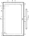
- FIG. 1 is a front view showing an outer appearance of a PC according to an embodiment of the present disclosure. Further, FIG. 2 is a partial sectional view of the PC shown in FIG. 1 , which is taken from the line A-A.
- the PC 100 includes a casing 1 and a stand 2.
- the casing 1 is provided with an LCD (Liquid Crystal Display) 16 and a frame 4 that supports the LCD 16 around the LCD 16.
- the PC 100 is a display-integrated type PC including the casing 1 that houses an HDD (Hard Disk Drive) as well as a motherboard.
- HDD Hard Disk Drive
- a glass plate 3 is bonded on the LCD 16, a glass plate 3 is bonded. As shown in FIG. 2 , the glass plate 3 has a display area larger than a valid display area of the LCD 16. In the periphery of the back surface of the glass plate 3, an opaque print area 3a is formed to have a frame shape. This print area 3a determines the valid display area of the LCD 16. Although the color of the print area 3a is, for example, black, various color variations are possible. Further, it is not limited to a single color, and various patterns may be applied by printing.
- each of the cameras 21 is one that includes an infrared emitter and a receiver, which are integrally formed.
- a light retroreflective tape 31 that reflects infrared rays emitted from the infrared emitters is bonded.
- the light retroreflective tape 31 contains, within its film, glass beads or the like, and includes constant perpendicular surfaces with respect to the light in any direction.
- the infrared rays emitted from the infrared emitters are reflected by the light retroreflective tape 31 toward the cameras 21 and received by the receivers.
- the infrared rays emitted from the infrared emitters are not received by the receivers, and detected as the shadow of the finger. Based on the position of this shadow, the touch position is calculated using the triangulation principle. Further, by this processing, the optical touch sensor unit can also perform a multi-touch detection. The optical touch sensor unit will be described later in detail.
- the optical touch sensor unit can detect touches by the user over the glass plate 3. Therefore, a touch operation valid area exists in not only the LCD 16 but also the print area 3a surrounding it.
- a function for enabling the touch operations to be made in the print area 3a is referred to as edge access function, and the print area 3a is also referred to as edge access area.
- a group of status displays 5 that display statuses including a TV mode, an HDMI (High-Definition Multimedia Interface) mode, a video mode, a web mode, a wireless mode, turning ON/OFF, and the like.
- an edge access setting button 6 and a 3D mode status display 7 are printed in the lower right of the print area 3a.
- a desktop/window switch button 10 is printed in the lower left of the print area 3a.
- trademark logos 8, 9 are printed. Among them, the edge access setting button 6, the trademark logos 8, 9, and the desktop/window switch button 10 become edge access function targets. That is, by touching those buttons and logos, the user can cause the PC 100 to execute various functions. The edge access function will be described later in detail.
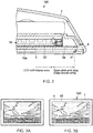
- FIGS. 3 are views showing an effect of this bonding technique.
- FIG. 3A shows the front of a traditional PC filled with the air instead of the bonding resin
- FIG. 3B shows the front of the PC 100 according to this embodiment.
- the gap between the LCD 16 and the glass plate 3 is filled with the bonding resin instead of the air layer, and hence the external light can be prevented from diffusely reflecting due to the air layer, and it looks like the image was embossed onto the glass plate 3.
- a user interface displayed on the LCD 16 will be provided in the front surface of the glass plate 3 together with the edge access function.
- the glass plate 3 covers a range lager than the valid display area of the LCD 16.
- a so-called flush surface design is realized.
- the above-mentioned light retroreflective tape is provided in the inner surfaces of the frame, and hence a step is necessarily formed between the glass plate and the frame.
- the position of the step substantially corresponds to the ends of the valid display area of the LCD and the glass plate. Therefore, the step makes a shadow on the screen of the LCD. This becomes a very annoying element during viewing a film and a TV.
- the light retroreflective tape has constant perpendicular surfaces with respect to the light in any direction, and hence, for example, waved mirror images of a fluorescent light and the like can be seen in the tape and fall in the LCD, which becomes an annoying element as in the above description.
- the frame surrounding the glass plate is typically processed to be matte black.
- the print area 3a is formed in the back surface of the glass plate 3 and spaced away from the area, through which the infrared rays pass, in a thickness direction by the thickness of the glass plate 3 (approximately 2 to 2.5 mm). Therefore, the print area 3a is less likely to be affected by the reflection.
- the PC 100 having a variety of colors can be realized.
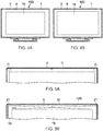
- FIGS. 4 are views showing a state in which the size of the valid display area of the LCD 16 is changed due to the difference of the size of the print area 3a.
- a model of the LCD 16 which has a different inch size, can be manufactured without changing the size of the casing 1. Since the size of the casing 1 is not changed even when the inch size of the LCD 16 is changed, many parts are shared. Further, regarding software that realizes the edge access function, by preparing coordinate tables of different function definitions depending on the inch sizes and switching them, it can be also shared.
- FIGS. 5 are views showing the upper portion of the PC 100 in comparison with the traditional PC including the optical touch panel.
- FIG. 5A shows the upper portion of the traditional PC
- FIG. 5B shows the upper portion of the PC 100 of this embodiment.
- infrared rays emitted from two cameras C pass through the inside of a front panel of a frame F, and hence it may be impossible to provide a structure that blocks out the infrared rays in an area D in the inside of the front panel. Therefore, a cavity is formed in the inside of the front panel, and the front panel can be deflected when the user holds the front panel with the hand, for example, which becomes a problem in terms of rigidity.
- FIG. 5A shows the upper portion of the traditional PC
- FIG. 5B shows the upper portion of the PC 100 of this embodiment.
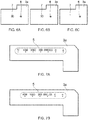
- FIGS. 6 and 7 are views showing status displays by this printing.
- the edge access setting button 6 and the 3D mode status display 7 are formed by outlining and printing characters on the black background of the print area 3a.
- LEDs Light-Emitting Diodes
- those characters are formed by medium printing processing, and hence it becomes also possible to hide the characters from view by turning ON/OFF the LEDs.
- the 3D mode status display 7 can be expressed in three statuses of a disabled state, stand-by state, and actuation state.
- existence or absence of various functions of the PC 100 can be expressed only by printing processing with respect to the print area 3a.
- existence of that function is expressed by printing in FIG. 7A .
- FIG. 7B by using a printing plate without a portion corresponding to that function, absence of that function is expressed without changing other hardware components.
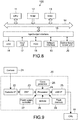
- FIG. 8 is a block diagram showing a hardware configuration of the PC 100.
- the PC 100 includes a CPU (Central Processing Unit) 11, a ROM (Read Only Memory) 12, a RAM (Random Access Memory) 13, an input/output interface 15, and a bus 14 that connects them to each other.
- a CPU Central Processing Unit
- ROM Read Only Memory
- RAM Random Access Memory
- the CPU 11 appropriately access the RAM 13 or the like depending on needs, and performs various types of arithmetic processing to generally control the respective blocks of the PC 100.
- the ROM 12 is a non-volatile memory in which an OS and various types of firmware such as programs and various parameters are fixedly stored, which are executed by the CPU 11.
- the RAM 13 is used as a work area or the like of the CPU 11 to temporarily hold the OS, executed various applications, and various types of processed data.
- the LCD 16 To the input/output interface 15, the LCD 16, the input unit 17, an HDD 18, a network interface 19, an optical touch sensor unit 20, and the like are connected. Further, although not shown in the drawing, to the input/output interface 15, a speaker that outputs sound is also connected.
- the LCD 16 displays screens of the various applications, video of content, and the like.
- another device such as a plasma display or an OELD (Organic Electro-Luminescence Display) may be used.
- the input unit 17 includes, for example, pointing devices such as a mouse, a keyboard, switches, and other operating apparatuses.
- the HDD 18 is, for example, a non-volatile memory such as an HDD, a flash memory, or another solid-state memory.
- the OS various applications, and various types of data are stored.
- applications, data, and the like necessary for executing the edge access function are also stored.
- the network interface 19 is a NIC (Network Interface Card) or the like for connection to the Internet or a network such as a LAN (Local Area Network).
- the network interface 19 may communicate in a wired or wireless manner.
- FIG. 9 is a block diagram showing a configuration of the optical touch sensor unit 20.
- the optical touch sensor unit 20 includes, in addition to the above-mentioned cameras 21, a camera interface (I/F) 22, a DSP (Digital Signal Processor) 23, a processor 24, a USB (Universal Serial Bus) interface (I/F) 25, a clock generator 26, a power supply controller 27, an SDRAM (Synchronous DRAM) 28, and a flash memory 29.
- the processor 24 calculates, appropriately in cooperation with the clock generator 26, the power supply controller 27, the SDRAM 28, and the flash memory 29, a touch position using the triangulation, and transmits, via the USB interface 25, the calculation result to the CPU 11.
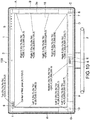
- FIG. 10 is a view showing a valid area definition of the edge access function.
- different functions are assigned to areas A to I shown by the alternate long and short dash lines.
- the areas are defined by coordinate systems with the upper left end of the valid display area of the LCD 16 being an origin (0,0).
- the areas are defined to have an extra size of about 3 mm up to a virtual position outside the edges of the frame. With this, it is possible to absorb a variation in components and dimension during manufacturing.
- certain operation target areas include no intentional indication by printing or the like, and hence those areas are set to have a relatively large range.
- reaction portions are set to be larger in upper and lower directions as compared to left- and right-hand directions. That is because it is assumed that the edge access function is basically operated by the finger of the user, the operation by the finger causes a larger error in the upper and lower directions as compared to the left- and right-hand directions, and it is desirable that the characters of the logo be not hidden by the finger during the operation by the user.
- the reaction area surrounding the logo is set to have a range of from the end of the logo to 5 mm in the left- and right-hand directions and 8 mm in the upper and lower directions.
- the PC 100 a plurality of applications (or utility software) are executed, and hence functions assigned to the areas A to I may be different depending on the plurality of applications. That is, the PC 100 includes a corresponding database of functions (key codes) assigned to the areas and applications in the HDD 18 or the like, and can switch the key codes assigned to the areas A to I depending on a currently highlighted application.
- functions key codes assigned to the areas and applications in the HDD 18 or the like
- the GUIs of the applications there are a GUI that can be operated based on an amount of relative movement as in the mouse or touch pad and a GUI that can be operated by up, down, left, and right cursors as in the remote controller. If a different interface is used for each application, the user is confused in many cases.
- the PC 100 switching the key codes in its inside, the user can perform an intuitive operation without conscious effort.
- a function of closing windows of the various applications is assigned.
- the close button for the windows of the various applications is often displayed in the upper right end portion of the LCD 16, the size of the close button becomes smaller particularly in a high resolution LCD and the user may not touch it correctly.
- the area of the upper portion of the LCD 16 has the lowest detection accuracy among the other areas in many cases. That is because although the optical touch panel is generally designed in assumption that the finger has a size of about ⁇ 5 mm, there is no limitation on screen size, resolution, application design, and the like in a generally used OS such as Windows (registered trademark), and hence in an actual touch panel product, it may be beyond the hardware performance.
- the window can be closed. That is, the operation target area for the function of closing the window is extended up to the print area 3a located outside the LCD 16, to thereby support the operation by the user.
- an enlargement/reduction function for various types of content displayed on the LCD 16 is assigned.
- a document or image displayed on the LCD 16 is enlarged (in the case of dragging it upwardly)/reduced in size (in the case of dragging it downwardly).
- a key code of [Ctrl] + [+/-] is transmitted to the application side.
- Windows (registered trademark) Explorer, Microsoft Office (registered trademark), or the like a key code of [Ctrl] + [Mouse Scroll Up/Down] is transmitted to the application side.
- the function of the edge access setting button 6 is assigned.
- an operation guide about the edge access function is displayed.
- the area C is long-pressed (long-touched)
- a setting screen of the edge access function is displayed.
- a function of a "Next" button and a function of a "Back” button are assigned.
- the next page is displayed in the case of document content, and the next content is reproduced in the case of reproduction software of photograph, video, music, or the like.
- the area F is touched, the previous page is displayed in the case of the document content, and the previous content is reproduced in the case of the reproduction software of photograph, video, music, or the like.
- a key code of [Alt] + [ ⁇ / ⁇ ] is transmitted to the application side.
- a message of "To next chapter/To previous chapter" is transmitted to the application side.
- a function of switching automatic control/turning OFF of an LED lamp provided on the back of the trademark logo 8 is assigned. Every time the area E is touched, a mode of automatically controlling turning ON of the lamp of the logo and a mode of keeping the lamp OFF are switched.
- a function of the above-mentioned desktop/window switch button 10 is assigned to the area G of the lower left of the print area 3a.
- a desktop/window switch button 10 is assigned to the area G of the lower left of the print area 3a.
- a desktop/window switch button 10 is assigned to the area G of the lower left of the print area 3a.
- a function of activating a previously designated application is assigned to the area I (area of the trademark logo 9) in the upper left of the print area 3a.
- the application is activated.
- a screen for changing an application to be activated is displayed on the LCD 16.
- the corresponding table of the coordinate positions of the areas A to I described above and the functions assigned thereto is stored. Every time the print area 3a is touched in a valid state of the edge access function, which will be described later, the table is referred to and each function is executed.
- the functions assigned to the areas can be classified into the following kinds.
- Function 1 is the function of closing the window, which is assigned to the area A.
- a generally used window close button is, in many cases, made in assumption of an operation by the mouse and too small to be operated using the touch panel. However, as described above, by extending its operation range, operability for the user is improved.
- the example of Function 2 is the function of turning ON/OFF the logos, which is assigned to the area E.
- a typical OS it is necessary for the user to reach a very deep level in the hierarchy structure in order to control such setting of turning ON/OFF, and hence it is difficult to intuitively perform the setting.
- intuitive control becomes possible by directly touching each of the logos.
- the function of switching the desktop/window which is assigned to the area G, is also applied in the example of Function 2.
- a window can be selected by "Ctrl + Alt + Tab.”
- it is necessary to press three keys at the same time and hence it is hardly used in general.
- ease of use for the user can be significantly improved.
- the example of Function 3 is the function of software keyboard activation, which is assigned to the area H. By facilitating start of use of such a particularly important function in the touch panel, operability of the touch panel is further improved. Further, in this embodiment, when the area H is touched, the software keyboard is set to appear from the left side of the LCD 16 correspondingly to the position of the area H. Thus, a more intuitive operation can be achieved.
- FIG. 11 is a view explaining detection accuracy of each area of the optical touch sensor in the above-mentioned PC.
- two cameras 21 in total each of which is integral with the infrared emitter, are located in the upper right and left of the frame 4.
- the upper center of the LCD 16 is a portion in which a signal level is at the minimum, that is, a portion in which touch operation detection accuracy is at the minimum.
- this low-accuracy area is not used, that is, no function is assigned to that area, and only middle-accuracy area and high-accuracy area are used instead, to thereby realize a high resolution device.
- the active area is set to start from an area below such an area.
- the H is set to 20 mm.
- the H depends on arithmetic processing performance using the triangulation method and camera performance, the H is appropriately changed depending on them.
- FIG. 12 is a view showing a flow during the initial activation of the edge access function.
- the edge access function is invalid.
- a dialogue that causes the user to select whether or not to set the edge access function to be valid is displayed as shown in the part B of FIG. 12 , and the user recognizes existence of the edge access function.
- FIG. 13 is a view showing the operation guide screen.
- the same content as described above with reference to FIG. 8 is displayed.
- the user touches any area in the print area 3a and then the edge access function is transitioned to a valid state as shown in the part D of FIG. 12 .
- the user long-presses the edge access setting button 6, and then the setting screen of the edge access function is displayed as shown in the part E of FIG. 12 .
- the setting screen shown in the part E of FIG. 12 is displayed so that the edge access function can be placed in the valid state again on the screen.
- FIG. 14 is a view showing a state in which the area A is touched with a window W being displayed on the LCD 16.
- FIG. 15 is a flowchart showing an operation flow of the CPU 11 when the print area 3a is touched.
- the CPU 11 of the PC 100 detects a touchdown of a finger f with respect to the print area 3a (Step 151), and then determines whether or not XY coordinates of the touch area are located within the target area of the edge access function (Step 152).
- the CPU 11 When it is determined that the XY coordinates of the touch area are located within the target area of the edge access function (Yes), the CPU 11 reads the above-mentioned corresponding table and determines a function corresponding to such an area (function of closing the window in the case of FIG. 14 ) (Step 153).
- the CPU 11 waits for a touch-up operation (Step 154).
- the CPU 11 executes the determined function (Step 156).
- Step 152 when it is determined in Step 152 that the XY coordinates of the touch area are located outside the target area of the edge access function (No), the CPU 11 does not perform any processing with respect to the edge access function and terminates the flow.
- the CPU 11 executes processing of closing the window W. Also regarding other areas on the LCD 16, the CPU 11 executes processing corresponding to each touch position in accordance with the user interface assigned for each application.
- the CPU 11 can execute processing of closing the window W also when the area A adjacent thereto within the print area 3a is touched.
- the certain buttons do not have intentionally indicated positions, and hence a feedback to the user during actual touching is desirable. Further, although it is effective to show the feedback at the touch position, no screen that displays it exists in the print area 3a. In view of this, in this embodiment, the PC 100 is set to display an animation with the touch position being the center on the LCD 16.
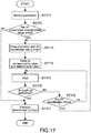
- FIG. 16 is a view showing a state in which the area G is touched
- FIG. 17 is a flowchart showing an operation flow of the CPU 11 in this case.
- the function of returning a page to the previous page or reproducing the previous content is assigned to the area G as described above, such a function can be executed, in some applications, also in an area G' adjacent to the area G on the LCD 16, for example.
- the previous photograph or the previous page is displayed when the area G' on the LCD 16 is touched.
- the PC 100 enables the "Back" function, which can be executed in the area G' on the LCD 16, to be executed also in the area G adjacent thereto on the print area 3a, such that the operation target range for executing such a function is extended.
- the CPU 11 detects a touchdown with respect to the print area 3a (Step 171), and then determines whether or not the XY coordinates of the touch area are located within the target area of the edge access function (Step 172).
- the CPU 11 draws a ripple-like animation A as shown in FIG. 16 with the XY coordinates of the touch position being an origin and displays it on the LCD 16 (Step 173).
- the CPU 11 reads the corresponding table and determines a function corresponding to such an area (function of returning in the case of FIG. 16 ) (Step 174).
- the CPU 11 waits for a touch-up operation (Step 175).
- the CPU 11 executes the determined function (Step 177).
- Step 176 the touch-up is not detected in Step 176 and movement of the XY coordinates of the touch position is detected (Yes in Step 178), the CPU 11 returns to Step 173 and draws the above-mentioned ripple-like animation with the XY coordinates after the movement being an origin.
- the CPU 11 realizes a feedback easy for the user to understand.
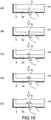
- FIG. 18 is a view showing a display flow of the ripple-like animation. As shown in the parts A to E of FIG. 18 , the ripple-like animation is drawn to become larger with the touch position being the center as time elapses after the user has touched the print area 3a.
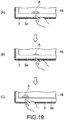
- FIGS. 19 and 20 are views showing a display flow of an animation in the case where after the touchdown with respect to the print area 3a, the touch position is moved.
- the touch position is first moved downwardly, and then moved to the left-hand direction.
- the touch position is gradually moved to the right-hand direction.
- the CPU 11 detects the touch position after each movement and draws an animation with the XY coordinates of the touch position after the movement being an origin as described above.
- the PC 100 can also perform an auditory feedback using sound effects through the speaker.
- they are grouped based on meanings of cooperating functions, such as normal reaction, special use, event generation, event end, enlargement, reduction, and invalidation, and, by using musical images and operations corresponding thereto, it is possible to realize a feedback easy to understand.
- the PC 100 can also perform displaying in OSD (On-Screen Display) as another example of the visual feedback. For example, when the area G is touched, the PC 100 can also display OSD of "Back" on the LCD 16.
- OSD On-Screen Display
- the user can invalidate them on the setting screen or the like.
- the animation and OSD are not desired to be displayed, for example, during viewing a film, it is possible to set them not to be displayed.
- the PC 100 can extend the operation range of the touch operation target displayed on the LCD 16 up to the outside (print area 3a) of the valid display area of the LCD 16, to thereby improve touch operability.
- the present disclosure is not limited to the above-mentioned embodiment, and can be appropriately modified without departing from the gist of the present disclosure.
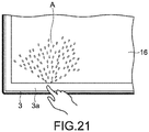
- the kind of animations is not limited thereto.
- the XY coordinates of the touch position being the origin
- an animation that looks as if a spray of water is made upwardly on the LCD 16 may be displayed.
- the button and the like regarding the edge access function are clearly indicated by printing in the print area 3a, they may be clearly indicated by carving instead of printing.
- the user may be allowed to customize and order arbitrary printing or carving, which is designated by the user via the Internet or the like.
- an activation shortcut of an arbitrary program and a new function may be assigned to the print area 3a.
- the user can add a new edge access function, for example, by rewriting an arbitrary button or character with a paint-stick and assigning software to the rewritten area by the system of the above-mentioned programmable power key.
- the area A to which the function of closing the window of the print area 3a is assigned is not subjected to printing or carving of the character, button, or the like indicating it, such printing or carving may be performed. That is the case with the area D and the area F, to which the functions of "Next" and "Back” are assigned, and the like.
- the edge access function is used for the operations with respect to the software or utility software installed into the PC 100, it may be used for other applications.
- the edge access function may be assigned to the commercial label. That is, to the area, onto which the commercial label of the print area 3a is attached, a function of linking to a web site of its company on the Internet or the like may be assigned. By touching such an area, a connection to the Internet may be established and the web site may be displayed on the LCD 16.
- the third party side it is possible for the third party side to provide a more effective advertisement, and it is also possible for the PC vendor to charge the third party side for discount charge of the advertisement fee of such an advertisement.
- the edge access function is executed with respect to the browser or various-content reproduction application
- it can be similarly applied to various other applications.
- a dynamic operation by two or more users becomes possible.
- the users do not need to touch the executed game screen, and hence the screen can be widely used as the screen is not obstructed by the hands.
- the PC 100 has an optical touch panel function through the optical touch sensor unit 20, it is also possible to use other touch panel systems including a resistive system, a capacitance system, an electromagnetic induction system, a matrix switch system, a surface acoustic wave system, and the like.
- a touch to the glass plate 3 having an area larger than that of the LCD 16 is detected, a touch to the LCD 16 may be detected by a touch panel provided integrally with it and a touch to the area corresponding to the print area 3a may be detected by a touch sensor provided in the frame 4 surrounding the LCD 16, for example.
- the present disclosure can be similarly applied to any other information processing apparatuses including a desktop type PC, a laptop type PC, a tablet type PC, a cell phone, a smart phone, a PDA (Personal Digital Assistant), an electronic book terminal, an electronic dictionary, a PVR (Personal Video Recorder), a digital still camera, a digital video camera, a television apparatus, a game machine, a car navigation apparatus, and the like.
- a desktop type PC a laptop type PC, a tablet type PC
- a cell phone a smart phone
- PDA Personal Digital Assistant
- an electronic book terminal an electronic dictionary
- a PVR Personal Video Recorder
- digital still camera a digital video camera
- television apparatus a game machine
- a car navigation apparatus and the like.
Landscapes
- Engineering & Computer Science (AREA)
- General Engineering & Computer Science (AREA)
- Theoretical Computer Science (AREA)
- Human Computer Interaction (AREA)
- Physics & Mathematics (AREA)
- General Physics & Mathematics (AREA)
- Computer Hardware Design (AREA)
- User Interface Of Digital Computer (AREA)
- Position Input By Displaying (AREA)
Applications Claiming Priority (2)
| Application Number | Priority Date | Filing Date | Title |
|---|---|---|---|
| JP2010282955A JP2012133453A (ja) | 2010-12-20 | 2010-12-20 | 情報処理装置、情報処理方法及びプログラム |
| EP11186164.7A EP2466442B1 (en) | 2010-12-20 | 2011-10-21 | Information processing apparatus and information processing method |
Related Parent Applications (2)
| Application Number | Title | Priority Date | Filing Date |
|---|---|---|---|
| EP11186164.7A Division-Into EP2466442B1 (en) | 2010-12-20 | 2011-10-21 | Information processing apparatus and information processing method |
| EP11186164.7A Division EP2466442B1 (en) | 2010-12-20 | 2011-10-21 | Information processing apparatus and information processing method |
Publications (1)
| Publication Number | Publication Date |
|---|---|
| EP3418876A1 true EP3418876A1 (en) | 2018-12-26 |
Family
ID=44905546
Family Applications (2)
| Application Number | Title | Priority Date | Filing Date |
|---|---|---|---|
| EP18183557.0A Ceased EP3418876A1 (en) | 2010-12-20 | 2011-10-21 | Information processing apparatus and information processing method |
| EP11186164.7A Not-in-force EP2466442B1 (en) | 2010-12-20 | 2011-10-21 | Information processing apparatus and information processing method |
Family Applications After (1)
| Application Number | Title | Priority Date | Filing Date |
|---|---|---|---|
| EP11186164.7A Not-in-force EP2466442B1 (en) | 2010-12-20 | 2011-10-21 | Information processing apparatus and information processing method |
Country Status (6)
| Country | Link |
|---|---|
| US (1) | US10955958B2 (enExample) |
| EP (2) | EP3418876A1 (enExample) |
| JP (1) | JP2012133453A (enExample) |
| CN (2) | CN102609180A (enExample) |
| BR (1) | BRPI1105509A2 (enExample) |
| RU (1) | RU2011150470A (enExample) |
Families Citing this family (33)
| Publication number | Priority date | Publication date | Assignee | Title |
|---|---|---|---|---|
| US8018440B2 (en) | 2005-12-30 | 2011-09-13 | Microsoft Corporation | Unintentional touch rejection |
| US8261213B2 (en) | 2010-01-28 | 2012-09-04 | Microsoft Corporation | Brush, carbon-copy, and fill gestures |
| US9411504B2 (en) | 2010-01-28 | 2016-08-09 | Microsoft Technology Licensing, Llc | Copy and staple gestures |
| US9519356B2 (en) | 2010-02-04 | 2016-12-13 | Microsoft Technology Licensing, Llc | Link gestures |
| US9965165B2 (en) | 2010-02-19 | 2018-05-08 | Microsoft Technology Licensing, Llc | Multi-finger gestures |
| US9367205B2 (en) | 2010-02-19 | 2016-06-14 | Microsoft Technolgoy Licensing, Llc | Radial menus with bezel gestures |
| US9454304B2 (en) | 2010-02-25 | 2016-09-27 | Microsoft Technology Licensing, Llc | Multi-screen dual tap gesture |
| CN105404465A (zh) * | 2012-02-29 | 2016-03-16 | 中兴通讯股份有限公司 | 一种触摸操作的处理方法及移动终端 |
| JP6049334B2 (ja) * | 2012-07-12 | 2016-12-21 | キヤノン株式会社 | 検出装置、検出方法及びプログラム |
| WO2014017831A2 (ko) * | 2012-07-25 | 2014-01-30 | Park Chul | 터치패널을 갖는 개인휴대단말기의 작동방법 |
| CN103577029B (zh) * | 2012-07-27 | 2016-09-28 | 鸿富锦精密工业(武汉)有限公司 | 应用程序控制系统及方法 |
| US9582122B2 (en) | 2012-11-12 | 2017-02-28 | Microsoft Technology Licensing, Llc | Touch-sensitive bezel techniques |
| KR101407329B1 (ko) * | 2012-11-16 | 2014-06-16 | 선문대학교 산학협력단 | 터치 화면을 구비하는 디스플레이 장치 및 그의 화면 제어 방법 |
| EP2926220A1 (en) | 2012-11-27 | 2015-10-07 | Thomson Licensing | Adaptive virtual keyboard |
| EP2926236A1 (en) | 2012-11-27 | 2015-10-07 | Thomson Licensing | Adaptive virtual keyboard |
| JP2014178944A (ja) * | 2013-03-15 | 2014-09-25 | Nec Casio Mobile Communications Ltd | 入力装置及びプログラム |
| GB2520335B (en) * | 2013-11-18 | 2017-02-22 | Thorn Security | Alarm panel |
| US20150160849A1 (en) * | 2013-12-06 | 2015-06-11 | Microsoft Corporation | Bezel Gesture Techniques |
| US9335905B1 (en) | 2013-12-09 | 2016-05-10 | Google Inc. | Content selection feedback |
| US11010029B2 (en) | 2013-12-19 | 2021-05-18 | Samsung Electronics Co., Ltd. | Display apparatus and method of displaying image by display apparatus |
| US9477337B2 (en) | 2014-03-14 | 2016-10-25 | Microsoft Technology Licensing, Llc | Conductive trace routing for display and bezel sensors |
| JP6246640B2 (ja) | 2014-03-25 | 2017-12-13 | 京セラ株式会社 | 電子機器 |
| JP5792348B1 (ja) * | 2014-04-16 | 2015-10-07 | シャープ株式会社 | 位置入力装置およびタッチパネル |
| TWI553600B (zh) * | 2014-11-28 | 2016-10-11 | 佳世達科技股份有限公司 | 顯示裝置 |
| JP6549976B2 (ja) * | 2015-11-27 | 2019-07-24 | 株式会社ジャパンディスプレイ | タッチ検出装置及びタッチ検出機能付き表示装置 |
| JP6818417B2 (ja) * | 2016-02-22 | 2021-01-20 | キヤノン株式会社 | 表示装置、表示装置の制御方法、及びプログラム |
| US10314222B2 (en) * | 2016-05-09 | 2019-06-11 | Ag Leader Technology, Inc. | Field computer with integrated hidden lightbar for vehicle guidance |
| USD845355S1 (en) | 2016-06-30 | 2019-04-09 | Ag Leader Technology, Inc. | Display with lightbar for vehicle guidance |
| JP6828563B2 (ja) | 2017-04-04 | 2021-02-10 | 富士ゼロックス株式会社 | 入力装置、画像形成装置及びプログラム |
| USD901545S1 (en) * | 2017-10-19 | 2020-11-10 | Cnh Industrial America Llc | Agricultural sprayer overhead information center |
| DE102018209950A1 (de) * | 2018-06-20 | 2019-12-24 | BSH Hausgeräte GmbH | Steuervorrichtung für ein Hausgerät |
| CN111984179A (zh) * | 2020-08-20 | 2020-11-24 | 歌尔科技有限公司 | 一种触控识别方法、装置、设备及存储介质 |
| US11983348B1 (en) * | 2023-03-28 | 2024-05-14 | Dell Products L.P. | Video conferencing monitor with an advanced panel design |
Citations (8)
| Publication number | Priority date | Publication date | Assignee | Title |
|---|---|---|---|---|
| EP0680007A1 (en) * | 1994-04-28 | 1995-11-02 | NCR International, Inc. | A capacitive touch screen shield |
| US5919802A (en) | 1997-12-05 | 1999-07-06 | Princeton University | Methods of preventing and/or treating temporal lobe epilepsy |
| JP2004355593A (ja) | 2003-05-28 | 2004-12-16 | Sanee Denki Kk | 透明タッチパネル |
| US20060238517A1 (en) | 2005-03-04 | 2006-10-26 | Apple Computer, Inc. | Electronic Device Having Display and Surrounding Touch Sensitive Bezel for User Interface and Control |
| US20070165006A1 (en) * | 2005-10-27 | 2007-07-19 | Alps Electric Co., Ltd | Input device and electronic apparatus |
| EP2003538A1 (en) * | 2007-05-15 | 2008-12-17 | High Tech Computer Corp. | Method for operating user interface and recording medium for storing program applying the same |
| WO2009092599A1 (en) * | 2008-01-25 | 2009-07-30 | Sensitive Object | Touch-sensitive panel |
| JP2010282955A (ja) | 2009-05-07 | 2010-12-16 | Panasonic Corp | メタルハライドランプ |
Family Cites Families (30)
| Publication number | Priority date | Publication date | Assignee | Title |
|---|---|---|---|---|
| JPH0695803A (ja) * | 1992-09-17 | 1994-04-08 | Oki Electric Ind Co Ltd | タッチセンサのエラー通知方法 |
| JP2000105671A (ja) * | 1998-05-11 | 2000-04-11 | Ricoh Co Ltd | 座標入力/検出装置および電子黒板システム |
| US6411283B1 (en) * | 1999-05-20 | 2002-06-25 | Micron Technology, Inc. | Computer touch screen adapted to facilitate selection of features at edge of screen |
| AU3416201A (en) * | 2000-02-24 | 2001-09-03 | Pacific Century Cyberworks Japan Co., Ltd. | Image input device, inage input method, image controller, and charge collecting system |
| JP2002140141A (ja) * | 2000-10-31 | 2002-05-17 | Pacific Century Cyberworks Japan Co Ltd | 画面の制御装置及び画面の制御方法 |
| JP4503154B2 (ja) * | 2000-08-09 | 2010-07-14 | 富士通セミコンダクター株式会社 | 描画データ作成方法及び装置 |
| JP2002157086A (ja) * | 2000-11-17 | 2002-05-31 | Seiko Epson Corp | 入力機能付き表示装置およびそれを備える電子機器ならびに入力機能付き表示装置の製造方法 |
| GB2386707B (en) * | 2002-03-16 | 2005-11-23 | Hewlett Packard Co | Display and touch screen |
| JP4652826B2 (ja) * | 2005-01-14 | 2011-03-16 | タッチパネル・システムズ株式会社 | 情報入力装置 |
| CN103336562A (zh) * | 2005-03-04 | 2013-10-02 | 苹果公司 | 多功能手持设备 |
| CN1900888A (zh) * | 2005-07-22 | 2007-01-24 | 鸿富锦精密工业(深圳)有限公司 | 显示装置及其显示控制方法 |
| CN101609383B (zh) * | 2006-03-03 | 2014-08-06 | 苹果公司 | 具有显示器和用于用户界面及控制的周围触摸敏感边框的电子设备 |
| US20070247434A1 (en) * | 2006-04-19 | 2007-10-25 | Cradick Ryan K | Method, apparatus, and computer program product for entry of data or commands based on tap detection |
| JP4930044B2 (ja) * | 2006-12-26 | 2012-05-09 | ソニー株式会社 | 表示装置 |
| JP4982293B2 (ja) * | 2007-08-08 | 2012-07-25 | 株式会社日立製作所 | 画面表示装置 |
| TWI375161B (en) * | 2007-10-03 | 2012-10-21 | Htc Corp | Hand-held electronic device |
| US8154523B2 (en) * | 2007-12-13 | 2012-04-10 | Eastman Kodak Company | Electronic device, display and touch-sensitive user interface |
| US8413075B2 (en) * | 2008-01-04 | 2013-04-02 | Apple Inc. | Gesture movies |
| US20110074738A1 (en) * | 2008-06-18 | 2011-03-31 | Beijing Irtouch Systems Co., Ltd. | Touch Detection Sensing Apparatus |
| KR101613919B1 (ko) * | 2008-09-25 | 2016-04-20 | 엘지전자 주식회사 | 이동 단말기 |
| JP2010191892A (ja) * | 2009-02-20 | 2010-09-02 | Sony Corp | 情報処理装置、表示制御方法、及びプログラム |
| US20120044143A1 (en) * | 2009-03-25 | 2012-02-23 | John David Newton | Optical imaging secondary input means |
| US8134539B2 (en) * | 2009-03-30 | 2012-03-13 | Eastman Kodak Company | Digital picture frame having near-touch and true-touch |
| WO2010126072A1 (ja) * | 2009-04-28 | 2010-11-04 | 日本電気株式会社 | タッチパネル、タッチパネルの製造方法及び電子機器 |
| GB2484232B (en) * | 2009-07-23 | 2015-10-28 | Hewlett Packard Development Co | Display with an optical sensor |
| CN201629785U (zh) * | 2009-12-24 | 2010-11-10 | 联想(北京)有限公司 | 一种手机 |
| US8799827B2 (en) * | 2010-02-19 | 2014-08-05 | Microsoft Corporation | Page manipulations using on and off-screen gestures |
| US9965165B2 (en) * | 2010-02-19 | 2018-05-08 | Microsoft Technology Licensing, Llc | Multi-finger gestures |
| US9310994B2 (en) * | 2010-02-19 | 2016-04-12 | Microsoft Technology Licensing, Llc | Use of bezel as an input mechanism |
| TWM527823U (zh) | 2016-05-31 | 2016-09-01 | Sky Sunlight Co Ltd | 具著色氣球之裝飾卡片 |
-
2010
- 2010-12-20 JP JP2010282955A patent/JP2012133453A/ja active Pending
-
2011
- 2011-10-21 EP EP18183557.0A patent/EP3418876A1/en not_active Ceased
- 2011-10-21 EP EP11186164.7A patent/EP2466442B1/en not_active Not-in-force
- 2011-12-12 RU RU2011150470/02A patent/RU2011150470A/ru unknown
- 2011-12-13 CN CN2011104215988A patent/CN102609180A/zh active Pending
- 2011-12-13 BR BRPI1105509-0A patent/BRPI1105509A2/pt not_active IP Right Cessation
- 2011-12-13 CN CN2011205255102U patent/CN202976015U/zh not_active Expired - Lifetime
- 2011-12-14 US US13/325,625 patent/US10955958B2/en not_active Expired - Fee Related
Patent Citations (8)
| Publication number | Priority date | Publication date | Assignee | Title |
|---|---|---|---|---|
| EP0680007A1 (en) * | 1994-04-28 | 1995-11-02 | NCR International, Inc. | A capacitive touch screen shield |
| US5919802A (en) | 1997-12-05 | 1999-07-06 | Princeton University | Methods of preventing and/or treating temporal lobe epilepsy |
| JP2004355593A (ja) | 2003-05-28 | 2004-12-16 | Sanee Denki Kk | 透明タッチパネル |
| US20060238517A1 (en) | 2005-03-04 | 2006-10-26 | Apple Computer, Inc. | Electronic Device Having Display and Surrounding Touch Sensitive Bezel for User Interface and Control |
| US20070165006A1 (en) * | 2005-10-27 | 2007-07-19 | Alps Electric Co., Ltd | Input device and electronic apparatus |
| EP2003538A1 (en) * | 2007-05-15 | 2008-12-17 | High Tech Computer Corp. | Method for operating user interface and recording medium for storing program applying the same |
| WO2009092599A1 (en) * | 2008-01-25 | 2009-07-30 | Sensitive Object | Touch-sensitive panel |
| JP2010282955A (ja) | 2009-05-07 | 2010-12-16 | Panasonic Corp | メタルハライドランプ |
Also Published As
| Publication number | Publication date |
|---|---|
| EP2466442B1 (en) | 2019-01-02 |
| RU2011150470A (ru) | 2013-06-20 |
| JP2012133453A (ja) | 2012-07-12 |
| US10955958B2 (en) | 2021-03-23 |
| CN202976015U (zh) | 2013-06-05 |
| CN102609180A (zh) | 2012-07-25 |
| EP2466442A3 (en) | 2016-02-24 |
| US20120154408A1 (en) | 2012-06-21 |
| BRPI1105509A2 (pt) | 2013-04-02 |
| EP2466442A2 (en) | 2012-06-20 |
Similar Documents
| Publication | Publication Date | Title |
|---|---|---|
| EP2466442B1 (en) | Information processing apparatus and information processing method | |
| TWI455011B (zh) | 觸控顯示裝置及條件式改變顯示範圍之方法 | |
| US20090315841A1 (en) | Touchpad Module which is Capable of Interpreting Multi-Object Gestures and Operating Method thereof | |
| JP2004038927A (ja) | ディスプレイ及びタッチスクリーン | |
| JP6225911B2 (ja) | 情報処理装置、情報処理方法及びプログラム | |
| CN110716687B (zh) | 在便携设备上显示画面的方法和装置 | |
| KR102190904B1 (ko) | 윈도우 제어 방법 및 이를 지원하는 전자장치 | |
| CN104679362A (zh) | 触控装置及其控制方法 | |
| CN101349944A (zh) | 手势引导系统及以触控手势控制计算机系统的方法 | |
| CN108064371A (zh) | 一种柔性显示屏的控制方法及装置 | |
| CN101482790A (zh) | 可于两显示元件上转移对象的电子装置及其控制方法 | |
| TW201426506A (zh) | 具有快捷啟動功能之電子裝置及其控制方法 | |
| TWI448957B (zh) | 電子裝置 | |
| CN104035606A (zh) | 触控面板的操作方法与电子装置 | |
| KR102152383B1 (ko) | 단말 장치 및 그 제어 방법 | |
| JP2009098990A (ja) | 表示装置 | |
| US11188224B2 (en) | Control method of user interface and electronic device | |
| US20140085340A1 (en) | Method and electronic device for manipulating scale or rotation of graphic on display | |
| JP6352626B2 (ja) | 表示装置及びアンロック方法 | |
| JP2016035705A (ja) | 表示装置、表示制御方法、及び表示制御プログラム | |
| JP5330175B2 (ja) | タッチパッド、情報処理端末、タッチパッドの制御方法、及びプログラム | |
| JP2016035706A (ja) | 表示装置、表示制御方法、及び表示制御プログラム | |
| EP4697140A1 (en) | Method and system for dual-mode touch and touchless gesture control of a computer device | |
| JP5284419B2 (ja) | 情報処理装置および表示方法 | |
| CN103902085B (zh) | 具有边框的触控屏幕的边缘触控方法 |
Legal Events
| Date | Code | Title | Description |
|---|---|---|---|
| PUAI | Public reference made under article 153(3) epc to a published international application that has entered the european phase |
Free format text: ORIGINAL CODE: 0009012 |
|
| STAA | Information on the status of an ep patent application or granted ep patent |
Free format text: STATUS: REQUEST FOR EXAMINATION WAS MADE |
|
| 17P | Request for examination filed |
Effective date: 20180813 |
|
| AC | Divisional application: reference to earlier application |
Ref document number: 2466442 Country of ref document: EP Kind code of ref document: P |
|
| AK | Designated contracting states |
Kind code of ref document: A1 Designated state(s): AL AT BE BG CH CY CZ DE DK EE ES FI FR GB GR HR HU IE IS IT LI LT LU LV MC MK MT NL NO PL PT RO RS SE SI SK SM TR |
|
| STAA | Information on the status of an ep patent application or granted ep patent |
Free format text: STATUS: EXAMINATION IS IN PROGRESS |
|
| 17Q | First examination report despatched |
Effective date: 20200514 |
|
| RAP3 | Party data changed (applicant data changed or rights of an application transferred) |
Owner name: SONY GROUP CORPORATION |
|
| STAA | Information on the status of an ep patent application or granted ep patent |
Free format text: STATUS: THE APPLICATION HAS BEEN REFUSED |
|
| 18R | Application refused |
Effective date: 20211209 |