EP3394497B1 - Schmierstoffpresse, schmierstoffpressen-set und verwendung einer kartusche bei einer schmierstoffpresse - Google Patents
Schmierstoffpresse, schmierstoffpressen-set und verwendung einer kartusche bei einer schmierstoffpresse Download PDFInfo
- Publication number
- EP3394497B1 EP3394497B1 EP16822903.7A EP16822903A EP3394497B1 EP 3394497 B1 EP3394497 B1 EP 3394497B1 EP 16822903 A EP16822903 A EP 16822903A EP 3394497 B1 EP3394497 B1 EP 3394497B1
- Authority
- EP
- European Patent Office
- Prior art keywords
- cartridge
- lubricant
- press
- lubricant press
- top side
- Prior art date
- Legal status (The legal status is an assumption and is not a legal conclusion. Google has not performed a legal analysis and makes no representation as to the accuracy of the status listed.)
- Active
Links
Images

Classifications
-
- B—PERFORMING OPERATIONS; TRANSPORTING
- B01—PHYSICAL OR CHEMICAL PROCESSES OR APPARATUS IN GENERAL
- B01D—SEPARATION
- B01D27/00—Cartridge filters of the throw-away type
- B01D27/04—Cartridge filters of the throw-away type with cartridges made of a piece of unitary material, e.g. filter paper
- B01D27/06—Cartridge filters of the throw-away type with cartridges made of a piece of unitary material, e.g. filter paper with corrugated, folded or wound material
-
- F—MECHANICAL ENGINEERING; LIGHTING; HEATING; WEAPONS; BLASTING
- F16—ENGINEERING ELEMENTS AND UNITS; GENERAL MEASURES FOR PRODUCING AND MAINTAINING EFFECTIVE FUNCTIONING OF MACHINES OR INSTALLATIONS; THERMAL INSULATION IN GENERAL
- F16N—LUBRICATING
- F16N3/00—Devices for supplying lubricant by manual action
-
- B—PERFORMING OPERATIONS; TRANSPORTING
- B01—PHYSICAL OR CHEMICAL PROCESSES OR APPARATUS IN GENERAL
- B01D—SEPARATION
- B01D29/00—Filters with filtering elements stationary during filtration, e.g. pressure or suction filters, not covered by groups B01D24/00 - B01D27/00; Filtering elements therefor
- B01D29/11—Filters with filtering elements stationary during filtration, e.g. pressure or suction filters, not covered by groups B01D24/00 - B01D27/00; Filtering elements therefor with bag, cage, hose, tube, sleeve or like filtering elements
- B01D29/112—Ring shaped filters wherein both opposite axial sides are opened and the axial length is shorter than the diameter, e.g. as used in hydraulic transmission systems
-
- B—PERFORMING OPERATIONS; TRANSPORTING
- B01—PHYSICAL OR CHEMICAL PROCESSES OR APPARATUS IN GENERAL
- B01D—SEPARATION
- B01D35/00—Filtering devices having features not specifically covered by groups B01D24/00 - B01D33/00, or for applications not specifically covered by groups B01D24/00 - B01D33/00; Auxiliary devices for filtration; Filter housing constructions
- B01D35/02—Filters adapted for location in special places, e.g. pipe-lines, pumps, stop-cocks
- B01D35/027—Filters adapted for location in special places, e.g. pipe-lines, pumps, stop-cocks rigidly mounted in or on tanks or reservoirs
-
- F—MECHANICAL ENGINEERING; LIGHTING; HEATING; WEAPONS; BLASTING
- F16—ENGINEERING ELEMENTS AND UNITS; GENERAL MEASURES FOR PRODUCING AND MAINTAINING EFFECTIVE FUNCTIONING OF MACHINES OR INSTALLATIONS; THERMAL INSULATION IN GENERAL
- F16N—LUBRICATING
- F16N13/00—Lubricating-pumps
- F16N13/02—Lubricating-pumps with reciprocating piston
- F16N13/06—Actuation of lubricating-pumps
- F16N13/08—Actuation of lubricating-pumps by hand or foot
-
- F—MECHANICAL ENGINEERING; LIGHTING; HEATING; WEAPONS; BLASTING
- F16—ENGINEERING ELEMENTS AND UNITS; GENERAL MEASURES FOR PRODUCING AND MAINTAINING EFFECTIVE FUNCTIONING OF MACHINES OR INSTALLATIONS; THERMAL INSULATION IN GENERAL
- F16N—LUBRICATING
- F16N19/00—Lubricant containers for use in lubricators or lubrication systems
-
- F—MECHANICAL ENGINEERING; LIGHTING; HEATING; WEAPONS; BLASTING
- F16—ENGINEERING ELEMENTS AND UNITS; GENERAL MEASURES FOR PRODUCING AND MAINTAINING EFFECTIVE FUNCTIONING OF MACHINES OR INSTALLATIONS; THERMAL INSULATION IN GENERAL
- F16N—LUBRICATING
- F16N23/00—Special adaptations of check valves
-
- F—MECHANICAL ENGINEERING; LIGHTING; HEATING; WEAPONS; BLASTING
- F16—ENGINEERING ELEMENTS AND UNITS; GENERAL MEASURES FOR PRODUCING AND MAINTAINING EFFECTIVE FUNCTIONING OF MACHINES OR INSTALLATIONS; THERMAL INSULATION IN GENERAL
- F16N—LUBRICATING
- F16N3/00—Devices for supplying lubricant by manual action
- F16N3/10—Devices for supplying lubricant by manual action delivering grease
- F16N3/12—Grease guns
-
- B—PERFORMING OPERATIONS; TRANSPORTING
- B01—PHYSICAL OR CHEMICAL PROCESSES OR APPARATUS IN GENERAL
- B01D—SEPARATION
- B01D2201/00—Details relating to filtering apparatus
- B01D2201/12—Pleated filters
-
- F—MECHANICAL ENGINEERING; LIGHTING; HEATING; WEAPONS; BLASTING
- F16—ENGINEERING ELEMENTS AND UNITS; GENERAL MEASURES FOR PRODUCING AND MAINTAINING EFFECTIVE FUNCTIONING OF MACHINES OR INSTALLATIONS; THERMAL INSULATION IN GENERAL
- F16H—GEARING
- F16H57/00—General details of gearing
- F16H57/04—Features relating to lubrication or cooling or heating
- F16H57/0402—Cleaning of lubricants, e.g. filters or magnets
- F16H57/0404—Lubricant filters
Definitions
- the application relates to a lubricant press with a press head which has a cartridge receptacle, the cartridge receptacle having an end wall in which a passage to a high pressure chamber opens, a plunger being movably arranged in the high pressure chamber which is in actuation connection with a hand lever attached to the press head stands, and wherein the high pressure chamber opens into an outlet opening, and with a follower piston that can be inserted into a cartridge.
- the invention further relates to a lubricant press set with a lubricant press, in particular as described, and with a cartridge, the cartridge having a cartridge sleeve enclosing a filling volume, the follower piston of the lubricant press being movably inserted into the cartridge sleeve in order to close off the filling volume.
- the invention finally relates to a use of a cartridge in a lubricant press n-set (26).
- Lubricant presses are known and are used, for example, to deliver lubricant from a cartridge to places that may be difficult to access.
- a grease gun with a press head a press pipe detachably coupled to the press head and a connection formed on the press head for a cartridge accommodated in the press pipe is known, it being provided that the press pipe in the area its rear end facing away from the press head forms a stop for the cartridge, the axial position of which is adapted to the length of the cartridge in such a way that the cartridge holds in a position resting against the end.
- the DE 20 2012 103 334 U1 discloses a stamp for a grease gun with a disk-shaped shut-off element which is designed to be guided in a closing manner in a tube of the grease gun and to be sealed with a circumferential rubber-elastic seal on the inner surface of the tube, it being provided that the shut-off element has two disks which the seal clamped between them and the distance between them can be adjusted by means of a tensioning device.
- the invention is based on the object of improving the performance properties of a lubricant press.
- a top of the follower piston facing the end wall in the position of use has a contour that is designed to match a contour of the end wall so that the top of the follower piston at least in a partial area on the Closing wall can be applied over a large area.
- the advantage here is that a remaining dead volume can be made as small as possible. In particular, residues that had previously formed in cavities between the press head and the follower piston in its end position can thus be avoided.
- Standard cartridges can thus also be used in a lubricant-saving manner, which do not have any special adaptation to a specific press head and in particular no screw connection for a passage on their upper side.
- an inlet opening of the passage is formed at a point of the end wall which is furthest in the press head in a cartridge insertion direction which is defined by the cartridge receptacle. This means that the formation of lubricant residues in the cartridge holder, for example in pockets, can be avoided.
- the end wall is flat at least in the partial area. This means that obstacles on which lubricant residues can collect can be avoided in some areas. It is particularly favorable if the end wall is flat. This makes it easy to achieve that the inlet opening is at a highest point - viewed in the insertion or conveying direction - can be arranged. Alternatively or in addition, it can be provided that the upper side is flat. A dead volume at the top, in which lubricant residues could collect, can thus be avoided. It is particularly favorable if the sub-area and the surface are designed to be flat and matched to one another. In this way, the surface can be laid flat on the partial area in a simple manner in order to completely displace lubricant.
- the passage in the end wall is at least partially arranged outside the sub-area.
- the advantage here is that the passage can be arranged behind a remaining dead volume in the cartridge receptacle. It can thus be achieved that the lubricant in this dead volume can be at least partially exchanged after a new cartridge has been inserted. It is also advantageous that the passage can be arranged laterally in relation to a partial area which is preferably formed centrally in the cartridge receptacle, whereby a long path can be made available for a plunger without increasing the external dimension.
- the follower piston has a shoulder running around the top.
- the follower piston can be designed so that the top can reach through a removal opening of a cartridge.
- a dead volume that is to say a remaining volume when the cartridge is used up, at which the follower piston has reached an end position, can be reduced in the cartridge receptacle.
- the shoulder has an annular shoulder surface.
- the shoulder surface can be parallel be aligned to the top.
- the shape of the follower piston can thus be designed to match a removal opening of a standard cartridge, in which the removal opening is formed by a circumferential collar protruding inward from the cartridge sleeve.
- the follower piston is designed without any openings. This means that guide rods can be dispensed with and the follower piston can be designed in a simple, sealed manner.
- the follower piston has a circumferential sealing lip. An annular slot between the follower piston and the cartridge sleeve can thus be sealed.
- an internal thread is formed on the cartridge receptacle.
- a receiving tube is screwed into the cartridge receptacle, which is designed to be open at a free end.
- a standard cartridge which has a circumferential collar on its outside, can thus be easily detachably fastened in the cartridge receptacle. It is not necessary to form a thread on the cartridge.
- the receiving tube offers mechanical protection in that it can be made longer than the cartridge, for example. Due to the open design at the lower free end, the receiving tube simply allows air to penetrate to compensate for the advancing piston.
- a sealing ring can be inserted into the cartridge receptacle at a position at which the cartridge sleeve contacts the end wall.
- a check valve is arranged in the passage.
- a piston pump is connected downstream of the passage. This means that lubricant can be withdrawn even when the follower piston is not pressurized.
- the piston pump is preferably equipped with a hand lever in order to be able to operate a plunger manually.
- the features of the subordinate claim directed to a lubricant press set are proposed according to the invention.
- the invention proposes that a shape of the follower piston is matched to the cartridge in such a way that the filling volume of the cartridge sleeve with the follower piston can be completely emptied.
- the advantage here is that the formation of residues of non-removable lubricant in the used cartridge can be prevented by simple measures. This increases the yield of the cartridge and thus improves the properties of the lubricant gun.
- the filling volume of the cartridge sleeve is provided by a constriction forming extraction opening is limited and that an outer diameter of the top of the follower piston is matched to an inner diameter of the extraction opening.
- the removal opening is preferably closed before first use and is only opened shortly before first use, for example by tearing off a closure.
- the follower piston can be designed with a large surface area in order to cover the largest possible partial area on the end wall. A small dead volume can thus be formed.
- a height of a shoulder running around the top, for example the already mentioned top, of the follower piston is matched to a protrusion of the cartridge sleeve over the removal opening. It is thus easy to achieve that the follower piston in its end position lies flat against the partial area.
- the height can be selected to be greater than the protrusion in order to provide space for a seal.
- annular shoulder surface of a shoulder running around the upper side is matched to an annular inner surface formed between the removal opening and the cartridge sleeve. It is thus easy to prevent residues from remaining in the used cartridge at the constriction.
- the follower piston is arranged in the cartridge sleeve without being acted upon.
- the follower piston thus moves in the cartridge sleeve solely due to a negative pressure applied to the cartridge receptacle through the passage.
- a seal between the cartridge sleeve and the follower piston is thus simple trainable.
- the follower piston can be arranged in the cartridge sleeve without being connected to the press head.
- additional moving parts for actuating or acting on the follower piston from the outside can be dispensed with.
- the follower piston can alternatively or additionally be arranged in a removable manner in the cartridge sleeve. The advantage here is that the follower piston can be reused.
- the cartridge is opened on the top and that before lubricant is removed from the Cartridge, the follower piston of the lubricant press is inserted into the cartridge on the underside in order to close off a filling volume in the cartridge and that, after the cartridge has been completely emptied, the follower piston lies flat with its upper side on the partial area.
- the advantage here is that the cartridge can be completely emptied in a simple manner.
- the follower piston can be inserted into the cartridge receptacle before or after the cartridge is inserted.
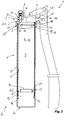
- Fig. 1 shows the cartridge 4 in a state in which a filling volume 5 is filled with a lubricant
- Fig. 2 shows the used and completely emptied cartridge 4.
- An end wall 6 is formed in the cartridge receptacle 3.
- the end wall 6 has a passage 7 which opens into a high pressure chamber 8.
- a plunger 9 of a piston pump 10 is arranged in the high-pressure chamber 8 and can be moved from the outside in the high-pressure chamber 8 with a hand lever 11.
- the high-pressure chamber 8 has an outlet opening 12 through which lubricant emerges from the filling volume 5.
- the lubricant press 4 also has a follower piston 13, which can be inserted into an open end 14 - with its top 15 first.
- the top 15 is thus arranged facing the end wall 6 in the position of use and has a contour that fits is formed into a contour of the end wall 6. It can thus be achieved that the upper side 15 of the follower piston 13 rests flat against the end wall 6 in a partial area 16 when the cartridge 4 is used up ( Fig. 2 ). No lubricant residues therefore remain on this sub-area 16.
- the passage 7 is arranged in such a way that an inlet opening 17 of the passage 7 is formed at a point 18 of the end wall 6 that is furthest in the press head.
- the inlet opening 19 is thus at the rearmost point in a cartridge insertion direction 19 predetermined by the cartridge receptacle 3 - in the exemplary embodiment together with other points on the end wall 6. There are therefore no pockets in which lubricant residues could collect.
- the end wall 6 is designed to be flat to match the top 15.
- the passage 7 is partially arranged outside the sub-area 15 directly in front of the remaining dead volume 20 in the cartridge receptacle 3. After the used cartridge 4 has been replaced with a new one, this dead volume 20 is thus at least partially removed first.
- the lateral arrangement of the passage 7 also offers sufficient space for the arrangement of the elongated high-pressure chamber 8 within the press head 2.
- a shoulder 21 is formed on the follower piston 13, which extends around the top side 15 and delimits the top side 16.
- the shoulder 21 thus forms a shoulder surface 31 which is ring-shaped and is oriented parallel to the upper side 15. This shape is matched to the cartridge 4, as more precisely is explained.
- the follower piston 13 is designed without a perforation without a guide rod to be arranged in the cartridge 4 and has an annular, circumferential sealing lip 22.
- the sealing lip 22 thus seals an annular slot 37 between the follower piston 13 and a cartridge sleeve 27.
- An internal thread 23 is formed on the cartridge receptacle 3, into which a receiving tube 24 is screwed into the cartridge receptacle 3 in order to hold the cartridge on a collar 25.
- the receiving tube 24 is designed to be open at its free end 33.
- a check valve 34 is arranged in the passage 7 in order to prevent a backflow of lubricant into the piston receptacle 3 when the piston pump 10 connected downstream of the passage 7 is actuated.
- the lubricant press 1 thus forms a lubricant press set 26 with the exchangeable cartridge 4.
- the filling volume 5 is formed in the cartridge sleeve 27 and filled with lubricant.
- the follower piston 13 is inserted movably into the cartridge sleeve 27 as described and migrates towards the end wall 6 with a withdrawal of lubricant until it rests flat in the partial area 16.
- a shape of the follower piston 13 is matched to the cartridge 4 so that the filling volume 5 of the cartridge sleeve 27 with the follower piston 13 can be completely emptied.
- the filling volume 5 of the cartridge sleeve 27 is limited by a removal opening 28 which forms a constriction in the cartridge sleeve 27.
- the removal opening 28 is closed before first use.
- An outer diameter of the upper side 15 of the follower piston 13 is matched to an inner diameter of the removal opening 28 in order to achieve the adaptation of the shape, that is to say is of the same size here. Furthermore, a height 29 of the shoulder 21 is matched to a protrusion 30 of the cartridge sleeve 4 over the removal opening 28, that is to say is of the same size here except for the height of a seal 35.
- the shoulder surface 31 is finally matched to an annular inner surface 32, that is to say is of the same size here, this inner surface 32 being formed on an inwardly protruding collar 36 between the removal opening 28 and the cartridge sleeve 31.
- the uninterrupted follower piston 5 is not acted upon and is not connected to the press head 2 and is therefore arranged in the cartridge sleeve 27 so that it can be removed.
- the follower piston 5 is thus sucked in by the lubricant alone and does not itself exert any pressure.
- the cartridge 4 is thus opened on the top, and the follower piston 13 is inserted into the cartridge 4 on the underside. This completes the filling volume 5 in the cartridge 4. After the cartridge 4 has been completely emptied, the upper side 15 of the follower piston 13 rests flat against the partial area 16 of the end wall 6.
- a follower piston 13 which can be inserted into a cartridge 4, and an end wall 6 of a cartridge holder 3 should be placed on top of one another to coordinate the cartridge 4 so that the follower piston 13 in the used cartridge 4 rests flat against the end wall 6.
Landscapes
- Engineering & Computer Science (AREA)
- General Engineering & Computer Science (AREA)
- Mechanical Engineering (AREA)
- Chemical & Material Sciences (AREA)
- Chemical Kinetics & Catalysis (AREA)
- Details Of Reciprocating Pumps (AREA)
- Coating Apparatus (AREA)
- Reciprocating Pumps (AREA)
- Press Drives And Press Lines (AREA)
Description
- Die Anmeldung betrifft eine Schmierstoffpresse mit einem Pressenkopf, der eine Kartuschenaufnahme aufweist, wobei die Kartuschenaufnahme eine Abschlusswand aufweist, in welcher ein Durchlass zu einen Hochdruckraum mündet, wobei in dem Hochdruckraum ein Presskolben beweglich angeordnet ist, der mit einem an dem Pressenkopf angebrachten Handhebel in Betätigungsverbindung steht, und wobei der Hochdruckraum in eine Auslassöffnung mündet, und mit einem in eine Kartusche einsetzbaren Folgekolben.
- Die Erfindung betrifft weiter ein Schmierstoffpressen-Set mit einer Schmierstoffpresse, insbesondere wie beschrieben, und mit einer Kartusche, wobei die Kartusche eine ein Füllvolumen umschließende Kartuschenhülse aufweist, wobei in die Kartuschenhülse der Folgekolben der Schmierstoffpresse beweglich eingesetzt ist, um das Füllvolumen abzuschließen.
- Die Erfindung betrifft schließlich eine Verwendung einer Kartusche bei einer Schmierstoffpresse n-Set (26).
- Schmierstoffpressen sind bekannt und werden beispielsweise verwendet, um Schmierstoff aus einer Kartusche an möglicherweise schwer zugängliche Stellen zu fördern.
- Aus der
DE 20 2013 102 560 U ist eine Fettpresse mit einem Pressenkopf, einem lösbar an den Pressenkopf angekuppelten Pressenrohr und einem an dem Pressenkopf ausgebildeten Anschluss für eine in dem Pressenrohr aufgenommene Kartusche bekannt, wobei vorgesehen ist, dass das Pressenrohr im Bereich seines hinteren, vom Pressenkopf abgewandten Endes ein Anschlag für die Kartusche bildet, dessen axiale Position so an die Länge der Kartusche angepasst ist, dass die Kartusche in einer an dem Abschluss anliegenden Position hält. - Aus der
US 4,168,787 ist eine Fettpresse mit einem Pressenrohr bekannt, bei dem ein Folgekolben in dem Pressenrohr beweglich angeordnet ist und bei der in dem Pressenkopf ein Kolben in einer Kammer vorgesehen ist, welche über ein Ventil mit dem von dem Pressenrohr gebildeten Volumen in Verbindung steht. - Die
DE 20 2012 103 334 U1 offenbart einen Stempel für eine Fettpresse mit einem scheibenförmigen Absperrelement, das dazu ausgebildet ist, schließend in einem Rohr der Fettpresse geführt zu werden und mit einer umlaufenden gummielastischen Dichtung an der Innenfläche des Rohres abzudichten, wobei vorgesehen ist, dass das Absperrelement zwei Scheiben aufweist, die die Dichtung klemmend zwischen sich aufnehmen und deren Abstand mittels einer Spanneinrichtung verstellbar ist. - Aus der
US 4,664,298 ist eine Fettpresse bekannt, bei der durch eine Veränderung der effektiven Länge eines Hebelarms die Fettpresse entweder in einem Hochdruckmodus oder in einem Hochvolumenmodus betreibbar ist. - Der Erfindung liegt die Aufgabe zugrunde, die Gebrauchseigenschaften einer Schmierstoffpresse zu verbessern.
- Zur Lösung der Aufgabe sind erfindungsgemäß die Merkmale des Anspruchs 1 vorgesehen. Insbesondere wird somit bei einer Schmierstoffpresse der eingangs beschriebenen Art erfindungsgemäß vorgeschlagen, dass eine in Gebrauchsstellung der Abschlusswand zugewandte Oberseite des Folgekolbens eine Kontur aufweist, die passend zu einer Kontur der Abschlusswand ausgebildet ist, so dass der Folgekolben mit seiner Oberseite zumindest in einem Teilbereich an der Abschlusswand flächig anlegbar ist. Von Vorteil ist dabei, dass ein verbleibendes Totvolumen so gering wie möglich ausbildbar ist. Insbesondere sind somit Rückstände, die sich bisher in Kavitäten zwischen dem Pressenkopf und dem Folgekolben in dessen Endposition gebildet hatten, vermeidbar. Es sind somit auch Standard-Kartuschen schmierstoffsparend verwendbar, die an ihrer Oberseite keine spezielle Anpassung an einen spezifischen Pressenkopf und insbesondere keinen Schraubanschluss für einen Durchlass aufweisen.
- Bei einer vorteilhaften Ausgestaltung kann vorgesehen sein, dass eine Eintrittsöffnung des Durchlasses an einer in einer Kartuschen-Einsetzrichtung, die durch die Kartuschenaufnahme definiert ist, am weitesten im Pressenkopf liegenden Stelle der Abschlusswand ausgebildet ist. Somit sind Rückstandsbildungen von Schmierstoff in der Kartuschenaufnahme, beispielsweise in Taschen, vermeidbar.
- Bei einer vorteilhaften Ausgestaltung kann vorgesehen sein, dass die Abschlusswand zumindest im Teilbereich eben ausgebildet ist. Somit sind Hindernisse, an denen sich Schmierstoffrückstände ansammeln können, im Teilbereich vermeidbar. Besonders günstig ist es, wenn die Abschlusswand eben ausgebildet ist. Somit ist einfach erreichbar, dass die Eintrittsöffnung an einem höchsten Punkt - in Einsteck- oder Förderrichtung gesehen - angeordnet werden kann. Alternativ oder zusätzlich kann vorgesehen sein, dass die Oberseite eben ausgebildet ist. Somit ist ein Totvolumen an der Oberseite, in welchem sich Schmierstoffrückstände ansammeln könnten, vermeidbar. Besonders günstig ist es, wenn der Teilbereich und die Oberfläche aufeinander abgestimmt eben ausgebildet sind. Somit kann die Oberfläche auf einfache Weise flächig an den Teilbereich angelegt werden, um Schmierstoff vollständig zu verdrängen.
- Bei einer vorteilhaften Ausgestaltung kann vorgesehen sein, dass der Durchlass in der Abschlusswand zumindest teilweise außerhalb des Teilbereichs angeordnet ist. Von Vorteil ist dabei, dass der Durchlass hinter einem verbleibenden Totvolumen in der Kartuschenaufnahme anordenbar ist. Somit ist erreichbar, dass Schmierstoff in diesem Totvolumen nach Einsetzen einer neuen Kartusche zumindest teilweise austauschbar ist. Von Vorteil ist weiter, dass der Durchlass seitlich in Bezug auf einen vorzugsweise mittig in der Kartuschenaufnahme ausgebildeten Teilbereich anordnenbar ist, wodurch ohne Vergrößerung eines Außenmaßes ein langer Weg für einen Presskolben zur Verfügung stellbar ist.
- Bei einer vorteilhaften Ausgestaltung kann vorgesehen sein, dass der Folgekolben eine um die Oberseite umlaufend Schulter aufweist. Von Vorteil ist dabei, dass der Folgekolben so ausgebildet werden kann, dass die Oberseite durch eine Entnahmeöffnung einer Kartusche hindurchgreifen kann. Somit ist ein Totvolumen, also ein verbleibendes Volumen bei aufgebrauchter Kartusche, bei welcher der Folgekolben in einer Endposition gelangt ist, in der Kartuschenaufnahme reduzierbar.
- Besonders günstig ist es dabei, wenn die Schulter eine ringförmige Schulterfläche aufweist. Die Schulterfläche kann parallel zu der Oberseite ausgerichtet sein. Somit ist der Folgekolben passend in seiner Form zu einer Entnahmeöffnung einer Standard-Kartusche ausbildbar, bei welcher die Entnahmeöffnung durch einen nach innen von der Kartuschenhülse abragenden, umlaufenden Kragen ausgebildet ist.
- Bei einer vorteilhaften Ausgestaltung kann vorgesehen sein, dass der Folgekolben durchbrechungsfrei ausgebildet ist. Somit sind Führungsstäbe verzichtbar und der Folgekolben ist einfach abgedichtet ausbildbar.
- Bei einer vorteilhaften Ausgestaltung kann vorgesehen sein, dass der Folgekolben eine umlaufende Dichtlippe aufweist. Somit ist ein Ringschlitz zwischen dem Folgekolben und der Kartuschenhülse abdichtbar.
- Bei einer vorteilhaften Ausgestaltung kann vorgesehen sein, dass an der Kartuschenaufnahme ein Innengewinde ausgebildet ist. Somit ist eine Kartusche einfach in der Kartuschenaufnahme lösbar befestigbar.
- Bei einer vorteilhaften Ausgestaltung kann vorgesehen sein, dass ein Aufnahmerohr in die Kartuschenaufnahme eingeschraubt ist, das an einem freien Ende offen ausgebildet ist. Somit ist eine Standard-Kartusche, die an ihrer Außenseite einen umlaufenden Bund aufweist, einfach lösbar in der Kartuschenaufnahme befestigbar. Eine Ausbildung eines Gewindes an der Kartusche ist nicht erforderlich. Das Aufnahmerohr bietet einen mechanischen Schutz, indem es beispielsweise länger als die Kartusche ausbildbar ist. Durch die offene Ausgestaltung am unteren freien Ende erlaubt das Aufnahmerohr einfach das Eindringen von Luft zum Ausgleich bei fortschreitendem Folgekolben.
- Zur Abdichtung kann in die Kartuschenaufnahme ein Dichtring an an einer Position eingelegt sein, an welcher die Kartuschenhülse die Abschlusswand kontaktiert.
- Bei einer vorteilhaften Ausgestaltung kann vorgesehen sein, dass in dem Durchlass ein Rückschlagventil angeordnet ist. Von Vorteil ist dabei, dass Zurückdrücken des Schmierstoffs in die Kartuschenaufnahme verhinderbar ist.
- Bei einer vorteilhaften Ausgestaltung kann vorgesehen sein, dass dem Durchlass eine Kolbenpumpe nachgeschaltet ist. Somit ist eine Entnahme von Schmierstoff auch bei unbeaufschlagtem Folgekolben erreichbar. Bevorzugt ist die Kolbenpumpe mit einem Handhebel ausgerüstet, um einen Presskolben manuell betätigen zu können.
- Zur Lösung der genannten Aufgabe von möglicherweise eigenständiger erfinderischer Qualität werden erfindungsgemäß die Merkmale des nebengeordneten, auf ein Schmierstoffpresse-Set gerichteten Anspruchs vorgeschlagen. Insbesondere wird somit bei einem Schmierstoffpressen-Set der eingangs beschriebenen Art zur Lösung der genannten Aufgabe erfindungsgemäß vorgeschlagen, dass eine Form des Folgekolbens derart auf die Kartusche abgestimmt ist, dass das Füllvolumen der Kartuschenhülse mit dem Folgekolben restlos entleerbar ist. Von Vorteil ist dabei, dass durch einfache Maßnahmen eine Rückstandsbildung von unentnehmbarem Schmierstoff in der aufgebrauchten Kartusche verhinderbar ist. Dies erhöht die Ergiebigkeit der Kartusche und verbessert somit die Gebrauchseigenschaften der Schmierstoffpresse.
- Bei einer vorteilhaften Ausgestaltung kann vorgesehen sein, dass das Füllvolumen der Kartuschenhülse durch eine eine Verengung bildende Entnahmeöffnung begrenzt ist und dass ein Außendurchmesser der Oberseite des Folgekolbens auf einen Innendurchmesser der Entnahmeöffnung abgestimmt ist. Bevorzugt ist die Entnahmeöffnung vor Erstgebrauch verschlossen und wird erst kurz vor dem Erstgebrauch beispielsweise durch Abreißen eines Verschlusses geöffnet. Von Vorteil ist dabei, dass der Folgekolben mit einer großflächigen Oberseite ausbildbar ist, um einen möglichst großen Teilbereich an der Abschlusswand abzudecken. Somit ist ein kleines Totvolumen bildbar.
- Bei einer vorteilhaften Ausgestaltung kann vorgesehen sein, dass eine Höhe einer um die Oberseite umlaufenden Schulter, beispielsweise der bereits erwähnten Oberseite, des Folgekolbens auf einen Überstand der Kartuschenhülse über die Entnahmeöffnung abgestimmt ist. Somit ist einfach erreichbar, dass der Folgekolben in seiner Endposition an dem Teilbereich flächig anliegt. Hierbei kann die Höhe größer als der Überstand gewählt sein, um Raum für eine Dichtung zu geben.
- Bei einer vorteilhaften Ausgestaltung kann vorgesehen sein, dass eine ringförmige Schulterfläche einer um die Oberseite umlaufenden Schulter, insbesondere der bereits erwähnten Oberseite, auf eine zwischen der Entnahmeöffnung und der Kartuschenhülse ausgebildete ringförmige Innenfläche abgestimmt ist. Somit ist einfach verhinderbar, dass in der aufgebrauchten Kartusche Rückstände an der Verengung verbleiben.
- Bei einer vorteilhaften Ausgestaltung kann vorgesehen sein, dass der Folgekoben unbeaufschlagt in der Kartuschenhülse angeordnet ist. Der Folgekolben wandert somit in der Kartuschenhülse allein aufgrund eines durch den Durchlass an die Kartuschenaufnahme anliegenden Unterdrucks. Somit ist eine Abdichtung zwischen der Kartuschenhülse und dem Folgekolben einfach ausbildbar. Der Folgekolben kann alternativ oder zusätzlich mit dem Pressenkopf unverbunden in der Kartuschenhülse angeordnet sein. Somit sind zusätzlich bewegliche Teile zur Betätigung oder Beaufschlagung des Folgekolbens von außen verzichtbar. Der Folgekolben kann alternativ oder zusätzlich herausnehmbar in der Kartuschenhülse angeordnet sein. Von Vorteil ist dabei, dass der Folgekolben wiederverwendbar ist.
- Zur Lösung der genannten Aufgabe ist erfindungsgemäß bei einer Verwendung einer Kartusche bei einer erfindungsgemäßen Schmierstoffpresse, insbesondere wie zuvor beschrieben und/oder nach einem der auf eine Schmierstoffpresse gerichteten Ansprüche, vorgeschlagen, dass die Kartusche oberseitig geöffnet wird und dass vor einer Entnahme von Schmierstoff aus der Kartusche der Folgekolben der Schmierstoffpresse unterseitig in die Kartusche eingesetzt wird, um ein Füllvolumen in der Kartusche abzuschließen und dass nach einer vollständigen Entleerung der Kartusche der Folgekolben mit seiner Oberseite flächig an dem Teilbereich anliegt. Von Vorteil ist dabei, dass die Kartusche auf einfache Weise vollständig entleerbar ist. Der Folgekolben kann hierbei vor oder nach dem Einsetzen der Kartusche in die Kartuschenaufnahme eingesetzt werden.
- Die Erfindung wird nun anhand eines Ausführungsbeispiels näher beschrieben, ist aber nicht auf dieses Ausführungsbeispiel beschränkt. Weiter Ausführungsbeispiele ergeben sich durch Kombination der Merkmale einzelner oder mehrerer Schutzansprüche untereinander und/oder mit einzelnen oder mehreren Merkmalen des Ausführungsbeispiels.
- Es zeigt:
- Fig. 1
- eine Schnittdarstellung einer erfindungsgemäßen Schmierstoffpresse mit eingesetzter, befüllter Kartusche von Beginn des Schmierstoffaustrags aus der Kartusche, wobei der Folgekolben in einer Anfangsposition angeordnet ist, und
- Fig. 2
- eine Schnittdarstellung analog zu
Fig. 1 , wobei die Kartusche aufgebraucht und der Folgekolben in seiner Endposition befindlich ist. - Eine in
Fig. 1 undFig. 2 gezeigte, im Ganzen mit 1 bezeichnete Schmierstoffpresse hat einen Pressenkopf 2. An dem Presskopf 2 ist eine Kartuschenaufnahme 3 ausgebildet, in welche einen Kartusche 4 einsetzbar ist.Fig. 1 zeigt hierbei die Kartusche 4 in einem Zustand, in welchem ein Füllvolumen 5 mit einem Schmierstoff befüllt ist, währendFig. 2 die aufgebrauchte und vollständig entleerte Kartusche 4 zeigt. - In der Kartuschenaufnahme 3 ist eine Abschlusswand 6 ausgebildet. Die Abschlusswand 6 hat einen Durchlass 7, der in einen Hochdruckraum 8 mündet.
- In dem Hochdruckraum 8 ist ein Presskolben 9 einer Kolbenpumpe 10 angeordnet, der mit einem Handhebel 11 von außen in dem Hochdruckraum 8 bewegt werden kann. Der Hochdruckraum 8 weist eine Auslassöffnung 12 auf, durch die Schmierstoff aus dem Füllvolumen 5 austritt.
- Die Schmierstoffpresse 4 hat weiter einen Folgekolben 13, der in ein offenes Ende 14 - mit seiner Oberseite 15 voran - einsetzbar ist.
- Die Oberseite 15 ist somit in Gebrauchsstellung der Abschlusswand 6 zugewandt angeordnet und weist eine Kontur auf, die passend zu einer Kontur der Abschlusswand 6 ausgebildet ist. Somit ist erreichbar, dass der Folgekolben 13 mit seiner Oberseite 15 in einem Teilbereich 16 an der Abschlusswand 6 flächig anliegt, wenn die Kartusche 4 aufgebraucht ist (
Fig. 2 ). An diesem Teilbereich 16 verbleiben somit keine Schmierstoffreste. - Der Durchlass 7 ist so angeordnet, dass eine Eintrittsöffnung 17 des Durchlasses 7 an einer am weitesten im Pressenkopf liegenden Stelle 18 der Abschlusswand 6 ausgebildet ist. Somit liegt die Eintrittsöffnung 19 in einer durch die Kartuschenaufnahme 3 vorgegebene Kartuschen-Einsetzrichtung 19 am hinterster Stelle - im Ausführungsbeispiel gemeinsam mit weiteren Stellen der Abschlusswand 6. Es sind somit keine Taschen vorhanden, in denen sich Schmierstoffreste ansammeln könnten.
- Die Abschlusswand 6 ist hierbei passend zu der Oberseite 15 eben ausgebildet.
- Der Durchlass 7 ist teilweise außerhalb des Teilbereichs 15 direkt vor dem verbleibenden Totvolumen 20 in der Kartuschenaufnahme 3 angeordnet. Nach einem Austausch der aufgebrauchten Kartusche 4 gegen eine neue wird diese Totvolumen 20 somit zumindest teilweise zuerst entnommen. Die seitliche Anordnung des Durchlasses 7 bietet außerdem genügend Platz für die Anordnung des länglichen Hochdruckraums 8 innerhalb des Pressenkopfs 2.
- An dem Folgekolben 13 ist eine Schulter 21 ausgebildet, die um die Oberseite 15 umläuft und die Oberseite 16 begrenzt.
- Die Schulter 21 bildet somit eine Schulterfläche 31, die ringförmig ist und parallel zu der Oberseite 15 ausgerichtet ist. Diese Form ist auf die Kartusche 4 abgestimmt, wie noch genauer erläutert wird.
- Der Folgekolben 13 ist ohne einen in der Kartusche 4 anzuordnenden Führungsstab durchbrechungsfrei ausgebildet und weist eine ringförmig umlaufende Dichtlippe 22 auf. Die Dichtlippe 22 dichtet somit einen Ringschlitz 37 zwischen dem Folgekolben 13 und einer Kartuschenhülse 27 ab.
- An der Kartuschenaufnahme 3 ist ein Innengewinde 23 ausgebildet, in welches ein Aufnahmerohr 24 in die Kartuschenaufnahme 3 eingeschraubt wird, um die Kartusche an einem Bund 25 zu halten. Das Aufnahmerohr 24 ist an seinem freien Ende 33 offen ausgebildet.
- In dem Durchlass 7 ist ein Rückschlagventil 34 angeordnet, um einen Rückfluss von Schmierstoff in die Kolbenaufnahme 3 zu verhindern, wenn die dem Durchlass 7 nachgeschaltete Kolbenpumpe 10 betätigt wird.
- Die Schmierstoffpresse 1 bildet mit der austauschbaren Kartusche 4 somit ein Schmierstoffpressen-Set 26.
- In der Kartuschenhülse 27 ist das Füllvolumen 5 ausgebildet und mit Schmierstoff befüllt. Der Folgekolben 13 ist wie beschrieben in die Kartuschenhülse 27 beweglich eingesetzt und wandert mit einer Entnahme von Schmierstoff auf die Abschlusswand 6 zu, bis er in dem Teilbereich 16 flächig anliegt.
- Aus
Fig. 2 ist ersichtlich, dass eine Form des Folgekolbens 13 auf die Kartusche 4 abgestimmt ist, damit das Füllvolumen 5 der Kartuschenhülse 27 mit dem Folgekolben 13 restlos entleerbar ist. - Das Füllvolumen 5 der Kartuschenhülse 27 durch eine Entnahmeöffnung 28 begrenzt, die in der Kartuschenhülse 27 eine Verengung bildet. Die Entnahmeöffnung 28 ist vor Erstgebrauch verschlossen.
- Ein Außendurchmesser der Oberseite 15 des Folgekolbens 13 ist zur Erreichung der Formanpassung auf einen Innendurchmesser der Entnahmeöffnung 28 abgestimmt, hier also gleich groß ausgebildet. Weiter ist eine Höhe 29 der Schulter 21 auf einen Überstand 30 der Kartuschenhülse 4 über die Entnahmeöffnung 28 abgestimmt, hier also bis auf die Höhe einer Dichtung 35 gleich groß ausgebildet. Die Schulterfläche 31 ist schließlich auf eine ringförmige Innenfläche 32 abgestimmt, hier also gleich groß ausgebildet, wobei diese Innenfläche 32 an einem nach innen abragenden Kragen 36 zwischen der Entnahmeöffnung 28 und der Kartuschenhülse 31 ausgebildet ist.
- Der durchbrechungsfreie Folgekolben 5 ist unbeaufschlagt und mit dem Pressenkopf 2 unverbunden und somit herausnehmbar in der Kartuschenhülse 27 angeordnet ist. Der Folgekolben 5 wird somit alleine durch den Schmierstoff mitgesaugt und übt selbst keinen Druck aus.
- Im Gebrauch wird die Kartusche 4 somit oberseitig geöffnet, und es wird der Folgekolben 13 unterseitig in die Kartusche 4 eingesetzt. Hierdurch wird das Füllvolumen 5 in der Kartusche 4 abgeschlossen. Nach einer vollständigen Entleerung der Kartusche 4 liegt der Folgekolben 13 mit seiner Oberseite 15 flächig an dem Teilbereich 16 der Abschlusswand 6 an.
- Bei einer Schmierstoffpresse 1 wird somit vorgeschlagen, einen in eine Kartusche 4 einsetzbaren Folgekolben 13 und eine Abschlusswand 6 einer Kartuschenaufnahme 3 so aufeinander und auf die Kartusche 4 abzustimmen, dass der Folgekolben 13 in der aufgebrauchten Kartusche 4 an der Abschlusswand 6 flächig anliegt.
-
- 1
- Schmierstoffpresse
- 2
- Pressenkopf
- 3
- Kartuschenaufnahme
- 4
- Kartusche
- 5
- Füllvolumen
- 6
- Abschlusswand
- 7
- Durchlass
- 8
- Hochdruckraum
- 9
- Presskolben
- 10
- Kolbenpumpe
- 11
- Handhebel
- 12
- Auslassöffnung
- 13
- Folgekolben
- 14
- offenes Ende
- 15
- Oberseite
- 16
- Teilbereich
- 17
- Eintrittsöffnung
- 18
- Stelle
- 19
- Kartuschen-Einsetzrichtung
- 20
- Totvolumen
- 21
- Schulter
- 22
- Dichtlippe
- 23
- Innengewinde
- 24
- Aufnahmerohr
- 25
- Bund
- 26
- Schmierstoffpressen-Set
- 27
- Kartuschenhülse
- 28
- Entnahmeöffnung
- 29
- Höhe
- 30
- Überstand
- 31
- Schulterfläche
- 32
- Innenfläche
- 33
- Ende
- 34
- Rückschlagventil
- 35
- Dichtung
- 36
- Kragen
- 37
- Ringschlitz
Claims (11)
- Schmierstoffpressen-Set (26) mit einer Schmierstoffpresse (1) und mit einer Kartusche (4), wobei die Schmierstoffpresse (1) einen Pressenkopf (2) umfasst, der eine Kartuschenaufnahme (3) aufweist, wobei die Kartuschenaufnahme (3) eine Abschlusswand (6) aufweist, in welcher ein Durchlass (7) zu einen Hochdruckraum (8) mündet, wobei in dem Hochdruckraum (8) ein Presskolben (9) beweglich angeordnet ist, der mit einem an dem Pressenkopf (2) angebrachten Handhebel (11) in Betätigungsverbindung steht, und wobei der Hochdruckraum (8) in eine Auslassöffnung (12) mündet, und wobei die Schmierstoffpresse (1) einen in die Kartusche (4) einsetzbaren Folgekolben (13) umfasst, und wobei die Kartusche (4) eine ein Füllvolumen (5) umschließende Kartuschenhülse (27) aufweist, wobei in die Kartuschenhülse (27) der Folgekolben (13) der Schmierstoffpresse (1) beweglich eingesetzt ist, um das Füllvolumen (5) abzuschließen, wobei eine Form des Folgekolbens (13) derart auf die Kartusche (4) abgestimmt ist, dass das Füllvolumen (13) der Kartuschenhülse (27) mit dem Folgekolben (13) restlos entleerbar ist, dadurch gekennzeichnet, dass eine in Gebrauchsstellung der Abschlusswand (6) zugewandte Oberseite (15) des Folgekolbens (13) eine Kontur aufweist, die passend zu einer Kontur der Abschlusswand (6) ausgebildet ist und der Folgekolben (13) eine um die Oberseite (15) umlaufende Schulter (21) aufweist, so dass der Folgekolben (13) mit seiner Oberseite (15) durch eine Entnahmeöffnung (28) der Kartusche (4) hindurchgreift und zumindest in einem Teilbereich (16) an der Abschlusswand (6) flächig anliegt, wenn die Kartusche (4) aufgebraucht ist.
- Schmierstoffpressen-Set (26) nach Anspruch 1, dadurch gekennzeichnet, dass eine Eintrittsöffnung (17) des Durchlasses (7) an einer in einer Kartuschen-Einsetzrichtung (19), die durch die Kartuschenaufnahme (3) definiert ist, am weitesten im Pressenkopf (2) liegenden Stelle (18) der Abschlusswand (6) ausgebildet ist und/oder dass die Abschlusswand (6) zumindest im Teilbereich (16) und/oder die Oberseite (15) eben ausgebildet ist/sind.
- Schmierstoffpressen-Set (26) nach Anspruch 1 oder 2, dadurch gekennzeichnet, dass der Durchlass (7) in der Abschlusswand (6) zumindest teilweise außerhalb des Teilbereichs (16) angeordnet ist.
- Schmierstoffpressen-Set (26) nach einem der Ansprüche 1 bis 3, dadurch gekennzeichnet, dass die Schulter (21) eine ringförmige, vorzugsweise parallel zu der Oberseite (15) ausgerichtete Schulterfläche (31) aufweist.
- Schmierstoffpressen-Set (26) nach einem der Ansprüche 1 bis 4, dadurch gekennzeichnet, dass der Folgekolben (13) durchbrechungsfrei ausgebildet ist und/oder dass der Folgekolben (13) eine umlaufende Dichtlippe (22) aufweist.
- Schmierstoffpressen-Set (26) nach einem der Ansprüche 1 bis 5, dadurch gekennzeichnet, dass an der Kartuschenaufnahme (3) ein Innengewinde (23) ausgebildet ist und/oder dass ein Aufnahmerohr (24) in die Kartuschenaufnahme (3) eingeschraubt ist, das an einem freien Ende (33) offen ausgebildet ist.
- Schmierstoffpressen-Set (26) nach einem der Ansprüche 1 bis 6, dadurch gekennzeichnet, dass in dem Durchlass (7) ein Rückschlagventil (34) angeordnet ist und/oder dass dem Durchlass (7) eine Kolbenpumpe (10) nachgeschaltet ist.
- Schmierstoffpressen-Set (26) nach einem der vorangehenden Ansprüche, dadurch gekennzeichnet, dass das Füllvolumen (5) der Kartuschenhülse (27) durch eine vorzugsweise vor Erstgebrauch verschlossene, eine Verengung bildende Entnahmeöffnung (28) begrenzt ist und dass ein Außendurchmesser der Oberseite (15) des Folgekolbens (13) auf einen Innendurchmesser der Entnahmeöffnung (28) abgestimmt ist.
- Schmierstoffpressen-Set (26) nach einem der vorangehenden Ansprüche, dadurch gekennzeichnet, dass eine Höhe (29) der oder einer um die Oberseite (15) umlaufenden Schulter (21) des Folgekolbens (13) auf einen Überstand (30) der Kartuschenhülse (27) über die Entnahmeöffnung (28) abgestimmt ist und/oder dass eine ringförmige Schulterfläche (22) der oder einer um die Oberseite (15) umlaufenden Schulter (21) auf eine zwischen der Entnahmeöffnung (28) und der Kartuschenhülse (27) ausgebildete ringförmige Innenfläche (32) abgestimmt ist.
- Schmierstoffpressen-Set (26) nach einem der vorangehenden Ansprüche, dadurch gekennzeichnet, dass der Folgekolben (13) unbeaufschlagt und/oder mit dem Pressenkopf (2) unverbunden und/oder herausnehmbar in der Kartuschenhülse (27) angeordnet ist.
- Verwendung einer Kartusche (4) bei einem Schmierstoffpressen-Set (26) nach einem der vorangehenden Ansprüche, dadurch gekennzeichnet, dass die Kartusche (4) oberseitig geöffnet wird und dass vor einer Entnahme von Schmierstoff aus der Kartusche (4) der Folgekolben (13) der Schmierstoffpresse (1) unterseitig in die Kartusche (4) eingesetzt wird, um ein Füllvolumen in der Kartusche abzuschließen und dass nach einer vollständigen Entleerung der Kartusche (4) der Folgekolben (4) mit seiner Oberseite (15) flächig an dem Teilbereich (16) anliegt.
Applications Claiming Priority (2)
| Application Number | Priority Date | Filing Date | Title |
|---|---|---|---|
| DE102015016821.5A DE102015016821A1 (de) | 2015-12-23 | 2015-12-23 | Schmierstoffpresse, Schmierstoffpressen-Set und Verwendung einer Kartusche bei einer Schmierstoffpresse |
| PCT/EP2016/002158 WO2017108185A1 (de) | 2015-12-23 | 2016-12-22 | Schmierstoffpresse, schmierstoffpressen-set und verwendung einer kartusche bei einer schmierstoffpresse |
Publications (3)
| Publication Number | Publication Date |
|---|---|
| EP3394497A1 EP3394497A1 (de) | 2018-10-31 |
| EP3394497B1 true EP3394497B1 (de) | 2021-07-28 |
| EP3394497B8 EP3394497B8 (de) | 2021-09-08 |
Family
ID=57755241
Family Applications (1)
| Application Number | Title | Priority Date | Filing Date |
|---|---|---|---|
| EP16822903.7A Active EP3394497B8 (de) | 2015-12-23 | 2016-12-22 | Schmierstoffpresse, schmierstoffpressen-set und verwendung einer kartusche bei einer schmierstoffpresse |
Country Status (7)
| Country | Link |
|---|---|
| US (1) | US10808885B2 (de) |
| EP (1) | EP3394497B8 (de) |
| JP (1) | JP6910373B2 (de) |
| CN (1) | CN108884964B (de) |
| DE (2) | DE102015016821A1 (de) |
| RU (1) | RU2733680C2 (de) |
| WO (1) | WO2017108185A1 (de) |
Families Citing this family (2)
| Publication number | Priority date | Publication date | Assignee | Title |
|---|---|---|---|---|
| DE102019132773A1 (de) * | 2019-12-03 | 2021-06-10 | Pressol - Schmiergeräte Gesellschaft Mit Beschränkter Haftung | Fettpresse |
| US12434261B2 (en) * | 2023-01-17 | 2025-10-07 | Appalachia Design | Negative pressure fluid reservoir system |
Family Cites Families (79)
| Publication number | Priority date | Publication date | Assignee | Title |
|---|---|---|---|---|
| US2899112A (en) * | 1959-08-11 | Disposable grease container | ||
| US1723269A (en) * | 1924-10-01 | 1929-08-06 | Alemite Corp | Lubricant compressor |
| US1721817A (en) * | 1928-02-06 | 1929-07-23 | Goodman Louis | Grease-dispensing device |
| US1981508A (en) * | 1932-11-29 | 1934-11-20 | Cincinnati Ball Crank Co | Grease discharge device |
| US2384824A (en) * | 1944-07-10 | 1945-09-18 | George R Eitner | Lubricating device |
| US2477726A (en) * | 1945-07-20 | 1949-08-02 | Ernest W Davis | Lubricant compressor having means to prevent retrograde movement of the piston thereof |
| US2470386A (en) * | 1945-07-31 | 1949-05-17 | Hermann R Abbrecht | Lubricating device |
| US2425867A (en) * | 1945-09-20 | 1947-08-19 | Ernest W Davis | Lubricating apparatus |
| US2497762A (en) * | 1945-10-04 | 1950-02-14 | Ernest W Davis | Lubrication gun |
| SU93347A1 (ru) * | 1951-04-16 | 1951-11-30 | П.А. Шуваев | Рычажно-плунжерный шприц |
| US2844287A (en) * | 1956-08-10 | 1958-07-22 | William H Brandt | Grease gun conversion unit |
| US2833449A (en) * | 1956-09-04 | 1958-05-06 | Glen R Morton | Lubricating pump |
| US2872085A (en) * | 1956-12-21 | 1959-02-03 | Mcneil Machine & Eng Co | Lubricating apparatus |
| SU118466A1 (ru) * | 1956-12-21 | 1957-11-30 | И.П. Ермоленко | Пневматический ручной солидолонагнетатель |
| US2915226A (en) * | 1957-01-29 | 1959-12-01 | Edwin P Sundholm | Grease gun |
| US2886215A (en) * | 1957-02-04 | 1959-05-12 | Mcneil Machine & Eng Co | Lubricant gun |
| US2978151A (en) * | 1957-07-01 | 1961-04-04 | Edwin P Sundholm | Multi-fill grease gun |
| US2923443A (en) * | 1957-07-01 | 1960-02-02 | Edwin P Sundholm | Grease gun dispensing head assembly |
| US3033424A (en) * | 1958-05-16 | 1962-05-08 | Gronvik Uno | Grease gun |
| US3007621A (en) * | 1958-07-03 | 1961-11-07 | R C Can Co | Disposable refill cartridge-tube for reloading grease dispensing guns |
| US2941854A (en) * | 1958-10-30 | 1960-06-21 | K P Mfg Company | Grease gun with special multi functional plunger |
| US3059819A (en) * | 1959-01-08 | 1962-10-23 | Edwin P Sundhohn | Optional loading grease gun |
| US3038768A (en) * | 1959-09-08 | 1962-06-12 | Mcneil Machine & Eng Co | Lubricant-gun follower packing |
| US3178074A (en) * | 1961-04-24 | 1965-04-13 | Edwin P Sundholm | Pressure loading grease gun |
| US3174657A (en) * | 1961-05-17 | 1965-03-23 | Edwin P Sundholm | Grease gun and cartridge combination |
| US3209955A (en) * | 1962-05-14 | 1965-10-05 | Southwest Grease & Oil Co Inc | Rod and plunger assembly for heavy duty grease gun |
| US3178059A (en) * | 1963-01-24 | 1965-04-13 | G H Packwood Mfg Company | Dispenser for fluid and semi-fluid materials |
| US3180533A (en) * | 1963-08-14 | 1965-04-27 | Edwin P Sundholm | Fitting and hand-operated grease gun |
| US3187959A (en) * | 1963-09-04 | 1965-06-08 | K P Mfg Co | Manual grease gun structure |
| US3316853A (en) * | 1966-04-04 | 1967-05-02 | Mcneil Corp | Measuring pump |
| US3393840A (en) * | 1966-08-05 | 1968-07-23 | Edwin P. Sundholm | Miniaturized hand grease gun |
| US3414170A (en) * | 1967-10-19 | 1968-12-03 | Edwin P. Sundholm | Latch assembly for grease gun plunger rods |
| US3653555A (en) * | 1970-06-19 | 1972-04-04 | Superior Mfg Co | Grease dispensing head |
| GB1316077A (en) * | 1971-03-25 | 1973-05-09 | Grease Appliance Co Ltd | Grease guns |
| US3780830A (en) * | 1972-04-24 | 1973-12-25 | K P Manuf Inc | Cartridge-type grease guns |
| US3752367A (en) * | 1972-06-26 | 1973-08-14 | E Sundholm | Plunger assembly for hand-operated grease gun |
| US4077493A (en) * | 1976-12-15 | 1978-03-07 | Parker-Hannifin Corporation | Grease gun |
| US4077494A (en) * | 1976-12-15 | 1978-03-07 | Parker-Hannifin Corporation | Grease gun |
| US4083428A (en) * | 1976-12-29 | 1978-04-11 | K-P Manufacturing Co., Inc. | Plunger for hand grease guns |
| US4168787A (en) * | 1977-11-18 | 1979-09-25 | Superior, Inc. | Variable stroke fluid lubricant dispenser |
| DE2815699C3 (de) * | 1978-04-12 | 1981-12-24 | Jakob Preßl Söhne, 8500 Nürnberg | Fettpresse |
| US4219131A (en) * | 1979-03-12 | 1980-08-26 | Roger Funderburgh | Grease gun with pressure release assembly |
| US4247023A (en) * | 1979-09-06 | 1981-01-27 | Stewart-Warner Corporation | Follower assembly for hand grease guns |
| US4560095A (en) * | 1983-03-07 | 1985-12-24 | Stewart-Warner Corporation | Lever operated lubricator |
| US4601412A (en) * | 1983-11-07 | 1986-07-22 | Rexnord Inc. | Polymeric grease gun |
| US4664298A (en) * | 1985-05-01 | 1987-05-12 | Stewart-Warner Corporation | Dual mode grease gun |
| DE3517123C2 (de) * | 1985-05-11 | 1987-05-14 | Mato Maschinen- Und Metallwarenfabrik Curt Matthaei Gmbh & Co Kg, 6050 Offenbach | Handhebel-Fettpresse |
| US5199614A (en) * | 1991-08-08 | 1993-04-06 | Lincoln | Grease gun auto-pull follower apparatus |
| US5323934A (en) * | 1991-12-26 | 1994-06-28 | Clarence Isert | Grease gun |
| US5248069A (en) * | 1992-05-29 | 1993-09-28 | International Business Machines Corporation | Viscous fluid pressurizing apparatus |
| US5404967A (en) * | 1993-05-14 | 1995-04-11 | Barry; Hubert M. | Extruding device |
| CN2204367Y (zh) * | 1994-11-22 | 1995-08-02 | 苏麟东 | 有内胆的黄油抡 |
| IT1284284B1 (it) * | 1996-03-01 | 1998-05-18 | Luigi Totaro | Ingrassatore manuale del tipo con pompa di grasso a pistone azionata a leva e contenitore tubolare per il grasso |
| CN1062346C (zh) * | 1996-06-03 | 2001-02-21 | 程豹 | 一种采用密封油桶自吸油脂式高效注油枪 |
| JPH10122482A (ja) * | 1996-06-03 | 1998-05-15 | Pao Cheng | 自吸式オイル・ガン |
| JPH1030552A (ja) * | 1996-07-15 | 1998-02-03 | Kao Corp | 液体吐出ポンプ |
| US6253810B1 (en) * | 1996-09-18 | 2001-07-03 | Uview Ultraviolet Systems, Inc. | Apparatus for detecting leaks in a pressurized air conditioning or refrigeration system |
| JP3981767B2 (ja) * | 1997-03-22 | 2007-09-26 | マト マシーネン−ウント メタルヴアーレンフアブリーク クルト マツテイ ゲゼルシヤフト ミツト ベシユレンクテル ハフツング ウント コンパニー コマンデイトゲゼルシヤフト | 潤滑グリースを圧縮するプレス |
| US5779105A (en) * | 1997-08-11 | 1998-07-14 | Mcneil (Ohio) Corporation | Air operated grease gun |
| US5826753A (en) * | 1997-11-04 | 1998-10-27 | Mcneil (Ohio) Corporation | Grease gun locking mechanism |
| US6149037A (en) * | 1998-08-06 | 2000-11-21 | Lube Devices, Inc. | Adapter for replaceable lubricant storage cartridge |
| RU2244202C2 (ru) * | 2002-10-03 | 2005-01-10 | Открытое акционерное общество "Копейский машиностроительный завод" | Устройство для подачи смазки |
| US7163130B2 (en) * | 2002-10-18 | 2007-01-16 | Luc Marcel Lafond | Portable gas powered fluid dispenser |
| US20040084482A1 (en) * | 2002-11-04 | 2004-05-06 | Sumner William P. | Fluid dispensing apparatus |
| US20070210108A1 (en) * | 2005-08-17 | 2007-09-13 | Cline Michael D | Transparent grease gun |
| US20080029549A1 (en) * | 2006-08-03 | 2008-02-07 | Hulden Richard M | Grease gun |
| KR20080072598A (ko) * | 2008-02-22 | 2008-08-06 | 김수빈 | 그리스건용 그리스팩 |
| CN102209866A (zh) * | 2008-11-10 | 2011-10-05 | 威姆斯工业有限公司,以莱格西制造公司营业 | 快速连接脂膏枪筒及使用方法 |
| US8235253B2 (en) * | 2008-12-12 | 2012-08-07 | Alemite Llc | Easy shift dual-mode pistol-grip grease gun |
| US8162184B2 (en) * | 2009-05-22 | 2012-04-24 | Lincoln Industrial Corporation | Follower packing unit for grease guns and the like |
| US20130087584A1 (en) * | 2010-08-08 | 2013-04-11 | Suction Industrial Co., Ltd. | Dual-Use Type Grease Gun |
| US20120031929A1 (en) * | 2010-08-08 | 2012-02-09 | Suction Industrial Co., Ltd. | Dual-use type grease gun |
| US8517224B2 (en) * | 2011-03-25 | 2013-08-27 | Suction Industrial Co., Ltd. | Oil flow control structure for grease gun |
| DE202012103334U1 (de) * | 2012-08-31 | 2013-12-02 | Frank Maser | Stempel für eine Fettpresse |
| US20140061242A1 (en) * | 2012-09-01 | 2014-03-06 | Sandra KUO | Grease gun with an observation window |
| CN203131388U (zh) * | 2013-03-06 | 2013-08-14 | 高德财 | 一种分体式黄油枪 |
| DE202013102560U1 (de) * | 2013-06-14 | 2014-09-16 | Frank Maser | Fettpresse |
| US9297498B1 (en) * | 2014-05-02 | 2016-03-29 | Plews, Inc. | Grease gun adapter |
| EP3002496B1 (de) * | 2014-09-12 | 2019-04-03 | Frank Maser | Fettpresse |
-
2015
- 2015-12-23 DE DE102015016821.5A patent/DE102015016821A1/de active Pending
- 2015-12-23 DE DE202015009013.3U patent/DE202015009013U1/de not_active Expired - Lifetime
-
2016
- 2016-12-22 WO PCT/EP2016/002158 patent/WO2017108185A1/de not_active Ceased
- 2016-12-22 US US16/064,684 patent/US10808885B2/en active Active
- 2016-12-22 RU RU2018126771A patent/RU2733680C2/ru active
- 2016-12-22 CN CN201680079939.9A patent/CN108884964B/zh active Active
- 2016-12-22 JP JP2018552117A patent/JP6910373B2/ja active Active
- 2016-12-22 EP EP16822903.7A patent/EP3394497B8/de active Active
Also Published As
| Publication number | Publication date |
|---|---|
| WO2017108185A1 (de) | 2017-06-29 |
| RU2018126771A3 (de) | 2020-02-20 |
| CN108884964A (zh) | 2018-11-23 |
| EP3394497B8 (de) | 2021-09-08 |
| RU2018126771A (ru) | 2020-01-23 |
| DE202015009013U1 (de) | 2016-06-24 |
| US20190032846A1 (en) | 2019-01-31 |
| CA3009677A1 (en) | 2017-06-29 |
| JP2019504268A (ja) | 2019-02-14 |
| US10808885B2 (en) | 2020-10-20 |
| JP6910373B2 (ja) | 2021-07-28 |
| EP3394497A1 (de) | 2018-10-31 |
| DE102015016821A1 (de) | 2017-06-29 |
| CN108884964B (zh) | 2023-06-16 |
| RU2733680C2 (ru) | 2020-10-06 |
Similar Documents
| Publication | Publication Date | Title |
|---|---|---|
| DE4102506C2 (de) | Austragvorrichtung für Medien | |
| EP0363967A2 (de) | Ausdrückpistole für Doppelwandkartuschen | |
| DE102008024181B4 (de) | Spender | |
| DE102011001512A1 (de) | Spender | |
| EP3079834B1 (de) | Spender | |
| EP0347546A2 (de) | Spender für Pasten od. dgl. Medien | |
| EP1749582A1 (de) | Spender mit einem Verschlussteil zur Vermeidung von Verstopfungen | |
| EP0968386B1 (de) | Presse zum verpressen von schmierfetten sowie hierbei verwandete kartusche | |
| DE102015119734A1 (de) | Vorrichtung zur Aufbringung einer Presskraft, sowie Paar von Pressbacken | |
| DE202015009013U1 (de) | Schmierstoffpresse und Schmierstoffpressen-Set | |
| CH641248A5 (en) | Manually actuated piston pump for delivering contents from a container, e.g. packaging container, into the open air | |
| DE1293091B (de) | Hochdruckeinspritzvorrichtung fuer fliessfaehiges Gut | |
| DE4134141C2 (de) | Druckluftpistole zum Auftragen von pastösem Material | |
| EP2383005B1 (de) | Vorfüllspritze | |
| DE202013102560U1 (de) | Fettpresse | |
| DE3506967A1 (de) | Blindnietsetzwerkzeug | |
| DE632410C (de) | Ununterbrochen arbeitende Kolbenstrangpresse fuer bildsame Massen | |
| DE102012103000A1 (de) | Spender zur Ausbringung einer insbesondere körnigen oder pulverförmigen Substanz und Verfahren zur Entleerung einer Substanz-Aufnahme | |
| DE2644321A1 (de) | Vorrichtung zum verspruehen einer fluessigkeit aus einem geschlossenen behaeltnis | |
| DE2628825B2 (de) | Vorrichtung zum Eintreiben eines Stopfens in das Zapfloch eines Fasses | |
| EP3661715B1 (de) | Zuführungsvorrichtung zum zuführen von pastösen massen | |
| DE3835093A1 (de) | Ausdrueckpistole fuer doppelwandkartuschen | |
| DE4430713B4 (de) | Kartusche | |
| DE951972C (de) | Pumpe zum Foerdern von dickfluessigen Stoffen wie Schlamm od. dgl. | |
| DE2538768C2 (de) | Auslaufverschluß für Mischbehälter |
Legal Events
| Date | Code | Title | Description |
|---|---|---|---|
| STAA | Information on the status of an ep patent application or granted ep patent |
Free format text: STATUS: UNKNOWN |
|
| STAA | Information on the status of an ep patent application or granted ep patent |
Free format text: STATUS: THE INTERNATIONAL PUBLICATION HAS BEEN MADE |
|
| PUAI | Public reference made under article 153(3) epc to a published international application that has entered the european phase |
Free format text: ORIGINAL CODE: 0009012 |
|
| STAA | Information on the status of an ep patent application or granted ep patent |
Free format text: STATUS: REQUEST FOR EXAMINATION WAS MADE |
|
| 17P | Request for examination filed |
Effective date: 20180723 |
|
| AK | Designated contracting states |
Kind code of ref document: A1 Designated state(s): AL AT BE BG CH CY CZ DE DK EE ES FI FR GB GR HR HU IE IS IT LI LT LU LV MC MK MT NL NO PL PT RO RS SE SI SK SM TR |
|
| AX | Request for extension of the european patent |
Extension state: BA ME |
|
| RIN1 | Information on inventor provided before grant (corrected) |
Inventor name: SCHLENKER, RUDOLF |
|
| DAV | Request for validation of the european patent (deleted) | ||
| DAX | Request for extension of the european patent (deleted) | ||
| GRAP | Despatch of communication of intention to grant a patent |
Free format text: ORIGINAL CODE: EPIDOSNIGR1 |
|
| STAA | Information on the status of an ep patent application or granted ep patent |
Free format text: STATUS: GRANT OF PATENT IS INTENDED |
|
| INTG | Intention to grant announced |
Effective date: 20210210 |
|
| GRAS | Grant fee paid |
Free format text: ORIGINAL CODE: EPIDOSNIGR3 |
|
| GRAA | (expected) grant |
Free format text: ORIGINAL CODE: 0009210 |
|
| STAA | Information on the status of an ep patent application or granted ep patent |
Free format text: STATUS: THE PATENT HAS BEEN GRANTED |
|
| AK | Designated contracting states |
Kind code of ref document: B1 Designated state(s): AL AT BE BG CH CY CZ DE DK EE ES FI FR GB GR HR HU IE IS IT LI LT LU LV MC MK MT NL NO PL PT RO RS SE SI SK SM TR |
|
| REG | Reference to a national code |
Ref country code: GB Ref legal event code: FG4D Free format text: NOT ENGLISH |
|
| REG | Reference to a national code |
Ref country code: CH Ref legal event code: EP |
|
| RAP4 | Party data changed (patent owner data changed or rights of a patent transferred) |
Owner name: PRESSOL - SCHMIERGERAETE GESELLSCHAFT MIT BESCHRAENKTER HAFTUNG |
|
| REG | Reference to a national code |
Ref country code: AT Ref legal event code: REF Ref document number: 1415019 Country of ref document: AT Kind code of ref document: T Effective date: 20210815 |
|
| REG | Reference to a national code |
Ref country code: CH Ref legal event code: PK Free format text: BERICHTIGUNG B8 |
|
| REG | Reference to a national code |
Ref country code: IE Ref legal event code: FG4D Free format text: LANGUAGE OF EP DOCUMENT: GERMAN |
|
| REG | Reference to a national code |
Ref country code: DE Ref legal event code: R096 Ref document number: 502016013517 Country of ref document: DE |
|
| REG | Reference to a national code |
Ref country code: FI Ref legal event code: FGE |
|
| REG | Reference to a national code |
Ref country code: LT Ref legal event code: MG9D |
|
| REG | Reference to a national code |
Ref country code: SE Ref legal event code: TRGR |
|
| REG | Reference to a national code |
Ref country code: NL Ref legal event code: FP |
|
| REG | Reference to a national code |
Ref country code: NO Ref legal event code: T2 Effective date: 20210728 |
|
| PG25 | Lapsed in a contracting state [announced via postgrant information from national office to epo] |
Ref country code: LT Free format text: LAPSE BECAUSE OF FAILURE TO SUBMIT A TRANSLATION OF THE DESCRIPTION OR TO PAY THE FEE WITHIN THE PRESCRIBED TIME-LIMIT Effective date: 20210728 Ref country code: BG Free format text: LAPSE BECAUSE OF FAILURE TO SUBMIT A TRANSLATION OF THE DESCRIPTION OR TO PAY THE FEE WITHIN THE PRESCRIBED TIME-LIMIT Effective date: 20211028 Ref country code: HR Free format text: LAPSE BECAUSE OF FAILURE TO SUBMIT A TRANSLATION OF THE DESCRIPTION OR TO PAY THE FEE WITHIN THE PRESCRIBED TIME-LIMIT Effective date: 20210728 Ref country code: ES Free format text: LAPSE BECAUSE OF FAILURE TO SUBMIT A TRANSLATION OF THE DESCRIPTION OR TO PAY THE FEE WITHIN THE PRESCRIBED TIME-LIMIT Effective date: 20210728 Ref country code: PT Free format text: LAPSE BECAUSE OF FAILURE TO SUBMIT A TRANSLATION OF THE DESCRIPTION OR TO PAY THE FEE WITHIN THE PRESCRIBED TIME-LIMIT Effective date: 20211129 Ref country code: RS Free format text: LAPSE BECAUSE OF FAILURE TO SUBMIT A TRANSLATION OF THE DESCRIPTION OR TO PAY THE FEE WITHIN THE PRESCRIBED TIME-LIMIT Effective date: 20210728 |
|
| PG25 | Lapsed in a contracting state [announced via postgrant information from national office to epo] |
Ref country code: PL Free format text: LAPSE BECAUSE OF FAILURE TO SUBMIT A TRANSLATION OF THE DESCRIPTION OR TO PAY THE FEE WITHIN THE PRESCRIBED TIME-LIMIT Effective date: 20210728 Ref country code: LV Free format text: LAPSE BECAUSE OF FAILURE TO SUBMIT A TRANSLATION OF THE DESCRIPTION OR TO PAY THE FEE WITHIN THE PRESCRIBED TIME-LIMIT Effective date: 20210728 Ref country code: GR Free format text: LAPSE BECAUSE OF FAILURE TO SUBMIT A TRANSLATION OF THE DESCRIPTION OR TO PAY THE FEE WITHIN THE PRESCRIBED TIME-LIMIT Effective date: 20211029 |
|
| PG25 | Lapsed in a contracting state [announced via postgrant information from national office to epo] |
Ref country code: DK Free format text: LAPSE BECAUSE OF FAILURE TO SUBMIT A TRANSLATION OF THE DESCRIPTION OR TO PAY THE FEE WITHIN THE PRESCRIBED TIME-LIMIT Effective date: 20210728 |
|
| REG | Reference to a national code |
Ref country code: DE Ref legal event code: R097 Ref document number: 502016013517 Country of ref document: DE |
|
| PG25 | Lapsed in a contracting state [announced via postgrant information from national office to epo] |
Ref country code: SM Free format text: LAPSE BECAUSE OF FAILURE TO SUBMIT A TRANSLATION OF THE DESCRIPTION OR TO PAY THE FEE WITHIN THE PRESCRIBED TIME-LIMIT Effective date: 20210728 Ref country code: SK Free format text: LAPSE BECAUSE OF FAILURE TO SUBMIT A TRANSLATION OF THE DESCRIPTION OR TO PAY THE FEE WITHIN THE PRESCRIBED TIME-LIMIT Effective date: 20210728 Ref country code: RO Free format text: LAPSE BECAUSE OF FAILURE TO SUBMIT A TRANSLATION OF THE DESCRIPTION OR TO PAY THE FEE WITHIN THE PRESCRIBED TIME-LIMIT Effective date: 20210728 Ref country code: EE Free format text: LAPSE BECAUSE OF FAILURE TO SUBMIT A TRANSLATION OF THE DESCRIPTION OR TO PAY THE FEE WITHIN THE PRESCRIBED TIME-LIMIT Effective date: 20210728 Ref country code: CZ Free format text: LAPSE BECAUSE OF FAILURE TO SUBMIT A TRANSLATION OF THE DESCRIPTION OR TO PAY THE FEE WITHIN THE PRESCRIBED TIME-LIMIT Effective date: 20210728 Ref country code: AL Free format text: LAPSE BECAUSE OF FAILURE TO SUBMIT A TRANSLATION OF THE DESCRIPTION OR TO PAY THE FEE WITHIN THE PRESCRIBED TIME-LIMIT Effective date: 20210728 |
|
| PLBE | No opposition filed within time limit |
Free format text: ORIGINAL CODE: 0009261 |
|
| STAA | Information on the status of an ep patent application or granted ep patent |
Free format text: STATUS: NO OPPOSITION FILED WITHIN TIME LIMIT |
|
| 26N | No opposition filed |
Effective date: 20220429 |
|
| PG25 | Lapsed in a contracting state [announced via postgrant information from national office to epo] |
Ref country code: MC Free format text: LAPSE BECAUSE OF FAILURE TO SUBMIT A TRANSLATION OF THE DESCRIPTION OR TO PAY THE FEE WITHIN THE PRESCRIBED TIME-LIMIT Effective date: 20210728 Ref country code: IT Free format text: LAPSE BECAUSE OF FAILURE TO SUBMIT A TRANSLATION OF THE DESCRIPTION OR TO PAY THE FEE WITHIN THE PRESCRIBED TIME-LIMIT Effective date: 20210728 |
|
| REG | Reference to a national code |
Ref country code: BE Ref legal event code: MM Effective date: 20211231 |
|
| PG25 | Lapsed in a contracting state [announced via postgrant information from national office to epo] |
Ref country code: LU Free format text: LAPSE BECAUSE OF NON-PAYMENT OF DUE FEES Effective date: 20211222 Ref country code: IE Free format text: LAPSE BECAUSE OF NON-PAYMENT OF DUE FEES Effective date: 20211222 |
|
| PG25 | Lapsed in a contracting state [announced via postgrant information from national office to epo] |
Ref country code: BE Free format text: LAPSE BECAUSE OF NON-PAYMENT OF DUE FEES Effective date: 20211231 |
|
| PG25 | Lapsed in a contracting state [announced via postgrant information from national office to epo] |
Ref country code: CY Free format text: LAPSE BECAUSE OF FAILURE TO SUBMIT A TRANSLATION OF THE DESCRIPTION OR TO PAY THE FEE WITHIN THE PRESCRIBED TIME-LIMIT Effective date: 20210728 |
|
| PG25 | Lapsed in a contracting state [announced via postgrant information from national office to epo] |
Ref country code: HU Free format text: LAPSE BECAUSE OF FAILURE TO SUBMIT A TRANSLATION OF THE DESCRIPTION OR TO PAY THE FEE WITHIN THE PRESCRIBED TIME-LIMIT; INVALID AB INITIO Effective date: 20161222 |
|
| PG25 | Lapsed in a contracting state [announced via postgrant information from national office to epo] |
Ref country code: MK Free format text: LAPSE BECAUSE OF FAILURE TO SUBMIT A TRANSLATION OF THE DESCRIPTION OR TO PAY THE FEE WITHIN THE PRESCRIBED TIME-LIMIT Effective date: 20210728 |
|
| PG25 | Lapsed in a contracting state [announced via postgrant information from national office to epo] |
Ref country code: TR Free format text: LAPSE BECAUSE OF FAILURE TO SUBMIT A TRANSLATION OF THE DESCRIPTION OR TO PAY THE FEE WITHIN THE PRESCRIBED TIME-LIMIT Effective date: 20210728 |
|
| PG25 | Lapsed in a contracting state [announced via postgrant information from national office to epo] |
Ref country code: MT Free format text: LAPSE BECAUSE OF FAILURE TO SUBMIT A TRANSLATION OF THE DESCRIPTION OR TO PAY THE FEE WITHIN THE PRESCRIBED TIME-LIMIT Effective date: 20210728 |
|
| REG | Reference to a national code |
Ref country code: CH Ref legal event code: U11 Free format text: ST27 STATUS EVENT CODE: U-0-0-U10-U11 (AS PROVIDED BY THE NATIONAL OFFICE) Effective date: 20260101 |
|
| PGFP | Annual fee paid to national office [announced via postgrant information from national office to epo] |
Ref country code: GB Payment date: 20251218 Year of fee payment: 10 |
|
| PGFP | Annual fee paid to national office [announced via postgrant information from national office to epo] |
Ref country code: NO Payment date: 20251216 Year of fee payment: 10 |
|
| PGFP | Annual fee paid to national office [announced via postgrant information from national office to epo] |
Ref country code: AT Payment date: 20251215 Year of fee payment: 10 |
|
| PGFP | Annual fee paid to national office [announced via postgrant information from national office to epo] |
Ref country code: FI Payment date: 20251216 Year of fee payment: 10 |
|
| PGFP | Annual fee paid to national office [announced via postgrant information from national office to epo] |
Ref country code: NL Payment date: 20251217 Year of fee payment: 10 Ref country code: FR Payment date: 20251217 Year of fee payment: 10 |
|
| PGFP | Annual fee paid to national office [announced via postgrant information from national office to epo] |
Ref country code: SE Payment date: 20251217 Year of fee payment: 10 |
|
| PGFP | Annual fee paid to national office [announced via postgrant information from national office to epo] |
Ref country code: DE Payment date: 20251223 Year of fee payment: 10 |
|
| PGFP | Annual fee paid to national office [announced via postgrant information from national office to epo] |
Ref country code: CH Payment date: 20260101 Year of fee payment: 10 |