EP3392123B1 - Frontkabinenrahmenanordnung - Google Patents
Frontkabinenrahmenanordnung Download PDFInfo
- Publication number
- EP3392123B1 EP3392123B1 EP16874573.5A EP16874573A EP3392123B1 EP 3392123 B1 EP3392123 B1 EP 3392123B1 EP 16874573 A EP16874573 A EP 16874573A EP 3392123 B1 EP3392123 B1 EP 3392123B1
- Authority
- EP
- European Patent Office
- Prior art keywords
- frame assembly
- section
- pillar
- cabin frame
- upper side
- Prior art date
- Legal status (The legal status is an assumption and is not a legal conclusion. Google has not performed a legal analysis and makes no representation as to the accuracy of the status listed.)
- Active
Links
Images


Classifications
-
- B—PERFORMING OPERATIONS; TRANSPORTING
- B62—LAND VEHICLES FOR TRAVELLING OTHERWISE THAN ON RAILS
- B62D—MOTOR VEHICLES; TRAILERS
- B62D25/00—Superstructure or monocoque structure sub-units; Parts or details thereof not otherwise provided for
- B62D25/08—Front or rear portions
- B62D25/082—Engine compartments
-
- B—PERFORMING OPERATIONS; TRANSPORTING
- B60—VEHICLES IN GENERAL
- B60R—VEHICLES, VEHICLE FITTINGS, OR VEHICLE PARTS, NOT OTHERWISE PROVIDED FOR
- B60R19/00—Wheel guards; Radiator guards, e.g. grilles; Obstruction removers; Fittings damping bouncing force in collisions
- B60R19/02—Bumpers, i.e. impact receiving or absorbing members for protecting vehicles or fending off blows from other vehicles or objects
- B60R19/24—Arrangements for mounting bumpers on vehicles
- B60R19/26—Arrangements for mounting bumpers on vehicles comprising yieldable mounting means
- B60R19/34—Arrangements for mounting bumpers on vehicles comprising yieldable mounting means destroyed upon impact, e.g. one-shot type
-
- B—PERFORMING OPERATIONS; TRANSPORTING
- B62—LAND VEHICLES FOR TRAVELLING OTHERWISE THAN ON RAILS
- B62D—MOTOR VEHICLES; TRAILERS
- B62D21/00—Understructures, i.e. chassis frame on which a vehicle body may be mounted
- B62D21/15—Understructures, i.e. chassis frame on which a vehicle body may be mounted having impact absorbing means, e.g. a frame designed to permanently or temporarily change shape or dimension upon impact with another body
- B62D21/152—Front or rear frames
-
- B—PERFORMING OPERATIONS; TRANSPORTING
- B62—LAND VEHICLES FOR TRAVELLING OTHERWISE THAN ON RAILS
- B62D—MOTOR VEHICLES; TRAILERS
- B62D25/00—Superstructure or monocoque structure sub-units; Parts or details thereof not otherwise provided for
- B62D25/08—Front or rear portions
- B62D25/081—Cowls
-
- B—PERFORMING OPERATIONS; TRANSPORTING
- B62—LAND VEHICLES FOR TRAVELLING OTHERWISE THAN ON RAILS
- B62D—MOTOR VEHICLES; TRAILERS
- B62D25/00—Superstructure or monocoque structure sub-units; Parts or details thereof not otherwise provided for
- B62D25/20—Floors or bottom sub-units
- B62D25/2009—Floors or bottom sub-units in connection with other superstructure subunits
- B62D25/2018—Floors or bottom sub-units in connection with other superstructure subunits the subunits being front structures
Definitions
- the common front cabin frame is composed of front bumper, left and right front beams, front reinforcement structure and A-pillar.
- this structure does not have enough load transfer path and the load transfer path of this structure is insufficient and discontinuous.
- the front cabin will not be able to absorb and dissipate the collision energy effectively, result a large amount of invasion in the dash panel and a large amount of deformation of the floor and the middle channel, and further cause a great damage to the passengers in the passenger compartment and affect the collision safety of the entire vehicle.
- the flexural and torsional stiffness of the vehicle body is not good enough due to the structure does not have reasonable continuously connected structure. This is not benefit for the improvement of the vehicle NVH performance.
- CN 102358349 B discloses a front body framework structure of an automobile.
- the front body framework structure of the automobile comprises an automobile body A post, a front protective cross beam, a front engine room framework assembly and a front floor framework assembly, wherein the front engine room framework assembly comprises a front engine room longitudinal beam, and a plurality of longitudinal beams and cross beams, which are connected with the front engine room longitudinal beam and are used for dispersing and transferring collision energy; and the front floor framework assembly comprises a front floor longitudinal beam, a lower door sill, and a plurality of longitudinal beams and cross beams, which are connected with the front floor longitudinal beam and the lower door sill and are used for dispersing and transferring collision energy.
- a plurality of structural beams are welded to form a closed annular body framework structure; the plurality of longitudinal beams and cross beams are used for absorbing and transferring the collision impact load, so that the front part is deformed and absorbs energy sufficiently; the number of impact energy transfer passages is large; the energy is reasonably dispersed; the energy is absorbed in time; the invasion amount of a front baffle plate is small; the deformation of the floor and a middle passage is small; the deformation of a cab is reduced; and thus, the damage to a passenger in the collision, and the maintenance cost of the automobile are reduced.
- the frontmost end of the upper side beam extends beyond a rear end of the energy absorbing box.
- the frontmost of the first portion disposes a covering plate, and a lower part of a middle portion of the second portion disposes a plurality of energy absorbing ribs.
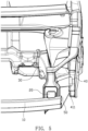
- the front cabin frame assembly further includes a front beam rear section, an outer connection bracket, an inner connection bracket and a middle channel side beam.
- the front beam rear section is connected with the root portion of the front beam front section
- the outer connection bracket is connected with the front beam rear section and the A-pillar
- the inner connection bracket is connected with the front beam rear section and the middle channel side beam.
- the collision energy is absorbed and transferred by a plurality of longitudinal beams and a plurality of lateral beams, which results the head-on collision energy be absorbed effectively and the load transfer path be more reasonable, thereby decreasing the deformation of the passenger compartment and the injury of the passengers, and increasing the collision safety of the entire vehicle.
- the enclosed ring-like front cabin frame includes a plurality of continuously connected overlapping beams along lateral and longitudinal directions, which improves the flexural and torsional stiffness of the vehicle body and further improves the NVH performance.
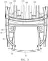
- the bumper beam 10 is disposed in front of the energy absorbing boxes 20, and the energy absorbing boxes 20 are disposed in front of the front beam front sections 30.
- the energy absorbing boxes 20 are disposed at two opposite ends of the bumper beam 10 and threadedly connected with front ends of the front beam front sections 30.
- the front beam front section 30 extends along a length direction (longitudinal direction) of the vehicle body, and the cowl reinforcement crossbeam 80 extends along a width direction (lateral direction) of the vehicle body. Two opposite ends of the cowl reinforcement crossbeam 80 are connected with root portions of the front beam front sections 30 respectively.
- This stable structure is capable of improving collision performance, the flexural and torsional stiffness and the NVH performance of the front cabin.
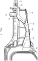
- the upper side beams 40 are disposed at outer sides of the front beam front sections 30 along the width direction of the vehicle body. Front ends of the upper side beams 40 are connected with the front ends of the front beam front sections 30 through the front beam connection brackets 50. Root portions of the upper side beams 40 are connected with the A-pillars 110.
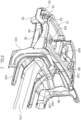
- the upper side beam 40 includes a first portion 41, a second portion 42 and a third portion 43.
- the first portion 41 is connected with the front end of the front beam front section 30, and the third portion 43 is connected with an upper portion of the A-pillar 110.
- a height of the first portion 41 is lower than a height of the third portion 43, this is because under the consideration of layout space requirement such as avoid the headlamp, the smaller the height difference between the first portion 41 and the third portion 43 is, the better the collision performance of the upper beam 40 is, due to the load transfer path along the upper side beam 40 is more straight.
- the second portion 42 connects the first portion 41 with the third portion 43 and is configured in arc shape.
- the arc-shaped configuration of the second portion 42 could avoid tire envelope and extend load absorb and transfer path, so that the upper side beam 40 could absorb and transfer the collision energy more effectively.
- the three portions of the upper side beam 40 could be arranged in different materials, for example, the first portion 41 and the second portion 42 are made of high-strength steel with a lower yield strength, while the third portion 43 is made of high-strength steel with a higher yield strength, thereby making the yield strength of the first portion 41, the second portion 42 and the third portion 43 increases gradually, and further making the entire structure of the upper side beam 40 be soft in front and hard in back, and weak in front and strong in back, so that the front portion of the upper side beam 40 could fully collapse and effectively absorb collision energy, making the rear portion of the upper side beam 40 could dissipate and transfer the rest of the collision energy effectively.
- the obstacle could contact with the upper side beam 40 as it contacts with the front end of the front beam front section 30 in the case that the bumper beam 10 and the energy absorbing box 20 already collapsed and absorbed the collision energy effectively, so that the collision energy could be dissipated and transferred promptly and effectively.
- Due to the height of the front end of the first portion 41 is higher than the height of the front end of the front beam front section 30 along the height direction of the vehicle body, the collision energy could be transferred to the front end of the front beam front section 30 and the upper side beam 40, meanwhile, the height difference of two opposite ends of the upper side beam 40 is decreased, and a perfect energy absorb and transfer effect is obtained.
- a covering plate 411 is disposed at the frontmost of the first portion 41, which prevents the obstacle from invading in an inner compartment of the upper side beam 40 and reducing the energy absorb and transfer effect of the front end of the upper side beam 40.
- a plurality of energy absorbing ribs 421 are disposed at a lower part of a middle portion of the second portion 42 to benefit the first portion 41 and the second portion 42 of the upper side beam 40 to fully collapse and effectively absorb the collision energy, and decrease the impact of the rear portion of the upper side beam 40 (i.e., the third portion 43) on the A-pillar 110.
- a width of the upper side beam 40 substantially equals to a width of the A-pillar 110 along the width direction of the vehicle body, which prevents a curved structure being formed between the upper side beam 40 and the A-pillar 110, and further ensures the collision energy be transferred along a straight line.
- the windshield crossbeam 150 is disposed above the frame of the dash panel with left and right ends thereof connected with the A-pillar 10, and the cowl reinforcement crossbeam 80 is disposed below the frame of the dash panel and connected with the A-pillar 110, thereby forming two continuously connected reinforcement structures along lateral direction.
Landscapes
- Engineering & Computer Science (AREA)
- Mechanical Engineering (AREA)
- Chemical & Material Sciences (AREA)
- Combustion & Propulsion (AREA)
- Transportation (AREA)
- Body Structure For Vehicles (AREA)
Claims (11)
- Eine vordere Kabinenrahmenbaugruppe, dadurch gekennzeichnet, dass sie Folgendes umfasst: einen vorderen Trägerabschnitt (30), einen oberen Seitenträger (40), einen Windlaufverstärkungsquerträger (80), eine äußere Windlaufverstärkung (90) und eine A-Säule (110), wobei der obere Seitenträger (40) an der Außenseite des vorderen Trägerabschnitts (30) entlang einer Breitenrichtung einer Fahrzeugkarosserie angeordnet und ein vorderes Ende des vorderen Trägerabschnitts (30) seitlich mit A verbunden ist. Das vordere Ende des oberen Seitenträgers (40), ein Wurzelabschnitt des vorderen Abschnitts (30) des Vorderträgers, der mit dem Windlaufverstärkungsquerträger (80) verbunden ist, und ein Wurzelabschnitt des oberen Seitenträgers (40), der mit der A-Säule verbunden ist (110), wobei der Windlaufverstärkungsquerträger (80) unterhalb eines Rahmens eines Armaturenbretts angeordnet und mit der A-Säule (110) verbunden ist, wobei der Windschutzscheibenquerträger (150) links und rechts oberhalb des Rahmens des Armaturenbretts angeordnet ist, ist auch seitlich mit A verbunden. Die Enden davon sind mit der A-Säule (110) verbunden, wodurch zwei kontinuierlich verbundene Verstärkungsstrukturen entlang der seitlichen Richtung gebildet werden, wobei die äußere Verstärkung (90) des Windlaufs mit dem Wurzelabschnitt des vorderen Trägerabschnitts (30) und der A-Säule verbunden ist (110).
- Vordere Kabinenrahmenbaugruppe nach Anspruch 1, wobei die vordere Kabinenrahmenbaugruppe, außerdem einen energieabsorbierenden Kasten (20), der vor dem vorderen Abschnitt (30) des Vorderträgers angeordnet ist, und einen darin angeordneten Stoßfänger Träger (10) umfasst. Die Vorderseite des Energieabsorptionskastens (20), der Stoßfänger Träger (10), der Energieabsorptionskasten (20), der vordere Abschnitt des Vorderträgers (30) und der Motorhauben Verstärkungsquerträger (80) bilden zusammenwirkend einen Rahmen mit der Form "□".
- Vordere Kabinenrahmenbaugruppe nach Anspruch 2, wobei sich das vorderste Ende des oberen Seitenträgers (40) über ein hinteres Ende des energieabsorbierenden Kastens (20) hinaus erstreckt.
- Vordere Kabinenrahmenanordnung nach Anspruch 1, wobei der obere Seitenträger (40) einen ersten Abschnitt (41), einen zweiten Abschnitt (42) und einen dritten Abschnitt (43) umfasst, wobei der erste Abschnitt (41) verbunden ist. Mit dem vorderen Trägerabschnitt (30) ist der dritte Abschnitt (43) mit der A-Säule (110) verbunden, der zweite Abschnitt (42) verbindet den ersten Abschnitt (41) mit dem dritten Abschnitt (43) und ist in Bogenform in der Höhe des ersten Abschnitts (41), was geringer als eine Höhe des dritten Abschnitts (43) ist, konfiguriert.
- Vordere Kabinenrahmenbaugruppe nach Anspruch 4, wobei ein vorderes Ende des zweiten Abschnitts (42) mit einem vorderen Ende des vorderen Trägerabschnitts (30) über einen vorderen Scheinwerferquerträger (60) und ein Frontmodul verbunden ist. Bei einer Montagesäule (70) ist ein vorderes Ende des ersten Abschnitts (41) mit dem vorderen Ende des vorderen Abschnitts (30) des vorderen Trägers über eine Verbindungshalterung (50) für den vorderen Träger verbunden, die sich auf der Höhe des vorderen Endes des ersten Abschnitts befindet (41). Das ist etwas höher als die Höhe des vorderen Trägerabschnitts (30), der entlang einer Höhenrichtung einer Fahrzeugkarosserie, verläuft.
- Vordere Kabinenrahmenbaugruppe nach Anspruch 5, wobei die vordere Kabinenrahmenbaugruppe außerdem eine Tropfschiene (160) und einen vorderen Turm (100) umfasst, der zwischen dem vorderen Balkenabschnitt (30) und dem oberen Seitenbalken (40) angeordnet ist, ein oberer Abschnitt des vorderen Turms (100) ist mit zwei gegenüberliegenden Enden der Tropfschiene (160), der Verbindungshalterung (50) des vorderen Balkens, des vorderen Turms (100) und des vorderen Abschnitts (30) des vorderen Balkens verbunden, und der obere Seitenträger (40) bilden zusammen einen Rahmen mit der Form "□".
- Vordere Kabinenrahmenbaugruppe nach Anspruch 4, wobei der vorderste Teil des ersten Abschnitts (41) eine Abdeckplatte (411) aufweist und ein unterer Teil eines mittleren Abschnitts des zweiten Abschnitts (42) mehrere Energieträger, der über eine Vielzahl energieabsorbierender Rippen (421) verfügt.
- Vordere Kabinenrahmenbaugruppe nach Anspruch 4, wobei eine Querfläche des dritten Abschnitts (43) von einem mit dem zweiten Abschnitt (42) verbundenen Ende zu einem mit der A-Säule (110) verbundenen Enden hin allmählich zunimmt. Der dritte Abschnitt (43) und die A-Säule (110) verbinden sich zu einer durchgehend verbundenen Struktur.
- Vordere Kabinenrahmenbaugruppe nach Anspruch 4, wobei die Streckgrenze des ersten Abschnitts (41), des zweiten Abschnitts (42) und des dritten Abschnitts (43) allmählich zunimmt.
- Vordere Kabinenrahmenbaugruppe nach Anspruch 1, wobei die vordere Kabinenrahmenbaugruppe außerdem einen hinteren Abschnitt (120) des vorderen Trägers, eine äußere Verbindungshalterung (130), eine innere Verbindungshalterung (140) und einen mittleren Kanalseitenträger umfasst (180), der hintere Abschnitt (120) des Vorderträgers ist mit dem Wurzelabschnitt des vorderen Abschnitts (30) des Vorderträgers verbunden, die äußere Verbindungshalterung (130) ist mit dem hinteren Abschnitt (120) des Vorderträgers verbunden und der A- Säule (110) ist die innere Verbindungshalterung (140) mit dem hinteren Abschnitt des Vorderträgers (120) und dem Seitenträger des Mittelkanals (180) verbunden.
- Vordere Kabinenrahmenanordnung nach Anspruch 10, wobei die vordere Kabinenrahmenanordnung außerdem einen Mittelkanal (170) und einen Windschutzscheibenquerträger (150) umfasst, der über dem Windlaufverstärkungsquerträger (80) angeordnet ist, wobei der Windschutzscheibenquerträger (150) die A-Säule (110), der Windlaufverstärkungsquerträger (80), die Windlaufaußenverstärkung (90), zusammenwirkend einen Rahmen mit der Form eines mittleren Abschnitts des Windlaufverstärkungsquerträgers (80), der mit dem Mittelkanal (170) verbunden ist, und der mittlere Kanalseitenträger (180), um eine durchgehend verbundene Struktur zu gestalten, bilden.
Applications Claiming Priority (2)
| Application Number | Priority Date | Filing Date | Title |
|---|---|---|---|
| CN201510946358.8A CN106882272A (zh) | 2015-12-16 | 2015-12-16 | 前机舱框架总成 |
| PCT/CN2016/097569 WO2017101513A1 (zh) | 2015-12-16 | 2016-08-31 | 前机舱框架总成 |
Publications (4)
| Publication Number | Publication Date |
|---|---|
| EP3392123A1 EP3392123A1 (de) | 2018-10-24 |
| EP3392123A4 EP3392123A4 (de) | 2019-08-28 |
| EP3392123B1 true EP3392123B1 (de) | 2024-07-03 |
| EP3392123C0 EP3392123C0 (de) | 2024-07-03 |
Family
ID=59055655
Family Applications (1)
| Application Number | Title | Priority Date | Filing Date |
|---|---|---|---|
| EP16874573.5A Active EP3392123B1 (de) | 2015-12-16 | 2016-08-31 | Frontkabinenrahmenanordnung |
Country Status (4)
| Country | Link |
|---|---|
| US (1) | US10543873B2 (de) |
| EP (1) | EP3392123B1 (de) |
| CN (1) | CN106882272A (de) |
| WO (1) | WO2017101513A1 (de) |
Families Citing this family (43)
| Publication number | Priority date | Publication date | Assignee | Title |
|---|---|---|---|---|
| US10661832B2 (en) * | 2016-09-07 | 2020-05-26 | Thunder Power Electric Vehicle Development Company Limited | Angle and geometry of the front cross member |
| KR102371239B1 (ko) * | 2017-04-21 | 2022-03-04 | 현대자동차 주식회사 | 전방 차체 보강구조 |
| KR20180129084A (ko) * | 2017-05-25 | 2018-12-05 | 현대자동차주식회사 | 충돌흡수 구조를 갖는 일체형 사이드 멤버 |
| CN109204544B (zh) | 2017-06-30 | 2020-11-06 | 比亚迪股份有限公司 | 车身结构和车辆 |
| CN109204527B (zh) * | 2017-06-30 | 2021-04-20 | 比亚迪股份有限公司 | 车身结构和车辆 |
| CN109204520B (zh) * | 2017-06-30 | 2021-06-18 | 比亚迪股份有限公司 | 车身结构和车辆 |
| CN109204497B (zh) * | 2017-06-30 | 2021-01-01 | 比亚迪股份有限公司 | 车身结构和车辆 |
| CN108016506B (zh) * | 2017-11-09 | 2020-02-21 | 广州汽车集团股份有限公司 | 车辆机舱总成 |
| CN107963130B (zh) * | 2017-11-22 | 2019-08-13 | 威马智慧出行科技(上海)有限公司 | 前围总成及包括其的汽车 |
| CN108001533A (zh) * | 2017-11-22 | 2018-05-08 | 奇瑞汽车股份有限公司 | 前舱车架 |
| JP7035848B2 (ja) * | 2018-06-27 | 2022-03-15 | トヨタ自動車株式会社 | 車両の下部車体構造 |
| CN109823410B (zh) * | 2019-02-28 | 2024-04-19 | 东风小康汽车有限公司重庆分公司 | 一种前机舱封板连接结构 |
| CN109910802B (zh) * | 2019-03-06 | 2021-05-25 | 宁波吉利汽车研究开发有限公司 | 一种新型的小偏置结构 |
| WO2020217085A1 (en) * | 2019-04-23 | 2020-10-29 | Arcelormittal | Tunnel having integrated lateral reinforcements |
| CN111619670B (zh) * | 2019-09-19 | 2021-07-13 | 长城汽车股份有限公司 | 前车身结构及汽车 |
| CN112572614B (zh) * | 2019-09-30 | 2022-06-21 | 广州汽车集团股份有限公司 | 车辆的梁结构组件以及具有该梁结构组件的车辆 |
| CN112572618A (zh) * | 2019-09-30 | 2021-03-30 | 比亚迪股份有限公司 | 车辆前舱结构和车辆 |
| CN113002633A (zh) * | 2019-12-19 | 2021-06-22 | 观致汽车有限公司 | 前机舱骨架组件 |
| CN113044117A (zh) * | 2019-12-26 | 2021-06-29 | 观致汽车有限公司 | 车辆前机舱的上纵梁总成和具有其的车辆 |
| CN111152847B (zh) * | 2020-01-08 | 2021-06-01 | 上海龙创汽车设计股份有限公司 | 一种汽车骨架加强结构 |
| CN113365906A (zh) * | 2020-08-31 | 2021-09-07 | 华为技术有限公司 | 一种车辆的前部结构以及车辆 |
| CN112622795B (zh) * | 2020-12-28 | 2021-08-24 | 湖南大学 | 一种抵抗正碰的车辆结构及制造方法 |
| CN116529147A (zh) * | 2021-01-22 | 2023-08-01 | 浙江吉利控股集团有限公司 | 一种立柱结构、车身结构及车辆 |
| CN114954663A (zh) * | 2021-02-19 | 2022-08-30 | 威马智慧出行科技(上海)股份有限公司 | 一种针对车辆小重叠碰撞的防护结构及车辆 |
| JP7604985B2 (ja) * | 2021-03-29 | 2024-12-24 | マツダ株式会社 | 車体構造 |
| CN113147908A (zh) * | 2021-04-20 | 2021-07-23 | 重庆长安汽车股份有限公司 | 一种车身前端结构 |
| CN114932953B (zh) * | 2021-06-29 | 2023-05-05 | 比亚迪股份有限公司 | 车身框架和具有其的车辆 |
| CN113460166B (zh) * | 2021-06-30 | 2022-04-01 | 东风汽车集团股份有限公司 | 一种模块化偏置碰加强结构 |
| CN113443010B (zh) * | 2021-07-06 | 2022-09-09 | 合肥长安汽车有限公司 | 汽车机舱后横梁总成 |
| CN113771954B (zh) * | 2021-08-31 | 2023-09-22 | 重庆长安汽车股份有限公司 | 一种纯电动汽车机舱防侵入结构 |
| JP7553414B2 (ja) * | 2021-09-09 | 2024-09-18 | トヨタ自動車株式会社 | 車両 |
| CN113968285B (zh) * | 2021-10-26 | 2023-01-10 | 东风越野车有限公司 | 一种越野车车身前机舱结构 |
| CN116252864A (zh) * | 2021-12-09 | 2023-06-13 | 广州汽车集团股份有限公司 | 一种汽车机舱框架结构、汽车 |
| JP7485708B2 (ja) | 2022-03-10 | 2024-05-16 | 本田技研工業株式会社 | 車両下部構造 |
| CN115158479B (zh) * | 2022-06-29 | 2023-09-22 | 重庆长安汽车股份有限公司 | 一种基于平台架构的车身前机舱一体式结构及汽车 |
| CN115402415B (zh) * | 2022-07-20 | 2024-04-16 | 岚图汽车科技有限公司 | 一种前机舱以及车辆 |
| CN116252863B (zh) * | 2023-01-19 | 2025-05-27 | 东风汽车集团股份有限公司 | 一种前机舱骨架及车辆 |
| CN118850189B (zh) * | 2023-04-28 | 2025-11-18 | 长城汽车股份有限公司 | 车身前部框架和车辆 |
| CN116691843B (zh) * | 2023-05-29 | 2025-09-09 | 重庆长安汽车股份有限公司 | 一种前端车架结构及汽车 |
| CN116654107B (zh) * | 2023-06-26 | 2026-02-27 | 浙江吉利控股集团有限公司 | 用于车辆的车身前纵梁总成、前端框架总成及车辆 |
| CN117002626A (zh) * | 2023-08-25 | 2023-11-07 | 奇瑞汽车股份有限公司 | 一种混动汽车发动机舱后部总成 |
| CN119611521B (zh) * | 2023-09-13 | 2025-11-04 | 比亚迪股份有限公司 | 车身框架结构和车辆 |
| CN117601970B (zh) * | 2023-12-20 | 2026-01-27 | 蔚来汽车科技(安徽)有限公司 | 车辆的前纵梁后段件及车辆 |
Family Cites Families (21)
| Publication number | Priority date | Publication date | Assignee | Title |
|---|---|---|---|---|
| JPH07228267A (ja) * | 1994-02-17 | 1995-08-29 | Mitsubishi Motors Corp | 車体の強度部材構造 |
| JP2004106704A (ja) * | 2002-09-18 | 2004-04-08 | Fuji Heavy Ind Ltd | 自動車の車体前部構造 |
| JP4144385B2 (ja) * | 2003-03-12 | 2008-09-03 | 三菱自動車工業株式会社 | 自動車の車室前部の結合構造 |
| JP4304537B2 (ja) * | 2007-02-23 | 2009-07-29 | トヨタ自動車株式会社 | 車両骨格構造 |
| JP5029328B2 (ja) * | 2007-12-05 | 2012-09-19 | マツダ株式会社 | 自動車の前部車体構造 |
| DE102009056840A1 (de) * | 2009-12-03 | 2011-06-09 | GM Global Technology Operations LLC, ( n. d. Ges. d. Staates Delaware ), Detroit | Unterbaustruktur einer Kraftfahrzeugkarosserie |
| CN102358349B (zh) | 2011-08-11 | 2013-06-12 | 奇瑞汽车股份有限公司 | 一种汽车车身前部骨架结构 |
| US20150061320A1 (en) * | 2012-01-10 | 2015-03-05 | Honday Motor Co., Ltd. | Vehicle body frame structure of motor vehicle |
| US8770653B2 (en) * | 2012-04-16 | 2014-07-08 | Ford Global Technologies, Llc | Bodywork arrangement for a front end and a passenger compartment of a vehicle |
| KR101448747B1 (ko) * | 2012-10-02 | 2014-10-08 | 현대자동차 주식회사 | 전방 차체 구조 |
| CN202987288U (zh) * | 2012-12-07 | 2013-06-12 | 北京汽车股份有限公司 | 前指梁总成、发动机舱及汽车 |
| DE102014204516B4 (de) * | 2013-03-26 | 2023-06-22 | Subaru Corporation | Fahrzeugkarosseriestruktur |
| CN103770841B (zh) * | 2013-05-27 | 2015-05-27 | 广州汽车集团股份有限公司 | 一种汽车车身骨架结构 |
| CN203306103U (zh) * | 2013-05-30 | 2013-11-27 | 长城汽车股份有限公司 | 多通道传力机构及设有该机构的前机舱和车辆 |
| CN203358689U (zh) * | 2013-05-31 | 2013-12-25 | 奇瑞汽车股份有限公司 | 一种车身碰撞吸能结构 |
| CN203637949U (zh) * | 2013-12-02 | 2014-06-11 | 奇瑞汽车股份有限公司 | 一种汽车前挡板总成 |
| CN204415518U (zh) * | 2015-01-05 | 2015-06-24 | 广州汽车集团股份有限公司 | 前舱纵梁后段结构与汽车 |
| CN204623579U (zh) * | 2015-04-27 | 2015-09-09 | 北京汽车股份有限公司 | 汽车前围结构及汽车 |
| CN204775483U (zh) * | 2015-05-29 | 2015-11-18 | 广州汽车集团股份有限公司 | 一种汽车机舱总成 |
| CN204821716U (zh) * | 2015-05-29 | 2015-12-02 | 广州汽车集团股份有限公司 | 一种汽车机舱总成 |
| CN205273623U (zh) * | 2015-12-16 | 2016-06-01 | 广州汽车集团股份有限公司 | 前机舱框架总成 |
-
2015
- 2015-12-16 CN CN201510946358.8A patent/CN106882272A/zh active Pending
-
2016
- 2016-08-31 EP EP16874573.5A patent/EP3392123B1/de active Active
- 2016-08-31 US US15/744,731 patent/US10543873B2/en active Active
- 2016-08-31 WO PCT/CN2016/097569 patent/WO2017101513A1/zh not_active Ceased
Also Published As
| Publication number | Publication date |
|---|---|
| EP3392123A4 (de) | 2019-08-28 |
| CN106882272A (zh) | 2017-06-23 |
| US20180201326A1 (en) | 2018-07-19 |
| EP3392123A1 (de) | 2018-10-24 |
| US10543873B2 (en) | 2020-01-28 |
| WO2017101513A1 (zh) | 2017-06-22 |
| EP3392123C0 (de) | 2024-07-03 |
Similar Documents
| Publication | Publication Date | Title |
|---|---|---|
| EP3392123B1 (de) | Frontkabinenrahmenanordnung | |
| JP6372494B2 (ja) | 車両の前部車体構造 | |
| JP6432535B2 (ja) | 車両の前部車体構造 | |
| US9371093B1 (en) | Vehicles having upper side member reinforcement portions | |
| US7810878B2 (en) | Vehicle body structure | |
| JP4286884B2 (ja) | 自動車の車体構造 | |
| US7766420B2 (en) | Front structure of vehicle body | |
| KR102383247B1 (ko) | 전방 차체 보강구조 | |
| CN205273623U (zh) | 前机舱框架总成 | |
| US20180154943A1 (en) | Vehicle engine compartment assembly | |
| KR102440606B1 (ko) | 전방 차체 보강구조 | |
| CN107074296B (zh) | 用于轿车的前厢的支撑装置和轿车 | |
| CN110040186A (zh) | 下部车身结构 | |
| US9266567B1 (en) | Vehicles having a dash panel reinforcement gusset | |
| US9238487B1 (en) | Inner front side member to rocker support reinforcement gussets for vehicle front structures | |
| JP6248959B2 (ja) | 車両骨格構造 | |
| JP6252160B2 (ja) | キャブオーバー型車両の構造 | |
| KR100844712B1 (ko) | 차량의 카울 사이드부 보강구조 | |
| JP6303479B2 (ja) | キャブオーバー型車両の構造 | |
| CN214689769U (zh) | 一种前端结构和车辆 | |
| JP2005231436A (ja) | 自動車の前部車体構造 | |
| CN114056433B (zh) | 车辆的下部车身结构 | |
| EP4108554A1 (de) | Frontlenker-lkw | |
| CN100519310C (zh) | 一种可伸缩顶汽车前底板的布置结构 | |
| KR20240104916A (ko) | 차량의 사이드실 어셈블리 |
Legal Events
| Date | Code | Title | Description |
|---|---|---|---|
| STAA | Information on the status of an ep patent application or granted ep patent |
Free format text: STATUS: THE INTERNATIONAL PUBLICATION HAS BEEN MADE |
|
| PUAI | Public reference made under article 153(3) epc to a published international application that has entered the european phase |
Free format text: ORIGINAL CODE: 0009012 |
|
| STAA | Information on the status of an ep patent application or granted ep patent |
Free format text: STATUS: REQUEST FOR EXAMINATION WAS MADE |
|
| 17P | Request for examination filed |
Effective date: 20180116 |
|
| AK | Designated contracting states |
Kind code of ref document: A1 Designated state(s): AL AT BE BG CH CY CZ DE DK EE ES FI FR GB GR HR HU IE IS IT LI LT LU LV MC MK MT NL NO PL PT RO RS SE SI SK SM TR |
|
| AX | Request for extension of the european patent |
Extension state: BA ME |
|
| RIN1 | Information on inventor provided before grant (corrected) |
Inventor name: YE, BAOWEN Inventor name: GENG, FURONG Inventor name: WU, CHUNFU Inventor name: YANG, JINXIU Inventor name: CHEN, DONG Inventor name: YUAN, HUANQUAN |
|
| DAV | Request for validation of the european patent (deleted) | ||
| DAX | Request for extension of the european patent (deleted) | ||
| A4 | Supplementary search report drawn up and despatched |
Effective date: 20190731 |
|
| RIC1 | Information provided on ipc code assigned before grant |
Ipc: B62D 25/08 20060101AFI20190725BHEP Ipc: B60R 19/34 20060101ALI20190725BHEP Ipc: B62D 21/15 20060101ALI20190725BHEP Ipc: B62D 25/20 20060101ALI20190725BHEP |
|
| STAA | Information on the status of an ep patent application or granted ep patent |
Free format text: STATUS: EXAMINATION IS IN PROGRESS |
|
| 17Q | First examination report despatched |
Effective date: 20201216 |
|
| GRAP | Despatch of communication of intention to grant a patent |
Free format text: ORIGINAL CODE: EPIDOSNIGR1 |
|
| STAA | Information on the status of an ep patent application or granted ep patent |
Free format text: STATUS: GRANT OF PATENT IS INTENDED |
|
| INTG | Intention to grant announced |
Effective date: 20240416 |
|
| GRAS | Grant fee paid |
Free format text: ORIGINAL CODE: EPIDOSNIGR3 |
|
| GRAA | (expected) grant |
Free format text: ORIGINAL CODE: 0009210 |
|
| STAA | Information on the status of an ep patent application or granted ep patent |
Free format text: STATUS: THE PATENT HAS BEEN GRANTED |
|
| AK | Designated contracting states |
Kind code of ref document: B1 Designated state(s): AL AT BE BG CH CY CZ DE DK EE ES FI FR GB GR HR HU IE IS IT LI LT LU LV MC MK MT NL NO PL PT RO RS SE SI SK SM TR |
|
| REG | Reference to a national code |
Ref country code: CH Ref legal event code: EP |
|
| REG | Reference to a national code |
Ref country code: DE Ref legal event code: R096 Ref document number: 602016088266 Country of ref document: DE |
|
| U01 | Request for unitary effect filed |
Effective date: 20240703 |
|
| U07 | Unitary effect registered |
Designated state(s): AT BE BG DE DK EE FI FR IT LT LU LV MT NL PT SE SI Effective date: 20240711 |
|
| U20 | Renewal fee for the european patent with unitary effect paid |
Year of fee payment: 9 Effective date: 20240925 |
|
| PG25 | Lapsed in a contracting state [announced via postgrant information from national office to epo] |
Ref country code: NO Free format text: LAPSE BECAUSE OF FAILURE TO SUBMIT A TRANSLATION OF THE DESCRIPTION OR TO PAY THE FEE WITHIN THE PRESCRIBED TIME-LIMIT Effective date: 20241003 |
|
| PG25 | Lapsed in a contracting state [announced via postgrant information from national office to epo] |
Ref country code: GR Free format text: LAPSE BECAUSE OF FAILURE TO SUBMIT A TRANSLATION OF THE DESCRIPTION OR TO PAY THE FEE WITHIN THE PRESCRIBED TIME-LIMIT Effective date: 20241004 Ref country code: PL Free format text: LAPSE BECAUSE OF FAILURE TO SUBMIT A TRANSLATION OF THE DESCRIPTION OR TO PAY THE FEE WITHIN THE PRESCRIBED TIME-LIMIT Effective date: 20240703 |
|
| PG25 | Lapsed in a contracting state [announced via postgrant information from national office to epo] |
Ref country code: IS Free format text: LAPSE BECAUSE OF FAILURE TO SUBMIT A TRANSLATION OF THE DESCRIPTION OR TO PAY THE FEE WITHIN THE PRESCRIBED TIME-LIMIT Effective date: 20241103 |
|
| PG25 | Lapsed in a contracting state [announced via postgrant information from national office to epo] |
Ref country code: CZ Free format text: LAPSE BECAUSE OF FAILURE TO SUBMIT A TRANSLATION OF THE DESCRIPTION OR TO PAY THE FEE WITHIN THE PRESCRIBED TIME-LIMIT Effective date: 20240703 Ref country code: HR Free format text: LAPSE BECAUSE OF FAILURE TO SUBMIT A TRANSLATION OF THE DESCRIPTION OR TO PAY THE FEE WITHIN THE PRESCRIBED TIME-LIMIT Effective date: 20240703 |
|
| PG25 | Lapsed in a contracting state [announced via postgrant information from national office to epo] |
Ref country code: RS Free format text: LAPSE BECAUSE OF FAILURE TO SUBMIT A TRANSLATION OF THE DESCRIPTION OR TO PAY THE FEE WITHIN THE PRESCRIBED TIME-LIMIT Effective date: 20241003 Ref country code: ES Free format text: LAPSE BECAUSE OF FAILURE TO SUBMIT A TRANSLATION OF THE DESCRIPTION OR TO PAY THE FEE WITHIN THE PRESCRIBED TIME-LIMIT Effective date: 20240703 |
|
| PG25 | Lapsed in a contracting state [announced via postgrant information from national office to epo] |
Ref country code: RS Free format text: LAPSE BECAUSE OF FAILURE TO SUBMIT A TRANSLATION OF THE DESCRIPTION OR TO PAY THE FEE WITHIN THE PRESCRIBED TIME-LIMIT Effective date: 20241003 Ref country code: PL Free format text: LAPSE BECAUSE OF FAILURE TO SUBMIT A TRANSLATION OF THE DESCRIPTION OR TO PAY THE FEE WITHIN THE PRESCRIBED TIME-LIMIT Effective date: 20240703 Ref country code: NO Free format text: LAPSE BECAUSE OF FAILURE TO SUBMIT A TRANSLATION OF THE DESCRIPTION OR TO PAY THE FEE WITHIN THE PRESCRIBED TIME-LIMIT Effective date: 20241003 Ref country code: IS Free format text: LAPSE BECAUSE OF FAILURE TO SUBMIT A TRANSLATION OF THE DESCRIPTION OR TO PAY THE FEE WITHIN THE PRESCRIBED TIME-LIMIT Effective date: 20241103 Ref country code: HR Free format text: LAPSE BECAUSE OF FAILURE TO SUBMIT A TRANSLATION OF THE DESCRIPTION OR TO PAY THE FEE WITHIN THE PRESCRIBED TIME-LIMIT Effective date: 20240703 Ref country code: GR Free format text: LAPSE BECAUSE OF FAILURE TO SUBMIT A TRANSLATION OF THE DESCRIPTION OR TO PAY THE FEE WITHIN THE PRESCRIBED TIME-LIMIT Effective date: 20241004 Ref country code: ES Free format text: LAPSE BECAUSE OF FAILURE TO SUBMIT A TRANSLATION OF THE DESCRIPTION OR TO PAY THE FEE WITHIN THE PRESCRIBED TIME-LIMIT Effective date: 20240703 Ref country code: CZ Free format text: LAPSE BECAUSE OF FAILURE TO SUBMIT A TRANSLATION OF THE DESCRIPTION OR TO PAY THE FEE WITHIN THE PRESCRIBED TIME-LIMIT Effective date: 20240703 |
|
| REG | Reference to a national code |
Ref country code: CH Ref legal event code: PL |
|
| PG25 | Lapsed in a contracting state [announced via postgrant information from national office to epo] |
Ref country code: SM Free format text: LAPSE BECAUSE OF FAILURE TO SUBMIT A TRANSLATION OF THE DESCRIPTION OR TO PAY THE FEE WITHIN THE PRESCRIBED TIME-LIMIT Effective date: 20240703 |
|
| PG25 | Lapsed in a contracting state [announced via postgrant information from national office to epo] |
Ref country code: MC Free format text: LAPSE BECAUSE OF FAILURE TO SUBMIT A TRANSLATION OF THE DESCRIPTION OR TO PAY THE FEE WITHIN THE PRESCRIBED TIME-LIMIT Effective date: 20240703 Ref country code: CH Free format text: LAPSE BECAUSE OF NON-PAYMENT OF DUE FEES Effective date: 20240831 |
|
| PG25 | Lapsed in a contracting state [announced via postgrant information from national office to epo] |
Ref country code: SK Free format text: LAPSE BECAUSE OF FAILURE TO SUBMIT A TRANSLATION OF THE DESCRIPTION OR TO PAY THE FEE WITHIN THE PRESCRIBED TIME-LIMIT Effective date: 20240703 |
|
| PLBE | No opposition filed within time limit |
Free format text: ORIGINAL CODE: 0009261 |
|
| STAA | Information on the status of an ep patent application or granted ep patent |
Free format text: STATUS: NO OPPOSITION FILED WITHIN TIME LIMIT |
|
| 26N | No opposition filed |
Effective date: 20250404 |
|
| GBPC | Gb: european patent ceased through non-payment of renewal fee |
Effective date: 20241003 |
|
| PG25 | Lapsed in a contracting state [announced via postgrant information from national office to epo] |
Ref country code: GB Free format text: LAPSE BECAUSE OF NON-PAYMENT OF DUE FEES Effective date: 20241003 |
|
| PG25 | Lapsed in a contracting state [announced via postgrant information from national office to epo] |
Ref country code: IE Free format text: LAPSE BECAUSE OF NON-PAYMENT OF DUE FEES Effective date: 20240831 |
|
| U1N | Appointed representative for the unitary patent procedure changed after the registration of the unitary effect |
Representative=s name: METIDA; LT |
|
| U20 | Renewal fee for the european patent with unitary effect paid |
Year of fee payment: 10 Effective date: 20250826 |
|
| PG25 | Lapsed in a contracting state [announced via postgrant information from national office to epo] |
Ref country code: RO Free format text: LAPSE BECAUSE OF FAILURE TO SUBMIT A TRANSLATION OF THE DESCRIPTION OR TO PAY THE FEE WITHIN THE PRESCRIBED TIME-LIMIT Effective date: 20240703 |
|
| PG25 | Lapsed in a contracting state [announced via postgrant information from national office to epo] |
Ref country code: CY Free format text: LAPSE BECAUSE OF FAILURE TO SUBMIT A TRANSLATION OF THE DESCRIPTION OR TO PAY THE FEE WITHIN THE PRESCRIBED TIME-LIMIT; INVALID AB INITIO Effective date: 20160831 |
|
| PG25 | Lapsed in a contracting state [announced via postgrant information from national office to epo] |
Ref country code: HU Free format text: LAPSE BECAUSE OF FAILURE TO SUBMIT A TRANSLATION OF THE DESCRIPTION OR TO PAY THE FEE WITHIN THE PRESCRIBED TIME-LIMIT; INVALID AB INITIO Effective date: 20160831 |