EP3382205B1 - Verdichter - Google Patents
Verdichter Download PDFInfo
- Publication number
- EP3382205B1 EP3382205B1 EP17760066.5A EP17760066A EP3382205B1 EP 3382205 B1 EP3382205 B1 EP 3382205B1 EP 17760066 A EP17760066 A EP 17760066A EP 3382205 B1 EP3382205 B1 EP 3382205B1
- Authority
- EP
- European Patent Office
- Prior art keywords
- discharge
- refrigerant
- pipe
- discharge port
- housing
- Prior art date
- Legal status (The legal status is an assumption and is not a legal conclusion. Google has not performed a legal analysis and makes no representation as to the accuracy of the status listed.)
- Active
Links
Images


Classifications
-
- F—MECHANICAL ENGINEERING; LIGHTING; HEATING; WEAPONS; BLASTING
- F04—POSITIVE - DISPLACEMENT MACHINES FOR LIQUIDS; PUMPS FOR LIQUIDS OR ELASTIC FLUIDS
- F04C—ROTARY-PISTON, OR OSCILLATING-PISTON, POSITIVE-DISPLACEMENT MACHINES FOR LIQUIDS; ROTARY-PISTON, OR OSCILLATING-PISTON, POSITIVE-DISPLACEMENT PUMPS
- F04C18/00—Rotary-piston pumps specially adapted for elastic fluids
- F04C18/02—Rotary-piston pumps specially adapted for elastic fluids of arcuate-engagement type, i.e. with circular translatory movement of co-operating members, each member having the same number of teeth or tooth-equivalents
-
- F—MECHANICAL ENGINEERING; LIGHTING; HEATING; WEAPONS; BLASTING
- F04—POSITIVE - DISPLACEMENT MACHINES FOR LIQUIDS; PUMPS FOR LIQUIDS OR ELASTIC FLUIDS
- F04C—ROTARY-PISTON, OR OSCILLATING-PISTON, POSITIVE-DISPLACEMENT MACHINES FOR LIQUIDS; ROTARY-PISTON, OR OSCILLATING-PISTON, POSITIVE-DISPLACEMENT PUMPS
- F04C23/00—Combinations of two or more pumps, each being of rotary-piston or oscillating-piston type, specially adapted for elastic fluids; Pumping installations specially adapted for elastic fluids; Multi-stage pumps specially adapted for elastic fluids
- F04C23/008—Hermetic pumps
-
- F—MECHANICAL ENGINEERING; LIGHTING; HEATING; WEAPONS; BLASTING
- F04—POSITIVE - DISPLACEMENT MACHINES FOR LIQUIDS; PUMPS FOR LIQUIDS OR ELASTIC FLUIDS
- F04C—ROTARY-PISTON, OR OSCILLATING-PISTON, POSITIVE-DISPLACEMENT MACHINES FOR LIQUIDS; ROTARY-PISTON, OR OSCILLATING-PISTON, POSITIVE-DISPLACEMENT PUMPS
- F04C18/00—Rotary-piston pumps specially adapted for elastic fluids
- F04C18/02—Rotary-piston pumps specially adapted for elastic fluids of arcuate-engagement type, i.e. with circular translatory movement of co-operating members, each member having the same number of teeth or tooth-equivalents
- F04C18/0207—Rotary-piston pumps specially adapted for elastic fluids of arcuate-engagement type, i.e. with circular translatory movement of co-operating members, each member having the same number of teeth or tooth-equivalents both members having co-operating elements in spiral form
- F04C18/0215—Rotary-piston pumps specially adapted for elastic fluids of arcuate-engagement type, i.e. with circular translatory movement of co-operating members, each member having the same number of teeth or tooth-equivalents both members having co-operating elements in spiral form where only one member is moving
-
- F—MECHANICAL ENGINEERING; LIGHTING; HEATING; WEAPONS; BLASTING
- F04—POSITIVE - DISPLACEMENT MACHINES FOR LIQUIDS; PUMPS FOR LIQUIDS OR ELASTIC FLUIDS
- F04C—ROTARY-PISTON, OR OSCILLATING-PISTON, POSITIVE-DISPLACEMENT MACHINES FOR LIQUIDS; ROTARY-PISTON, OR OSCILLATING-PISTON, POSITIVE-DISPLACEMENT PUMPS
- F04C29/00—Component parts, details or accessories of pumps or pumping installations, not provided for in groups F04C18/00 - F04C28/00
- F04C29/04—Heating; Cooling; Heat insulation
- F04C29/042—Heating; Cooling; Heat insulation by injecting a fluid
-
- F—MECHANICAL ENGINEERING; LIGHTING; HEATING; WEAPONS; BLASTING
- F04—POSITIVE - DISPLACEMENT MACHINES FOR LIQUIDS; PUMPS FOR LIQUIDS OR ELASTIC FLUIDS
- F04C—ROTARY-PISTON, OR OSCILLATING-PISTON, POSITIVE-DISPLACEMENT MACHINES FOR LIQUIDS; ROTARY-PISTON, OR OSCILLATING-PISTON, POSITIVE-DISPLACEMENT PUMPS
- F04C29/00—Component parts, details or accessories of pumps or pumping installations, not provided for in groups F04C18/00 - F04C28/00
- F04C29/12—Arrangements for admission or discharge of the working fluid, e.g. constructional features of the inlet or outlet
- F04C29/124—Arrangements for admission or discharge of the working fluid, e.g. constructional features of the inlet or outlet with inlet and outlet valves specially adapted for rotary or oscillating piston pumps
- F04C29/126—Arrangements for admission or discharge of the working fluid, e.g. constructional features of the inlet or outlet with inlet and outlet valves specially adapted for rotary or oscillating piston pumps of the non-return type
- F04C29/128—Arrangements for admission or discharge of the working fluid, e.g. constructional features of the inlet or outlet with inlet and outlet valves specially adapted for rotary or oscillating piston pumps of the non-return type of the elastic type, e.g. reed valves
-
- F—MECHANICAL ENGINEERING; LIGHTING; HEATING; WEAPONS; BLASTING
- F04—POSITIVE - DISPLACEMENT MACHINES FOR LIQUIDS; PUMPS FOR LIQUIDS OR ELASTIC FLUIDS
- F04C—ROTARY-PISTON, OR OSCILLATING-PISTON, POSITIVE-DISPLACEMENT MACHINES FOR LIQUIDS; ROTARY-PISTON, OR OSCILLATING-PISTON, POSITIVE-DISPLACEMENT PUMPS
- F04C2240/00—Components
- F04C2240/80—Other components
- F04C2240/806—Pipes for fluids; Fittings therefor
Definitions
- the present invention relates to a compressor.
- a hermetic scroll compressor is used for a refrigerator or an air conditioner so as to compress and discharge an externally supplied refrigerant.
- a discharge chamber is formed in an upper portion of a scroll-type compression mechanism in a hermetic housing.
- the discharge chamber is a space surrounded by the scroll-type compression mechanism and the housing.
- a refrigerant compressed by the compression mechanism is supplied to the discharge chamber so as to temporarily store the refrigerant. Thereafter, the refrigerant is discharged outward from a discharge pipe.
- PTLS 1 and 2 below disclose a scroll-type compressor which has an injection pipe for introducing an intermediate-pressure refrigerant from the outside into the compression chamber of the compression mechanism.
- a liquid refrigerant is supplied to the compression chamber via the injection pipe. In this manner, a temperature of the refrigerant is lowered by latent heat generated when the liquid refrigerant evaporates, thereby cooling the inside of the compression chamber.
- the scroll-type compressor may have a capacity control pipe (hereinafter, referred to as a bypass pipe) for externally extracting the intermediate-pressure refrigerant of the compression chamber.
- the externally extracted intermediate-pressure refrigerant returns to a suction side of the compressor. In this manner, it is possible to perform a capacity control operation of the compressor.
- the injection pipe or the bypass pipe disposed in the hermetic scroll compressor penetrates an upper portion of the housing and the discharge chamber, and is connected to the compression mechanism. Therefore, the refrigerant passing through the injection pipe or the bypass pipe is heated by a high-temperature refrigerant inside the discharge chamber.
- the injection pipe or the bypass pipe is installed so that the refrigerant discharged from a discharge port 29 is caused to flow toward an injection pipe 50 or the bypass pipe by a reed valve 40, the refrigerant passing through the injection pipe 50 or the bypass pipe is likely to be heated. If the refrigerant passing through the injection pipe is heated, there is a problem in that the inside of the compression chamber cannot be cooled. If the refrigerant passing through the bypass pipe is heated, there is a problem in that a volume of the refrigerant increases and compression efficiency is lowered. In any case, desired performance of the compressor cannot be obtained.
- the present invention is made in view of these circumstances, and an object thereof is to provide a compressor which is installed inside a discharge chamber, and which is capable of suppressing a temperature rise of a refrigerant passing through a pipe unit such as an injection pipe or a bypass pipe.
- a compressor according to the present invention is defined by claim 1 or claim 2.
- a compressor includes a housing, a scroll-type compression mechanism accommodated in the housing, a discharge cover or a fixed scroll of the compression mechanism having a discharge port through which a refrigerant compressed by the compression mechanism passes, a discharge chamber formed between the housing and the discharge cover or the fixed scroll, a pipe unit disposed so as to internally pass through the discharge chamber, and internally circulating the refrigerant, and a reed valve disposed in the discharge port of the discharge cover or the fixed scroll, and having a configuration in which the refrigerant discharged from the discharge port to the discharge chamber is blown in a direction away from the pipe unit.
- the refrigerant compressed by the compression mechanism is discharged from the discharge port disposed in the discharge cover or the fixed scroll of the compression mechanism, to the discharge chamber formed between the housing and the discharge cover or between the housing and the fixed scroll of the compression mechanism.
- the refrigerant discharged from the discharge port to the discharge chamber is blown in the direction away from the pipe unit by the reed valve disposed in the discharge port. Therefore, the high-temperature refrigerant discharged from the discharge port does not directly flow to the pipe unit at the shortest distance. Accordingly, the refrigerant passing through the pipe unit is less likely to be heated.
- the reed valve has a plate-shaped member which blows the refrigerant discharged from the discharge port, in a predetermined blowing direction, and the pipe unit is disposed on a rear side in the blowing direction.
- the refrigerant discharged from the discharge port is blown in the predetermined blowing direction by the plate-shaped member of the reed valve. Then, the pipe unit is disposed on the rear side in the predetermined blowing direction of the refrigerant. Therefore, the refrigerant discharged from the discharge port to the discharge chamber does not directly flow to the pipe unit. Accordingly, the refrigerant passing through the pipe unit is less likely to be heated.
- the plate-shaped member of the reed valve is long in one direction, and has one end side fixed to the discharge cover or the fixed scroll, and the other end side capable of opening and closing the discharge port.
- a line connecting one end and the other end of the plate-shaped member and a line connecting the discharge port and the pipe unit forms an angle of 90° or smaller.
- the plate-shaped member of the reed valve is long in one direction, and has one end side fixed to the discharge cover or the fixed scroll, and the other end side capable of opening and closing the discharge port. According to the invention, when the discharge ports are respectively disposed at two locations and the reed valves are disposed one by one for each of the discharge ports, the plate-shaped members of the two reed valves are installed so as to interpose the pipe unit therebetween.
- the pipe unit may be installed on a perpendicular bisector of a line segment connecting the two discharge ports.
- an angle formed between a line connecting one end and the other end of one of the plate-shaped members and a line connecting one end and the other end of the other one of the plate-shaped members may be 90° or smaller.
- the compressor includes a discharge pipe installed so as to penetrate the housing, and discharging the refrigerant inside the discharge chamber outward of the discharge chamber.
- the discharge pipe is installed so that the refrigerant discharged from the discharge port to the discharge chamber is blown in a direction closer to the discharge pipe by the reed valve.
- the compressor may further include a discharge pipe installed so as to penetrate the housing, and discharging the refrigerant inside the discharge chamber outward of the discharge chamber.
- the discharge pipe may be installed so that the refrigerant discharged from the discharge ports to the discharge chamber is blown in a direction closer to the discharge pipe by the reed valves.
- the discharge pipe may be installed on a side opposite to the pipe unit across the line connecting the two discharge ports.
- the present invention it is possible to suppress a temperature rise of the refrigerant passing through the pipe unit such as the injection pipe or the bypass pipe installed inside the discharge chamber.
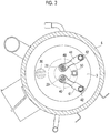
- a hermetic scroll compressor 1 serving as a scroll fluid machine has a cylindrical hermetic housing 2 whose bottom portion is brought into a hermetic state by a lower cover and which is long in an upward-downward direction. An upper portion of the hermetic housing 2 is brought into a hermetic state by a discharge cover 3 and an upper cover 4. A discharge chamber 5 to which compressed high-pressure gas is discharged is formed between the discharge cover 3 and the upper cover 4.
- an upper bearing member (frame member) 6 is fixedly installed in the upper portion.
- a scroll compression mechanism 7 is incorporated in the hermetic housing 2 via the upper bearing member 6, and an electric motor 10 having a stator 8 and a rotor 9 is installed in the lower portion.
- the electric motor 10 is incorporated by fixedly installing the stator 8 in the hermetic housing 2, and a crankshaft 11 is fixed to the rotor 9.
- a crank pin 12 whose axis is eccentric by a predetermined dimension is disposed in an upper end of the crankshaft 11.
- the crank pin 12 is connected to the scroll compression mechanism 7, thereby enabling the scroll compression mechanism 7 to be driven by the electric motor 10.
- an upper portion of the crankshaft 11 is rotatably supported by a journal bearing portion 6A of the upper bearing member 6, and a lower end portion is rotatably supported by a lower journal bearing 13 disposed in the lower portion of the hermetic housing 2.
- a displacement-type oil supply pump 14 is disposed between the lower journal bearing 13 and the lower end portion of the crankshaft 11.
- a configuration is adopted as follows.
- a lubricant 15 filling a bottom portion of the hermetic housing 2 is suctioned via a suction pipe 16, and is discharged to a circulation passage 17 which is drilled into the crankshaft 11 along an axial direction.
- the lubricant 15 can be supplied via the circulation passage 17 to portions requiring lubrication, such as the upper bearing member 6, the scroll compression mechanism 7, and the lower journal bearing 13.
- the scroll compression mechanism 7 has the upper bearing member 6 serving as a configuration component, and includes a fixed scroll 18 fixedly installed on the upper bearing member 6, an orbiting scroll 19 that is supported so as to be slidable by a thrust bearing portion 6B of the upper bearing member 6, and that forms a compression chamber 20 by meshing with the fixed scroll 18, a rotation prevention mechanism 21 such as an Oldham ring that is interposed between the upper bearing member 6 and the orbiting scroll 19, and that prevents rotation of the orbiting scroll 19 and allows orbital turning movement, and a drive bush 22 and a turning bearing (needle bearing) 23 which are disposed between the crank pin 12 of the crankshaft 11 and a bearing boss 19C disposed on a rear surface the orbiting scroll 19, and which transmit a rotational force of the crankshaft 11 to the orbiting scroll 19.
- the scroll compression mechanism 7 is installed on the upper bearing member 6 in a state where a central portion of an end plate of the fixed scroll 18 is connected to the discharge cover 3.
- the fixed scroll 18 includes an end plate 18A and a spiral wrap 18B erected on the end plate 18A, and is configured so that a discharge port 24 is disposed in a central portion of the end plate 18A, and so that a tip seal 25 is installed on a wrap tooth tip surface of the spiral wrap 18B.
- the orbiting scroll 19 includes an end plate 19A and a spiral wrap 19B erected on the end plate 19A.
- a bearing boss 19C is disposed on a rear surface of the end plate 19A, and a tip seal 26 is installed on a wrap tooth tip surface of the spiral wrap 19B.
- the scroll compression mechanism 7 suctions refrigerant gas suctioned into the hermetic housing 2 via a suction pipe 27 open at a position facing a stator winding 8A of the electric motor 10, into the compression chamber 20 from a suction port 28 open in the hermetic housing 2, and compresses the refrigerant gas into high-temperature and high-pressure gas.
- the compressed gas is discharged into the discharge chamber 5 via a discharge port 24 disposed in a central portion of the fixed scroll 18 and a discharge port 29 disposed in the discharge cover 3, and further, the compressed gas is fed outward of the compressor via a discharge pipe 30 connected to the discharge chamber 5.
- an injection pipe 50 for introducing intermediate-pressure refrigerant from the outside into the compression chamber 20 of the scroll compression mechanism 7 is provided.
- the liquid refrigerant is supplied to the compression chamber 20 via the injection pipe 50.
- the injection pipe penetrates the hermetic housing 2 and the discharge chamber 5, and is connected to the fixed scroll 18.
- the reed valve 40 is a thin plate-shaped member, which is disposed in an outlet portion of the discharge port 29 and opens and closes the discharge port 29.
- the reed valve 40 regulates the refrigerant so as to flow in only one direction. According to the present embodiment, since the reed valve 40 is provided, the refrigerant flows from the compression chamber 20 to only the discharge chamber 5 side.
- a retainer 41 which limits a movable range (upper limit of an opening degree) of the reed valve 40 is disposed above the reed valve 40.
- the reed valve 40 comes into contact with a lower surface of the retainer 41, thereby enabling the retainer 41 to regulate the reed valve 40 so as not to be excessively open.
- the retainer 41 is a very rigid member which is less likely to be deformed.
- the reed valve 40 is a member which is long in one direction, and the end portion has an arc shape, for example.
- One end side of the reed valve 40 is fixed to the discharge cover 3 by a bolt 42, and the other end side of the reed valve 40 can open and close the discharge port 29.
- the retainer 41 is a member which is long in one direction, and one end side is fixed to the upper side of the reed valve 40 together with the reed valve 40 by the bolt 42.
- the reed valve 40 blows out the refrigerant discharged from the discharge port 29, in a predetermined blowing direction. If it is assumed that a movable side opposite to a side fixed by the bolt 42 is set as a forward side, the predetermined blowing direction is a forward direction of a circle center of the discharge port 29 having a circular shape. The refrigerant flowing rearward from the center of the discharge port 29 also exists although the flowing amount is less than the amount flowing forward.
- the reed valve 40 is attached to the discharge cover 3 so that the refrigerant discharged from the discharge port 29 to the discharge chamber 5 is blown in a direction away from the injection pipe 50.
- the injection pipe 50 is disposed on the rear side in the blowing direction of the refrigerant discharged from the discharge port 29, and the refrigerant is blown in the direction away from the injection pipe 50.
- the refrigerant is blown in the direction away from the injection pipe 50 by the reed valve 40 disposed in the discharge port 29. Therefore, the high-temperature refrigerant discharged from the discharge port 29 does not directly flow to the pipe unit at the shortest distance. Accordingly, the refrigerant passing through the injection pipe 50 is less likely to be heated.
- a line connecting one end and the other end of the reed valve 40 serving as the plate-shaped member and a line connecting and the discharge port 29 and the injection pipe 50 desirably forms an angle smaller than 90°, and preferably 60° or smaller.
- the injection pipe 50 is located on the rear side in the blowing direction of the refrigerant discharged from the discharge port 29, and the refrigerant is reliably blown in the direction away from the injection pipe 50.
- illustration of the retainer 41 is omitted.
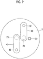
- the two reed valves 40 serving as the plate-shaped member are installed so as to interpose the injection pipe 50 therebetween.
- the injection pipe 50 is located on the rear side in the blowing direction of the refrigerant discharged from the two discharge ports 29, and the refrigerant is blown in the direction away from the injection pipe 50.
- illustration of the retainer 41 is omitted.
- Figs. 8 and 9 unlike a case where only one discharge port 29 is formed in the discharge cover 3, the line connecting one end and the other end of the reed valve 40 and the line connecting the discharge port 29 and the injection pipe 50 are less likely to form the angle of 90° or smaller. Even if the line connecting one end and the other end of the reed valve 40 and the line connecting the discharge port 29 and the injection pipe 50 can form the angle of 90°, there is a possibility that the refrigerant blown out from the discharge port 29 may come into contact with the injection pipe 50.
- Fig. 8 illustrates a case where two reed valves are fixed to the discharge port 29 on the same side
- Fig. 9 illustrates a case where two reed valves are fixed to the discharge port 29 on different sides.
- the injection pipe 50 is installed on a perpendicular bisector of the line connecting the two discharge ports 29. According to this arrangement relationship, the two reed valves 40 can be installed so as to interpose the injection pipe 50 therebetween, and the refrigerant can be blown in the direction away from the injection pipe 50.
- an angle formed between the line connecting one end and the other end of one of the reed valves 40 and the line connecting one end and the other end of the other on of the reed valves 40 is desirably 90° or smaller. In this manner, the refrigerants blown out from the two discharge ports 29 can be blown in the direction away from the injection pipe 50 without interfering with each other.
- the refrigerant blown out from the discharge port 29 does not directly come into contact with the injection pipe 50. Accordingly, the refrigerant flowing inside the injection pipe 50 is less likely to be heated. As a result, the inside of the compression chamber 20 is properly cooled by the refrigerant supplied to the compression chamber 20 after passing through the injection pipe 50. Therefore, it is possible to prevent poor performance of the hermetic scroll compressor 1.
- the discharge pipe 30 is installed so that the refrigerant discharged from the discharge port 29 to the discharge chamber 5 is blown in a direction closer to the discharge pipe 30 by the reed valve 40. That is, the discharge pipe 30 is disposed on the front side in the blowing direction of the refrigerant discharged from the discharge port 29. In this manner, the amount of the refrigerant discharged from the discharge port 29 decreases toward the injection pipe 50. Therefore, the refrigerant flowing inside the injection pipe 50 is much less likely to be heated.
- the discharge pipe 30 is disposed on a side opposite to the injection pipe 50 across the line connecting the two discharge ports 29.
- the discharge pipe 30 is installed on the perpendicular bisector of the line connecting the two discharge ports 29. In this manner, the amount of the refrigerant discharged from the discharge port 29 reliably decreases toward the injection pipe 50. Therefore, the refrigerant flowing inside the injection pipe 50 is much less likely to be heated.
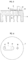
- the present invention is not limited to this example. That is, in a case having no discharge cover 3, as illustrated in Fig. 5 , the reed valve 40 may be installed in the discharge port 24 formed in the fixed scroll 18. Even in this case, the reed valve 40 is installed in the same manner as described above, based on the relationship between the blowing direction of the refrigerant blown out from the discharge port 24 regulated by the reed valve 40 and the position of the injection pipe 50. In addition, the discharge pipe 30 may also be installed in the same manner as described above.
- the refrigerant blown out from the discharge port 24 does not directly come into contact with the injection pipe 50. Accordingly, the refrigerant flowing inside the injection pipe 50 is less likely to be heated. As a result, the inside of the compression chamber 20 is properly cooled by the refrigerant supplied to the compression chamber 20 after passing through the injection pipe 50. Therefore, it is possible to prevent poor performance of the compressor.
Claims (6)
- Verdichter, der Folgendes umfasst:ein Gehäuse (2);einen Scrollverdichtungsmechanismus (7), der im Gehäuse (2) aufgenommen ist;eine Austrittsabdeckung (3) oder eine feste Spirale (18) des Verdichtungsmechanismus (7) mit einem Austrittsanschluss (24, 29), durch den ein Kältemittel, das vom Verdichtungsmechanismus (7) verdichtet wird, geführt wird;eine Austrittskammer (5), die zwischen dem Gehäuse (2) und der Austrittsabdeckung (3) oder der festen Spirale (18) gebildet ist;eine Leitungseinheit, die derart angeordnet ist, dass sie intern durch die Austrittskammer (5) geführt wird, und die mit dem Verdichtungsmechanismus (7) verbunden ist, um das Kältemittel intern zu zirkulieren; undein Membranventil (40), das im Austrittsanschluss (24, 29) der Austrittsabdeckung (3) oder der festen Spirale (18) angeordnet ist und eine Auslegung aufweist, bei der das Kältemittel, das aus dem Austrittsanschluss (24, 29) zur Austrittskammer (5) austritt, in eine Richtung von der Leitungseinheit weg geblasen wird,eine Austrittsleitung (30), die derart installiert ist, dass sie das Gehäuse (2) zur Austrittskammer (5) durchdringt und das Kältemittel in der Austrittskammer (5) von der Austrittskammer (5) nach außen ausgibt, undeine Saugleitung (27), die am Gehäuse (2) installiert ist und das Kältemittel in das Gehäuse (2) saugt,wobei das Membranventil (40) ein plattenförmiges Element aufweist, das das Kältemittel, das aus dem Austrittsanschluss (24, 29) austritt, in eine vorbestimmte Blasrichtung bläst,wobei die Leitungseinheit in der Blasrichtung auf einer Rückseite angeordnet ist,wobei das plattenförmige Element des Membranventils (40) in einer Richtung lang ist und dessen eine Endseite an der Austrittsabdeckung (3) oder an der festen Spirale (18) befestigt ist und die andere Endseite in der Lage ist, den Austrittsanschluss (24, 29) zu öffnen und zu schließen, undwobei eine Linie, die ein Ende und das andere Ende des plattenförmigen Elements verbindet, und eine Linie, die den Austrittsanschluss (24, 29) und die Leitungseinheit, die auf einer Ebene vorsteht, die das plattenförmige Element enthält, verbindet, einen Winkel von 90° oder kleiner bilden,und wobei die Austrittsleitung (30) in der Richtung, in die das Kältemittel aus dem Austrittsanschluss (24, 29) austritt, auf der Vorderseite angeordnet ist, derart, dass das Kältemittel, das aus dem Austrittsanschluss (24, 29) zur Austrittskammer (5) austritt, vom Membranventil (40) in eine Richtung zur Austrittsleitung (30) geblasen wird.
- Verdichter, der Folgendes umfasst:ein Gehäuse (2);einen Scrollverdichtungsmechanismus (7), der im Gehäuse (2) aufgenommen ist;eine Austrittsabdeckung (3) oder eine feste Spirale (18) des Verdichtungsmechanismus (7) mit zwei Austrittsanschlüssen (24, 29), durch die ein Kältemittel, das vom Verdichtungsmechanismus (7) verdichtet wird, geführt wird;eine Austrittskammer (5), die zwischen dem Gehäuse (2) und der Austrittsabdeckung (3) oder der festen Spirale (18) gebildet ist;eine Leitungseinheit, die derart angeordnet ist, dass sie intern durch die Austrittskammer (5) geführt wird, und die mit dem Verdichtungsmechanismus (7) verbunden ist, um das Kältemittel intern zu zirkulieren; undein Membranventil (40), das im Austrittsanschluss (24, 29) der Austrittsabdeckung (3) oder der festen Spirale (18) angeordnet ist und eine Auslegung aufweist, bei der das Kältemittel, das aus dem Austrittsanschluss (24, 29) zur Austrittskammer (5) austritt, in eine Richtung von der Leitungseinheit weg geblasen wird,wobei das Membranventil (40) ein plattenförmiges Element aufweist, das das Kältemittel, das aus dem Austrittsanschluss (24, 29) austritt, in eine vorbestimmte Blasrichtung bläst,wobei die Leitungseinheit in der Blasrichtung auf einer Rückseite angeordnet ist,wobei das plattenförmige Element des Membranventils (40) in einer Richtung lang ist und dessen eine Endseite an der Austrittsabdeckung (3) oder an der festen Spirale (18) befestigt ist und die andere Endseite in der Lage ist, den Austrittsanschluss (24, 29) zu öffnen und zu schließen, undwobei die Austrittsanschlüsse (24, 29) jeweils an zwei Stellen angeordnet sind und die Membranventile (40) für jeden der Austrittsanschlüsse (24, 29) einzeln angeordnet sind und die plattenförmigen Elemente der zwei Membranventile (40) derart installiert sind, dass sie die Leitungseinheit dazwischen einschließen.
- Verdichter nach Anspruch 2,
wobei die Leitungseinheit auf einer Mittelsenkrechten eines Liniensegments, das die zwei Austrittsanschlüsse (24, 29) verbindet, installiert ist. - Verdichter nach Anspruch 2 oder 3,
wobei ein Winkel, der zwischen einer Linie, die ein Ende und das andere Ende von einem der plattenförmigen Elemente verbindet, und einer Linie, die ein Ende und das andere Ende des anderen der plattenförmigen Elemente verbindet, gebildet ist, 90° oder kleiner ist. - Verdichter nach einem der Ansprüche 2 bis 4, der ferner Folgendes umfasst:eine Austrittsleitung (30), die derart installiert ist, dass sie das Gehäuse (2) durchdringt und das Kältemittel in der Austrittskammer (5) von der Austrittskammer (5) nach außen ausgibt,wobei die Austrittsleitung (30) derart installiert ist, dass das Kältemittel, das aus dem Austrittsanschluss (24, 29) zur Austrittskammer (5) austritt, vom Membranventil (40) in eine Richtung zur Austrittsleitung (30) geblasen wird.
- Verdichter nach Anspruch 5,
wobei die Austrittsleitung (30) auf einer Seite gegenüber der Leitungseinheit über eine Linie, die die zwei Austrittsanschlüsse (24, 29) verbindet, installiert ist.
Applications Claiming Priority (2)
| Application Number | Priority Date | Filing Date | Title |
|---|---|---|---|
| JP2016042114A JP6710545B2 (ja) | 2016-03-04 | 2016-03-04 | 圧縮機 |
| PCT/JP2017/008085 WO2017150602A1 (ja) | 2016-03-04 | 2017-03-01 | 圧縮機 |
Publications (3)
| Publication Number | Publication Date |
|---|---|
| EP3382205A1 EP3382205A1 (de) | 2018-10-03 |
| EP3382205A4 EP3382205A4 (de) | 2018-11-07 |
| EP3382205B1 true EP3382205B1 (de) | 2020-11-18 |
Family
ID=59744113
Family Applications (1)
| Application Number | Title | Priority Date | Filing Date |
|---|---|---|---|
| EP17760066.5A Active EP3382205B1 (de) | 2016-03-04 | 2017-03-01 | Verdichter |
Country Status (4)
| Country | Link |
|---|---|
| EP (1) | EP3382205B1 (de) |
| JP (1) | JP6710545B2 (de) |
| CN (1) | CN108474378B (de) |
| WO (1) | WO2017150602A1 (de) |
Families Citing this family (6)
| Publication number | Priority date | Publication date | Assignee | Title |
|---|---|---|---|---|
| JP7123636B2 (ja) * | 2018-06-05 | 2022-08-23 | 三菱重工サーマルシステムズ株式会社 | 圧縮機及び圧縮機の製造方法 |
| JP7154868B2 (ja) * | 2018-08-02 | 2022-10-18 | 三菱重工サーマルシステムズ株式会社 | 圧縮機 |
| KR20210012292A (ko) * | 2019-07-24 | 2021-02-03 | 한온시스템 주식회사 | 스크롤 압축기 |
| KR20210105565A (ko) * | 2020-02-19 | 2021-08-27 | 한온시스템 주식회사 | 스크롤 압축기 |
| US11384759B2 (en) * | 2020-03-10 | 2022-07-12 | Hanon Systems | Vapor injection double reed valve plate |
| JP7366238B2 (ja) * | 2020-03-27 | 2023-10-20 | 三菱電機株式会社 | スクロール圧縮機 |
Family Cites Families (10)
| Publication number | Priority date | Publication date | Assignee | Title |
|---|---|---|---|---|
| JPS58187594A (ja) * | 1982-04-28 | 1983-11-01 | Hitachi Ltd | スクロ−ル圧縮機 |
| JPH0364686A (ja) * | 1989-07-31 | 1991-03-20 | Sanden Corp | スクロール型圧縮機 |
| US5741120A (en) * | 1995-06-07 | 1998-04-21 | Copeland Corporation | Capacity modulated scroll machine |
| JP2956555B2 (ja) * | 1995-12-05 | 1999-10-04 | 松下電器産業株式会社 | スクロール気体圧縮機 |
| US5855475A (en) * | 1995-12-05 | 1999-01-05 | Matsushita Electric Industrial Co., Ltd. | Scroll compressor having bypass valves |
| KR100343688B1 (ko) * | 1999-10-04 | 2002-07-19 | 엘지전자주식회사 | 스크롤 압축기의 중간압 배압구조 |
| JP3876923B2 (ja) * | 2005-05-17 | 2007-02-07 | ダイキン工業株式会社 | 回転式圧縮機 |
| WO2006123519A1 (ja) * | 2005-05-17 | 2006-11-23 | Daikin Industries, Ltd. | 回転式圧縮機 |
| JP5314326B2 (ja) * | 2008-05-30 | 2013-10-16 | 三菱重工業株式会社 | 冷媒圧縮機 |
| JP5768863B2 (ja) * | 2013-11-18 | 2015-08-26 | 株式会社豊田自動織機 | 電動圧縮機 |
-
2016
- 2016-03-04 JP JP2016042114A patent/JP6710545B2/ja active Active
-
2017
- 2017-03-01 CN CN201780005285.XA patent/CN108474378B/zh active Active
- 2017-03-01 WO PCT/JP2017/008085 patent/WO2017150602A1/ja active Application Filing
- 2017-03-01 EP EP17760066.5A patent/EP3382205B1/de active Active
Non-Patent Citations (1)
| Title |
|---|
| None * |
Also Published As
| Publication number | Publication date |
|---|---|
| JP6710545B2 (ja) | 2020-06-17 |
| CN108474378B (zh) | 2020-10-27 |
| CN108474378A (zh) | 2018-08-31 |
| EP3382205A4 (de) | 2018-11-07 |
| WO2017150602A1 (ja) | 2017-09-08 |
| JP2017155719A (ja) | 2017-09-07 |
| EP3382205A1 (de) | 2018-10-03 |
Similar Documents
| Publication | Publication Date | Title |
|---|---|---|
| EP3382205B1 (de) | Verdichter | |
| US8109116B2 (en) | Dual compressor air conditioning system with oil level regulation | |
| US10378539B2 (en) | System including high-side and low-side compressors | |
| EP2055956B1 (de) | Mehrstufiger kompressor | |
| EP2392827B1 (de) | Spiralverdichter | |
| WO2009096167A1 (ja) | 膨張機一体型圧縮機およびそれを用いた冷凍サイクル装置 | |
| EP2172653A1 (de) | Mehrstufiger verdichter | |
| KR101971819B1 (ko) | 스크롤 압축기 | |
| US7588428B2 (en) | Rotary fluid device performing compression and expansion of fluid within a common cylinder | |
| US9435337B2 (en) | Scroll compressor | |
| JP4930314B2 (ja) | 容積型膨張機、膨張機一体型圧縮機、および冷凍サイクル装置 | |
| US20160298626A1 (en) | Scroll compressor | |
| US8245528B2 (en) | Fluid machine | |
| EP2322804B1 (de) | Mehrstufiger verdichter | |
| JP4722173B2 (ja) | 冷凍サイクル装置 | |
| JP2009127440A (ja) | スクロール圧縮機 | |
| JP4811200B2 (ja) | 電動圧縮機 | |
| CN107893758B (zh) | 涡旋压缩机及具有其的空调器 | |
| JP4879078B2 (ja) | 圧縮機 | |
| JP2019019768A (ja) | スクロール圧縮機 | |
| JP2006037896A (ja) | スクロール圧縮機 | |
| JP2012211569A (ja) | ロータリ圧縮機 | |
| JP4924450B2 (ja) | 膨張機 | |
| JP2014105692A (ja) | スクロール圧縮機 | |
| JP2014101804A (ja) | スクロール型圧縮機 |
Legal Events
| Date | Code | Title | Description |
|---|---|---|---|
| STAA | Information on the status of an ep patent application or granted ep patent |
Free format text: STATUS: THE INTERNATIONAL PUBLICATION HAS BEEN MADE |
|
| PUAI | Public reference made under article 153(3) epc to a published international application that has entered the european phase |
Free format text: ORIGINAL CODE: 0009012 |
|
| STAA | Information on the status of an ep patent application or granted ep patent |
Free format text: STATUS: REQUEST FOR EXAMINATION WAS MADE |
|
| 17P | Request for examination filed |
Effective date: 20180629 |
|
| AK | Designated contracting states |
Kind code of ref document: A1 Designated state(s): AL AT BE BG CH CY CZ DE DK EE ES FI FR GB GR HR HU IE IS IT LI LT LU LV MC MK MT NL NO PL PT RO RS SE SI SK SM TR |
|
| AX | Request for extension of the european patent |
Extension state: BA ME |
|
| A4 | Supplementary search report drawn up and despatched |
Effective date: 20181005 |
|
| RIC1 | Information provided on ipc code assigned before grant |
Ipc: F04C 29/04 20060101ALI20180929BHEP Ipc: F04C 29/12 20060101ALI20180929BHEP Ipc: F04C 18/02 20060101AFI20180929BHEP Ipc: F04C 23/00 20060101ALI20180929BHEP |
|
| STAA | Information on the status of an ep patent application or granted ep patent |
Free format text: STATUS: EXAMINATION IS IN PROGRESS |
|
| DAV | Request for validation of the european patent (deleted) | ||
| DAX | Request for extension of the european patent (deleted) | ||
| 17Q | First examination report despatched |
Effective date: 20190522 |
|
| GRAP | Despatch of communication of intention to grant a patent |
Free format text: ORIGINAL CODE: EPIDOSNIGR1 |
|
| STAA | Information on the status of an ep patent application or granted ep patent |
Free format text: STATUS: GRANT OF PATENT IS INTENDED |
|
| INTG | Intention to grant announced |
Effective date: 20200610 |
|
| GRAS | Grant fee paid |
Free format text: ORIGINAL CODE: EPIDOSNIGR3 |
|
| GRAA | (expected) grant |
Free format text: ORIGINAL CODE: 0009210 |
|
| STAA | Information on the status of an ep patent application or granted ep patent |
Free format text: STATUS: THE PATENT HAS BEEN GRANTED |
|
| AK | Designated contracting states |
Kind code of ref document: B1 Designated state(s): AL AT BE BG CH CY CZ DE DK EE ES FI FR GB GR HR HU IE IS IT LI LT LU LV MC MK MT NL NO PL PT RO RS SE SI SK SM TR |
|
| REG | Reference to a national code |
Ref country code: GB Ref legal event code: FG4D |
|
| REG | Reference to a national code |
Ref country code: CH Ref legal event code: EP |
|
| REG | Reference to a national code |
Ref country code: IE Ref legal event code: FG4D |
|
| REG | Reference to a national code |
Ref country code: DE Ref legal event code: R096 Ref document number: 602017027839 Country of ref document: DE |
|
| REG | Reference to a national code |
Ref country code: AT Ref legal event code: REF Ref document number: 1336076 Country of ref document: AT Kind code of ref document: T Effective date: 20201215 |
|
| REG | Reference to a national code |
Ref country code: AT Ref legal event code: MK05 Ref document number: 1336076 Country of ref document: AT Kind code of ref document: T Effective date: 20201118 |
|
| REG | Reference to a national code |
Ref country code: NL Ref legal event code: MP Effective date: 20201118 |
|
| PG25 | Lapsed in a contracting state [announced via postgrant information from national office to epo] |
Ref country code: GR Free format text: LAPSE BECAUSE OF FAILURE TO SUBMIT A TRANSLATION OF THE DESCRIPTION OR TO PAY THE FEE WITHIN THE PRESCRIBED TIME-LIMIT Effective date: 20210219 Ref country code: FI Free format text: LAPSE BECAUSE OF FAILURE TO SUBMIT A TRANSLATION OF THE DESCRIPTION OR TO PAY THE FEE WITHIN THE PRESCRIBED TIME-LIMIT Effective date: 20201118 Ref country code: PT Free format text: LAPSE BECAUSE OF FAILURE TO SUBMIT A TRANSLATION OF THE DESCRIPTION OR TO PAY THE FEE WITHIN THE PRESCRIBED TIME-LIMIT Effective date: 20210318 Ref country code: RS Free format text: LAPSE BECAUSE OF FAILURE TO SUBMIT A TRANSLATION OF THE DESCRIPTION OR TO PAY THE FEE WITHIN THE PRESCRIBED TIME-LIMIT Effective date: 20201118 Ref country code: NO Free format text: LAPSE BECAUSE OF FAILURE TO SUBMIT A TRANSLATION OF THE DESCRIPTION OR TO PAY THE FEE WITHIN THE PRESCRIBED TIME-LIMIT Effective date: 20210218 |
|
| PG25 | Lapsed in a contracting state [announced via postgrant information from national office to epo] |
Ref country code: AT Free format text: LAPSE BECAUSE OF FAILURE TO SUBMIT A TRANSLATION OF THE DESCRIPTION OR TO PAY THE FEE WITHIN THE PRESCRIBED TIME-LIMIT Effective date: 20201118 Ref country code: BG Free format text: LAPSE BECAUSE OF FAILURE TO SUBMIT A TRANSLATION OF THE DESCRIPTION OR TO PAY THE FEE WITHIN THE PRESCRIBED TIME-LIMIT Effective date: 20210218 Ref country code: IS Free format text: LAPSE BECAUSE OF FAILURE TO SUBMIT A TRANSLATION OF THE DESCRIPTION OR TO PAY THE FEE WITHIN THE PRESCRIBED TIME-LIMIT Effective date: 20210318 Ref country code: PL Free format text: LAPSE BECAUSE OF FAILURE TO SUBMIT A TRANSLATION OF THE DESCRIPTION OR TO PAY THE FEE WITHIN THE PRESCRIBED TIME-LIMIT Effective date: 20201118 Ref country code: LV Free format text: LAPSE BECAUSE OF FAILURE TO SUBMIT A TRANSLATION OF THE DESCRIPTION OR TO PAY THE FEE WITHIN THE PRESCRIBED TIME-LIMIT Effective date: 20201118 Ref country code: SE Free format text: LAPSE BECAUSE OF FAILURE TO SUBMIT A TRANSLATION OF THE DESCRIPTION OR TO PAY THE FEE WITHIN THE PRESCRIBED TIME-LIMIT Effective date: 20201118 |
|
| REG | Reference to a national code |
Ref country code: LT Ref legal event code: MG9D |
|
| PG25 | Lapsed in a contracting state [announced via postgrant information from national office to epo] |
Ref country code: HR Free format text: LAPSE BECAUSE OF FAILURE TO SUBMIT A TRANSLATION OF THE DESCRIPTION OR TO PAY THE FEE WITHIN THE PRESCRIBED TIME-LIMIT Effective date: 20201118 |
|
| PG25 | Lapsed in a contracting state [announced via postgrant information from national office to epo] |
Ref country code: SK Free format text: LAPSE BECAUSE OF FAILURE TO SUBMIT A TRANSLATION OF THE DESCRIPTION OR TO PAY THE FEE WITHIN THE PRESCRIBED TIME-LIMIT Effective date: 20201118 Ref country code: RO Free format text: LAPSE BECAUSE OF FAILURE TO SUBMIT A TRANSLATION OF THE DESCRIPTION OR TO PAY THE FEE WITHIN THE PRESCRIBED TIME-LIMIT Effective date: 20201118 Ref country code: CZ Free format text: LAPSE BECAUSE OF FAILURE TO SUBMIT A TRANSLATION OF THE DESCRIPTION OR TO PAY THE FEE WITHIN THE PRESCRIBED TIME-LIMIT Effective date: 20201118 Ref country code: EE Free format text: LAPSE BECAUSE OF FAILURE TO SUBMIT A TRANSLATION OF THE DESCRIPTION OR TO PAY THE FEE WITHIN THE PRESCRIBED TIME-LIMIT Effective date: 20201118 Ref country code: LT Free format text: LAPSE BECAUSE OF FAILURE TO SUBMIT A TRANSLATION OF THE DESCRIPTION OR TO PAY THE FEE WITHIN THE PRESCRIBED TIME-LIMIT Effective date: 20201118 Ref country code: SM Free format text: LAPSE BECAUSE OF FAILURE TO SUBMIT A TRANSLATION OF THE DESCRIPTION OR TO PAY THE FEE WITHIN THE PRESCRIBED TIME-LIMIT Effective date: 20201118 |
|
| REG | Reference to a national code |
Ref country code: DE Ref legal event code: R097 Ref document number: 602017027839 Country of ref document: DE |
|
| PG25 | Lapsed in a contracting state [announced via postgrant information from national office to epo] |
Ref country code: DK Free format text: LAPSE BECAUSE OF FAILURE TO SUBMIT A TRANSLATION OF THE DESCRIPTION OR TO PAY THE FEE WITHIN THE PRESCRIBED TIME-LIMIT Effective date: 20201118 |
|
| PLBE | No opposition filed within time limit |
Free format text: ORIGINAL CODE: 0009261 |
|
| STAA | Information on the status of an ep patent application or granted ep patent |
Free format text: STATUS: NO OPPOSITION FILED WITHIN TIME LIMIT |
|
| 26N | No opposition filed |
Effective date: 20210819 |
|
| PG25 | Lapsed in a contracting state [announced via postgrant information from national office to epo] |
Ref country code: NL Free format text: LAPSE BECAUSE OF FAILURE TO SUBMIT A TRANSLATION OF THE DESCRIPTION OR TO PAY THE FEE WITHIN THE PRESCRIBED TIME-LIMIT Effective date: 20201118 Ref country code: AL Free format text: LAPSE BECAUSE OF FAILURE TO SUBMIT A TRANSLATION OF THE DESCRIPTION OR TO PAY THE FEE WITHIN THE PRESCRIBED TIME-LIMIT Effective date: 20201118 Ref country code: IT Free format text: LAPSE BECAUSE OF FAILURE TO SUBMIT A TRANSLATION OF THE DESCRIPTION OR TO PAY THE FEE WITHIN THE PRESCRIBED TIME-LIMIT Effective date: 20201118 Ref country code: MC Free format text: LAPSE BECAUSE OF FAILURE TO SUBMIT A TRANSLATION OF THE DESCRIPTION OR TO PAY THE FEE WITHIN THE PRESCRIBED TIME-LIMIT Effective date: 20201118 |
|
| REG | Reference to a national code |
Ref country code: CH Ref legal event code: PL |
|
| PG25 | Lapsed in a contracting state [announced via postgrant information from national office to epo] |
Ref country code: SI Free format text: LAPSE BECAUSE OF FAILURE TO SUBMIT A TRANSLATION OF THE DESCRIPTION OR TO PAY THE FEE WITHIN THE PRESCRIBED TIME-LIMIT Effective date: 20201118 |
|
| REG | Reference to a national code |
Ref country code: BE Ref legal event code: MM Effective date: 20210331 |
|
| PG25 | Lapsed in a contracting state [announced via postgrant information from national office to epo] |
Ref country code: IE Free format text: LAPSE BECAUSE OF NON-PAYMENT OF DUE FEES Effective date: 20210301 Ref country code: ES Free format text: LAPSE BECAUSE OF FAILURE TO SUBMIT A TRANSLATION OF THE DESCRIPTION OR TO PAY THE FEE WITHIN THE PRESCRIBED TIME-LIMIT Effective date: 20201118 Ref country code: LU Free format text: LAPSE BECAUSE OF NON-PAYMENT OF DUE FEES Effective date: 20210301 Ref country code: LI Free format text: LAPSE BECAUSE OF NON-PAYMENT OF DUE FEES Effective date: 20210331 Ref country code: CH Free format text: LAPSE BECAUSE OF NON-PAYMENT OF DUE FEES Effective date: 20210331 |
|
| PG25 | Lapsed in a contracting state [announced via postgrant information from national office to epo] |
Ref country code: IS Free format text: LAPSE BECAUSE OF FAILURE TO SUBMIT A TRANSLATION OF THE DESCRIPTION OR TO PAY THE FEE WITHIN THE PRESCRIBED TIME-LIMIT Effective date: 20210318 |
|
| PG25 | Lapsed in a contracting state [announced via postgrant information from national office to epo] |
Ref country code: BE Free format text: LAPSE BECAUSE OF NON-PAYMENT OF DUE FEES Effective date: 20210331 |
|
| REG | Reference to a national code |
Ref country code: DE Ref legal event code: R082 Ref document number: 602017027839 Country of ref document: DE Representative=s name: CBDL PATENTANWAELTE GBR, DE |
|
| PGFP | Annual fee paid to national office [announced via postgrant information from national office to epo] |
Ref country code: FR Payment date: 20230208 Year of fee payment: 7 |
|
| PGFP | Annual fee paid to national office [announced via postgrant information from national office to epo] |
Ref country code: GB Payment date: 20230202 Year of fee payment: 7 Ref country code: DE Payment date: 20230131 Year of fee payment: 7 |
|
| PG25 | Lapsed in a contracting state [announced via postgrant information from national office to epo] |
Ref country code: CY Free format text: LAPSE BECAUSE OF FAILURE TO SUBMIT A TRANSLATION OF THE DESCRIPTION OR TO PAY THE FEE WITHIN THE PRESCRIBED TIME-LIMIT Effective date: 20201118 |
|
| PG25 | Lapsed in a contracting state [announced via postgrant information from national office to epo] |
Ref country code: HU Free format text: LAPSE BECAUSE OF FAILURE TO SUBMIT A TRANSLATION OF THE DESCRIPTION OR TO PAY THE FEE WITHIN THE PRESCRIBED TIME-LIMIT; INVALID AB INITIO Effective date: 20170301 |