WO2017150602A1 - 圧縮機 - Google Patents
圧縮機 Download PDFInfo
- Publication number
- WO2017150602A1 WO2017150602A1 PCT/JP2017/008085 JP2017008085W WO2017150602A1 WO 2017150602 A1 WO2017150602 A1 WO 2017150602A1 JP 2017008085 W JP2017008085 W JP 2017008085W WO 2017150602 A1 WO2017150602 A1 WO 2017150602A1
- Authority
- WO
- WIPO (PCT)
- Prior art keywords
- discharge
- refrigerant
- discharge port
- reed valve
- pipe
- Prior art date
Links
Images


Classifications
-
- F—MECHANICAL ENGINEERING; LIGHTING; HEATING; WEAPONS; BLASTING
- F04—POSITIVE - DISPLACEMENT MACHINES FOR LIQUIDS; PUMPS FOR LIQUIDS OR ELASTIC FLUIDS
- F04C—ROTARY-PISTON, OR OSCILLATING-PISTON, POSITIVE-DISPLACEMENT MACHINES FOR LIQUIDS; ROTARY-PISTON, OR OSCILLATING-PISTON, POSITIVE-DISPLACEMENT PUMPS
- F04C18/00—Rotary-piston pumps specially adapted for elastic fluids
- F04C18/02—Rotary-piston pumps specially adapted for elastic fluids of arcuate-engagement type, i.e. with circular translatory movement of co-operating members, each member having the same number of teeth or tooth-equivalents
-
- F—MECHANICAL ENGINEERING; LIGHTING; HEATING; WEAPONS; BLASTING
- F04—POSITIVE - DISPLACEMENT MACHINES FOR LIQUIDS; PUMPS FOR LIQUIDS OR ELASTIC FLUIDS
- F04C—ROTARY-PISTON, OR OSCILLATING-PISTON, POSITIVE-DISPLACEMENT MACHINES FOR LIQUIDS; ROTARY-PISTON, OR OSCILLATING-PISTON, POSITIVE-DISPLACEMENT PUMPS
- F04C23/00—Combinations of two or more pumps, each being of rotary-piston or oscillating-piston type, specially adapted for elastic fluids; Pumping installations specially adapted for elastic fluids; Multi-stage pumps specially adapted for elastic fluids
- F04C23/008—Hermetic pumps
-
- F—MECHANICAL ENGINEERING; LIGHTING; HEATING; WEAPONS; BLASTING
- F04—POSITIVE - DISPLACEMENT MACHINES FOR LIQUIDS; PUMPS FOR LIQUIDS OR ELASTIC FLUIDS
- F04C—ROTARY-PISTON, OR OSCILLATING-PISTON, POSITIVE-DISPLACEMENT MACHINES FOR LIQUIDS; ROTARY-PISTON, OR OSCILLATING-PISTON, POSITIVE-DISPLACEMENT PUMPS
- F04C18/00—Rotary-piston pumps specially adapted for elastic fluids
- F04C18/02—Rotary-piston pumps specially adapted for elastic fluids of arcuate-engagement type, i.e. with circular translatory movement of co-operating members, each member having the same number of teeth or tooth-equivalents
- F04C18/0207—Rotary-piston pumps specially adapted for elastic fluids of arcuate-engagement type, i.e. with circular translatory movement of co-operating members, each member having the same number of teeth or tooth-equivalents both members having co-operating elements in spiral form
- F04C18/0215—Rotary-piston pumps specially adapted for elastic fluids of arcuate-engagement type, i.e. with circular translatory movement of co-operating members, each member having the same number of teeth or tooth-equivalents both members having co-operating elements in spiral form where only one member is moving
-
- F—MECHANICAL ENGINEERING; LIGHTING; HEATING; WEAPONS; BLASTING
- F04—POSITIVE - DISPLACEMENT MACHINES FOR LIQUIDS; PUMPS FOR LIQUIDS OR ELASTIC FLUIDS
- F04C—ROTARY-PISTON, OR OSCILLATING-PISTON, POSITIVE-DISPLACEMENT MACHINES FOR LIQUIDS; ROTARY-PISTON, OR OSCILLATING-PISTON, POSITIVE-DISPLACEMENT PUMPS
- F04C29/00—Component parts, details or accessories of pumps or pumping installations, not provided for in groups F04C18/00 - F04C28/00
- F04C29/04—Heating; Cooling; Heat insulation
- F04C29/042—Heating; Cooling; Heat insulation by injecting a fluid
-
- F—MECHANICAL ENGINEERING; LIGHTING; HEATING; WEAPONS; BLASTING
- F04—POSITIVE - DISPLACEMENT MACHINES FOR LIQUIDS; PUMPS FOR LIQUIDS OR ELASTIC FLUIDS
- F04C—ROTARY-PISTON, OR OSCILLATING-PISTON, POSITIVE-DISPLACEMENT MACHINES FOR LIQUIDS; ROTARY-PISTON, OR OSCILLATING-PISTON, POSITIVE-DISPLACEMENT PUMPS
- F04C29/00—Component parts, details or accessories of pumps or pumping installations, not provided for in groups F04C18/00 - F04C28/00
- F04C29/12—Arrangements for admission or discharge of the working fluid, e.g. constructional features of the inlet or outlet
- F04C29/124—Arrangements for admission or discharge of the working fluid, e.g. constructional features of the inlet or outlet with inlet and outlet valves specially adapted for rotary or oscillating piston pumps
- F04C29/126—Arrangements for admission or discharge of the working fluid, e.g. constructional features of the inlet or outlet with inlet and outlet valves specially adapted for rotary or oscillating piston pumps of the non-return type
- F04C29/128—Arrangements for admission or discharge of the working fluid, e.g. constructional features of the inlet or outlet with inlet and outlet valves specially adapted for rotary or oscillating piston pumps of the non-return type of the elastic type, e.g. reed valves
-
- F—MECHANICAL ENGINEERING; LIGHTING; HEATING; WEAPONS; BLASTING
- F04—POSITIVE - DISPLACEMENT MACHINES FOR LIQUIDS; PUMPS FOR LIQUIDS OR ELASTIC FLUIDS
- F04C—ROTARY-PISTON, OR OSCILLATING-PISTON, POSITIVE-DISPLACEMENT MACHINES FOR LIQUIDS; ROTARY-PISTON, OR OSCILLATING-PISTON, POSITIVE-DISPLACEMENT PUMPS
- F04C2240/00—Components
- F04C2240/80—Other components
- F04C2240/806—Pipes for fluids; Fittings therefor
Definitions
- the present invention relates to a compressor.
- the closed scroll compressor is used, for example, in a refrigeration system, an air conditioner, etc., and compresses and discharges a refrigerant supplied from the outside.
- a discharge chamber is formed above the scroll compression mechanism in a closed housing.
- the discharge chamber is a space surrounded by the scroll type compression mechanism and the housing, and the refrigerant compressed by the compression mechanism is supplied to temporarily store the refrigerant, and then discharge the refrigerant from the discharge pipe to the outside.
- Patent Documents 1 and 2 listed below disclose that, in a scroll compressor, an injection pipe for introducing a refrigerant at an intermediate pressure from the outside into the compression chamber of the compression mechanism is provided. By supplying the liquid refrigerant to the compression chamber through the injection pipe, the temperature of the refrigerant is reduced by the latent heat when the liquid refrigerant evaporates, and the inside of the compression chamber is cooled.
- a volume control pipe (hereinafter referred to as a "bypass pipe”) may be provided to extract the refrigerant at an intermediate pressure of the compression chamber to the outside.
- the medium pressure refrigerant extracted to the outside is returned to the suction side of the compressor. This enables capacity control operation of the compressor.
- An injection pipe and a bypass pipe provided in the hermetic scroll compressor are provided through the upper portion of the housing and the discharge chamber, and are connected to the compression mechanism. Therefore, the refrigerant passing through the injection pipe and the bypass pipe is heated by the high temperature refrigerant in the discharge chamber.
- the refrigerant discharged from the discharge port 29 is installed toward the injection pipe 50 or the bypass pipe by the reed valve 40, the injection pipe 50 or the bypass pipe The passing refrigerant is likely to be heated.
- the present invention has been made in view of such circumstances, and it is possible to suppress the temperature rise of the refrigerant passing through a pipe section such as an injection pipe and a bypass pipe installed inside the discharge chamber.
- the purpose is to provide a machine.
- a compressor of the present invention adopts the following means. That is, the compressor according to one aspect of the present invention includes a housing, a scroll-type compression mechanism housed in the housing, and a discharge cover or the discharge cover provided with a discharge port through which the refrigerant compressed by the compression mechanism passes.
- a fixed scroll of a compression mechanism a discharge chamber formed between the housing and the discharge cover or the fixed scroll, a piping portion which passes through the discharge chamber and through which the refrigerant flows; And a reed valve provided at the discharge port of the discharge cover or the fixed scroll and having a configuration in which the refrigerant discharged from the discharge port to the discharge chamber is blown out in a direction away from the piping portion.
- the refrigerant compressed by the compression mechanism is formed between the housing and the discharge cover or between the housing and the fixed scroll of the compression mechanism from the discharge port provided in the discharge cover or the fixed scroll of the compression mechanism. It is discharged into the discharge chamber. At this time, the refrigerant discharged from the discharge port to the discharge chamber is blown out in the direction away from the piping portion by the reed valve provided at the discharge port. Therefore, since the high temperature refrigerant discharged from the discharge port does not directly go to the piping part at the shortest distance, the refrigerant passing through the piping part is not easily heated.
- the reed valve may have a plate-like member that blows out the refrigerant discharged from the discharge port in a predetermined blowing direction, and the piping portion may be provided on the rear side in the blowing direction.
- the refrigerant discharged from the discharge port is blown out in the predetermined blowing direction by the plate-like member of the reed valve. Then, since the piping portion is provided on the rear side in the predetermined blowing direction of the refrigerant, the refrigerant discharged from the discharge port to the discharge chamber does not directly go to the piping portion, so the refrigerant passing through the piping portion is heated Hateful.
- the plate-like member of the reed valve is long in one direction, one end thereof is fixed to the discharge cover or the fixed scroll, and the other end can be opened and closed with respect to the discharge port.
- the line connecting the one end and the other end and the line connecting the discharge port and the piping portion may be 90 ° or less.
- the plate-like member of the reed valve is long in one direction, one end is fixed to the discharge cover or the fixed scroll, the other end can be opened and closed with respect to the discharge port, and the discharge port is
- the reed valve is provided at two places, one at each of the discharge ports, the plate-like members of the two reed valves may be installed so as to sandwich the pipe portion.
- the above-mentioned piping part may be installed on a perpendicular bisector of a line segment which connects two above-mentioned discharge mouths.
- the angle formed by the line connecting the one end and the other end of one plate member and the line connecting the one end and the other end of the other plate member may be 90 ° or less.
- the discharge valve further includes a discharge pipe installed through the housing and discharging the refrigerant in the discharge chamber to the outside, and the refrigerant discharged from the discharge port to the discharge chamber is discharged by the reed valve.
- the discharge pipe may be installed so as to blow out in a direction approaching the pipe.
- the discharge valve further includes a discharge pipe installed through the housing and discharging the refrigerant in the discharge chamber to the outside, and the refrigerant discharged from the discharge port to the discharge chamber is discharged by the reed valve.
- the discharge pipe is installed so as to be blown out in a direction approaching the pipe, and the discharge pipe is installed on the opposite side of the piping section with a line connecting the two discharge ports interposed therebetween. It is also good.
- the present invention it is possible to suppress the temperature rise of the refrigerant passing through the piping portion such as the injection pipe and the bypass pipe, which is installed inside the discharge chamber.
- a hermetic scroll compressor 1 as a scroll fluid machine includes a vertically elongated cylindrical hermetic housing 2 whose bottom is sealed by a lower cover.
- the upper portion of the sealed housing 2 is sealed by a discharge cover 3 and an upper cover 4, and a discharge chamber 5 is formed between the discharge cover 3 and the upper cover 4 for discharging a compressed high-pressure gas. .
- An upper bearing member (frame member) 6 is fixedly installed at the upper portion in the sealed housing 2, and the scroll compression mechanism 7 is incorporated via the upper bearing member 6, and the stator 8 and the rotor 9 are formed at the lower portion.
- An electric motor 10 is provided. The electric motor 10 is incorporated by the stator 8 being fixedly installed in the closed housing 2, and the crankshaft 11 is fixed to the rotor 9.
- crank pin 12 whose axis is eccentric by a predetermined dimension is provided, and the scroll compression mechanism 7 is driven by the electric motor 10 by connecting the crank pin 12 to the scroll compression mechanism 7. It is made possible.
- the upper portion of the crankshaft 11 is rotatably supported by the journal bearing portion 6A of the upper bearing member 6, and the lower end portion is rotatably supported by the lower journal bearing 13 provided at the lower portion of the sealed housing 2. ing.
- a positive displacement oil supply pump 14 is provided, and the lubricating oil 15 filled in the bottom of the sealed housing 2 is sucked through the suction pipe 16 It is configured to discharge into a flow passage 17 which is bored in the shaft 11 along the axial direction.
- the lubricating oil 15 can be supplied to a portion requiring lubrication such as the upper bearing member 6, the scroll compression mechanism 7 and the lower journal bearing 13 through the flow passage 17.
- the scroll compression mechanism 7 has the upper bearing member 6 as one component, and is slidably supported by the fixed scroll 18 fixedly installed on the upper bearing member 6 and the thrust bearing portion 6B of the upper bearing member 6 Is interposed between the upper bearing member 6 and the orbiting scroll 19 so as to prevent rotation of the orbiting scroll 19 and to rotate the orbiting orbit.
- the rotational force of the crankshaft 11 is provided to the orbiting scroll 19 provided between the rotation preventing mechanism 21 such as an acceptable Oldham ring, and the bearing boss 19C provided on the crank pin 12 of the crankshaft 11 and the back surface of the orbiting scroll 19.
- the fixed scroll 18 is provided with a drive bush 22 and a pivot bearing (needle bearing) 23 for It is installed on the upper bearing member 6 in a state connected to the scan charge cover 3.
- the fixed scroll 18 includes an end plate 18A and a spiral wrap 18B erected on the end plate 18A.
- a discharge port 24 is provided at the center of the end plate 18A, and wrap teeth of the spiral wrap 18B are provided.
- the tip seal 25 is installed on the front surface.
- the orbiting scroll 19 also includes an end plate 19A and a spiral wrap 19B erected on the end plate 19A.
- a bearing boss 19C is provided on the back of the end plate 19A, and the wrap of the spiral wrap 19B is provided.
- the tip seal 26 is installed on the tooth tip surface.
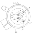
- the scroll compression mechanism 7 opens the refrigerant gas sucked into the sealed housing 2 through the suction pipe 27 opened at a position facing the stator winding 8A of the electric motor 10 into the sealed housing 2. It is drawn into the compression chamber 20 from the suction port 28 and compressed into a high temperature and high pressure gas. The compressed gas is discharged into the discharge chamber 5 through the discharge port 24 provided at the center of the fixed scroll 18 and the discharge port 29 provided to the discharge cover 3, and is further connected to the discharge chamber 5. It is sent to the outside of the compressor through the discharge pipe 30 which
- an injection pipe 50 for introducing a refrigerant at an intermediate pressure into the compression chamber 20 of the scroll compression mechanism 7 from the outside is provided.
- the temperature of the refrigerant can be lowered by the latent heat when the liquid refrigerant evaporates, and the inside of the compression chamber 20 can be cooled.
- the injection pipe penetrates the closed housing 2 and the discharge chamber 5 and is connected to the fixed scroll 18.
- the reed valve 40 is a thin plate member and is provided at the outlet of the discharge port 29 to open and close the discharge port 29.
- the reed valve 40 regulates the flow of the refrigerant in only one direction. By providing the reed valve 40, in the present embodiment, the refrigerant flows only from the compression chamber 20 to the discharge chamber 5 side.
- a retainer 41 for limiting the movable range (the upper limit of the opening degree) of the reed valve 40 is provided above the reed valve 40.
- the reed valve 40 opens, the reed valve 40 contacts the lower surface of the retainer 41, whereby the retainer 41 can be regulated so that the reed valve 40 does not open too much.
- the retainer 41 is a highly rigid member that is unlikely to be deformed.
- the reed valve 40 is a member which is long in one direction, and its end has, for example, an arc shape. One end side of the reed valve 40 is fixed to the discharge cover 3 by a bolt 42, and the other end side of the reed valve 40 can be opened and closed with respect to the discharge port 29.
- the retainer 41 is a member which is long in one direction, and one end side thereof is fixed together with the reed valve 40 by a bolt 42 on the upper side of the reed valve 40.
- the reed valve 40 blows out the refrigerant discharged from the discharge port 29 in a predetermined blowing direction.
- the predetermined blowing direction is the front of the center of the circle of the discharge port 29 having a circular shape, assuming that the movable side opposite to the side fixed by the bolt 42 is the front.
- the refrigerant flowing to the rear side with respect to the center of the discharge port 29 is also smaller than the amount flowing to the front.
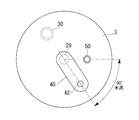
- the reed valve 40 is attached to the discharge cover 3 so that the refrigerant discharged from the discharge port 29 to the discharge chamber 5 is blown out in the direction away from the injection pipe 50.
- the injection pipe 50 is provided on the rear side in the blowing direction of the refrigerant from the discharge port 29, and the refrigerant is blown out in the direction away from the injection pipe 50.
- the refrigerant is blown out in the direction away from the injection pipe 50 by the reed valve 40 provided at the discharge port 29. Therefore, since the high temperature refrigerant discharged from the discharge port 29 does not directly go to the piping portion at the shortest distance, the refrigerant passing through the injection pipe 50 is hardly heated.
- a line connecting one end and the other end of the reed valve 40 which is a plate-like member, the discharge port 29 and the injection pipe 50 The connecting line is desirably less than 90 °, preferably not more than 60 °.
- the injection pipe 50 is provided at the rear side in the blowout direction of the refrigerant from the discharge port 29, and the refrigerant is reliably blown out in the direction away from the injection pipe 50.
- illustration of the retainer 41 is abbreviate
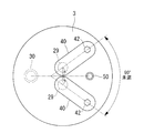
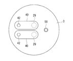
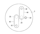
- FIGS. 8 and 9 unlike the case where only one discharge port 29 is formed in the discharge cover 3, a line connecting one end and the other end of the reed valve 40, the discharge port 29 and the injection pipe 50. It is difficult to make the line connecting them less than 90 °. Even if the line connecting one end and the other end of the reed valve 40 and the line connecting the discharge port 29 and the injection pipe 50 can be 90 °, the refrigerant blown out from the discharge port 29 may possibly hit the injection pipe 50 is there.
- 8 shows the case where two reed valves are fixed on the same side with respect to the discharge port 29, and
- FIG. 9 shows the case where two reed valves are fixed on different sides with respect to the discharge port 29. There is.
- the injection pipe 50 is installed on a perpendicular bisector of a line connecting the two discharge ports 29. .
- the two reed valves 40 can be installed so as to sandwich the injection pipe 50, and the refrigerant is blown out in the direction away from the injection pipe 50.
- the angle between the line connecting one end and the other end of one reed valve 40 and the line connecting the one end and the other end of the other reed valve 40 is 90 It is desirable that it is less than or equal to °.
- the refrigerant can be blown out in the direction away from the injection pipe 50 without the refrigerants blown out from the two discharge ports 29 interfering with each other.
- the refrigerant blown out from the discharge port 29 does not directly hit the injection pipe 50, the refrigerant flowing inside the injection pipe 50 is not easily heated.
- the inside of the compression chamber 20 is appropriately cooled by the refrigerant that passes through the injection pipe 50 and is supplied to the compression chamber 20, and the performance degradation of the hermetic scroll compressor 1 can be prevented.
- the discharge pipe 30 is installed such that the refrigerant discharged from the discharge port 29 to the discharge chamber 5 is blown out by the reed valve 40 in the direction approaching the discharge pipe 30. That is, the discharge pipe 30 is provided on the front side in the blowing direction of the refrigerant from the discharge port 29. As a result, the amount of the refrigerant discharged from the discharge port 29 toward the injection pipe 50 decreases, and the refrigerant flowing inside the injection pipe 50 becomes less likely to be heated.
- discharge pipe 30 is provided with injection via a line connecting two discharge ports 29. It is provided on the opposite side to the tube 50.
- the discharge pipe 30 is disposed on a vertical bisector of a line connecting two discharge ports 29.
- the reed valve 40 is installed for the discharge port 29 formed in the discharge cover 3
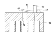
- the present invention is not limited to this example. That is, in the case where the discharge cover 3 is not provided, the reed valve 40 may be installed to the discharge port 24 formed in the fixed scroll 18 as shown in FIG. 5. Also in this case, the reed valve 40 is installed based on the relationship between the blowing direction of the refrigerant blown out from the discharge port 24 regulated by the reed valve 40 and the position of the injection pipe 50 as in the above description.
- the discharge pipe 30 may also be installed in the same manner as described above.
- the refrigerant blown out from the discharge port 24 does not directly hit the injection pipe 50, so the refrigerant flowing inside the injection pipe 50 is It is hard to be heated.
- the inside of the compression chamber 20 can be appropriately cooled by the refrigerant that passes through the injection pipe 50 and is supplied to the compression chamber 20, and the performance degradation of the compressor can be prevented.
Landscapes
- Engineering & Computer Science (AREA)
- Mechanical Engineering (AREA)
- General Engineering & Computer Science (AREA)
- Applications Or Details Of Rotary Compressors (AREA)
- Rotary Pumps (AREA)
Priority Applications (2)
| Application Number | Priority Date | Filing Date | Title |
|---|---|---|---|
| EP17760066.5A EP3382205B1 (de) | 2016-03-04 | 2017-03-01 | Verdichter |
| CN201780005285.XA CN108474378B (zh) | 2016-03-04 | 2017-03-01 | 压缩机 |
Applications Claiming Priority (2)
| Application Number | Priority Date | Filing Date | Title |
|---|---|---|---|
| JP2016-042114 | 2016-03-04 | ||
| JP2016042114A JP6710545B2 (ja) | 2016-03-04 | 2016-03-04 | 圧縮機 |
Publications (1)
| Publication Number | Publication Date |
|---|---|
| WO2017150602A1 true WO2017150602A1 (ja) | 2017-09-08 |
Family
ID=59744113
Family Applications (1)
| Application Number | Title | Priority Date | Filing Date |
|---|---|---|---|
| PCT/JP2017/008085 WO2017150602A1 (ja) | 2016-03-04 | 2017-03-01 | 圧縮機 |
Country Status (4)
| Country | Link |
|---|---|
| EP (1) | EP3382205B1 (de) |
| JP (1) | JP6710545B2 (de) |
| CN (1) | CN108474378B (de) |
| WO (1) | WO2017150602A1 (de) |
Cited By (1)
| Publication number | Priority date | Publication date | Assignee | Title |
|---|---|---|---|---|
| EP3578823A1 (de) * | 2018-06-05 | 2019-12-11 | Mitsubishi Heavy Industries Thermal Systems, Ltd. | Verdichter und verfahren zur herstellung des verdichters |
Families Citing this family (6)
| Publication number | Priority date | Publication date | Assignee | Title |
|---|---|---|---|---|
| JP7154868B2 (ja) * | 2018-08-02 | 2022-10-18 | 三菱重工サーマルシステムズ株式会社 | 圧縮機 |
| KR20210012292A (ko) | 2019-07-24 | 2021-02-03 | 한온시스템 주식회사 | 스크롤 압축기 |
| WO2021111546A1 (ja) * | 2019-12-04 | 2021-06-10 | 三菱電機株式会社 | 圧縮機 |
| KR20210105565A (ko) * | 2020-02-19 | 2021-08-27 | 한온시스템 주식회사 | 스크롤 압축기 |
| US11384759B2 (en) * | 2020-03-10 | 2022-07-12 | Hanon Systems | Vapor injection double reed valve plate |
| CN218542593U (zh) * | 2020-03-27 | 2023-02-28 | 三菱电机株式会社 | 涡旋压缩机 |
Citations (6)
| Publication number | Priority date | Publication date | Assignee | Title |
|---|---|---|---|---|
| JPH0364686A (ja) * | 1989-07-31 | 1991-03-20 | Sanden Corp | スクロール型圧縮機 |
| JPH09158856A (ja) * | 1995-12-05 | 1997-06-17 | Matsushita Electric Ind Co Ltd | スクロール気体圧縮機 |
| US6299417B1 (en) * | 1999-10-04 | 2001-10-09 | Lg Electronics, Inc. | Back pressure structure of intermediate pressure of scroll compressor |
| JP2006348933A (ja) * | 2005-05-17 | 2006-12-28 | Daikin Ind Ltd | 回転式圧縮機 |
| JP2009287512A (ja) * | 2008-05-30 | 2009-12-10 | Mitsubishi Heavy Ind Ltd | 冷媒圧縮機および弁ユニット |
| JP2015098804A (ja) * | 2013-11-18 | 2015-05-28 | 株式会社豊田自動織機 | 電動圧縮機 |
Family Cites Families (4)
| Publication number | Priority date | Publication date | Assignee | Title |
|---|---|---|---|---|
| JPS58187594A (ja) * | 1982-04-28 | 1983-11-01 | Hitachi Ltd | スクロ−ル圧縮機 |
| US5741120A (en) * | 1995-06-07 | 1998-04-21 | Copeland Corporation | Capacity modulated scroll machine |
| MY119499A (en) * | 1995-12-05 | 2005-06-30 | Matsushita Electric Ind Co Ltd | Scroll compressor having bypass valves |
| CN100549424C (zh) * | 2005-05-17 | 2009-10-14 | 大金工业株式会社 | 旋转式压缩机 |
-
2016
- 2016-03-04 JP JP2016042114A patent/JP6710545B2/ja active Active
-
2017
- 2017-03-01 EP EP17760066.5A patent/EP3382205B1/de active Active
- 2017-03-01 WO PCT/JP2017/008085 patent/WO2017150602A1/ja active Application Filing
- 2017-03-01 CN CN201780005285.XA patent/CN108474378B/zh active Active
Patent Citations (6)
| Publication number | Priority date | Publication date | Assignee | Title |
|---|---|---|---|---|
| JPH0364686A (ja) * | 1989-07-31 | 1991-03-20 | Sanden Corp | スクロール型圧縮機 |
| JPH09158856A (ja) * | 1995-12-05 | 1997-06-17 | Matsushita Electric Ind Co Ltd | スクロール気体圧縮機 |
| US6299417B1 (en) * | 1999-10-04 | 2001-10-09 | Lg Electronics, Inc. | Back pressure structure of intermediate pressure of scroll compressor |
| JP2006348933A (ja) * | 2005-05-17 | 2006-12-28 | Daikin Ind Ltd | 回転式圧縮機 |
| JP2009287512A (ja) * | 2008-05-30 | 2009-12-10 | Mitsubishi Heavy Ind Ltd | 冷媒圧縮機および弁ユニット |
| JP2015098804A (ja) * | 2013-11-18 | 2015-05-28 | 株式会社豊田自動織機 | 電動圧縮機 |
Cited By (1)
| Publication number | Priority date | Publication date | Assignee | Title |
|---|---|---|---|---|
| EP3578823A1 (de) * | 2018-06-05 | 2019-12-11 | Mitsubishi Heavy Industries Thermal Systems, Ltd. | Verdichter und verfahren zur herstellung des verdichters |
Also Published As
| Publication number | Publication date |
|---|---|
| JP2017155719A (ja) | 2017-09-07 |
| CN108474378A (zh) | 2018-08-31 |
| EP3382205A4 (de) | 2018-11-07 |
| CN108474378B (zh) | 2020-10-27 |
| JP6710545B2 (ja) | 2020-06-17 |
| EP3382205A1 (de) | 2018-10-03 |
| EP3382205B1 (de) | 2020-11-18 |
Similar Documents
| Publication | Publication Date | Title |
|---|---|---|
| WO2017150602A1 (ja) | 圧縮機 | |
| US8998596B2 (en) | Scroll compressor | |
| KR102408562B1 (ko) | 스크롤 압축기 | |
| US11566620B2 (en) | Motor driven compressor apparatus including swing pin | |
| US8690555B2 (en) | Two-stage rotary expander, expander-compressor unit, and refrigeration cycle apparatus | |
| US7588428B2 (en) | Rotary fluid device performing compression and expansion of fluid within a common cylinder | |
| JP2010053798A (ja) | スクロール圧縮機 | |
| JP5515289B2 (ja) | 冷凍装置 | |
| JP4696530B2 (ja) | 流体機械 | |
| JP4930314B2 (ja) | 容積型膨張機、膨張機一体型圧縮機、および冷凍サイクル装置 | |
| JP4682795B2 (ja) | 膨張機一体型圧縮機及び冷凍サイクル装置 | |
| KR100557061B1 (ko) | 스크롤 압축기 | |
| KR102392491B1 (ko) | 스크롤형 압축기 | |
| JP5209279B2 (ja) | スクロール圧縮機 | |
| JP2008267345A (ja) | 電動圧縮機 | |
| JP2017172346A (ja) | スクロール圧縮機、及び、空気調和機 | |
| AU2007237797A1 (en) | Fluid machine | |
| WO2022264792A1 (ja) | スクロール圧縮機 | |
| JP3574904B2 (ja) | 密閉式容積形圧縮機 | |
| CN114222861B (zh) | 涡旋压缩机 | |
| JP2006132332A (ja) | 流体機械 | |
| JP4879078B2 (ja) | 圧縮機 | |
| JP2018031292A (ja) | スクロール圧縮機 | |
| JP2008002422A (ja) | スクロール圧縮機 | |
| WO2021038738A1 (ja) | スクロール圧縮機 |
Legal Events
| Date | Code | Title | Description |
|---|---|---|---|
| WWE | Wipo information: entry into national phase |
Ref document number: 2017760066 Country of ref document: EP |
|
| ENP | Entry into the national phase |
Ref document number: 2017760066 Country of ref document: EP Effective date: 20180629 |
|
| NENP | Non-entry into the national phase |
Ref country code: DE |