WO2017150602A1 - Compressor - Google Patents
Compressor Download PDFInfo
- Publication number
- WO2017150602A1 WO2017150602A1 PCT/JP2017/008085 JP2017008085W WO2017150602A1 WO 2017150602 A1 WO2017150602 A1 WO 2017150602A1 JP 2017008085 W JP2017008085 W JP 2017008085W WO 2017150602 A1 WO2017150602 A1 WO 2017150602A1
- Authority
- WO
- WIPO (PCT)
- Prior art keywords
- discharge
- refrigerant
- discharge port
- reed valve
- pipe
- Prior art date
Links
Images


Classifications
-
- F—MECHANICAL ENGINEERING; LIGHTING; HEATING; WEAPONS; BLASTING
- F04—POSITIVE - DISPLACEMENT MACHINES FOR LIQUIDS; PUMPS FOR LIQUIDS OR ELASTIC FLUIDS
- F04C—ROTARY-PISTON, OR OSCILLATING-PISTON, POSITIVE-DISPLACEMENT MACHINES FOR LIQUIDS; ROTARY-PISTON, OR OSCILLATING-PISTON, POSITIVE-DISPLACEMENT PUMPS
- F04C18/00—Rotary-piston pumps specially adapted for elastic fluids
- F04C18/02—Rotary-piston pumps specially adapted for elastic fluids of arcuate-engagement type, i.e. with circular translatory movement of co-operating members, each member having the same number of teeth or tooth-equivalents
-
- F—MECHANICAL ENGINEERING; LIGHTING; HEATING; WEAPONS; BLASTING
- F04—POSITIVE - DISPLACEMENT MACHINES FOR LIQUIDS; PUMPS FOR LIQUIDS OR ELASTIC FLUIDS
- F04C—ROTARY-PISTON, OR OSCILLATING-PISTON, POSITIVE-DISPLACEMENT MACHINES FOR LIQUIDS; ROTARY-PISTON, OR OSCILLATING-PISTON, POSITIVE-DISPLACEMENT PUMPS
- F04C23/00—Combinations of two or more pumps, each being of rotary-piston or oscillating-piston type, specially adapted for elastic fluids; Pumping installations specially adapted for elastic fluids; Multi-stage pumps specially adapted for elastic fluids
- F04C23/008—Hermetic pumps
-
- F—MECHANICAL ENGINEERING; LIGHTING; HEATING; WEAPONS; BLASTING
- F04—POSITIVE - DISPLACEMENT MACHINES FOR LIQUIDS; PUMPS FOR LIQUIDS OR ELASTIC FLUIDS
- F04C—ROTARY-PISTON, OR OSCILLATING-PISTON, POSITIVE-DISPLACEMENT MACHINES FOR LIQUIDS; ROTARY-PISTON, OR OSCILLATING-PISTON, POSITIVE-DISPLACEMENT PUMPS
- F04C18/00—Rotary-piston pumps specially adapted for elastic fluids
- F04C18/02—Rotary-piston pumps specially adapted for elastic fluids of arcuate-engagement type, i.e. with circular translatory movement of co-operating members, each member having the same number of teeth or tooth-equivalents
- F04C18/0207—Rotary-piston pumps specially adapted for elastic fluids of arcuate-engagement type, i.e. with circular translatory movement of co-operating members, each member having the same number of teeth or tooth-equivalents both members having co-operating elements in spiral form
- F04C18/0215—Rotary-piston pumps specially adapted for elastic fluids of arcuate-engagement type, i.e. with circular translatory movement of co-operating members, each member having the same number of teeth or tooth-equivalents both members having co-operating elements in spiral form where only one member is moving
-
- F—MECHANICAL ENGINEERING; LIGHTING; HEATING; WEAPONS; BLASTING
- F04—POSITIVE - DISPLACEMENT MACHINES FOR LIQUIDS; PUMPS FOR LIQUIDS OR ELASTIC FLUIDS
- F04C—ROTARY-PISTON, OR OSCILLATING-PISTON, POSITIVE-DISPLACEMENT MACHINES FOR LIQUIDS; ROTARY-PISTON, OR OSCILLATING-PISTON, POSITIVE-DISPLACEMENT PUMPS
- F04C29/00—Component parts, details or accessories of pumps or pumping installations, not provided for in groups F04C18/00 - F04C28/00
- F04C29/04—Heating; Cooling; Heat insulation
- F04C29/042—Heating; Cooling; Heat insulation by injecting a fluid
-
- F—MECHANICAL ENGINEERING; LIGHTING; HEATING; WEAPONS; BLASTING
- F04—POSITIVE - DISPLACEMENT MACHINES FOR LIQUIDS; PUMPS FOR LIQUIDS OR ELASTIC FLUIDS
- F04C—ROTARY-PISTON, OR OSCILLATING-PISTON, POSITIVE-DISPLACEMENT MACHINES FOR LIQUIDS; ROTARY-PISTON, OR OSCILLATING-PISTON, POSITIVE-DISPLACEMENT PUMPS
- F04C29/00—Component parts, details or accessories of pumps or pumping installations, not provided for in groups F04C18/00 - F04C28/00
- F04C29/12—Arrangements for admission or discharge of the working fluid, e.g. constructional features of the inlet or outlet
- F04C29/124—Arrangements for admission or discharge of the working fluid, e.g. constructional features of the inlet or outlet with inlet and outlet valves specially adapted for rotary or oscillating piston pumps
- F04C29/126—Arrangements for admission or discharge of the working fluid, e.g. constructional features of the inlet or outlet with inlet and outlet valves specially adapted for rotary or oscillating piston pumps of the non-return type
- F04C29/128—Arrangements for admission or discharge of the working fluid, e.g. constructional features of the inlet or outlet with inlet and outlet valves specially adapted for rotary or oscillating piston pumps of the non-return type of the elastic type, e.g. reed valves
-
- F—MECHANICAL ENGINEERING; LIGHTING; HEATING; WEAPONS; BLASTING
- F04—POSITIVE - DISPLACEMENT MACHINES FOR LIQUIDS; PUMPS FOR LIQUIDS OR ELASTIC FLUIDS
- F04C—ROTARY-PISTON, OR OSCILLATING-PISTON, POSITIVE-DISPLACEMENT MACHINES FOR LIQUIDS; ROTARY-PISTON, OR OSCILLATING-PISTON, POSITIVE-DISPLACEMENT PUMPS
- F04C2240/00—Components
- F04C2240/80—Other components
- F04C2240/806—Pipes for fluids; Fittings therefor
Definitions
- the present invention relates to a compressor.
- the closed scroll compressor is used, for example, in a refrigeration system, an air conditioner, etc., and compresses and discharges a refrigerant supplied from the outside.
- a discharge chamber is formed above the scroll compression mechanism in a closed housing.
- the discharge chamber is a space surrounded by the scroll type compression mechanism and the housing, and the refrigerant compressed by the compression mechanism is supplied to temporarily store the refrigerant, and then discharge the refrigerant from the discharge pipe to the outside.
- Patent Documents 1 and 2 listed below disclose that, in a scroll compressor, an injection pipe for introducing a refrigerant at an intermediate pressure from the outside into the compression chamber of the compression mechanism is provided. By supplying the liquid refrigerant to the compression chamber through the injection pipe, the temperature of the refrigerant is reduced by the latent heat when the liquid refrigerant evaporates, and the inside of the compression chamber is cooled.
- a volume control pipe (hereinafter referred to as a "bypass pipe”) may be provided to extract the refrigerant at an intermediate pressure of the compression chamber to the outside.
- the medium pressure refrigerant extracted to the outside is returned to the suction side of the compressor. This enables capacity control operation of the compressor.
- An injection pipe and a bypass pipe provided in the hermetic scroll compressor are provided through the upper portion of the housing and the discharge chamber, and are connected to the compression mechanism. Therefore, the refrigerant passing through the injection pipe and the bypass pipe is heated by the high temperature refrigerant in the discharge chamber.
- the refrigerant discharged from the discharge port 29 is installed toward the injection pipe 50 or the bypass pipe by the reed valve 40, the injection pipe 50 or the bypass pipe The passing refrigerant is likely to be heated.
- the present invention has been made in view of such circumstances, and it is possible to suppress the temperature rise of the refrigerant passing through a pipe section such as an injection pipe and a bypass pipe installed inside the discharge chamber.
- the purpose is to provide a machine.
- a compressor of the present invention adopts the following means. That is, the compressor according to one aspect of the present invention includes a housing, a scroll-type compression mechanism housed in the housing, and a discharge cover or the discharge cover provided with a discharge port through which the refrigerant compressed by the compression mechanism passes.
- a fixed scroll of a compression mechanism a discharge chamber formed between the housing and the discharge cover or the fixed scroll, a piping portion which passes through the discharge chamber and through which the refrigerant flows; And a reed valve provided at the discharge port of the discharge cover or the fixed scroll and having a configuration in which the refrigerant discharged from the discharge port to the discharge chamber is blown out in a direction away from the piping portion.
- the refrigerant compressed by the compression mechanism is formed between the housing and the discharge cover or between the housing and the fixed scroll of the compression mechanism from the discharge port provided in the discharge cover or the fixed scroll of the compression mechanism. It is discharged into the discharge chamber. At this time, the refrigerant discharged from the discharge port to the discharge chamber is blown out in the direction away from the piping portion by the reed valve provided at the discharge port. Therefore, since the high temperature refrigerant discharged from the discharge port does not directly go to the piping part at the shortest distance, the refrigerant passing through the piping part is not easily heated.
- the reed valve may have a plate-like member that blows out the refrigerant discharged from the discharge port in a predetermined blowing direction, and the piping portion may be provided on the rear side in the blowing direction.
- the refrigerant discharged from the discharge port is blown out in the predetermined blowing direction by the plate-like member of the reed valve. Then, since the piping portion is provided on the rear side in the predetermined blowing direction of the refrigerant, the refrigerant discharged from the discharge port to the discharge chamber does not directly go to the piping portion, so the refrigerant passing through the piping portion is heated Hateful.
- the plate-like member of the reed valve is long in one direction, one end thereof is fixed to the discharge cover or the fixed scroll, and the other end can be opened and closed with respect to the discharge port.
- the line connecting the one end and the other end and the line connecting the discharge port and the piping portion may be 90 ° or less.
- the plate-like member of the reed valve is long in one direction, one end is fixed to the discharge cover or the fixed scroll, the other end can be opened and closed with respect to the discharge port, and the discharge port is
- the reed valve is provided at two places, one at each of the discharge ports, the plate-like members of the two reed valves may be installed so as to sandwich the pipe portion.
- the above-mentioned piping part may be installed on a perpendicular bisector of a line segment which connects two above-mentioned discharge mouths.
- the angle formed by the line connecting the one end and the other end of one plate member and the line connecting the one end and the other end of the other plate member may be 90 ° or less.
- the discharge valve further includes a discharge pipe installed through the housing and discharging the refrigerant in the discharge chamber to the outside, and the refrigerant discharged from the discharge port to the discharge chamber is discharged by the reed valve.
- the discharge pipe may be installed so as to blow out in a direction approaching the pipe.
- the discharge valve further includes a discharge pipe installed through the housing and discharging the refrigerant in the discharge chamber to the outside, and the refrigerant discharged from the discharge port to the discharge chamber is discharged by the reed valve.
- the discharge pipe is installed so as to be blown out in a direction approaching the pipe, and the discharge pipe is installed on the opposite side of the piping section with a line connecting the two discharge ports interposed therebetween. It is also good.
- the present invention it is possible to suppress the temperature rise of the refrigerant passing through the piping portion such as the injection pipe and the bypass pipe, which is installed inside the discharge chamber.
- a hermetic scroll compressor 1 as a scroll fluid machine includes a vertically elongated cylindrical hermetic housing 2 whose bottom is sealed by a lower cover.
- the upper portion of the sealed housing 2 is sealed by a discharge cover 3 and an upper cover 4, and a discharge chamber 5 is formed between the discharge cover 3 and the upper cover 4 for discharging a compressed high-pressure gas. .
- An upper bearing member (frame member) 6 is fixedly installed at the upper portion in the sealed housing 2, and the scroll compression mechanism 7 is incorporated via the upper bearing member 6, and the stator 8 and the rotor 9 are formed at the lower portion.
- An electric motor 10 is provided. The electric motor 10 is incorporated by the stator 8 being fixedly installed in the closed housing 2, and the crankshaft 11 is fixed to the rotor 9.
- crank pin 12 whose axis is eccentric by a predetermined dimension is provided, and the scroll compression mechanism 7 is driven by the electric motor 10 by connecting the crank pin 12 to the scroll compression mechanism 7. It is made possible.
- the upper portion of the crankshaft 11 is rotatably supported by the journal bearing portion 6A of the upper bearing member 6, and the lower end portion is rotatably supported by the lower journal bearing 13 provided at the lower portion of the sealed housing 2. ing.
- a positive displacement oil supply pump 14 is provided, and the lubricating oil 15 filled in the bottom of the sealed housing 2 is sucked through the suction pipe 16 It is configured to discharge into a flow passage 17 which is bored in the shaft 11 along the axial direction.
- the lubricating oil 15 can be supplied to a portion requiring lubrication such as the upper bearing member 6, the scroll compression mechanism 7 and the lower journal bearing 13 through the flow passage 17.
- the scroll compression mechanism 7 has the upper bearing member 6 as one component, and is slidably supported by the fixed scroll 18 fixedly installed on the upper bearing member 6 and the thrust bearing portion 6B of the upper bearing member 6 Is interposed between the upper bearing member 6 and the orbiting scroll 19 so as to prevent rotation of the orbiting scroll 19 and to rotate the orbiting orbit.
- the rotational force of the crankshaft 11 is provided to the orbiting scroll 19 provided between the rotation preventing mechanism 21 such as an acceptable Oldham ring, and the bearing boss 19C provided on the crank pin 12 of the crankshaft 11 and the back surface of the orbiting scroll 19.
- the fixed scroll 18 is provided with a drive bush 22 and a pivot bearing (needle bearing) 23 for It is installed on the upper bearing member 6 in a state connected to the scan charge cover 3.
- the fixed scroll 18 includes an end plate 18A and a spiral wrap 18B erected on the end plate 18A.
- a discharge port 24 is provided at the center of the end plate 18A, and wrap teeth of the spiral wrap 18B are provided.
- the tip seal 25 is installed on the front surface.
- the orbiting scroll 19 also includes an end plate 19A and a spiral wrap 19B erected on the end plate 19A.
- a bearing boss 19C is provided on the back of the end plate 19A, and the wrap of the spiral wrap 19B is provided.
- the tip seal 26 is installed on the tooth tip surface.
- the scroll compression mechanism 7 opens the refrigerant gas sucked into the sealed housing 2 through the suction pipe 27 opened at a position facing the stator winding 8A of the electric motor 10 into the sealed housing 2. It is drawn into the compression chamber 20 from the suction port 28 and compressed into a high temperature and high pressure gas. The compressed gas is discharged into the discharge chamber 5 through the discharge port 24 provided at the center of the fixed scroll 18 and the discharge port 29 provided to the discharge cover 3, and is further connected to the discharge chamber 5. It is sent to the outside of the compressor through the discharge pipe 30 which
- an injection pipe 50 for introducing a refrigerant at an intermediate pressure into the compression chamber 20 of the scroll compression mechanism 7 from the outside is provided.
- the temperature of the refrigerant can be lowered by the latent heat when the liquid refrigerant evaporates, and the inside of the compression chamber 20 can be cooled.
- the injection pipe penetrates the closed housing 2 and the discharge chamber 5 and is connected to the fixed scroll 18.
- the reed valve 40 is a thin plate member and is provided at the outlet of the discharge port 29 to open and close the discharge port 29.
- the reed valve 40 regulates the flow of the refrigerant in only one direction. By providing the reed valve 40, in the present embodiment, the refrigerant flows only from the compression chamber 20 to the discharge chamber 5 side.
- a retainer 41 for limiting the movable range (the upper limit of the opening degree) of the reed valve 40 is provided above the reed valve 40.
- the reed valve 40 opens, the reed valve 40 contacts the lower surface of the retainer 41, whereby the retainer 41 can be regulated so that the reed valve 40 does not open too much.
- the retainer 41 is a highly rigid member that is unlikely to be deformed.
- the reed valve 40 is a member which is long in one direction, and its end has, for example, an arc shape. One end side of the reed valve 40 is fixed to the discharge cover 3 by a bolt 42, and the other end side of the reed valve 40 can be opened and closed with respect to the discharge port 29.
- the retainer 41 is a member which is long in one direction, and one end side thereof is fixed together with the reed valve 40 by a bolt 42 on the upper side of the reed valve 40.
- the reed valve 40 blows out the refrigerant discharged from the discharge port 29 in a predetermined blowing direction.
- the predetermined blowing direction is the front of the center of the circle of the discharge port 29 having a circular shape, assuming that the movable side opposite to the side fixed by the bolt 42 is the front.
- the refrigerant flowing to the rear side with respect to the center of the discharge port 29 is also smaller than the amount flowing to the front.
- the reed valve 40 is attached to the discharge cover 3 so that the refrigerant discharged from the discharge port 29 to the discharge chamber 5 is blown out in the direction away from the injection pipe 50.
- the injection pipe 50 is provided on the rear side in the blowing direction of the refrigerant from the discharge port 29, and the refrigerant is blown out in the direction away from the injection pipe 50.
- the refrigerant is blown out in the direction away from the injection pipe 50 by the reed valve 40 provided at the discharge port 29. Therefore, since the high temperature refrigerant discharged from the discharge port 29 does not directly go to the piping portion at the shortest distance, the refrigerant passing through the injection pipe 50 is hardly heated.
- a line connecting one end and the other end of the reed valve 40 which is a plate-like member, the discharge port 29 and the injection pipe 50 The connecting line is desirably less than 90 °, preferably not more than 60 °.
- the injection pipe 50 is provided at the rear side in the blowout direction of the refrigerant from the discharge port 29, and the refrigerant is reliably blown out in the direction away from the injection pipe 50.
- illustration of the retainer 41 is abbreviate
- FIGS. 8 and 9 unlike the case where only one discharge port 29 is formed in the discharge cover 3, a line connecting one end and the other end of the reed valve 40, the discharge port 29 and the injection pipe 50. It is difficult to make the line connecting them less than 90 °. Even if the line connecting one end and the other end of the reed valve 40 and the line connecting the discharge port 29 and the injection pipe 50 can be 90 °, the refrigerant blown out from the discharge port 29 may possibly hit the injection pipe 50 is there.
- 8 shows the case where two reed valves are fixed on the same side with respect to the discharge port 29, and
- FIG. 9 shows the case where two reed valves are fixed on different sides with respect to the discharge port 29. There is.
- the injection pipe 50 is installed on a perpendicular bisector of a line connecting the two discharge ports 29. .
- the two reed valves 40 can be installed so as to sandwich the injection pipe 50, and the refrigerant is blown out in the direction away from the injection pipe 50.
- the angle between the line connecting one end and the other end of one reed valve 40 and the line connecting the one end and the other end of the other reed valve 40 is 90 It is desirable that it is less than or equal to °.
- the refrigerant can be blown out in the direction away from the injection pipe 50 without the refrigerants blown out from the two discharge ports 29 interfering with each other.
- the refrigerant blown out from the discharge port 29 does not directly hit the injection pipe 50, the refrigerant flowing inside the injection pipe 50 is not easily heated.
- the inside of the compression chamber 20 is appropriately cooled by the refrigerant that passes through the injection pipe 50 and is supplied to the compression chamber 20, and the performance degradation of the hermetic scroll compressor 1 can be prevented.
- the discharge pipe 30 is installed such that the refrigerant discharged from the discharge port 29 to the discharge chamber 5 is blown out by the reed valve 40 in the direction approaching the discharge pipe 30. That is, the discharge pipe 30 is provided on the front side in the blowing direction of the refrigerant from the discharge port 29. As a result, the amount of the refrigerant discharged from the discharge port 29 toward the injection pipe 50 decreases, and the refrigerant flowing inside the injection pipe 50 becomes less likely to be heated.
- discharge pipe 30 is provided with injection via a line connecting two discharge ports 29. It is provided on the opposite side to the tube 50.
- the discharge pipe 30 is disposed on a vertical bisector of a line connecting two discharge ports 29.
- the reed valve 40 is installed for the discharge port 29 formed in the discharge cover 3
- the present invention is not limited to this example. That is, in the case where the discharge cover 3 is not provided, the reed valve 40 may be installed to the discharge port 24 formed in the fixed scroll 18 as shown in FIG. 5. Also in this case, the reed valve 40 is installed based on the relationship between the blowing direction of the refrigerant blown out from the discharge port 24 regulated by the reed valve 40 and the position of the injection pipe 50 as in the above description.
- the discharge pipe 30 may also be installed in the same manner as described above.
- the refrigerant blown out from the discharge port 24 does not directly hit the injection pipe 50, so the refrigerant flowing inside the injection pipe 50 is It is hard to be heated.
- the inside of the compression chamber 20 can be appropriately cooled by the refrigerant that passes through the injection pipe 50 and is supplied to the compression chamber 20, and the performance degradation of the compressor can be prevented.
Abstract
This hermetic scroll compressor comprises: a hermetic housing; a scroll compressing mechanism housed in the hermetic housing; a discharge cover (3) provided with a discharge port (29) through which a refrigerant compressed by the scroll compressing mechanism passes; a discharge chamber formed between the hermetic housing and the discharge cover (3); an injection tube (50) provided so as to be passed inside the discharge chamber, and within which the refrigerant flows; and a reed valve (40) that is provided to the discharge port (29) of the discharge cover (3), and that is configured such that the refrigerant discharged from the discharge port (29) to the discharge chamber is ejected in a direction separating from the injection tube (50).
Description
本発明は、圧縮機に関するものである。
The present invention relates to a compressor.
密閉型スクロール圧縮機は、例えば冷凍装置、空気調和装置などに用いられ、外部から供給された冷媒を圧縮して吐出する。
密閉型スクロール圧縮機は、密閉されたハウジングにおいて、スクロール型圧縮機構の上部に吐出チャンバーが形成されている。吐出チャンバーは、スクロール型圧縮機構とハウジングに囲まれた空間であり、圧縮機構で圧縮された冷媒が供給されて、冷媒を一時的に貯留し、その後、吐出管から外部へ冷媒を吐出させる。 The closed scroll compressor is used, for example, in a refrigeration system, an air conditioner, etc., and compresses and discharges a refrigerant supplied from the outside.
In the closed scroll compressor, a discharge chamber is formed above the scroll compression mechanism in a closed housing. The discharge chamber is a space surrounded by the scroll type compression mechanism and the housing, and the refrigerant compressed by the compression mechanism is supplied to temporarily store the refrigerant, and then discharge the refrigerant from the discharge pipe to the outside.
下記の特許文献1及び2では、スクロール型圧縮機において、外部から圧縮機構の圧縮室の内部へ中間圧の冷媒を導入するインジェクション管が設けられることが記載されている。インジェクション管を介して液冷媒を圧縮室へ供給することによって、液冷媒が蒸発する際の潜熱によって冷媒の温度を低下させ、圧縮室の内部を冷却する。
Patent Documents 1 and 2 listed below disclose that, in a scroll compressor, an injection pipe for introducing a refrigerant at an intermediate pressure from the outside into the compression chamber of the compression mechanism is provided. By supplying the liquid refrigerant to the compression chamber through the injection pipe, the temperature of the refrigerant is reduced by the latent heat when the liquid refrigerant evaporates, and the inside of the compression chamber is cooled.
また、スクロール型圧縮機において、圧縮室の中間圧の冷媒を外部へ抽出する容量制御管(以下「バイパス管」という。)が設けられる場合がある。外部へ抽出された中間圧の冷媒は、圧縮機の吸入側へ戻される。これにより、圧縮機の容量制御運転が可能になる。
In addition, in the scroll compressor, a volume control pipe (hereinafter referred to as a "bypass pipe") may be provided to extract the refrigerant at an intermediate pressure of the compression chamber to the outside. The medium pressure refrigerant extracted to the outside is returned to the suction side of the compressor. This enables capacity control operation of the compressor.
密閉型スクロール圧縮機に設けられるインジェクション管やバイパス管は、ハウジングの上部及び吐出チャンバーを貫通して設けられ、圧縮機構と接続される。そのため、インジェクション管やバイパス管を通過する冷媒は、吐出チャンバー内の高温の冷媒によって加熱されてしまう。特に、図6及び図7に示すように、吐出ポート29から吐出された冷媒が、リード弁40によってインジェクション管50又はバイパス管のほうへ向かうように設置されると、インジェクション管50やバイパス管を通過する冷媒が加熱されやすい。インジェクション管を通過する冷媒が加熱されると、圧縮室の内部を冷却できないという問題が生じ、また、バイパス管を通過する冷媒が加熱されると、冷媒の体積が増えて圧縮効率が低下するという問題が生じ、いずれの場合も圧縮機の所望の性能が得られない。
An injection pipe and a bypass pipe provided in the hermetic scroll compressor are provided through the upper portion of the housing and the discharge chamber, and are connected to the compression mechanism. Therefore, the refrigerant passing through the injection pipe and the bypass pipe is heated by the high temperature refrigerant in the discharge chamber. In particular, as shown in FIG. 6 and FIG. 7, when the refrigerant discharged from the discharge port 29 is installed toward the injection pipe 50 or the bypass pipe by the reed valve 40, the injection pipe 50 or the bypass pipe The passing refrigerant is likely to be heated. When the refrigerant passing through the injection pipe is heated, there arises a problem that the inside of the compression chamber can not be cooled, and when the refrigerant passing through the bypass pipe is heated, the volume of the refrigerant increases and the compression efficiency decreases. Problems arise and in each case the desired performance of the compressor is not obtained.
本発明は、このような事情に鑑みてなされたものであって、吐出チャンバー内部に設置された、インジェクション管やバイパス管などの配管部を通過する冷媒の温度上昇を抑制することが可能な圧縮機を提供することを目的とする。
The present invention has been made in view of such circumstances, and it is possible to suppress the temperature rise of the refrigerant passing through a pipe section such as an injection pipe and a bypass pipe installed inside the discharge chamber. The purpose is to provide a machine.
上記課題を解決するために、本発明の圧縮機は以下の手段を採用する。
すなわち、本発明の一態様に係る圧縮機は、ハウジングと、前記ハウジングに収容されたスクロール型の圧縮機構と、前記圧縮機構で圧縮された冷媒が通過する吐出口が設けられたディスチャージカバー又は前記圧縮機構の固定スクロールと、前記ハウジングと前記ディスチャージカバー又は前記固定スクロールとの間に形成された吐出チャンバーと、前記吐出チャンバー内を通過して設けられ、内部を冷媒が流通する配管部と、前記ディスチャージカバー又は前記固定スクロールの前記吐出口に設けられ、前記吐出口から前記吐出チャンバーへ吐出される冷媒が、前記配管部から離れる方向に吹き出される構成を有しているリード弁とを備える。 In order to solve the above-mentioned subject, a compressor of the present invention adopts the following means.
That is, the compressor according to one aspect of the present invention includes a housing, a scroll-type compression mechanism housed in the housing, and a discharge cover or the discharge cover provided with a discharge port through which the refrigerant compressed by the compression mechanism passes. A fixed scroll of a compression mechanism, a discharge chamber formed between the housing and the discharge cover or the fixed scroll, a piping portion which passes through the discharge chamber and through which the refrigerant flows; And a reed valve provided at the discharge port of the discharge cover or the fixed scroll and having a configuration in which the refrigerant discharged from the discharge port to the discharge chamber is blown out in a direction away from the piping portion.
この構成によれば、圧縮機構で圧縮された冷媒は、ディスチャージカバー又は圧縮機構の固定スクロールに設けられた吐出口から、ハウジングとディスチャージカバーの間又はハウジングと圧縮機構の固定スクロールの間に形成された吐出チャンバーへ吐出される。このとき、吐出口から吐出チャンバーへ吐出される冷媒は、吐出口に設けられたリード弁によって、配管部から離れる方向に吹き出される。したがって、吐出口から吐出された高温の冷媒が、最短距離で配管部へ直接向かわないため、配管部を通過する冷媒が加熱されにくい。
According to this configuration, the refrigerant compressed by the compression mechanism is formed between the housing and the discharge cover or between the housing and the fixed scroll of the compression mechanism from the discharge port provided in the discharge cover or the fixed scroll of the compression mechanism. It is discharged into the discharge chamber. At this time, the refrigerant discharged from the discharge port to the discharge chamber is blown out in the direction away from the piping portion by the reed valve provided at the discharge port. Therefore, since the high temperature refrigerant discharged from the discharge port does not directly go to the piping part at the shortest distance, the refrigerant passing through the piping part is not easily heated.
上記態様において、前記リード弁は、前記吐出口から吐出される冷媒を所定の吹き出し方向に吹き出させる板状部材を有し、前記配管部は、前記吹き出し方向の後方側に設けられてもよい。
In the above aspect, the reed valve may have a plate-like member that blows out the refrigerant discharged from the discharge port in a predetermined blowing direction, and the piping portion may be provided on the rear side in the blowing direction.
この構成によれば、リード弁の板状部材によって、吐出口から吐出される冷媒が、所定の吹き出し方向に吹き出される。そして、配管部は、冷媒の所定の吹き出し方向の後方側に設けられることから、吐出口から吐出チャンバーへ吐出される冷媒は、配管部へ直接向かわないため、配管部を通過する冷媒が加熱されにくい。
According to this configuration, the refrigerant discharged from the discharge port is blown out in the predetermined blowing direction by the plate-like member of the reed valve. Then, since the piping portion is provided on the rear side in the predetermined blowing direction of the refrigerant, the refrigerant discharged from the discharge port to the discharge chamber does not directly go to the piping portion, so the refrigerant passing through the piping portion is heated Hateful.
上記態様において、前記リード弁の前記板状部材は、一方向に長く、一端側が前記ディスチャージカバー又は前記固定スクロールに固定され、他端側が前記吐出口に対して開閉可能であり、前記板状部材の前記一端と前記他端を結ぶ線と、前記吐出口と前記配管部とを結ぶ線とは、90°以下でもよい。
In the above aspect, the plate-like member of the reed valve is long in one direction, one end thereof is fixed to the discharge cover or the fixed scroll, and the other end can be opened and closed with respect to the discharge port. The line connecting the one end and the other end and the line connecting the discharge port and the piping portion may be 90 ° or less.
上記態様において、前記リード弁の前記板状部材は、一方向に長く、一端側が前記ディスチャージカバー又は前記固定スクロールに固定され、他端側が前記吐出口に対して開閉可能であり、前記吐出口が2箇所設けられ、各前記吐出口に一つずつ前記リード弁が設けられるとき、二つの前記リード弁の前記板状部材は、前記配管部を挟むように設置されてもよい。
In the above aspect, the plate-like member of the reed valve is long in one direction, one end is fixed to the discharge cover or the fixed scroll, the other end can be opened and closed with respect to the discharge port, and the discharge port is When the reed valve is provided at two places, one at each of the discharge ports, the plate-like members of the two reed valves may be installed so as to sandwich the pipe portion.
上記態様において、二つの前記吐出口を結ぶ線分の垂直二等分線上に、前記配管部が設置されてもよい。
In the above-mentioned mode, the above-mentioned piping part may be installed on a perpendicular bisector of a line segment which connects two above-mentioned discharge mouths.
上記態様において、一方の前記板状部材の前記一端と前記他端を結ぶ線と、他方の前記板状部材の前記一端と前記他端を結ぶ線とのなす角が、90°以下でもよい。
In the above aspect, the angle formed by the line connecting the one end and the other end of one plate member and the line connecting the one end and the other end of the other plate member may be 90 ° or less.
上記態様において、前記ハウジングを貫通して設置され、前記吐出チャンバー内の冷媒を外部へ吐出する吐出管を更に備え、前記吐出口から前記吐出チャンバーへ吐出される冷媒が、前記リード弁によって前記吐出管へ近づく方向に吹き出されるように、前記吐出管が設置されてもよい。
In the above aspect, the discharge valve further includes a discharge pipe installed through the housing and discharging the refrigerant in the discharge chamber to the outside, and the refrigerant discharged from the discharge port to the discharge chamber is discharged by the reed valve. The discharge pipe may be installed so as to blow out in a direction approaching the pipe.
上記態様において、前記ハウジングを貫通して設置され、前記吐出チャンバー内の冷媒を外部へ吐出する吐出管を更に備え、前記吐出口から前記吐出チャンバーへ吐出される冷媒が、前記リード弁によって前記吐出管へ近づく方向に吹き出されるように、前記吐出管が設置され、かつ、前記吐出管は、二つの前記吐出口を結ぶ線を間に挟んで、前記配管部とは反対側に設置されてもよい。
In the above aspect, the discharge valve further includes a discharge pipe installed through the housing and discharging the refrigerant in the discharge chamber to the outside, and the refrigerant discharged from the discharge port to the discharge chamber is discharged by the reed valve. The discharge pipe is installed so as to be blown out in a direction approaching the pipe, and the discharge pipe is installed on the opposite side of the piping section with a line connecting the two discharge ports interposed therebetween. It is also good.
本発明によれば、吐出チャンバー内部に設置された、インジェクション管やバイパス管などの配管部を通過する冷媒の温度上昇を抑制することができる。
According to the present invention, it is possible to suppress the temperature rise of the refrigerant passing through the piping portion such as the injection pipe and the bypass pipe, which is installed inside the discharge chamber.
以下に、本発明の一実施形態に係る密閉型スクロール圧縮機について、図面を参照して説明する。
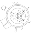
図1に示すように、スクロール流体機械としての密閉型スクロール圧縮機1は、底部が下部カバーによって密閉された上下方向に長い円筒状の密閉ハウジング2を備えている。この密閉ハウジング2の上部は、ディスチャージカバー3及び上部カバー4により密閉されており、このディスチャージカバー3と上部カバー4間に、圧縮された高圧のガスが吐出される吐出チャンバー5が形成されている。 Hereinafter, a sealed scroll compressor according to an embodiment of the present invention will be described with reference to the drawings.
As shown in FIG. 1, a hermetic scroll compressor 1 as a scroll fluid machine includes a vertically elongated cylindricalhermetic housing 2 whose bottom is sealed by a lower cover. The upper portion of the sealed housing 2 is sealed by a discharge cover 3 and an upper cover 4, and a discharge chamber 5 is formed between the discharge cover 3 and the upper cover 4 for discharging a compressed high-pressure gas. .
図1に示すように、スクロール流体機械としての密閉型スクロール圧縮機1は、底部が下部カバーによって密閉された上下方向に長い円筒状の密閉ハウジング2を備えている。この密閉ハウジング2の上部は、ディスチャージカバー3及び上部カバー4により密閉されており、このディスチャージカバー3と上部カバー4間に、圧縮された高圧のガスが吐出される吐出チャンバー5が形成されている。 Hereinafter, a sealed scroll compressor according to an embodiment of the present invention will be described with reference to the drawings.
As shown in FIG. 1, a hermetic scroll compressor 1 as a scroll fluid machine includes a vertically elongated cylindrical
密閉ハウジング2内には、上方部位に上部軸受部材(フレーム部材)6が固定設置されており、上部軸受部材6を介してスクロール圧縮機構7が組み込まれるとともに、その下方部位にステータ8とロータ9とからなる電動モータ10が設置されている。この電動モータ10は、ステータ8が密閉ハウジング2に固定設置されることにより組み込まれ、そのロータ9には、クランク軸11が固定されている。
An upper bearing member (frame member) 6 is fixedly installed at the upper portion in the sealed housing 2, and the scroll compression mechanism 7 is incorporated via the upper bearing member 6, and the stator 8 and the rotor 9 are formed at the lower portion. An electric motor 10 is provided. The electric motor 10 is incorporated by the stator 8 being fixedly installed in the closed housing 2, and the crankshaft 11 is fixed to the rotor 9.
クランク軸11の上端には、軸心が所定寸法だけ偏心されているクランクピン12が設けられ、そのクランクピン12をスクロール圧縮機構7に連結することによって、スクロール圧縮機構7が電動モータ10により駆動可能とされている。クランク軸11は、上部軸受部材6のジャーナル軸受部6Aに上方部が回転自在に支持されるとともに、下端部が密閉ハウジング2の下方部位に設けられている下部ジャーナル軸受13により回転自在に支持されている。
At the upper end of the crankshaft 11, a crank pin 12 whose axis is eccentric by a predetermined dimension is provided, and the scroll compression mechanism 7 is driven by the electric motor 10 by connecting the crank pin 12 to the scroll compression mechanism 7. It is made possible. The upper portion of the crankshaft 11 is rotatably supported by the journal bearing portion 6A of the upper bearing member 6, and the lower end portion is rotatably supported by the lower journal bearing 13 provided at the lower portion of the sealed housing 2. ing.
下部ジャーナル軸受13とクランク軸11の下端部との間には、容積型給油ポンプ14が設けられ、密閉ハウジング2の底部に充填されている潤滑油15を、吸入パイプ16を介して吸い込み、クランク軸11内に軸方向に沿って穿設されている流通路17に吐出するように構成されている。この潤滑油15は、流通路17を介して上部軸受部材6、スクロール圧縮機構7及び下部ジャーナル軸受13等の潤滑が必要な部位に給油可能とされている。
Between the lower journal bearing 13 and the lower end of the crankshaft 11, a positive displacement oil supply pump 14 is provided, and the lubricating oil 15 filled in the bottom of the sealed housing 2 is sucked through the suction pipe 16 It is configured to discharge into a flow passage 17 which is bored in the shaft 11 along the axial direction. The lubricating oil 15 can be supplied to a portion requiring lubrication such as the upper bearing member 6, the scroll compression mechanism 7 and the lower journal bearing 13 through the flow passage 17.
スクロール圧縮機構7は、上部軸受部材6を構成部品の1つとし、その上部軸受部材6上に固定設置されている固定スクロール18と、上部軸受部材6のスラスト軸受部6Bに摺動自在に支持され、固定スクロール18と噛み合わされることにより圧縮室20を形成する旋回スクロール19と、上部軸受部材6と旋回スクロール19との間に介在され、旋回スクロール19の自転を阻止し、公転旋回運動を許容するオルダムリング等の自転阻止機構21と、クランク軸11のクランクピン12と旋回スクロール19の背面に設けられている軸受ボス19Cとの間に設けられ、旋回スクロール19にクランク軸11の回転力を伝えるドライブブッシュ22及び旋回軸受(ニードル軸受)23と、を備え、固定スクロール18の端板中心部がディスチャージカバー3に接続された状態で上部軸受部材6上に設置されている。
The scroll compression mechanism 7 has the upper bearing member 6 as one component, and is slidably supported by the fixed scroll 18 fixedly installed on the upper bearing member 6 and the thrust bearing portion 6B of the upper bearing member 6 Is interposed between the upper bearing member 6 and the orbiting scroll 19 so as to prevent rotation of the orbiting scroll 19 and to rotate the orbiting orbit. The rotational force of the crankshaft 11 is provided to the orbiting scroll 19 provided between the rotation preventing mechanism 21 such as an acceptable Oldham ring, and the bearing boss 19C provided on the crank pin 12 of the crankshaft 11 and the back surface of the orbiting scroll 19. Of the fixed scroll 18 is provided with a drive bush 22 and a pivot bearing (needle bearing) 23 for It is installed on the upper bearing member 6 in a state connected to the scan charge cover 3.
固定スクロール18は、端板18Aと、その端板18A上に立設された渦巻き状ラップ18Bとを備え、端板18Aの中心部に吐出口24が設けられるとともに、渦巻き状ラップ18Bのラップ歯先面にチップシール25が設置された構成とされている。また、旋回スクロール19は、端板19Aと、その端板19A上に立設された渦巻き状ラップ19Bとを備え、端板19Aの背面に軸受ボス19Cが設けられるとともに、渦巻き状ラップ19Bのラップ歯先面にチップシール26が設置された構成とされている。
The fixed scroll 18 includes an end plate 18A and a spiral wrap 18B erected on the end plate 18A. A discharge port 24 is provided at the center of the end plate 18A, and wrap teeth of the spiral wrap 18B are provided. The tip seal 25 is installed on the front surface. The orbiting scroll 19 also includes an end plate 19A and a spiral wrap 19B erected on the end plate 19A. A bearing boss 19C is provided on the back of the end plate 19A, and the wrap of the spiral wrap 19B is provided. The tip seal 26 is installed on the tooth tip surface.
スクロール圧縮機構7は、電動モータ10のステータ巻線8Aに対向する位置に開口されている吸入配管27を介して密閉ハウジング2内に吸い込まれた冷媒ガスを、密閉ハウジング2内に開口されている吸入口28から圧縮室20内に吸い込み、高温高圧のガスに圧縮するものである。この圧縮ガスは、固定スクロール18の中心部に設けられている吐出口24及びディスチャージカバー3に設けられている吐出ポート29を介して吐出チャンバー5内に吐出され、更に吐出チャンバー5に接続されている吐出管30を介して圧縮機の外部へと送出されるようになっている。
The scroll compression mechanism 7 opens the refrigerant gas sucked into the sealed housing 2 through the suction pipe 27 opened at a position facing the stator winding 8A of the electric motor 10 into the sealed housing 2. It is drawn into the compression chamber 20 from the suction port 28 and compressed into a high temperature and high pressure gas. The compressed gas is discharged into the discharge chamber 5 through the discharge port 24 provided at the center of the fixed scroll 18 and the discharge port 29 provided to the discharge cover 3, and is further connected to the discharge chamber 5. It is sent to the outside of the compressor through the discharge pipe 30 which
本実施形態では、外部からスクロール圧縮機構7の圧縮室20の内部へ中間圧の冷媒を導入するインジェクション管50が設けられる。インジェクション管50を介して液冷媒を圧縮室20へ供給することによって、液冷媒が蒸発する際の潜熱によって冷媒の温度を低下させ、圧縮室20の内部を冷却できる。インジェクション管は密閉ハウジング2及び吐出チャンバー5を貫通して、固定スクロール18に接続される。
In the present embodiment, an injection pipe 50 for introducing a refrigerant at an intermediate pressure into the compression chamber 20 of the scroll compression mechanism 7 from the outside is provided. By supplying the liquid refrigerant to the compression chamber 20 via the injection pipe 50, the temperature of the refrigerant can be lowered by the latent heat when the liquid refrigerant evaporates, and the inside of the compression chamber 20 can be cooled. The injection pipe penetrates the closed housing 2 and the discharge chamber 5 and is connected to the fixed scroll 18.
リード弁40は、薄板状部材であって、吐出ポート29の出口部に設けられ、吐出ポート29を開閉する。リード弁40は、冷媒の流れを一方向のみに規定する。リード弁40が設けられることによって、本実施形態では、冷媒は、圧縮室20から吐出チャンバー5側のみに流れる。
The reed valve 40 is a thin plate member and is provided at the outlet of the discharge port 29 to open and close the discharge port 29. The reed valve 40 regulates the flow of the refrigerant in only one direction. By providing the reed valve 40, in the present embodiment, the refrigerant flows only from the compression chamber 20 to the discharge chamber 5 side.
リード弁40の上方には、リード弁40の可動範囲(開度上限)を限定するリテーナ41が設けられる。リード弁40が開いたとき、リード弁40がリテーナ41の下面に当たることによって、リテーナ41は、リード弁40が開きすぎないように規制できる。リテーナ41は、変形が生じにくい剛性が高い部材である。
Above the reed valve 40, a retainer 41 for limiting the movable range (the upper limit of the opening degree) of the reed valve 40 is provided. When the reed valve 40 opens, the reed valve 40 contacts the lower surface of the retainer 41, whereby the retainer 41 can be regulated so that the reed valve 40 does not open too much. The retainer 41 is a highly rigid member that is unlikely to be deformed.
リード弁40は、一方向に長い部材であって、端部が例えば円弧形状を有する。リード弁40の一端側が、ボルト42によってディスチャージカバー3に固定され、リード弁40の他端側が、吐出ポート29に対して開閉可能である。リテーナ41も、リード弁40と同様に、一方向に長い部材であり、一端側がリード弁40と共に、リード弁40の上側でボルト42によって固定されている。
The reed valve 40 is a member which is long in one direction, and its end has, for example, an arc shape. One end side of the reed valve 40 is fixed to the discharge cover 3 by a bolt 42, and the other end side of the reed valve 40 can be opened and closed with respect to the discharge port 29. Similarly to the reed valve 40, the retainer 41 is a member which is long in one direction, and one end side thereof is fixed together with the reed valve 40 by a bolt 42 on the upper side of the reed valve 40.
これにより、リード弁40は、吐出ポート29から吐出される冷媒を所定の吹き出し方向に吹き出させる。所定の吹き出し方向とは、ボルト42によって固定されている側とは反対の可動側を前方とすると、円形状を有する吐出ポート29の円の中心よりも前方のほうである。なお、吐出ポート29の中心よりも後方側に流れる冷媒も、前方に流れる量よりも少ないが存在する。
Thereby, the reed valve 40 blows out the refrigerant discharged from the discharge port 29 in a predetermined blowing direction. The predetermined blowing direction is the front of the center of the circle of the discharge port 29 having a circular shape, assuming that the movable side opposite to the side fixed by the bolt 42 is the front. The refrigerant flowing to the rear side with respect to the center of the discharge port 29 is also smaller than the amount flowing to the front.
本実施形態では、リード弁40は、吐出ポート29から吐出チャンバー5へ吐出される冷媒がインジェクション管50から離れる方向に吹き出されるように、ディスチャージカバー3に取り付けられる。例えば、インジェクション管50が、吐出ポート29からの冷媒の吹き出し方向の後方側に設けられて、冷媒がインジェクション管50から離れる方向に吹き出される。
In the present embodiment, the reed valve 40 is attached to the discharge cover 3 so that the refrigerant discharged from the discharge port 29 to the discharge chamber 5 is blown out in the direction away from the injection pipe 50. For example, the injection pipe 50 is provided on the rear side in the blowing direction of the refrigerant from the discharge port 29, and the refrigerant is blown out in the direction away from the injection pipe 50.
これより、冷媒は、吐出ポート29に設けられたリード弁40によって、インジェクション管50から離れる方向に吹き出される。したがって、吐出ポート29から吐出された高温の冷媒が、最短距離で配管部へ直接向かわないため、インジェクション管50を通過する冷媒が加熱されにくい。
Thus, the refrigerant is blown out in the direction away from the injection pipe 50 by the reed valve 40 provided at the discharge port 29. Therefore, since the high temperature refrigerant discharged from the discharge port 29 does not directly go to the piping portion at the shortest distance, the refrigerant passing through the injection pipe 50 is hardly heated.
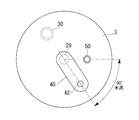
ディスチャージカバー3に吐出ポート29が一つのみ形成される場合、図3に示すように、板状部材であるリード弁40の一端と他端を結ぶ線と、吐出ポート29とインジェクション管50とを結ぶ線とは、90°未満であること、好ましくは、60°以下であることが望ましい。これにより、インジェクション管50が、吐出ポート29からの冷媒の吹き出し方向の後方側に設けられる位置となり、冷媒がインジェクション管50から離れる方向に確実に吹き出される。なお、図3では、リテーナ41の図示を省略している。
When only one discharge port 29 is formed in the discharge cover 3, as shown in FIG. 3, a line connecting one end and the other end of the reed valve 40 which is a plate-like member, the discharge port 29 and the injection pipe 50 The connecting line is desirably less than 90 °, preferably not more than 60 °. As a result, the injection pipe 50 is provided at the rear side in the blowout direction of the refrigerant from the discharge port 29, and the refrigerant is reliably blown out in the direction away from the injection pipe 50. In addition, illustration of the retainer 41 is abbreviate | omitted in FIG.
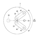
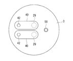
図2及び図4に示すように、ディスチャージカバー3に吐出ポート29が2箇所に形成され、各吐出ポート29に一つずつリード弁40が設けられるとき、板状部材である二つのリード弁40は、インジェクション管50を挟むように設置される。これにより、インジェクション管50が、二つの吐出ポート29からの冷媒の吹き出し方向の後方側に設けられる位置となり、冷媒がインジェクション管50から離れる方向に吹き出される。なお、図4では、リテーナ41の図示を省略している。
As shown in FIG. 2 and FIG. 4, when discharge ports 29 are formed in two places in the discharge cover 3 and one reed valve 40 is provided in each discharge port 29, two reed valves 40 which are plate-like members are provided. Are installed so as to sandwich the injection pipe 50. As a result, the injection pipe 50 is provided at the rear side in the blowout direction of the refrigerant from the two discharge ports 29, and the refrigerant is blown out in the direction away from the injection pipe 50. In addition, illustration of the retainer 41 is abbreviate | omitted in FIG.
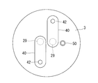
すなわち、図8及び図9に示すように、ディスチャージカバー3に吐出ポート29が一つのみ形成される場合と異なり、リード弁40の一端と他端を結ぶ線と、吐出ポート29とインジェクション管50とを結ぶ線とを90°以下にすることは難しい。リード弁40の一端と他端を結ぶ線と、吐出ポート29とインジェクション管50とを結ぶ線とを90°にできたとしても、吐出ポート29から吹き出された冷媒がインジェクション管50に当たる可能性がある。図8は、二つのリード弁を吐出ポート29に対して同じ側で固定した場合を示しており、図9は、二つのリード弁を吐出ポート29に対して異なる側で固定した場合を示している。
That is, as shown in FIGS. 8 and 9, unlike the case where only one discharge port 29 is formed in the discharge cover 3, a line connecting one end and the other end of the reed valve 40, the discharge port 29 and the injection pipe 50. It is difficult to make the line connecting them less than 90 °. Even if the line connecting one end and the other end of the reed valve 40 and the line connecting the discharge port 29 and the injection pipe 50 can be 90 °, the refrigerant blown out from the discharge port 29 may possibly hit the injection pipe 50 is there. 8 shows the case where two reed valves are fixed on the same side with respect to the discharge port 29, and FIG. 9 shows the case where two reed valves are fixed on different sides with respect to the discharge port 29. There is.
図4に示すように、二つのリード弁40が、インジェクション管50を挟むように設置されるとき、二つの吐出ポート29を結ぶ線分の垂直二等分線上に、インジェクション管50が設置される。このような配置関係とすることで、二つのリード弁40がインジェクション管50を挟むように設置でき、かつ、冷媒がインジェクション管50から離れる方向に吹き出される。
As shown in FIG. 4, when the two reed valves 40 are installed to sandwich the injection pipe 50, the injection pipe 50 is installed on a perpendicular bisector of a line connecting the two discharge ports 29. . With such an arrangement relationship, the two reed valves 40 can be installed so as to sandwich the injection pipe 50, and the refrigerant is blown out in the direction away from the injection pipe 50.
二つのリード弁40については、図4に示すように、一方のリード弁40の一端と他端を結ぶ線と、他方のリード弁40の一端と他端を結ぶ線とのなす角が、90°以下であることが望ましい。これにより、二つの吐出ポート29から吹き出される冷媒が互いに干渉することなく、かつ、冷媒がインジェクション管50から離れる方向に吹き出されるようにすることができる。
For the two reed valves 40, as shown in FIG. 4, the angle between the line connecting one end and the other end of one reed valve 40 and the line connecting the one end and the other end of the other reed valve 40 is 90 It is desirable that it is less than or equal to °. Thus, the refrigerant can be blown out in the direction away from the injection pipe 50 without the refrigerants blown out from the two discharge ports 29 interfering with each other.
以上、本実施形態によれば、吐出ポート29から吹き出される冷媒がインジェクション管50に直接当たらないため、インジェクション管50内部を流れる冷媒が加熱されにくい。その結果、インジェクション管50を通過して圧縮室20に供給される冷媒によって、圧縮室20の内部が適切に冷却され、密閉型スクロール圧縮機1の性能低下を防ぐことができる。
As described above, according to the present embodiment, since the refrigerant blown out from the discharge port 29 does not directly hit the injection pipe 50, the refrigerant flowing inside the injection pipe 50 is not easily heated. As a result, the inside of the compression chamber 20 is appropriately cooled by the refrigerant that passes through the injection pipe 50 and is supplied to the compression chamber 20, and the performance degradation of the hermetic scroll compressor 1 can be prevented.
上述した説明では、リード弁40によって規制された吐出ポート29から吹き出される冷媒の吹き出し方向と、インジェクション管50の位置の関係について説明したが、ハウジングに設置される吐出管30の位置を更に考慮してもよい。
In the above description, the relationship between the discharge direction of the refrigerant blown out from the discharge port 29 regulated by the reed valve 40 and the position of the injection pipe 50 has been described, but the position of the discharge pipe 30 installed in the housing is further considered You may
すなわち、吐出管30は、吐出ポート29から吐出チャンバー5へ吐出される冷媒が、リード弁40によって吐出管30へ近づく方向に吹き出されるように設置される。すなわち、吐出管30が、吐出ポート29からの冷媒の吹き出し方向の前方側に設けられる。これにより、吐出ポート29から吐出された冷媒は、インジェクション管50の方へ向かう量が減り、インジェクション管50内部を流れる冷媒が更に加熱されにくくなる。
That is, the discharge pipe 30 is installed such that the refrigerant discharged from the discharge port 29 to the discharge chamber 5 is blown out by the reed valve 40 in the direction approaching the discharge pipe 30. That is, the discharge pipe 30 is provided on the front side in the blowing direction of the refrigerant from the discharge port 29. As a result, the amount of the refrigerant discharged from the discharge port 29 toward the injection pipe 50 decreases, and the refrigerant flowing inside the injection pipe 50 becomes less likely to be heated.
ディスチャージカバー3に吐出ポート29が2箇所に形成され、各吐出ポート29に一つずつリード弁40が設けられる場合、吐出管30は、二つの吐出ポート29を結ぶ線を間に挟んで、インジェクション管50とは反対側に設けられる。好ましくは、吐出管30は、二つの吐出ポート29を結ぶ線分の垂直二等分線上に設置される。これにより、吐出ポート29から吐出された冷媒は、インジェクション管50の方へ向かう量が確実に減り、インジェクション管50内部を流れる冷媒が更に加熱されにくくなる。
When discharge ports 29 are formed at two locations in discharge cover 3 and one reed valve 40 is provided for each discharge port 29, discharge pipe 30 is provided with injection via a line connecting two discharge ports 29. It is provided on the opposite side to the tube 50. Preferably, the discharge pipe 30 is disposed on a vertical bisector of a line connecting two discharge ports 29. As a result, the amount of the refrigerant discharged from the discharge port 29 toward the injection pipe 50 is surely reduced, and the refrigerant flowing inside the injection pipe 50 is less likely to be heated.
また、上述した説明では、インジェクション管50が設置される場合について説明したが、密閉型スクロール圧縮機1においてインジェクション管50ではなく、バイパス管が設けられる場合も同様の配置関係とすることで、吐出ポート29から吹き出される冷媒がバイパス管に直接当たることを防止できる。その結果、バイパス管を流れる冷媒が加熱されないため、冷媒の体積が増えることなく、冷媒は、バイパス管を通過して密閉型スクロール圧縮機1の内部に戻される。この場合も、密閉型スクロール圧縮機1の性能低下を防ぐことができる。
Further, in the above description, the case where the injection pipe 50 is installed has been described, but in the case where a bypass pipe is provided instead of the injection pipe 50 in the enclosed scroll compressor 1, discharge is achieved by the same arrangement relationship. The refrigerant blown out from the port 29 can be prevented from directly impinging on the bypass pipe. As a result, since the refrigerant flowing in the bypass pipe is not heated, the refrigerant passes through the bypass pipe and is returned to the inside of the hermetic scroll compressor 1 without increasing the volume of the refrigerant. Also in this case, it is possible to prevent the performance of the hermetic scroll compressor 1 from being degraded.
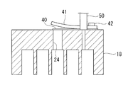
なお、上述した実施形態では、リード弁40が、ディスチャージカバー3に形成された吐出ポート29に対して設置される場合について説明したが、本発明はこの例に限定されない。すなわち、ディスチャージカバー3が設けられない場合などにおいて、リード弁40は、図5に示すように、固定スクロール18に形成された吐出口24に対して設置されてもよい。この場合も、上述した説明と同様に、リード弁40によって規制された吐出口24から吹き出される冷媒の吹き出し方向と、インジェクション管50の位置の関係に基づいて、リード弁40が設置される。また、吐出管30についても、上述した説明と同様に設置されてもよい。
In the embodiment described above, the case where the reed valve 40 is installed for the discharge port 29 formed in the discharge cover 3 has been described, but the present invention is not limited to this example. That is, in the case where the discharge cover 3 is not provided, the reed valve 40 may be installed to the discharge port 24 formed in the fixed scroll 18 as shown in FIG. 5. Also in this case, the reed valve 40 is installed based on the relationship between the blowing direction of the refrigerant blown out from the discharge port 24 regulated by the reed valve 40 and the position of the injection pipe 50 as in the above description. The discharge pipe 30 may also be installed in the same manner as described above.
リード弁40が、固定スクロール18に形成された吐出口24に対して設置される場合も、吐出口24から吹き出される冷媒がインジェクション管50に直接当たらないため、インジェクション管50内部を流れる冷媒が加熱されにくい。その結果、インジェクション管50を通過して圧縮室20に供給される冷媒によって、圧縮室20内部が適切に冷却され、圧縮機の性能低下を防ぐことができる。
Even when the reed valve 40 is installed to the discharge port 24 formed in the fixed scroll 18, the refrigerant blown out from the discharge port 24 does not directly hit the injection pipe 50, so the refrigerant flowing inside the injection pipe 50 is It is hard to be heated. As a result, the inside of the compression chamber 20 can be appropriately cooled by the refrigerant that passes through the injection pipe 50 and is supplied to the compression chamber 20, and the performance degradation of the compressor can be prevented.
1 :密閉型スクロール圧縮機
2 :密閉ハウジング
3 :ディスチャージカバー
4 :上部カバー
5 :吐出チャンバー
6 :上部軸受部材
6A :ジャーナル軸受部
6B :スラスト軸受部
7 :スクロール圧縮機構
8 :ステータ
8A :ステータ巻線
9 :ロータ
10 :電動モータ
11 :クランク軸
12 :クランクピン
13 :下部ジャーナル軸受
14 :容積型給油ポンプ
15 :潤滑油
16 :吸入パイプ
17 :流通路
18 :固定スクロール
18A :端板
18B :渦巻き状ラップ
19 :旋回スクロール
19A :端板
19B :渦巻き状ラップ
19C :軸受ボス
20 :圧縮室
21 :自転阻止機構
22 :ドライブブッシュ
24 :吐出口
25 :チップシール
26 :チップシール
27 :吸入配管
28 :吸入口
29 :吐出ポート
30 :吐出管
40 :リード弁
41 :リテーナ
42 :ボルト
50 :インジェクション管
DESCRIPTION OF SYMBOLS 1: Sealed scroll compressor 2: Sealed housing 3: Discharge cover 4: Upper cover 5: Discharge chamber 6:Upper bearing member 6A: Journal bearing portion 6B: Thrust bearing portion 7: Scroll compression mechanism 8: Stator 8A: Stator winding Line 9: Rotor 10: Electric motor 11: Crankshaft 12: Crank pin 13: Lower journal bearing 14: Displacement type oil pump 15: Lubricant oil 16: Suction pipe 17: Flow passage 18: Fixed scroll 18A: End plate 18B: Swirl 19: end plate 19B: spiral wrap 19C: bearing boss 20: compression chamber 21: rotation preventing mechanism 22: drive bush 24: discharge port 25: tip seal 26: tip seal 27: suction pipe 28: Inlet 29: Discharge Port 30: Discharge pipe 40: Reed valve 41: Retainer 42: Bolt 50: Injection pipe
2 :密閉ハウジング
3 :ディスチャージカバー
4 :上部カバー
5 :吐出チャンバー
6 :上部軸受部材
6A :ジャーナル軸受部
6B :スラスト軸受部
7 :スクロール圧縮機構
8 :ステータ
8A :ステータ巻線
9 :ロータ
10 :電動モータ
11 :クランク軸
12 :クランクピン
13 :下部ジャーナル軸受
14 :容積型給油ポンプ
15 :潤滑油
16 :吸入パイプ
17 :流通路
18 :固定スクロール
18A :端板
18B :渦巻き状ラップ
19 :旋回スクロール
19A :端板
19B :渦巻き状ラップ
19C :軸受ボス
20 :圧縮室
21 :自転阻止機構
22 :ドライブブッシュ
24 :吐出口
25 :チップシール
26 :チップシール
27 :吸入配管
28 :吸入口
29 :吐出ポート
30 :吐出管
40 :リード弁
41 :リテーナ
42 :ボルト
50 :インジェクション管
DESCRIPTION OF SYMBOLS 1: Sealed scroll compressor 2: Sealed housing 3: Discharge cover 4: Upper cover 5: Discharge chamber 6:
Claims (8)
- ハウジングと、
前記ハウジングに収容されたスクロール型の圧縮機構と、
前記圧縮機構で圧縮された冷媒が通過する吐出口が設けられたディスチャージカバー又は前記圧縮機構の固定スクロールと、
前記ハウジングと前記ディスチャージカバー又は前記固定スクロールとの間に形成された吐出チャンバーと、
前記吐出チャンバー内を通過して設けられ、内部を冷媒が流通する配管部と、
前記ディスチャージカバー又は前記固定スクロールの前記吐出口に設けられ、前記吐出口から前記吐出チャンバーへ吐出される冷媒が、前記配管部から離れる方向に吹き出される構成を有しているリード弁と、
を備える圧縮機。 With the housing,
A scroll type compression mechanism housed in the housing;
A discharge cover provided with a discharge port through which the refrigerant compressed by the compression mechanism passes, or a fixed scroll of the compression mechanism;
A discharge chamber formed between the housing and the discharge cover or the fixed scroll;
A piping portion which passes through the inside of the discharge chamber and through which the refrigerant flows;
A reed valve provided at the discharge port of the discharge cover or the fixed scroll and having a configuration in which a refrigerant discharged from the discharge port to the discharge chamber is blown out in a direction away from the piping section;
A compressor comprising: - 前記リード弁は、前記吐出口から吐出される冷媒を所定の吹き出し方向に吹き出させる板状部材を有し、
前記配管部は、前記吹き出し方向の後方側に設けられる請求項1に記載の圧縮機。 The reed valve has a plate-like member for blowing out the refrigerant discharged from the discharge port in a predetermined blowing direction,
The said piping part is a compressor of Claim 1 provided in the back side of the said blowing direction. - 前記リード弁の前記板状部材は、一方向に長く、一端側が前記ディスチャージカバー又は前記固定スクロールに固定され、他端側が前記吐出口に対して開閉可能であり、
前記板状部材の前記一端と前記他端を結ぶ線と、前記吐出口と前記配管部とを結ぶ線とは、90°以下である請求項2に記載の圧縮機。 The plate-like member of the reed valve is long in one direction, one end is fixed to the discharge cover or the fixed scroll, and the other end can be opened and closed with respect to the discharge port,
The compressor according to claim 2, wherein a line connecting the one end and the other end of the plate-like member and a line connecting the discharge port and the piping portion are 90 ° or less. - 前記リード弁の前記板状部材は、一方向に長く、一端側が前記ディスチャージカバー又は前記固定スクロールに固定され、他端側が前記吐出口に対して開閉可能であり、
前記吐出口が2箇所設けられ、各前記吐出口に一つずつ前記リード弁が設けられるとき、
二つの前記リード弁の前記板状部材は、前記配管部を挟むように設置される請求項2に記載の圧縮機。 The plate-like member of the reed valve is long in one direction, one end is fixed to the discharge cover or the fixed scroll, and the other end can be opened and closed with respect to the discharge port,
When the two discharge ports are provided and one reed valve is provided for each of the discharge ports,
The compressor according to claim 2, wherein the plate-like members of the two reed valves are installed to sandwich the pipe portion. - 二つの前記吐出口を結ぶ線分の垂直二等分線上に、前記配管部が設置される請求項4に記載の圧縮機。 The compressor according to claim 4, wherein the piping unit is installed on a perpendicular bisector of a line segment connecting two of the discharge ports.
- 一方の前記板状部材の前記一端と前記他端を結ぶ線と、他方の前記板状部材の前記一端と前記他端を結ぶ線とのなす角が、90°以下である請求項4又は5に記載の圧縮機。 The angle between the line connecting the one end and the other end of one plate member and the line connecting the one end and the other end of the other plate member is 90 ° or less. The compressor as described in.
- 前記ハウジングを貫通して設置され、前記吐出チャンバー内の冷媒を外部へ吐出する吐出管を更に備え、
前記吐出口から前記吐出チャンバーへ吐出される冷媒が、前記リード弁によって前記吐出管へ近づく方向に吹き出されるように、前記吐出管が設置されている請求項1から6のいずれか1項に記載の圧縮機。 It further comprises a discharge pipe installed through the housing and discharging the refrigerant in the discharge chamber to the outside,
The discharge pipe is installed such that the refrigerant discharged from the discharge port to the discharge chamber is blown out in the direction approaching the discharge pipe by the reed valve. Description compressor. - 前記ハウジングを貫通して設置され、前記吐出チャンバー内の冷媒を外部へ吐出する吐出管を更に備え、
前記吐出口から前記吐出チャンバーへ吐出される冷媒が、前記リード弁によって前記吐出管へ近づく方向に吹き出されるように、前記吐出管が設置され、かつ、前記吐出管は、二つの前記吐出口を結ぶ線を間に挟んで、前記配管部とは反対側に設置される請求項4から6のいずれか1項に記載の圧縮機。 It further comprises a discharge pipe installed through the housing and discharging the refrigerant in the discharge chamber to the outside,
The discharge pipe is installed such that the refrigerant discharged from the discharge port to the discharge chamber is blown by the reed valve in the direction approaching the discharge pipe, and the discharge pipe includes two discharge ports. The compressor according to any one of claims 4 to 6, wherein the compressor is installed on the opposite side of the pipe section with a line connecting the two.
Priority Applications (2)
| Application Number | Priority Date | Filing Date | Title |
|---|---|---|---|
| CN201780005285.XA CN108474378B (en) | 2016-03-04 | 2017-03-01 | Compressor with a compressor housing having a plurality of compressor blades |
| EP17760066.5A EP3382205B1 (en) | 2016-03-04 | 2017-03-01 | Compressor |
Applications Claiming Priority (2)
| Application Number | Priority Date | Filing Date | Title |
|---|---|---|---|
| JP2016-042114 | 2016-03-04 | ||
| JP2016042114A JP6710545B2 (en) | 2016-03-04 | 2016-03-04 | Compressor |
Publications (1)
| Publication Number | Publication Date |
|---|---|
| WO2017150602A1 true WO2017150602A1 (en) | 2017-09-08 |
Family
ID=59744113
Family Applications (1)
| Application Number | Title | Priority Date | Filing Date |
|---|---|---|---|
| PCT/JP2017/008085 WO2017150602A1 (en) | 2016-03-04 | 2017-03-01 | Compressor |
Country Status (4)
| Country | Link |
|---|---|
| EP (1) | EP3382205B1 (en) |
| JP (1) | JP6710545B2 (en) |
| CN (1) | CN108474378B (en) |
| WO (1) | WO2017150602A1 (en) |
Cited By (1)
| Publication number | Priority date | Publication date | Assignee | Title |
|---|---|---|---|---|
| EP3578823A1 (en) * | 2018-06-05 | 2019-12-11 | Mitsubishi Heavy Industries Thermal Systems, Ltd. | Compressor and method for manufacturing compressor |
Families Citing this family (5)
| Publication number | Priority date | Publication date | Assignee | Title |
|---|---|---|---|---|
| JP7154868B2 (en) * | 2018-08-02 | 2022-10-18 | 三菱重工サーマルシステムズ株式会社 | compressor |
| KR20210012292A (en) * | 2019-07-24 | 2021-02-03 | 한온시스템 주식회사 | Scroll compressor |
| KR20210105565A (en) * | 2020-02-19 | 2021-08-27 | 한온시스템 주식회사 | Scroll compressor |
| US11384759B2 (en) * | 2020-03-10 | 2022-07-12 | Hanon Systems | Vapor injection double reed valve plate |
| JP7366238B2 (en) * | 2020-03-27 | 2023-10-20 | 三菱電機株式会社 | scroll compressor |
Citations (6)
| Publication number | Priority date | Publication date | Assignee | Title |
|---|---|---|---|---|
| JPH0364686A (en) * | 1989-07-31 | 1991-03-20 | Sanden Corp | Scroll type compressor |
| JPH09158856A (en) * | 1995-12-05 | 1997-06-17 | Matsushita Electric Ind Co Ltd | Scroll gas compressor |
| US6299417B1 (en) * | 1999-10-04 | 2001-10-09 | Lg Electronics, Inc. | Back pressure structure of intermediate pressure of scroll compressor |
| JP2006348933A (en) * | 2005-05-17 | 2006-12-28 | Daikin Ind Ltd | Rotary compressor |
| JP2009287512A (en) * | 2008-05-30 | 2009-12-10 | Mitsubishi Heavy Ind Ltd | Refrigerant compressor and valve unit |
| JP2015098804A (en) * | 2013-11-18 | 2015-05-28 | 株式会社豊田自動織機 | Electric compressor |
Family Cites Families (4)
| Publication number | Priority date | Publication date | Assignee | Title |
|---|---|---|---|---|
| JPS58187594A (en) * | 1982-04-28 | 1983-11-01 | Hitachi Ltd | Scroll compressor |
| US5741120A (en) * | 1995-06-07 | 1998-04-21 | Copeland Corporation | Capacity modulated scroll machine |
| US5855475A (en) * | 1995-12-05 | 1999-01-05 | Matsushita Electric Industrial Co., Ltd. | Scroll compressor having bypass valves |
| CN100549424C (en) * | 2005-05-17 | 2009-10-14 | 大金工业株式会社 | Rotary compressor |
-
2016
- 2016-03-04 JP JP2016042114A patent/JP6710545B2/en active Active
-
2017
- 2017-03-01 WO PCT/JP2017/008085 patent/WO2017150602A1/en active Application Filing
- 2017-03-01 CN CN201780005285.XA patent/CN108474378B/en active Active
- 2017-03-01 EP EP17760066.5A patent/EP3382205B1/en active Active
Patent Citations (6)
| Publication number | Priority date | Publication date | Assignee | Title |
|---|---|---|---|---|
| JPH0364686A (en) * | 1989-07-31 | 1991-03-20 | Sanden Corp | Scroll type compressor |
| JPH09158856A (en) * | 1995-12-05 | 1997-06-17 | Matsushita Electric Ind Co Ltd | Scroll gas compressor |
| US6299417B1 (en) * | 1999-10-04 | 2001-10-09 | Lg Electronics, Inc. | Back pressure structure of intermediate pressure of scroll compressor |
| JP2006348933A (en) * | 2005-05-17 | 2006-12-28 | Daikin Ind Ltd | Rotary compressor |
| JP2009287512A (en) * | 2008-05-30 | 2009-12-10 | Mitsubishi Heavy Ind Ltd | Refrigerant compressor and valve unit |
| JP2015098804A (en) * | 2013-11-18 | 2015-05-28 | 株式会社豊田自動織機 | Electric compressor |
Cited By (1)
| Publication number | Priority date | Publication date | Assignee | Title |
|---|---|---|---|---|
| EP3578823A1 (en) * | 2018-06-05 | 2019-12-11 | Mitsubishi Heavy Industries Thermal Systems, Ltd. | Compressor and method for manufacturing compressor |
Also Published As
| Publication number | Publication date |
|---|---|
| CN108474378B (en) | 2020-10-27 |
| JP2017155719A (en) | 2017-09-07 |
| CN108474378A (en) | 2018-08-31 |
| EP3382205B1 (en) | 2020-11-18 |
| EP3382205A4 (en) | 2018-11-07 |
| JP6710545B2 (en) | 2020-06-17 |
| EP3382205A1 (en) | 2018-10-03 |
Similar Documents
| Publication | Publication Date | Title |
|---|---|---|
| WO2017150602A1 (en) | Compressor | |
| US8998596B2 (en) | Scroll compressor | |
| KR102408562B1 (en) | Scroll compressor | |
| US11566620B2 (en) | Motor driven compressor apparatus including swing pin | |
| US8690555B2 (en) | Two-stage rotary expander, expander-compressor unit, and refrigeration cycle apparatus | |
| US7588428B2 (en) | Rotary fluid device performing compression and expansion of fluid within a common cylinder | |
| JP2010053798A (en) | Scroll compressor | |
| JP5515289B2 (en) | Refrigeration equipment | |
| JP4696530B2 (en) | Fluid machinery | |
| JP4930314B2 (en) | Positive displacement expander, expander-integrated compressor, and refrigeration cycle apparatus | |
| JP4682795B2 (en) | Expander-integrated compressor and refrigeration cycle apparatus | |
| KR100557061B1 (en) | Scroll compressor | |
| KR102392491B1 (en) | Scroll type compressor | |
| JP5209279B2 (en) | Scroll compressor | |
| JP2008267345A (en) | Electric compressor | |
| JP2017172346A (en) | Scroll compressor and air conditioner | |
| AU2007237797A1 (en) | Fluid machine | |
| WO2022264792A1 (en) | Scroll compressor | |
| JP3574904B2 (en) | Closed displacement compressor | |
| CN114222861B (en) | Scroll compressor having a rotor with a rotor shaft having a rotor shaft with a | |
| JP2006132332A (en) | Fluid machine | |
| JP4879078B2 (en) | Compressor | |
| JP2018031292A (en) | Scroll compressor | |
| JP2008002422A (en) | Scroll compressor | |
| WO2021038738A1 (en) | Scroll compressor |
Legal Events
| Date | Code | Title | Description |
|---|---|---|---|
| WWE | Wipo information: entry into national phase |
Ref document number: 2017760066 Country of ref document: EP |
|
| ENP | Entry into the national phase |
Ref document number: 2017760066 Country of ref document: EP Effective date: 20180629 |
|
| NENP | Non-entry into the national phase |
Ref country code: DE |