EP3381041B1 - Elektrische anschlusseinrichtung - Google Patents
Elektrische anschlusseinrichtung Download PDFInfo
- Publication number
- EP3381041B1 EP3381041B1 EP16787729.9A EP16787729A EP3381041B1 EP 3381041 B1 EP3381041 B1 EP 3381041B1 EP 16787729 A EP16787729 A EP 16787729A EP 3381041 B1 EP3381041 B1 EP 3381041B1
- Authority
- EP
- European Patent Office
- Prior art keywords
- connection device
- valve
- temperature sensor
- plug
- contact
- Prior art date
- Legal status (The legal status is an assumption and is not a legal conclusion. Google has not performed a legal analysis and makes no representation as to the accuracy of the status listed.)
- Active
Links
Images

Classifications
-
- H—ELECTRICITY
- H01—ELECTRIC ELEMENTS
- H01F—MAGNETS; INDUCTANCES; TRANSFORMERS; SELECTION OF MATERIALS FOR THEIR MAGNETIC PROPERTIES
- H01F7/00—Magnets
- H01F7/06—Electromagnets; Actuators including electromagnets
- H01F7/08—Electromagnets; Actuators including electromagnets with armatures
- H01F7/127—Assembling
-
- A—HUMAN NECESSITIES
- A01—AGRICULTURE; FORESTRY; ANIMAL HUSBANDRY; HUNTING; TRAPPING; FISHING
- A01N—PRESERVATION OF BODIES OF HUMANS OR ANIMALS OR PLANTS OR PARTS THEREOF; BIOCIDES, e.g. AS DISINFECTANTS, AS PESTICIDES OR AS HERBICIDES; PEST REPELLANTS OR ATTRACTANTS; PLANT GROWTH REGULATORS
- A01N31/00—Biocides, pest repellants or attractants, or plant growth regulators containing organic oxygen or sulfur compounds
- A01N31/02—Acyclic compounds
-
- A—HUMAN NECESSITIES
- A01—AGRICULTURE; FORESTRY; ANIMAL HUSBANDRY; HUNTING; TRAPPING; FISHING
- A01N—PRESERVATION OF BODIES OF HUMANS OR ANIMALS OR PLANTS OR PARTS THEREOF; BIOCIDES, e.g. AS DISINFECTANTS, AS PESTICIDES OR AS HERBICIDES; PEST REPELLANTS OR ATTRACTANTS; PLANT GROWTH REGULATORS
- A01N65/00—Biocides, pest repellants or attractants, or plant growth regulators containing material from algae, lichens, bryophyta, multi-cellular fungi or plants, or extracts thereof
- A01N65/08—Magnoliopsida [dicotyledons]
- A01N65/22—Lamiaceae or Labiatae [Mint family], e.g. thyme, rosemary, skullcap, selfheal, lavender, perilla, pennyroyal, peppermint or spearmint
-
- F—MECHANICAL ENGINEERING; LIGHTING; HEATING; WEAPONS; BLASTING
- F16—ENGINEERING ELEMENTS AND UNITS; GENERAL MEASURES FOR PRODUCING AND MAINTAINING EFFECTIVE FUNCTIONING OF MACHINES OR INSTALLATIONS; THERMAL INSULATION IN GENERAL
- F16K—VALVES; TAPS; COCKS; ACTUATING-FLOATS; DEVICES FOR VENTING OR AERATING
- F16K1/00—Lift valves or globe valves, i.e. cut-off apparatus with closure members having at least a component of their opening and closing motion perpendicular to the closing faces
- F16K1/30—Lift valves or globe valves, i.e. cut-off apparatus with closure members having at least a component of their opening and closing motion perpendicular to the closing faces specially adapted for pressure containers
-
- F—MECHANICAL ENGINEERING; LIGHTING; HEATING; WEAPONS; BLASTING
- F16—ENGINEERING ELEMENTS AND UNITS; GENERAL MEASURES FOR PRODUCING AND MAINTAINING EFFECTIVE FUNCTIONING OF MACHINES OR INSTALLATIONS; THERMAL INSULATION IN GENERAL
- F16K—VALVES; TAPS; COCKS; ACTUATING-FLOATS; DEVICES FOR VENTING OR AERATING
- F16K31/00—Actuating devices; Operating means; Releasing devices
- F16K31/02—Actuating devices; Operating means; Releasing devices electric; magnetic
- F16K31/06—Actuating devices; Operating means; Releasing devices electric; magnetic using a magnet, e.g. diaphragm valves, cutting off by means of a liquid
-
- F—MECHANICAL ENGINEERING; LIGHTING; HEATING; WEAPONS; BLASTING
- F16—ENGINEERING ELEMENTS AND UNITS; GENERAL MEASURES FOR PRODUCING AND MAINTAINING EFFECTIVE FUNCTIONING OF MACHINES OR INSTALLATIONS; THERMAL INSULATION IN GENERAL
- F16K—VALVES; TAPS; COCKS; ACTUATING-FLOATS; DEVICES FOR VENTING OR AERATING
- F16K31/00—Actuating devices; Operating means; Releasing devices
- F16K31/02—Actuating devices; Operating means; Releasing devices electric; magnetic
- F16K31/06—Actuating devices; Operating means; Releasing devices electric; magnetic using a magnet, e.g. diaphragm valves, cutting off by means of a liquid
- F16K31/0675—Electromagnet aspects, e.g. electric supply therefor
-
- F—MECHANICAL ENGINEERING; LIGHTING; HEATING; WEAPONS; BLASTING
- F16—ENGINEERING ELEMENTS AND UNITS; GENERAL MEASURES FOR PRODUCING AND MAINTAINING EFFECTIVE FUNCTIONING OF MACHINES OR INSTALLATIONS; THERMAL INSULATION IN GENERAL
- F16K—VALVES; TAPS; COCKS; ACTUATING-FLOATS; DEVICES FOR VENTING OR AERATING
- F16K37/00—Special means in or on valves or other cut-off apparatus for indicating or recording operation thereof, or for enabling an alarm to be given
- F16K37/0025—Electrical or magnetic means
-
- F—MECHANICAL ENGINEERING; LIGHTING; HEATING; WEAPONS; BLASTING
- F17—STORING OR DISTRIBUTING GASES OR LIQUIDS
- F17C—VESSELS FOR CONTAINING OR STORING COMPRESSED, LIQUEFIED OR SOLIDIFIED GASES; FIXED-CAPACITY GAS-HOLDERS; FILLING VESSELS WITH, OR DISCHARGING FROM VESSELS, COMPRESSED, LIQUEFIED, OR SOLIDIFIED GASES
- F17C13/00—Details of vessels or of the filling or discharging of vessels
- F17C13/04—Arrangement or mounting of valves
-
- F—MECHANICAL ENGINEERING; LIGHTING; HEATING; WEAPONS; BLASTING
- F17—STORING OR DISTRIBUTING GASES OR LIQUIDS
- F17C—VESSELS FOR CONTAINING OR STORING COMPRESSED, LIQUEFIED OR SOLIDIFIED GASES; FIXED-CAPACITY GAS-HOLDERS; FILLING VESSELS WITH, OR DISCHARGING FROM VESSELS, COMPRESSED, LIQUEFIED, OR SOLIDIFIED GASES
- F17C2205/00—Vessel construction, in particular mounting arrangements, attachments or identifications means
- F17C2205/01—Mounting arrangements
- F17C2205/0123—Mounting arrangements characterised by number of vessels
- F17C2205/013—Two or more vessels
- F17C2205/0134—Two or more vessels characterised by the presence of fluid connection between vessels
-
- F—MECHANICAL ENGINEERING; LIGHTING; HEATING; WEAPONS; BLASTING
- F17—STORING OR DISTRIBUTING GASES OR LIQUIDS
- F17C—VESSELS FOR CONTAINING OR STORING COMPRESSED, LIQUEFIED OR SOLIDIFIED GASES; FIXED-CAPACITY GAS-HOLDERS; FILLING VESSELS WITH, OR DISCHARGING FROM VESSELS, COMPRESSED, LIQUEFIED, OR SOLIDIFIED GASES
- F17C2205/00—Vessel construction, in particular mounting arrangements, attachments or identifications means
- F17C2205/03—Fluid connections, filters, valves, closure means or other attachments
- F17C2205/0302—Fittings, valves, filters, or components in connection with the gas storage device
- F17C2205/0323—Valves
-
- F—MECHANICAL ENGINEERING; LIGHTING; HEATING; WEAPONS; BLASTING
- F17—STORING OR DISTRIBUTING GASES OR LIQUIDS
- F17C—VESSELS FOR CONTAINING OR STORING COMPRESSED, LIQUEFIED OR SOLIDIFIED GASES; FIXED-CAPACITY GAS-HOLDERS; FILLING VESSELS WITH, OR DISCHARGING FROM VESSELS, COMPRESSED, LIQUEFIED, OR SOLIDIFIED GASES
- F17C2205/00—Vessel construction, in particular mounting arrangements, attachments or identifications means
- F17C2205/03—Fluid connections, filters, valves, closure means or other attachments
- F17C2205/0302—Fittings, valves, filters, or components in connection with the gas storage device
- F17C2205/0323—Valves
- F17C2205/0326—Valves electrically actuated
-
- F—MECHANICAL ENGINEERING; LIGHTING; HEATING; WEAPONS; BLASTING
- F17—STORING OR DISTRIBUTING GASES OR LIQUIDS
- F17C—VESSELS FOR CONTAINING OR STORING COMPRESSED, LIQUEFIED OR SOLIDIFIED GASES; FIXED-CAPACITY GAS-HOLDERS; FILLING VESSELS WITH, OR DISCHARGING FROM VESSELS, COMPRESSED, LIQUEFIED, OR SOLIDIFIED GASES
- F17C2205/00—Vessel construction, in particular mounting arrangements, attachments or identifications means
- F17C2205/03—Fluid connections, filters, valves, closure means or other attachments
- F17C2205/0302—Fittings, valves, filters, or components in connection with the gas storage device
- F17C2205/0323—Valves
- F17C2205/0329—Valves manually actuated
-
- F—MECHANICAL ENGINEERING; LIGHTING; HEATING; WEAPONS; BLASTING
- F17—STORING OR DISTRIBUTING GASES OR LIQUIDS
- F17C—VESSELS FOR CONTAINING OR STORING COMPRESSED, LIQUEFIED OR SOLIDIFIED GASES; FIXED-CAPACITY GAS-HOLDERS; FILLING VESSELS WITH, OR DISCHARGING FROM VESSELS, COMPRESSED, LIQUEFIED, OR SOLIDIFIED GASES
- F17C2205/00—Vessel construction, in particular mounting arrangements, attachments or identifications means
- F17C2205/03—Fluid connections, filters, valves, closure means or other attachments
- F17C2205/0302—Fittings, valves, filters, or components in connection with the gas storage device
- F17C2205/0323—Valves
- F17C2205/0332—Safety valves or pressure relief valves
-
- F—MECHANICAL ENGINEERING; LIGHTING; HEATING; WEAPONS; BLASTING
- F17—STORING OR DISTRIBUTING GASES OR LIQUIDS
- F17C—VESSELS FOR CONTAINING OR STORING COMPRESSED, LIQUEFIED OR SOLIDIFIED GASES; FIXED-CAPACITY GAS-HOLDERS; FILLING VESSELS WITH, OR DISCHARGING FROM VESSELS, COMPRESSED, LIQUEFIED, OR SOLIDIFIED GASES
- F17C2205/00—Vessel construction, in particular mounting arrangements, attachments or identifications means
- F17C2205/03—Fluid connections, filters, valves, closure means or other attachments
- F17C2205/0302—Fittings, valves, filters, or components in connection with the gas storage device
- F17C2205/0323—Valves
- F17C2205/0335—Check-valves or non-return valves
-
- F—MECHANICAL ENGINEERING; LIGHTING; HEATING; WEAPONS; BLASTING
- F17—STORING OR DISTRIBUTING GASES OR LIQUIDS
- F17C—VESSELS FOR CONTAINING OR STORING COMPRESSED, LIQUEFIED OR SOLIDIFIED GASES; FIXED-CAPACITY GAS-HOLDERS; FILLING VESSELS WITH, OR DISCHARGING FROM VESSELS, COMPRESSED, LIQUEFIED, OR SOLIDIFIED GASES
- F17C2205/00—Vessel construction, in particular mounting arrangements, attachments or identifications means
- F17C2205/03—Fluid connections, filters, valves, closure means or other attachments
- F17C2205/0302—Fittings, valves, filters, or components in connection with the gas storage device
- F17C2205/0382—Constructional details of valves, regulators
-
- F—MECHANICAL ENGINEERING; LIGHTING; HEATING; WEAPONS; BLASTING
- F17—STORING OR DISTRIBUTING GASES OR LIQUIDS
- F17C—VESSELS FOR CONTAINING OR STORING COMPRESSED, LIQUEFIED OR SOLIDIFIED GASES; FIXED-CAPACITY GAS-HOLDERS; FILLING VESSELS WITH, OR DISCHARGING FROM VESSELS, COMPRESSED, LIQUEFIED, OR SOLIDIFIED GASES
- F17C2205/00—Vessel construction, in particular mounting arrangements, attachments or identifications means
- F17C2205/03—Fluid connections, filters, valves, closure means or other attachments
- F17C2205/0302—Fittings, valves, filters, or components in connection with the gas storage device
- F17C2205/0382—Constructional details of valves, regulators
- F17C2205/0385—Constructional details of valves, regulators in blocks or units
-
- F—MECHANICAL ENGINEERING; LIGHTING; HEATING; WEAPONS; BLASTING
- F17—STORING OR DISTRIBUTING GASES OR LIQUIDS
- F17C—VESSELS FOR CONTAINING OR STORING COMPRESSED, LIQUEFIED OR SOLIDIFIED GASES; FIXED-CAPACITY GAS-HOLDERS; FILLING VESSELS WITH, OR DISCHARGING FROM VESSELS, COMPRESSED, LIQUEFIED, OR SOLIDIFIED GASES
- F17C2205/00—Vessel construction, in particular mounting arrangements, attachments or identifications means
- F17C2205/03—Fluid connections, filters, valves, closure means or other attachments
- F17C2205/0388—Arrangement of valves, regulators, filters
- F17C2205/0394—Arrangement of valves, regulators, filters in direct contact with the pressure vessel
-
- F—MECHANICAL ENGINEERING; LIGHTING; HEATING; WEAPONS; BLASTING
- F17—STORING OR DISTRIBUTING GASES OR LIQUIDS
- F17C—VESSELS FOR CONTAINING OR STORING COMPRESSED, LIQUEFIED OR SOLIDIFIED GASES; FIXED-CAPACITY GAS-HOLDERS; FILLING VESSELS WITH, OR DISCHARGING FROM VESSELS, COMPRESSED, LIQUEFIED, OR SOLIDIFIED GASES
- F17C2221/00—Handled fluid, in particular type of fluid
- F17C2221/01—Pure fluids
- F17C2221/012—Hydrogen
-
- F—MECHANICAL ENGINEERING; LIGHTING; HEATING; WEAPONS; BLASTING
- F17—STORING OR DISTRIBUTING GASES OR LIQUIDS
- F17C—VESSELS FOR CONTAINING OR STORING COMPRESSED, LIQUEFIED OR SOLIDIFIED GASES; FIXED-CAPACITY GAS-HOLDERS; FILLING VESSELS WITH, OR DISCHARGING FROM VESSELS, COMPRESSED, LIQUEFIED, OR SOLIDIFIED GASES
- F17C2221/00—Handled fluid, in particular type of fluid
- F17C2221/03—Mixtures
- F17C2221/032—Hydrocarbons
- F17C2221/033—Methane, e.g. natural gas, CNG, LNG, GNL, GNC, PLNG
-
- F—MECHANICAL ENGINEERING; LIGHTING; HEATING; WEAPONS; BLASTING
- F17—STORING OR DISTRIBUTING GASES OR LIQUIDS
- F17C—VESSELS FOR CONTAINING OR STORING COMPRESSED, LIQUEFIED OR SOLIDIFIED GASES; FIXED-CAPACITY GAS-HOLDERS; FILLING VESSELS WITH, OR DISCHARGING FROM VESSELS, COMPRESSED, LIQUEFIED, OR SOLIDIFIED GASES
- F17C2223/00—Handled fluid before transfer, i.e. state of fluid when stored in the vessel or before transfer from the vessel
- F17C2223/01—Handled fluid before transfer, i.e. state of fluid when stored in the vessel or before transfer from the vessel characterised by the phase
- F17C2223/0107—Single phase
- F17C2223/0123—Single phase gaseous, e.g. CNG, GNC
-
- F—MECHANICAL ENGINEERING; LIGHTING; HEATING; WEAPONS; BLASTING
- F17—STORING OR DISTRIBUTING GASES OR LIQUIDS
- F17C—VESSELS FOR CONTAINING OR STORING COMPRESSED, LIQUEFIED OR SOLIDIFIED GASES; FIXED-CAPACITY GAS-HOLDERS; FILLING VESSELS WITH, OR DISCHARGING FROM VESSELS, COMPRESSED, LIQUEFIED, OR SOLIDIFIED GASES
- F17C2223/00—Handled fluid before transfer, i.e. state of fluid when stored in the vessel or before transfer from the vessel
- F17C2223/03—Handled fluid before transfer, i.e. state of fluid when stored in the vessel or before transfer from the vessel characterised by the pressure level
- F17C2223/035—High pressure (>10 bar)
-
- F—MECHANICAL ENGINEERING; LIGHTING; HEATING; WEAPONS; BLASTING
- F17—STORING OR DISTRIBUTING GASES OR LIQUIDS
- F17C—VESSELS FOR CONTAINING OR STORING COMPRESSED, LIQUEFIED OR SOLIDIFIED GASES; FIXED-CAPACITY GAS-HOLDERS; FILLING VESSELS WITH, OR DISCHARGING FROM VESSELS, COMPRESSED, LIQUEFIED, OR SOLIDIFIED GASES
- F17C2223/00—Handled fluid before transfer, i.e. state of fluid when stored in the vessel or before transfer from the vessel
- F17C2223/03—Handled fluid before transfer, i.e. state of fluid when stored in the vessel or before transfer from the vessel characterised by the pressure level
- F17C2223/036—Very high pressure (>80 bar)
-
- F—MECHANICAL ENGINEERING; LIGHTING; HEATING; WEAPONS; BLASTING
- F17—STORING OR DISTRIBUTING GASES OR LIQUIDS
- F17C—VESSELS FOR CONTAINING OR STORING COMPRESSED, LIQUEFIED OR SOLIDIFIED GASES; FIXED-CAPACITY GAS-HOLDERS; FILLING VESSELS WITH, OR DISCHARGING FROM VESSELS, COMPRESSED, LIQUEFIED, OR SOLIDIFIED GASES
- F17C2250/00—Accessories; Control means; Indicating, measuring or monitoring of parameters
- F17C2250/04—Indicating or measuring of parameters as input values
- F17C2250/0404—Parameters indicated or measured
- F17C2250/0439—Temperature
-
- F—MECHANICAL ENGINEERING; LIGHTING; HEATING; WEAPONS; BLASTING
- F17—STORING OR DISTRIBUTING GASES OR LIQUIDS
- F17C—VESSELS FOR CONTAINING OR STORING COMPRESSED, LIQUEFIED OR SOLIDIFIED GASES; FIXED-CAPACITY GAS-HOLDERS; FILLING VESSELS WITH, OR DISCHARGING FROM VESSELS, COMPRESSED, LIQUEFIED, OR SOLIDIFIED GASES
- F17C2270/00—Applications
- F17C2270/01—Applications for fluid transport or storage
- F17C2270/0165—Applications for fluid transport or storage on the road
- F17C2270/0168—Applications for fluid transport or storage on the road by vehicles
- F17C2270/0178—Cars
-
- H—ELECTRICITY
- H01—ELECTRIC ELEMENTS
- H01F—MAGNETS; INDUCTANCES; TRANSFORMERS; SELECTION OF MATERIALS FOR THEIR MAGNETIC PROPERTIES
- H01F7/00—Magnets
- H01F7/06—Electromagnets; Actuators including electromagnets
- H01F2007/062—Details of terminals or connectors for electromagnets
-
- Y—GENERAL TAGGING OF NEW TECHNOLOGICAL DEVELOPMENTS; GENERAL TAGGING OF CROSS-SECTIONAL TECHNOLOGIES SPANNING OVER SEVERAL SECTIONS OF THE IPC; TECHNICAL SUBJECTS COVERED BY FORMER USPC CROSS-REFERENCE ART COLLECTIONS [XRACs] AND DIGESTS
- Y02—TECHNOLOGIES OR APPLICATIONS FOR MITIGATION OR ADAPTATION AGAINST CLIMATE CHANGE
- Y02E—REDUCTION OF GREENHOUSE GAS [GHG] EMISSIONS, RELATED TO ENERGY GENERATION, TRANSMISSION OR DISTRIBUTION
- Y02E60/00—Enabling technologies; Technologies with a potential or indirect contribution to GHG emissions mitigation
- Y02E60/30—Hydrogen technology
- Y02E60/32—Hydrogen storage
Definitions
- the invention relates to an electrical connection device with a contact plug according to the closer defined in the preamble of claim 1.
- the invention also relates to an electromagnetic valve with a temperature sensor and such an electrical connection device. Furthermore, the invention relates to the use of such an electromagnetic valve.
- Electromagnetic valves with a temperature sensor are known from the prior art and are used for example in pressurized gas containers, on the one hand to detect the temperature of the medium in the pressurized gas container and on the other hand, for example, to control a removal of the medium from the pressurized gas container via the electromagnetic valve.
- a temperature sensor By way of example may be in the context of DE 10 2014 002 660 A1 be referenced, which describes such a structure.
- the object of the present invention is now to provide an electrical connection device for an electromagnetic valve and an electromagnetic valve, which / which avoids the disadvantages mentioned and allows easy and reliable installation.
- the electrical contact plug is part of a housing, which also has an actuator coil for the valve and a plug contact for electrically contacting the temperature sensor during assembly of the housing having the valve.
- the electrical connection device thus consists essentially of a housing, which on the one hand has a contact plug, so as to ensure, for example, the contact with an electrical connection line, in particular a wiring harness in a vehicle application.
- a contact plug while a very simple in terms of installation and thus less error-prone contacting is possible.
- the electrical connection device itself in this case directly comprises the actuator coil for the electromagnetic valve, so that it can be mounted together with the housing and not separately mounted and connected.
- the electrical connection device comprises a plug contact, which is contacted during assembly with the temperature sensor.
- the temperature sensor is mounted, for example, as in the aforementioned DE 10 2014 002 660 A1 is described. It is accessible from the rear side, ie the side of the electromagnetic valve device facing away from the pressurized medium, when used as a tank valve in a pressurized gas container, via a bore. This makes the assembly and the electrical contact with the conventional structures extremely expensive.
- a contacting of the temperature sensor can now be easily achieved via the plug contact, for example by this is designed so that it extends over a hole to the temperature sensor or its electrical connections. Then, by the sole placement of the electrical connection device with the integrated coil and the successful completion of the contacting of the electrical temperature sensor a connection of all necessary electrical connections can be achieved. This makes assembly extremely easy, efficient and fault-tolerant.
- the plug contact is in accordance with an advantageous development of the idea as well as the coil connected to the contact plug, so that via this single contact plug, the connection can be made, for example, the connection with a harness for driving the electromagnetic valve on the one hand and for the evaluation of temperature data on the other.
- the object according to the invention is also achieved by an electromagnetic valve with a temperature sensor and such an electrical connection device according to the invention.
- An advantageous development of the electromagnetic valve device according to the invention provides in this case that the temperature sensor and / or its inclusion in the valve has a mark for angularly accurate mounting.
- Such a marking for angularly accurate mounting of the temperature sensor makes a reliable mounting of the above-described electrical connection device according to the invention very simple. Due to the exact angular orientation of the temperature sensor and its electrical contacts are aligned precisely to the angle, without having to resort to specially trained contacts such as annular contacts here. Rather, a sufficiently accurate interaction with the mating contacts in the plug contact can be achieved by a precise angular mounting of the temperature sensor, so that the assembly and the structure of the electrical connection device according to the invention is thereby further simplified.
- connection device is connected to the valve via a single releasable connection means.
- a connection means may in particular be a screw arranged axially and centrally in the region of the coil.
- the plug contact of the connection device and the temperature sensor at an angle of 90 ° to each other. This allows a contacting of the components not in alignment with each other, but at an angle to each other, which is extremely reliable in terms of assembly and very reliable even with higher component tolerances, when the electrical contacts have sufficient flexibility and size.
- the electromagnetic valve with a temperature sensor and the ability to mount it extremely easily and efficiently via the electrical connection device is now particularly suitable for use in applications which require correspondingly high numbers of units. It can therefore be used in particular in the field of tank valves of pressurized gas containers, especially when the pressurized gas containers find their preferred use for storing fuel in the form of compressed natural gas or compressed hydrogen in vehicles.
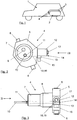
- FIG. 1 is purely exemplary of a vehicle 1 indicated.
- a gaseous fuel such as compressed natural gas or compressed hydrogen.
- the fuel can be converted, for example, in an internal combustion engine or in particular in a fuel cell system, in the case of hydrogen, in drive power.
- a memory device 2 is provided in the vehicle 1.
- the storage device 2 typically comprises a plurality of individual compressed gas containers 3, which in the illustration of FIG. 1 are indicated.
- Each of these compressed gas tank 3 carries a connected thereto tank valve 4, which is also referred to as OTV (On Tank Valve).
- OTV On Tank Valve
- An exemplary construction of such a tank valve is shown in the illustrations of FIGS. 2 and 3 indicated.
- the tank valve 4 is designed as an electromagnetic tank valve 4. It may for example be realized in the form of a so-called pilot valve, which is fundamentally known from the prior art, and exemplified in the DE 10 2013 019 879 A1 the applicant is described.
- the tank valve 4 comprises a valve housing 5, to which purely by way of example two connections designated 6 are indicated, for example, for the supply and removal of gas.
- a region designated 7 can be seen, which projects into the compressed gas container 3 in the mounted state of the tank valve 4.
- this protruding in the direction of the gas cylinder portion 7 has a designated 8 thread, which in the illustration of FIG. 3 is indicated. With this thread 8, the tank valve 4 with the corresponding receptacle, which is typically referred to as BOSS, screwed to the gas cylinder 3.
- the area 7 points, as again in the representation of the FIG. 2 can be seen, a communication connection designated 9, via which gas can flow into the compressed gas container and from the pressurized gas container to the tank valve 4.
- a temperature sensor 10 is provided. This is in a conventional manner, and for example in the manner as by the aforementioned DE 10 2014 002 660 A1 described, formed and includes a shell, which encloses the actual sensor element, for example, an NTC resistor.
- This temperature sensor 10 with its casing can be screwed to the region 7, for example. He has in particular one in the representation of FIG. 2 to be recognized surface 11, which also in the representation of FIG. 3 indicated by a cross as area. This allows an angular orientation of the temperature sensor 10 during assembly, which may be useful for reasons described later.
- the electromagnetically actuated valve 4 For actuating the electromagnetically actuated valve 4, this has as an actuator to an electromagnetic coil 12, which in particular in the representation of FIG. 2 is very easy to recognize. It is located in a housing 13 of a designated in its entirety by 14 electrical connection device. This has, in addition to the electromagnetic coil 12 as a further part of the housing 13 on a contact plug 15, via which a connection can be made for example on a wiring harness of the vehicle 1, so as to control the electromagnetic coil 12 as the actuator coil of the tank valve 4.
- the electrical connection device 14 is shown in an exemplary three-dimensional representation in FIG FIG. 4 to recognize.
- the designated in its entirety with 13 housing has the actuator coil 12 in particular in the housing 13 potted.
- the contact plug 15 can be seen.
- the actuator coil 12 can by a in the illustration of the FIG. 4 16 denotes the central opening in the actuator coil 12 a in the FIGS. 2 and 3 17 with the designated screw so as to screw the electrical connection device 14 with the valve housing 5.
- the actuator coil 12 may then cooperate with the corresponding parts of, for example, the pilot valve in the valve housing 5 in the desired manner.
- the electrical connection device 14 also has a designated 18 plug contact. This runs parallel to the axis of the actuator coil 12 and extends in the mounted state of the electrical connection device 14 into the valve housing 5 inside. This is in the presentation of FIG. 2 indicated by dashed lines.
- the valve housing 5 has for this purpose a suitable opening 19 into which the plug contact 18 can protrude.
- the temperature sensor 10 protrudes through the entire area 7 of the tank valve 4, for example, in turn, analogous to the aforementioned DE document. He typically has in its valve housing 5 end facing corresponding connection elements, which are not visible here. It ends in the region of the opening 19 for the plug contact 18. If now the electrical connection element 14 is mounted on the valve housing 5, then the plug contact 18 protrudes into the valve housing 5 and comes into an electrically connecting engagement with the temperature sensor 10 and its valve housing 5 facing plug contacts. To ensure this contact, which is typically done by a rectangular mating of the plug-in contact 18 and the temperature sensor 10, safe and reliable, it is, as already mentioned, important that the angular orientation of the temperature sensor 10 is right. For this purpose, different measures and markers could be provided. In the embodiment shown here, this is achieved by the surface designated 11, which is aligned so that it, for example, parallel to the edge of the valve housing 5, on which the electrical connection device 14 is mounted.
- the temperature sensor 10 When the temperature sensor 10 is mounted, a contacting of the temperature sensor 10 with the plug contact 18 and thus ultimately with the contact plug 15 of the electrical connection device 14 can be achieved by simply plugging in the electrical connection device 14.
- the actuator coil 12 is also connected within the electrical connection device 14 to further poles of the contact plug 15. It is therefore enough to plug the electrical connection device 14 in order to achieve the corresponding contact. Subsequently, it can, as already mentioned, be secured by the screw 17.
- the electrical connection device 14 the tank valve 4 extremely easy to contact electrically and to ensure the necessary electrical connections to the contact plug 15 during installation or assembly.
- the contact plug 15 can then be contacted with the corresponding control devices to ensure reliable functionality of the tank valve 4 and an evaluation of the temperature signal.
Landscapes
- Engineering & Computer Science (AREA)
- General Engineering & Computer Science (AREA)
- Mechanical Engineering (AREA)
- Life Sciences & Earth Sciences (AREA)
- Electromagnetism (AREA)
- Physics & Mathematics (AREA)
- Health & Medical Sciences (AREA)
- General Health & Medical Sciences (AREA)
- Power Engineering (AREA)
- Agronomy & Crop Science (AREA)
- Environmental Sciences (AREA)
- Wood Science & Technology (AREA)
- Dentistry (AREA)
- Plant Pathology (AREA)
- Natural Medicines & Medicinal Plants (AREA)
- Zoology (AREA)
- Mycology (AREA)
- Microbiology (AREA)
- Biotechnology (AREA)
- Pest Control & Pesticides (AREA)
- Filling Or Discharging Of Gas Storage Vessels (AREA)
- Magnetically Actuated Valves (AREA)
- Electromagnets (AREA)
Description
- Die Erfindung betrifft eine elektrische Anschlusseinrichtung mit einem Kontaktstecker nach der im Oberbegriff von Anspruch 1 näher definierten Art. Außerdem betrifft die Erfindung ein elektromagnetisches Ventil mit einem Temperatursensor und einer solchen elektrischen Anschlusseinrichtung. Ferner betrifft die Erfindung die Verwendung eines derartigen elektromagnetischen Ventils.
- Elektromagnetische Ventile mit einem Temperatursensor sind aus dem Stand der Technik bekannt und werden beispielsweise in Druckgasbehältern eingesetzt, um einerseits die Temperatur des Mediums in dem Druckgasbehälter zu erfassen und andererseits beispielsweise eine Entnahme des Mediums aus dem Druckgasbehälter über das elektromagnetische Ventil zu steuern. Beispielhaft kann in diesem Zusammenhang auf die
DE 10 2014 002 660 A1 verwiesen werden, welche einen solchen Aufbau beschreibt. - Dokumente
EP2520848 ,US2010/032934 undJP2007139116 - In der Praxis ist es nun so, dass die Verkabelung und der Anschluss des Temperatursensors und des elektromagnetischen Ventils bzw. einer Aktuatorspule derselben vergleichsweise aufwändig ist, was den Aufbau damit hinsichtlich der Elektrik sehr aufwändig macht, wenn eine Wartung notwendig wird.
- Die Aufgabe der hier vorliegenden Erfindung besteht nun darin, eine elektrische Anschlusseinrichtung für ein elektromagnetisches Ventil sowie ein elektromagnetisches Ventil anzugeben, welche/welches die genannten Nachteile vermeidet und eine einfache und zuverlässige Montage ermöglicht.
- Diese Aufgabe wird erfindungsgemäß durch eine elektrische Anschlusseinrichtung mit den Merkmalen im Anspruch 1 gelöst. Eine elektromagnetische Ventileinrichtung mit einer derartigen elektrischen Anschlusseinrichtung ist im Anspruch 6 angegeben. Im Anspruch 10 ist außerdem eine besonders bevorzugte Verwendung der elektromagnetischen Ventils genannt. Weitere vorteilhafte Ausgestaltungen ergeben sich aus den jeweils abhängigen Unteransprüchen.
- Bei der erfindungsgemäßen elektrischen Anschlusseinrichtung für ein elektromagnetisches Ventil mit einem Temperatursensor zum Erfassen einer Medientemperatur ist es vorgesehen, dass der elektrische Kontaktstecker Teil eines Gehäuses ist, welches außerdem eine Aktuatorspule für das Ventil und einen Steckkontakt zur elektrischen Kontaktierung des Temperatursensors bei der Montage des Gehäuses an dem Ventil aufweist. Die elektrische Anschlusseinrichtung besteht also im Wesentlichen aus einem Gehäuse, welches einerseits einen Kontaktstecker hat, um so beispielsweise die Kontaktierung mit einer elektrischen Anschlussleitung, insbesondere einem Kabelbaum bei einer Fahrzeuganwendung, zu gewährleisten. Über den einen Kontaktstecker ist dabei eine hinsichtlich der Montage sehr einfache und damit wenig fehleranfällige Kontaktierung möglich. Die elektrische Anschlusseinrichtung selbst umfasst dabei direkt die Aktuatorspule für das elektromagnetische Ventil, sodass auch diese zusammen mit dem Gehäuse montiert werden kann und nicht getrennt montiert und angeschlossen werden muss. Außerdem umfasst die elektrische Anschlusseinrichtung einen Steckkontakt, welcher bei der Montage mit dem Temperatursensor kontaktiert wird. Dabei ist der Temperatursensor beispielsweise so montiert, wie es in der eingangs genannten
DE 10 2014 002 660 A1 beschrieben ist. Er ist von der Rückseite, also der dem unter Druck stehenden Medium abgewandten Seite der elektromagnetischen Ventileinrichtung, beim Einsatz als Tankventil in einem Druckgasbehälter, über eine Bohrung zugänglich. Dies macht die Montage und die elektrische Kontaktierung bei den herkömmlichen Aufbauten außerordentlich aufwändig. Mit der erfindungsgemäßen elektrischen Anschlusseinrichtung kann nun sehr einfach bei der Montage derselben eine Kontaktierung des Temperatursensors über den Steckkontakt erreicht werden, beispielsweise indem dieser so ausgebildet ist, dass er über eine Bohrung bis zum Temperatursensor bzw. seinen elektrischen Anschlüssen reicht. Dann kann durch das alleinige Aufsetzen der elektrischen Anschlusseinrichtung mit der integrierten Spule und der bei der Aufsetzung erfolgenden Kontaktierung des elektrischen Temperatursensors eine Verbindung aller notwendigen elektrischen Anschlüsse erzielt werden. Dies macht die Montage außerordentlich einfach, effizient und fehlertolerant. - Der Steckkontakt ist dabei gemäß einer vorteilhaften Weiterbildung der Idee ebenso wie die Spule mit dem Kontaktstecker verbunden, sodass über diesen einzigen Kontaktstecker die Weiterverbindung erfolgen kann, beispielsweise die Verbindung mit einem Kabelbaum zur Ansteuerung des elektromagnetischen Ventils einerseits und zur Auswertung der Temperaturdaten andererseits.
- Die erfindungsgemäße Aufgabe wird auch durch ein elektromagnetisches Ventil mit einem Temperatursensor und einer derartigen erfindungsgemäßen elektrischen Anschlusseinrichtung gelöst. Eine vorteilhafte Weiterbildung der elektromagnetischen Ventileinrichtung gemäß der Erfindung sieht es dabei vor, dass der Temperatursensor und/oder seine Aufnahme in dem Ventil eine Markierung zur winkelgenauen Montage aufweist. Eine solche Markierung zur winkelgenauen Montage des Temperatursensors macht eine zuverlässige Montage der oben beschriebenen erfindungsgemäßen elektrischen Anschlusseinrichtung sehr einfach. Durch die winkelgenaue Ausrichtung des Temperatursensors sind auch dessen elektrische Kontakte winkelgenau ausgerichtet, ohne dass hier auf speziell ausgebildete Kontakte wie beispielsweise ringförmige Kontakte zurückgegriffen werden muss. Vielmehr kann durch eine winkelgenaue Montage des Temperatursensors ein ausreichend genaues Zusammenspiel mit den Gegenkontakten in dem Steckkontakt erzielt werden, sodass die Montage und der Aufbau der elektrischen Anschlusseinrichtung gemäß der Erfindung hierdurch nochmals vereinfacht wird.
- Ferner kann es vorgesehen sein, dass die elektrische Anschlusseinrichtung über ein einziges lösbares Verbindungsmittel mit dem Ventil verbunden ist. Ein solches Verbindungsmittel kann insbesondere eine axial und zentral im Bereich der Spule angeordnete Schraube sein. Nach dem Aufstecken der elektrischen Anschlusseinrichtung, bei welchem eine Kontaktierung des Temperatursensors über den Steckkontakt erfolgt, kann diese auf dem Ventil gesichert werden, indem beispielsweise im Bereich der elektrischen magnetischen Spule an der oberen Ende eine Schraube eingebracht wird, um diese mit einem geeigneten Gegenelement zu verbinden. Über die einzige Schraube kann dann sowohl die Positionierung der elektromagnetischen Spule in der notwendigen Position als auch die elektrische Kontaktierung des Temperatursensors erzielt werden. Über den Kontaktstecker lässt sich dieser so vorbereitete Aufbau dann außerordentlich einfach und effizient weiter kontaktieren, wobei in dem Kontaktstecker durch eine ausreichende Zahl von Anschlusspolen die Übertragung aller notwendigen Leistungen und/oder Daten gewährleistet ist.
- Ferner kann es bei dem elektromagnetischen Ventil gemäß der Erfindung in einer vorteilhaften Weiterbildung der Idee vorgesehen sein, dass der Steckkontakt der Anschlusseinrichtung und der Temperatursensor in einem Winkel von 90° zueinander verlaufen. Dies ermöglicht eine Kontaktierung der Bauteile nicht fluchtend zueinander, sondern in einem Winkel zueinander, was hinsichtlich der Montage außerordentlich einfach und auch bei höheren Bauteiltoleranzen vergleichsweise zuverlässig möglich ist, wenn die elektrischen Kontakte eine ausreichende Flexibilität und Größe aufweisen.
- Das elektromagnetische Ventil mit einem Temperatursensor und die Möglichkeit dieses über die elektrische Anschlusseinrichtung außerordentlich einfach und effizient zu montieren, eignet sich nun insbesondere für den Einsatz bei Anwendungen, welche entsprechend hohe Stückzahlen erfordern. Es kann deshalb insbesondere im Bereich von Tankventilen von Druckgasbehältern eingesetzt werden, insbesondere wenn die Druckgasbehälter zur Speicherung von Treibstoff in Form von komprimiertem Erdgas oder komprimiertem Wasserstoff in Fahrzeugen ihre bevorzugte Verwendung finden.
- Weitere vorteilhafte Ausgestaltungen der erfindungsgemäßen elektrischen Anschlusseinrichtung sowie des elektromagnetischen Ventils gemäß der Erfindung ergeben sich aus den restlichen abhängigen Unteransprüchen und werden anhand des Ausführungsbeispiels deutlich, welches nachfolgend unter Bezugnahme auf die Figuren näher beschrieben ist.
- Dabei zeigen:
- Fig. 1
- ein prinzipmäßig angedeutetes Fahrzeug mit einem Druckgasbehälter;
- Fig. 2
- eine Ansicht eines elektromagnetischen Ventils in einer Ausgestaltung als Tankventil für den Druckgasbehälter;
- Fig. 3
- eine Ansicht des selben Ventils aus der Blickrichtung III in
Fig. 2 ; und - Fig. 4
- eine mögliche Ausführungsform einer elektrischen Anschlusseinrichtung gemäß der Erfindung in einer dreidimensionalen Darstellung.
- In der Darstellung der
Figur 1 ist rein beispielhaft ein Fahrzeug 1 angedeutet. Dieses soll mit einem gasförmigen Treibstoff, beispielsweise komprimiertem Erdgas oder komprimiertem Wasserstoff, angetrieben werden. Der Treibstoff kann beispielsweise in einem Verbrennungsmotor oder insbesondere auch in einem Brennstoffzellensystem, für den Fall von Wasserstoff, in Antriebsleistung umgesetzt werden. Zur Speicherung des komprimierten Gases, beispielsweise Wasserstoff bei einem Nenndruck von 70 MPa, ist dabei eine Speichereinrichtung 2 in dem Fahrzeug 1 vorgesehen. Die Speichereinrichtung 2 umfasst typischerweise mehrere einzelne Druckgasbehälter 3, welche in der Darstellung derFigur 1 angedeutet sind. Jeder dieser Druckgasbehälter 3 trägt ein mit ihm verbundenes Tankventil 4, welches auch als OTV (On Tank Valve) bezeichnet wird. Ein beispielhafter Aufbau eines solchen Tankventils ist in den Darstellungen derFiguren 2 und 3 angedeutet. Das Tankventil 4 ist als elektromagnetisches Tankventil 4 ausgebildet. Es kann beispielsweise in Form eines sogenannten Pilotventils realisiert sein, welches grundlegend aus dem Stand der Technik bekannt ist, und beispielhaft in derDE 10 2013 019 879 A1 der Anmelderin beschrieben wird. - In der Darstellung der
Figur 2 ist nun ein solches Tankventil 4, aus Sichtrichtung des Druckgasbehälters 3, ohne diesen jedoch darzustellen, zu erkennen. Das Tankventil 4 umfasst ein Ventilgehäuse 5, an welchem rein beispielhaft zwei mit 6 bezeichnete Anschlüsse beispielsweise zur Zufuhr und Abfuhr von Gas angedeutet sind. Mittig in dem Tankventil 4 ist dabei ein mit 7 bezeichneter Bereich zu erkennen, welcher im montierten Zustand des Tankventils 4 in den Druckgasbehälter 3 ragt. In der Darstellung derFigur 3 , einer Seitenansicht aus Richtung des mit III bezeichneten Pfeils inFigur 2 , ist dieser Aufbau besser zu erkennen. Ferner weist dieser in Richtung des Druckgasbehälters überstehende Bereich 7 ein mit 8 bezeichnetes Gewinde auf, welches in der Darstellung derFigur 3 angedeutet ist. Mit diesem Gewinde 8 ist das Tankventil 4 mit der entsprechenden Aufnahme, welche typischerweise als BOSS bezeichnet wird, des Druckgasbehälters 3 verschraubt. - Der Bereich 7 weist, wie es wiederum in der Darstellung der
Figur 2 zu erkennen ist, eine mit 9 bezeichnete Kommunikationsverbindung auf, über die Gas in den Druckgasbehälter und aus dem Druckgasbehälter zum Tankventil 4 strömen kann. Ferner ist ein Temperatursensor 10 vorgesehen. Dieser ist in an sich bekannter Weise, und beispielsweise in der Art, wie durch die eingangs genannteDE 10 2014 002 660 A1 beschrieben, ausgebildet und umfasst eine Hülle, welche das eigentliche Sensorelement, beispielsweise einen NTC-Widerstand umschließt. Dieser Temperatursensor 10 mit seiner Hülle kann beispielsweise mit dem Bereich 7 verschraubt sein. Er weist insbesondere eine in der Darstellung derFigur 2 zu erkennende Fläche 11 auf, welche auch in der Darstellung derFigur 3 durch ein Kreuz als Fläche angedeutet ist. Dies ermöglicht eine Winkelausrichtung des Temperatursensors 10 bei der Montage, welche aus den später noch beschriebenen Gründen sinnvoll sein kann. - Zur Betätigung des elektromagnetisch angesteuerten Ventils 4 weist dieses als Aktuator eine elektromagnetische Spule 12 auf, welche insbesondere in der Darstellung der
Figur 2 sehr gut zu erkennen ist. Sie befindet sich in einem Gehäuse 13 einer in ihrer Gesamtheit mit 14 bezeichneten elektrischen Anschlusseinrichtung. Diese weist neben der elektromagnetischen Spule 12 als weiteren Teil des Gehäuses 13 einen Kontaktstecker 15 auf, über welchen ein Anschluss beispielsweise an einem Kabelbaum des Fahrzeugs 1 erfolgen kann, um so die elektromagnetische Spule 12 als Aktuatorspule des Tankventils 4 anzusteuern. In ihrem Gesamtaufbau ist die elektrische Anschlusseinrichtung 14 in einer beispielhaften dreidimensionalen Darstellung inFigur 4 zu erkennen. Das in seiner Gesamtheit mit 13 bezeichnete Gehäuse weist die Aktuatorspule 12 insbesondere in dem Gehäuse 13 vergossen auf. Außerdem ist der Kontaktstecker 15 zu erkennen. Dieser verläuft im Wesentlichen rechtwinklig zur zentralen Achse der Aktuatorspule 12. Zur Montage der Aktuatorspule 12 kann durch eine in der Darstellung derFigur 4 mit 16 bezeichnete zentrale Öffnung in der Aktuatorspule 12 eine in denFiguren 2 und 3 mit 17 bezeichnete Schraube geführt werden, um so die elektrische Anschlusseinrichtung 14 mit dem Ventilgehäuse 5 zu verschrauben. Die Aktuatorspule 12 kann dann mit den entsprechenden Teilen beispielsweise des Pilotventils in dem Ventilgehäuse 5 in der gewünschten Art und Weise zusammenwirken. - Wie es in der Darstellung der
Figur 4 zu erkennen ist, weist die elektrische Anschlusseinrichtung 14 außerdem einen mit 18 bezeichneten Steckkontakt auf. Dieser verläuft parallel zur Achse der Aktuatorspule 12 und erstreckt sich im montierten Zustand der elektrischen Anschlusseinrichtung 14 in das Ventilgehäuse 5 hinein. Dies ist in der Darstellung derFigur 2 gestrichelt angedeutet. Das Ventilgehäuse 5 weist dazu eine geeignete Öffnung 19 auf, in welche der Steckkontakt 18 hineinragen kann. - In der Darstellung der
Figur 3 wiederum ist zu erkennen, dass der Temperatursensor 10 durch den gesamten Bereich 7 des Tankventils 4 ragt, beispielsweise wiederum analog zur eingangs genannten DE-Schrift. Er weist typischerweise in seinem dem Ventilgehäuse 5 zugewandten Ende entsprechende Anschlusselemente auf, welche hier nicht zu erkennen sind. Er endet im Bereich der Öffnung 19 für den Steckkontakt 18. Wird nun das elektrische Anschlusselement 14 auf das Ventilgehäuse 5 montiert, dann ragt der Steckkontakt 18 in das Ventilgehäuse 5 hinein und kommt in einen elektrisch verbindenden Eingriff mit dem Temperatursensor 10 bzw. seinen dem Ventilgehäuse 5 zugewandten Steckkontakten. Um diese Kontaktierung, welche typischerweise durch ein rechtwinkliges Zusammenstecken des Steckkontakts 18 und des Temperatursensors 10 erfolgt, sicher und zuverlässig zu gewährleisten, ist es, wie eingangs bereits erwähnt, wichtig, dass die Winkelausrichtung des Temperatursensors 10 stimmt. Hierfür könnten unterschiedliche Maßnahmen und Markierungen vorgesehen sein. In dem hier dargestellten Ausführungsbeispiel wird dies durch die mit 11 bezeichnete Fläche erzielt, welche so ausgerichtet wird, dass sie beispielsweise parallel zu der Kante des Ventilgehäuses 5 verläuft, auf welcher die elektrische Anschlusseinrichtung 14 montiert wird. - Bei montiertem Temperatursensor 10 kann also durch ein einfaches Aufstecken der elektrischen Anschlusseinrichtung 14 eine Kontaktierung des Temperatursensors 10 mit dem Steckkontakt 18 und damit letztlich mit dem Kontaktstecker 15 der elektrischen Anschlusseinrichtung 14 erzielt werden. Auch die Aktuatorspule 12 ist innerhalb der elektrischen Anschlusseinrichtung 14 mit weiteren Polen des Kontaktsteckers 15 verbunden. Es reicht also, die elektrische Anschlusseinrichtung 14 aufzustecken, um die entsprechende Kontaktierung zu erzielen. Anschließend kann sie, wie bereits erwähnt, durch die Schraube 17 gesichert werden. So entsteht die Möglichkeit, durch die elektrische Anschlusseinrichtung 14 das Tankventil 4 außerordentlich einfach elektrisch zu kontaktieren und beim Einbau bzw. der Montage die notwendigen elektrischen Verbindungen zum Kontaktstecker 15 zu gewährleisten. Über einen Anschlussstecker am Kabelbaum des Fahrzeugs 1 kann der Kontaktstecker 15 dann mit den entsprechenden Steuergeräten kontaktiert werden, um eine zuverlässige Funktionalität des Tankventils 4 und eine Auswertung des Temperatursignals zu gewährleisten.
Claims (10)
- Elektrische Anschlusseinrichtung (14) für ein elektromagnetisches Ventil (4) mit einem Temperatursensor (10) zum Erfassen einer Medientemperatur, mit einem elektrischen Kontaktstecker (15),
dadurch gekennzeichnet, dass
der elektrische Kontaktstecker (15) Teil eines gemeinsamen Gehäuses (13) ist, welches außerdem eine Aktuatorspule (12) für das elektromagnetische Ventil (4) und einen Steckkontakt (18) zur elektrischen Kontaktierung des Temperatursensors (10) bei der Montage des Gehäuses (13) an dem Ventil (4) aufweist. - Elektrische Anschlusseinrichtung (14) nach Anspruch 1,
dadurch gekennzeichnet, dass
der Steckkontakt (18) und die Aktuatorspule (12) in dem Gehäuse (13) elektrisch mit Polen des Kontaktsteckers (15) verbunden sind. - Elektrische Anschlusseinrichtung (14) nach Anspruch 1 oder 2,
dadurch gekennzeichnet, dass
der Steckkontakt (18) fluchtend oder parallel zur zentralen Achse der Aktuatorspule (12) angeordnet ist. - Elektrische Anschlusseinrichtung (14) nach Anspruch 1, 2 oder 3,
dadurch gekennzeichnet, dass
der Kontaktstecker (15) in einem Winkel von in etwa 90° zur Aktuatorspule (12) und/oder dem Steckkontakt (18) angeordnet ist. - Elektromagnetisches Ventil (4) mit einem Temperatursensor und einer elektrischen Anschlusseinrichtung (14) nach einem der Ansprüche 1 bis 4.
- Elektromagnetisches Ventil (4) nach Anspruch 5,
dadurch gekennzeichnet, dass
der Temperatursensor (10) und/oder seine Aufnahme in dem Ventilgehäuse (5) eine Markierung (11) zur winkelgenauen Montage aufweist. - Elektromagnetisches Ventil (4) nach Anspruch 5 oder 6,
dadurch gekennzeichnet, dass
die elektrische Anschlusseinrichtung (14) über ein einziges lösbares Verbindungsmittel (17) mit dem Ventilgehäuse (5) verbunden ist. - Elektromagnetisches Ventil (4) nach Anspruch 7,
dadurch gekennzeichnet, dass
das lösbare Verbindungsmittel als eine axial und zentral im Bereich der Aktuatorspule (12) angeordnete Schraube (17) ausgeführt ist. - Elektromagnetisches Ventil (4) nach einem der Ansprüche 5 bis 8,
dadurch gekennzeichnet, dass
der Steckkontakt (18) der elektrischen Anschlusseinrichtung (14) und der Temperatursensor (10) in einem Winkel von in etwa 90° zueinander verlaufen. - Verwendung eines elektromagnetischen Ventils (4) nach einem der Ansprüche 5 bis 9, als Tankventil (4) an einem Druckgasbehälter (3).
Applications Claiming Priority (2)
| Application Number | Priority Date | Filing Date | Title |
|---|---|---|---|
| DE102015015243.2A DE102015015243A1 (de) | 2015-11-24 | 2015-11-24 | Elektrische Anschlusseinrichtung |
| PCT/EP2016/001766 WO2017088945A1 (de) | 2015-11-24 | 2016-10-25 | Elektrische anschlusseinrichtung |
Publications (2)
| Publication Number | Publication Date |
|---|---|
| EP3381041A1 EP3381041A1 (de) | 2018-10-03 |
| EP3381041B1 true EP3381041B1 (de) | 2019-07-24 |
Family
ID=57208240
Family Applications (1)
| Application Number | Title | Priority Date | Filing Date |
|---|---|---|---|
| EP16787729.9A Active EP3381041B1 (de) | 2015-11-24 | 2016-10-25 | Elektrische anschlusseinrichtung |
Country Status (6)
| Country | Link |
|---|---|
| US (1) | US10707003B2 (de) |
| EP (1) | EP3381041B1 (de) |
| JP (1) | JP6616898B2 (de) |
| CN (1) | CN108369847B (de) |
| DE (1) | DE102015015243A1 (de) |
| WO (1) | WO2017088945A1 (de) |
Families Citing this family (12)
| Publication number | Priority date | Publication date | Assignee | Title |
|---|---|---|---|---|
| LU101271B1 (en) * | 2019-06-18 | 2020-12-18 | Luxembourg Patent Co | Valve with integrated temperature sensor for compressed gas cylinder |
| CN110901615B (zh) * | 2019-11-28 | 2021-01-05 | 安徽江淮汽车集团股份有限公司 | 储气筒放水阀、储气装置及汽车制动器 |
| CN114542972A (zh) * | 2020-11-26 | 2022-05-27 | 未势能源科技有限公司 | 高压瓶阀和气瓶 |
| IT202100032546A1 (it) * | 2021-12-23 | 2023-06-23 | Omb Saleri S P A Soc Benefit | Gruppo connettore per una valvola multifunzione di un impianto per autotrazione a celle combustibili |
| DE102022213601A1 (de) | 2022-12-14 | 2024-06-20 | Robert Bosch Gesellschaft mit beschränkter Haftung | H2-Tankventil zur Anordnung an einem H2-Tank eines H2-betriebenen Kraftfahrzeugs |
| DE102023201898A1 (de) | 2023-03-02 | 2024-09-05 | Robert Bosch Gesellschaft mit beschränkter Haftung | Stecker-Sensor-Baugruppe, Gehäuse für ein Tankventil oder einen Tankendstopfen mit einer Stecker-Sensor-Baugruppe, Tankventil sowie Tankendstopfen |
| DE102023201895A1 (de) * | 2023-03-02 | 2024-09-05 | Robert Bosch Gesellschaft mit beschränkter Haftung | Sensorbaugruppe, Tankventil mit Sensorbaugruppe und Verfahren zur elektrischen Kontaktierung der Sensorbaugruppe |
| DE102023203444A1 (de) | 2023-04-17 | 2024-10-17 | Robert Bosch Gesellschaft mit beschränkter Haftung | Tanksystem für Wasserstoffanwendungen, Brennstoffzellenanordnung, Wasserstoff-Verbrennungsmotorsystem, brennstoffzellenbetriebenes Fahrzeug, wasser-stoffbetriebenes Fahrzeug |
| DE102023203437A1 (de) | 2023-04-17 | 2024-10-17 | Robert Bosch Gesellschaft mit beschränkter Haftung | Tanksystem für Wasserstoffanwendungen, Brennstoffzellenanordnung, Wasserstoff-Verbrennungsmotorsystem, brennstoffzellenbetriebenes Fahrzeug, wasserstoffbetriebenes Fahrzeug, Verfahren zur Messung einer mittleren Temperatur in einem Tanksystem |
| DE102023207441A1 (de) | 2023-08-03 | 2025-02-06 | Robert Bosch Gesellschaft mit beschränkter Haftung | Temperatursensor für eine Tankventileinrichtung sowie Tankventileinrichtung zur Montage an einem Wasserstofftank |
| DE102024200597A1 (de) | 2024-01-23 | 2025-07-24 | Robert Bosch Gesellschaft mit beschränkter Haftung | Leiterrahmen-Baugruppe zum Einbau in ein Tankventil oder einen Tank-Endstopfen, eine Bauteil-Gruppe und ein System |
| DE102024202207A1 (de) | 2024-03-08 | 2025-09-11 | Robert Bosch Gesellschaft mit beschränkter Haftung | Leiterrahmen-Baugruppe zum Einbau in ein Tankventil oder einen Tank-Endstopfen, eine Bauteil-Gruppe und ein System |
Family Cites Families (13)
| Publication number | Priority date | Publication date | Assignee | Title |
|---|---|---|---|---|
| DE102005040348B4 (de) * | 2005-08-25 | 2008-01-17 | Siemens Ag | Verbindungssystem mit einem elektromagnetischem Schaltgerät, insbesondere Schütz, und einem Stecker |
| JP2007113622A (ja) * | 2005-10-19 | 2007-05-10 | Tanashin Denki Co | オイルダンパ |
| JP2007139116A (ja) * | 2005-11-21 | 2007-06-07 | Toyota Motor Corp | バルブ |
| US9731593B2 (en) * | 2008-08-07 | 2017-08-15 | Ford Global Technologies, Llc | Fuel storage system |
| JP2011113622A (ja) * | 2009-11-27 | 2011-06-09 | Toshiba Corp | 不良解析方法および不良解析装置 |
| JP5426423B2 (ja) * | 2010-02-12 | 2014-02-26 | 株式会社ケーヒン | ソレノイド装置 |
| JP5703936B2 (ja) * | 2011-04-26 | 2015-04-22 | 株式会社ジェイテクト | 弁装置 |
| JP6200695B2 (ja) * | 2013-05-28 | 2017-09-20 | 川崎重工業株式会社 | 油浸型ソレノイド |
| CN103322266B (zh) * | 2013-06-25 | 2016-01-20 | 宁波硕源新能源科技有限公司 | 一种智能电动阀的制作安装方法 |
| DE102013019879A1 (de) | 2013-11-26 | 2015-05-28 | Daimler Ag | Entnahmeventil |
| DE102013224296A1 (de) | 2013-11-27 | 2015-05-28 | Robert Bosch Gmbh | Elektrische Steckvorrichtung zum Anschluss einer Magnetspule und/oder eines Sensorelements |
| DE102014002660A1 (de) | 2014-02-25 | 2015-08-27 | Daimler Ag | Vorrichtung zur Aufnahme eines Temperatursensors |
| JP6243754B2 (ja) * | 2014-02-28 | 2017-12-06 | 川崎重工業株式会社 | 弁装置 |
-
2015
- 2015-11-24 DE DE102015015243.2A patent/DE102015015243A1/de not_active Withdrawn
-
2016
- 2016-10-25 JP JP2018525719A patent/JP6616898B2/ja active Active
- 2016-10-25 CN CN201680067929.3A patent/CN108369847B/zh active Active
- 2016-10-25 WO PCT/EP2016/001766 patent/WO2017088945A1/de not_active Ceased
- 2016-10-25 US US15/778,170 patent/US10707003B2/en active Active
- 2016-10-25 EP EP16787729.9A patent/EP3381041B1/de active Active
Non-Patent Citations (1)
| Title |
|---|
| None * |
Also Published As
| Publication number | Publication date |
|---|---|
| US10707003B2 (en) | 2020-07-07 |
| DE102015015243A1 (de) | 2017-05-24 |
| WO2017088945A1 (de) | 2017-06-01 |
| CN108369847B (zh) | 2020-06-12 |
| EP3381041A1 (de) | 2018-10-03 |
| US20180286552A1 (en) | 2018-10-04 |
| JP6616898B2 (ja) | 2019-12-04 |
| JP2019504248A (ja) | 2019-02-14 |
| CN108369847A (zh) | 2018-08-03 |
Similar Documents
| Publication | Publication Date | Title |
|---|---|---|
| WO2017088945A1 (de) | Elektrische anschlusseinrichtung | |
| DE202015008918U1 (de) | Elektrische Anschlusseinrichtung | |
| DE102004002905B4 (de) | Glühkerzenstecker | |
| DE112013002268T5 (de) | Filter, Filterbaugruppen, Filtersysteme und Verfahren zum Erkennen des Einbaus von qualifizierten Filterelementen | |
| DE202018006882U1 (de) | Baugruppe für ein Steckverbinderteil mit einem Kontakteinsatz und einem Erdungselement | |
| DE102008045213A1 (de) | Elektropneumatische Steueranordnung für eine Niveauregulierung eines Fahrzeuges | |
| DE102010022136A1 (de) | Multifunktionssteckverbinder einer Ölwanne eines Fahrzeugs | |
| DE112007001659T5 (de) | Aktuator | |
| EP1216904B1 (de) | Kontaktierungsvorrichtung und eine Magnetspule | |
| DE3723223C2 (de) | ||
| DE102017110123A1 (de) | Steckverbinder, Leitungssatz und Herstellverfahren für sicherheitsrelevante Steckverbindungen | |
| EP3066723B1 (de) | Prüfkabel sowie buchsenadapter für ein prüfkabel | |
| DE202012012274U1 (de) | Temperaturmessanordnung | |
| DE102013101647A1 (de) | Kontrollvorrichtung zur Kontrolle und/oder Überwachung mindestens eines Gegenstands und ein Verfahren zum Betreiben eines Sicherheitssystems | |
| WO2004047191A2 (de) | Piezoaktorkontaktierung für einspritzventil und verfahren zu dessen herstellung | |
| EP2808655B1 (de) | Kalibrierungsvorrichtung | |
| WO2011157517A1 (de) | Steckverbindungssystem, abgasnachbehandlungsvorrichtung | |
| EP1348862B1 (de) | Elektromagnetische Stellvorrichtung | |
| DE102014216637A1 (de) | Filtereinrichtung | |
| DE102012213225B4 (de) | Ventilanordnung | |
| DE3819974C1 (en) | Standard unit with multipart housing body, especially fuel injection nozzle for internal combustion engines | |
| DE19950932B4 (de) | Zündkerze für eine Brennkraftmaschine | |
| DE202021102260U1 (de) | Sensor und mit dem Sensor koppelbarer Anschlussstecker | |
| WO2001018382A1 (de) | Common-rail-injektor | |
| DE102009045048A1 (de) | Hydraulik-Elektrik-Stecker für Injektor-Magnetgruppe |
Legal Events
| Date | Code | Title | Description |
|---|---|---|---|
| STAA | Information on the status of an ep patent application or granted ep patent |
Free format text: STATUS: UNKNOWN |
|
| STAA | Information on the status of an ep patent application or granted ep patent |
Free format text: STATUS: THE INTERNATIONAL PUBLICATION HAS BEEN MADE |
|
| PUAI | Public reference made under article 153(3) epc to a published international application that has entered the european phase |
Free format text: ORIGINAL CODE: 0009012 |
|
| STAA | Information on the status of an ep patent application or granted ep patent |
Free format text: STATUS: REQUEST FOR EXAMINATION WAS MADE |
|
| 17P | Request for examination filed |
Effective date: 20180618 |
|
| AK | Designated contracting states |
Kind code of ref document: A1 Designated state(s): AL AT BE BG CH CY CZ DE DK EE ES FI FR GB GR HR HU IE IS IT LI LT LU LV MC MK MT NL NO PL PT RO RS SE SI SK SM TR |
|
| AX | Request for extension of the european patent |
Extension state: BA ME |
|
| RIN1 | Information on inventor provided before grant (corrected) |
Inventor name: ALBERT, SIMONE Inventor name: LONATI, ALESSANDRO Inventor name: SANTULLI, RENATO Inventor name: GALL, FABIAN |
|
| GRAP | Despatch of communication of intention to grant a patent |
Free format text: ORIGINAL CODE: EPIDOSNIGR1 |
|
| STAA | Information on the status of an ep patent application or granted ep patent |
Free format text: STATUS: GRANT OF PATENT IS INTENDED |
|
| DAV | Request for validation of the european patent (deleted) | ||
| DAX | Request for extension of the european patent (deleted) | ||
| INTG | Intention to grant announced |
Effective date: 20190208 |
|
| GRAS | Grant fee paid |
Free format text: ORIGINAL CODE: EPIDOSNIGR3 |
|
| GRAA | (expected) grant |
Free format text: ORIGINAL CODE: 0009210 |
|
| STAA | Information on the status of an ep patent application or granted ep patent |
Free format text: STATUS: THE PATENT HAS BEEN GRANTED |
|
| AK | Designated contracting states |
Kind code of ref document: B1 Designated state(s): AL AT BE BG CH CY CZ DE DK EE ES FI FR GB GR HR HU IE IS IT LI LT LU LV MC MK MT NL NO PL PT RO RS SE SI SK SM TR |
|
| REG | Reference to a national code |
Ref country code: GB Ref legal event code: FG4D Free format text: NOT ENGLISH |
|
| REG | Reference to a national code |
Ref country code: CH Ref legal event code: EP |
|
| REG | Reference to a national code |
Ref country code: DE Ref legal event code: R096 Ref document number: 502016005734 Country of ref document: DE |
|
| REG | Reference to a national code |
Ref country code: AT Ref legal event code: REF Ref document number: 1159186 Country of ref document: AT Kind code of ref document: T Effective date: 20190815 |
|
| REG | Reference to a national code |
Ref country code: IE Ref legal event code: FG4D Free format text: LANGUAGE OF EP DOCUMENT: GERMAN |
|
| RAP2 | Party data changed (patent owner data changed or rights of a patent transferred) |
Owner name: DAIMLER AG |
|
| REG | Reference to a national code |
Ref country code: NL Ref legal event code: MP Effective date: 20190724 |
|
| REG | Reference to a national code |
Ref country code: LT Ref legal event code: MG4D |
|
| PG25 | Lapsed in a contracting state [announced via postgrant information from national office to epo] |
Ref country code: HR Free format text: LAPSE BECAUSE OF FAILURE TO SUBMIT A TRANSLATION OF THE DESCRIPTION OR TO PAY THE FEE WITHIN THE PRESCRIBED TIME-LIMIT Effective date: 20190724 Ref country code: LT Free format text: LAPSE BECAUSE OF FAILURE TO SUBMIT A TRANSLATION OF THE DESCRIPTION OR TO PAY THE FEE WITHIN THE PRESCRIBED TIME-LIMIT Effective date: 20190724 Ref country code: PT Free format text: LAPSE BECAUSE OF FAILURE TO SUBMIT A TRANSLATION OF THE DESCRIPTION OR TO PAY THE FEE WITHIN THE PRESCRIBED TIME-LIMIT Effective date: 20191125 Ref country code: NL Free format text: LAPSE BECAUSE OF FAILURE TO SUBMIT A TRANSLATION OF THE DESCRIPTION OR TO PAY THE FEE WITHIN THE PRESCRIBED TIME-LIMIT Effective date: 20190724 Ref country code: NO Free format text: LAPSE BECAUSE OF FAILURE TO SUBMIT A TRANSLATION OF THE DESCRIPTION OR TO PAY THE FEE WITHIN THE PRESCRIBED TIME-LIMIT Effective date: 20191024 Ref country code: BG Free format text: LAPSE BECAUSE OF FAILURE TO SUBMIT A TRANSLATION OF THE DESCRIPTION OR TO PAY THE FEE WITHIN THE PRESCRIBED TIME-LIMIT Effective date: 20191024 Ref country code: FI Free format text: LAPSE BECAUSE OF FAILURE TO SUBMIT A TRANSLATION OF THE DESCRIPTION OR TO PAY THE FEE WITHIN THE PRESCRIBED TIME-LIMIT Effective date: 20190724 Ref country code: SE Free format text: LAPSE BECAUSE OF FAILURE TO SUBMIT A TRANSLATION OF THE DESCRIPTION OR TO PAY THE FEE WITHIN THE PRESCRIBED TIME-LIMIT Effective date: 20190724 |
|
| PG25 | Lapsed in a contracting state [announced via postgrant information from national office to epo] |
Ref country code: IS Free format text: LAPSE BECAUSE OF FAILURE TO SUBMIT A TRANSLATION OF THE DESCRIPTION OR TO PAY THE FEE WITHIN THE PRESCRIBED TIME-LIMIT Effective date: 20191124 Ref country code: RS Free format text: LAPSE BECAUSE OF FAILURE TO SUBMIT A TRANSLATION OF THE DESCRIPTION OR TO PAY THE FEE WITHIN THE PRESCRIBED TIME-LIMIT Effective date: 20190724 Ref country code: LV Free format text: LAPSE BECAUSE OF FAILURE TO SUBMIT A TRANSLATION OF THE DESCRIPTION OR TO PAY THE FEE WITHIN THE PRESCRIBED TIME-LIMIT Effective date: 20190724 Ref country code: GR Free format text: LAPSE BECAUSE OF FAILURE TO SUBMIT A TRANSLATION OF THE DESCRIPTION OR TO PAY THE FEE WITHIN THE PRESCRIBED TIME-LIMIT Effective date: 20191025 Ref country code: AL Free format text: LAPSE BECAUSE OF FAILURE TO SUBMIT A TRANSLATION OF THE DESCRIPTION OR TO PAY THE FEE WITHIN THE PRESCRIBED TIME-LIMIT Effective date: 20190724 Ref country code: ES Free format text: LAPSE BECAUSE OF FAILURE TO SUBMIT A TRANSLATION OF THE DESCRIPTION OR TO PAY THE FEE WITHIN THE PRESCRIBED TIME-LIMIT Effective date: 20190724 |
|
| PG25 | Lapsed in a contracting state [announced via postgrant information from national office to epo] |
Ref country code: TR Free format text: LAPSE BECAUSE OF FAILURE TO SUBMIT A TRANSLATION OF THE DESCRIPTION OR TO PAY THE FEE WITHIN THE PRESCRIBED TIME-LIMIT Effective date: 20190724 |
|
| PG25 | Lapsed in a contracting state [announced via postgrant information from national office to epo] |
Ref country code: DK Free format text: LAPSE BECAUSE OF FAILURE TO SUBMIT A TRANSLATION OF THE DESCRIPTION OR TO PAY THE FEE WITHIN THE PRESCRIBED TIME-LIMIT Effective date: 20190724 Ref country code: EE Free format text: LAPSE BECAUSE OF FAILURE TO SUBMIT A TRANSLATION OF THE DESCRIPTION OR TO PAY THE FEE WITHIN THE PRESCRIBED TIME-LIMIT Effective date: 20190724 Ref country code: IT Free format text: LAPSE BECAUSE OF FAILURE TO SUBMIT A TRANSLATION OF THE DESCRIPTION OR TO PAY THE FEE WITHIN THE PRESCRIBED TIME-LIMIT Effective date: 20190724 Ref country code: RO Free format text: LAPSE BECAUSE OF FAILURE TO SUBMIT A TRANSLATION OF THE DESCRIPTION OR TO PAY THE FEE WITHIN THE PRESCRIBED TIME-LIMIT Effective date: 20190724 Ref country code: PL Free format text: LAPSE BECAUSE OF FAILURE TO SUBMIT A TRANSLATION OF THE DESCRIPTION OR TO PAY THE FEE WITHIN THE PRESCRIBED TIME-LIMIT Effective date: 20190724 |
|
| PG25 | Lapsed in a contracting state [announced via postgrant information from national office to epo] |
Ref country code: IS Free format text: LAPSE BECAUSE OF FAILURE TO SUBMIT A TRANSLATION OF THE DESCRIPTION OR TO PAY THE FEE WITHIN THE PRESCRIBED TIME-LIMIT Effective date: 20200224 Ref country code: MC Free format text: LAPSE BECAUSE OF FAILURE TO SUBMIT A TRANSLATION OF THE DESCRIPTION OR TO PAY THE FEE WITHIN THE PRESCRIBED TIME-LIMIT Effective date: 20190724 Ref country code: CZ Free format text: LAPSE BECAUSE OF FAILURE TO SUBMIT A TRANSLATION OF THE DESCRIPTION OR TO PAY THE FEE WITHIN THE PRESCRIBED TIME-LIMIT Effective date: 20190724 Ref country code: SK Free format text: LAPSE BECAUSE OF FAILURE TO SUBMIT A TRANSLATION OF THE DESCRIPTION OR TO PAY THE FEE WITHIN THE PRESCRIBED TIME-LIMIT Effective date: 20190724 Ref country code: SM Free format text: LAPSE BECAUSE OF FAILURE TO SUBMIT A TRANSLATION OF THE DESCRIPTION OR TO PAY THE FEE WITHIN THE PRESCRIBED TIME-LIMIT Effective date: 20190724 |
|
| REG | Reference to a national code |
Ref country code: CH Ref legal event code: PL |
|
| REG | Reference to a national code |
Ref country code: DE Ref legal event code: R097 Ref document number: 502016005734 Country of ref document: DE |
|
| PLBE | No opposition filed within time limit |
Free format text: ORIGINAL CODE: 0009261 |
|
| STAA | Information on the status of an ep patent application or granted ep patent |
Free format text: STATUS: NO OPPOSITION FILED WITHIN TIME LIMIT |
|
| PG2D | Information on lapse in contracting state deleted |
Ref country code: IS |
|
| PG25 | Lapsed in a contracting state [announced via postgrant information from national office to epo] |
Ref country code: CH Free format text: LAPSE BECAUSE OF NON-PAYMENT OF DUE FEES Effective date: 20191031 Ref country code: LI Free format text: LAPSE BECAUSE OF NON-PAYMENT OF DUE FEES Effective date: 20191031 Ref country code: LU Free format text: LAPSE BECAUSE OF NON-PAYMENT OF DUE FEES Effective date: 20191025 |
|
| 26N | No opposition filed |
Effective date: 20200603 |
|
| REG | Reference to a national code |
Ref country code: BE Ref legal event code: MM Effective date: 20191031 |
|
| PG25 | Lapsed in a contracting state [announced via postgrant information from national office to epo] |
Ref country code: BE Free format text: LAPSE BECAUSE OF NON-PAYMENT OF DUE FEES Effective date: 20191031 Ref country code: SI Free format text: LAPSE BECAUSE OF FAILURE TO SUBMIT A TRANSLATION OF THE DESCRIPTION OR TO PAY THE FEE WITHIN THE PRESCRIBED TIME-LIMIT Effective date: 20190724 |
|
| REG | Reference to a national code |
Ref country code: DE Ref legal event code: R081 Ref document number: 502016005734 Country of ref document: DE Owner name: CELLCENTRIC GMBH & CO. KG, DE Free format text: FORMER OWNER: DAIMLER AG, 70327 STUTTGART, DE Ref country code: DE Ref legal event code: R082 Ref document number: 502016005734 Country of ref document: DE Representative=s name: JENSEN & SON, GB Ref country code: DE Ref legal event code: R081 Ref document number: 502016005734 Country of ref document: DE Owner name: DAIMLER AG, DE Free format text: FORMER OWNER: DAIMLER AG, 70327 STUTTGART, DE Ref country code: DE Ref legal event code: R082 Ref document number: 502016005734 Country of ref document: DE Representative=s name: JENSENS IP LIMITED, IE |
|
| PG25 | Lapsed in a contracting state [announced via postgrant information from national office to epo] |
Ref country code: FR Free format text: LAPSE BECAUSE OF NON-PAYMENT OF DUE FEES Effective date: 20191031 Ref country code: IE Free format text: LAPSE BECAUSE OF NON-PAYMENT OF DUE FEES Effective date: 20191025 |
|
| REG | Reference to a national code |
Ref country code: DE Ref legal event code: R082 Ref document number: 502016005734 Country of ref document: DE Representative=s name: WALLINGER RICKER SCHLOTTER TOSTMANN PATENT- UN, DE Ref country code: DE Ref legal event code: R082 Ref document number: 502016005734 Country of ref document: DE Representative=s name: PLATZOEDER PATENTANWALTSGESELLSCHAFT MBH, DE Ref country code: DE Ref legal event code: R082 Ref document number: 502016005734 Country of ref document: DE Representative=s name: JENSENS IP LIMITED, IE |
|
| PG25 | Lapsed in a contracting state [announced via postgrant information from national office to epo] |
Ref country code: CY Free format text: LAPSE BECAUSE OF FAILURE TO SUBMIT A TRANSLATION OF THE DESCRIPTION OR TO PAY THE FEE WITHIN THE PRESCRIBED TIME-LIMIT Effective date: 20190724 |
|
| GBPC | Gb: european patent ceased through non-payment of renewal fee |
Effective date: 20201025 |
|
| PG25 | Lapsed in a contracting state [announced via postgrant information from national office to epo] |
Ref country code: MT Free format text: LAPSE BECAUSE OF FAILURE TO SUBMIT A TRANSLATION OF THE DESCRIPTION OR TO PAY THE FEE WITHIN THE PRESCRIBED TIME-LIMIT Effective date: 20190724 Ref country code: HU Free format text: LAPSE BECAUSE OF FAILURE TO SUBMIT A TRANSLATION OF THE DESCRIPTION OR TO PAY THE FEE WITHIN THE PRESCRIBED TIME-LIMIT; INVALID AB INITIO Effective date: 20161025 |
|
| PG25 | Lapsed in a contracting state [announced via postgrant information from national office to epo] |
Ref country code: GB Free format text: LAPSE BECAUSE OF NON-PAYMENT OF DUE FEES Effective date: 20201025 |
|
| REG | Reference to a national code |
Ref country code: DE Ref legal event code: R081 Ref document number: 502016005734 Country of ref document: DE Owner name: CELLCENTRIC GMBH & CO. KG, DE Free format text: FORMER OWNER: DAIMLER AG, STUTTGART, DE Ref country code: DE Ref legal event code: R082 Ref document number: 502016005734 Country of ref document: DE Representative=s name: WALLINGER RICKER SCHLOTTER TOSTMANN PATENT- UN, DE Ref country code: DE Ref legal event code: R082 Ref document number: 502016005734 Country of ref document: DE Representative=s name: PLATZOEDER PATENTANWALTSGESELLSCHAFT MBH, DE |
|
| PG25 | Lapsed in a contracting state [announced via postgrant information from national office to epo] |
Ref country code: MK Free format text: LAPSE BECAUSE OF FAILURE TO SUBMIT A TRANSLATION OF THE DESCRIPTION OR TO PAY THE FEE WITHIN THE PRESCRIBED TIME-LIMIT Effective date: 20190724 |
|
| REG | Reference to a national code |
Ref country code: AT Ref legal event code: MM01 Ref document number: 1159186 Country of ref document: AT Kind code of ref document: T Effective date: 20211025 |
|
| PG25 | Lapsed in a contracting state [announced via postgrant information from national office to epo] |
Ref country code: AT Free format text: LAPSE BECAUSE OF NON-PAYMENT OF DUE FEES Effective date: 20211025 |
|
| REG | Reference to a national code |
Ref country code: DE Ref legal event code: R082 Ref document number: 502016005734 Country of ref document: DE Representative=s name: PLATZOEDER PATENTANWALTSGESELLSCHAFT MBH, DE |
|
| PGFP | Annual fee paid to national office [announced via postgrant information from national office to epo] |
Ref country code: DE Payment date: 20251222 Year of fee payment: 10 |