EP3371398B1 - Motor vehicle lock - Google Patents
Motor vehicle lock Download PDFInfo
- Publication number
- EP3371398B1 EP3371398B1 EP16798393.1A EP16798393A EP3371398B1 EP 3371398 B1 EP3371398 B1 EP 3371398B1 EP 16798393 A EP16798393 A EP 16798393A EP 3371398 B1 EP3371398 B1 EP 3371398B1
- Authority
- EP
- European Patent Office
- Prior art keywords
- lever
- control
- clutch
- actuating
- operating
- Prior art date
- Legal status (The legal status is an assumption and is not a legal conclusion. Google has not performed a legal analysis and makes no representation as to the accuracy of the status listed.)
- Active
Links
- 230000007246 mechanism Effects 0.000 claims description 23
- 230000008878 coupling Effects 0.000 claims description 21
- 238000010168 coupling process Methods 0.000 claims description 21
- 238000005859 coupling reaction Methods 0.000 claims description 21
- 230000008901 benefit Effects 0.000 description 11
- 238000009826 distribution Methods 0.000 description 3
- 230000002349 favourable effect Effects 0.000 description 3
- 238000003860 storage Methods 0.000 description 2
- 230000005540 biological transmission Effects 0.000 description 1
- 230000015572 biosynthetic process Effects 0.000 description 1
- 238000010276 construction Methods 0.000 description 1
- 230000003111 delayed effect Effects 0.000 description 1
- 230000001419 dependent effect Effects 0.000 description 1
- 230000000694 effects Effects 0.000 description 1
- 230000003993 interaction Effects 0.000 description 1
- 230000007257 malfunction Effects 0.000 description 1
- 238000004519 manufacturing process Methods 0.000 description 1
- 230000010355 oscillation Effects 0.000 description 1
- 230000002688 persistence Effects 0.000 description 1
- 230000008092 positive effect Effects 0.000 description 1
Images


Classifications
-
- E—FIXED CONSTRUCTIONS
- E05—LOCKS; KEYS; WINDOW OR DOOR FITTINGS; SAFES
- E05B—LOCKS; ACCESSORIES THEREFOR; HANDCUFFS
- E05B77/00—Vehicle locks characterised by special functions or purposes
- E05B77/02—Vehicle locks characterised by special functions or purposes for accident situations
- E05B77/04—Preventing unwanted lock actuation, e.g. unlatching, at the moment of collision
- E05B77/06—Preventing unwanted lock actuation, e.g. unlatching, at the moment of collision by means of inertial forces
-
- E—FIXED CONSTRUCTIONS
- E05—LOCKS; KEYS; WINDOW OR DOOR FITTINGS; SAFES
- E05B—LOCKS; ACCESSORIES THEREFOR; HANDCUFFS
- E05B79/00—Mounting or connecting vehicle locks or parts thereof
- E05B79/02—Mounting of vehicle locks or parts thereof
- E05B79/04—Mounting of lock casings to the vehicle, e.g. to the wing
-
- E—FIXED CONSTRUCTIONS
- E05—LOCKS; KEYS; WINDOW OR DOOR FITTINGS; SAFES
- E05B—LOCKS; ACCESSORIES THEREFOR; HANDCUFFS
- E05B81/00—Power-actuated vehicle locks
- E05B81/02—Power-actuated vehicle locks characterised by the type of actuators used
- E05B81/04—Electrical
-
- E—FIXED CONSTRUCTIONS
- E05—LOCKS; KEYS; WINDOW OR DOOR FITTINGS; SAFES
- E05B—LOCKS; ACCESSORIES THEREFOR; HANDCUFFS
- E05B81/00—Power-actuated vehicle locks
- E05B81/12—Power-actuated vehicle locks characterised by the function or purpose of the powered actuators
- E05B81/16—Power-actuated vehicle locks characterised by the function or purpose of the powered actuators operating on locking elements for locking or unlocking action
-
- E—FIXED CONSTRUCTIONS
- E05—LOCKS; KEYS; WINDOW OR DOOR FITTINGS; SAFES
- E05B—LOCKS; ACCESSORIES THEREFOR; HANDCUFFS
- E05B81/00—Power-actuated vehicle locks
- E05B81/24—Power-actuated vehicle locks characterised by constructional features of the actuator or the power transmission
- E05B81/25—Actuators mounted separately from the lock and controlling the lock functions through mechanical connections
Definitions
- the invention relates to a lock for a motor vehicle, in particular a side door lock comprising a locking mechanism, a release lever, an actuating lever and a clutch lever, wherein the release lever is coupled by means of the coupling lever with the actuating lever and a means for controlling the clutch lever.
- a lock for a motor vehicle which is also called locking system, are mostly installed locking mechanism consisting of a catch and at least one pawl.
- the locking mechanism in the lock acts together with a lock holder, which is attached either to the body of the motor vehicle or the door, flap, sliding door, etc. The relative movement between the lock holder and catch thereby causes the catch to be pivoted, and at the same time the pawl engages with the catch.
- the pawl is preferably spring biased into engagement with the catch.
- a release lever is used to unlock, that is to release the pawl of the catch.
- the pawl is acted upon by the release lever, that the pawl is disengaged from the catch and the catch moves from the detent position to an open position.
- the movement of the catch is usually done by means of a spring element and / or due to a tensile load resulting from the lock holder in combination with the door seal.
- an actuating lever For actuating the release lever, an actuating lever is used.
- the operating lever may be, for example, an inside operating lever or an outside operating lever his. With the help of the operating lever, the release lever is moved and unlocks the locking mechanism.
- the inertia elements counteract an external impulse and thereby prevent, for example, a side door of a motor vehicle from being inadvertently opened.
- An impulse may be introduced, for example, by a collision in the vehicle. If, for example, a pulse is introduced into the motor vehicle in a side impact such that, for example, a door handle of a side door is accelerated, the deflection of the door handle can cause the actuating lever to be activated and the locking mechanism to open, which leads to unintentional opening of the side door can.
- mass inertia-based locking system have become known, which counteract the unintentional opening of a door lock.
- a motor vehicle door lock which is provided with a mass inertia.
- the motor vehicle lock comprises a locking arrangement which is equipped with a control lever and a coupling element.
- the coupling element is designed with a spring arrangement.
- an unactuated operating lever locks the locking assembly or is unlocked spring-driven only upon actuation of the actuating lever. If, during the actuation of the actuating lever, an actuating speed which is above a predetermined limit speed occurs, the inertia of the control lever ensures that the actuation of the actuating lever takes place with a delay.
- a motor vehicle lock with an actuating lever and a clutch assembly known.
- the actuating lever cooperates with the clutch assembly such that the questionable operating lever disengages the engaged clutch assembly and leaves the disengaged clutch assembly in the disengaged state.
- a mass inertia-based actuation system for a release lever has become known.
- the actuating lever cooperates with a clutch lever, which is mounted pivotably on the release lever.
- a seated on the operating lever spring engages the clutch lever and thus enables the clutch lever engages upon actuation of the actuating lever.
- the locking mechanism can be unlocked using the release lever.
- a locking lever is provided, by means of which the clutch lever as well as in the event of an inertia-related accident is disengageable.
- a clutch lever is mounted on an operating lever and is spring-biased in a position in which the clutch lever engages with the trigger lever upon actuation of the operating lever.
- a locking lever acts on the coupling member, so that the coupling member is disengaged from the release lever.
- the locking lever in turn is spring biased on the trigger and can the movement of the operating lever when the operating lever is operated at a normal operating speed.
- the control lever can not follow the movement of the actuating lever by the mass-engagement element engaged with the control lever and engages with the clutch lever. The control lever then causes the clutch lever is deflected.
- a locking of the trigger mechanism for the lock can in this case take place in that, for example, the inertia element in the deflected state in which the control lever is engaged with the clutch lever, is fixed, so that even with a further actuation of the actuating lever unlocking of the locking mechanism can not take place.
- WO 2016/131443 A1 and the DE 10 2014 004 552 A1 are each an actuator for a motor vehicle lock comprising a locking mechanism, a release lever for opening the locking mechanism, an operating lever, a clutch lever for coupling the operating lever with the release lever and with an ejector / control lever for controlling the clutch lever known.
- the safety systems known from the prior art are usually based on the fact that the coupling member is controlled by means of a spring element.
- Spring elements can have strong fluctuations in the spring constants due to material properties and manufacturing processes. A defined interpretation of the springs therefore requires a lot of effort.
- a control by means of a spring element is always associated with uncertainties, as well as, for example, temperature fluctuations can affect the spring properties.
- the object of the invention is to provide a mass inertia-based actuation system for a lock of a motor vehicle, with which a defined control of the clutch behavior in an actuation system of a locking device a motor vehicle lock can be provided.
- the object of the invention is to provide an improved lock for a motor vehicle.
- the invention relates to a lock for a motor vehicle, in particular a side door lock, comprising a locking mechanism, a release lever, an actuating lever, a clutch lever, wherein the release lever is coupled by means of the clutch lever with the actuating lever, a control lever for guiding the clutch lever, at least with the control lever is mounted in a common axis, an inertia lever having a control contour for guiding the control lever, and a control contour for guiding the control lever, and a control cam as means for controlling the clutch lever.
- the control lever has an engagement means, in particular an extension, wherein upon actuation of the engagement means, the clutch lever can be brought out of engagement with the release lever.
- a positive guidance of the clutch lever includes a defined position control of the clutch lever at any time, which in turn includes a high level of safety and functionality.
- large forces can be transmitted by a positive guidance of the clutch lever in a control cam, so that even with a slow but executed with high force actuation of the actuating lever, it can not lead to malfunction.
- the coupling member at any time in a defined position and by the formation of the control cam to the different applications of the lock in the motor vehicle adaptable.
- the lock for a motor vehicle also includes such locks, which are used for example in sliding doors, rear locks, side doors, flaps or covers, such as a hood.
- the lock usually comprises a locking mechanism consisting of a catch and at least one pawl.
- the locking mechanism can be formed with a pre-rest and / or a main catch, with one or two pawls can be used.
- a trigger is the lever that acts directly on the ratchet.
- the release lever acts on the pawl and releases the pawl from engagement with the catch.
- Between the operating lever and the trigger lever acts a clutch lever.
- the clutch lever comes into contact with the trigger lever and thus enables actuation of the trigger lever, whereby the locking mechanism can be unlocked.
- the clutch lever is guided in a control cam, so that a defined orientation of the clutch lever on the release lever is possible.
- the orientation of the coupling lever can be controlled, in addition, the deflection behavior of the coupling lever can be adjusted by the contour of the contour. It is possible, the deflection angle as well as the deflection speed of the clutch lever through the course of the contour control. Depending on the existing way when operating the operating lever can thus be adjustable, the movement of the clutch lever.
- the clutch lever is pivotally mounted in the operating lever.
- the inclusion of the coupling lever in the actuating lever and in particular in the external actuating lever has the advantage that with a small number of components, a coupling of the actuating lever with the trigger lever is possible.
- the transmission of the movement from the actuating lever to the trigger is directly possible.
- the pivotable mounting of the clutch lever in the operating lever makes it possible here that the clutch lever on the one hand in the operating lever can be stored and simultaneously guided by the control cam.
- control lever leads the clutch lever, further advantages are achieved.
- the inclusion of the clutch lever or the guiding of the clutch lever in a control lever makes it possible here that the control cam can follow the movements of the actuating lever.
- the control cam is thus movable together with the actuating lever and in engagement with the clutch lever together with the clutch lever. From this arrangement, it can be seen that the control lever can act as a control member when the control lever performs a relative movement to the actuating lever.
- control lever is mounted at least with the actuating lever, in particular an external operating lever, in a common axis.
- a common storage of the control lever and the actuating lever allows a structurally favorable design, which requires a small footprint.
- actuating paths and lever moments are easily matched to each other by the common bearings.
- the moments to be transmitted which are required on the one hand to trigger the locking mechanism and, moreover, control the movement of the clutch lever can be made available, are easily adjustable.
- the control lever cooperates with a mass inertia lever, whereby further advantages are achieved.
- a mass inertia lever is a lever which is pivotally mounted in the motor vehicle lock and counteracts a pulse from an accident.
- the inertia element is preferably designed as a lever and mounted centrally. In this case, a symmetrical load distribution around the pivot point can be advantageous.
- the control lever is directly engaged with the inertia lever. As already explained above, there is a relative movement between the actuating lever and the control lever to a deflection of the clutch lever.
- the control lever By the inertial mass of the inertia lever, the control lever is supported in its inertia behavior, so that further security is given to keep the control lever in case of an accident in its position. If the mass inertia lever counteracts the impulse of the impact, the inertia lever remains in its position and holds the control lever counter to the deflection of the actuating lever or the external actuating lever in its initial position. Thus, only the actuating lever is deflected by, for example, a moving door handle and the control lever remains in its initial position.
- the inertia lever has a control contour for guiding the control lever, resulting in an advantageous constructive solution, which is equipped with a minimum number of components. Moreover, it is advantageous if the control lever engages in the contour of the inertia lever such that a point of application of the control lever is arranged in the control contour close to the pivot point of the inertia lever. By a point of attack or a leadership of the control lever in the inertia lever in the vicinity of the pivot point of the inertia lever, the control lever is a high inertia in the event of an accident.
- the inertia lever in the case in which there is a symmetrical mass distribution about the pivot point of the inertia lever, in the case of an accident, can oppose the control lever a maximum moment of inertia.
- the control contour extends from an approximately centrally located pivot point of the inertia lever to a radial end of the inertia lever.
- the control lever has an engagement means, in particular an extension, wherein upon actuation of the engagement means, the clutch lever can be disengaged from the release lever.
- the control lever may have an engagement means, in which, for example, a central locking element of the lock can engage.
- the engagement means may for example be formed as an extension which protrudes from the control lever.
- the engagement means may also be formed from an opening, a recess or other geometric configuration, in which a means for central locking can engage and fixes the control lever in its position.
- the actuating lever or the outer actuating lever can be actuated by the fixing of the engagement means and thus of the control lever, the clutch lever is moved by the control cam in the control lever and disengaged from the trigger lever by the holding or fixing of the control lever.
- a locking element can be provided with the simplest structural means, which accesses the existing elements of the locking system and in particular the control lever. By positioning the control lever thus locking is possible.
- the engagement means as an extension to the control lever, for example, integrally formed. It is of course conceivable, the control lever to fix in another non-positive and / or positive form, so that a movement of the control lever can be prevented.
- an electrical operation has the advantage of a high level of comfort for the operator, so that the control lever, for example, in the context of a central locking of the vehicle is electrically controlled or positionable or fixable.
- an existing lever of a central locking system can be used to engage in the control lever or it is a separate drive providable.
- the coupling lever protrudes into an opening of the actuating lever and can be guided in the opening.
- the clutch lever is at one end of the operating lever, for example spring biased on.
- the actuating lever, the control lever and the release lever are mounted on a common axis and / or guide.
- the common inclusion of the lever has the advantage that the functional unit can be designed concise suction so that with minimal space in the lock of the motor vehicle, a high degree of functionality can be realized.
- the levers may be received or stored on a common axis and / or a guide or receptacle of the respective other lever.
- the inclusion of the lever on a common axis has the advantage that, in particular for the interaction, for example, between the control lever and the operating lever favorable engagement conditions, for example, for acting between the control lever and the actuating lever spring.
- FIG. 1 is a front view of a lock 1 of a motor vehicle reproduced.
- the lock is merely indicated as a dashed line.
- the lock 1 comprises an actuating lever 2, a clutch lever 3, a control lever 4, a inertia lever 5, a release lever 6 and a locking mechanism 7.
- the locking mechanism 7, indicated only by dashed lines, can for example consist of a pawl 7, on which the release lever 6 engages directly.
- On the other components of the lock 1 is omitted for clarity, so that only the essential components for explaining the function of the invention of the castle 1 are reproduced.
- FIG. 1 shows the functional unit 8 of the lock 1 in an unactuated state.
- the actuating lever is actuated, for example by means of a Bowden cable in the direction of arrow P1 in a clockwise direction.
- the clutch lever mounted in the actuating lever 2 would be moved via its axis 9 mounted in the actuating lever 2.
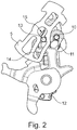
- the clutch lever 3 in turn has a in the FIG. 2 better visible pin 10, with which the clutch lever 3 engages in the control cam 11 of the control lever 4.
- the actuating lever 2 thus takes the control lever 4 with it.
- a spring element 12 acts between the actuating lever 2 and the control lever 4.
- the spring element 12 holds the Control lever 4 in its initial position, so that acts on a relative movement between the actuating lever 2 and the control lever 4, the spring element with a relative force between the control lever 4 and the actuating lever 2.
- the spring force of the spring element which may be in particular a coil spring to overcome.
- the control lever 4 acts again by means of a guide pin 13 with the inertia lever 5 together.
- the guide pin 13 engages in a control cam 14 of the inertia lever 5 a.
- the guide pin 13 in the control curve can be guided radially outwards.
- the inertia lever 5 is pivotally received in the lock 1 about its axis 15.
- the inertia lever 5 preferably has a relation to the axis 15 related balanced mass distribution.
- the inertia lever 5 is mass-balanced about the axis 15.
- a balanced mass balance with respect to the axis 15 has the advantage that no natural oscillations due to vibration in the motor vehicle can arise or can be largely prevented.
- the clutch lever 3 Upon actuation of the operating lever 2, therefore, the clutch lever 3 is operated, and in the case where the operating lever is operated at a normal speed, the control lever 4 follows the movement of the operating lever 2. As a result, the clutch lever 3 is oriented in FIG the functional unit 8 maintains. A radial end 16 of the clutch lever 3 then comes with a stop edge 17 of the trigger lever 6 into engagement. Such engagement between the radial end 16 of the clutch lever 3 with the stop edge 17 is in the FIG. 3 reproduced as normal operation of the castle.
- the release lever 6 Upon actuation of the trigger lever 6, as shown in the FIG. 3 is shown, the release lever 6 performs a movement in the direction of the arrow P2, whereby a trigger arm 18 engages with the pawl 7, for example. The pawl 7 is then moved in the direction of the arrow P3, so that the locking mechanism is unlocked.
- an engagement means 20 which is formed in this embodiment as an extension 20. If, for example, an unillustrated lever is brought into engagement with the extension 20 in the lock 1, the lever, not shown, exerting a force F on the extension 20, the control lever 4 likewise remains in its initial position. The persistence of the control lever 4 in its initial position thereby causes, upon actuation of the actuating lever 2, the clutch lever 3 in the Control cam 11 of the control lever 4 is guided and thus the clutch lever 3 is disengaged from the release lever 6. Thus, the lock 1 is lockable.
Description
Die Erfindung betrifft ein Schloss für ein Kraftfahrzeug, insbesondere ein Seitentürschloss, umfassend ein Gesperre, einen Auslösehebel, einen Betätigungshebel und einen Kupplungshebel, wobei der Auslösehebel mittels des Kupplungshebels mit dem Betätigungshebel kuppelbar ist und einem Mittel zum Steuern des Kupplungshebels.The invention relates to a lock for a motor vehicle, in particular a side door lock comprising a locking mechanism, a release lever, an actuating lever and a clutch lever, wherein the release lever is coupled by means of the coupling lever with the actuating lever and a means for controlling the clutch lever.
Ein Schloss für ein Kraftfahrzeug, das auch Schließsystem genannt wird, werden zum größten Teil Gesperre eingebaut, die aus einer Drehfalle und zumindest einer Sperrklinke bestehen. Das Gesperre im Schloss wirkt dabei mit einem Schlosshalter zusammen, der entweder an der Karosserie des Kraftfahrzeugs oder der Tür, Klappe, Schiebetür, etc. befestigt ist. Die Relativbewegung zwischen Schlosshalter und Drehfalle bewirkt dabei, dass die Drehfalle verschwenkt wird, und gleichzeitig die Sperrklinke mit der Drehfalle in Eingriff gelangt.A lock for a motor vehicle, which is also called locking system, are mostly installed locking mechanism consisting of a catch and at least one pawl. The locking mechanism in the lock acts together with a lock holder, which is attached either to the body of the motor vehicle or the door, flap, sliding door, etc. The relative movement between the lock holder and catch thereby causes the catch to be pivoted, and at the same time the pawl engages with the catch.
Je nach Ausführungsform gibt es ein- oder zweistufige Gesperre, die dann eine Vorrast- und/oder eine Hauptrastposition aufweisen. Die Sperrklinke wird dabei bevorzugt federvorgespannt mit der Drehfalle in Eingriff gebracht. Zum Entsperren, das heißt zum Lösen der Sperrklinke von der Drehfalle wird ein Auslösehebel eingesetzt. Dabei wird die Sperrklinke derart vom Auslösehebel beaufschlagt, dass die Sperrklinke außer Eingriff mit der Drehfalle gelangt und die Drehfalle sich von der Rastposition in eine Öffnungsposition bewegt. Die Bewegung der Drehfalle erfolgt hierbei zumeist mittels eines Federelementes und/oder aufgrund einer Zugbelastung, die aus dem Schlosshalter in Kombination mit der Türdichtung resultiert.Depending on the embodiment, there are one or two-stage locking mechanism, which then have a pre-locking and / or a main locking position. The pawl is preferably spring biased into engagement with the catch. To unlock, that is to release the pawl of the catch a release lever is used. In this case, the pawl is acted upon by the release lever, that the pawl is disengaged from the catch and the catch moves from the detent position to an open position. The movement of the catch is usually done by means of a spring element and / or due to a tensile load resulting from the lock holder in combination with the door seal.
Zum Betätigen des Auslösehebels wird ein Betätigungshebel eingesetzt. Der Betätigungshebel kann beispielsweise ein Innenbetätigungshebel oder ein Außenbetätigungshebel sein. Mit Hilfe des Betätigungshebels wird der Auslösehebel bewegt und das Gesperre entsperrt.For actuating the release lever, an actuating lever is used. The operating lever may be, for example, an inside operating lever or an outside operating lever his. With the help of the operating lever, the release lever is moved and unlocks the locking mechanism.
Zur Erhöhung der Sicherheit in Kraftfahrzeugen kommen Systeme zum Einsatz, die mit Massenträgheitselementen ausgestattet sind. Dabei wirken die Massenträgheitselemente einem externen Impuls entgegen und verhindern dabei, dass zum Beispiel eine Seitentür eines Kraftfahrzeugs unbeabsichtigt geöffnet wird. Ein Impuls kann beispielsweise durch einen Zusammenstoß in das Fahrzeug eingeleitet werden. Wird beispielsweise bei einem Seitenaufprall ein Impuls in das Kraftfahrzeug derart eingeleitet, dass zum Beispiel ein Türgriff einer Seitentür beschleunigt wird, so kann die Auslenkung des Türgriffs bewirken, dass der Betätigungshebel aktiviert wird und das Gesperre öffnet, wodurch es zu einem unbeabsichtigten Öffnen der Seitentür kommen kann. Um derartige ungewollte Ereignisse zu verhindern, sind massenträgheitsbasierte Schließsystem bekannt geworden, die die einem unbeabsichtigten Öffnen eines Türschlosses entgegenwirken.To increase safety in motor vehicles systems are used, which are equipped with inertia elements. In this case, the inertia elements counteract an external impulse and thereby prevent, for example, a side door of a motor vehicle from being inadvertently opened. An impulse may be introduced, for example, by a collision in the vehicle. If, for example, a pulse is introduced into the motor vehicle in a side impact such that, for example, a door handle of a side door is accelerated, the deflection of the door handle can cause the actuating lever to be activated and the locking mechanism to open, which leads to unintentional opening of the side door can. To prevent such unwanted events, mass inertia-based locking system have become known, which counteract the unintentional opening of a door lock.
Aus der
Darüber hinaus ist aus der
Kommt es im Falle eines Unfalls zu einer Betätigung des Betätigungshebels mit einer Betätigungsgeschwindigkeit oberhalb einer bestimmten Grenzgeschwindigkeit, so führt der Betätigungshebel wegen des trägheitsbedingt verzögerten Einkuppelns der Kupplungsanordnung einen Leerhub aus.If, in the event of an accident, an actuation of the actuating lever occurs at an actuating speed above a certain limit speed, then the actuating lever executes an idle stroke due to the inertia-related delayed engagement of the clutch arrangement.
Aus der
Ein weiteres massenträgheitsbasiertes Sließsystem in einem Schloss für ein Kraftfahrzeug mit einem separaten Massenträgheitselement ist aus der
Im Falle einer Überschreibung einer Grenzgeschwindigkeit der Betätigung des Betätigungshebels wirkt ein Sperrhebel auf das Kupplungsglied, so dass das Kupplungsglied außer Eingriff mit dem Auslösehebel gelangt. Der Sperrhebel wiederum liegt federvorgespannt am Auslösehebel an und kann der Bewegung des Betätigungshebels folgen, wenn der Betätigungshebel mit einer normalen Betätigungsgeschwindigkeit betätigt wird. Im Falle eines Unfalls und somit einer überhöhten Geschwindigkeit des Betätigungshebels kann der Steuerhebel durch den mit dem Steuerhebel im Eingriff befindlichen Massenträgheitselement der Bewegung des Betätigungshebels nicht folgen und gelangt mit dem Kupplungshebel in Eingriff. Der Steuerhebel bewirkt dann, dass der Kupplungshebel ausgelenkt wird. Ein Verriegeln des Auslösemechanismusses für das Schloss kann hierbei dadurch erfolgen, dass beispielsweise das Massenträgheitselement im ausgelenkten Zustand, in dem der Steuerhebel mit dem Kupplungshebel in Eingriff ist, fixiert wird, so dass auch bei einem weiteren Betätigen des Betätigungshebels kein Entsperren des Gesperres erfolgen kann.In case of overriding a limit speed of the operation of the operating lever, a locking lever acts on the coupling member, so that the coupling member is disengaged from the release lever. The locking lever in turn is spring biased on the trigger and can the movement of the operating lever when the operating lever is operated at a normal operating speed. In the event of an accident, and thus an excessive speed of the operating lever, the control lever can not follow the movement of the actuating lever by the mass-engagement element engaged with the control lever and engages with the clutch lever. The control lever then causes the clutch lever is deflected. A locking of the trigger mechanism for the lock can in this case take place in that, for example, the inertia element in the deflected state in which the control lever is engaged with the clutch lever, is fixed, so that even with a further actuation of the actuating lever unlocking of the locking mechanism can not take place.
Aus der
Die aus dem Stand der Technik bekannten Sicherungssysteme basieren zumeist darauf, dass das Kupplungsglied mittels eines Federelementes gesteuert wird. Federelemente können bedingt durch Werkstoffeigenschaften und Herstellungsverfahren starke Schwankungen in den Federkonstanten aufweisen. Eine definierte Auslegung der Federn bedarf daher einem großen Aufwand. Darüber hinaus ist ein Steuern mittels eines Federelements auch stets mit Unsicherheiten verbunden, da auch zum Beispiel Temperaturschwankungen die Federeigenschaften beeinflussen können.The safety systems known from the prior art are usually based on the fact that the coupling member is controlled by means of a spring element. Spring elements can have strong fluctuations in the spring constants due to material properties and manufacturing processes. A defined interpretation of the springs therefore requires a lot of effort. In addition, a control by means of a spring element is always associated with uncertainties, as well as, for example, temperature fluctuations can affect the spring properties.
Aufgabe der Erfindung ist es, ein massenträgheitsbasiertes Betätigungssystem für ein Schloss eines Kraftfahrzeugs bereitzustellen, mit dem eine definierte Steuerung des Kupplungsverhaltens in einem Betätigungssystem einer Schließeinrichtung eines Kraftfahrzeugschlosses bereitgestellt werden kann. Aufgabe der Erfindung ist es, ein verbessertes Schloss für ein Kraftfahrzeug bereitzustellen. Darüber hinaus ist es Aufgabe der Erfindung, eine konstruktiv einfache und kostengünstige Möglichkeit zur Sicherung eines Schlosses im Falle eines Unfalls bereitzustellen.The object of the invention is to provide a mass inertia-based actuation system for a lock of a motor vehicle, with which a defined control of the clutch behavior in an actuation system of a locking device a motor vehicle lock can be provided. The object of the invention is to provide an improved lock for a motor vehicle. Moreover, it is an object of the invention to provide a structurally simple and inexpensive way to secure a lock in the event of an accident.
Die Lösung der Aufgabe erfolgt erfindungsgemäß durch die Merkmale des unabhängigen Patentanspruchs 1. Vorteilhafte Ausgestaltungen der Erfindung sind in den Unteransprüchen angegeben.The object is achieved by the features of independent claim 1. Advantageous embodiments of the invention are specified in the dependent claims.
Die Erfindung geht aus von einem Schloss für ein Kraftfahrzeug, insbesondere ein Seitentürschloss, umfassend ein Gesperre, einen Auslösehebel, einen Betätigungshebel, einen Kupplungshebel, wobei der Auslösehebel mittels des Kupplungshebels mit dem Betätigungshebel kuppelbar ist, einen Steuerhebel zum Führen des Kupplungshebels, der zumindest mit dem Betätigungshebel in einer gemeinsamen Achse gelagert ist, einen Massenträgheitshebel, der eine Steuerkontur zum Führen des Steuerhebel aufweist, und eine Steuerkontur zum Führen des Steuerhebel, und eine Steuerkurve als Mittel zum Steuern des Kupplungshebels. Erfindungsgemäß wird vorgeschlagen, dass der Steuerhebel ein Eingriffsmittel, insbesondere eine Verlängerung aufweist, wobei bei einer Betätigung des Eingriffsmittels der Kupplungshebel außer Eingriff mit dem Auslösehebel bringbar ist. Durch die Steuerkurve als Mittel zum Steuern des Kupplungshebels ist nun die Möglichkeit geschaffen, den Kupplungshebel unabhängig vom Eingriff mit einem Federelement zu führen und somit eine definierte Bewegung des Kupplungshebels zwangsweise herbeizuführen.The invention relates to a lock for a motor vehicle, in particular a side door lock, comprising a locking mechanism, a release lever, an actuating lever, a clutch lever, wherein the release lever is coupled by means of the clutch lever with the actuating lever, a control lever for guiding the clutch lever, at least with the control lever is mounted in a common axis, an inertia lever having a control contour for guiding the control lever, and a control contour for guiding the control lever, and a control cam as means for controlling the clutch lever. According to the invention it is proposed that the control lever has an engagement means, in particular an extension, wherein upon actuation of the engagement means, the clutch lever can be brought out of engagement with the release lever. By the control cam as means for controlling the clutch lever, the possibility is now provided to guide the clutch lever regardless of engagement with a spring element and thus forcibly bring about a defined movement of the clutch lever.
Eine Zwangsführung des Kupplungshebels beinhaltet eine definierte Lageregelung des Kupplungshebels zu jedem Zeitpunkt, was wiederum ein hohes Maß an Sicherheit und Funktionalität beinhaltet. Insbesondere können durch eine Zwangsführung des Kupplungshebels in einer Steuerkurve große Kräfte übertragen werden, so dass auch bei einem langsamen aber mit hoher Kraft ausgeführten Betätigung des Betätigungshebels es nicht zu einer Fehlfunktion kommen kann. Insbesondere ist das Kupplungsglied zu jedem Zeitpunkt in einer definierten Position und durch die Ausbildung der Steuerkurve an die unterschiedlichen Einsatzgebiete des Schlosses im Kraftfahrzeug anpassbar.A positive guidance of the clutch lever includes a defined position control of the clutch lever at any time, which in turn includes a high level of safety and functionality. In particular, large forces can be transmitted by a positive guidance of the clutch lever in a control cam, so that even with a slow but executed with high force actuation of the actuating lever, it can not lead to malfunction. In particular, the coupling member at any time in a defined position and by the formation of the control cam to the different applications of the lock in the motor vehicle adaptable.
Das Schloss für ein Kraftfahrzeug umfasst auch solche Schlösser, die zum Beispiel in Schiebetüren, Heckschlössern, Seitentüren, Klappen oder auch Abdeckungen, wie beispielsweise einer Verdeckhaube, zum Einsatz kommen. Dabei umfasst das Schloss üblicherweise ein Gesperre bestehend aus einer Drehfalle und zumindest einer Sperrklinke. Das Gesperre kann dabei mit einer Vorrast und/oder einer Hauptrast ausgebildet sein, wobei ein oder zwei Sperrklinken zum Einsatz kommen können.The lock for a motor vehicle also includes such locks, which are used for example in sliding doors, rear locks, side doors, flaps or covers, such as a hood. In this case, the lock usually comprises a locking mechanism consisting of a catch and at least one pawl. The locking mechanism can be formed with a pre-rest and / or a main catch, with one or two pawls can be used.
Ein Auslösehebel ist der Hebel, der unmittelbar auf das Gesperre einwirkt. Dabei wirkt der Auslösehebel auf die Sperrklinke und löst die Sperrklinke aus dem Eingriff mit der Drehfalle. Zwischen dem Betätigungshebel und dem Auslösehebel wirkt ein Kupplungshebel. Bei einem Betätigen des Betätigungshebels und vorzugsweise des Außenbetätigungshebels kommt der Kupplungshebel mit dem Auslösehebel in Kontakt und ermöglicht somit ein Betätigen des Auslösehebels, wodurch das Gesperre entsperrbar ist. Dabei wird der Kupplungshebel in einer Steuerkurve geführt, so dass eine definierte Ausrichtung des Kupplungshebels auf den Auslösehebel ermöglichbar ist. Einerseits kann die Ausrichtung des Kupplungshebels gesteuert werden, darüber hinaus kann auch das Auslenkungsverhalten des Kupplungshebels durch Verlauf der Kontur eingestellt werden. Dabei ist es möglich, den Auslenkungswinkel wie auch die Auslenkgeschwindigkeit des Kupplungshebels durch den Verlauf der Kontur zu steuern. Je nach vorhandenem Weg beim Betätigen des Betätigungshebels kann somit die Bewegung des Kupplungshebels einstellbar sein.A trigger is the lever that acts directly on the ratchet. The release lever acts on the pawl and releases the pawl from engagement with the catch. Between the operating lever and the trigger lever acts a clutch lever. Upon actuation of the actuating lever and preferably of the external actuating lever, the clutch lever comes into contact with the trigger lever and thus enables actuation of the trigger lever, whereby the locking mechanism can be unlocked. In this case, the clutch lever is guided in a control cam, so that a defined orientation of the clutch lever on the release lever is possible. On the one hand, the orientation of the coupling lever can be controlled, in addition, the deflection behavior of the coupling lever can be adjusted by the contour of the contour. It is possible, the deflection angle as well as the deflection speed of the clutch lever through the course of the contour control. Depending on the existing way when operating the operating lever can thus be adjustable, the movement of the clutch lever.
Der Kupplungshebel ist schwenkbar im Betätigungshebel gelagert. Die Aufnahme des Kupplungshebels im Betätigungshebel und insbesondere im Außenbetätigungshebel bietet den Vorteil, dass mit einer geringen Anzahl von Bauteilen ein Kuppeln des Betätigungshebels mit dem Auslösehebel ermöglichbar ist. Darüber hinaus ist die Übertragung der Bewegung vom Betätigungshebel auf den Auslösehebel unmittelbar möglich. Die schwenkbewegliche Lagerung des Kupplungshebels im Betätigungshebel ermöglicht es hierbei, dass der Kupplungshebel einerseits im Betätigungshebel lagerbar und gleichzeitig durch die Steuerkurve führbar ist.The clutch lever is pivotally mounted in the operating lever. The inclusion of the coupling lever in the actuating lever and in particular in the external actuating lever has the advantage that with a small number of components, a coupling of the actuating lever with the trigger lever is possible. In addition, the transmission of the movement from the actuating lever to the trigger is directly possible. The pivotable mounting of the clutch lever in the operating lever makes it possible here that the clutch lever on the one hand in the operating lever can be stored and simultaneously guided by the control cam.
Dadurch, dass der Steuerhebel den Kupplungshebel führt, werden weitere Vorteile erzielt. Die Aufnahme des Kupplungshebels bzw. das Führen des Kupplungshebels in einem Steuerhebel ermöglicht es hierbei, dass die Steuerkurve den Bewegungen des Betätigungshebels folgen kann. Die Steuerkurve ist somit gemeinsam mit dem Betätigungshebel und im Eingriff mit dem Kupplungshebel gemeinsam mit dem Kupplungshebel bewegbar. Aus dieser Anordnung wird ersichtlich, dass der Steuerhebel als Steuerglied fungieren kann, wenn der Steuerhebel eine Relativbewegung zum Betätigungshebel vollführt.The fact that the control lever leads the clutch lever, further advantages are achieved. The inclusion of the clutch lever or the guiding of the clutch lever in a control lever makes it possible here that the control cam can follow the movements of the actuating lever. The control cam is thus movable together with the actuating lever and in engagement with the clutch lever together with the clutch lever. From this arrangement, it can be seen that the control lever can act as a control member when the control lever performs a relative movement to the actuating lever.
Bei einer normalen Betätigung des Betätigungshebels folgt der Steuerhebel durch den Eingriff einer Feder zwischen Betätigungshebel und Steuerhebel der Bewegung des Betätigungshebels. Der Kupplungshebel ist im Betätigungshebel gelagert und folgt der Bewegung des Betätigungshebels. Wird der Betätigungshebel im Normalbetrieb mit einer der Betätigung zuordbaren Geschwindigkeit bewegt, so folgt der Steuerhebel der Bewegung des Betätigungshebels. Die zwischen dem Steuerhebel und dem Betätigungshebel wirkende Feder ist so ausgelegt, dass eine übereinstimmende Bewegung zwischen Steuerhebel und Betätigungshebel im Normalbetrieb erfolgt.In a normal operation of the operating lever of the control lever follows by the engagement of a spring between the actuating lever and the control lever of the movement of the actuating lever. The clutch lever is mounted in the operating lever and follows the movement of the operating lever. If the operating lever is moved in normal operation with a speed assignable to the operation, then the control lever follows the movement of the actuating lever. The acting between the control lever and the actuating lever spring is designed so that a coincident movement between the control lever and the operating lever is carried out in normal operation.
Lediglich im Falle einer überhöhten Geschwindigkeit des Betätigungshebels, wie sie beispielsweise im Falle eines Unfalls erfolgen kann, wird der Betätigungshebel derart start beschleunigt, dass es zu einer Relativbewegung zwischen Steuerhebel und Betätigungshebel kommt. Eine Relativbewegung zwischen Steuerhebel und Betätigungshebel bedingt dann, dass der Kupplungshebel in der Steuerkurve des Steuerhebels geführt und durch die Geometrie der Kontur des Steuerhebels auslenkbar ist. Das Auslenken des Kupplungshebels bedingt hierbei, dass der Kupplungshebel außer Eingriff mit dem Auslösehebel gelangt. Das Gesperre bleibt gesperrt.Only in the case of an excessive speed of the actuating lever, as may occur, for example, in the event of an accident, the actuating lever is accelerated start so that there is a relative movement between the control lever and the operating lever. A relative movement between the control lever and the actuating lever then requires that the coupling lever is guided in the control cam of the control lever and can be deflected by the geometry of the contour of the control lever. The deflection of the clutch lever in this case causes the clutch lever disengaged from the release lever. The lock remains locked.
Ein weiterer Vorteil wird dadurch erzielt, dass der Steuerhebel zumindest mit dem Betätigungshebel, insbesondere ein Außenbetätigungshebel, in einer gemeinsamen Achse gelagert ist. Eine gemeinsame Lagerung des Steuerhebels und des Betätigungshebels ermöglicht eine konstruktiv günstige Auslegung, die einen geringen Platzbedarf benötigt. Darüber hinaus sind durch die gemeinsamen Lagerungen die Betätigungswege und Hebelmomente leicht aufeinander abstimmbar. Insbesondere die zu übertragenden Momente, die einerseits zum Auslösen des Gesperres benötigt werden und darüber hinaus ein Steuern der Bewegung des Kupplungshebels zur Verfügung gestellt werden können, sind leicht einstellbar.Another advantage is achieved in that the control lever is mounted at least with the actuating lever, in particular an external operating lever, in a common axis. A common storage of the control lever and the actuating lever allows a structurally favorable design, which requires a small footprint. In addition, the actuating paths and lever moments are easily matched to each other by the common bearings. In particular, the moments to be transmitted, which are required on the one hand to trigger the locking mechanism and, moreover, control the movement of the clutch lever can be made available, are easily adjustable.
Der Steuerhebel wirkt mit einem Massenträgheitshebel zusammen, wodurch weitere Vorteile erreicht werden. Ein Massenträgheitshebel ist ein Hebel, der schwenkbar gelagert im Kraftfahrzeugschloss aufgenommen ist und einem Impuls aus einem Unfall entgegenwirkt. Dabei ist das Massenträgheitselement bevorzugt als Hebel ausgebildet und mittig gelagert. Dabei kann eine symmetrische Lastverteilung um den Schwenkpunkt vorteilhaft sein. Der Steuerhebel ist mit dem Massenträgheitshebel unmittelbar im Eingriff. Wie bereits vorstehend erläutert, kommt es bei einer Relativbewegung zwischen dem Betätigungshebel und dem Steuerhebel zu einer Auslenkung des Kupplungshebels. Durch die träge Masse des Massenträgheitshebels wird der Steuerhebel in seinem Trägheitsverhalten unterstützt, so dass eine weitere Sicherheit gegeben ist, um im Falle eines Unfalls den Steuerhebel in seiner Position zu halten. Wirkt dabei der Massenträgheitshebel dem Impuls des Aufschlags entgegen, so verharrt der Massenträgheitshebel in seiner Position und hält den Steuerhebel entgegen der Auslenkung des Betätigungshebels bzw. Außenbetätigungshebels in seiner Ausgangsstellung. Somit wird lediglich der Betätigungshebel durch zum Beispiel einen bewegten Türgriff ausgelenkt und der Steuerhebel verharrt in seiner Ausgangsstellung. Bei einem Betätigen des Betätigungshebels folgt der Kupplungshebel durch seine Lagerung im Betätigungshebel der Bewegung des Betätigungshebels, wobei der Kupplungshebel durch die Steuerkurve des Steuerhebels geführt wird und entsprechend auslenkbar ist. Das Betätigen des Betätigungshebels im Unfallfalle hat somit keine Auswirkung auf den Auslösehebel, so dass das Schloss auch im Falle eines Unfalls geschlossen bleibt.The control lever cooperates with a mass inertia lever, whereby further advantages are achieved. A mass inertia lever is a lever which is pivotally mounted in the motor vehicle lock and counteracts a pulse from an accident. In this case, the inertia element is preferably designed as a lever and mounted centrally. In this case, a symmetrical load distribution around the pivot point can be advantageous. The control lever is directly engaged with the inertia lever. As already explained above, there is a relative movement between the actuating lever and the control lever to a deflection of the clutch lever. By the inertial mass of the inertia lever, the control lever is supported in its inertia behavior, so that further security is given to keep the control lever in case of an accident in its position. If the mass inertia lever counteracts the impulse of the impact, the inertia lever remains in its position and holds the control lever counter to the deflection of the actuating lever or the external actuating lever in its initial position. Thus, only the actuating lever is deflected by, for example, a moving door handle and the control lever remains in its initial position. Upon actuation of the actuating lever of the clutch lever follows by its storage in the operating lever, the movement of the actuating lever, wherein the clutch lever is guided by the control cam of the control lever and is deflected accordingly. The actuation of the operating lever in the event of an accident thus has no effect on the release lever, so that the lock remains closed even in the event of an accident.
Der Massenträgheitshebel weist eine Steuerkontur zum Führen des Steuerhebels auf, wodurch sich sich eine vorteilhafte konstruktive Lösung ergibt, die mit einer minimalen Anzahl an Bauteilen ausgestattet ist. Darüber hinaus ist es vorteilhaft, wenn der Steuerhebel derart in die Kontur des Massenträgheitshebels eingreift, dass ein Angriffspunkt des Steuerhebels in die Steuerkontur nah am Schwenkpunkt des Massenträgheitshebels angeordnet ist. Durch einen Angriffspunkt bzw. eine Führung des Steuerhebels im Massenträgheitshebel in der Nähe des Schwenkpunktes des Massenträgheitshebels steht dem Steuerhebel eine hohe Massenträgheit im Falle eines Unfalls entgegen. Insbesondere in dem Fall, in dem eine symmetrische Massenverteilung um den Drehpunkt des Massenträgheitshebels vorliegt, kann im Falle eines Unfalls der Massenträgheitshebel dem Steuerhebel ein maximales Trägheitsmoment entgegenstellen. In vorteilhafter Weise erstreckt sich die Steuerkontur von einem etwa mittig gelegenen Schwenkpunkt des Massenträgheitshebels bis ein radiales Ende des Massenträgheitshebels. Hierdurch ergibt sich eine weitere vorteilhafte Form der Steuerkontur, da einerseits der Massenträgheitshebel dem Steuerhebel im Falle eines Unfalls ein maximales Trägheitsmoment entgegenstellen kann, wohingegen bei einem normalen Betätigen des Betätigungshebels der Steuerhebel entlang der Steuerkontur im Massenträgheitshebel mit steigender Auslenkung des Betätigungshebels ein geringeres Moment aufbringen muss, um den Massenträgheitshebel auszulenken. Hierdurch wird die Betätigung des Schlosses des Kraftfahrzeuges erleichtert. Die vorteilhafte Ausgestaltung der Steuerkontur entlang der Erstreckung des Massenträgheitshebels wirkt sich somit positiv auf das Verhalten im Unfall und gleichzeitig bei der Normalbetätigung des Schlosses aus.The inertia lever has a control contour for guiding the control lever, resulting in an advantageous constructive solution, which is equipped with a minimum number of components. Moreover, it is advantageous if the control lever engages in the contour of the inertia lever such that a point of application of the control lever is arranged in the control contour close to the pivot point of the inertia lever. By a point of attack or a leadership of the control lever in the inertia lever in the vicinity of the pivot point of the inertia lever, the control lever is a high inertia in the event of an accident. In particular, in the case in which there is a symmetrical mass distribution about the pivot point of the inertia lever, in the case of an accident, the inertia lever can oppose the control lever a maximum moment of inertia. Advantageously, the control contour extends from an approximately centrally located pivot point of the inertia lever to a radial end of the inertia lever. This results in a further advantageous form of Control contour, since on the one hand the inertia lever can oppose the control lever in the event of an accident, a maximum moment of inertia, whereas in a normal operation of the operating lever of the control lever along the control contour in the inertia lever with increasing deflection of the actuating lever has to apply a lesser moment to deflect the inertia lever. As a result, the operation of the lock of the motor vehicle is facilitated. The advantageous embodiment of the control contour along the extension of the inertia lever thus has a positive effect on the behavior in the accident and at the same time in the normal operation of the castle.
Erfindungsgemäß weist der Steuerhebel ein Eingriffsmittel auf, insbesondere einer Verlängerung, wobei bei einer Betätigung des Eingriffsmittels der Kupplungshebel außer Eingriff mit dem Auslösehebel bringbar ist. Der Steuerhebel kann ein Eingriffsmittel aufweisen, in die zum Beispiel ein Zentralverriegelungselement des Schlosses eingreifen kann. In vorteilhafter Weise kann das Eingriffsmittel zum Beispiel als eine Verlängerung ausgebildet sein, die aus dem Steuerhebel herausragt. Das Eingriffsmittel kann aber auch aus einer Öffnung, einer Vertiefung oder einer sonstigen geometrischen Gestaltung ausgebildet sein, in die ein Mittel zur zentralen Verriegelung eingreifen kann und den Steuerhebel in seiner Lage fixiert. Durch das Fixieren des Eingriffsmittels und somit des Steuerhebels kann zwar der Betätigungshebel bzw. der Außenbetätigungshebel betätigt werden, durch das Festhalten bzw. Fixieren des Steuerhebels wird der Kupplungshebel aber durch die Steuerkurve in dem Steuerhebel hindurch bewegt und außer Eingriff mit dem Auslösehebel gebracht. Hierdurch kann mit einfachsten konstruktiven Mitteln ein Verriegelungselement bereitgestellt werden, das auf die vorhandenen Elemente des Schließsystems und insbesondere dem Steuerhebel zugreift. Durch das Positionieren des Steuerhebels ist somit ein Verriegeln ermöglichbar. In vorteilhafter Weise ist das Eingriffsmittel als Verlängerung an den Steuerhebel zum Beispiel einstückig anformbar. Es ist aber selbstverständlich auch vorstellbar, den Steuerhebel in anderer kraftschlüssiger und/oder formschlüssiger Form zu fixieren, so dass ein Bewegen des Steuerhebels unterbindbar ist.According to the invention, the control lever has an engagement means, in particular an extension, wherein upon actuation of the engagement means, the clutch lever can be disengaged from the release lever. The control lever may have an engagement means, in which, for example, a central locking element of the lock can engage. Advantageously, the engagement means may for example be formed as an extension which protrudes from the control lever. However, the engagement means may also be formed from an opening, a recess or other geometric configuration, in which a means for central locking can engage and fixes the control lever in its position. Although the actuating lever or the outer actuating lever can be actuated by the fixing of the engagement means and thus of the control lever, the clutch lever is moved by the control cam in the control lever and disengaged from the trigger lever by the holding or fixing of the control lever. In this way, a locking element can be provided with the simplest structural means, which accesses the existing elements of the locking system and in particular the control lever. By positioning the control lever thus locking is possible. Advantageously, the engagement means as an extension to the control lever, for example, integrally formed. It is of course conceivable, the control lever to fix in another non-positive and / or positive form, so that a movement of the control lever can be prevented.
Ist das Eingriffsmittel elektrisch betätigbar, so ergibt sich eine weitere vorteilhafte Ausgestaltungsform der Erfindung. Eine elektrische Betätigung bietet den Vorteil eines hohen Komforts für den Bediener, so dass der Steuerhebel zum Beispiel im Rahmen einer Zentralverriegelung des Fahrzeugs elektrisch ansteuerbar bzw. positionierbar bzw. fixierbar ist. Dabei kann ein bereits vorhandener Hebel einer Zentralverriegelung zum Eingriff in den Steuerhebel benutzt werden oder es ist ein separater Antrieb vorsehbar.If the engagement means can be actuated electrically, this results in a further advantageous embodiment of the invention. An electrical operation has the advantage of a high level of comfort for the operator, so that the control lever, for example, in the context of a central locking of the vehicle is electrically controlled or positionable or fixable. In this case, an existing lever of a central locking system can be used to engage in the control lever or it is a separate drive providable.
In einer weiteren vorteilhaften Ausführungsform ragt zumindest ein Teil des Kupplungshebels in eine Öffnung des Betätigungshebels hinein und ist in der Öffnung führbar. In einer Normalbetätigung des Betätigungshebels, das heißt bei einer Betätigung des Betätigungshebels mit einer normalen Öffnungsgeschwindigkeit für das Schloss, liegt der Kupplungshebel an einem Ende des Betätigungshebels zum Beispiel federvorgespannt an. Wird nun der Steuerhebel fixiert, das kann einerseits über das Eingriffsmittel und eine Zentralverriegelung oder aber durch das Massenträgheitselement erfolgen, so verfährt der Kupplungshebel in der Steuerkurve des Steuerhebels, wobei der Kupplungshebel verschwenkt wird. Um ein Verschwenken des Kupplungshebels im Betätigungshebel zu ermöglichen, ist der Kupplungshebel in der Öffnung des Betätigungshebels führbar. Das Führen des Kupplungshebels unmittelbar im Betätigungshebel bietet eine weitere Möglichkeit, um eine möglichst konstruktive einfache und somit kostengünstige Möglichkeit zur Führung des Kupplungshebels bei voller Funktionalität zu ermöglichen. Der Aufbau der ineinander greifenden Führungen von Massenträgheitshebel, Steuerhebel, Kupplungshebel und Betätigungshebel bietet eine Vielzahl von Vorteilen für die Funktionalität und bietet gleichzeitig die Möglichkeit, alle funktionalen Vorteile zu nutzen bei geringstmöglicher Anzahl von Bauteilen und konstruktiv günstigem Aufbau.In a further advantageous embodiment, at least part of the coupling lever protrudes into an opening of the actuating lever and can be guided in the opening. In a normal operation of the operating lever, that is, upon actuation of the operating lever with a normal opening speed for the lock, the clutch lever is at one end of the operating lever, for example spring biased on. Now, if the control lever is fixed, which can be done on the one hand on the engagement means and a central locking or by the inertia element, then moves the clutch lever in the control cam of the control lever, wherein the clutch lever is pivoted. In order to enable a pivoting of the clutch lever in the actuating lever, the clutch lever in the opening of the actuating lever is feasible. The guiding of the clutch lever directly in the operating lever offers a further possibility to allow the most constructive simple and thus cost-effective way to guide the clutch lever with full functionality. The construction of the interlocking guides of inertia lever, control lever, clutch lever and operating lever offers a variety of advantages for the functionality and at the same time offers the opportunity to use all functional advantages with the lowest possible number of components and structurally favorable structure.
In einer weiteren vorteilhaften Ausgestaltungsform des Schlosses sind der Betätigungshebel, der Steuerhebel und der Auslösehebel auf einer gemeinsamen Achse und/oder Führung gelagert. Die gemeinsame Aufnahme der Hebel bietet den Vorteil, dass die Funktionseinheit kleinstbauend ausgebildet sein kann, so dass mit minimalem Platz im Schloss des Kraftfahrzeugs ein hohes Maß an Funktionalität realisierbar ist. Dabei können die Hebel auf einer gemeinsamen Achse und/oder einer Führung oder Aufnahme des jeweiligen anderen Hebels aufgenommen oder gelagert sein. Insbesondere bietet die Aufnahme der Hebel auf einer gemeinsamen Achse den Vorteil, dass insbesondere für das Zusammenspiel zum Beispiel zwischen Steuerhebel und Betätigungshebel günstige Eingriffsverhältnisse zum Beispiel für die zwischen dem Steuerhebel und dem Betätigungshebel wirkende Feder.In a further advantageous embodiment of the lock, the actuating lever, the control lever and the release lever are mounted on a common axis and / or guide. The common inclusion of the lever has the advantage that the functional unit can be designed kleinstbauend so that with minimal space in the lock of the motor vehicle, a high degree of functionality can be realized. In this case, the levers may be received or stored on a common axis and / or a guide or receptacle of the respective other lever. In particular, the inclusion of the lever on a common axis has the advantage that, in particular for the interaction, for example, between the control lever and the operating lever favorable engagement conditions, for example, for acting between the control lever and the actuating lever spring.
Nachfolgend wird die Erfindung unter Bezugnahme auf die anliegenden Zeichnungen anhand eines bevorzugten Ausführungsbeispiels näher erläutert. Es gilt jedoch der Grundsatz, dass die Ausführungsbeispiele die Erfindung nicht beschränken, sondern lediglich vorteilhafte Ausgestaltungsformen darstellen. Die dargestellten Merkmale können einzeln oder in Kombination mit weiteren Merkmalen der Beschreibung wie auch den Patentansprüchen einzeln oder in Kombination ausgeführt werden, wobei der Schutzumfang allein durch die anhängigen Ansprüche definiert wird.The invention will be explained in more detail with reference to the accompanying drawings with reference to a preferred embodiment. However, it is the principle that the embodiments do not limit the invention, but represent only advantageous embodiments. The illustrated features may be practiced individually or in combination with other features of the specification as well as the claims, individually or in combination, the scope of which is defined solely by the appended claims.
Es zeigt:
- Figur 1
- eine Vorderansicht auf einen Teil eines Schlosses eines Kraftfahrzeuges mit den zur Erläuterung der Erfindung wesentlichen Bestandteilen. Die Vorderansicht zeigt die Funktionseinheit in einer Ausgangsstellung, das heißt im unbetätigten Zustand,
Figur 2- die Rückansicht der Funktionseinheit gemäß der
Figur 1 im unbetätigten Zustand, das heißt einer Ausgangsstellung, - Figur 3
- eine Vorderansicht auf die Funktionseinheit des Schlosses bei einer normalen Betätigung des Betätigungshebels zum Auslösen des Gesperres, und
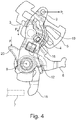
- Figur 4
- eine Vorderansicht auf die Funktionseinheit bei einer stark beschleunigten Bewegung des Betätigungshebels, bei der das Massenträgheitselement ein Auslösen des Gesperres verhindert.
- FIG. 1
- a front view of a part of a lock of a motor vehicle with the essential parts for explaining the invention. The front view shows the functional unit in a starting position, that is in the unactuated state,
- FIG. 2
- the rear view of the functional unit according to the
FIG. 1 in the unactuated state, that is a starting position, - FIG. 3
- a front view of the functional unit of the lock in a normal operation of the actuating lever for triggering the locking mechanism, and
- FIG. 4
- a front view of the functional unit at a greatly accelerated movement of the actuating lever, wherein the inertia element prevents a triggering of the locking mechanism.
In der
Die
Wirkt der Zapfen 10 des Kupplungshebels 3 mit dem Steuerhebel 4 zusammen, so wirkt der Steuerhebel 4 wiederum mittels eines Führungszapfens 13 mit dem Massenträgheitshebel 5 zusammen. Dazu greift der Führungszapfen 13 in eine Steuerkurve 14 des Massenträgheitshebels 5 ein. Wie deutlich in der
Bei einer Betätigung des Betätigungshebels 2 wird folglich der Kupplungshebel 3 betätigt und in dem Fall, in dem der Betätigungshebel mit einer normalen Geschwindigkeit betätigt wird, folgt der Steuerhebel 4 der Bewegung des Betätigungshebels 2. Dies hat zur Folge, dass der Kupplungshebel 3 seine Orientierung in der Funktionseinheit 8 beibehält. Ein radiales Ende 16 des Kupplungshebels 3 kommt dann mit einer Anschlagkante 17 des Auslösehebels 6 in Eingriff. Ein derartiger Eingriff zwischen dem radialen Ende 16 des Kupplungshebels 3 mit der Anschlagkante 17 ist in der
In der
Um den Kupplungshebel 3 außer Eingriff mit dem Auslösehebel 6 zu bringen, weist der Steuerhebel 4 darüber hinaus ein Eingriffsmittel 20 auf, das in dieser Ausführungsform als Verlängerung 20 ausgebildet ist. Wird nun im Schloss 1 zum Beispiel ein nicht dargestellter Hebel mit der Verlängerung 20 in Eingriff gebracht, wobei der nicht dargestellte Hebel eine Kraft F auf die Verlängerung 20 ausübt, so verbleibt der Steuerhebel 4 ebenfalls in seiner Ausgangslage. Das Verharren des Steuerhebels 4 in seiner Ausgangslage bewirkt dabei, dass bei einem Betätigen des Betätigungshebels 2 der Kupplungshebel 3 in der Steuerkurve 11 des Steuerhebels 4 geführt wird und somit der Kupplungshebel 3 außer Eingriff mit dem Auslösehebel 6 gelangt. Somit ist das Schloss 1 verriegelbar.In order to bring the clutch lever 3 out of engagement with the
Wie deutlich in dem Ausführungsbeispiel zu erkennen, werden eine Vielzahl von Vorteilen durch das Ausführungsbeispiel erzielt, wobei lediglich ein geringstmöglicher Platzbedarf erforderlich ist, wobei ein Höchstmaß an Sicherheit durch den Aufbau insbesondere das Einbringen einer Steuerkurve in den Steuerhebel erzielbar ist.As clearly seen in the embodiment, a plurality of advantages are achieved by the embodiment, wherein only a minimum space requirement is required, with the highest level of security through the structure in particular the introduction of a control cam in the control lever is achieved.
- 11
- Schlosslock
- 22
- Betätigungshebelactuating lever
- 33
- Kupplungshebelclutch lever
- 44
- Steuerhebelcontrol lever
- 55
- MassenträgheitshebelInertia lever
- 66
- Auslösehebelsear
- 77
- Gesperre, SperrklinkeLock, pawl
- 88th
- Funktionseinheitfunctional unit
- 99
- Achseaxis
- 1010
- Zapfenspigot
- 1111
- Steuerkurvecam
- 1212
- Federelementspring element
- 1313
- Führungszapfenspigot
- 1414
- Steuerkurvecam
- 1515
- Achseaxis
- 1616
- radiales Enderadial end
- 1717
- Anschlagkantestop edge
- 1818
- Auslösearmrelease arm
- 1919
- Öffnungopening
- 2020
- Eingriffsmittel, VerlängerungEngaging means, extension
- P1, P2, P3, P4P1, P2, P3, P4
- Pfeilarrow
- FF
- Kraftforce
Claims (4)
- Latch (1) for a motor vehicle, especially a side door latch, including a locking mechanism (7), a release lever (6), an operating lever (2), which is designed especially as an outside operating lever, a coupling lever (3), whereby the release lever (6) can be coupled with the operating lever (2) via the coupling lever (3), a control lever (4) for guiding the coupling lever (3), which is at least accommodated with the operating lever (2) in a common axle (9), a mass inertia lever (5), which has a control contour (14) for guiding the control lever (4), and a control curve (11) as a means of controlling the coupling lever (3), characterized by the fact that the coupling lever (3) is accommodated in a pivotable manner in the operating lever (2) and the control lever (4) has an engagement means (20), especially an extension (20) where, upon operating the engagement means (20), the coupling lever (3) can be disengaged from the release lever (6).
- Latch (1) according to claim 1, characterized by the fact that the engagement means (20) can be electrically operated.
- Latch (1) for a motor vehicle according to claim 1 or 2, characterized by the fact that at least one section of the coupling lever (3) protrudes into an aperture (19) of the operating lever (2) and can be guided into the aperture (19).
- Latch (1) for a motor vehicle according to one of the claims 1 to 3, characterized by the fact that the operating lever (2), the control lever (4) and the release lever (6) are accommodated on a common axle (9) and/or a wedge.
Applications Claiming Priority (2)
| Application Number | Priority Date | Filing Date | Title |
|---|---|---|---|
| DE102015118860.0A DE102015118860A1 (en) | 2015-11-04 | 2015-11-04 | Motor vehicle lock |
| PCT/DE2016/100520 WO2017076395A1 (en) | 2015-11-04 | 2016-11-04 | Motor vehicle lock |
Publications (2)
| Publication Number | Publication Date |
|---|---|
| EP3371398A1 EP3371398A1 (en) | 2018-09-12 |
| EP3371398B1 true EP3371398B1 (en) | 2019-07-03 |
Family
ID=57354040
Family Applications (1)
| Application Number | Title | Priority Date | Filing Date |
|---|---|---|---|
| EP16798393.1A Active EP3371398B1 (en) | 2015-11-04 | 2016-11-04 | Motor vehicle lock |
Country Status (6)
| Country | Link |
|---|---|
| US (1) | US11072947B2 (en) |
| EP (1) | EP3371398B1 (en) |
| JP (1) | JP6741760B2 (en) |
| CN (1) | CN108474222B (en) |
| DE (1) | DE102015118860A1 (en) |
| WO (1) | WO2017076395A1 (en) |
Cited By (3)
| Publication number | Priority date | Publication date | Assignee | Title |
|---|---|---|---|---|
| DE102019135230A1 (en) * | 2019-12-19 | 2021-06-24 | Kiekert Aktiengesellschaft | Motor vehicle lock |
| DE102019135228A1 (en) * | 2019-12-19 | 2021-06-24 | Kiekert Aktiengesellschaft | Motor vehicle lock, in particular motor vehicle door lock |
| DE102020133259A1 (en) | 2020-12-14 | 2022-06-15 | Kiekert Aktiengesellschaft | Motor vehicle lock, in particular motor vehicle door lock |
Families Citing this family (16)
| Publication number | Priority date | Publication date | Assignee | Title |
|---|---|---|---|---|
| DE102016112182A1 (en) * | 2016-07-04 | 2018-01-04 | Kiekert Ag | Locking device for a motor vehicle |
| KR20180071434A (en) * | 2016-12-19 | 2018-06-28 | 현대자동차주식회사 | Switchger of tailgate for vehicle |
| DE102017102549A1 (en) | 2017-02-09 | 2018-08-09 | Kiekert Ag | MOTOR VEHICLE LOCK |
| DE102017127386A1 (en) | 2017-11-21 | 2019-05-23 | Kiekert Ag | MOTOR VEHICLE LOCK |
| DE102018101200A1 (en) | 2018-01-19 | 2019-07-25 | Kiekert Ag | MOTOR VEHICLE LOCK |
| DE102018116313A1 (en) * | 2018-04-20 | 2019-10-24 | Kiekert Ag | CASTLE FOR A MOTOR VEHICLE |
| DE102018116325A1 (en) * | 2018-07-05 | 2020-01-09 | Kiekert Ag | Lock for a motor vehicle |
| DE102019108252A1 (en) * | 2019-03-29 | 2020-10-01 | Kiekert Aktiengesellschaft | LOCK FOR A MOTOR VEHICLE |
| DE102019108973A1 (en) * | 2019-04-05 | 2020-10-08 | Kiekert Aktiengesellschaft | MOTOR VEHICLE DOOR LOCK |
| DE102019109581A1 (en) * | 2019-04-11 | 2020-10-15 | Kiekert Aktiengesellschaft | LOCK FOR A MOTOR VEHICLE |
| DE102019134511A1 (en) * | 2019-12-16 | 2021-06-17 | Kiekert Aktiengesellschaft | LOCK FOR A MOTOR VEHICLE |
| DE102019134513A1 (en) * | 2019-12-16 | 2021-06-17 | Kiekert Aktiengesellschaft | LOCK FOR A MOTOR VEHICLE |
| DE102020133257A1 (en) | 2020-12-14 | 2022-06-15 | Kiekert Aktiengesellschaft | Motor vehicle lock, in particular motor vehicle door lock |
| DE102022122495A1 (en) | 2022-09-06 | 2024-03-07 | Kiekert Aktiengesellschaft | Motor vehicle lock, in particular motor vehicle door lock |
| DE102022122496A1 (en) | 2022-09-06 | 2024-03-07 | Kiekert Aktiengesellschaft | Motor vehicle lock |
| DE102022122494A1 (en) | 2022-09-06 | 2024-03-07 | Kiekert Aktiengesellschaft | Motor vehicle lock, in particular motor vehicle door lock |
Family Cites Families (22)
| Publication number | Priority date | Publication date | Assignee | Title |
|---|---|---|---|---|
| JPS56124149U (en) | 1980-02-22 | 1981-09-21 | ||
| JPH0828119A (en) | 1994-05-13 | 1996-01-30 | Nippondenso Co Ltd | Door lock driving device |
| JP3404348B2 (en) * | 2000-02-29 | 2003-05-06 | アイシン精機株式会社 | Vehicle door locking and unlocking device |
| DE10139975A1 (en) * | 2000-09-07 | 2002-04-25 | Bosch Gmbh Robert | Vehicle door lock, with a central locking system, has a linkage which can be operated mechanically from the door handle for normal use and especially in an emergency |
| DE50111505D1 (en) | 2000-09-07 | 2007-01-04 | Brose Schliesssysteme Gmbh | MOTOR VEHICLE DOOR LOCK WITH COMBINED CENTRAL LOCKING AND OPENING DRIVE |
| GB0214817D0 (en) * | 2002-06-27 | 2002-08-07 | Arvinmeritor Light Vehicle Sys | Door latch mechanism |
| DE202008003845U1 (en) * | 2008-03-19 | 2009-08-13 | Kiekert Ag | Door lock unit for a motor vehicle |
| DE202009009061U1 (en) * | 2009-06-30 | 2010-12-09 | Kiekert Ag | Motor vehicle door lock |
| JP5447860B2 (en) * | 2010-03-24 | 2014-03-19 | アイシン精機株式会社 | Vehicle door lock device |
| DE202010011805U1 (en) | 2010-08-25 | 2011-12-05 | Kiekert Ag | Motor vehicle door lock |
| DE102011018512A1 (en) * | 2011-04-23 | 2012-10-25 | Kiekert Ag | Motor vehicle door lock |
| KR101806565B1 (en) * | 2011-12-13 | 2017-12-08 | 현대자동차주식회사 | Apparatus for latching door for vehicle |
| DE202012007312U1 (en) | 2012-07-31 | 2013-11-04 | BROSE SCHLIEßSYSTEME GMBH & CO. KG | Motor vehicle lock arrangement |
| DE202013104118U1 (en) | 2013-09-10 | 2014-12-15 | BROSE SCHLIEßSYSTEME GMBH & CO. KG | Motor vehicle lock |
| DE102013110756A1 (en) * | 2013-09-27 | 2015-04-02 | Kiekert Aktiengesellschaft | Motor vehicle door lock |
| DE102014001490A1 (en) | 2014-01-28 | 2015-07-30 | Kiekert Aktiengesellschaft | Lock for a motor vehicle |
| DE102015002053A1 (en) * | 2014-02-24 | 2015-08-27 | Magna Closures Inc. | Lock for a door of a motor vehicle |
| DE102014002581A1 (en) | 2014-02-26 | 2015-08-27 | Kiekert Aktiengesellschaft | Motor vehicle door lock |
| DE102014004550A1 (en) * | 2014-03-31 | 2015-10-01 | Kiekert Aktiengesellschaft | Actuation device for a motor vehicle lock |
| DE102014004552A1 (en) * | 2014-03-31 | 2015-10-01 | Kiekert Aktiengesellschaft | Actuation device for a motor vehicle lock |
| KR101673685B1 (en) * | 2014-10-28 | 2016-11-07 | 현대자동차주식회사 | Device for preventing opening of door |
| DE102015001906A1 (en) | 2015-02-18 | 2016-08-18 | Kiekert Aktiengesellschaft | Actuation device for a motor vehicle lock |
-
2015
- 2015-11-04 DE DE102015118860.0A patent/DE102015118860A1/en active Pending
-
2016
- 2016-11-04 JP JP2018522937A patent/JP6741760B2/en active Active
- 2016-11-04 CN CN201680077665.XA patent/CN108474222B/en active Active
- 2016-11-04 EP EP16798393.1A patent/EP3371398B1/en active Active
- 2016-11-04 US US15/773,599 patent/US11072947B2/en active Active
- 2016-11-04 WO PCT/DE2016/100520 patent/WO2017076395A1/en active Application Filing
Non-Patent Citations (1)
| Title |
|---|
| None * |
Cited By (4)
| Publication number | Priority date | Publication date | Assignee | Title |
|---|---|---|---|---|
| DE102019135230A1 (en) * | 2019-12-19 | 2021-06-24 | Kiekert Aktiengesellschaft | Motor vehicle lock |
| DE102019135228A1 (en) * | 2019-12-19 | 2021-06-24 | Kiekert Aktiengesellschaft | Motor vehicle lock, in particular motor vehicle door lock |
| DE102020133259A1 (en) | 2020-12-14 | 2022-06-15 | Kiekert Aktiengesellschaft | Motor vehicle lock, in particular motor vehicle door lock |
| WO2022127958A1 (en) | 2020-12-14 | 2022-06-23 | Kiekert Aktiengesellschaft | Motor vehicle lock, in particular motor vehicle door lock |
Also Published As
| Publication number | Publication date |
|---|---|
| JP2018534452A (en) | 2018-11-22 |
| WO2017076395A1 (en) | 2017-05-11 |
| CN108474222B (en) | 2020-05-12 |
| JP6741760B2 (en) | 2020-08-19 |
| EP3371398A1 (en) | 2018-09-12 |
| DE102015118860A1 (en) | 2017-05-04 |
| CN108474222A (en) | 2018-08-31 |
| US11072947B2 (en) | 2021-07-27 |
| US20190078356A1 (en) | 2019-03-14 |
Similar Documents
| Publication | Publication Date | Title |
|---|---|---|
| EP3371398B1 (en) | Motor vehicle lock | |
| DE102017102549A1 (en) | MOTOR VEHICLE LOCK | |
| EP3126600B1 (en) | Actuating device for a motor vehicle lock | |
| EP2673439B1 (en) | Motor vehicle door lock | |
| EP4073335B1 (en) | Motor vehicle lock | |
| EP2999836B1 (en) | Lock for a motor vehicle | |
| WO2018006899A1 (en) | Locking device for a motor vehicle | |
| WO2015127916A1 (en) | Motor vehicle door lock | |
| EP3126599B1 (en) | Actuating device for a motor vehicle lock | |
| EP3947872B1 (en) | Lock for a motor vehicle | |
| DE102009058750A1 (en) | Actuation apparatus for lock of door in motor vehicle, has safety device comprising safety element that is movable from releasing position into safeguard position due to large accidental force admission of device by mass inertia effect | |
| DE102017216920A1 (en) | Door handle device for a door of a motor vehicle, door, motor vehicle | |
| EP3317482B1 (en) | Motor vehicle lock | |
| DE102017103472A1 (en) | Motor vehicle door lock | |
| EP2673438B1 (en) | Motor vehicle door lock | |
| DE102016121735A1 (en) | Lock for a motor vehicle | |
| DE102014001123A1 (en) | Locking device for a motor vehicle | |
| EP3117057B1 (en) | Motor vehicle door lock | |
| DE102017127386A1 (en) | MOTOR VEHICLE LOCK | |
| WO2018086647A1 (en) | Lock for a motor vehicle | |
| DE102014014619A1 (en) | Actuation device for a Kraffahrzeugschloss | |
| EP4097317A1 (en) | Motor vehicle lock | |
| DE102020106126A1 (en) | Motor vehicle lock | |
| EP3953549B1 (en) | Lock for a motor vehicle | |
| WO2017036452A1 (en) | Motor vehicle door lock |
Legal Events
| Date | Code | Title | Description |
|---|---|---|---|
| STAA | Information on the status of an ep patent application or granted ep patent |
Free format text: STATUS: UNKNOWN |
|
| STAA | Information on the status of an ep patent application or granted ep patent |
Free format text: STATUS: THE INTERNATIONAL PUBLICATION HAS BEEN MADE |
|
| PUAI | Public reference made under article 153(3) epc to a published international application that has entered the european phase |
Free format text: ORIGINAL CODE: 0009012 |
|
| STAA | Information on the status of an ep patent application or granted ep patent |
Free format text: STATUS: REQUEST FOR EXAMINATION WAS MADE |
|
| 17P | Request for examination filed |
Effective date: 20180510 |
|
| AK | Designated contracting states |
Kind code of ref document: A1 Designated state(s): AL AT BE BG CH CY CZ DE DK EE ES FI FR GB GR HR HU IE IS IT LI LT LU LV MC MK MT NL NO PL PT RO RS SE SI SK SM TR |
|
| AX | Request for extension of the european patent |
Extension state: BA ME |
|
| DAV | Request for validation of the european patent (deleted) | ||
| DAX | Request for extension of the european patent (deleted) | ||
| GRAP | Despatch of communication of intention to grant a patent |
Free format text: ORIGINAL CODE: EPIDOSNIGR1 |
|
| STAA | Information on the status of an ep patent application or granted ep patent |
Free format text: STATUS: GRANT OF PATENT IS INTENDED |
|
| INTG | Intention to grant announced |
Effective date: 20190423 |
|
| GRAS | Grant fee paid |
Free format text: ORIGINAL CODE: EPIDOSNIGR3 |
|
| GRAA | (expected) grant |
Free format text: ORIGINAL CODE: 0009210 |
|
| STAA | Information on the status of an ep patent application or granted ep patent |
Free format text: STATUS: THE PATENT HAS BEEN GRANTED |
|
| AK | Designated contracting states |
Kind code of ref document: B1 Designated state(s): AL AT BE BG CH CY CZ DE DK EE ES FI FR GB GR HR HU IE IS IT LI LT LU LV MC MK MT NL NO PL PT RO RS SE SI SK SM TR |
|
| REG | Reference to a national code |
Ref country code: GB Ref legal event code: FG4D Free format text: NOT ENGLISH |
|
| REG | Reference to a national code |
Ref country code: CH Ref legal event code: EP Ref country code: AT Ref legal event code: REF Ref document number: 1151187 Country of ref document: AT Kind code of ref document: T Effective date: 20190715 |
|
| REG | Reference to a national code |
Ref country code: DE Ref legal event code: R096 Ref document number: 502016005419 Country of ref document: DE |
|
| REG | Reference to a national code |
Ref country code: IE Ref legal event code: FG4D Free format text: LANGUAGE OF EP DOCUMENT: GERMAN |
|
| REG | Reference to a national code |
Ref country code: NL Ref legal event code: MP Effective date: 20190703 |
|
| REG | Reference to a national code |
Ref country code: LT Ref legal event code: MG4D |
|
| PG25 | Lapsed in a contracting state [announced via postgrant information from national office to epo] |
Ref country code: BG Free format text: LAPSE BECAUSE OF FAILURE TO SUBMIT A TRANSLATION OF THE DESCRIPTION OR TO PAY THE FEE WITHIN THE PRESCRIBED TIME-LIMIT Effective date: 20191003 Ref country code: NL Free format text: LAPSE BECAUSE OF FAILURE TO SUBMIT A TRANSLATION OF THE DESCRIPTION OR TO PAY THE FEE WITHIN THE PRESCRIBED TIME-LIMIT Effective date: 20190703 Ref country code: PT Free format text: LAPSE BECAUSE OF FAILURE TO SUBMIT A TRANSLATION OF THE DESCRIPTION OR TO PAY THE FEE WITHIN THE PRESCRIBED TIME-LIMIT Effective date: 20191104 Ref country code: HR Free format text: LAPSE BECAUSE OF FAILURE TO SUBMIT A TRANSLATION OF THE DESCRIPTION OR TO PAY THE FEE WITHIN THE PRESCRIBED TIME-LIMIT Effective date: 20190703 Ref country code: LT Free format text: LAPSE BECAUSE OF FAILURE TO SUBMIT A TRANSLATION OF THE DESCRIPTION OR TO PAY THE FEE WITHIN THE PRESCRIBED TIME-LIMIT Effective date: 20190703 Ref country code: NO Free format text: LAPSE BECAUSE OF FAILURE TO SUBMIT A TRANSLATION OF THE DESCRIPTION OR TO PAY THE FEE WITHIN THE PRESCRIBED TIME-LIMIT Effective date: 20191003 Ref country code: FI Free format text: LAPSE BECAUSE OF FAILURE TO SUBMIT A TRANSLATION OF THE DESCRIPTION OR TO PAY THE FEE WITHIN THE PRESCRIBED TIME-LIMIT Effective date: 20190703 Ref country code: SE Free format text: LAPSE BECAUSE OF FAILURE TO SUBMIT A TRANSLATION OF THE DESCRIPTION OR TO PAY THE FEE WITHIN THE PRESCRIBED TIME-LIMIT Effective date: 20190703 |
|
| PG25 | Lapsed in a contracting state [announced via postgrant information from national office to epo] |
Ref country code: IS Free format text: LAPSE BECAUSE OF FAILURE TO SUBMIT A TRANSLATION OF THE DESCRIPTION OR TO PAY THE FEE WITHIN THE PRESCRIBED TIME-LIMIT Effective date: 20191103 Ref country code: RS Free format text: LAPSE BECAUSE OF FAILURE TO SUBMIT A TRANSLATION OF THE DESCRIPTION OR TO PAY THE FEE WITHIN THE PRESCRIBED TIME-LIMIT Effective date: 20190703 Ref country code: GR Free format text: LAPSE BECAUSE OF FAILURE TO SUBMIT A TRANSLATION OF THE DESCRIPTION OR TO PAY THE FEE WITHIN THE PRESCRIBED TIME-LIMIT Effective date: 20191004 Ref country code: ES Free format text: LAPSE BECAUSE OF FAILURE TO SUBMIT A TRANSLATION OF THE DESCRIPTION OR TO PAY THE FEE WITHIN THE PRESCRIBED TIME-LIMIT Effective date: 20190703 Ref country code: AL Free format text: LAPSE BECAUSE OF FAILURE TO SUBMIT A TRANSLATION OF THE DESCRIPTION OR TO PAY THE FEE WITHIN THE PRESCRIBED TIME-LIMIT Effective date: 20190703 Ref country code: LV Free format text: LAPSE BECAUSE OF FAILURE TO SUBMIT A TRANSLATION OF THE DESCRIPTION OR TO PAY THE FEE WITHIN THE PRESCRIBED TIME-LIMIT Effective date: 20190703 |
|
| PG25 | Lapsed in a contracting state [announced via postgrant information from national office to epo] |
Ref country code: TR Free format text: LAPSE BECAUSE OF FAILURE TO SUBMIT A TRANSLATION OF THE DESCRIPTION OR TO PAY THE FEE WITHIN THE PRESCRIBED TIME-LIMIT Effective date: 20190703 |
|
| PG25 | Lapsed in a contracting state [announced via postgrant information from national office to epo] |
Ref country code: RO Free format text: LAPSE BECAUSE OF FAILURE TO SUBMIT A TRANSLATION OF THE DESCRIPTION OR TO PAY THE FEE WITHIN THE PRESCRIBED TIME-LIMIT Effective date: 20190703 Ref country code: IT Free format text: LAPSE BECAUSE OF FAILURE TO SUBMIT A TRANSLATION OF THE DESCRIPTION OR TO PAY THE FEE WITHIN THE PRESCRIBED TIME-LIMIT Effective date: 20190703 Ref country code: EE Free format text: LAPSE BECAUSE OF FAILURE TO SUBMIT A TRANSLATION OF THE DESCRIPTION OR TO PAY THE FEE WITHIN THE PRESCRIBED TIME-LIMIT Effective date: 20190703 Ref country code: DK Free format text: LAPSE BECAUSE OF FAILURE TO SUBMIT A TRANSLATION OF THE DESCRIPTION OR TO PAY THE FEE WITHIN THE PRESCRIBED TIME-LIMIT Effective date: 20190703 Ref country code: PL Free format text: LAPSE BECAUSE OF FAILURE TO SUBMIT A TRANSLATION OF THE DESCRIPTION OR TO PAY THE FEE WITHIN THE PRESCRIBED TIME-LIMIT Effective date: 20190703 |
|
| PG25 | Lapsed in a contracting state [announced via postgrant information from national office to epo] |
Ref country code: SK Free format text: LAPSE BECAUSE OF FAILURE TO SUBMIT A TRANSLATION OF THE DESCRIPTION OR TO PAY THE FEE WITHIN THE PRESCRIBED TIME-LIMIT Effective date: 20190703 Ref country code: IS Free format text: LAPSE BECAUSE OF FAILURE TO SUBMIT A TRANSLATION OF THE DESCRIPTION OR TO PAY THE FEE WITHIN THE PRESCRIBED TIME-LIMIT Effective date: 20200224 Ref country code: SM Free format text: LAPSE BECAUSE OF FAILURE TO SUBMIT A TRANSLATION OF THE DESCRIPTION OR TO PAY THE FEE WITHIN THE PRESCRIBED TIME-LIMIT Effective date: 20190703 |
|
| REG | Reference to a national code |
Ref country code: DE Ref legal event code: R097 Ref document number: 502016005419 Country of ref document: DE |
|
| REG | Reference to a national code |
Ref country code: CH Ref legal event code: PL |
|
| PLBE | No opposition filed within time limit |
Free format text: ORIGINAL CODE: 0009261 |
|
| STAA | Information on the status of an ep patent application or granted ep patent |
Free format text: STATUS: NO OPPOSITION FILED WITHIN TIME LIMIT |
|
| PG2D | Information on lapse in contracting state deleted |
Ref country code: IS |
|
| PG25 | Lapsed in a contracting state [announced via postgrant information from national office to epo] |
Ref country code: CH Free format text: LAPSE BECAUSE OF NON-PAYMENT OF DUE FEES Effective date: 20191130 Ref country code: LI Free format text: LAPSE BECAUSE OF NON-PAYMENT OF DUE FEES Effective date: 20191130 Ref country code: MC Free format text: LAPSE BECAUSE OF FAILURE TO SUBMIT A TRANSLATION OF THE DESCRIPTION OR TO PAY THE FEE WITHIN THE PRESCRIBED TIME-LIMIT Effective date: 20190703 Ref country code: LU Free format text: LAPSE BECAUSE OF NON-PAYMENT OF DUE FEES Effective date: 20191104 |
|
| 26N | No opposition filed |
Effective date: 20200603 |
|
| REG | Reference to a national code |
Ref country code: BE Ref legal event code: MM Effective date: 20191130 |
|
| PG25 | Lapsed in a contracting state [announced via postgrant information from national office to epo] |
Ref country code: SI Free format text: LAPSE BECAUSE OF FAILURE TO SUBMIT A TRANSLATION OF THE DESCRIPTION OR TO PAY THE FEE WITHIN THE PRESCRIBED TIME-LIMIT Effective date: 20190703 |
|
| PG25 | Lapsed in a contracting state [announced via postgrant information from national office to epo] |
Ref country code: IE Free format text: LAPSE BECAUSE OF NON-PAYMENT OF DUE FEES Effective date: 20191104 |
|
| PG25 | Lapsed in a contracting state [announced via postgrant information from national office to epo] |
Ref country code: BE Free format text: LAPSE BECAUSE OF NON-PAYMENT OF DUE FEES Effective date: 20191130 |
|
| PG25 | Lapsed in a contracting state [announced via postgrant information from national office to epo] |
Ref country code: CY Free format text: LAPSE BECAUSE OF FAILURE TO SUBMIT A TRANSLATION OF THE DESCRIPTION OR TO PAY THE FEE WITHIN THE PRESCRIBED TIME-LIMIT Effective date: 20190703 |
|
| GBPC | Gb: european patent ceased through non-payment of renewal fee |
Effective date: 20201104 |
|
| PG25 | Lapsed in a contracting state [announced via postgrant information from national office to epo] |
Ref country code: HU Free format text: LAPSE BECAUSE OF FAILURE TO SUBMIT A TRANSLATION OF THE DESCRIPTION OR TO PAY THE FEE WITHIN THE PRESCRIBED TIME-LIMIT; INVALID AB INITIO Effective date: 20161104 Ref country code: MT Free format text: LAPSE BECAUSE OF FAILURE TO SUBMIT A TRANSLATION OF THE DESCRIPTION OR TO PAY THE FEE WITHIN THE PRESCRIBED TIME-LIMIT Effective date: 20190703 |
|
| PG25 | Lapsed in a contracting state [announced via postgrant information from national office to epo] |
Ref country code: GB Free format text: LAPSE BECAUSE OF NON-PAYMENT OF DUE FEES Effective date: 20201104 |
|
| PG25 | Lapsed in a contracting state [announced via postgrant information from national office to epo] |
Ref country code: MK Free format text: LAPSE BECAUSE OF FAILURE TO SUBMIT A TRANSLATION OF THE DESCRIPTION OR TO PAY THE FEE WITHIN THE PRESCRIBED TIME-LIMIT Effective date: 20190703 |
|
| REG | Reference to a national code |
Ref country code: AT Ref legal event code: MM01 Ref document number: 1151187 Country of ref document: AT Kind code of ref document: T Effective date: 20211104 |
|
| PG25 | Lapsed in a contracting state [announced via postgrant information from national office to epo] |
Ref country code: AT Free format text: LAPSE BECAUSE OF NON-PAYMENT OF DUE FEES Effective date: 20211104 |
|
| P01 | Opt-out of the competence of the unified patent court (upc) registered |
Effective date: 20230529 |
|
| PGFP | Annual fee paid to national office [announced via postgrant information from national office to epo] |
Ref country code: FR Payment date: 20231123 Year of fee payment: 8 Ref country code: DE Payment date: 20231120 Year of fee payment: 8 Ref country code: CZ Payment date: 20231023 Year of fee payment: 8 |