EP3349807B1 - Hybride silikon- und acrylklebeabdeckung zur verwendung bei der wundbehandlung - Google Patents
Hybride silikon- und acrylklebeabdeckung zur verwendung bei der wundbehandlung Download PDFInfo
- Publication number
- EP3349807B1 EP3349807B1 EP16781592.7A EP16781592A EP3349807B1 EP 3349807 B1 EP3349807 B1 EP 3349807B1 EP 16781592 A EP16781592 A EP 16781592A EP 3349807 B1 EP3349807 B1 EP 3349807B1
- Authority
- EP
- European Patent Office
- Prior art keywords
- adhesive layer
- layer
- adhesive
- cover
- film layer
- Prior art date
- Legal status (The legal status is an assumption and is not a legal conclusion. Google has not performed a legal analysis and makes no representation as to the accuracy of the status listed.)
- Active
Links
- 229920001296 polysiloxane Polymers 0.000 title claims description 42
- 239000003522 acrylic cement Substances 0.000 title description 32
- 206010052428 Wound Diseases 0.000 title description 14
- 208000027418 Wounds and injury Diseases 0.000 title description 14
- 239000013464 silicone adhesive Substances 0.000 title description 12
- 239000012790 adhesive layer Substances 0.000 claims description 420
- 239000010410 layer Substances 0.000 claims description 358
- 239000000853 adhesive Substances 0.000 claims description 75
- 230000001070 adhesive effect Effects 0.000 claims description 75
- 238000002560 therapeutic procedure Methods 0.000 claims description 58
- 238000000576 coating method Methods 0.000 claims description 43
- 238000010168 coupling process Methods 0.000 claims description 43
- 238000005859 coupling reaction Methods 0.000 claims description 43
- 230000008878 coupling Effects 0.000 claims description 42
- 239000011248 coating agent Substances 0.000 claims description 41
- 238000004519 manufacturing process Methods 0.000 claims description 39
- 238000000034 method Methods 0.000 claims description 30
- 238000002835 absorbance Methods 0.000 claims description 25
- 238000004513 sizing Methods 0.000 claims description 24
- 238000007789 sealing Methods 0.000 claims description 17
- 238000002834 transmittance Methods 0.000 claims description 13
- 238000002844 melting Methods 0.000 claims description 11
- 230000008018 melting Effects 0.000 claims description 11
- 238000005266 casting Methods 0.000 claims description 6
- 239000003054 catalyst Substances 0.000 claims description 5
- 238000005520 cutting process Methods 0.000 claims description 5
- 238000005553 drilling Methods 0.000 claims description 5
- 238000004080 punching Methods 0.000 claims description 5
- BASFCYQUMIYNBI-UHFFFAOYSA-N platinum Chemical compound [Pt] BASFCYQUMIYNBI-UHFFFAOYSA-N 0.000 claims description 4
- NINIDFKCEFEMDL-UHFFFAOYSA-N Sulfur Chemical compound [S] NINIDFKCEFEMDL-UHFFFAOYSA-N 0.000 claims description 2
- 229910052697 platinum Inorganic materials 0.000 claims description 2
- 239000011593 sulfur Substances 0.000 claims description 2
- 229910052717 sulfur Inorganic materials 0.000 claims description 2
- 238000010030 laminating Methods 0.000 claims 2
- 210000001519 tissue Anatomy 0.000 description 115
- 239000012945 sealing adhesive Substances 0.000 description 81
- 239000012530 fluid Substances 0.000 description 46
- 239000000463 material Substances 0.000 description 28
- 239000000499 gel Substances 0.000 description 26
- 210000002615 epidermis Anatomy 0.000 description 25
- 229920006264 polyurethane film Polymers 0.000 description 24
- 239000011800 void material Substances 0.000 description 24
- 230000001225 therapeutic effect Effects 0.000 description 16
- 238000002803 maceration Methods 0.000 description 15
- 239000006260 foam Substances 0.000 description 12
- 239000004814 polyurethane Substances 0.000 description 11
- 238000004132 cross linking Methods 0.000 description 10
- 230000005670 electromagnetic radiation Effects 0.000 description 9
- 229920002635 polyurethane Polymers 0.000 description 9
- 239000007788 liquid Substances 0.000 description 7
- 238000005259 measurement Methods 0.000 description 7
- 230000008569 process Effects 0.000 description 7
- 238000012360 testing method Methods 0.000 description 7
- 230000008901 benefit Effects 0.000 description 6
- 238000009826 distribution Methods 0.000 description 6
- 230000004888 barrier function Effects 0.000 description 5
- 230000007423 decrease Effects 0.000 description 5
- 239000004744 fabric Substances 0.000 description 5
- 239000000017 hydrogel Substances 0.000 description 5
- 230000037361 pathway Effects 0.000 description 5
- 239000011148 porous material Substances 0.000 description 5
- 238000007639 printing Methods 0.000 description 5
- 238000001228 spectrum Methods 0.000 description 5
- 230000010261 cell growth Effects 0.000 description 4
- 238000010276 construction Methods 0.000 description 4
- 239000000416 hydrocolloid Substances 0.000 description 4
- 230000008520 organization Effects 0.000 description 4
- 230000004044 response Effects 0.000 description 4
- 229910001220 stainless steel Inorganic materials 0.000 description 4
- 239000010935 stainless steel Substances 0.000 description 4
- 239000000126 substance Substances 0.000 description 4
- 239000000758 substrate Substances 0.000 description 4
- 238000003466 welding Methods 0.000 description 4
- 229920000954 Polyglycolide Polymers 0.000 description 3
- 239000004372 Polyvinyl alcohol Substances 0.000 description 3
- 230000002238 attenuated effect Effects 0.000 description 3
- 230000005540 biological transmission Effects 0.000 description 3
- 210000000416 exudates and transudate Anatomy 0.000 description 3
- 238000010438 heat treatment Methods 0.000 description 3
- 208000014674 injury Diseases 0.000 description 3
- 230000005865 ionizing radiation Effects 0.000 description 3
- 230000000670 limiting effect Effects 0.000 description 3
- 239000000203 mixture Substances 0.000 description 3
- 239000006072 paste Substances 0.000 description 3
- 239000004633 polyglycolic acid Substances 0.000 description 3
- 239000002861 polymer material Substances 0.000 description 3
- 229920002451 polyvinyl alcohol Polymers 0.000 description 3
- 230000005855 radiation Effects 0.000 description 3
- 230000002829 reductive effect Effects 0.000 description 3
- 238000005096 rolling process Methods 0.000 description 3
- 230000008733 trauma Effects 0.000 description 3
- 239000004952 Polyamide Substances 0.000 description 2
- 239000004820 Pressure-sensitive adhesive Substances 0.000 description 2
- 208000025865 Ulcer Diseases 0.000 description 2
- 229920006397 acrylic thermoplastic Polymers 0.000 description 2
- JEDYYFXHPAIBGR-UHFFFAOYSA-N butafenacil Chemical compound O=C1N(C)C(C(F)(F)F)=CC(=O)N1C1=CC=C(Cl)C(C(=O)OC(C)(C)C(=O)OCC=C)=C1 JEDYYFXHPAIBGR-UHFFFAOYSA-N 0.000 description 2
- 239000004020 conductor Substances 0.000 description 2
- 229920001577 copolymer Polymers 0.000 description 2
- 230000003247 decreasing effect Effects 0.000 description 2
- 238000001514 detection method Methods 0.000 description 2
- 238000011161 development Methods 0.000 description 2
- 230000006870 function Effects 0.000 description 2
- 238000005469 granulation Methods 0.000 description 2
- 230000003179 granulation Effects 0.000 description 2
- 230000012010 growth Effects 0.000 description 2
- 230000002209 hydrophobic effect Effects 0.000 description 2
- 230000003993 interaction Effects 0.000 description 2
- 239000011344 liquid material Substances 0.000 description 2
- 244000005700 microbiome Species 0.000 description 2
- 229920003229 poly(methyl methacrylate) Polymers 0.000 description 2
- 229920002647 polyamide Polymers 0.000 description 2
- 239000004626 polylactic acid Substances 0.000 description 2
- 229920000642 polymer Polymers 0.000 description 2
- 229920000036 polyvinylpyrrolidone Polymers 0.000 description 2
- 239000001267 polyvinylpyrrolidone Substances 0.000 description 2
- 235000013855 polyvinylpyrrolidone Nutrition 0.000 description 2
- 229920002379 silicone rubber Polymers 0.000 description 2
- 210000003491 skin Anatomy 0.000 description 2
- 239000007787 solid Substances 0.000 description 2
- 238000003860 storage Methods 0.000 description 2
- ISXSCDLOGDJUNJ-UHFFFAOYSA-N tert-butyl prop-2-enoate Chemical compound CC(C)(C)OC(=O)C=C ISXSCDLOGDJUNJ-UHFFFAOYSA-N 0.000 description 2
- 230000000699 topical effect Effects 0.000 description 2
- 238000012546 transfer Methods 0.000 description 2
- 231100000397 ulcer Toxicity 0.000 description 2
- 238000001429 visible spectrum Methods 0.000 description 2
- 238000012800 visualization Methods 0.000 description 2
- 235000014653 Carica parviflora Nutrition 0.000 description 1
- 241000243321 Cnidaria Species 0.000 description 1
- 102000008186 Collagen Human genes 0.000 description 1
- 108010035532 Collagen Proteins 0.000 description 1
- 206010063560 Excessive granulation tissue Diseases 0.000 description 1
- 239000004721 Polyphenylene oxide Substances 0.000 description 1
- 229920005830 Polyurethane Foam Polymers 0.000 description 1
- 229920001247 Reticulated foam Polymers 0.000 description 1
- NIXOWILDQLNWCW-UHFFFAOYSA-N acrylic acid group Chemical group C(C=C)(=O)O NIXOWILDQLNWCW-UHFFFAOYSA-N 0.000 description 1
- 230000001154 acute effect Effects 0.000 description 1
- 239000000654 additive Substances 0.000 description 1
- 210000000577 adipose tissue Anatomy 0.000 description 1
- 230000001580 bacterial effect Effects 0.000 description 1
- 230000015572 biosynthetic process Effects 0.000 description 1
- 230000017531 blood circulation Effects 0.000 description 1
- 239000007767 bonding agent Substances 0.000 description 1
- 210000000988 bone and bone Anatomy 0.000 description 1
- 229910000389 calcium phosphate Inorganic materials 0.000 description 1
- 239000001506 calcium phosphate Substances 0.000 description 1
- 235000011010 calcium phosphates Nutrition 0.000 description 1
- 150000004649 carbonic acid derivatives Chemical class 0.000 description 1
- 210000000845 cartilage Anatomy 0.000 description 1
- 230000015556 catabolic process Effects 0.000 description 1
- 230000001413 cellular effect Effects 0.000 description 1
- 239000004568 cement Substances 0.000 description 1
- 230000008859 change Effects 0.000 description 1
- 238000012412 chemical coupling Methods 0.000 description 1
- 230000001684 chronic effect Effects 0.000 description 1
- 229920001436 collagen Polymers 0.000 description 1
- 230000000295 complement effect Effects 0.000 description 1
- 210000002808 connective tissue Anatomy 0.000 description 1
- 230000007547 defect Effects 0.000 description 1
- 230000002950 deficient Effects 0.000 description 1
- 206010012601 diabetes mellitus Diseases 0.000 description 1
- 230000002500 effect on skin Effects 0.000 description 1
- 230000000694 effects Effects 0.000 description 1
- 210000000981 epithelium Anatomy 0.000 description 1
- 239000000945 filler Substances 0.000 description 1
- 239000012467 final product Substances 0.000 description 1
- 239000006261 foam material Substances 0.000 description 1
- 239000011521 glass Substances 0.000 description 1
- 239000003292 glue Substances 0.000 description 1
- 210000001126 granulation tissue Anatomy 0.000 description 1
- 230000035876 healing Effects 0.000 description 1
- 230000002706 hydrostatic effect Effects 0.000 description 1
- 125000002887 hydroxy group Chemical group [H]O* 0.000 description 1
- 230000002401 inhibitory effect Effects 0.000 description 1
- 230000001788 irregular Effects 0.000 description 1
- 238000003475 lamination Methods 0.000 description 1
- 210000003041 ligament Anatomy 0.000 description 1
- 230000031700 light absorption Effects 0.000 description 1
- 230000007246 mechanism Effects 0.000 description 1
- 239000012528 membrane Substances 0.000 description 1
- 230000005012 migration Effects 0.000 description 1
- 238000013508 migration Methods 0.000 description 1
- 210000003205 muscle Anatomy 0.000 description 1
- 238000009581 negative-pressure wound therapy Methods 0.000 description 1
- 230000001537 neural effect Effects 0.000 description 1
- 206010033675 panniculitis Diseases 0.000 description 1
- 230000035515 penetration Effects 0.000 description 1
- 230000002093 peripheral effect Effects 0.000 description 1
- 230000035699 permeability Effects 0.000 description 1
- 229920000747 poly(lactic acid) Polymers 0.000 description 1
- 239000004417 polycarbonate Substances 0.000 description 1
- 229920000515 polycarbonate Polymers 0.000 description 1
- 229920000570 polyether Polymers 0.000 description 1
- 239000011496 polyurethane foam Substances 0.000 description 1
- 238000012545 processing Methods 0.000 description 1
- 230000002035 prolonged effect Effects 0.000 description 1
- 238000000926 separation method Methods 0.000 description 1
- 229920005573 silicon-containing polymer Polymers 0.000 description 1
- 210000004304 subcutaneous tissue Anatomy 0.000 description 1
- 238000001356 surgical procedure Methods 0.000 description 1
- 230000008961 swelling Effects 0.000 description 1
- 210000002435 tendon Anatomy 0.000 description 1
- 230000000472 traumatic effect Effects 0.000 description 1
- QORWJWZARLRLPR-UHFFFAOYSA-H tricalcium bis(phosphate) Chemical compound [Ca+2].[Ca+2].[Ca+2].[O-]P([O-])([O-])=O.[O-]P([O-])([O-])=O QORWJWZARLRLPR-UHFFFAOYSA-H 0.000 description 1
- 238000011144 upstream manufacturing Methods 0.000 description 1
- 230000002792 vascular Effects 0.000 description 1
- 201000002282 venous insufficiency Diseases 0.000 description 1
- 238000005406 washing Methods 0.000 description 1
- 239000002699 waste material Substances 0.000 description 1
- XLYOFNOQVPJJNP-UHFFFAOYSA-N water Chemical compound O XLYOFNOQVPJJNP-UHFFFAOYSA-N 0.000 description 1
Images


Classifications
-
- A—HUMAN NECESSITIES
- A61—MEDICAL OR VETERINARY SCIENCE; HYGIENE
- A61F—FILTERS IMPLANTABLE INTO BLOOD VESSELS; PROSTHESES; DEVICES PROVIDING PATENCY TO, OR PREVENTING COLLAPSING OF, TUBULAR STRUCTURES OF THE BODY, e.g. STENTS; ORTHOPAEDIC, NURSING OR CONTRACEPTIVE DEVICES; FOMENTATION; TREATMENT OR PROTECTION OF EYES OR EARS; BANDAGES, DRESSINGS OR ABSORBENT PADS; FIRST-AID KITS
- A61F13/00—Bandages or dressings; Absorbent pads
- A61F13/02—Adhesive plasters or dressings
- A61F13/0203—Adhesive plasters or dressings having a fluid handling member
- A61F13/0223—Adhesive plasters or dressings having a fluid handling member characterized by parametric properties of the fluid handling layer, e.g. absorbency, wicking capacity, liquid distribution
-
- A—HUMAN NECESSITIES
- A61—MEDICAL OR VETERINARY SCIENCE; HYGIENE
- A61F—FILTERS IMPLANTABLE INTO BLOOD VESSELS; PROSTHESES; DEVICES PROVIDING PATENCY TO, OR PREVENTING COLLAPSING OF, TUBULAR STRUCTURES OF THE BODY, e.g. STENTS; ORTHOPAEDIC, NURSING OR CONTRACEPTIVE DEVICES; FOMENTATION; TREATMENT OR PROTECTION OF EYES OR EARS; BANDAGES, DRESSINGS OR ABSORBENT PADS; FIRST-AID KITS
- A61F13/00—Bandages or dressings; Absorbent pads
- A61F13/02—Adhesive plasters or dressings
- A61F13/023—Adhesive plasters or dressings wound covering film layers without a fluid handling layer
-
- A—HUMAN NECESSITIES
- A61—MEDICAL OR VETERINARY SCIENCE; HYGIENE
- A61F—FILTERS IMPLANTABLE INTO BLOOD VESSELS; PROSTHESES; DEVICES PROVIDING PATENCY TO, OR PREVENTING COLLAPSING OF, TUBULAR STRUCTURES OF THE BODY, e.g. STENTS; ORTHOPAEDIC, NURSING OR CONTRACEPTIVE DEVICES; FOMENTATION; TREATMENT OR PROTECTION OF EYES OR EARS; BANDAGES, DRESSINGS OR ABSORBENT PADS; FIRST-AID KITS
- A61F13/00—Bandages or dressings; Absorbent pads
- A61F13/02—Adhesive plasters or dressings
- A61F13/0246—Adhesive plasters or dressings characterised by the skin adhering layer
- A61F13/025—Adhesive plasters or dressings characterised by the skin adhering layer having a special distribution arrangement of the adhesive
-
- A—HUMAN NECESSITIES
- A61—MEDICAL OR VETERINARY SCIENCE; HYGIENE
- A61F—FILTERS IMPLANTABLE INTO BLOOD VESSELS; PROSTHESES; DEVICES PROVIDING PATENCY TO, OR PREVENTING COLLAPSING OF, TUBULAR STRUCTURES OF THE BODY, e.g. STENTS; ORTHOPAEDIC, NURSING OR CONTRACEPTIVE DEVICES; FOMENTATION; TREATMENT OR PROTECTION OF EYES OR EARS; BANDAGES, DRESSINGS OR ABSORBENT PADS; FIRST-AID KITS
- A61F13/00—Bandages or dressings; Absorbent pads
- A61F13/02—Adhesive plasters or dressings
- A61F13/0276—Apparatus or processes for manufacturing adhesive dressings or bandages
- A61F13/0289—Apparatus or processes for manufacturing adhesive dressings or bandages manufacturing of adhesive dressings
-
- A61F13/05—
-
- A—HUMAN NECESSITIES
- A61—MEDICAL OR VETERINARY SCIENCE; HYGIENE
- A61L—METHODS OR APPARATUS FOR STERILISING MATERIALS OR OBJECTS IN GENERAL; DISINFECTION, STERILISATION OR DEODORISATION OF AIR; CHEMICAL ASPECTS OF BANDAGES, DRESSINGS, ABSORBENT PADS OR SURGICAL ARTICLES; MATERIALS FOR BANDAGES, DRESSINGS, ABSORBENT PADS OR SURGICAL ARTICLES
- A61L15/00—Chemical aspects of, or use of materials for, bandages, dressings or absorbent pads
- A61L15/16—Bandages, dressings or absorbent pads for physiological fluids such as urine or blood, e.g. sanitary towels, tampons
- A61L15/22—Bandages, dressings or absorbent pads for physiological fluids such as urine or blood, e.g. sanitary towels, tampons containing macromolecular materials
- A61L15/26—Macromolecular compounds obtained otherwise than by reactions only involving carbon-to-carbon unsaturated bonds; Derivatives thereof
-
- A—HUMAN NECESSITIES
- A61—MEDICAL OR VETERINARY SCIENCE; HYGIENE
- A61L—METHODS OR APPARATUS FOR STERILISING MATERIALS OR OBJECTS IN GENERAL; DISINFECTION, STERILISATION OR DEODORISATION OF AIR; CHEMICAL ASPECTS OF BANDAGES, DRESSINGS, ABSORBENT PADS OR SURGICAL ARTICLES; MATERIALS FOR BANDAGES, DRESSINGS, ABSORBENT PADS OR SURGICAL ARTICLES
- A61L15/00—Chemical aspects of, or use of materials for, bandages, dressings or absorbent pads
- A61L15/16—Bandages, dressings or absorbent pads for physiological fluids such as urine or blood, e.g. sanitary towels, tampons
- A61L15/42—Use of materials characterised by their function or physical properties
- A61L15/58—Adhesives
-
- A—HUMAN NECESSITIES
- A61—MEDICAL OR VETERINARY SCIENCE; HYGIENE
- A61M—DEVICES FOR INTRODUCING MEDIA INTO, OR ONTO, THE BODY; DEVICES FOR TRANSDUCING BODY MEDIA OR FOR TAKING MEDIA FROM THE BODY; DEVICES FOR PRODUCING OR ENDING SLEEP OR STUPOR
- A61M1/00—Suction or pumping devices for medical purposes; Devices for carrying-off, for treatment of, or for carrying-over, body-liquids; Drainage systems
- A61M1/90—Negative pressure wound therapy devices, i.e. devices for applying suction to a wound to promote healing, e.g. including a vacuum dressing
-
- B—PERFORMING OPERATIONS; TRANSPORTING
- B32—LAYERED PRODUCTS
- B32B—LAYERED PRODUCTS, i.e. PRODUCTS BUILT-UP OF STRATA OF FLAT OR NON-FLAT, e.g. CELLULAR OR HONEYCOMB, FORM
- B32B37/00—Methods or apparatus for laminating, e.g. by curing or by ultrasonic bonding
- B32B37/12—Methods or apparatus for laminating, e.g. by curing or by ultrasonic bonding characterised by using adhesives
-
- B—PERFORMING OPERATIONS; TRANSPORTING
- B32—LAYERED PRODUCTS
- B32B—LAYERED PRODUCTS, i.e. PRODUCTS BUILT-UP OF STRATA OF FLAT OR NON-FLAT, e.g. CELLULAR OR HONEYCOMB, FORM
- B32B38/00—Ancillary operations in connection with laminating processes
- B32B38/04—Punching, slitting or perforating
-
- B—PERFORMING OPERATIONS; TRANSPORTING
- B32—LAYERED PRODUCTS
- B32B—LAYERED PRODUCTS, i.e. PRODUCTS BUILT-UP OF STRATA OF FLAT OR NON-FLAT, e.g. CELLULAR OR HONEYCOMB, FORM
- B32B5/00—Layered products characterised by the non- homogeneity or physical structure, i.e. comprising a fibrous, filamentary, particulate or foam layer; Layered products characterised by having a layer differing constitutionally or physically in different parts
- B32B5/02—Layered products characterised by the non- homogeneity or physical structure, i.e. comprising a fibrous, filamentary, particulate or foam layer; Layered products characterised by having a layer differing constitutionally or physically in different parts characterised by structural features of a fibrous or filamentary layer
-
- B—PERFORMING OPERATIONS; TRANSPORTING
- B32—LAYERED PRODUCTS
- B32B—LAYERED PRODUCTS, i.e. PRODUCTS BUILT-UP OF STRATA OF FLAT OR NON-FLAT, e.g. CELLULAR OR HONEYCOMB, FORM
- B32B7/00—Layered products characterised by the relation between layers; Layered products characterised by the relative orientation of features between layers, or by the relative values of a measurable parameter between layers, i.e. products comprising layers having different physical, chemical or physicochemical properties; Layered products characterised by the interconnection of layers
- B32B7/04—Interconnection of layers
- B32B7/12—Interconnection of layers using interposed adhesives or interposed materials with bonding properties
-
- A—HUMAN NECESSITIES
- A61—MEDICAL OR VETERINARY SCIENCE; HYGIENE
- A61L—METHODS OR APPARATUS FOR STERILISING MATERIALS OR OBJECTS IN GENERAL; DISINFECTION, STERILISATION OR DEODORISATION OF AIR; CHEMICAL ASPECTS OF BANDAGES, DRESSINGS, ABSORBENT PADS OR SURGICAL ARTICLES; MATERIALS FOR BANDAGES, DRESSINGS, ABSORBENT PADS OR SURGICAL ARTICLES
- A61L2420/00—Materials or methods for coatings medical devices
- A61L2420/02—Methods for coating medical devices
-
- B—PERFORMING OPERATIONS; TRANSPORTING
- B32—LAYERED PRODUCTS
- B32B—LAYERED PRODUCTS, i.e. PRODUCTS BUILT-UP OF STRATA OF FLAT OR NON-FLAT, e.g. CELLULAR OR HONEYCOMB, FORM
- B32B37/00—Methods or apparatus for laminating, e.g. by curing or by ultrasonic bonding
- B32B37/12—Methods or apparatus for laminating, e.g. by curing or by ultrasonic bonding characterised by using adhesives
- B32B2037/1253—Methods or apparatus for laminating, e.g. by curing or by ultrasonic bonding characterised by using adhesives curable adhesive
-
- B—PERFORMING OPERATIONS; TRANSPORTING
- B32—LAYERED PRODUCTS
- B32B—LAYERED PRODUCTS, i.e. PRODUCTS BUILT-UP OF STRATA OF FLAT OR NON-FLAT, e.g. CELLULAR OR HONEYCOMB, FORM
- B32B38/00—Ancillary operations in connection with laminating processes
- B32B38/04—Punching, slitting or perforating
- B32B2038/047—Perforating
-
- B—PERFORMING OPERATIONS; TRANSPORTING
- B32—LAYERED PRODUCTS
- B32B—LAYERED PRODUCTS, i.e. PRODUCTS BUILT-UP OF STRATA OF FLAT OR NON-FLAT, e.g. CELLULAR OR HONEYCOMB, FORM
- B32B2307/00—Properties of the layers or laminate
- B32B2307/70—Other properties
- B32B2307/726—Permeability to liquids, absorption
-
- B—PERFORMING OPERATIONS; TRANSPORTING
- B32—LAYERED PRODUCTS
- B32B—LAYERED PRODUCTS, i.e. PRODUCTS BUILT-UP OF STRATA OF FLAT OR NON-FLAT, e.g. CELLULAR OR HONEYCOMB, FORM
- B32B2535/00—Medical equipment, e.g. bandage, prostheses, catheter
-
- B—PERFORMING OPERATIONS; TRANSPORTING
- B32—LAYERED PRODUCTS
- B32B—LAYERED PRODUCTS, i.e. PRODUCTS BUILT-UP OF STRATA OF FLAT OR NON-FLAT, e.g. CELLULAR OR HONEYCOMB, FORM
- B32B3/00—Layered products comprising a layer with external or internal discontinuities or unevennesses, or a layer of non-planar form; Layered products having particular features of form
- B32B3/26—Layered products comprising a layer with external or internal discontinuities or unevennesses, or a layer of non-planar form; Layered products having particular features of form characterised by a particular shape of the outline of the cross-section of a continuous layer; characterised by a layer with cavities or internal voids ; characterised by an apertured layer
- B32B3/266—Layered products comprising a layer with external or internal discontinuities or unevennesses, or a layer of non-planar form; Layered products having particular features of form characterised by a particular shape of the outline of the cross-section of a continuous layer; characterised by a layer with cavities or internal voids ; characterised by an apertured layer characterised by an apertured layer, the apertures going through the whole thickness of the layer, e.g. expanded metal, perforated layer, slit layer regular cells B32B3/12
-
- Y—GENERAL TAGGING OF NEW TECHNOLOGICAL DEVELOPMENTS; GENERAL TAGGING OF CROSS-SECTIONAL TECHNOLOGIES SPANNING OVER SEVERAL SECTIONS OF THE IPC; TECHNICAL SUBJECTS COVERED BY FORMER USPC CROSS-REFERENCE ART COLLECTIONS [XRACs] AND DIGESTS
- Y10—TECHNICAL SUBJECTS COVERED BY FORMER USPC
- Y10T—TECHNICAL SUBJECTS COVERED BY FORMER US CLASSIFICATION
- Y10T428/00—Stock material or miscellaneous articles
- Y10T428/24—Structurally defined web or sheet [e.g., overall dimension, etc.]
- Y10T428/24273—Structurally defined web or sheet [e.g., overall dimension, etc.] including aperture
- Y10T428/24322—Composite web or sheet
- Y10T428/24331—Composite web or sheet including nonapertured component
- Y10T428/24339—Keyed
Definitions
- the invention set forth in the appended claims relates generally to tissue treatment systems and more particularly, but without limitation, to a cover for use with treatment of a tissue site.
- Negative-pressure therapy may provide a number of benefits, including migration of epithelial and subcutaneous tissues, improved blood flow, and micro-deformation of tissue at a wound site. Together, these benefits can increase development of granulation tissue and reduce healing times.
- WO 2010/129299 A2 concerns systems, methods and materials for delivery and debonding on demand.
- WO 2015/130471 A1 concerns a hybrid drape having a gelcoated perforated mesh.
- WO 2015/130471 A1 discloses a method of manufacturing a drape for a negative pressure system therapy system, the method comprising: providing a film layer; coupling a bonding adhesive to the film layer; forming a mesh; coating the mesh with a sealing adhesive; forming one or more apertures in the mesh and coupling the mesh to layer of the bonding adhesive.
- the present invention provides method of manufacturing a sealing member for a dressing of a negative therapy system as defined in claim 1.
- a cover for a dressing of a negative-pressure therapy system is described.
- a bonding adhesive is coupled to a first side of a first elastomeric film to form a bonding adhesive layer having a first side adjacent to the first side of the first elastomeric film.
- a sealing adhesive is coupled to a first side of a second elastomeric film to form a sealing adhesive layer having a first side adjacent to the first side of the second elastomeric film.
- One or more apertures are formed through the second elastomeric film and the sealing adhesive layer; and a second side of the sealing adhesive layer is coupled to a second side of the bonding adhesive layer.
- a sealing member having a first elastomeric film having a first side and a second side, a bonding adhesive layer coupled to the first elastomeric film, a second elastomeric film having a first side and a second side and coupled to the bonding adhesive layer, and a sealing adhesive layer coupled to the second elastomeric film.
- the sealing adhesive layer and the second elastomeric film have a plurality of perforations extending through the second elastomeric film and the sealing adhesive layer.
- the sealing member is formed by coupling a bonding adhesive to the second side of the first elastomeric film to form the bonding adhesive layer having a first side coupled to the second side of the first elastomeric film and a second side.
- a sealing adhesive is coupled to the second side of the second elastomeric film to form the sealing adhesive layer having a first side coupled to the second side of the second elastomeric film and a second side.
- One or more perforations are formed through the second elastomeric film and the sealing adhesive layer.
- the second side of the bonding adhesive layer is positioned proximate to the first side of the second elastomeric film, and the first side of the second elastomeric film is coupled to the second side of the bonding adhesive layer.
- the tissue cover includes a first film layer having a first side and a second side, a first adhesive layer coupled to the first film layer, and a second adhesive layer coupled to the first adhesive, the second adhesive layer having a plurality of perforations extending through the second adhesive layer.
- the tissue cover is formed by coupling a first adhesive to the second side of the first film layer to form the first adhesive layer having a first side adjacent to the second side of the first film layer.
- a second adhesive is coupled to a second film layer to form the second adhesive layer having a first side adjacent to the second film layer.
- One or more perforations are formed through the second film layer and the second adhesive layer; and a second side of the second adhesive layer is coupled to a second side of the first adhesive layer.
- tissue site in this context broadly refers to a wound, defect, or other treatment target located on or within tissue, including but not limited to, bone tissue, adipose tissue, muscle tissue, neural tissue, dermal tissue, vascular tissue, connective tissue, cartilage, tendons, or ligaments.
- a wound may include chronic, acute, traumatic, subacute, and dehisced wounds, partial-thickness burns, ulcers (such as diabetic, pressure, or venous insufficiency ulcers), flaps, and grafts, for example.
- tissue site may also refer to areas of any tissue that are not necessarily wounded or defective, but are instead areas in which it may be desirable to add or promote the growth of additional tissue. For example, negative pressure may be applied to a tissue site to grow additional tissue that may be harvested and transplanted.
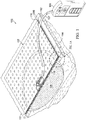
- FIG. 1 is a sectional view with a portion shown in elevation of an example embodiment of a therapy system 100 for negative-pressure therapy in accordance with this specification.
- the therapy system 100 may include a negative-pressure supply, such as a negative-pressure source 104, and may include or be configured to be coupled to a distribution component, such as a dressing 102.
- a distribution component may refer to any complementary or ancillary component configured to be fluidly coupled to a negative-pressure supply in a fluid path between a negative-pressure supply and a tissue site.
- a distribution component is preferably detachable, and may be disposable, reusable, or recyclable.
- the dressing 102 may be fluidly coupled to the negative-pressure source 104, as illustrated in Figure 1 .
- a dressing may include a tissue cover, a tissue interface, or both in some embodiments.
- the dressing 102 for example, may include a cover 106 and a tissue interface 108.
- a regulator or a controller may also be coupled to the negative-pressure source 104.
- a dressing interface may facilitate coupling the negative-pressure source 104 to the dressing 102.
- a dressing interface may be a T.R.A.C.® Pad or Sensa T.R.A.C.® Pad available from Kinetic Concepts, Inc. of San Antonio, Texas.
- the therapy system 100 may optionally include a fluid container coupled to or integral with the dressing 102 and to the negative-pressure source 104.
- a fluid container may include a container, canister, pouch, or other storage component, which can be used to manage exudates and other fluids withdrawn from a tissue site.
- a rigid container may be preferred or required for collecting, storing, and disposing of fluids.
- fluids may be properly disposed of without rigid container storage, and a re-usable container could reduce waste and costs associated with negative-pressure therapy.
- the therapy system 100 may include sensors to measure operating parameters and provide feedback signals to a controller of the negative-pressure source 104.
- the feedback signals can be indicative of the operating parameters, such as pressure at the tissue site, humidity at the tissue site, or temperature at the tissue site, for example.
- the therapy system 100 may include a pressure sensor, a humidity sensor, a temperature sensor, or the like.
- the sensors may be electrical sensors that can communicate with the therapy system 100 through electric signals.
- the sensors may be pneumatically or hydraulically operated.
- a pressure sensor may also be coupled or configured to be coupled to a distribution component and to the negative-pressure source 104.
- Components may be fluidly coupled to each other to provide a path for transferring fluids (i.e., liquid and/or gas) between the components.
- components may be fluidly coupled through a fluid conductor, such as a tube 107.
- a tube is an elongated, cylindrical structure with some flexibility, but the geometry and rigidity may vary.
- components may also be coupled by virtue of physical proximity, being integral to a single structure, or being formed from the same piece of material.
- some fluid conductors may be molded into or otherwise integrally combined with other components. Coupling may also include mechanical, thermal, electrical, or chemical coupling (such as a chemical bond) in some contexts.
- a tube may mechanically and fluidly couple the dressing 102 to a container.
- components of the therapy system 100 may be coupled to each other directly or indirectly.
- the negative-pressure source 104 may be directly coupled to the dressing 102 or indirectly coupled to the dressing 102 through a container.
- the fluid mechanics of using a negative-pressure source to reduce pressure in another component or location, such as within a sealed therapeutic environment, can be mathematically complex.
- the basic principles of fluid mechanics applicable to negative-pressure therapy are generally well-known to those skilled in the art, and the process of reducing pressure may be described illustratively herein as "delivering,” “distributing,” or “generating” negative pressure, for example.
- downstream typically implies a position in a fluid path relatively closer to a source of negative pressure or further away from a source of positive pressure.
- upstream implies a position relatively further away from a source of negative pressure or closer to a source of positive pressure.
- Negative pressure generally refers to a pressure less than a local ambient pressure, such as the ambient pressure in a local environment external to a sealed therapeutic environment provided by the dressing 102.
- the local ambient pressure may also be the atmospheric pressure at which a tissue site is located.
- the pressure may be less than a hydrostatic pressure associated with tissue at the tissue site.
- values of pressure stated herein are gauge pressures.
- references to increases in negative pressure typically refer to a decrease in absolute pressure, while decreases in negative pressure typically refer to an increase in absolute pressure.
- the pressure is generally a low vacuum, also commonly referred to as a rough vacuum, between -5 mmHg (-667 Pa) and -500 mmHg (-66.7 kPa).
- a rough vacuum between -5 mmHg (-667 Pa) and -500 mmHg (-66.7 kPa).
- Common therapeutic ranges are between -75 mmHg (-9.9 kPa) and -300 mmHg (-39.9 kPa).
- a negative-pressure supply such as the negative-pressure source 104, may be a reservoir of air at a negative pressure, or may be a manual or electrically-powered device that can reduce the pressure in a sealed volume, such as a vacuum pump, a suction pump, a wall suction port available at many healthcare facilities, or a micro-pump, for example.
- a negative-pressure supply may be housed within or used in conjunction with other components, such as sensors, processing units, alarm indicators, memory, databases, software, display devices, or user interfaces that further facilitate therapy.
- the negative-pressure source 104 may be combined with a controller and other components into a therapy unit.
- a negative-pressure supply may also have one or more supply ports configured to facilitate coupling and de-coupling the negative-pressure supply to one or more distribution components.
- the tissue interface 108 can be generally adapted to contact a tissue site.
- the tissue interface 108 may be partially or fully in contact with the tissue site. If the tissue site is a wound, for example, the tissue interface 108 may partially or completely fill the wound, or may be placed over the wound.
- the tissue interface 108 may take many forms, and may have many sizes, shapes, or thicknesses depending on a variety of factors, such as the type of treatment being implemented or the nature and size of a tissue site. For example, the size and shape of the tissue interface 108 may be adapted to the contours of deep and irregular shaped tissue sites. Moreover, any or all of the surfaces of the tissue interface 108 may have projections or an uneven, course, or jagged profile that can induce strains and stresses on a tissue site, which can promote granulation at the tissue site.
- the tissue interface 108 may be a manifold.
- a "manifold" in this context generally includes any substance or structure providing a plurality of pathways adapted to collect or distribute fluid across a tissue site under pressure.
- a manifold may be adapted to receive negative pressure from a negative-pressure supply and distribute negative pressure through multiple apertures across a tissue site, which may have the effect of collecting fluid from across a tissue site and drawing the fluid toward a negative-pressure supply.
- the fluid path may be reversed or a secondary fluid path may be provided to facilitate delivering fluid across a tissue site.
- a manifold may be a porous foam material having interconnected cells or pores.
- cellular foam, open-cell foam, reticulated foam, porous tissue collections, and other porous material such as gauze or felted mat generally include pores, edges, and/or walls adapted to form interconnected fluid channels.
- Liquids, gels, and other foams may also include or be cured to include apertures and fluid pathways.
- a manifold may additionally or alternatively comprise projections that form interconnected fluid pathways.
- a manifold may be molded to provide surface projections that define interconnected fluid pathways.
- the average pore size of a foam may vary according to needs of a prescribed therapy.
- the tissue interface 108 may be a foam having pore sizes in a range of about 400 to about 600 microns.
- the tensile strength of the tissue interface 108 may also vary according to the needs of a prescribed therapy.
- the tensile strength of a foam may be increased for instillation of topical treatment solutions.
- the tissue interface 108 may be an open-cell, reticulated polyurethane foam such as GranuFoam® dressing or VeraFlo® foam, both available from Kinetic Concepts, Inc. of San Antonio, Texas.
- the tissue interface 108 may be either hydrophobic or hydrophilic.
- the tissue interface 108 may also wick fluid away from a tissue site, while continuing to distribute negative pressure to the tissue site.
- the wicking properties of the tissue interface 108 may draw fluid away from a tissue site by capillary flow or other wicking mechanisms.
- An example of a hydrophilic foam is a polyvinyl alcohol, open-cell foam such as V.A.C. WhiteFoam® dressing available from Kinetic Concepts, Inc. of San Antonio, Texas.
- Other hydrophilic foams may include those made from polyether.
- Other foams that may exhibit hydrophilic characteristics include hydrophobic foams that have been treated or coated to provide hydrophilicity.
- the tissue interface 108 may further promote granulation at a tissue site when pressure within a sealed therapeutic environment is reduced.
- any or all of the surfaces of the tissue interface 108 may have an uneven, coarse, or jagged profile that can induce microstrains and stresses at a tissue site if negative pressure is applied through the tissue interface 108.
- the tissue interface 108 may be constructed from bioresorbable materials. Suitable bioresorbable materials may include, without limitation, a polymeric blend of polylactic acid (PLA) and polyglycolic acid (PGA). The polymeric blend may also include without limitation polycarbonates, polyfumarates, and capralactones.
- the tissue interface 108 may further serve as a scaffold for new cell-growth, or a scaffold material may be used in conjunction with the tissue interface 108 to promote cell-growth.
- a scaffold is generally a substance or structure used to enhance or promote the growth of cells or formation of tissue, such as a three-dimensional porous structure that provides a template for cell growth.
- Illustrative examples of scaffold materials include calcium phosphate, collagen, PLA/PGA, coral hydroxy apatites, carbonates, or processed allograft materials.
- the cover 106 may be a sealing member configured to provide a bacterial barrier and protection from physical trauma.
- the cover 106 may also be constructed from a material that can reduce evaporative losses and provide a fluid seal between two components or two environments, such as between a therapeutic environment and a local external environment.
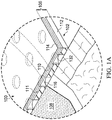
- Figure 1A is a detail view of a portion of the therapy system 100 of Figure 1 , illustrating additional details that may be associated with the cover 106.
- the cover 106 may be, for example, a film layer 114 or membrane that can provide a seal adequate to maintain a negative pressure at a tissue site for a given negative-pressure source.
- the cover 106 may have a high moisture-vapor transmission rate (MVTR) in some applications.
- MVTR moisture-vapor transmission rate
- the MVTR may be at least about 300 g/m 2 per twenty-four hours.
- the cover 106 may be a polymer cover, such as a polyurethane film, that is permeable to water vapor but impermeable to liquid. Such covers typically have a thickness in the range of about 25 to about 50 microns. For permeable materials, the permeability generally should be low enough that a desired negative pressure may be maintained.
- the cover 106 may include an attachment device to attach the cover 106 to an attachment surface, such as undamaged epidermis, a gasket, or another cover.
- the attachment device may take many forms.
- an attachment device may be a medically-acceptable, pressure-sensitive adhesive that extends about a periphery, a portion, or an entire sealing member.
- some or all of the cover 106 may be coated with an acrylic adhesive having a coating weight between about 25 and about 65 grams per square meter (g.s.m.). Thicker adhesives, or combinations of adhesives, may be applied in some embodiments to improve the seal and reduce leaks.
- Other example embodiments of an attachment device may include a double-sided tape, paste, hydrocolloid, hydrogel, silicone gel, or organogel.
- the attachment device may comprise a first adhesive layer 110 and a second adhesive layer 112.
- the first adhesive layer 110 may be a continuous adhesive layer and may be secured to the film layer 114.
- the second adhesive layer 112 may be secured to the first adhesive layer 110 and have a plurality of apertures 116 extending through the second adhesive layer 112.
- a support layer 111 may be disposed between the second adhesive layer 112 and the first adhesive layer 110.
- the support layer 111 may have a plurality of apertures 132.
- the tissue interface 108 may be placed within, over, on, or otherwise proximate to a tissue site.
- the cover 106 may be placed over the tissue interface 108 and sealed to an attachment surface near the tissue site.
- the cover 106 may be sealed to undamaged epidermis peripheral to a tissue site.
- the dressing 102 can provide a sealed therapeutic environment proximate to a tissue site that is substantially isolated from the external environment.
- the negative-pressure source 104 can reduce the pressure in the sealed therapeutic environment. Negative pressure applied across the tissue site through the tissue interface 108 in the sealed therapeutic environment can induce macrostrain and microstrain in the tissue site, as well as remove exudates and other fluids from the tissue site, which can be collected in a container.
- a battery or other portable power supply may supply power to the negative-pressure source 104.
- Use of battery power can significantly decrease the total power available to a negative-pressure supply.
- power drains that would be considered negligible in a device powered through an electrical outlet connection may significantly reduce the ability of the negative-pressure supply to provide therapy.
- a power drain refers to operation of the negative-pressure supply that requires use of electrical power, for example, operation of a pump to generate negative pressure.
- Power drains may be caused by small dressing leaks, for example.
- a small dressing leak can drain power from a battery of a negative-pressure supply by repeatedly triggering operation of the negative-pressure supply to maintain the necessary negative pressure at the tissue site.
- Leak detection techniques may help to identify some leaks that may then be sealed by the user; however, small leaks will challenge the most sensitive leak detection systems and may often go undetected.
- Covers can be a balance between the strength of the attachment device required to enable the cover to seal against leaks and the pain which may result if the cover is removed.
- adhesives used to form the attachment device can be loosely classified as “bonding” adhesives or “sealing" adhesives.
- a bonding adhesive is generally stronger than a sealing adhesive.
- a bonding adhesive may also provide a suitable seal, but the strength of a bonding adhesive can cause significantly more discomfort upon removal. In addition, removing a cover with a bonding adhesive may cause significant damage to patients having delicate or damaged skin.
- a sealing adhesive can generally be characterized by lower strength and lower viscosity than a bonding adhesive.
- a cover that has a sealing adhesive can fill gaps between the cover and the epidermis to limit leaks and can be easy to remove with low discomfort to the patient.
- Various sealing, gap-filling adhesives such as silicone, hydrocolloids, and hydrogels, have been tried but each has drawbacks.
- hydrogel adhesives are usually low tack and prone to swelling, creep, and mobility when used with fluid systems.
- silicone adhesives can fill gaps and seal, but are not breathable and may lose the necessary mechanical bonding strength as the silicone adhesives interact with moisture during use. To counter these problems, silicone adhesives often require additional materials to secure the silicone adhesive to the patient.
- a low-leak cover may be formed from two adhesive layers: a thick sealing adhesive, perhaps in the shape of a gasket or ring, and a thinner bonding adhesive layer used to keep the sealing adhesive in place.
- the thinner bonding adhesive may be applied as cover strips, or combined with the thicker sealing adhesive as an outer border.
- a hybrid cover having a thick sealing layer that is perforated and laminated over an adhesive-coated film can overcome some of these challenges.
- a hybrid cover may include a film layer having a bonding adhesive applied directly to the film layer, and a sealing adhesive applied directly to the bonding adhesive.
- the bonding adhesive and the sealing adhesive can be laminated to the film layer by applying the bonding adhesive and the sealing adhesive to the film layer in a liquid form and the curing the bonding adhesive and the sealing adhesive in place on the film layer.
- Curing may involve toughening or hardening of polymer material by cross-linking of polymer chains within the polymer material. Curing can include the addition of heat, chemical additives and ultraviolet radiation to cause cross-linking within the polymer material.
- the sealing adhesive can be perforated to expose the bonding adhesive. If the cover is applied to a patient, the bonding adhesive can be pushed through the perforations of the sealing adhesive to secure the sealing adhesive to the patient.
- This laminated configuration may provide the benefits of the sealing adhesive and the bonding adhesive over the entire cover area.
- the laminated configuration may be conformable and of sufficient strength to seal small leaks, and can be mechanically affixed to an epidermis without secondary processes.
- the laminated configuration can also be removable with minimal trauma to the patient.
- a thick sealing adhesive may be applied to a scrim layer.
- a scrim layer may be a sheet of strong, coarse fabric or webbing.
- the sealing adhesive may be cast onto the scrim layer and cured around the scrim layer. Casting involves pouring a liquid material, for example an adhesive, into a mold having a hollowed cavity of the desired shape. The liquid material is allowed to solidify or cure into a solid or semi-solid body.
- the scrim layer may provide support for the sealing adhesive and can aid in the manipulation of the sealing adhesive during the manufacturing process. After casting the sealing adhesive onto the scrim layer, the sealing adhesive and scrim layer may be coupled to an adhesive coated film layer to form a cover.
- fabric in the scrim layer can inhibit the light transmittance of the cover by increasing the absorbance of the cover.
- the scrim layer may be a barrier in the cover that can absorb light.
- the scrim layer may also reflect light transmitting through the cover, or scatter light reflecting through the cover, causing the light to be attenuated by the cover. As the light is absorbed, reflected or scattered, the light cannot reflect off of a wound covered by the cover. As a consequence, the scrim layer may cause the cover to appear opaque and prevent a clinician from seeing through the cover to view the dressing or tissue site.
- the scrim layer may also add additional thickness to the sealing layer. If the scrim layer is exposed, the exposed portions may prevent the sealing layer from forming an effective seal between the cover and the epidermis. As a result, additional sealing adhesive may be needed to ensure that the scrim layer is not exposed.
- the coarse fabric or webbing of a scrim layer may also have large openings between threads of the fabric or webbing. If the sealing adhesive is cast onto the scrim layer, the sealing adhesive may need to fill the openings in the fabric. As a result, if a scrim layer is used, even more sealing adhesive may be needed to completely cover the scrim layer and provide a surface for adhesion of the sealing adhesive to a patient.
- the scrim layer, along with any additional sealing adhesive needed, may add stiffness to the cover, reducing the conformability of the cover and inhibiting the ability of the sealing adhesive to migrate and seal to tissue.
- Light transmittance can also be improved to provide accurate cover positioning and visualization of the tissue interface and periwound during treatment.
- flexibility and conformability can be increased, and adhesives used more efficiently when manufacturing the cover. Increased efficiency of adhesive use may enable a thinner coating of adhesive, which can decrease the cost.
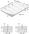
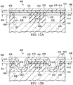
- FIG 2 is a perspective exploded view of an example embodiment of the cover 106.
- the cover 106 may include the film layer 114, the first adhesive layer 110 adjacent to the film layer 114, the support layer 111 adjacent to the first adhesive layer 110, and the second adhesive layer 112 adjacent to the support layer 111.
- the film layer 114 may be formed from a range of medically approved films ranging in thickness from about 15 microns ( ⁇ m) to about 50 microns ( ⁇ m).
- the film layer 114 may comprise a suitable material or materials, such as the following: hydrophilic polyurethane (PU), cellulosics, hydrophilic polyamides, polyvinyl alcohol, polyvinyl pyrrolidone, hydrophilic acrylics, hydrophilic silicone elastomers, and copolymers of these.
- PU hydrophilic polyurethane
- the film layer 114 may be formed from a breathable cast matt polyurethane film sold by Expopack Advanced Coatings of Wrexham, United Kingdom, under the name INSPIRETM 2301 or INSPIRETM 2327.
- the film layer 114 may have a high moisture-vapor-transfer-rate (MVTR).
- a high MVTR may allow vapor to egress the sealed therapeutic environment through the film layer 114 and inhibit liquids from exiting the sealed therapeutic environment through the film layer 114.
- the MVTR of the film layer 114 may be greater than or equal to about 300 grams per meter squared per twenty-four hours (g/m 2 /24 hours). In other embodiments, the MVTR of the film layer 114 may be greater than or equal to about 1000 g/m 2 /24 hours.
- the illustrative INSPIRETM 2301 film may have an MVTR (tested using the inverted cup technique) of about 14400 g/m2/24 hours and may be about 30 microns thick. In other embodiments, a film having a low MVTR or that allows no vapor transfer might be used.
- the film layer 114 can also function as a barrier to microorganisms.
- the film layer 114 may have a first side 118 and a second side 120.
- the first adhesive layer 110 may also have a first side 122 and a second side 124.
- the first side 122 of the first adhesive layer 110 may face the second side 120 of the film layer 114.
- the first adhesive layer 110 may be a medically-acceptable, pressure-sensitive adhesive, glue, bonding agent, or cement.
- the first adhesive layer 110 may be formed from or include a bonding adhesive.
- the bonding adhesive may be a high bond strength acrylic adhesive, patterrubber adhesive, high-tack silicone adhesive, or polyurethane, for example.
- the bond strength of the bonding adhesive may have a peel adhesion or resistance to being peeled from a stainless steel material between about 6N/25mm to about 10N/25mm on stainless steel substrate at 23° C at 50% relative humidity based on the American Society for Testing and Materials ("ASTM") standard ASTM D3330.
- the bonding adhesive of the first adhesive layer 110 comprises an acrylic adhesive with a coating weight of about 10 grams/m 2 (gsm) to about 70 grams/m 2 (gsm).
- the first adhesive layer 110 may have a thickness 156, and in some embodiments, the thickness 156 of the first adhesive layer 110 may be about 30 microns to about 60 microns.
- the support layer 111 may have a first side 123 and a second side 125. In some embodiments, the first side 123 of the support layer 111 may face the second side 124 of the first adhesive layer 110.
- the support layer 111 may be an elastomeric film and may have a high moisture-vapor-transfer-rate (MVTR) similar to the film layer 114.
- the support layer 111 may be formed from a range of medically-approved films ranging in thickness from about 15 microns ( ⁇ m) to about 50 microns ( ⁇ m).
- the support layer 111 may comprise a suitable material or materials, such as the following: hydrophilic polyurethane (PU), cellulosics, hydrophilic polyamides, polyvinyl alcohol, polyvinyl pyrrolidone, hydrophilic acrylics, hydrophilic silicone elastomers, and copolymers of these.
- PU hydrophilic polyurethane
- the support layer 111 may be formed from a breathable cast matt polyurethane film sold by Expopack Advanced Coatings of Wrexham, United Kingdom under the name INSPIRE 2301 or INSPIRE 2327.
- the MVTR of the support layer 111 may be greater than or equal to about 300g/m 2 /24 hours. In other embodiments, the MVTR of the support layer 111 may be greater than or equal to about 1000g/m 2 /24 hours.
- the illustrative INSPIRETM 2301 film may have an MVTR (inverted cup technique) of about 14400 g/m 2 /24 hours and may be about 30 microns thick. In other embodiments, a support layer having a low MVTR or that allows no vapor transfer might be used.
- the support layer 111 can also function as a barrier to liquids and microorganisms.
- the support layer 111 may have a plurality of apertures 132.
- Each aperture 132 of the plurality of apertures 132 may extend through the support layer 111 from the first side 123 to the second side 125.
- the plurality of apertures 132 may be numerous shapes, including without limitation, circles, squares, stars, ovals, polygons, slits complex curves, rectilinear shapes, or triangles.
- Each aperture 132 of the plurality of apertures 132 may have an effective diameter.
- An effective diameter of a non-circular area is the diameter of a circular area having the same area as the non-circular area. The average effective diameter is typically in the range of about 4 mm to about 50 mm.
- the plurality of apertures 132 may have a uniform pattern or may be randomly distributed on the support layer 111. In some embodiments, the apertures 132 may be distributed so that centers of adjacent apertures 132 may be separated by between about 5 mm and about 100 mm. In other embodiments, the apertures 132 may be distributed so that the centers of adjacent apertures 132 may be separated by about 10 mm.
- the plurality of apertures 132 in the support layer 111 may leave void spaces in the support layer 111.
- the percentage of void space of the plurality of apertures 132 may be equal to the percentage of the volume or surface area of the void spaces created by the plurality of apertures 132 to the total volume or surface area of the support layer 111. In some embodiments, the percentage of void space may be between about 40% and about 75%. In other embodiments, the percentage of void space may be about 55%.
- the organization of the plurality of apertures 132 can also impact the percentage of void space.
- the plurality of apertures 132 may be formed by punching, cutting, melting, or drilling the support layer 111.
- the second adhesive layer 112 may have a first side 126 and a second side 128.
- the first side 126 of the second adhesive layer 112 may face the second side 125 of the support layer 111 and have a thickness 154.
- the second adhesive layer 112 may be formed from or include a sealing adhesive.
- the sealing adhesive may be an adhesive having a low to medium tackiness, for example, a silicone polymer, polyurethane, or an additional acrylic adhesive. Generally, tackiness may be understood as a bond strength of an adhesive after a very short contact time between the adhesive and a substrate, such as less than 60 seconds.
- the bond strength of the sealing adhesive may have a peel adhesion or resistance to being peeled from a stainless steel material between about 0.5N/25mm to about 1.5N/25mm on stainless steel substrate at 23° C at 50% relative humidity based on ASTM D3330.
- the sealing adhesive may achieve its bond strength above after a contact time with the substrate of less than 60 seconds.
- the sealing adhesive may have a coating weight between about 150 gsm and about 250 gsm, be about 100 microns to about 400 microns thick, and have a tackiness that may be about 30% to about 50% of the tackiness of the bonding adhesive that may be used in the first adhesive layer 110.
- a catalyst may be added to the sealing adhesive to provide additional therapeutic properties; for example, a platinum catalyst or a sulfur catalyst may be added to the sealing adhesive to aid in treatment.
- the second adhesive layer 112 may have a plurality of apertures 116 that extend through the second adhesive layer 112 from the first side 126 to the second side 128.
- the plurality of apertures 116 may be, for example, circles, squares, stars, ovals, polygons, slits, complex curves, rectilinear shapes, triangles, or other shapes.
- Each aperture 116 of the plurality of apertures 116 may have an effective diameter typically in the range of about 4 mm to about 50 mm.
- the plurality of apertures 116 may have a uniform pattern or may be randomly distributed on the second adhesive layer 112. In some embodiments, the apertures 116 may be distributed so that centers of adjacent apertures 116 may be separated by between about 5 mm and about 100 mm. In other embodiments, the apertures 116 may be distributed so that the centers of adjacent apertures 116 may be separated by about 10 mm.
- the plurality of apertures 116 in the second adhesive layer 112 may leave void spaces in the second adhesive layer 112.
- the percentage of void space of the plurality of apertures 116 may be equal to the percentage of the volume or surface area of the void spaces created by the plurality of apertures 116 to the total volume or surface area of the second adhesive layer 112. In some embodiments, the percentage of void space may be between about 40% and about 75%. In other embodiments, the percentage of void space may be about 55%.
- the organization of the plurality of apertures 116 can also impact the percentage of void space.
- the plurality of apertures 116 may be formed by punching, cutting, melting, or drilling, for example.
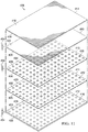
- Figure 3 is a perspective view of the cover 106 partially assembled, illustrating additional details that may be associated with some embodiments.
- the film layer 114 may be coupled to the first adhesive layer 110.
- the second side 120 of the film layer 114 may be in contact with and coupled to the first side 122 of the first adhesive layer 110.
- the film layer 114 and the first adhesive layer 110 may be coextensive.
- the second side 120 of the film layer 114 and the first side 122 of the first adhesive layer 110 may be in contact across the entirety of their respective surface areas.
- the film layer 114 may be coupled to the first adhesive layer 110 by bonding, adhering, welding, or cross-linking, for example.
- the support layer 111 may be coupled to the second adhesive layer 112.
- the second side 125 of the support layer 111 may be in contact with and coupled to the first side 126 of the second adhesive layer 112.
- the support layer 111 and the second adhesive layer 112 may be coextensive.
- the first side 126 of the second adhesive layer 112 and the second side 125 of the support layer 111 may be in contact across the entirety of their respective surface areas.
- the support layer 111 may be coupled to the second adhesive layer 112 by bonding, adhering, welding, or cross-linking, for example.
- the plurality of apertures 132 may be distributed in the support layer 111 so that the plurality of apertures 132 are aligned with the plurality of apertures 116 of the second adhesive layer 112 if the support layer 111 and the second adhesive layer 112 are coupled.
- each aperture 132 of the support layer 111 may be aligned with a corresponding aperture 116 of the second adhesive layer 112.
- Figure 4A is a schematic view of the assembled cover 106 in a first position on the epidermis, illustrating additional details that may be associated with some embodiments.
- the second side 120 of the film layer 114 may be coupled to first side 122 of the first adhesive layer 110.
- the second side 124 of the first adhesive layer 110 may be coupled to the first side 123 of the support layer 111.
- the second side 125 of the support layer 111 may be coupled to the first side 126 of the second adhesive layer 112.
- the cover 106 may be disposed over the epidermis to form the sealed therapeutic environment.
- the tackiness of the sealing adhesive of the second adhesive layer 112 may form sealing couplings 150 between the second side 128 of the second adhesive layer 112 and the epidermis to hold the cover 106 in an initial position as illustrated in Figure 4A .
- the tackiness of the sealing adhesive of the second adhesive layer 112 may be such that the cover 106 may be removed and reapplied or repositioned.
- the thickness 154 of the second adhesive layer 112 may prevent the first adhesive layer 110 from contacting the epidermis, forming a gap 139 between the first adhesive layer 110 and the epidermis.
- Figure 4B is a schematic view of the cover 106 in a second position, illustrating additional details that may be associated with some embodiments.
- a force may be applied to the first side 118 of the film layer 114.
- the force may cause at least some portion of the bonding adhesive of the first adhesive layer 110 to move through the apertures 116.
- the second side 124 of the first adhesive layer 110 may contact the epidermis and form bonding couplings 152, as illustrated in the second position of Figure 4B .
- the bonding couplings 152 may be located where the second side 124 of the first adhesive layer 110 adheres to the epidermis.
- the bonding couplings 152 may have a peel force against the epidermis between about 0.5N/25mm and about 2N/25mm.
- the average effective diameter of the plurality of apertures 116 for the second adhesive layer 112 may be varied as one control of the tackiness or adhesion strength of the cover 106.
- the strength of the bond of the bonding coupling 152 is proportional to the effective diameter of the plurality of apertures 116 of the second adhesive layer 112, the thickness 154 of the second adhesive layer 112, and the tackiness of the first adhesive layer 110. The more of the first adhesive layer 110 that extends through the apertures 116, the more bonding adhesive of the first adhesive layer 110 contacts the epidermis and the stronger the bond of the bonding coupling 152.
- the thickness 154 of the second adhesive layer 112 may permit more of the first adhesive layer 110 to extend through the apertures 116 and increase the bond of the bonding coupling 152.
- the average effective diameter of the plurality of apertures 116 may be a first effective diameter so that the bonding couplings 152 have a first bond strength. If the thickness 154 of the second adhesive layer 112 is increased to be larger than the first thickness, the average effective diameter may increase to be larger than the first effective diameter to achieve the first bond strength of the bonding coupling 152.
- the thickness 154 may be about 200 microns
- the first adhesive layer 110 may be about 30 microns with a bonding adhesive having a tackiness of about 2000g/25cm wide strip
- the average effective diameter of each aperture 116 of the plurality of apertures 116 may be about 6 mm.
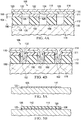
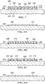
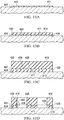
- the cover 106 can be manufactured in many ways including by following the operations provided below to produce the cover 106 without a scrim layer. The operations can be performed using manufacturing processes and equipment to manipulate the materials as described below.
- Figure 5A is a schematic view illustrating additional details that may be associated with some embodiments of the manufacturing process of the cover 106.
- the support layer 111 may be provided and suitably disposed so that the first side 123 is supported by a suitable surface, and the second side 125 is exposed.
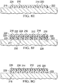
- Figure 5B is a schematic view illustrating additional details that may be associated with some embodiments of the manufacturing process of the cover 106.
- a sealing adhesive may be cast onto the second side 125 of the support layer 111.
- the sealing adhesive may be cured or otherwise cross-linked to form the second adhesive layer 112 and couple the second adhesive layer 112 to the second side 125 of the support layer 111.
- the sealing adhesive of the second adhesive layer 112 may be a two-part silicone system, such as those provided by Wacker, Dow, or NuSil. To cure, the two-part silicone system may be heated once applied to the second side 125 of the support layer 111. Heating may encourage cross-linking or curing to cause the two-part silicone system to form a gel.
- the sealing adhesive may be a one-part silicone system, and the sealing adhesive may be cured or cross-linked by exposing the one-part silicone system to ultraviolet light or ionizing radiation.
- the support layer 111 may be laminated to the second adhesive layer 112.
- the sealing adhesive of the second adhesive layer 112 may be cast and cured as described above. After the sealing adhesive has cured to form the second adhesive layer 112, the support layer 111 may be laminated to the second adhesive layer 112.
- Figure 5C is a schematic view illustrating additional details that may be associated with some embodiments of the manufacturing process of the cover 106.
- the plurality of apertures 116 and the plurality of apertures 132 may be formed following casting of the second adhesive layer 112 onto the support layer 111.
- the apertures 116 and the apertures 132 may be formed using shaped pins that puncture the support layer 111 and the second adhesive layer 112 as the support layer 111 and the second adhesive layer 112 move along a manufacturing path.
- the apertures 116 and the apertures 132 may be formed by rolling a drum having shaped pins along the support layer 111 and the second adhesive layer 112.
- the shaped pins may be configured to make the desired shape and size of the apertures 116 and the apertures 132.
- the apertures 116 and the apertures 132 may be cut or torn.
- a punch may be used to puncture the support layer 111 and the second adhesive layer 112.
- the apertures 116 and the apertures 132 may also be formed by melting portions of the support layer 111 and the second adhesive layer 112.
- a heated element such as a poker may be applied to the support layer 111 and the second adhesive layer 112, melting portions of the support layer 111 and the second adhesive layer 112.
- the apertures 116 and the apertures 132 may be formed in the second adhesive layer 112 and the support layer 111, respectively, prior to the coupling of the support layer 111 and the second adhesive layer 112 to each other.
- a mold may be used to form the second adhesive layer 112.
- the sealing adhesive may be cast into a mold having projections that extend into the sealing adhesive. After the sealing adhesive is cured, the mold and projections may be removed, leaving the apertures 116 formed in the second adhesive layer 112.
- the support layer 111 may then be laminated to the second adhesive layer 112. If the apertures 116 are formed with a mold, the apertures 132 may be separately formed in the support layer 111.
- Figure 5D is a schematic view illustrating additional details that may be associated with some embodiments of the manufacturing process of the cover 106.
- the film layer 114 may be provided and positioned so that the first side 118 is supported by a suitable surface and the second side 120 is exposed.
- Figure 5E is a schematic view illustrating additional details that may be associated with some embodiments of the manufacturing process of the cover 106.
- the first adhesive layer 110 may be cast onto the second side 120 of the film layer 114 of Figure 5D .
- the first adhesive layer 110 may be cast and cured, and the film layer 114 may then be laminated to the first adhesive layer 110.
- Figure 5F is a schematic view illustrating additional details that may be associated with some embodiments of the manufacturing process of the cover 106.
- the support layer 111 and the second adhesive layer 112 may be positioned so that the first side 123 of the support layer 111 is proximate to the second side 124 of the first adhesive layer 110 of Figure 5E .
- the first side 123 of the support layer 111 may be coupled to the second side 124 of the first adhesive layer 110 to form the cover 106 as shown in the example of Figure 5F .
- the second side 124 of the first adhesive layer 110 may be brought proximate to the first side 123 of the support layer 111.
- the second side 124 of the first adhesive layer 110 may then be coupled to the first side 123 of the support layer 111, forming the cover 106.
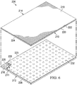
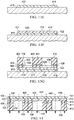
- FIG 6 is perspective view of a cover 206 partially assembled, which may be associated with some embodiments of the therapy system 100 of Figure 1 , for example.
- the cover 206 may be similar to the cover 106 as described above with respect to Figures 1-5F . Similar elements may have similar reference numbers that are indexed to 200.
- a film layer 214 may be coupled to a first adhesive layer 210.
- a second side 220 of the film layer 214 may be in contact with and coupled to a first side 222 of the first adhesive layer 210.
- the film layer 214 and the first adhesive layer 210 may be coextensive.
- the film layer 214 may be coupled to the first adhesive layer 210 by bonding, adhering, welding, or cross-linking, for example.
- a support layer 211 may be coupled to a second adhesive layer 212.
- a second side 225 of the support layer 211 may be in contact with and coupled to a first side 226 of the second adhesive layer 212.
- the support layer 211 and the second adhesive layer 212 may be coextensive.
- the support layer 211 may be coupled to the second adhesive layer 212 by bonding, adhering, welding, or cross-linking, for example.
- a plurality of apertures 232 may be distributed in the support layer 211 so that the plurality of apertures 232 are aligned with a plurality of apertures 216 of the second adhesive layer 212.
- the plurality of apertures 232 and the plurality of apertures 216 may be said to be coextensive so that each aperture 232 is aligned with a corresponding aperture 216.
- the support layer 211 may be removed prior to final assembly of the cover 206.
- the support layer 211 may be removed by peeling the support layer 211 from the second adhesive layer 212.
- Figure 7 is a sectional view of the cover 206 illustrating additional details that may be associated with some embodiments. If the support layer 211 is removed, the first adhesive layer 210 may be coupled directly to the second adhesive layer 212 to produce the cover 206. The cover 206 may be used as described above with respect to the cover 106 in Figure 4A and Figure 4B .
- the cover 206 can be manufactured without the use of a scrim layer. The operations can be performed using manufacturing processes and equipment to manipulate the materials as described below.
- Figure 8A is a schematic view illustrating additional details that may be associated with some embodiments of the manufacturing process of the cover 206.
- the support layer 211 may be provided and suitably disposed so that the first side 223 is supported by a suitable surface, and the second side 225 is exposed.
- Figure 8B is a schematic view illustrating additional details that may be associated with some embodiments of the manufacturing process of the cover 206.
- a sealing adhesive may be cast onto the second side 225 of the support layer 211.
- the sealing adhesive may be cured or otherwise cross-linked to form the second adhesive layer 212 and couple the second adhesive layer 212 to the second side 225 of the support layer 211.
- the sealing adhesive of the second adhesive layer 212 may be a two-part silicone system, such as those provided by Wacker, Dow, or NuSil. To cure, the two-part silicone system may be heated once applied to the second side 225 of the support layer 211. Heating may cause crosslinking or curing to cause the two-part silicone system to form a gel.
- the sealing adhesive may be a one-part silicone system, and the sealing adhesive may be cured or crosslinked by exposing the one-part silicone system to ultraviolet light or ionizing radiation.
- the support layer 211 may be laminated to the second adhesive layer 212.
- the sealing adhesive of the second adhesive layer 212 may be cast and cured as described above. After the sealing adhesive has cured to form the second adhesive layer 212, the support layer 211 may be laminated to the second adhesive layer 212.
- Figure 8C is a schematic view illustrating additional details that may be associated with some embodiments of the manufacturing process of the cover 206.
- the plurality of apertures 216 and the plurality of apertures 232 may be formed following casting of the second adhesive layer 212 onto the support layer 211.
- the apertures 216 and the apertures 232 may be formed using shaped pins that puncture the support layer 211 and the second adhesive layer 212 as the support layer 211 and the second adhesive layer 212 move along a manufacturing path.
- the apertures 216 and the apertures 232 may be formed by rolling a drum having shaped pins along the support layer 211 and the second adhesive layer 212.
- the shaped pins may be configured to make the desired shape and size of the apertures 216 and the apertures 232.
- the apertures 216 and the apertures 232 may be cut or torn.
- a punch may be used to puncture the support layer 211 and the second adhesive layer 212.
- the apertures 216 and the apertures 232 may also be formed by melting portions of the support layer 211 and the second adhesive layer 212.
- a heated element such as a poker may be applied to the support layer 211 and the second adhesive layer 212, melting portions of the support layer 211 and the second adhesive layer 212.
- the apertures 216 and the apertures 232 may be formed in the second adhesive layer 212 and the support layer 211, respectively, prior to the coupling of the support layer 211 and the second adhesive layer 212.
- a mold may be used to form the second adhesive layer 212.
- the sealing adhesive may be cast into a mold having projections that extend into the sealing adhesive. After the sealing adhesive is cured, the mold and projections may be removed, leaving the apertures 216 formed in the second adhesive layer 212.
- the support layer 211 may then be laminated to the second adhesive layer 212. In some embodiments, the support layer 211 may not include the plurality of apertures 232.
- Figure 8D is a schematic view illustrating additional details that may be associated with some embodiments of the manufacturing process of the cover 206.
- the film layer 214 may be provided and positioned so that the first side 218 is supported by a suitable surface and the second side 220 is exposed.
- Figure 8E is a schematic view illustrating additional details that may be associated with some embodiments of the manufacturing process of the cover 206.
- the first adhesive layer 210 may be cast onto the second side 220 of the film layer 214 of Figure 8D .
- the first adhesive layer 210 may be cast and cured and the film layer 214 may then be laminated to the first adhesive layer 210.
- Figure 8F is a schematic view illustrating additional details that may be associated with some embodiments of the manufacturing process of the cover 206.
- the second adhesive layer 212 and the support layer 211 may be positioned so that the first side 223 of the support layer 211 is in contact with a surface, leaving the second side 228 of the second adhesive layer 212 free.
- the second side 224 of the first adhesive layer 210 of Figure 8E may be brought proximate to the second side 228 of the second adhesive layer 212.
- the second side 224 of the first adhesive layer 210 may then be coupled to the second side 228 of the second adhesive layer 212, as illustrated in the example of Figure 8F , forming one embodiment of the cover 206.
- Figure 8G is a schematic view illustrating additional details that may be associated with some embodiments of the manufacturing process of the cover 206.
- the cover 206 may be repositioned so that the first side 223 of the support layer 211 is exposed.
- the support layer 211 may then be removed from the first side 226 of the second adhesive layer 212.
- Figure 9A is a perspective view of the cover 206, illustrating additional details that may be associated with some embodiments.
- the cover 206 includes the film layer 214, the first adhesive layer 210 coupled to the film layer 214, and the second adhesive layer 212 having the apertures 216 coupled to the first adhesive layer 210.
- the cover 206 may include one or more sizing lines 240.
- Each sizing line 240 may extend across the cover 206 from a first edge 244 to a second edge 246.
- the sizing lines 240 may be equidistantly spaced across the cover 206.
- each sizing line 240 may be between about 5 centimeters and about 30 centimeters from adjacent sizing lines 240. In other embodiments, each sizing line 240 may be about 28 centimeters from adjacent sizing lines 240.
- a sizing line 240 may be a weakened portion of the cover 206 that facilitates separation of a first portion of the cover 206 from a second portion of the cover 206.
- each sizing line 240 may be formed by perforating the cover 206.
- each sizing line 240 may have a plurality of perforations 242.
- each perforation 242 may be between about 25 mm and about 60 mm from adjacent perforations 242 in the same sizing line 240. While each sizing line 240 is shown in portions of the cover 206 between apertures 216, in other embodiments, the sizing lines 240 may pass through the apertures 216.
- FIG 9B is a schematic view of the cover 206, illustrating additional details that may be associated with some embodiments of the perforations 242.
- each perforation 242 may be formed in the cover 206 that extends through the film layer 214, the first adhesive layer 210, and the second adhesive layer 212. If the cover 206 is applied to a tissue site and a sizing line 240 extends across the sealed therapeutic environment, the sealing adhesive of the second adhesive layer 212 may expand and fill the perforation 242 to seal the cover 206.
- FIG 9C is a sectional view of the cover 206, illustrating additional details that may be associated with some embodiments of the perforations 242.
- each perforation 242 may be formed in the cover 206 that extends through the film layer 214 and the first adhesive layer 210, but not the second adhesive layer 212.
- the cover 206 may be torn along the sizing line 240 to separate portions of the cover 206.
- FIG 10 is a perspective exploded view of an example embodiment of a cover 306 that can be used with the therapy system 100.
- the cover 306 may include a first adhesive layer 310, a support layer 311, a second adhesive layer 312, and a film layer 314.
- the first adhesive layer 310, the support layer 311, the second adhesive layer 312, and the film layer 314 may be similar to and operate as described above with respect to the first adhesive layer 110, the support layer 111, the second adhesive layer 112, and the film layer 114.
- the film layer 314 may have a first side 318 and a second side 320.
- the first adhesive layer 310 may also have a first side 322 and a second side 324.
- the first side 322 of the first adhesive layer 310 may face the second side 320 of the film layer 314.
- the first adhesive layer 310 may have a thickness 356, and in some embodiments, the thickness 356 of the first adhesive layer 310 may be about 30 microns to about 60 microns. In some embodiments, the first adhesive layer 310 may be coupled to the film layer 314.
- the support layer 311 may have a first side 323 and a second side 325. In some embodiments, the support layer 311 may have a plurality of apertures 332. Each aperture 332 of the plurality of apertures 332 may extend through the support layer 311 from the first side 323 to the second side 325. In some embodiments, the support layer 311 may have a thickness of about 15 microns. The first side 323 of the support layer 311 may also have a substantially smooth surface.
- the cover 306 may also include a third adhesive layer 313.
- the third adhesive layer 313 may be disposed between the support layer 311 and the second adhesive layer 312.
- the third adhesive layer 313 may have a first side 334 and a second side 336.
- the first side 334 of the third adhesive layer 313 may face the second side 325 of the support layer 311.
- the third adhesive layer 313 may have a plurality of apertures 338 that extend through the third adhesive layer 313 from the first side 334 to the second side 336.
- the third adhesive layer 313 may be an acrylic adhesive having a coating weight between 25-65 grams per square meter (g.s.m.).
- the third adhesive layer 313 may have a thickness 358.
- the thickness 358 of the third adhesive layer 313 may be between about 30 microns and about 60 microns. In other embodiments, the thickness 358 of the third adhesive layer 313 may be between about 15 microns and about 25 microns. Thicker adhesives, or combinations of adhesives, may be applied in some embodiments to improve the seal and reduce leaks. Other example embodiments of the third adhesive layer 313 may include a double-sided tape, paste, hydrocolloid, hydrogel, silicone gel, or organogel.
- the second adhesive layer 312 may have a first side 326 and a second side 328.
- the first side 326 of the second adhesive layer 312 may face the second side 336 of the third adhesive layer 313 and have a thickness 354.
- the second adhesive layer 312 may have a plurality of apertures 316 that extend through the second adhesive layer 312 from the first side 326 to the second side 328.
- the plurality of apertures 332, 338, 316 may be numerous shapes, including without limitation, circles, squares, stars, ovals, polygons, slits complex curves, rectilinear shapes, or triangles. Each aperture 332, 338, 316 of the plurality of apertures 332, 338, 316 may have an effective diameter. The average effective diameter is typically in the range of about 4 mm to about 50 mm. The plurality of apertures 332, 338, 316 may have a uniform pattern or may be randomly distributed on the support layer 311, the third adhesive layer 313, and the second adhesive layer 312, respectively.
- the apertures 332, 338, 316 may be distributed so that centers of adjacent apertures 332, 338, 316 may be separated by between about 5 mm and about 100 mm. In other embodiments, the apertures 332, 338, 316 may be distributed so that the centers of adjacent apertures 332, 338, 316 may be separated by about 10 mm.
- the plurality of apertures 332, 338, 316 in the support layer 311, the third adhesive layer 313, and the second adhesive layer 312, respectively, may leave void spaces in the support layer 311, the third adhesive layer 313, and the second adhesive layer 312, respectively.
- the percentage of void space of the plurality of apertures 332, 338, 316 may be equal to the percentage of the volume or surface area of the void spaces created by the plurality of apertures 332, 338, 316 to the total volume or surface area of the support layer 311, the third adhesive layer 313, and the second adhesive layer 312, respectively. In some embodiments, the percentage of void space may be between about 40% and about 75%.
- the percentage of void space may be about 55%.
- the organization of the plurality of apertures 332, 338, 316 can also impact the percentage of void space.
- the plurality of apertures 332, 338, 316 may be formed by punching, cutting, melting, or drilling the support layer 311, the third adhesive layer 313, and the second adhesive layer 312, respectively.
- the third adhesive layer 313 may be coupled to the support layer 311, and the second adhesive layer 312 may be coupled to the third adhesive layer 313 to form a first assembly.
- the apertures 332, 338, and 316 may be formed in the first assembly.
- the first adhesive layer 310 may be coupled to the film layer 314 to form a second assembly.
- the first assembly and the second assembly may be coupled to each other so that the support layer 311 is coupled to the first adhesive layer 310.
- the first adhesive layer 310 and the third adhesive layer 313 may be formed from a material having a substantially similar composition.
- the first adhesive layer 310 and the third adhesive layer 313 may be formed from the same acrylic adhesive. If the first adhesive layer 310 and the third adhesive layer 313 are formed from the same acrylic adhesive, the first adhesive layer 310 and the third adhesive layer 313 may react similarly in response to outside stimuli, such as the passage of time and exposure to heat. In some embodiments, the first adhesive layer 310 and the third adhesive layer 313 may expand and/or contract at substantially the same rate in response to the same stimuli.
- the cover 306 can reduce instances of acrylic adhesive exposure about a perimeter of the cover 306 compared to covers using dissimilar acrylic adhesives to form the first adhesive layer 310 and the third adhesive layer 313.
- the first side 323 or the second side 325 of the support layer 311 may include printing.
- the first side 323 of the support layer 311 may be marked with a manufacturer's brand or trademark.
- information regarding suggested uses for the cover 306 may be printed on the first side 323 of the support layer 311.
- the printing may be visible through the first adhesive layer 310 and the film layer 314 during use of the cover 306. Because the support layer 311 is covered by the first adhesive layer 310 and the film layer 314, the printing is less susceptible to washing off during use than if the printing is applied to the film layer 314. For example, if fluid, including liquid, comes into contact with the film layer 314, it will not come into contact with the support layer 311 or printing formed on the support layer 311.
- FIG 11 is a perspective exploded view of an example embodiment of a cover 406 that can be used with the therapy system 100.
- the cover 406 may include a first adhesive layer 410, a support layer 411, a second adhesive layer 412, a third adhesive layer 413, and a film layer 414.
- the first adhesive layer 410, the support layer 411, the second adhesive layer 412, and the film layer 414 may be similar to and operate as described above with respect to the first adhesive layer 110, the support layer 111, the second adhesive layer 112, and the film layer 114.
- the film layer 414 may have a first side 418 and a second side 420.
- the first adhesive layer 410 may also have a first side 422 and a second side 424.
- the first side 422 of the first adhesive layer 410 may face the second side 420 of the film layer 414.
- the first adhesive layer 410 may have a thickness 456, and in some embodiments, the thickness 456 of the first adhesive layer 410 may be between about 40 microns and about 60 microns.
- the first adhesive layer 410 may be coupled to the film layer 414.
- the support layer 411 may have a first side 423 and a second side 425. In some embodiments, the support layer 411 may have a plurality of apertures 432. Each aperture 432 of the plurality of apertures 432 may extend through the support layer 411 from the first side 423 to the second side 425.
- the third adhesive layer 413 may be disposed between the support layer 411 and the first adhesive layer 410.
- the third adhesive layer 413 may have a first side 434 and a second side 436.
- the first side 434 of the third adhesive layer 413 may face the second side 424 of the first adhesive layer 410.
- the second side 436 of the third adhesive layer 413 may face first side 423 of the support layer 411.
- the third adhesive layer 413 may have a plurality of apertures 438 that extend through the third adhesive layer 413 from the first side 434 to the second side 436.
- the third adhesive layer 413 may be an acrylic adhesive having a coating weight between 25-65 grams per square meter (g.s.m.).
- the third adhesive layer 413 may have a thickness 458.
- the thickness 458 of the third adhesive layer 413 may be between about 15 microns and about 25 microns. Thicker adhesives, or combinations of adhesives, may be applied in some embodiments to improve the seal and reduce leaks.
- Other example embodiments of the third adhesive layer 413 may include a double-sided tape, paste, hydrocolloid, hydrogel, silicone gel, or organogel.
- the second adhesive layer 412 may have a first side 426 and a second side 428.
- the first side 426 of the second adhesive layer 412 may face the second side 425 of the support layer 411 and have a thickness 454.
- the second adhesive layer 412 may have a plurality of apertures 416 that extend through the second adhesive layer 412 from the first side 426 to the second side 428.
- the plurality of apertures 438, 432, 416 may be numerous shapes, including without limitation, circles, squares, stars, ovals, polygons, slits complex curves, rectilinear shapes, or triangles.
- Each aperture 438, 432, 416 of the plurality of apertures 438, 432, 416 may have an effective diameter.
- the average effective diameter is typically in the range of about 4 mm to about 50 mm.
- the plurality of apertures 438, 432, 416 may have a uniform pattern or may be randomly distributed on the support layer 411, the third adhesive layer 413, and the second adhesive layer 412, respectively.
- the apertures 438, 432, 416 may be distributed so that centers of adjacent apertures 438, 432, 416 may be separated by between about 5 mm and about 100 mm. In other embodiments, the apertures 438, 432, 416 may be distributed so that the centers of adjacent apertures 438, 432, 416 may be separated by about 10 mm.
- the plurality of apertures 438, 432, 416 in the third adhesive layer 413, the support layer 411, and the second adhesive layer 412, respectively may leave void spaces in the third adhesive layer 413, the support layer 411, and the second adhesive layer 412, respectively.
- the percentage of void space of the plurality of apertures 438, 432, 416 may be equal to the percentage of the volume or surface area of the void spaces created by the plurality of apertures 438, 432, 416 to the total volume or surface area of the third adhesive layer 413, the support layer 411, and the second adhesive layer 412, respectively.
- the percentage of void space may be between about 40% and about 75%. In other embodiments, the percentage of void space may be about 55%.
- the organization of the plurality of apertures 438, 432, 416 can also impact the percentage of void space.
- the plurality of apertures 438, 432, 416 may be formed by punching, cutting, melting, or drilling the third adhesive layer 413, the support layer 411, and the second adhesive layer 412, respectively.
- Figure 12A is a schematic view of the assembled cover 406 in a first position on the epidermis, illustrating additional details that may be associated with some embodiments.
- the second side 420 of the film layer 414 may be coupled to first side 422 of the first adhesive layer 410.
- the second side 424 of the first adhesive layer 410 may be coupled to the first side 434 of the third adhesive layer 413.
- the second side 436 of the third adhesive layer 413 may be coupled to the first side 423 of the support layer 411.
- the second side 425 of the support layer 411 may be coupled to the first side 426 of the second adhesive layer 412.
- the cover 406 may be disposed over the epidermis to form the sealed therapeutic environment.
- the tackiness of the sealing adhesive of the second adhesive layer 412 may form sealing couplings 450 between the second side 428 of the second adhesive layer 412 and the epidermis to hold the cover 406 in an initial position as illustrated in Figure 12A .
- the tackiness of the sealing adhesive of the second adhesive layer 412 may be such that the cover 406 may be removed and reapplied or repositioned.
- the thickness 454 of the second adhesive layer 412 may prevent the first adhesive layer 410 from contacting the epidermis, forming a gap 439 between the first adhesive layer 410 and the epidermis.
- sidewalls of the gap 439 comprise the aperture 416 of the second adhesive layer 412, the aperture 432 of the support layer 411, and the aperture 438 of the third adhesive layer 413.
- Figure 12B is a schematic view of the cover 406 in a second position, illustrating additional details that may be associated with some embodiments.
- a force may be applied to the first side 418 of the film layer 414.
- the force may cause at least some portion of the bonding adhesive of the first adhesive layer 410 to move through the apertures 438, the apertures 432, and the apertures 416.
- the second side 424 of the first adhesive layer 410 may contact the epidermis and form bonding couplings 452, as illustrated in the second position of Figure 12B .
- the bonding couplings 452 may be located where the second side 424 of the first adhesive layer 410 adheres to the epidermis.
- the bonding couplings 452 may have a peel force against the epidermis between about 0.5N/25mm and about 9.5N/25mm.
- the average effective diameter of the apertures 438, the apertures 432, and the apertures 416 may be varied as one control of the tackiness or adhesion strength of the cover 406.
- the strength of the bond of the bonding coupling 452 is proportional to the effective diameter of the apertures 438, the apertures 432, and the apertures 416; the thickness 454 of the second adhesive layer 412, the thickness of the support layer 411, and the thickness 458 of the third adhesive layer 413; and the tackiness of the first adhesive layer 410.
- the thickness 454 of the second adhesive layer 412, the thickness of the support layer 411, and the thickness 458 of the third adhesive layer 413 may permit more of the first adhesive layer 410 to extend across the gap 439 and increase the bond of the bonding coupling 452.
- the average effective diameter of the apertures 438, the apertures 432, and the apertures 416 may be a first effective diameter so that the bonding couplings 452 have a first bond strength.
- the thickness 454 of the second adhesive layer 412, the thickness of the support layer 411, and the thickness 458 of the third adhesive layer 413 is collectively increased to be larger than the first thickness
- the average effective diameter of the apertures 438, the apertures 432, and the apertures 416 may increase to be larger than the first effective diameter to achieve the first bond strength of the bonding coupling 452.
- the thickness 454 may be about 250 microns
- the first adhesive layer 410 may be about 30 microns with a bonding adhesive having a tackiness of about 9.5N/25mm wide strip
- the average effective diameter of each aperture 416 of the plurality of apertures 416 may be about 7 mm.
- the cover 406 can be manufactured in many ways including by following the operations provided below to produce the cover 406 without a scrim layer. The operations can be performed using manufacturing processes and equipment to manipulate the materials as describe below.
- Figure 13A is a schematic view illustrating additional details that may be associated with some embodiments of the manufacturing process of the cover 406.
- the support layer 411 may be provided and suitably disposed so that the second side 425 is supported by a suitable surface, and the first side 423 is exposed.
- Figure 13B is a schematic view illustrating additional details that may be associated with some embodiments of the manufacturing process of the cover 406.
- the third adhesive layer 413 may be cast onto the first side 423 of the support layer 411. In other embodiments, the third adhesive layer 413 may be cast and cured, and the support layer 411 may be laminated to the third adhesive layer 413.
- Figure 13C is a schematic view illustrating additional details that may be associated with some embodiments of the manufacturing process of the cover 406.
- the support layer 411 and the third adhesive layer 413 may be oriented so that the first side 434 of the third adhesive layer 413 is supported by a suitable surface, and the second side 425 of the support layer 411 is exposed.
- a sealing adhesive may be cast onto the second side 425 of the support layer 411.
- the sealing adhesive may be cured or otherwise cross-linked to form the second adhesive layer 412 and couple the second adhesive layer 412 to the second side 425 of the support layer 411.
- the sealing adhesive of the second adhesive layer 412 may be a two-part silicone system, such as those provided by Wacker, Dow, or NuSil.
- the two-part silicone system may be heated once applied to the second side 425 of the support layer 411. Heating may cause cross-linking or curing to cause the two-part silicone system to form a gel.
- the sealing adhesive may be a one-part silicone system, and the sealing adhesive may be cured or cross-linked by exposing the one-part silicone system to ultraviolet light or ionizing radiation.
- the support layer 411 may be laminated to the second adhesive layer 412.
- the sealing adhesive of the second adhesive layer 412 may be cast and cured as described above. After the sealing adhesive has cured to form the second adhesive layer 412, the support layer 411 may be laminated to the second adhesive layer 412.
- Figure 13D is a schematic view illustrating additional details that may be associated with some embodiments of the manufacturing process of the cover 406.
- the plurality of apertures 416, the plurality of apertures 432, and the plurality of apertures 438 may be formed following casting of the second adhesive layer 412 and the third adhesive layer 413 onto the support layer 411.
- the plurality of apertures 416, the plurality of apertures 432, and the plurality of apertures 438 may be formed using shaped pins that puncture the support layer 411, the second adhesive layer 412, and the third adhesive layer 413 as the support layer 411, the second adhesive layer 412, and the third adhesive layer 413 move along a manufacturing path.
- the plurality of apertures 416, the plurality of apertures 432, and the plurality of apertures 438 may be formed by rolling a drum having shaped pins along the support layer 411, the second adhesive layer 412, and the third adhesive layer 413.
- the shaped pins may be configured to make the desired shape and size of the plurality of apertures 416, the plurality of apertures 432, and the plurality of apertures 438.
- the plurality of apertures 416, the plurality of apertures 432, and the plurality of apertures 438 may be cut or torn. For example, a punch may be used to puncture the support layer 411, the second adhesive layer 412, and the third adhesive layer 413.
- the plurality of apertures 416, the plurality of apertures 432, and the plurality of apertures 438 may also be formed by melting portions of the support layer 411, the second adhesive layer 412, and the third adhesive layer 413.
- a heated element such as a poker may be applied to the support layer 411, the second adhesive layer 412, and the third adhesive layer 413, melting portions of the support layer 411, the second adhesive layer 412, and the third adhesive layer 413.
- the plurality of apertures 416, the plurality of apertures 432, and the plurality of apertures 438 may be formed in the second adhesive layer 412, the support layer 411, and the third adhesive layer 413, respectively, prior to the coupling of the support layer 411, the second adhesive layer 412, and the third adhesive layer 413 to each other.
- a mold may be used to form the second adhesive layer 412.
- the sealing adhesive may be cast into a mold having projections that extend into the sealing adhesive. After the sealing adhesive is cured, the mold and projections may be removed, leaving the apertures 416 formed in the second adhesive layer 412.
- the support layer 411 may then be laminated to the second adhesive layer 412.
- the third adhesive layer 413 may then be cast onto the first side 423 of the support layer 411. If the apertures 416 are formed with a mold, the apertures 432 and the apertures 438 may be separately formed in the support layer 411 and the third adhesive layer 413, respectively.
- Figure 13E is a schematic view illustrating additional details that may be associated with some embodiments of the manufacturing process of the cover 406.
- the film layer 414 may be provided and positioned so that the first side 418 is supported by a suitable surface and the second side 420 is exposed.
- Figure 13F is a schematic view illustrating additional details that may be associated with some embodiments of the manufacturing process of the cover 406.
- the first adhesive layer 410 may be cast onto the second side 420 of the film layer 414 of Figure 13E .
- the first adhesive layer 410 may be cast and cured, and the film layer 414 may then be laminated to the first adhesive layer 410.
- Figure 13G is a schematic view illustrating additional details that may be associated with some embodiments of the manufacturing process of the cover 406.
- the support layer 411 and the second adhesive layer 412 may be positioned so that the first side 434 of the third adhesive layer 413 is proximate to the second side 424 of the first adhesive layer 410 of Figure 13E .
- the first side 434 of the third adhesive layer 413 may be coupled to the second side 424 of the first adhesive layer 410 to form the cover 406 as shown in the example of Figure 13G .
- the second side 424 of the first adhesive layer 410 may be brought proximate to the first side 434 of the third adhesive layer 413.
- the second side 424 of the first adhesive layer 410 may then be coupled to the first side 434 of the third adhesive layer 413, forming the cover 406.
- Figure 14 is a schematic view of the cover 406 illustrating additional details that may be associated with some embodiments.
- the cover 406 may be substantially transparent.
- the cover 406 may have a low absorbance and transmit light through the cover 406 at a high rate.
- light as represented by arrows 440, may pass through the cover 406 unobstructed, having no physical barrier to prevent light penetration.
- light 440 may be reflected by objects to which the cover 406 is attached.
- the cover 106, the cover 206, the cover 306, and the cover 406 may be substantially transparent.
- the transmittance of the cover 106, the cover 206, the cover 306, and the cover 406 for visible electro-magnetic radiation may be between about 70% and about 100%.
- the transmittance of the cover 106, the cover 206, the cover 306, and the cover 406 for visible electro-magnetic radiation may be about 90%.
- transmittance may refer to the ratio of the amount of radiation passing through a surface to the amount of radiation falling on the surface. Materials and objects having a high transmittance, for example, approaching 1 or 100%, may be transparent.
- Factors that may impact the transmittance of the cover 106, the cover 206, the cover 306, and the cover 406 may include the amount of electro-magnetic radiation the materials of the cover 106, the cover 206, the cover 306, and the cover 406 absorb, and the amount of the electro-magnetic radiation the materials of the cover 106, the cover 206, the cover 306, and the cover 406 scatter.
- the amount of electro-magnetic radiation the materials of the cover absorb and scatter can be decreased compared to a cover having a scrim layer.
- absorbance The tendency of a material to absorb, scatter, or otherwise attenuate light.
- Manufacturing the cover 106, the cover 206, the cover 306, and the cover 406 without a scrim layer can increase the ability of the cover 106, the cover 206, the cover 306, and the cover 406 to transmit electro-magnetic radiation, i.e., decrease absorbance.
- the transmittance of the cover 106 may permit the tissue interface 108 and the tissue site to be seen through the cover 106.
- Figure 15 is a graphical depiction of absorbance measured across covers, illustrating additional details that may be associated with some embodiments.
- covers having a scrim layer and covers having no scrim layer, such as the cover 406 were tested for absorbance.
- the testing apparatus included a substantially transparent surface having a light sensor on a first side and a light source on a second side.
- the light source was configured to produce a substantially white light
- the light sensor was configured to measure the transmittance through the transparent surface.
- the exemplary cover was placed on the second side of the transparent surface.
- the light source was turned on, and the transmittance through the cover was measured by the light sensor. Based on the measured transmittance, the absorbance was determined.
- Absorbance is a dimensionless measurement that reflects the amount of light absorbed and attenuated, which can include both light reflected and scattered. Generally, a higher absorbance indicates greater opaqueness of an object and lower absorbance indicates greater transparency.
- a cover 501 having a polyurethane scrim layer formed from a silicone gel was tested for absorbance.
- a first side of the scrim layer was coated with a silicone adhesive, and a second side of the scrim layer was coated with an acrylic adhesive.
- the scrim layer, silicone adhesive, and acrylic adhesive was perforated.
- the perforated scrim layer, silicone adhesive, and acrylic adhesive was laminated to a polyurethane film also having an acrylic adhesive.
- the acrylic adhesive of the scrim layer was adhered to the acrylic adhesive of the polyurethane film.
- the polyurethane film had a thickness of about 40 microns
- the acrylic adhesive had a thickness of about 50 microns
- the scrim layer had a thickness of about 50 microns.
- a coating weight of the silicone adhesive for the cover 501 was about 250 gsm. As shown in Figure 15 , the absorbance of the cover 501 showed variation for wavelengths less than about 300 nm. In the visible light spectrum between about 390 nm and about 700 nm, the absorbance of the cover 501 was about 1. An absorbance of about 1 indicates that approximately 10% of the light is transmitted through the cover 501 and about 90% of the light is attenuated by the cover 501.
- the cover 501 may be considered substantially opaque.
- the cover 502 was constructed as described above with respect to the cover 501.
- the cover 502 included a thicker silicone adhesive coated onto the scrim layer.
- the coating weight of the silicone adhesive was about 500 gsm.
- the cover 502 has an absorbance in the visible light spectrum (between about 390 nm and about 700 nm) of about 1.3, indicating that the cover 502 permitted less light transmission than the cover 501.
- the cover 502 may be considered substantially opaque.
- cover 503 was also tested for absorbance.
- the cover 503 was constructed as described above with respect to the cover 406.
- the film layer 414 had a thickness of about 25 microns
- the first adhesive layer 410 had a coating weight of about 45 gsm
- the third adhesive layer 413 had a coating weight of about 20 gsm
- the support layer 411 had a thickness of about 15 microns
- the second adhesive layer 412 had a coating weight of about 150 gsm.
- the cover 503 has an absorbance less than 1, and very close to 0, indicating that greater than about 80% of the light transmitted through the cover 503.
- the absorbance of the cover 503 was less than about 0.1
- the average absorbance of the cover 503 across the visible light spectrum between about 390 nm and about 700 nm was about 0.02.
- a cover 504 was tested.
- the cover 504 is similar to the cover 503 as described above.
- the second adhesive layer 412 had a coating weight of about 300 gsm.
- the absorbance of the cover 504 is slightly greater than the cover 503.
- the average absorbance of the cover 504 across the visible spectrum from 390 nm to about 700 nm is about 0.07. Both the cover 503 and the cover 504 may be considered substantially transparent.
- the cover 503 and the cover 504, produced as described above with respect to the cover 406, have substantially lower absorbance than covers, such as the cover 501 and the cover 502, that include a scrim layer.
- the cover 503 and the cover 504 are substantially transparent, permitting light to pass through the cover 503 and the cover 504 to be reflected by objects underneath the cover 503 and the cover 504.
- the transparency of the cover 503 and the cover 504 can permit a clinician to see color and other details of a tissue site. Color that can be perceived through an object, such as glass, is affected by the wavelengths of light that are absorbed and reflected by the object. For example, an object that appears visibly red may reflect electromagnetic radiation having wavelengths in the red spectrum while absorbing electromagnetic radiation having wavelengths of the non-red spectrum.
- the absorbance of the cover 503 and the cover 504 is low, less than about 0.07, permitting a substantial portion of the electro-magnetic radiation in the visible spectrum to pass through the cover 503 and the cover 504. Consequently, the objects perceived through the cover 503 and the cover 504, such as a tissue site or the tissue interface 108, may have a same appearance as the object perceived independently of the cover 503 and the cover 504, i.e., as if nothing is between the clinician and the tissue site.
- FIG 16 is a graphical depiction of leak rates for exemplary covers, illustrating additional details that may be associated with some embodiments.
- each cover was positioned on a testing apparatus having a grid of channels formed therein.
- the channels of the grid had a depth of approximately 150 microns, and each channel was spaced approximately 0.75 mm from adjacent channels.
- the covers were placed over the grid, and sealed to the surface of the grid.
- a negative-pressure therapy apparatus was fluidly coupled to an area between the cover and the grid, and negative-pressure therapy was conducted. During the test, a negative pressure of about 125 mmHg was maintained in the area between the cover and the grid.
- a leak rate of the cover was then calculated.
- the leak rate was determined based on the operation of the negative-pressure therapy apparatus to maintain the area under the cover at approximately 125 mmHg negative pressure. For example, the operation of the negative-pressure therapy apparatus was monitored. Based on a known flow rate for the negative-pressure therapy apparatus, the operational time of the negative-pressure therapy apparatus was measured to determine a total volume of fluid moved by the negative-pressure therapy apparatus during the operational time. From the total volume of fluid moved by the negative-pressure therapy apparatus for the operational time, the leak rate was calculated.
- a first cover 601 was tested as described above to determine its leak rate.
- the cover 601 is similar to and includes the components of the cover 406.
- the film layer 414 was formed from a polyurethane film having a thickness of about 30 microns
- the first adhesive layer 410 was formed from an acrylic adhesive having a coating weight of about 45 gsm.
- the support layer 411 was formed from a polyurethane film having a thickness of about 40 microns.
- the second adhesive layer 412 was formed from a silicone gel, such as a 6054 silicone gel produced by ScapaTM, having a coating weight of about 150 gsm.
- the third adhesive layer was formed from an acrylic adhesive having a coating weight of about 20 gsm.
- the cover 601 exhibited an increasing leak rate over time. The initial leak rate was about 0 cubic centimeters per minute (ccm), and the leak rate increased to about 1600 ccm after approximately 90 minutes.
- a cover 602 was also tested as described above to determine its leak rate.
- the cover 602 is similar to and includes the components of the cover 406.
- the film layer 414 was formed from a polyurethane film having a thickness of about 30 microns
- the first adhesive layer 410 was formed from an acrylic adhesive having a coating weight of about 45 gsm.
- the support layer 411 was formed from a polyurethane film having a thickness of about 25 microns.
- the second adhesive layer 412 comprised a silicone gel, such as a RX1423s silicone gel produced by ScapaTM, having a coating weight of about 150 gsm.
- the third adhesive layer comprises an acrylic adhesive having a coating weight of about 20 gsm.
- the cover 602 maintained a low leak rate over time. For example, the initial leak rate was slightly greater than about 0 ccm, averaged about 23 ccm, and the leak rate was maintained for greater than 120 minutes.
- a cover 603 was also tested as described above to determine its leak rate.
- the cover 603 is similar to and includes components of the cover 406; however, the cover 603 did not include the third adhesive layer 413.
- the film layer 414 was formed from a polyurethane film having a thickness of about 30 microns
- the first adhesive layer 410 was formed from an acrylic adhesive having a coating weight of about 45 gsm.
- the support layer 411 was formed from a polyurethane film having thickness of about 25 microns.
- the second adhesive layer 412 was formed from a polyurethane gel, such as a 9772B polyurethane gel produced by ScapaTM having a coating weight of about 200 gsm.
- the cover 603 maintained a low leak rate over time as shown by line 603. The initial leak rate was slightly greater than the cover 602, averaged about 33 ccm, and the leak rate was maintained for greater than 120 minutes.
- Each of the cover 601, the cover 602, and the cover 603, was constructed without a scrim layer.
- the cover 601, the cover 602, and the cover 603 each exhibited the ability to provide a good seal over a tissue site. Consequently, the construction of the cover 601, the cover 602, and the cover 603, having a film layer, a first adhesive layer, a third adhesive layer, a support layer, and a second adhesive layer, produces a cover suitable for use with negative-pressure therapy while increasing the ability to monitor a tissue site visually without having to remove the cover.
- FIG 17 is a graphical depiction of leak rates for exemplary covers, illustrating additional details that may be associated with some embodiments.
- each cover was positioned on a testing apparatus having a grid of channels formed therein.
- the channels of the grid had a depth of approximately 150 microns, and each channel was spaced approximately 0.75 mm from adjacent channels.
- the cover was placed over the grid, and sealed to the surface of the grid.
- a secondary cover having an identical configuration was then placed over edges of the underlying cover.
- a negative-pressure therapy apparatus was fluidly coupled to an area between the cover and the grid, and negative-pressure therapy was conducted. During the test, a negative pressure of about 125 mmHg was maintained in the area between the cover and the grid.
- a leak rate of the covers was then calculated.
- the leak rate was determined based on the operation of the negative-pressure therapy apparatus to maintain the area under the exemplary covers at approximately 125 mmHg negative pressure. For example, the operation of the negative-pressure therapy apparatus was monitored. Based on a known flow rate for the negative-pressure therapy apparatus, the operational time of the negative-pressure therapy apparatus was measured to determine a total volume of fluid moved by the negative-pressure therapy apparatus during the operational time. From the total volume of fluid moved by the negative-pressure therapy apparatus for the operational time, the leak rate was calculated.
- a first cover 701 was tested as described above to determine its leak rate.
- the cover 701 is similar to and includes the components of the cover 406.
- the film layer 414 was formed from a polyurethane film having a thickness of about 30 microns
- the first adhesive layer 410 was formed from an acrylic adhesive having a coating weight of about 45 gsm.
- the support layer 411 was formed from a polyurethane film having a thickness of about 40 microns.
- the second adhesive layer 412 was formed from a silicone gel, such as a 6054 silicone gel produced by ScapaTM, having a coating weight of about 150 gsm.
- the third adhesive layer was formed from an acrylic adhesive having a coating weight of about 20 gsm.
- the cover 701 exhibited an increasing leak rate over time. The initial leak rate was about 0 ccm, and the leak rate varied over time from 0 minutes to approximately 200 minutes having a maximum leak of about 110 ccm.
- a cover 702 was also tested as described above to determine its leak rate.
- the cover 702 is similar to and includes the components of the cover 406.
- the film layer 414 was formed from a polyurethane film having a thickness of about 30 microns
- the first adhesive layer 410 was formed from an acrylic adhesive having a coating weight of about 45 gsm.
- the support layer 411 was formed from a polyurethane film having a thickness of about 25 microns.
- the second adhesive layer 412 comprised a silicone gel, such as a RX1423s silicone gel produced by ScapaTM, having a coating weight of about 150 gsm.
- the third adhesive layer comprises an acrylic adhesive having a coating weight of about 20 gsm.
- the cover 702 maintained a low leak rate over time.
- the initial leak rate was slightly greater than 0 ccm, and the leak rate was maintained within a range between about 0 ccm and about 10 ccm for about 200 minutes.
- a cover 703 was also tested as described above to determine its leak rate.
- the cover 703 is similar to and includes components of the cover 406 as described above; however, the cover 703 did not include the third adhesive layer 413.
- the film layer 414 was formed from a polyurethane film having a thickness of about 30 microns
- the first adhesive layer 410 was formed from an acrylic adhesive having a coating weight of about 45 gsm.
- the support layer 411 was formed from a polyurethane film having thickness of about 25 microns.
- the second adhesive layer 412 was formed from a polyurethane gel, such as a 9772B polyurethane gel having a coating weight of about 200 gsm.
- the cover 703 maintained a high leak rate between about 0 minutes and about 90 minutes. The leak rate substantially decreased to about 0 ccm as time approached 200 minutes.
- Each of the cover 701, the cover 702, and the cover 703, was constructed without a scrim layer.
- the cover 701, the cover 702, and the cover 703 each exhibited the ability to provide a good seal over a tissue site. Consequently, the construction of the cover 701, the cover 702, and the cover 703, having a film layer, a first adhesive layer, a third adhesive layer, a support layer, and a second adhesive layer, produces a cover suitable for use with negative-pressure therapy while increasing the ability to monitor a tissue site visually without having to remove the cover.
- FIG 18 is a graphical depiction of maceration potential for exemplary covers, illustrating additional details that may be associated with some embodiments.
- Maceration may refer to the breakdown of skin tissue after prolonged exposure to moisture.
- covers were tested to determine each cover's potential to encourage or hinder maceration of healthy tissue.
- the test apparatus included a substantially smooth surface having electrodes positioned at intervals on the surface. Each cover was placed over the electrodes and sealed to the smooth surface.
- a tissue interface was also placed on the surface, and the cover was sealed to the surface around the tissue interface. Fluid was circulated to the tissue interface to simulate an instillation therapy. In the example embodiment, approximately 180 ml of fluid was instilled into the tissue interface.
- a current was applied to the electrodes, and the resulting voltage was measured across the electrodes as the fluid is instilled into the tissue interface. If fluid seeps between the cover and the surface surrounding the tissue interface, the resistance between the electrodes can change, indicating the presence of fluid and the potential for maceration. A higher voltage measurement indicates that the moisture content between the surface and the cover is low and, consequently, indicates a lower potential for maceration of the tissue surrounding the tissue site. A lower voltage measurement indicates that the moisture content between the surface and the cover is high and, consequently, indicates a higher potential for maceration of the tissue surrounding the tissue site.
- a first cover 801 was tested as described above to determine its maceration potential.
- the cover 801 is similar to and includes the components of the cover 406 as described above.
- the film layer 414 was formed from a polyurethane film having a thickness of about 30 microns
- the first adhesive layer 410 was formed from an acrylic adhesive having a coating weight of about 45 gsm.
- the support layer 411 was formed from a polyurethane film having a thickness of about 40 microns.
- the second adhesive layer 412 was formed from a silicone gel, such as a 6054 silicone gel produced by ScapaTM, having a coating weight of about 150 gsm.
- the third adhesive layer was formed from an acrylic adhesive having a coating weight of about 20 gsm.
- the cover 801 maintained a voltage measurement of slightly less than 5 volts through approximately 50 ml instilled. Across the first 50 ml instilled, the cover 801 exhibited low maceration potential. At approximately 50 ml, the voltage measured began to varying indicating that as additional fluid was instilled, the potential for maceration increased.
- a cover 802 was also tested as described above to determine its maceration potential.
- the cover 802 is similar to and includes the components of the cover 406 as described above.
- the film layer 414 was formed from a polyurethane film having a thickness of about 30 microns
- the first adhesive layer 410 was formed from an acrylic adhesive having a coating weight of about 45 gsm.
- the support layer 411 was formed from a polyurethane film having a thickness of about 25 microns.
- the second adhesive layer 412 comprised a silicone gel, such as a RX1423s silicone gel produced by ScapaTM, having a coating weight of about 150 gsm.
- the third adhesive layer comprises an acrylic adhesive having a coating weight of about 20 gsm. As shown in Figure 18 , the cover 802 maintained a voltage measurement of about 5 volts through approximately 180 ml instilled, indicating that the potential for maceration is minimal.
- a cover 803 was also tested as described above to determine its maceration potential.
- the cover 803 is similar to and includes components of the cover 406 as described above; however, the cover 803 did not include the third adhesive layer 413.
- the film layer 414 was formed from a polyurethane film having a thickness of about 30 microns
- the first adhesive layer 410 was formed from an acrylic adhesive having a coating weight of about 45 gsm.
- the support layer 411 was formed from a polyurethane film having thickness of about 25 microns.
- the second adhesive layer 412 was formed from a polyurethane gel, such as a 9772B polyurethane gel having a coating weight of about 200 gsm.
- the cover 803 the voltage measurement immediately dropped to approximately 0 volts as fluid began to be instilled.
- the cover 803 maintained the voltage measurement through approximately 180 ml instilled, indicating a high risk for potential maceration.
- Each of the cover 801, the cover 802, and the cover 803, was constructed without a scrim layer.
- the cover 801, the cover 802, and the cover 803 each exhibited the ability to provide inhibit maceration of tissue adjacent a tissue site. Consequently, the construction of the cover 801, the cover 802, and the cover 803, having a film layer, a first adhesive layer, a third adhesive layer, a support layer, and a second adhesive layer, produces a cover suitable for use with negative-pressure therapy while increasing the ability to monitor a tissue site visually without having to remove the cover.
- the manufacturing processes described herein can produce a cover without the use of a scrim layer.
- a scrim layer is needed to provide support for the cover 106, the cover 206, the cover 306, and the cover 406 during the manufacturing process.
- the light transmittance of the final product can be increased while providing additional support to the cover 106, the cover 206, the cover 306, and the cover 406, for example, in embodiments having the support layer 111 disposed between the first adhesive layer 110 and the second adhesive layer 112.
- cover 106, the cover 206, the cover 306, and the cover 406 may have improved clarity aiding more accurate cover positioning and visualization of the wound filler and periwound, increased flexibility and conformability, more efficient use of the adhesives, which enable a thinner coating of adhesive, and reduced manufacturing costs. Still further the cover 306 may accommodate shrinkage between the various materials forming the cover 306.
Claims (17)
- Verfahren zum Herstellen eines Dichtungselements für einen Verband eines Unterdrucktherapiesystems, wobei das Verfahren umfasst:Bereitstellen einer ersten Folienschicht (114), die eine erste Seite und eine zweite Seite aufweist;Koppeln eines ersten Klebemittels (110) an die zweite Seite der ersten Folienschicht, um eine erste Klebeschicht zu bilden, die eine erste Seite und eine zweite Seite aufweist, wobei die erste Seite der ersten Klebeschicht an die zweite Seite der ersten Folienschicht gekoppelt ist;Bereitstellen einer zweiten Folienschicht (111), die eine erste Seite und eine zweite Seite aufweist;Koppeln eines zweiten Klebemittels (112) an die zweite Seite der zweiten Folienschicht, um eine zweite Klebeschicht zu bilden, die eine erste Seite und eine zweite Seite aufweist, wobei die erste Seite der zweiten Klebeschicht an die zweite Seite der zweiten Folienschicht gekoppelt ist;Bilden einer oder mehreren Perforierungen (116, 132) durch die zweite Folienschicht und die zweite Klebeschicht; undKoppeln der ersten Seite der zweiten Folienschicht an die zweite Seite der ersten Klebeschicht.
- Verfahren nach Anspruch 1, wobei Koppeln des ersten Klebemittels an die zweite Seite der ersten Folienschicht Gießen des ersten Klebemittels auf die erste Folienschicht oder Laminieren der ersten Folienschicht an das erste Klebemittel umfasst, wobei wahlweise Koppeln des ersten Klebemittels an die zweite Seite der ersten Folienschicht weiter Härten des ersten Klebemittels umfasst.
- Verfahren nach Anspruch 1, wobei Bilden einer oder mehrerer Perforierungen durch die zweite Folienschicht und die zweite Klebeschicht Stanzen einer oder mehrerer Perforierungen durch die zweite Folienschicht und die zweite Klebeschicht, oder Schneiden einer oder mehrerer Perforierungen durch die zweite Folienschicht und die zweite Klebeschicht, oder Schmelzen einer oder mehrerer Perforierungen durch die zweite Folienschicht und die zweite Klebeschicht, oder Bohren einer oder mehrerer Perforierungen durch die zweite Folienschicht und die zweite Klebeschicht mit einem rotierenden Werkzeug umfasst.
- Verfahren nach Anspruch 1, wobei Bilden einer oder mehrerer Perforierungen durch die zweite Folienschicht und die zweite Klebeschicht Bilden jeder Perforierung mit einem durchschnittlichen Wirkdurchmesser zwischen etwa 2 mm und etwa 50 mm, vorzugsweise etwa 30 mm, vorzugsweise etwa 7 mm umfasst.
- Verfahren nach Anspruch 1, wobei Bilden einer oder mehrerer Perforierungen durch die zweite Folienschicht und die zweite Klebeschicht Bilden einer oder mehrerer Perforierungen derart umfasst, dass angrenzende Perforierungen Mittelpunkte aufweisen, die um zwischen etwa 5 mm und etwa 100 mm, vorzugsweise um etwa 10 mm getrennt sind.
- Verfahren nach Anspruch 1, wobei Bilden einer oder mehrerer Perforierungen durch die zweite Folienschicht und die zweite Klebeschicht Entfernen von etwa 50 % einer Oberfläche der zweiten Folienschicht und der zweiten Klebeschicht umfasst.
- Verfahren nach Anspruch 1, wobei das zweite Klebemittel ein Silikongel umfasst, wobei wahlweise das Silikongel ein Ein-Komponenten-Silikon ist oder wobei wahlweise das Silikongel ein Zwei-Komponenten-Silikonsystem ist und das Verfahren weiter umfasst:Bereitstellen einer ersten Komponente des Zwei-Komponenten-Silikonsystems;Bereitstellen einer zweiten Komponente des Zwei-Komponenten-Silikonsystems;Mischen der ersten Komponente mit der zweiten Komponente, um ein Zwei-Komponenten-Silikongel zu bilden; undHärten des Zwei-Komponenten-Silikongels.
- Verfahren nach Anspruch 1, wobei Koppeln der ersten Seite der zweiten Folienschicht an die zweite Seite der ersten Klebeschicht Laminieren der ersten Seite der zweiten Folienschicht an die zweite Seite der ersten Klebeschicht umfasst.
- Verfahren nach Anspruch 1, wobei Koppeln des zweiten Klebemittels an die zweite Folienschicht und/oder Koppeln des ersten Klebemittels an die erste Folienschicht ohne Verwendung einer Mullschicht durchgeführt wird.
- Verfahren nach Anspruch 1, wobei die zweite Klebeschicht ein Überzugsgewicht zwischen etwa 150 g/m2 und 250 g/m2 aufweist.
- Verfahren nach Anspruch 1, wobei die erste Klebeschicht ein Überzugsgewicht zwischen etwa 10 g/m2 und etwa 60 g/m2 aufweist.
- Verfahren nach Anspruch 1, wobei das zweite Klebemittel weiter einen Platinkatalysator oder einen Schwefelkatalysator umfasst.
- Verfahren nach Anspruch 1, weiter umfassend Bilden einer Dimensionierungslinie durch die erste Folienschicht, die erste Klebeschicht und die zweite Folienschicht, wobei wahlweise Bilden der Dimensionierungslinie Bilden einer Vielzahl von Perforierungen durch die erste Folienschicht, die erste Klebeschicht und die zweite Folienschicht umfasst.
- Verfahren nach Anspruch 13, wobei die Dimensionierungslinie eine Vielzahl von Dimensionierungslinien in gleichem Abstand zueinander über das Dichtungselement umfasst, wobei wahlweise Bilden der Dimensionierungslinie Bilden einer Vielzahl von Perforierungen durch die erste Folienschicht, die erste Klebeschicht und die zweite Folienschicht umfasst, wobei wahlweise Bilden der Dimensionierungslinie Bilden einer Vielzahl von Perforierungen durch die erste Folienschicht, die erste Klebeschicht und die zweite Folienschicht umfasst, wobei die Perforierungen Schlitze umfassen, die etwa 25 mm bis etwa 60 mm von angrenzenden Schlitzen beabstandet sind, wobei wahlweise die Vielzahl von Dimensionierungslinien zwischen etwa 5 cm und etwa 30 cm von angrenzenden Dimensionierungslinien sind, vorzugsweise etwa 18 cm von angrenzenden Dimensionierungsl inien.
- Verfahren nach Anspruch 1, wobei eine Lichtdurchlässigkeit des Dichtungselements zwischen 70 % und etwa 100 %, vorzugsweise etwa 90 % beträgt.
- Verfahren nach Anspruch 1, weiter umfassend:Koppeln eines dritten Klebemittels an die zweite Seite der zweiten Folienschicht, um eine dritte Klebeschicht zu bilden, die eine erste Seite und eine zweite Seite aufweist, wobei die erste Seite der dritten Klebeschicht an die zweite Seite der zweiten Folienschicht gekoppelt ist und eine zweite Seite der dritten Klebeschicht an eine erste Seite der zweiten Folienschicht gekoppelt ist; undwobei Bilden einer oder mehrerer Perforierungen durch die zweite Folienschicht und die zweite Klebeschicht weiter Bilden einer oder mehrerer Perforierungen durch die dritte Klebeschicht umfasst.
- Verfahren nach Anspruch 1, weiter umfassend:Koppeln eines dritten Klebemittels an die erste Seite der zweiten Folienschicht, um eine dritte Klebeschicht zu bilden, die eine erste Seite und eine zweite Seite aufweist, wobei die zweite Seite der dritten Klebeschicht an die erste Seite der zweiten Folienschicht gekoppelt ist und eine erste Seite der dritten Klebeschicht an eine zweite Seite der ersten Folienschicht gekoppelt ist; undwobei Bilden einer oder mehrerer Perforierungen durch die zweite Folienschicht und die zweite Klebeschicht weiter Bilden einer oder mehrerer Perforierungen durch die dritte Klebeschicht umfasst,wobei wahlweise:Koppeln des ersten Klebemittels an die erste Folienschicht ohne Verwendung einer Mullschicht durchgeführt wird; Koppeln des zweiten Klebemittels an die zweite Folienschicht ohne Verwendung einer Mullschicht durchgeführt wird; und Koppeln des dritten Klebemittels an die erste Seite der zweiten Folienschicht ohne Verwendung einer Mullschicht durchgeführt wird,wobei wahlweise die dritte Klebeschicht ein Überzugsgewicht zwischen etwa 15 und etwa 25 g/m2 aufweist,wobei wahlweise eine Absorptionsgrad des Dichtungselements weniger als etwa 1, vorzugsweise weniger als etwa 0,1, vorzugsweise weniger als etwa 0,07 beträgt.
Priority Applications (1)
| Application Number | Priority Date | Filing Date | Title |
|---|---|---|---|
| EP21158749.8A EP3892310A1 (de) | 2015-09-17 | 2016-09-14 | Hybride silikon- und acrylklebeabdeckung zur verwendung bei der wundbehandlung |
Applications Claiming Priority (2)
| Application Number | Priority Date | Filing Date | Title |
|---|---|---|---|
| US201562220064P | 2015-09-17 | 2015-09-17 | |
| PCT/US2016/051768 WO2017048866A1 (en) | 2015-09-17 | 2016-09-14 | Hybrid silicone and acrylic adhesive cover for use with wound treatment |
Related Child Applications (1)
| Application Number | Title | Priority Date | Filing Date |
|---|---|---|---|
| EP21158749.8A Division EP3892310A1 (de) | 2015-09-17 | 2016-09-14 | Hybride silikon- und acrylklebeabdeckung zur verwendung bei der wundbehandlung |
Publications (2)
| Publication Number | Publication Date |
|---|---|
| EP3349807A1 EP3349807A1 (de) | 2018-07-25 |
| EP3349807B1 true EP3349807B1 (de) | 2021-02-24 |
Family
ID=57133407
Family Applications (2)
| Application Number | Title | Priority Date | Filing Date |
|---|---|---|---|
| EP21158749.8A Pending EP3892310A1 (de) | 2015-09-17 | 2016-09-14 | Hybride silikon- und acrylklebeabdeckung zur verwendung bei der wundbehandlung |
| EP16781592.7A Active EP3349807B1 (de) | 2015-09-17 | 2016-09-14 | Hybride silikon- und acrylklebeabdeckung zur verwendung bei der wundbehandlung |
Family Applications Before (1)
| Application Number | Title | Priority Date | Filing Date |
|---|---|---|---|
| EP21158749.8A Pending EP3892310A1 (de) | 2015-09-17 | 2016-09-14 | Hybride silikon- und acrylklebeabdeckung zur verwendung bei der wundbehandlung |
Country Status (3)
| Country | Link |
|---|---|
| US (2) | US10973694B2 (de) |
| EP (2) | EP3892310A1 (de) |
| WO (1) | WO2017048866A1 (de) |
Families Citing this family (39)
| Publication number | Priority date | Publication date | Assignee | Title |
|---|---|---|---|---|
| CN104127924B (zh) | 2008-03-05 | 2017-07-21 | 凯希特许有限公司 | 用于将减压施加到组织部位并收集和存储组织部位的流体的敷料和方法 |
| US8814842B2 (en) | 2010-03-16 | 2014-08-26 | Kci Licensing, Inc. | Delivery-and-fluid-storage bridges for use with reduced-pressure systems |
| EP2723286B2 (de) | 2011-06-24 | 2021-10-13 | KCI Licensing, Inc. | Wundauflagepflaster mit reduziertem druck mit verwendung von gewebefixierungselementen |
| CN111419540A (zh) | 2011-12-16 | 2020-07-17 | 凯希特许有限公司 | 可释放的医用布单 |
| US10940047B2 (en) | 2011-12-16 | 2021-03-09 | Kci Licensing, Inc. | Sealing systems and methods employing a hybrid switchable drape |
| CN105050558B (zh) | 2012-11-16 | 2020-09-08 | 凯希特许有限公司 | 具有图案粘合剂层的医用盖布及其制造方法 |
| WO2015065742A1 (en) | 2013-10-28 | 2015-05-07 | Kci Licensing, Inc. | Hybrid sealing tape |
| EP3062752B1 (de) | 2013-10-30 | 2017-03-01 | KCI Licensing, Inc. | Verband mit perforationen verschiedener grösse |
| EP3527237B1 (de) | 2013-10-30 | 2020-09-09 | KCI Licensing, Inc. | Absorbierende leitung und system |
| US9956120B2 (en) | 2013-10-30 | 2018-05-01 | Kci Licensing, Inc. | Dressing with sealing and retention interface |
| EP3513773A1 (de) | 2013-10-30 | 2019-07-24 | KCI Licensing, Inc. | Kondensatabsorbierendes und -ableitendes system |
| EP3848009A1 (de) | 2014-02-28 | 2021-07-14 | 3M Innovative Properties Company | Hybridabdecktuch mit einem perforierten gelbeschichteten netz |
| US11026844B2 (en) | 2014-03-03 | 2021-06-08 | Kci Licensing, Inc. | Low profile flexible pressure transmission conduit |
| WO2015168681A1 (en) | 2014-05-02 | 2015-11-05 | Kci Licensing, Inc. | Fluid storage devices, systems, and methods |
| JP6640748B2 (ja) | 2014-06-05 | 2020-02-05 | ケーシーアイ ライセンシング インコーポレイテッド | 流体獲得および分配特徴を備えるドレッシング |
| EP3233001B1 (de) | 2014-12-17 | 2020-06-17 | KCI Licensing, Inc. | Verband mit entlastungsfähigkeit |
| EP3574877B1 (de) | 2015-05-08 | 2022-08-17 | 3M Innovative Properties Company | Verband für geringe akuität mit integrierter pumpe |
| EP3741335B1 (de) | 2015-09-01 | 2023-05-24 | KCI Licensing, Inc. | Verband mit erhöhter appositionskraft |
| US20180110657A1 (en) * | 2016-10-26 | 2018-04-26 | Kci Licensing, Inc. | Hybrid Drape And Method Of Manufacturing A Hybrid Drape |
| US20190231601A1 (en) | 2017-06-07 | 2019-08-01 | Kci Licensing, Inc. | Peel and place dressing for negative-pressure treatment |
| WO2018226328A1 (en) * | 2017-06-07 | 2018-12-13 | Kci Licensing, Inc. | Tissue interface incorporating multiple layers |
| CN110799222B (zh) | 2017-06-07 | 2023-03-07 | 3M创新知识产权公司 | 用于减少组织向内生长的负压治疗的系统、设备以及方法 |
| US11351063B2 (en) | 2017-06-07 | 2022-06-07 | Kci Licensing, Inc. | Composite dressings for improved granulation and reduced maceration with negative-pressure treatment |
| US10695227B2 (en) | 2017-06-07 | 2020-06-30 | Kci Licensing, Inc. | Methods for manufacturing and assembling dual material tissue interface for negative-pressure therapy |
| AU2018282188A1 (en) | 2017-06-07 | 2019-12-19 | 3M Innovative Properties Company | Tissue contact interface |
| EP3634337B1 (de) | 2017-06-07 | 2023-05-24 | 3M Innovative Properties Company | Verfahren zur herstellung und montage einer gewebeschnittstelle aus zwei materialien für unterdrucktherapie |
| JP2020523078A (ja) | 2017-06-07 | 2020-08-06 | ケーシーアイ ライセンシング インコーポレイテッド | 陰圧治療による肉芽形成の促進及び浸軟の低減のための複合ドレッシング |
| CA3065521A1 (en) | 2017-06-07 | 2018-12-13 | Kci Licensing, Inc. | Multi-layer wound filler for extended wear time |
| US11819387B2 (en) | 2017-06-07 | 2023-11-21 | Kci Licensing, Inc. | Composite dressings for improved granulation and reduced maceration with negative-pressure treatment |
| EP3681376A1 (de) | 2017-09-10 | 2020-07-22 | Smith & Nephew PLC | Systeme und verfahren zur inspektion von verkapselung und komponenten in sensorbestückten wundverbänden |
| WO2019094147A1 (en) * | 2017-11-09 | 2019-05-16 | Kci Licensing, Inc. | Multi-module dressing and therapy methods |
| CN109806029B (zh) * | 2017-11-21 | 2021-02-09 | 杭州德晋医疗科技有限公司 | 带负压装置的人工腱索植入系统 |
| US11007083B2 (en) * | 2018-08-28 | 2021-05-18 | Aatru Medical, LLC | Dressing |
| US11666680B2 (en) | 2018-08-28 | 2023-06-06 | Aatru Medical, LLC | Dressing |
| US20220088286A1 (en) * | 2019-01-29 | 2022-03-24 | Kci Licensing, Inc. | Removable and replaceable dressing interface for a negative-pressure therapy system |
| US20200246190A1 (en) * | 2019-02-01 | 2020-08-06 | Kci Licensing, Inc. | Drape strip having selectable adhesive |
| EP3702119B1 (de) * | 2019-02-26 | 2021-03-24 | Mölnlycke Health Care AB | Verfahren zum einbringen von perforationen in silikongele enthaltende laminate |
| WO2021140466A1 (en) * | 2020-01-07 | 2021-07-15 | Kci Licensing, Inc. | Wound sealing film |
| US20210337901A1 (en) * | 2020-04-30 | 2021-11-04 | Daniel William Jette | Attachable, removable, and disposable sweatband strip |
Citations (20)
| Publication number | Priority date | Publication date | Assignee | Title |
|---|---|---|---|---|
| EP0122085A1 (de) | 1983-04-06 | 1984-10-17 | Smith and Nephew Associated Companies p.l.c. | Verband |
| EP0546753A1 (de) | 1991-12-13 | 1993-06-16 | General Electric Company | Verfahren zur Herstellung von Silikongelen unter Verwendung von Ultraschallenergie |
| WO1993019710A1 (en) | 1992-03-30 | 1993-10-14 | Mölnlycke AB | An absorbent wound dressing |
| EP0653472A2 (de) | 1993-11-17 | 1995-05-17 | Dow Corning Toray Silicone Company, Limited | Härtbare Organopolysiloxanzusammensetzung, die ein Adhäsionspromotor enthält |
| EP0659390A2 (de) | 1993-12-20 | 1995-06-28 | Paul Hartmann Aktiengesellschaft | Verband zum Gebrauch mit einem äusseren Fixateur |
| US5735984A (en) | 1994-11-08 | 1998-04-07 | Minnesota Mining And Manufacturing Company | Method of aperturing thin sheet materials |
| US6238762B1 (en) | 1999-09-03 | 2001-05-29 | Kittrich Corpn | Selectively tearable covering sheet |
| US7078582B2 (en) | 2001-01-17 | 2006-07-18 | 3M Innovative Properties Company | Stretch removable adhesive articles and methods |
| WO2007113597A2 (en) | 2006-04-03 | 2007-10-11 | Brightwake Limited | Adhesive laminates and applications thereof |
| WO2009066104A1 (en) | 2007-11-21 | 2009-05-28 | Smith & Nephew Plc | Vacuum assisted wound dressing |
| WO2010129299A2 (en) | 2009-04-27 | 2010-11-11 | Avery Dennison Corporation | Systems, methods and materials for delivery and debonding on demand |
| WO2010147533A1 (en) | 2009-06-15 | 2010-12-23 | Mölnlycke Health Care Ab | Wound dressing with high liquid handling capacity |
| WO2012018974A1 (en) | 2010-08-04 | 2012-02-09 | Kalypto Medical, Inc. | Sacral wound dressing and method of manufacturing a wound therapy device |
| WO2014020440A1 (en) | 2012-08-01 | 2014-02-06 | Smith & Nephew Plc | Wound dressing |
| WO2014097069A1 (en) | 2012-12-18 | 2014-06-26 | Systagenix Wound Management Ip Co. B.V. | Wound dressing with adhesive margin |
| WO2014140608A1 (en) | 2013-03-15 | 2014-09-18 | Smith & Nephew Plc | Wound dressing sealant and use thereof |
| EP2792372A1 (de) | 2011-11-02 | 2014-10-22 | Institute of Pharmacology and Toxicology Academy of Military Medical Sciences P.L.A. China | Biologisch abbaubarer medizinischer haftstoff sowie verfahren zu seiner herstellung und verwendung |
| US20150119834A1 (en) | 2013-10-28 | 2015-04-30 | Kci Licensing, Inc. | Hybrid sealing tape |
| WO2015130471A1 (en) | 2014-02-28 | 2015-09-03 | Kci Licensing, Inc. | Hybrid drape having a gel-coated perforated mesh |
| WO2015177540A1 (en) | 2014-05-23 | 2015-11-26 | First Water Limited | Apertured hydrogel compositions and wound dressings |
Family Cites Families (492)
| Publication number | Priority date | Publication date | Assignee | Title |
|---|---|---|---|---|
| US3172808A (en) | 1965-03-09 | Method of treating wounds | ||
| US1355846A (en) | 1920-02-06 | 1920-10-19 | David A Rannells | Medical appliance |
| US1944834A (en) | 1932-01-16 | 1934-01-23 | Johnson & Johnson | Adhesive tape or plaster |
| US2399545A (en) * | 1942-11-18 | 1946-04-30 | Bernard E Davis | Adhesive tape |
| US2552664A (en) | 1947-04-24 | 1951-05-15 | Bertha W Burdine | Adhesive material |
| US2547758A (en) | 1949-01-05 | 1951-04-03 | Wilmer B Keeling | Instrument for treating the male urethra |
| US2632443A (en) | 1949-04-18 | 1953-03-24 | Eleanor P Lesher | Surgical dressing |
| GB692578A (en) | 1949-09-13 | 1953-06-10 | Minnesota Mining & Mfg | Improvements in or relating to drape sheets for surgical use |
| US2682873A (en) | 1952-07-30 | 1954-07-06 | Johnson & Johnson | General purpose protective dressing |
| NL189176B (nl) | 1956-07-13 | 1900-01-01 | Hisamitsu Pharmaceutical Co | Pleister op basis van een synthetische rubber. |
| US2860081A (en) | 1954-11-22 | 1958-11-11 | Bert M Eiken | Trouser cuff tack |
| US2969057A (en) | 1957-11-04 | 1961-01-24 | Brady Co W H | Nematodic swab |
| US3183116A (en) | 1960-03-14 | 1965-05-11 | Kendall & Co | Method of making perforated adhesive tapes |
| US3066672A (en) | 1960-09-27 | 1962-12-04 | Jr William H Crosby | Method and apparatus for serial sampling of intestinal juice |
| GB1052614A (de) | 1964-06-04 | |||
| US3367332A (en) | 1965-08-27 | 1968-02-06 | Gen Electric | Product and process for establishing a sterile area of skin |
| US3520300A (en) | 1967-03-15 | 1970-07-14 | Amp Inc | Surgical sponge and suction device |
| US3777016A (en) | 1967-10-31 | 1973-12-04 | J Gilbert | Composition and method for the treat-ment of damaged skin |
| US3568675A (en) | 1968-08-30 | 1971-03-09 | Clyde B Harvey | Fistula and penetrating wound dressing |
| US4141361A (en) | 1970-02-09 | 1979-02-27 | Snyder Manufacturing Co., Incorporated | Evacuator |
| US3682180A (en) | 1970-06-08 | 1972-08-08 | Coilform Co Inc | Drain clip for surgical drain |
| BE789293Q (fr) | 1970-12-07 | 1973-01-15 | Parke Davis & Co | Pansement medico-chirugical pour brulures et lesions analogues |
| US3742952A (en) | 1971-04-28 | 1973-07-03 | Alpha Ind Inc | Surgical suction pump assembly |
| US3779243A (en) | 1971-10-15 | 1973-12-18 | J Tussey | Contamination free surgical evacuator |
| GB1386800A (en) | 1971-10-27 | 1975-03-12 | Johnson & Johnson | Self-adhesive disposable surgical drape |
| US3852823A (en) | 1972-03-08 | 1974-12-10 | J Jones | Method of sealing a bathing or shower cap to the head of the wearer |
| US3811438A (en) * | 1972-03-30 | 1974-05-21 | G Economou | Adhesive tapes and bandages |
| US3774611A (en) | 1972-06-08 | 1973-11-27 | J Tussey | Stabilized contamination free surgical evacuator |
| US3983297A (en) | 1972-06-14 | 1976-09-28 | Teijin Limited | Pressure-sensitive adhesive tape or drape |
| US3826254A (en) | 1973-02-26 | 1974-07-30 | Verco Ind | Needle or catheter retaining appliance |
| US3903882A (en) | 1974-04-19 | 1975-09-09 | American Cyanamid Co | Composite dressing |
| US3967624A (en) | 1975-04-04 | 1976-07-06 | Johnson & Johnson | Disposable diaper with tab fasteners having a perforated cover strip |
| DE2527706A1 (de) | 1975-06-21 | 1976-12-30 | Hanfried Dr Med Weigand | Einrichtung zum einleiten von kontrastmittel in einen kuenstlichen darmausgang |
| US4060081A (en) | 1975-07-15 | 1977-11-29 | Massachusetts Institute Of Technology | Multilayer membrane useful as synthetic skin |
| GB1563695A (en) | 1975-07-29 | 1980-03-26 | Smith & Nephew Res | Adhesive material |
| DE2640413C3 (de) | 1976-09-08 | 1980-03-27 | Richard Wolf Gmbh, 7134 Knittlingen | Katheter-Überwachungsgerät |
| NL7710909A (nl) | 1976-10-08 | 1978-04-11 | Smith & Nephew | Samengestelde hechtstrook. |
| GB1562244A (en) | 1976-11-11 | 1980-03-05 | Lock P M | Wound dressing materials |
| US4080970A (en) | 1976-11-17 | 1978-03-28 | Miller Thomas J | Post-operative combination dressing and internal drain tube with external shield and tube connector |
| US4139004A (en) | 1977-02-17 | 1979-02-13 | Gonzalez Jr Harry | Bandage apparatus for treating burns |
| US4184510A (en) | 1977-03-15 | 1980-01-22 | Fibra-Sonics, Inc. | Valued device for controlling vacuum in surgery |
| US4165748A (en) | 1977-11-07 | 1979-08-28 | Johnson Melissa C | Catheter tube holder |
| US4174664A (en) | 1978-05-08 | 1979-11-20 | Milliken Research Corporation | Cylindrical screen having aperatures with geometric centers defined by arrays of equilateral triangles |
| US4256109A (en) | 1978-07-10 | 1981-03-17 | Nichols Robert L | Shut off valve for medical suction apparatus |
| SE414994B (sv) | 1978-11-28 | 1980-09-01 | Landstingens Inkopscentral | Venkateterforband |
| GB2047543B (en) | 1978-12-06 | 1983-04-20 | Svedman Paul | Device for treating tissues for example skin |
| US4266545A (en) | 1979-04-06 | 1981-05-12 | Moss James P | Portable suction device for collecting fluids from a closed wound |
| US4284079A (en) | 1979-06-28 | 1981-08-18 | Adair Edwin Lloyd | Method for applying a male incontinence device |
| US4261363A (en) | 1979-11-09 | 1981-04-14 | C. R. Bard, Inc. | Retention clips for body fluid drains |
| US4569348A (en) | 1980-02-22 | 1986-02-11 | Velcro Usa Inc. | Catheter tube holder strap |
| US4480638A (en) | 1980-03-11 | 1984-11-06 | Eduard Schmid | Cushion for holding an element of grafted skin |
| US4323069A (en) | 1980-05-12 | 1982-04-06 | The Procter & Gamble Company | Disposable absorbent article having an intermediate layer interposed between the topsheet and the absorbent core |
| US5445604A (en) | 1980-05-22 | 1995-08-29 | Smith & Nephew Associated Companies, Ltd. | Wound dressing with conformable elastomeric wound contact layer |
| US4297995A (en) | 1980-06-03 | 1981-11-03 | Key Pharmaceuticals, Inc. | Bandage containing attachment post |
| US4529402A (en) | 1980-07-08 | 1985-07-16 | Snyder Laboratories, Inc. | Closed wound suction evacuator with rotary valve |
| NZ197782A (en) | 1980-07-30 | 1985-07-31 | Smith & Nephew Ass | A moisture vapour transmitting elastic bandage |
| US4333468A (en) | 1980-08-18 | 1982-06-08 | Geist Robert W | Mesentery tube holder apparatus |
| US4343848A (en) | 1980-12-15 | 1982-08-10 | Ethyl Corporation | Embossed thermoplastic material |
| US4995382A (en) | 1981-02-13 | 1991-02-26 | Smith And Nephew Associated Companies Limited | Wound dressing, manufacture and use |
| US4465485A (en) | 1981-03-06 | 1984-08-14 | Becton, Dickinson And Company | Suction canister with unitary shut-off valve and filter features |
| US4392853A (en) | 1981-03-16 | 1983-07-12 | Rudolph Muto | Sterile assembly for protecting and fastening an indwelling device |
| JPS57156403A (en) | 1981-03-24 | 1982-09-27 | Shin Etsu Chem Co Ltd | Gradual vapor releaser with good shaping property |
| US4360015A (en) | 1981-05-14 | 1982-11-23 | Hartford Corporation | Multilayer absorbent structure |
| US4373519A (en) | 1981-06-26 | 1983-02-15 | Minnesota Mining And Manufacturing Company | Composite wound dressing |
| US4392858A (en) | 1981-07-16 | 1983-07-12 | Sherwood Medical Company | Wound drainage device |
| US4419097A (en) | 1981-07-31 | 1983-12-06 | Rexar Industries, Inc. | Attachment for catheter tube |
| AU550575B2 (en) | 1981-08-07 | 1986-03-27 | Richard Christian Wright | Wound drainage device |
| SE429197B (sv) | 1981-10-14 | 1983-08-22 | Frese Nielsen | Anordning for behandling av sar |
| DE3146266A1 (de) | 1981-11-21 | 1983-06-01 | B. Braun Melsungen Ag, 3508 Melsungen | Kombinierte vorrichtung fuer eine medizinische saugdrainage |
| US4551139A (en) | 1982-02-08 | 1985-11-05 | Marion Laboratories, Inc. | Method and apparatus for burn wound treatment |
| US4475909A (en) | 1982-05-06 | 1984-10-09 | Eisenberg Melvin I | Male urinary device and method for applying the device |
| EP0097517B1 (de) | 1982-06-22 | 1987-06-24 | Smith and Nephew Associated Companies p.l.c. | Wundverband, seine Herstellung und Verwendung |
| DE3361779D1 (en) | 1982-07-06 | 1986-02-20 | Dow Corning | Medical-surgical dressing and a process for the production thereof |
| NZ206837A (en) | 1983-01-27 | 1986-08-08 | Johnson & Johnson Prod Inc | Thin film adhesive dressing:backing material in three sections |
| US4548202A (en) | 1983-06-20 | 1985-10-22 | Ethicon, Inc. | Mesh tissue fasteners |
| US4540412A (en) | 1983-07-14 | 1985-09-10 | The Kendall Company | Device for moist heat therapy |
| US4543100A (en) | 1983-11-01 | 1985-09-24 | Brodsky Stuart A | Catheter and drain tube retainer |
| DE3340530A1 (de) | 1983-11-09 | 1985-05-15 | Rauscher & Co Verbandstoff- und Wattefabriken, Wien | Saugfaehige wundauflage und verfahren zu ihrer herstellung |
| GB8334484D0 (en) | 1983-12-24 | 1984-02-01 | Smith & Nephew Ass | Surgical dressing |
| US4525374A (en) | 1984-02-27 | 1985-06-25 | Manresa, Inc. | Treating hydrophobic filters to render them hydrophilic |
| GB2157958A (en) | 1984-05-03 | 1985-11-06 | Ernest Edward Austen Bedding | Ball game net support |
| US4897081A (en) | 1984-05-25 | 1990-01-30 | Thermedics Inc. | Percutaneous access device |
| US5215522A (en) | 1984-07-23 | 1993-06-01 | Ballard Medical Products | Single use medical aspirating device and method |
| GB8419745D0 (en) | 1984-08-02 | 1984-09-05 | Smith & Nephew Ass | Wound dressing |
| US4872450A (en) | 1984-08-17 | 1989-10-10 | Austad Eric D | Wound dressing and method of forming same |
| US4655754A (en) | 1984-11-09 | 1987-04-07 | Stryker Corporation | Vacuum wound drainage system and lipids baffle therefor |
| US4826494A (en) | 1984-11-09 | 1989-05-02 | Stryker Corporation | Vacuum wound drainage system |
| US4605399A (en) | 1984-12-04 | 1986-08-12 | Complex, Inc. | Transdermal infusion device |
| GB8509977D0 (en) | 1985-04-18 | 1985-05-30 | Juhasz L | Wound dressings |
| US5037397A (en) | 1985-05-03 | 1991-08-06 | Medical Distributors, Inc. | Universal clamp |
| US4640688A (en) | 1985-08-23 | 1987-02-03 | Mentor Corporation | Urine collection catheter |
| US4710165A (en) | 1985-09-16 | 1987-12-01 | Mcneil Charles B | Wearable, variable rate suction/collection device |
| US4758220A (en) | 1985-09-26 | 1988-07-19 | Alcon Laboratories, Inc. | Surgical cassette proximity sensing and latching apparatus |
| US4871611A (en) | 1985-11-15 | 1989-10-03 | Mead Release Products, Inc. | Breathable backing or release liner and process for forming the same |
| US4733659A (en) | 1986-01-17 | 1988-03-29 | Seton Company | Foam bandage |
| EP0256060A1 (de) | 1986-01-31 | 1988-02-24 | OSMOND, Roger L. W. | Absaugungssystem für wund-, magen- und darmdrainage |
| JPS62139523U (de) | 1986-02-14 | 1987-09-03 | ||
| US4838883A (en) | 1986-03-07 | 1989-06-13 | Nissho Corporation | Urine-collecting device |
| DE3778195D1 (de) | 1986-04-07 | 1992-05-21 | Agency Ind Science Techn | Antithrombogenisches material. |
| GB2192142B (en) | 1986-07-04 | 1990-11-28 | Johnson & Johnson | Wound dressing |
| JPS62275456A (ja) | 1986-05-22 | 1987-11-30 | 帝三製薬株式会社 | 創傷保護材 |
| DE3772453D1 (de) | 1986-05-28 | 1991-10-02 | Lohmann Therapie Syst Lts | Fixiersystem zur befestigung von kathetern, kanuelen oder dgl. auf der hautoberflaeche. |
| JPS62281965A (ja) | 1986-05-29 | 1987-12-07 | テルモ株式会社 | カテ−テルおよびカテ−テル用固定部材 |
| US5025783A (en) | 1986-09-02 | 1991-06-25 | Sparta Surgical Corp. | Method of applying a medical dressing device |
| GB8621884D0 (en) | 1986-09-11 | 1986-10-15 | Bard Ltd | Catheter applicator |
| GB2195255B (en) | 1986-09-30 | 1991-05-01 | Vacutec Uk Limited | Apparatus for vacuum treatment of an epidermal surface |
| US4743232A (en) | 1986-10-06 | 1988-05-10 | The Clinipad Corporation | Package assembly for plastic film bandage |
| DE3634569A1 (de) | 1986-10-10 | 1988-04-21 | Sachse Hans E | Kondomkatheter, ein harnroehrenkatheter zur verhinderung von aufsteigenden infektionen |
| NL8602662A (nl) | 1986-10-23 | 1988-05-16 | Patentico Ltd | In vormvaste toestand te brengen afdekblad. |
| JPS63135179A (ja) | 1986-11-26 | 1988-06-07 | 立花 俊郎 | 薬物の経皮投与具 |
| GB8628564D0 (en) | 1986-11-28 | 1987-01-07 | Smiths Industries Plc | Anti-foaming agent suction apparatus |
| US4867150A (en) | 1987-01-20 | 1989-09-19 | The B. F. Goodrich Company | Perforated elastomeric soft film and wound dressing made therewith |
| CN87101823B (zh) | 1987-03-12 | 1988-10-05 | 铁汉 | 医用不粘敷料 |
| GB8706116D0 (en) | 1987-03-14 | 1987-04-15 | Smith & Nephew Ass | Adhesive dressings |
| US4787888A (en) | 1987-06-01 | 1988-11-29 | University Of Connecticut | Disposable piezoelectric polymer bandage for percutaneous delivery of drugs and method for such percutaneous delivery (a) |
| US5356386A (en) | 1987-06-05 | 1994-10-18 | Uresil Corporation | Apparatus for locating body cavities |
| US4863449A (en) | 1987-07-06 | 1989-09-05 | Hollister Incorporated | Adhesive-lined elastic condom cathether |
| US4930997A (en) | 1987-08-19 | 1990-06-05 | Bennett Alan N | Portable medical suction device |
| US5176663A (en) | 1987-12-02 | 1993-01-05 | Pal Svedman | Dressing having pad with compressibility limiting elements |
| US5018515A (en) | 1987-12-14 | 1991-05-28 | The Kendall Company | See through absorbent dressing |
| US4906240A (en) | 1988-02-01 | 1990-03-06 | Matrix Medica, Inc. | Adhesive-faced porous absorbent sheet and method of making same |
| US4832008A (en) | 1988-02-09 | 1989-05-23 | The Kendall Company | Wound dressing with release sheets strip |
| US4981474A (en) | 1988-02-16 | 1991-01-01 | Baxter Travenol Laboratories, Inc. | Body fluid drainage device |
| US4985019A (en) | 1988-03-11 | 1991-01-15 | Michelson Gary K | X-ray marker |
| GB8812096D0 (en) | 1988-05-21 | 1988-06-22 | Smith & Nephew Ass | Adhesive sheet |
| GB8812803D0 (en) | 1988-05-28 | 1988-06-29 | Smiths Industries Plc | Medico-surgical containers |
| US5374261A (en) | 1990-07-24 | 1994-12-20 | Yoon; Inbae | Multifunctional devices for use in endoscopic surgical procedures and methods-therefor |
| US4919654A (en) | 1988-08-03 | 1990-04-24 | Kalt Medical Corporation | IV clamp with membrane |
| US5000741A (en) | 1988-08-22 | 1991-03-19 | Kalt Medical Corporation | Transparent tracheostomy tube dressing |
| JPH046760Y2 (de) | 1988-12-27 | 1992-02-24 | ||
| DE69017479T2 (de) | 1989-01-16 | 1995-07-13 | Roussel Uclaf | Azabicycloheptenderivate und ihre Salze, Verfahren zu ihrer Herstellung, ihre Verwendung als Arzneimittel und diese enthaltende Zubereitungen. |
| US5127601A (en) | 1989-01-23 | 1992-07-07 | Lightning Diversion Systems | Conformal lightning shield and method of making |
| GB8906100D0 (en) | 1989-03-16 | 1989-04-26 | Smith & Nephew | Laminates |
| US4969880A (en) | 1989-04-03 | 1990-11-13 | Zamierowski David S | Wound dressing and treatment method |
| US5261893A (en) | 1989-04-03 | 1993-11-16 | Zamierowski David S | Fastening system and method |
| US5527293A (en) | 1989-04-03 | 1996-06-18 | Kinetic Concepts, Inc. | Fastening system and method |
| US5100396A (en) | 1989-04-03 | 1992-03-31 | Zamierowski David S | Fluidic connection system and method |
| US5266372A (en) | 1989-04-24 | 1993-11-30 | Nitto Denko Corporation | Fixing tape |
| JP2719671B2 (ja) | 1989-07-11 | 1998-02-25 | 日本ゼオン株式会社 | 創傷被覆材 |
| US5358494A (en) | 1989-07-11 | 1994-10-25 | Svedman Paul | Irrigation dressing |
| US5232453A (en) | 1989-07-14 | 1993-08-03 | E. R. Squibb & Sons, Inc. | Catheter holder |
| GB2235877A (en) | 1989-09-18 | 1991-03-20 | Antonio Talluri | Closed wound suction apparatus |
| US5423778A (en) | 1989-12-14 | 1995-06-13 | Elof Eriksson | System and method for transplantation of cells |
| US5152757A (en) | 1989-12-14 | 1992-10-06 | Brigham And Women's Hospital | System for diagnosis and treatment of wounds |
| US5270358A (en) | 1989-12-28 | 1993-12-14 | Minnesota Mining And Manufacturing Company | Composite of a disperesed gel in an adhesive matrix |
| US6680113B1 (en) | 1989-12-29 | 2004-01-20 | 3M Innovative Properties Company | Multi-layered dressing |
| US5112323A (en) | 1990-02-08 | 1992-05-12 | Snyder Laboratories, Inc. | Wound evacuator |
| US5134994A (en) | 1990-02-12 | 1992-08-04 | Say Sam L | Field aspirator in a soft pack with externally mounted container |
| US4996128A (en) | 1990-03-12 | 1991-02-26 | Nova Manufacturing, Inc. | Rechargeable battery |
| US5092858A (en) | 1990-03-20 | 1992-03-03 | Becton, Dickinson And Company | Liquid gelling agent distributor device |
| US5086995A (en) | 1990-04-09 | 1992-02-11 | The Boeing Company | Aft cantilevered wing landing gear for heavy airplane with aft center of gravity |
| US5092323A (en) | 1990-06-29 | 1992-03-03 | Hollister Incorporated | Moisture-absorbing, site-revealing adhesive dressing |
| US5151314A (en) | 1991-01-31 | 1992-09-29 | Johnson & Johnson Medical, Inc. | Three-layer laminated panel |
| AU641580B2 (en) | 1991-02-28 | 1993-09-23 | National Starch And Chemical Investment Holding Corporation | Water vapor permeable pressure sensitive adhesive composition |
| US5180375A (en) | 1991-05-02 | 1993-01-19 | Feibus Miriam H | Woven surgical drain and woven surgical sponge |
| US5149331A (en) | 1991-05-03 | 1992-09-22 | Ariel Ferdman | Method and device for wound closure |
| US5653224A (en) | 1991-06-10 | 1997-08-05 | Creative Integration & Design, Inc. | Nasal dilator with areas of adhesive engagement of varying strength |
| CA2071391C (en) | 1991-07-29 | 1998-05-05 | Thomas H. Gilman | Vented wound dressing |
| US5387207A (en) | 1991-08-12 | 1995-02-07 | The Procter & Gamble Company | Thin-unit-wet absorbent foam materials for aqueous body fluids and process for making same |
| SE502780C2 (sv) | 1991-09-25 | 1996-01-08 | Siemens Elema Ab | Avfuktningsanordning |
| US5342329A (en) | 1991-10-11 | 1994-08-30 | Inmed Ltda. | Portable disposable device for post-surgical suction |
| US5278100A (en) | 1991-11-08 | 1994-01-11 | Micron Technology, Inc. | Chemical vapor deposition technique for depositing titanium silicide on semiconductor wafers |
| US5636643A (en) | 1991-11-14 | 1997-06-10 | Wake Forest University | Wound treatment employing reduced pressure |
| US5645081A (en) | 1991-11-14 | 1997-07-08 | Wake Forest University | Method of treating tissue damage and apparatus for same |
| US5279550A (en) | 1991-12-19 | 1994-01-18 | Gish Biomedical, Inc. | Orthopedic autotransfusion system |
| US5585178A (en) | 1991-12-31 | 1996-12-17 | Minnesota Mining & Manufacturing Company | Composite adhesive tape |
| US5246775A (en) | 1992-01-03 | 1993-09-21 | Loscuito Salvatore M | Self-sticking drywall tape |
| AU4102493A (en) | 1992-03-16 | 1994-11-08 | Envirosurgical, Inc. | Surgery plume filter device and method of filtering |
| US5167613A (en) | 1992-03-23 | 1992-12-01 | The Kendall Company | Composite vented wound dressing |
| US5244457A (en) | 1992-03-23 | 1993-09-14 | The Kendall Company | Vented wound dressing |
| FR2690617B1 (fr) | 1992-04-29 | 1994-06-24 | Cbh Textile | Pansement adhesif transparent. |
| US5678564A (en) | 1992-08-07 | 1997-10-21 | Bristol Myers Squibb | Liquid removal system |
| US5419769A (en) | 1992-10-23 | 1995-05-30 | Smiths Industries Medical Systems, Inc. | Suction systems |
| GB2272645B8 (en) | 1992-11-23 | 2010-02-10 | Johnson & Johnson Medical | Wound dressing |
| US5429590A (en) | 1992-12-01 | 1995-07-04 | Nitto Denko Corporation | Medical water-absorptive polymer and dressing for wound and medical bandage using the same |
| DK169711B1 (da) | 1993-01-15 | 1995-01-23 | Coloplast As | Hudpladeprodukt |
| DE4306478A1 (de) | 1993-03-02 | 1994-09-08 | Wolfgang Dr Wagner | Drainagevorrichtung, insbesondere Pleuradrainagevorrichtung, und Drainageverfahren |
| DE4308649C2 (de) | 1993-03-18 | 1995-11-16 | Lohmann Gmbh & Co Kg | Medizinisches Pflastermaterial sowie Verfahren zu seiner Herstellung und dessen Verwendung |
| US6241747B1 (en) | 1993-05-03 | 2001-06-05 | Quill Medical, Inc. | Barbed Bodily tissue connector |
| US5342376A (en) | 1993-05-03 | 1994-08-30 | Dermagraphics, Inc. | Inserting device for a barbed tissue connector |
| NZ250994A (en) | 1993-05-27 | 1995-09-26 | Ndm Acquisition Corp | Wound dressing comprising a hydrogel layer bound to a porous backing layer which is bound to a thin film layer by adhesive |
| US5344415A (en) | 1993-06-15 | 1994-09-06 | Deroyal Industries, Inc. | Sterile system for dressing vascular access site |
| IE69360B1 (en) | 1993-07-01 | 1996-09-04 | Abbott Lab | Gelling treatment for suction drainage system |
| US5458938A (en) | 1993-08-03 | 1995-10-17 | Minnesota Mining And Manufacturing Company | Mounting laminate having recessed adhesive areas |
| US5437651A (en) | 1993-09-01 | 1995-08-01 | Research Medical, Inc. | Medical suction apparatus |
| US5830201A (en) | 1994-01-14 | 1998-11-03 | Frederick W. George | Flushable diaper and method |
| US5549584A (en) | 1994-02-14 | 1996-08-27 | The Kendall Company | Apparatus for removing fluid from a wound |
| DE4406158A1 (de) | 1994-02-25 | 1995-08-31 | Rhein Chemie Rheinau Gmbh | Polyurethanelastomere mit verminderter Gasdurchlässigkeit |
| JPH09510901A (ja) | 1994-03-30 | 1997-11-04 | スミス アンド ネフュー ピーエルシー | 医療用物品 |
| GB2288162B (en) | 1994-03-30 | 1997-11-26 | Harrison & Sons Ltd | Self-adhesive stamps |
| US5556375A (en) | 1994-06-16 | 1996-09-17 | Hercules Incorporated | Wound dressing having a fenestrated base layer |
| US5607388A (en) | 1994-06-16 | 1997-03-04 | Hercules Incorporated | Multi-purpose wound dressing |
| US5664270A (en) | 1994-07-19 | 1997-09-09 | Kinetic Concepts, Inc. | Patient interface system |
| EP1219311B1 (de) | 1994-08-22 | 2004-07-07 | Kinetic Concepts, Inc. | Kanister |
| US6228873B1 (en) | 1994-12-09 | 2001-05-08 | The Regents Of The University Of California | Method for enhancing outflow of aqueous humor in treatment of glaucoma |
| SE503779C2 (sv) | 1994-12-30 | 1996-09-02 | Moelnlycke Ab | Absorberande alster, omfattande ett mottagningsutrymme i ett lagringsskikt, som vid vätning ökar i omfång vinkelrätt mot alstrets yta samt absorptionskropp |
| EP0805662B1 (de) | 1995-01-26 | 2000-11-02 | Advanced Medical Solutions Limited | Wundverband |
| DE29504378U1 (de) | 1995-03-15 | 1995-09-14 | Mtg Medizinisch Tech Geraeteba | Elektronisch geregelte Niedervakuumpumpe für die Thorax- und Wunddrainage |
| US5634893A (en) | 1995-04-24 | 1997-06-03 | Haemonetics Corporation | Autotransfusion apparatus |
| US5611373A (en) | 1995-04-27 | 1997-03-18 | Handy & Harman Automotive Group, Inc. | Laminated fuel line and connector |
| DE19517699C2 (de) | 1995-05-13 | 1999-11-04 | Wilhelm Fleischmann | Vorrichtung zur Vakuumversiegelung einer Wunde |
| GB9523253D0 (en) | 1995-11-14 | 1996-01-17 | Mediscus Prod Ltd | Portable wound treatment apparatus |
| US5736470A (en) | 1996-06-25 | 1998-04-07 | Omega Research, Inc. | Pressure sensitive adhesive article and method of making |
| AU3336297A (en) | 1996-07-11 | 1998-02-09 | Coloplast A/S | A hydrocolloid wound gel |
| JPH1097710A (ja) | 1996-08-02 | 1998-04-14 | Nitto Denko Corp | 粘着式クリーニングシート、クリーニング部を有する画像形成材料、及び画像形成装置のクリーニング方法 |
| US5776119A (en) | 1996-09-30 | 1998-07-07 | Bilbo; Sharon C. | Portable suction unit |
| GB9701178D0 (en) | 1997-01-21 | 1997-03-12 | Smith & Nephew | Dressings |
| WO1998040043A1 (en) | 1997-03-11 | 1998-09-17 | Jeneric/Pentron Incorporated | Catalyst and composition for silicone dental impression materials |
| GB2324732B (en) | 1997-05-02 | 2001-09-26 | Johnson & Johnson Medical | Absorbent wound dressings |
| US5878971A (en) | 1997-05-22 | 1999-03-09 | Minnesota Mining And Manufacturing Company | Perforated tab and tabbed tape rolls |
| NL1006457C2 (nl) | 1997-07-03 | 1999-01-05 | Polymedics N V | Drainagesysteem toe te passen bij een open wond, hierbij gebruikt element voor het aanbrengen van een drainagebuis of -slang en werkwijze voor het toepassen van het drainagesysteem. |
| US6135116A (en) | 1997-07-28 | 2000-10-24 | Kci Licensing, Inc. | Therapeutic method for treating ulcers |
| US6420622B1 (en) | 1997-08-01 | 2002-07-16 | 3M Innovative Properties Company | Medical article having fluid control film |
| US6290685B1 (en) | 1998-06-18 | 2001-09-18 | 3M Innovative Properties Company | Microchanneled active fluid transport devices |
| AU755496B2 (en) | 1997-09-12 | 2002-12-12 | Kci Licensing, Inc. | Surgical drape and suction head for wound treatment |
| GB9719520D0 (en) | 1997-09-12 | 1997-11-19 | Kci Medical Ltd | Surgical drape and suction heads for wound treatment |
| US6083616A (en) | 1997-09-19 | 2000-07-04 | Seal Products, Inc. | Nontack pressure activated adhesive |
| US5919476A (en) | 1997-09-29 | 1999-07-06 | Pmt Corporation | Reinforced gel sheeting for scar treatment |
| US6972141B1 (en) | 1997-12-12 | 2005-12-06 | 3M Innovative Properties Company | Removable adhesive tape laminate and separable fastener |
| US5964252A (en) | 1997-12-18 | 1999-10-12 | Morgan Adhesives Company | Adhesive closure system with an abridged release liner |
| US6071267A (en) | 1998-02-06 | 2000-06-06 | Kinetic Concepts, Inc. | Medical patient fluid management interface system and method |
| US6458109B1 (en) | 1998-08-07 | 2002-10-01 | Hill-Rom Services, Inc. | Wound treatment apparatus |
| US20030225355A1 (en) | 1998-10-01 | 2003-12-04 | Butler Charles E. | Composite material for wound repair |
| WO2000020200A1 (en) | 1998-10-02 | 2000-04-13 | 3M Innovative Properties Company | Laminated elastic composites |
| US6488643B1 (en) | 1998-10-08 | 2002-12-03 | Kci Licensing, Inc. | Wound healing foot wrap |
| US6736270B2 (en) | 1998-10-30 | 2004-05-18 | Varco I/P, Inc. | Glued screens for shale shakers |
| DE69823518T2 (de) | 1998-11-19 | 2005-04-07 | Minnesota Mining And Mfg. Co., St. Paul | Klebeband für ein Windelverschlusssystem |
| US6627215B1 (en) | 1998-12-30 | 2003-09-30 | Oligos Etc. Inc. | Devices for improved wound management |
| GB2348136B (en) | 1999-03-24 | 2003-06-04 | Johnson & Johnson Medical Ltd | Wound dressings having low adherency |
| US6287316B1 (en) | 1999-03-26 | 2001-09-11 | Ethicon, Inc. | Knitted surgical mesh |
| US6856821B2 (en) | 2000-05-26 | 2005-02-15 | Kci Licensing, Inc. | System for combined transcutaneous blood gas monitoring and vacuum assisted wound closure |
| US7799004B2 (en) | 2001-03-05 | 2010-09-21 | Kci Licensing, Inc. | Negative pressure wound treatment apparatus and infection identification system and method |
| US6695823B1 (en) | 1999-04-09 | 2004-02-24 | Kci Licensing, Inc. | Wound therapy device |
| US6228485B1 (en) | 1999-04-30 | 2001-05-08 | Flexipak Distributin, Llc | Venting tape |
| US6991643B2 (en) | 2000-12-20 | 2006-01-31 | Usgi Medical Inc. | Multi-barbed device for retaining tissue in apposition and methods of use |
| US6495229B1 (en) | 1999-09-17 | 2002-12-17 | Avery Dennison Corporation | Pattern coated adhesive article |
| US6638605B1 (en) | 1999-11-16 | 2003-10-28 | Allegiance Corporation | Intermittently bonded nonwoven disposable surgical laminates |
| US6755807B2 (en) | 1999-11-29 | 2004-06-29 | Hill-Rom Services, Inc. | Wound treatment apparatus |
| US6764462B2 (en) | 2000-11-29 | 2004-07-20 | Hill-Rom Services Inc. | Wound treatment apparatus |
| JP4330751B2 (ja) | 2000-02-14 | 2009-09-16 | 富士フイルム株式会社 | 放射線画像取得方法および装置ならびにそのためのセル間隔検出方法および装置 |
| US6566575B1 (en) | 2000-02-15 | 2003-05-20 | 3M Innovative Properties Company | Patterned absorbent article for wound dressing |
| US6548727B1 (en) | 2000-02-17 | 2003-04-15 | 3M Innovative Properties Company | Foam/film composite medical articles |
| TR200401397T4 (tr) | 2000-02-24 | 2004-07-21 | Venetec International, Inc. | Evrensel kateter takma sistemi. |
| JP4773026B2 (ja) | 2000-03-10 | 2011-09-14 | スリーエム イノベイティブ プロパティズ カンパニー | 複数の接着剤を有する医療用ドレッシングおよび製造方法 |
| BR0109380A (pt) | 2000-03-21 | 2004-01-13 | Kimberly Clark Co | Superabsorventes de umectação permanente |
| GB0011202D0 (en) | 2000-05-09 | 2000-06-28 | Kci Licensing Inc | Abdominal wound dressing |
| BR0102116B1 (pt) | 2000-05-10 | 2010-09-21 | componente para um membro de circuito de respiração. | |
| MXPA02011209A (es) | 2000-05-19 | 2003-03-10 | Kimberly Clark Co | Hoja superior y capa de transferencia para un articulo absorbente.. |
| US7559324B2 (en) | 2000-06-21 | 2009-07-14 | Fisher & Paykel Healthcare Limited | Conduit with heated wick |
| US20020090496A1 (en) | 2000-11-01 | 2002-07-11 | Sang-Hoon Kim | Adhesive tapes and adhesive note pads featuring non-adhesive sections |
| US6685681B2 (en) | 2000-11-29 | 2004-02-03 | Hill-Rom Services, Inc. | Vacuum therapy and cleansing dressing for wounds |
| US6855135B2 (en) | 2000-11-29 | 2005-02-15 | Hill-Rom Services, Inc. | Vacuum therapy and cleansing dressing for wounds |
| AU2002219937B9 (en) | 2000-11-29 | 2006-03-16 | Convatec Technologies Inc. | Light stabilized antimicrobial materials |
| US6541098B2 (en) | 2000-12-22 | 2003-04-01 | Avery Dennison Corporation | Three-dimensional flexible adhesive film structures |
| JP4339592B2 (ja) | 2001-02-08 | 2009-10-07 | コロプラスト アクティーゼルスカブ | 抗微生物性銀化合物を含む医療用包帯 |
| WO2002070003A1 (en) | 2001-02-14 | 2002-09-12 | Genzyme Corporation | Altered peptide ligands |
| US7700819B2 (en) | 2001-02-16 | 2010-04-20 | Kci Licensing, Inc. | Biocompatible wound dressing |
| US7070584B2 (en) | 2001-02-20 | 2006-07-04 | Kci Licensing, Inc. | Biocompatible wound dressing |
| US6540705B2 (en) | 2001-02-22 | 2003-04-01 | Core Products International, Inc. | Ankle brace providing upper and lower ankle adjustment |
| WO2002074030A1 (en) | 2001-03-07 | 2002-09-19 | Harman International Industries, Inc. | Sound system having a hf horn coaxially aligned in the mouth of a midrange horn |
| WO2002083046A1 (en) | 2001-04-16 | 2002-10-24 | Pamela Howard | Wound dressing system |
| US20020156410A1 (en) | 2001-04-19 | 2002-10-24 | Roger Lawry | Scar tissue treatment bandage and method |
| US7645269B2 (en) | 2001-04-30 | 2010-01-12 | Kci Licensing, Inc. | Gradient wound treatment system and method |
| EP1406567B1 (de) | 2001-07-12 | 2010-04-28 | KCI Medical Resources | Kontrolle der Vakuumänderungsrate |
| GB2377939B (en) | 2001-07-26 | 2005-04-20 | Johnson & Johnson Medical Ltd | Apertured sheet materials |
| US7004915B2 (en) | 2001-08-24 | 2006-02-28 | Kci Licensing, Inc. | Negative pressure assisted tissue treatment system |
| SE524111C2 (sv) | 2001-09-28 | 2004-06-29 | Jan Otto Solem | En metod och en anordning för organåterställning |
| US6787682B2 (en) | 2001-11-05 | 2004-09-07 | Hollister Incorporated | Absorbent foam wound dressing |
| US6648862B2 (en) | 2001-11-20 | 2003-11-18 | Spheric Products, Ltd. | Personally portable vacuum desiccator |
| GB2382305B (en) | 2001-11-23 | 2004-12-15 | Johnson & Johnson Medical Ltd | Absorbent wound dressings containing a hydrogel layer |
| GB2382775B (en) | 2001-12-06 | 2005-05-25 | Johnson & Johnson Medical Ltd | Controlled release therapeutic wound dressings |
| DE60217925T2 (de) | 2001-12-20 | 2007-11-08 | Noble Fiber Technologies, Llc | Metallisches silber enthaltende wundverbände |
| US20050143694A1 (en) | 2002-02-15 | 2005-06-30 | Schmidt Nicolai M. | Wound care device |
| US6749621B2 (en) | 2002-02-21 | 2004-06-15 | Integrated Vascular Systems, Inc. | Sheath apparatus and methods for delivering a closure device |
| US6693180B2 (en) | 2002-04-04 | 2004-02-17 | China Textile Institute | Composite sponge wound dressing made of β-Chitin and Chitosan and method for producing the same |
| AU2002359824A1 (en) | 2002-04-10 | 2003-10-27 | Hill-Rom Services, Inc. | Access openings in vacuum bandage |
| US20030212357A1 (en) | 2002-05-10 | 2003-11-13 | Pace Edgar Alan | Method and apparatus for treating wounds with oxygen and reduced pressure |
| US20030225347A1 (en) | 2002-06-03 | 2003-12-04 | Argenta Louis C. | Directed tissue growth employing reduced pressure |
| US20050224978A1 (en) | 2002-06-24 | 2005-10-13 | Kohichiro Kawate | Heat curable adhesive composition, article, semiconductor apparatus and method |
| US20040002676A1 (en) | 2002-06-28 | 2004-01-01 | Siegwart Kathleen Ann | Adhesive bandage having a selectively placed layer |
| DE10230121A1 (de) | 2002-07-04 | 2004-02-05 | Basf Ag | Verfahren zur Herstellung von diskreten Mustern klebender Beschichtungen auf einem Substrat |
| US7846141B2 (en) | 2002-09-03 | 2010-12-07 | Bluesky Medical Group Incorporated | Reduced pressure treatment system |
| GB2392836B (en) | 2002-09-11 | 2005-05-25 | Johnson & Johnson Medical Ltd | Wound dressings for the treatment of wound infection |
| ES2286497T3 (es) | 2002-09-11 | 2007-12-01 | JOHNSON & JOHNSON MEDICAL LTD. | Materiales de aposito para heridas que comprenden complejos de polisacaridos anionicos con plata. |
| US6979324B2 (en) | 2002-09-13 | 2005-12-27 | Neogen Technologies, Inc. | Closed wound drainage system |
| US7520872B2 (en) | 2002-09-13 | 2009-04-21 | Neogen Technologies, Inc. | Closed wound drainage system |
| US7815616B2 (en) | 2002-09-16 | 2010-10-19 | Boehringer Technologies, L.P. | Device for treating a wound |
| GB2393655B (en) | 2002-09-27 | 2005-08-24 | Johnson & Johnson Medical Ltd | Wound treatment device |
| US7119247B2 (en) | 2002-10-22 | 2006-10-10 | George Medical, Llc | Dressing and a method for making and applying a dressing |
| US8100872B2 (en) | 2002-10-23 | 2012-01-24 | Tyco Healthcare Group Lp | Medical dressing containing antimicrobial agent |
| DE10249874A1 (de) | 2002-10-25 | 2004-05-06 | Gesellschaft zur Förderung von Medizin-, Bio- und Umwelttechnologien e.V. | Antiadhäsive Beschichtung zur Ausrüstung von Wundverbänden |
| GB0224986D0 (en) | 2002-10-28 | 2002-12-04 | Smith & Nephew | Apparatus |
| US20040163278A1 (en) | 2002-11-01 | 2004-08-26 | Caspers Carl A. | Vacuum-suspended shoe |
| US20040219337A1 (en) | 2002-11-25 | 2004-11-04 | Kappler, Inc. | Breathable blood and viral barrier fabric |
| US7612248B2 (en) | 2002-12-19 | 2009-11-03 | 3M Innovative Properties Company | Absorbent medical articles |
| WO2004060225A1 (en) | 2002-12-31 | 2004-07-22 | Ossur Hf | Wound dressing |
| US6951553B2 (en) | 2002-12-31 | 2005-10-04 | Kci Licensing, Inc | Tissue closure treatment system and method with externally-applied patient interface |
| US7976519B2 (en) | 2002-12-31 | 2011-07-12 | Kci Licensing, Inc. | Externally-applied patient interface system and method |
| US7419483B2 (en) | 2003-02-07 | 2008-09-02 | Alfred E. Mann Institute For Biomedical Engineering At The University Of Southern California | Surgical drain with positioning and protective features |
| US7972616B2 (en) | 2003-04-17 | 2011-07-05 | Nanosys, Inc. | Medical device applications of nanostructured surfaces |
| US7351217B2 (en) | 2003-05-23 | 2008-04-01 | Yvette Scherpenborg | Thermal compressive aerating bandage and methods of use relating to same |
| IES20030443A2 (en) | 2003-06-16 | 2004-12-01 | Fraudhalt Ltd | A method and apparatus for determining if an optical disk originated from a valid source |
| AU2004248898B2 (en) | 2003-06-23 | 2010-03-18 | Beiersdorf Ag | Antimicrobial wounddressing |
| US20060154546A1 (en) | 2003-06-25 | 2006-07-13 | Andover Coated Products, Inc. | Air permeable pressure-sensitive adhesive tapes |
| US20050158539A1 (en) | 2003-06-25 | 2005-07-21 | Andover Coated Products, Inc. | Pressure-sensitive adhesive tapes |
| US20050034731A1 (en) | 2003-08-13 | 2005-02-17 | Rousseau Robert A. | Surgical wound closure device |
| US7942866B2 (en) | 2003-08-28 | 2011-05-17 | Boehringer Technologies, L.P. | Device for treating a wound |
| US20050054998A1 (en) | 2003-09-05 | 2005-03-10 | Poccia John F. | Absorbent article |
| US20050065484A1 (en) | 2003-09-10 | 2005-03-24 | Watson Richard L. | Wound healing apparatus with bioabsorbable material and suction tubes |
| ES2564294T3 (es) | 2003-09-17 | 2016-03-21 | Bsn Medical Gmbh | Apósito para heridas y procedimiento de fabricación del mismo |
| US20050214376A1 (en) | 2003-10-21 | 2005-09-29 | Marie-Pierre Faure | Hydrogel-containing medical articles and methods of using and making the same |
| US20060083776A1 (en) | 2003-10-27 | 2006-04-20 | Bott Richard R | Preparations for topical application and methods of delivering an active agent to a substrate |
| GB0325129D0 (en) | 2003-10-28 | 2003-12-03 | Smith & Nephew | Apparatus in situ |
| GB0325120D0 (en) | 2003-10-28 | 2003-12-03 | Smith & Nephew | Apparatus with actives |
| GB0325126D0 (en) | 2003-10-28 | 2003-12-03 | Smith & Nephew | Apparatus with heat |
| EP1543727B1 (de) | 2003-12-19 | 2007-03-21 | Kraft Foods R & D, Inc. Zweigniederlassung München | Wachsbeschichterer Käse |
| AU2004308415A1 (en) | 2003-12-23 | 2005-07-14 | Hemcon, Inc. | Tissue dressing assemblies, systems, and methods formed from hydrophilic polymer sponge structures such as chistosan |
| JP4303143B2 (ja) | 2003-12-25 | 2009-07-29 | ユニ・チャーム株式会社 | パンティライナー |
| US7137390B2 (en) | 2004-01-23 | 2006-11-21 | Ric Investments, Llc. | Liquid absorbing filter assembly and system using same |
| US20050163978A1 (en) | 2004-01-27 | 2005-07-28 | Esben Strobech | Article having a surface showing adhesive properties |
| EP1737357B1 (de) | 2004-03-24 | 2019-12-11 | Corium, Inc. | Vorrichtung zur transdermalen abgabe |
| US10058642B2 (en) | 2004-04-05 | 2018-08-28 | Bluesky Medical Group Incorporated | Reduced pressure treatment system |
| US7909805B2 (en) | 2004-04-05 | 2011-03-22 | Bluesky Medical Group Incorporated | Flexible reduced pressure treatment appliance |
| US8062272B2 (en) | 2004-05-21 | 2011-11-22 | Bluesky Medical Group Incorporated | Flexible reduced pressure treatment appliance |
| GB0409293D0 (en) | 2004-04-27 | 2004-06-02 | Smith & Nephew | Apparatus with flow stress |
| US8529548B2 (en) | 2004-04-27 | 2013-09-10 | Smith & Nephew Plc | Wound treatment apparatus and method |
| US20050277860A1 (en) | 2004-06-14 | 2005-12-15 | Jentec, Inc. | Extended stay-on wound dressing |
| GB2415382A (en) | 2004-06-21 | 2005-12-28 | Johnson & Johnson Medical Ltd | Wound dressings for vacuum therapy |
| WO2006020174A2 (en) | 2004-07-16 | 2006-02-23 | Polyremedy, Inc. | Wound dressing and apparatus for manufacturing |
| DE202004017052U1 (de) | 2004-11-02 | 2005-06-09 | Riesinger, Birgit | Vorrichtung zur Wundbehandlung unter Einsatz von Unterdruck |
| DE202004018245U1 (de) | 2004-11-24 | 2005-07-07 | Riesinger, Birgit | Drainagevorrichtung zur Wundbehandlung unter Einsatz von Unterdruck |
| US7161056B2 (en) | 2005-01-28 | 2007-01-09 | Ossur Hf | Wound dressing and method for manufacturing the same |
| ATE485962T1 (de) | 2005-03-24 | 2010-11-15 | Ems Chemie Ag | Verwendung eines leitungssystems für fluide mit flüchtigen bestandteilen |
| GB2425487A (en) | 2005-04-26 | 2006-11-01 | Dow Corning | Wound dressing and method of preparation |
| US8372040B2 (en) | 2005-05-24 | 2013-02-12 | Chrono Therapeutics, Inc. | Portable drug delivery device including a detachable and replaceable administration or dosing element |
| ES2479990T3 (es) | 2005-06-29 | 2014-07-25 | Applied Tissue Technologies Llc | Cámara para heridas en extremidades |
| US20070027414A1 (en) | 2005-07-28 | 2007-02-01 | Integra Lifesciences Corporation | Laminar construction negative pressure wound dressing including bioabsorbable material |
| US7252694B2 (en) | 2005-08-05 | 2007-08-07 | 3M Innovative Properties Company | Abrasive article and methods of making same |
| EP1924854B1 (de) | 2005-08-16 | 2016-04-13 | Oridion Medical 1987 Ltd. | Atemprobennahmevorrichtung und verfahren zur verwendung davon |
| BRPI0615715A2 (pt) | 2005-09-06 | 2011-05-24 | Tyco Healthcare | curativo de ferimento independente com microbomba |
| JP5005916B2 (ja) | 2005-12-09 | 2012-08-22 | スリーエム イノベイティブ プロパティズ カンパニー | 皮膚粘着剤用剥離剤組成物 |
| DE202005019670U1 (de) | 2005-12-14 | 2006-04-27 | Riesinger, Birgit | Wundbehandlungsvorrichtung mit elastisch verformbarem Unterdruckerzeugungselement |
| US7622629B2 (en) | 2005-12-15 | 2009-11-24 | Aalnex, Inc. | Wound shield for exudate management |
| DE202006007877U1 (de) | 2006-01-25 | 2006-07-27 | Riesinger, Birgit | Vorgefertigte Wundauflage mit Superabsorber |
| US8795730B2 (en) | 2006-01-31 | 2014-08-05 | David John Vachon | Compositions and methods for promoting the healing of tissue of multicellular organisms |
| CA2635697A1 (en) | 2006-02-02 | 2007-08-09 | Coloplast A/S | A suction system |
| EP3040091B1 (de) | 2006-02-06 | 2018-06-13 | KCI Licensing, Inc. | Systeme zur verbesserten verbindung an wundverbände in verbindung mit systemen zur wundbehandlung mit vermindertem druck |
| NL1031112C2 (nl) | 2006-02-09 | 2007-08-10 | Multifoil Bv | Band en werkwijze voor het vervaardigen daarvan. |
| JP2007254515A (ja) | 2006-03-22 | 2007-10-04 | Lintec Corp | 皮膚貼付用粘着シート |
| DE102006017194B4 (de) | 2006-04-12 | 2010-11-04 | Birgit Riesinger | Flüssigkeitsdurchlässiger Primärverband |
| BRPI0601479A (pt) * | 2006-05-03 | 2007-12-18 | Johnson & Johnson Ind Ltda | bandagem adesiva |
| US7779625B2 (en) | 2006-05-11 | 2010-08-24 | Kalypto Medical, Inc. | Device and method for wound therapy |
| US7615036B2 (en) | 2006-05-11 | 2009-11-10 | Kalypto Medical, Inc. | Device and method for wound therapy |
| CA2658966A1 (en) | 2006-06-07 | 2007-12-21 | Ventus Medical, Inc. | Layered nasal devices |
| GB2439928A (en) | 2006-07-13 | 2008-01-16 | Ethicon Inc | Hydrogel wound dressings exhibiting reduced fiber losses |
| US20090326488A1 (en) | 2006-07-24 | 2009-12-31 | Klaus Budig | Canister, Suction Device and System For Vacuum Treatment Securing a Fixed Treatment Pressure |
| US7504550B2 (en) | 2006-08-31 | 2009-03-17 | Kimberly-Clark Worldwide, Inc. | Conductive porous materials |
| EP1905465B2 (de) | 2006-09-28 | 2013-11-27 | Smith & Nephew, Inc. | Tragbares Wundtherapiesystem |
| DE102006047041A1 (de) | 2006-10-02 | 2008-04-10 | Birgit Riesinger | Flächenhafter Absorptionskörper |
| JP2010505517A (ja) | 2006-10-03 | 2010-02-25 | アーセナル メディカル, インコーポレイテッド | 組織修復用の物品および方法 |
| SE0602064L (sv) | 2006-10-03 | 2008-04-04 | Moelnlycke Health Care Ab | Sårförband med tryckfördelande slangingång |
| EP3473293A1 (de) | 2006-10-13 | 2019-04-24 | KCI Licensing, Inc. | Unterdruckabgabesystem mit manuell betätigter pumpe zur behandlung leichter wunden |
| SE0602303L (sv) | 2006-11-01 | 2008-05-02 | Moelnlycke Health Care Ab | Operationslakan med lättböjlig kant och förstyvande kantskikt |
| EP1923077B1 (de) | 2006-11-07 | 2011-01-12 | Paul Hartmann AG | Mehrschichtige, absorbierende Wundauflage mit einer hydrophilen Wundkontaktschicht |
| DE202007019572U1 (de) | 2006-12-06 | 2013-12-02 | Weinmann Geräte für Medizin GmbH + Co. KG | Atemmaske mit einem Füllkörper |
| US7674345B2 (en) | 2006-12-08 | 2010-03-09 | 3M Innovative Properties Company | Adhesive articles with discontinuities and methods of making the same |
| US7740928B2 (en) | 2007-01-22 | 2010-06-22 | Building Materials Investment Corporation | Peel and stick stretch wrap |
| US8267908B2 (en) | 2007-02-09 | 2012-09-18 | Kci Licensing, Inc. | Delivery tube, system, and method for storing liquid from a tissue site |
| RU2428208C2 (ru) | 2007-02-09 | 2011-09-10 | КейСиАй Лайсензинг Инк. | Система и способ управления пониженным давлением на участке ткани |
| BRPI0806222B8 (pt) | 2007-02-09 | 2021-06-22 | Kci Licensing Inc | curativo respirável para o tratamento de tecido |
| WO2008104609A1 (en) | 2007-03-01 | 2008-09-04 | Coloplast A/S | Pressure-distributing elements for use with negative pressure therapy |
| EP2129409B2 (de) | 2007-03-14 | 2021-11-24 | The Board of Trustees of the Leland Stanford Junior University | Vorrichtungen zur anwendung einer niederdrucktherapie |
| US8083712B2 (en) | 2007-03-20 | 2011-12-27 | Neogen Technologies, Inc. | Flat-hose assembly for wound drainage system |
| US20080269657A1 (en) | 2007-04-26 | 2008-10-30 | Isense Corporation | Adhesive overbandage |
| DE102008020553A1 (de) | 2007-04-29 | 2008-10-30 | Iskia Gmbh & Co.Kg | Flachdrainage für Wundbehandlungen |
| ES2625463T3 (es) | 2007-05-24 | 2017-07-19 | Applied Tissue Technologies Llc | Dispositivo para tratamiento de heridas que emplea presión negativa |
| WO2008148797A1 (en) | 2007-06-04 | 2008-12-11 | Coloplast A/S | A method for manufacturing a net patterned adhesive layer |
| WO2008148827A2 (en) | 2007-06-04 | 2008-12-11 | Coloplast A/S | A method for manufacturing two different patterned adhesive layers simultaneously |
| GB0710846D0 (en) | 2007-06-06 | 2007-07-18 | Bristol Myers Squibb Co | A wound dressing |
| SE531259C2 (sv) | 2007-06-27 | 2009-02-03 | Moelnlycke Health Care Ab | Anordning för behandling av sår med reducerat tryck |
| US9539149B2 (en) | 2007-07-13 | 2017-01-10 | Ut-Battelle, Llc | Superhydrophobic, diatomaceous earth comprising bandages and method of making the same |
| US20090025724A1 (en) | 2007-07-16 | 2009-01-29 | Herron Jr Roy Howard | System for removal of water from a hose and the hygroscopic hose utilized |
| GB2452720A (en) | 2007-09-11 | 2009-03-18 | Ethicon Inc | Wound dressing with an antimicrobial absorbent layer and an apertured cover sheet |
| US20090088719A1 (en) | 2007-09-27 | 2009-04-02 | Tyco Healthcare Retail Service Ag | Absorbent article having integral stretch panels and methods for making the same |
| AU2008327660B2 (en) | 2007-11-21 | 2014-02-13 | Smith & Nephew Plc | Wound dressing |
| CA2954433C (en) | 2007-11-21 | 2022-08-09 | Smith & Nephew Plc | Wound dressing |
| US20130096518A1 (en) | 2007-12-06 | 2013-04-18 | Smith & Nephew Plc | Wound filling apparatuses and methods |
| GB2455962A (en) | 2007-12-24 | 2009-07-01 | Ethicon Inc | Reinforced adhesive backing sheet, for plaster |
| US8377017B2 (en) | 2008-01-03 | 2013-02-19 | Kci Licensing, Inc. | Low-profile reduced pressure treatment system |
| US8460258B2 (en) | 2008-01-08 | 2013-06-11 | Southeastern Medical Technologies, Llc | Methods and apparatuses for the treatment of wounds with pressures altered from atmospheric |
| EP2244746B2 (de) | 2008-02-27 | 2019-01-02 | Aplion Medical Corporation | Wundverbandvorrichtung mit gleichmässiger verteilung |
| JP5243560B2 (ja) | 2008-02-27 | 2013-07-24 | ケーシーアイ ライセンシング インコーポレイテッド | 組織部位における創傷を治療するシステムおよび方法 |
| CN104127924B (zh) | 2008-03-05 | 2017-07-21 | 凯希特许有限公司 | 用于将减压施加到组织部位并收集和存储组织部位的流体的敷料和方法 |
| US8449508B2 (en) | 2008-03-05 | 2013-05-28 | Kci Licensing, Inc. | Dressing and method for applying reduced pressure to and collecting and storing fluid from a tissue site |
| US8298200B2 (en) | 2009-06-01 | 2012-10-30 | Tyco Healthcare Group Lp | System for providing continual drainage in negative pressure wound therapy |
| US8021347B2 (en) | 2008-07-21 | 2011-09-20 | Tyco Healthcare Group Lp | Thin film wound dressing |
| WO2009114775A1 (en) | 2008-03-13 | 2009-09-17 | Kci Licensing, Inc. | System and method for reduced pressure charging |
| US20090234306A1 (en) | 2008-03-13 | 2009-09-17 | Tyco Healthcare Group Lp | Vacuum wound therapy wound dressing with variable performance zones |
| US9199012B2 (en) | 2008-03-13 | 2015-12-01 | Smith & Nephew, Inc. | Shear resistant wound dressing for use in vacuum wound therapy |
| JP2011516167A (ja) | 2008-04-04 | 2011-05-26 | スリーエム イノベイティブ プロパティズ カンパニー | マイクロポンプを有する創傷ドレッシング |
| SE533170C2 (sv) | 2008-04-09 | 2010-07-13 | Moelnlycke Health Care Ab | Anordning för att behandla sår med undertryck |
| US8007481B2 (en) | 2008-07-17 | 2011-08-30 | Tyco Healthcare Group Lp | Subatmospheric pressure mechanism for wound therapy system |
| US8048046B2 (en) | 2008-05-21 | 2011-11-01 | Tyco Healthcare Group Lp | Wound therapy system with housing and canister support |
| US8257326B2 (en) | 2008-06-30 | 2012-09-04 | Tyco Healthcare Group Lp | Apparatus for enhancing wound healing |
| EP2296598B1 (de) | 2008-07-07 | 2014-12-24 | Laboratoire Medidom S.A. | Temperatursenkende heilende wundauflage |
| WO2010011148A1 (en) | 2008-07-24 | 2010-01-28 | Frederick George | Negative pressure wound therapy system |
| US20100030170A1 (en) | 2008-08-01 | 2010-02-04 | Keith Alan Keller | Absorptive Pad |
| EP2318065B1 (de) | 2008-08-05 | 2018-09-26 | Mölnlycke Health Care AB | Komponente zur sicheren befestigung einer medizinischen vorrichtung auf der haut |
| US8251979B2 (en) | 2009-05-11 | 2012-08-28 | Tyco Healthcare Group Lp | Orientation independent canister for a negative pressure wound therapy device |
| US8216198B2 (en) | 2009-01-09 | 2012-07-10 | Tyco Healthcare Group Lp | Canister for receiving wound exudate in a negative pressure therapy system |
| JP4624482B2 (ja) | 2008-09-16 | 2011-02-02 | 株式会社朝日ラバー | 三次元化シリコーンゴム接着体 |
| RU2011107113A (ru) * | 2008-09-18 | 2012-10-27 | КейСиАй Лайсензинг, Инк. (US) | Ламинарные повязки, системы и способы приложения пониженного давления к участку ткани |
| KR20110086125A (ko) | 2008-10-29 | 2011-07-27 | 케이씨아이 라이센싱 인코포레이티드 | 감압 심층 조직 폐쇄 시스템 및 방법 |
| US20100121298A1 (en) | 2008-11-10 | 2010-05-13 | Tredegar Film Products Corporation | Transfer layer for absorbent article |
| CN103494671B (zh) | 2008-11-14 | 2016-06-08 | 凯希特许有限公司 | 用于储存来自组织部位的流体的流体袋、系统和方法 |
| KR20110097852A (ko) | 2008-11-19 | 2011-08-31 | 케이씨아이 라이센싱 인코포레이티드 | 동적 감압 치료 시스템 및 방법 |
| GB0821702D0 (en) | 2008-11-28 | 2008-12-31 | Brightwake Ltd | Process |
| DE102008063229A1 (de) | 2008-12-19 | 2010-07-01 | Dehn, Michael C. | Filzmaterial mit Sperrfunktion und Bauteil aus Filz |
| US8162907B2 (en) | 2009-01-20 | 2012-04-24 | Tyco Healthcare Group Lp | Method and apparatus for bridging from a dressing in negative pressure wound therapy |
| US9689512B2 (en) | 2009-02-20 | 2017-06-27 | Hobart Brothers Company | Air hose delivery assembly with inner liner |
| NO330398B1 (no) | 2009-03-03 | 2011-04-04 | Padtech As | Pad med fluidbarriere |
| US9067035B2 (en) | 2009-03-03 | 2015-06-30 | Oridion Medical (1987) Ltd. | Drying substances, preparation and use thereof |
| JP5706882B2 (ja) | 2009-04-17 | 2015-04-22 | スリーエム イノベイティブ プロパティズ カンパニー | シリコーンゲル接着剤構成体 |
| TW201038258A (en) | 2009-04-21 | 2010-11-01 | Fortune Medical Instr Corp | Silica gel patch of rectifying scar |
| EP2433594B1 (de) | 2009-04-24 | 2016-06-01 | Alcare Co., Ltd. | Wundpflegeprodukt und verfahren zu dessen herstellung |
| US20100324516A1 (en) | 2009-06-18 | 2010-12-23 | Tyco Healthcare Group Lp | Apparatus for Vacuum Bridging and/or Exudate Collection |
| US8469936B2 (en) | 2009-07-15 | 2013-06-25 | Kci Licensing, Inc. | Reduced-pressure dressings, systems, and methods employing desolidifying barrier layers |
| EP2477559A4 (de) | 2009-09-17 | 2015-05-27 | Zipline Medical Inc | Schnellschliessende chirurgische verschlussvorrichtung |
| US8529526B2 (en) | 2009-10-20 | 2013-09-10 | Kci Licensing, Inc. | Dressing reduced-pressure indicators, systems, and methods |
| BR112012017738B1 (pt) | 2009-12-22 | 2020-10-06 | Fisher & Paykel Healthcare Limited | Membro expiratório para um circuito de respiração para conduzir gases umectados exalados por um paciente |
| US8721606B2 (en) | 2010-03-11 | 2014-05-13 | Kci Licensing, Inc. | Dressings, systems, and methods for treating a tissue site |
| US8814842B2 (en) | 2010-03-16 | 2014-08-26 | Kci Licensing, Inc. | Delivery-and-fluid-storage bridges for use with reduced-pressure systems |
| US20110257617A1 (en) | 2010-04-02 | 2011-10-20 | Franklin Amie B | Therapeutic Diffusion Hydrocolloid Wound Dressings |
| ES2634551T3 (es) | 2010-04-03 | 2017-09-28 | Praful Doshi | Métodos para revestir una lente de contacto |
| DE102010014010A1 (de) | 2010-04-03 | 2011-10-06 | Birgit Riesinger | Wundpflegeartikel angepasst an unterschiedliche Durchflussgeschwindigkeiten des Wundexsudats |
| US8604265B2 (en) | 2010-04-16 | 2013-12-10 | Kci Licensing, Inc. | Dressings and methods for treating a tissue site on a patient |
| US9061095B2 (en) | 2010-04-27 | 2015-06-23 | Smith & Nephew Plc | Wound dressing and method of use |
| US20110281084A1 (en) | 2010-05-14 | 2011-11-17 | Tim Ashwell | Variable bond strength adhesive tape |
| WO2011152368A1 (ja) | 2010-06-01 | 2011-12-08 | 株式会社瑞光 | 創傷被覆材用表面シートおよび創傷被覆材 |
| WO2011162862A1 (en) | 2010-06-23 | 2011-12-29 | Convatec Technologies Inc. | Wound dressing |
| US8795257B2 (en) | 2010-07-19 | 2014-08-05 | Kci Licensing, Inc. | Systems and methods for electrically detecting the presence of exudate in dressings |
| US20120019031A1 (en) | 2010-07-21 | 2012-01-26 | Gregory Robert Bessert | Wheelchair Cover |
| US20120040131A1 (en) | 2010-08-10 | 2012-02-16 | Speer Dwaine D | Composite Panel Having Perforated Foam Core |
| JP5279777B2 (ja) | 2010-08-28 | 2013-09-04 | 三菱電機株式会社 | 同期電動機の回転子 |
| US20120109034A1 (en) | 2010-10-27 | 2012-05-03 | Kci Licensing, Inc. | Interactive, wireless reduced-pressure dressings, methods, and systems |
| US8986269B2 (en) | 2010-11-11 | 2015-03-24 | Ulcerx Medical Inc. | Wound leakage vacuum collection device |
| WO2012078724A1 (en) | 2010-12-08 | 2012-06-14 | Convatec Technologies Inc. | Apparatus and method for applying pressure to a wound site |
| GB2488749A (en) | 2011-01-31 | 2012-09-12 | Systagenix Wound Man Ip Co Bv | Laminated silicone coated wound dressing |
| US9107990B2 (en) | 2011-02-14 | 2015-08-18 | Kci Licensing, Inc. | Reduced-pressure dressings, systems, and methods for use with linear wounds |
| US20120258271A1 (en) | 2011-04-08 | 2012-10-11 | Pointil Systems Inc. | Methods for reducing tack of pressure-sensitive adhesive |
| CN103635165B (zh) | 2011-04-12 | 2015-08-05 | 凯希特许有限公司 | 带蒸发装置的减压敷件、系统和方法 |
| FR2974005B1 (fr) | 2011-04-15 | 2014-05-02 | Urgo Lab | Pansement adhesif mince tres absorbant, ses utilisations pour le traitement des plaies chroniques |
| GB201106491D0 (en) | 2011-04-15 | 2011-06-01 | Systagenix Wound Man Ip Co Bv | Patterened silicone coating |
| EP2699276B1 (de) | 2011-04-21 | 2016-08-03 | Smith & Nephew PLC | Blockierungsverwaltung |
| GB201108229D0 (en) | 2011-05-17 | 2011-06-29 | Smith & Nephew | Tissue healing |
| US20120310186A1 (en) | 2011-06-06 | 2012-12-06 | Tyco Healthcare Group Lp | Dressings and Related Methods Therefor |
| EP2723286B2 (de) | 2011-06-24 | 2021-10-13 | KCI Licensing, Inc. | Wundauflagepflaster mit reduziertem druck mit verwendung von gewebefixierungselementen |
| CA2841877A1 (en) | 2011-07-08 | 2013-01-17 | Contra Vision Ltd. | Open perforated material and method of imaging to form a vision control panel |
| BR112013032472A2 (pt) | 2011-07-08 | 2017-02-21 | Moelnlycke Health Care Ab | produto autoadesivo para tratar ferimento |
| EP3281652A1 (de) | 2011-07-26 | 2018-02-14 | KCI Licensing, Inc. | Systeme zur behandlung einer gewebestelle mit unterdruck mit einer unterdruckschnittstelle mit einer mehrlumigen leitung zum kontaktieren eines verteilers |
| EP2561844B1 (de) | 2011-08-23 | 2016-01-20 | Zodiac Coating | Composite material comprising a knitted textile support |
| EP2755618B1 (de) | 2011-09-14 | 2018-11-28 | KCI Licensing, Inc. | Druckreduzierte systeme und verfahren mit leckdetektorelement |
| GB2496310B (en) | 2011-11-01 | 2015-10-28 | Brightwake Ltd | Wound dressings, and yarn useful therein |
| US9101508B2 (en) | 2011-12-07 | 2015-08-11 | Esmaeil Mirzaei | Electro spun nanofibrous wound dressing and a method of synthesizing the same |
| AU2012351930B2 (en) | 2011-12-16 | 2017-07-27 | Solventum Intellectual Properties Company | Sealing systems and methods employing a switchable drape |
| CN111419540A (zh) | 2011-12-16 | 2020-07-17 | 凯希特许有限公司 | 可释放的医用布单 |
| CA2859856C (en) | 2011-12-21 | 2017-05-16 | The Procter & Gamble Company | Package comprising peelable overlabel |
| EP2636417B1 (de) | 2012-03-05 | 2017-04-26 | Lohmann & Rauscher GmbH | Wundversorgungsanordnung und Abdeckeinrichtung dafür |
| US9035122B2 (en) | 2012-03-05 | 2015-05-19 | Polyremedy, Inc. | Wound dressing inhibiting lateral diffusion of absorbed exudate |
| JP6027146B2 (ja) | 2012-03-12 | 2016-11-16 | ボスティク エス.アー. | 通気性自己接着性物品 |
| US10286129B2 (en) | 2012-03-28 | 2019-05-14 | Kci Licensing, Inc. | Reduced-pressure systems, dressings, and methods facilitating separation of electronic and clinical component parts |
| US9283127B2 (en) | 2012-03-30 | 2016-03-15 | Kimberly-Clark Worldwide, Inc. | Absorbent articles with decolorizing structures |
| EP3354293B1 (de) | 2012-05-23 | 2019-12-11 | Smith & Nephew plc | Vorrichtungen für unterdruckwundtherapie |
| US20130335716A1 (en) | 2012-06-07 | 2013-12-19 | Mind Flow Llc | Projection Graphics Using One-Way Vision Screens |
| CN104487033B (zh) | 2012-07-30 | 2018-06-15 | 凯希特许有限公司 | 用于治疗组织部位的减压吸收性敷件、系统以及制造该敷件的方法 |
| EP2879732B1 (de) | 2012-08-03 | 2016-02-17 | KCI Licensing, Inc. | Schnittstellen und systeme zur verwendung bei der gewebebehandlung mit reduziertem druck |
| US20150202354A1 (en) | 2012-09-04 | 2015-07-23 | Integrated Healing Technolgies, LLC | Wound Dressing |
| US9345869B2 (en) | 2012-10-11 | 2016-05-24 | Owl Manor Medical, Llc | Oxygen diffusive wound dressings and methods of manufacturing and use |
| US9572968B2 (en) | 2012-10-11 | 2017-02-21 | Hanuman Pelican, Inc. | Compressive oxygen diffusive wound dressings |
| CN105050558B (zh) | 2012-11-16 | 2020-09-08 | 凯希特许有限公司 | 具有图案粘合剂层的医用盖布及其制造方法 |
| DE102013100157A1 (de) | 2013-01-09 | 2014-07-10 | Birgit Riesinger | Flüssigkeitsdurchlässiger Primärverband mit einer Silikonbeschichtung |
| CN104968309B (zh) | 2013-01-16 | 2020-04-07 | 凯希特许有限公司 | 用于负压伤口治疗的具有不对称吸收芯的敷料 |
| EP4018985A1 (de) | 2013-03-14 | 2022-06-29 | 3M Innovative Properties Co. | Saugfähiger wundverband mit einem hybriden abdecktuch |
| EP2968648B1 (de) | 2013-03-15 | 2020-12-23 | Smith & Nephew plc | Wundverband und behandlungsverfahren |
| GB2512841B (en) | 2013-04-08 | 2020-07-15 | Brightwake Ltd | Absorbent wound dressings |
| WO2014182536A1 (en) | 2013-05-10 | 2014-11-13 | Biovation Ii, Llc | Biopolymer multi-layer multi-functional medical dressing and method of making same |
| US20140352073A1 (en) | 2013-06-04 | 2014-12-04 | Welspun India Limited | Semi-absorbent, semi-resistant, breathable fabric |
| US10342891B2 (en) | 2013-09-19 | 2019-07-09 | Medline Industries, Inc. | Wound dressing containing saccharide and collagen |
| EP3062752B1 (de) | 2013-10-30 | 2017-03-01 | KCI Licensing, Inc. | Verband mit perforationen verschiedener grösse |
| EP3527237B1 (de) | 2013-10-30 | 2020-09-09 | KCI Licensing, Inc. | Absorbierende leitung und system |
| US9956120B2 (en) | 2013-10-30 | 2018-05-01 | Kci Licensing, Inc. | Dressing with sealing and retention interface |
| DE202014100383U1 (de) | 2014-01-29 | 2015-02-02 | Birgit Riesinger | Wundpflegeartikel aufweisend ein Material mit hoher Rückstellkraft |
-
2016
- 2016-09-14 EP EP21158749.8A patent/EP3892310A1/de active Pending
- 2016-09-14 WO PCT/US2016/051768 patent/WO2017048866A1/en active Application Filing
- 2016-09-14 US US15/265,718 patent/US10973694B2/en active Active
- 2016-09-14 EP EP16781592.7A patent/EP3349807B1/de active Active
-
2020
- 2020-09-01 US US17/009,328 patent/US20200397620A1/en active Pending
Patent Citations (21)
| Publication number | Priority date | Publication date | Assignee | Title |
|---|---|---|---|---|
| EP0122085A1 (de) | 1983-04-06 | 1984-10-17 | Smith and Nephew Associated Companies p.l.c. | Verband |
| EP0546753A1 (de) | 1991-12-13 | 1993-06-16 | General Electric Company | Verfahren zur Herstellung von Silikongelen unter Verwendung von Ultraschallenergie |
| WO1993019710A1 (en) | 1992-03-30 | 1993-10-14 | Mölnlycke AB | An absorbent wound dressing |
| EP0653472A2 (de) | 1993-11-17 | 1995-05-17 | Dow Corning Toray Silicone Company, Limited | Härtbare Organopolysiloxanzusammensetzung, die ein Adhäsionspromotor enthält |
| EP0659390A2 (de) | 1993-12-20 | 1995-06-28 | Paul Hartmann Aktiengesellschaft | Verband zum Gebrauch mit einem äusseren Fixateur |
| US5735984A (en) | 1994-11-08 | 1998-04-07 | Minnesota Mining And Manufacturing Company | Method of aperturing thin sheet materials |
| US6238762B1 (en) | 1999-09-03 | 2001-05-29 | Kittrich Corpn | Selectively tearable covering sheet |
| US7078582B2 (en) | 2001-01-17 | 2006-07-18 | 3M Innovative Properties Company | Stretch removable adhesive articles and methods |
| EP2324803A2 (de) | 2006-04-03 | 2011-05-25 | Brightwake Limited | Klebfähige Laminate und Verwendungen dafür |
| WO2007113597A2 (en) | 2006-04-03 | 2007-10-11 | Brightwake Limited | Adhesive laminates and applications thereof |
| WO2009066104A1 (en) | 2007-11-21 | 2009-05-28 | Smith & Nephew Plc | Vacuum assisted wound dressing |
| WO2010129299A2 (en) | 2009-04-27 | 2010-11-11 | Avery Dennison Corporation | Systems, methods and materials for delivery and debonding on demand |
| WO2010147533A1 (en) | 2009-06-15 | 2010-12-23 | Mölnlycke Health Care Ab | Wound dressing with high liquid handling capacity |
| WO2012018974A1 (en) | 2010-08-04 | 2012-02-09 | Kalypto Medical, Inc. | Sacral wound dressing and method of manufacturing a wound therapy device |
| EP2792372A1 (de) | 2011-11-02 | 2014-10-22 | Institute of Pharmacology and Toxicology Academy of Military Medical Sciences P.L.A. China | Biologisch abbaubarer medizinischer haftstoff sowie verfahren zu seiner herstellung und verwendung |
| WO2014020440A1 (en) | 2012-08-01 | 2014-02-06 | Smith & Nephew Plc | Wound dressing |
| WO2014097069A1 (en) | 2012-12-18 | 2014-06-26 | Systagenix Wound Management Ip Co. B.V. | Wound dressing with adhesive margin |
| WO2014140608A1 (en) | 2013-03-15 | 2014-09-18 | Smith & Nephew Plc | Wound dressing sealant and use thereof |
| US20150119834A1 (en) | 2013-10-28 | 2015-04-30 | Kci Licensing, Inc. | Hybrid sealing tape |
| WO2015130471A1 (en) | 2014-02-28 | 2015-09-03 | Kci Licensing, Inc. | Hybrid drape having a gel-coated perforated mesh |
| WO2015177540A1 (en) | 2014-05-23 | 2015-11-26 | First Water Limited | Apertured hydrogel compositions and wound dressings |
Non-Patent Citations (9)
| Title |
|---|
| "Pressure-Sensitive Formulation", 1 January 2000, article BENEDEK ISTVAN: "chapter 4 Formulation basis", pages: 1 - 11, XP055871642 |
| ANONYMOUS: "International study shows incisions managed with unique PICO◊ NPWT System demonstrated significantly fewer healing complications and improved scar quality in bilateral breast reduction patients | Business Wire", BUSINESSWIRE, 17 December 2014 (2014-12-17), pages 1 - 3, XP055871647, Retrieved from the Internet <URL:https://www.businesswire.com/news/home/20141217005049/en/International-study-shows-incisions-managed-with-unique-PICO◊-NPWT-System-demonstrated-signifieantly-fewer-healing-complications-and-improved-scar-quality-in-bilateral-breast-reduction-patients> [retrieved on 20211210] |
| ANONYMOUS: "Inzisionsmanagement hat einen neuen Namen: PICO PICO™ Aktives Inzisionsmanagement", SMITH&NEPHEW, 1 January 2014 (2014-01-01), pages 1 - 8, XP055871648, Retrieved from the Internet <URL:https://www.smith-nephew.com/global/assets/pdf/pico_broschuere.pdf> [retrieved on 20211210] |
| ANONYMOUS: "MED 1827A - Technical Data Sheet", AVERY DENNISON, 1 January 2020 (2020-01-01), pages 1 - 2, XP055871635, Retrieved from the Internet <URL:https://medical.averydennison.com/content/dam/medical/medicalproducts/TDS/tds_med-1827A.pdf> [retrieved on 20211210] |
| ANONYMOUS: "Processing rtv-2 silicone rubbers", WACKER SILICONS, 1 January 2006 (2006-01-01), pages 1 - 18, XP055871638 |
| ANONYMOUS: "Therapy Patient Guide Are you suffering from a wound?", VAC THERAPY, 1 January 2009 (2009-01-01), pages 1 - 12, XP055871633, Retrieved from the Internet <URL:https://www.mykci.com/-/media/Project/Acelity/Acelity-Base-Sites/USA-PDFs/New-Page-PDF/VACtherapypatientguide0.pdf> [retrieved on 20211210] |
| DAVID C GANTNER, SCHALAU GERALD K, THOMAS XAVIER: "Soft Skin Adhesive Gels and Liners: New Formulating Options for Tailored Solutions", DOW CORNING, pages 1 - 11, XP055124225, Retrieved from the Internet <URL:http://www.dowcorning.com/content/publishedlit/52-1113.pdf> [retrieved on 20140619] |
| HUDSON DONALD A, ET AL: "Simplified negative pressure wound therapy: clinical evaluation of an ultraportable, no‐canister system", INTERNATIONAL WOUND JOURNAL, BLACKWELL PUBLISHING LTD.,, UK, vol. 12, no. 2, 1 April 2015 (2015-04-01), UK , pages 195 - 201, XP055871650, ISSN: 1742-4801, DOI: 10.1111/iwj.12080 |
| PAAL KLYKKEN, SERVINSKI MARGARET, THOMAS XAVIER: "Silicone Film-Forming Technologies for Health Care Applications", 14 January 2005 (2005-01-14), XP055203057, Retrieved from the Internet <URL:https://web.archive.org/web/20050114230327/http://www.dowcorning.com/content/publishedlit/52-1068-01.pdf> [retrieved on 20150717] |
Also Published As
| Publication number | Publication date |
|---|---|
| EP3349807A1 (de) | 2018-07-25 |
| WO2017048866A1 (en) | 2017-03-23 |
| EP3892310A1 (de) | 2021-10-13 |
| US10973694B2 (en) | 2021-04-13 |
| US20200397620A1 (en) | 2020-12-24 |
| US20170079846A1 (en) | 2017-03-23 |
Similar Documents
| Publication | Publication Date | Title |
|---|---|---|
| US20200397620A1 (en) | Hybrid silicone and acrylic adhesive cover for use with wound treatment | |
| US20230201042A1 (en) | Hybrid drape having a gel-coated perforated mesh | |
| EP3062753B1 (de) | Hybrides dichtungsband | |
| US11576821B2 (en) | Methods for manufacturing and assembling dual material tissue interface for negative-pressure therapy | |
| EP3813750B1 (de) | Trennschicht mit kantenschutz | |
| EP3294245B1 (de) | Verband für geringe akuität mit integrierter pumpe | |
| EP3531998B1 (de) | Hybrides abdecktuch | |
| US20200246190A1 (en) | Drape strip having selectable adhesive | |
| WO2023079382A1 (en) | Negative pressure wound therapy dressing with isolated super absorbent | |
| WO2023166392A1 (en) | Negative pressure wound therapy system | |
| EP4213904A1 (de) | Anpassbarer verband mit integrierter brücke |
Legal Events
| Date | Code | Title | Description |
|---|---|---|---|
| STAA | Information on the status of an ep patent application or granted ep patent |
Free format text: STATUS: THE INTERNATIONAL PUBLICATION HAS BEEN MADE |
|
| PUAI | Public reference made under article 153(3) epc to a published international application that has entered the european phase |
Free format text: ORIGINAL CODE: 0009012 |
|
| STAA | Information on the status of an ep patent application or granted ep patent |
Free format text: STATUS: REQUEST FOR EXAMINATION WAS MADE |
|
| 17P | Request for examination filed |
Effective date: 20180417 |
|
| AK | Designated contracting states |
Kind code of ref document: A1 Designated state(s): AL AT BE BG CH CY CZ DE DK EE ES FI FR GB GR HR HU IE IS IT LI LT LU LV MC MK MT NL NO PL PT RO RS SE SI SK SM TR |
|
| AX | Request for extension of the european patent |
Extension state: BA ME |
|
| DAV | Request for validation of the european patent (deleted) | ||
| DAX | Request for extension of the european patent (deleted) | ||
| STAA | Information on the status of an ep patent application or granted ep patent |
Free format text: STATUS: EXAMINATION IS IN PROGRESS |
|
| 17Q | First examination report despatched |
Effective date: 20191017 |
|
| GRAP | Despatch of communication of intention to grant a patent |
Free format text: ORIGINAL CODE: EPIDOSNIGR1 |
|
| STAA | Information on the status of an ep patent application or granted ep patent |
Free format text: STATUS: GRANT OF PATENT IS INTENDED |
|
| INTG | Intention to grant announced |
Effective date: 20200910 |
|
| RAP1 | Party data changed (applicant data changed or rights of an application transferred) |
Owner name: 3M INNOVATIVE PROPERTIES COMPANY |
|
| GRAS | Grant fee paid |
Free format text: ORIGINAL CODE: EPIDOSNIGR3 |
|
| GRAA | (expected) grant |
Free format text: ORIGINAL CODE: 0009210 |
|
| STAA | Information on the status of an ep patent application or granted ep patent |
Free format text: STATUS: THE PATENT HAS BEEN GRANTED |
|
| AK | Designated contracting states |
Kind code of ref document: B1 Designated state(s): AL AT BE BG CH CY CZ DE DK EE ES FI FR GB GR HR HU IE IS IT LI LT LU LV MC MK MT NL NO PL PT RO RS SE SI SK SM TR |
|
| REG | Reference to a national code |
Ref country code: CH Ref legal event code: EP |
|
| REG | Reference to a national code |
Ref country code: AT Ref legal event code: REF Ref document number: 1363650 Country of ref document: AT Kind code of ref document: T Effective date: 20210315 |
|
| REG | Reference to a national code |
Ref country code: IE Ref legal event code: FG4D |
|
| REG | Reference to a national code |
Ref country code: DE Ref legal event code: R096 Ref document number: 602016053172 Country of ref document: DE |
|
| REG | Reference to a national code |
Ref country code: LT Ref legal event code: MG9D |
|
| REG | Reference to a national code |
Ref country code: NL Ref legal event code: MP Effective date: 20210224 |
|
| PG25 | Lapsed in a contracting state [announced via postgrant information from national office to epo] |
Ref country code: GR Free format text: LAPSE BECAUSE OF FAILURE TO SUBMIT A TRANSLATION OF THE DESCRIPTION OR TO PAY THE FEE WITHIN THE PRESCRIBED TIME-LIMIT Effective date: 20210525 Ref country code: HR Free format text: LAPSE BECAUSE OF FAILURE TO SUBMIT A TRANSLATION OF THE DESCRIPTION OR TO PAY THE FEE WITHIN THE PRESCRIBED TIME-LIMIT Effective date: 20210224 Ref country code: FI Free format text: LAPSE BECAUSE OF FAILURE TO SUBMIT A TRANSLATION OF THE DESCRIPTION OR TO PAY THE FEE WITHIN THE PRESCRIBED TIME-LIMIT Effective date: 20210224 Ref country code: PT Free format text: LAPSE BECAUSE OF FAILURE TO SUBMIT A TRANSLATION OF THE DESCRIPTION OR TO PAY THE FEE WITHIN THE PRESCRIBED TIME-LIMIT Effective date: 20210624 Ref country code: NO Free format text: LAPSE BECAUSE OF FAILURE TO SUBMIT A TRANSLATION OF THE DESCRIPTION OR TO PAY THE FEE WITHIN THE PRESCRIBED TIME-LIMIT Effective date: 20210524 Ref country code: BG Free format text: LAPSE BECAUSE OF FAILURE TO SUBMIT A TRANSLATION OF THE DESCRIPTION OR TO PAY THE FEE WITHIN THE PRESCRIBED TIME-LIMIT Effective date: 20210524 Ref country code: LT Free format text: LAPSE BECAUSE OF FAILURE TO SUBMIT A TRANSLATION OF THE DESCRIPTION OR TO PAY THE FEE WITHIN THE PRESCRIBED TIME-LIMIT Effective date: 20210224 |
|
| REG | Reference to a national code |
Ref country code: AT Ref legal event code: MK05 Ref document number: 1363650 Country of ref document: AT Kind code of ref document: T Effective date: 20210224 |
|
| PG25 | Lapsed in a contracting state [announced via postgrant information from national office to epo] |
Ref country code: SE Free format text: LAPSE BECAUSE OF FAILURE TO SUBMIT A TRANSLATION OF THE DESCRIPTION OR TO PAY THE FEE WITHIN THE PRESCRIBED TIME-LIMIT Effective date: 20210224 Ref country code: NL Free format text: LAPSE BECAUSE OF FAILURE TO SUBMIT A TRANSLATION OF THE DESCRIPTION OR TO PAY THE FEE WITHIN THE PRESCRIBED TIME-LIMIT Effective date: 20210224 Ref country code: PL Free format text: LAPSE BECAUSE OF FAILURE TO SUBMIT A TRANSLATION OF THE DESCRIPTION OR TO PAY THE FEE WITHIN THE PRESCRIBED TIME-LIMIT Effective date: 20210224 Ref country code: LV Free format text: LAPSE BECAUSE OF FAILURE TO SUBMIT A TRANSLATION OF THE DESCRIPTION OR TO PAY THE FEE WITHIN THE PRESCRIBED TIME-LIMIT Effective date: 20210224 Ref country code: RS Free format text: LAPSE BECAUSE OF FAILURE TO SUBMIT A TRANSLATION OF THE DESCRIPTION OR TO PAY THE FEE WITHIN THE PRESCRIBED TIME-LIMIT Effective date: 20210224 |
|
| PG25 | Lapsed in a contracting state [announced via postgrant information from national office to epo] |
Ref country code: IS Free format text: LAPSE BECAUSE OF FAILURE TO SUBMIT A TRANSLATION OF THE DESCRIPTION OR TO PAY THE FEE WITHIN THE PRESCRIBED TIME-LIMIT Effective date: 20210624 |
|
| PG25 | Lapsed in a contracting state [announced via postgrant information from national office to epo] |
Ref country code: AT Free format text: LAPSE BECAUSE OF FAILURE TO SUBMIT A TRANSLATION OF THE DESCRIPTION OR TO PAY THE FEE WITHIN THE PRESCRIBED TIME-LIMIT Effective date: 20210224 Ref country code: SM Free format text: LAPSE BECAUSE OF FAILURE TO SUBMIT A TRANSLATION OF THE DESCRIPTION OR TO PAY THE FEE WITHIN THE PRESCRIBED TIME-LIMIT Effective date: 20210224 Ref country code: CZ Free format text: LAPSE BECAUSE OF FAILURE TO SUBMIT A TRANSLATION OF THE DESCRIPTION OR TO PAY THE FEE WITHIN THE PRESCRIBED TIME-LIMIT Effective date: 20210224 Ref country code: EE Free format text: LAPSE BECAUSE OF FAILURE TO SUBMIT A TRANSLATION OF THE DESCRIPTION OR TO PAY THE FEE WITHIN THE PRESCRIBED TIME-LIMIT Effective date: 20210224 |
|
| PGFP | Annual fee paid to national office [announced via postgrant information from national office to epo] |
Ref country code: IE Payment date: 20210820 Year of fee payment: 6 Ref country code: FR Payment date: 20210820 Year of fee payment: 6 |
|
| REG | Reference to a national code |
Ref country code: DE Ref legal event code: R026 Ref document number: 602016053172 Country of ref document: DE |
|
| PLBI | Opposition filed |
Free format text: ORIGINAL CODE: 0009260 |
|
| PG25 | Lapsed in a contracting state [announced via postgrant information from national office to epo] |
Ref country code: DK Free format text: LAPSE BECAUSE OF FAILURE TO SUBMIT A TRANSLATION OF THE DESCRIPTION OR TO PAY THE FEE WITHIN THE PRESCRIBED TIME-LIMIT Effective date: 20210224 Ref country code: RO Free format text: LAPSE BECAUSE OF FAILURE TO SUBMIT A TRANSLATION OF THE DESCRIPTION OR TO PAY THE FEE WITHIN THE PRESCRIBED TIME-LIMIT Effective date: 20210224 Ref country code: SK Free format text: LAPSE BECAUSE OF FAILURE TO SUBMIT A TRANSLATION OF THE DESCRIPTION OR TO PAY THE FEE WITHIN THE PRESCRIBED TIME-LIMIT Effective date: 20210224 |
|
| PGFP | Annual fee paid to national office [announced via postgrant information from national office to epo] |
Ref country code: CH Payment date: 20210818 Year of fee payment: 6 |
|
| PLAX | Notice of opposition and request to file observation + time limit sent |
Free format text: ORIGINAL CODE: EPIDOSNOBS2 |
|
| 26 | Opposition filed |
Opponent name: CONVATEC LIMITED Effective date: 20211123 Opponent name: LOHMANN & RAUSCHER GMBH Effective date: 20211123 Opponent name: PAUL HARTMANN AG Effective date: 20211124 |
|
| PG25 | Lapsed in a contracting state [announced via postgrant information from national office to epo] |
Ref country code: ES Free format text: LAPSE BECAUSE OF FAILURE TO SUBMIT A TRANSLATION OF THE DESCRIPTION OR TO PAY THE FEE WITHIN THE PRESCRIBED TIME-LIMIT Effective date: 20210224 Ref country code: AL Free format text: LAPSE BECAUSE OF FAILURE TO SUBMIT A TRANSLATION OF THE DESCRIPTION OR TO PAY THE FEE WITHIN THE PRESCRIBED TIME-LIMIT Effective date: 20210224 |
|
| PG25 | Lapsed in a contracting state [announced via postgrant information from national office to epo] |
Ref country code: SI Free format text: LAPSE BECAUSE OF FAILURE TO SUBMIT A TRANSLATION OF THE DESCRIPTION OR TO PAY THE FEE WITHIN THE PRESCRIBED TIME-LIMIT Effective date: 20210224 |
|
| PLBB | Reply of patent proprietor to notice(s) of opposition received |
Free format text: ORIGINAL CODE: EPIDOSNOBS3 |
|
| REG | Reference to a national code |
Ref country code: BE Ref legal event code: MM Effective date: 20210930 |
|
| PG25 | Lapsed in a contracting state [announced via postgrant information from national office to epo] |
Ref country code: IS Free format text: LAPSE BECAUSE OF FAILURE TO SUBMIT A TRANSLATION OF THE DESCRIPTION OR TO PAY THE FEE WITHIN THE PRESCRIBED TIME-LIMIT Effective date: 20210624 Ref country code: MC Free format text: LAPSE BECAUSE OF FAILURE TO SUBMIT A TRANSLATION OF THE DESCRIPTION OR TO PAY THE FEE WITHIN THE PRESCRIBED TIME-LIMIT Effective date: 20210224 |
|
| PG25 | Lapsed in a contracting state [announced via postgrant information from national office to epo] |
Ref country code: LU Free format text: LAPSE BECAUSE OF NON-PAYMENT OF DUE FEES Effective date: 20210914 Ref country code: BE Free format text: LAPSE BECAUSE OF NON-PAYMENT OF DUE FEES Effective date: 20210930 |
|
| REG | Reference to a national code |
Ref country code: CH Ref legal event code: PL |
|
| PG25 | Lapsed in a contracting state [announced via postgrant information from national office to epo] |
Ref country code: HU Free format text: LAPSE BECAUSE OF FAILURE TO SUBMIT A TRANSLATION OF THE DESCRIPTION OR TO PAY THE FEE WITHIN THE PRESCRIBED TIME-LIMIT; INVALID AB INITIO Effective date: 20160914 |
|
| PG25 | Lapsed in a contracting state [announced via postgrant information from national office to epo] |
Ref country code: CY Free format text: LAPSE BECAUSE OF FAILURE TO SUBMIT A TRANSLATION OF THE DESCRIPTION OR TO PAY THE FEE WITHIN THE PRESCRIBED TIME-LIMIT Effective date: 20210224 |
|
| P01 | Opt-out of the competence of the unified patent court (upc) registered |
Effective date: 20230530 |
|
| PG25 | Lapsed in a contracting state [announced via postgrant information from national office to epo] |
Ref country code: LI Free format text: LAPSE BECAUSE OF NON-PAYMENT OF DUE FEES Effective date: 20220930 Ref country code: IE Free format text: LAPSE BECAUSE OF NON-PAYMENT OF DUE FEES Effective date: 20220914 Ref country code: FR Free format text: LAPSE BECAUSE OF NON-PAYMENT OF DUE FEES Effective date: 20220930 Ref country code: CH Free format text: LAPSE BECAUSE OF NON-PAYMENT OF DUE FEES Effective date: 20220930 |
|
| APBM | Appeal reference recorded |
Free format text: ORIGINAL CODE: EPIDOSNREFNO |
|
| APBP | Date of receipt of notice of appeal recorded |
Free format text: ORIGINAL CODE: EPIDOSNNOA2O |
|
| APAH | Appeal reference modified |
Free format text: ORIGINAL CODE: EPIDOSCREFNO |
|
| APBM | Appeal reference recorded |
Free format text: ORIGINAL CODE: EPIDOSNREFNO |
|
| APBP | Date of receipt of notice of appeal recorded |
Free format text: ORIGINAL CODE: EPIDOSNNOA2O |
|
| APBM | Appeal reference recorded |
Free format text: ORIGINAL CODE: EPIDOSNREFNO |
|
| APBP | Date of receipt of notice of appeal recorded |
Free format text: ORIGINAL CODE: EPIDOSNNOA2O |
|
| APBQ | Date of receipt of statement of grounds of appeal recorded |
Free format text: ORIGINAL CODE: EPIDOSNNOA3O |
|
| PGFP | Annual fee paid to national office [announced via postgrant information from national office to epo] |
Ref country code: IT Payment date: 20230822 Year of fee payment: 8 Ref country code: GB Payment date: 20230823 Year of fee payment: 8 |
|
| PGFP | Annual fee paid to national office [announced via postgrant information from national office to epo] |
Ref country code: DE Payment date: 20230822 Year of fee payment: 8 |
|
| REG | Reference to a national code |
Ref country code: GB Ref legal event code: 732E Free format text: REGISTERED BETWEEN 20240208 AND 20240214 |
|
| REG | Reference to a national code |
Ref country code: DE Ref legal event code: R081 Ref document number: 602016053172 Country of ref document: DE Owner name: SOLVENTUM INTELLECTUAL PROPERTIES CO. (N.D.GES, US Free format text: FORMER OWNER: 3M INNOVATIVE PROPERTIES COMPANY, ST. PAUL, MN, US |