EP2129409B2 - Vorrichtungen zur anwendung einer niederdrucktherapie - Google Patents
Vorrichtungen zur anwendung einer niederdrucktherapie Download PDFInfo
- Publication number
- EP2129409B2 EP2129409B2 EP08726845.4A EP08726845A EP2129409B2 EP 2129409 B2 EP2129409 B2 EP 2129409B2 EP 08726845 A EP08726845 A EP 08726845A EP 2129409 B2 EP2129409 B2 EP 2129409B2
- Authority
- EP
- European Patent Office
- Prior art keywords
- suction apparatus
- sealant layer
- reduced pressure
- wound
- tissue
- Prior art date
- Legal status (The legal status is an assumption and is not a legal conclusion. Google has not performed a legal analysis and makes no representation as to the accuracy of the status listed.)
- Active
Links
Images


Classifications
-
- A—HUMAN NECESSITIES
- A61—MEDICAL OR VETERINARY SCIENCE; HYGIENE
- A61F—FILTERS IMPLANTABLE INTO BLOOD VESSELS; PROSTHESES; DEVICES PROVIDING PATENCY TO, OR PREVENTING COLLAPSING OF, TUBULAR STRUCTURES OF THE BODY, e.g. STENTS; ORTHOPAEDIC, NURSING OR CONTRACEPTIVE DEVICES; FOMENTATION; TREATMENT OR PROTECTION OF EYES OR EARS; BANDAGES, DRESSINGS OR ABSORBENT PADS; FIRST-AID KITS
- A61F13/00—Bandages or dressings; Absorbent pads
- A61F13/01—Non-adhesive bandages or dressings
- A61F13/01021—Non-adhesive bandages or dressings characterised by the structure of the dressing
- A61F13/01029—Non-adhesive bandages or dressings characterised by the structure of the dressing made of multiple layers
-
- A—HUMAN NECESSITIES
- A61—MEDICAL OR VETERINARY SCIENCE; HYGIENE
- A61F—FILTERS IMPLANTABLE INTO BLOOD VESSELS; PROSTHESES; DEVICES PROVIDING PATENCY TO, OR PREVENTING COLLAPSING OF, TUBULAR STRUCTURES OF THE BODY, e.g. STENTS; ORTHOPAEDIC, NURSING OR CONTRACEPTIVE DEVICES; FOMENTATION; TREATMENT OR PROTECTION OF EYES OR EARS; BANDAGES, DRESSINGS OR ABSORBENT PADS; FIRST-AID KITS
- A61F13/00—Bandages or dressings; Absorbent pads
- A61F13/05—Bandages or dressings; Absorbent pads specially adapted for use with sub-pressure or over-pressure therapy, wound drainage or wound irrigation, e.g. for use with negative-pressure wound therapy [NPWT]
-
- A—HUMAN NECESSITIES
- A61—MEDICAL OR VETERINARY SCIENCE; HYGIENE
- A61M—DEVICES FOR INTRODUCING MEDIA INTO, OR ONTO, THE BODY; DEVICES FOR TRANSDUCING BODY MEDIA OR FOR TAKING MEDIA FROM THE BODY; DEVICES FOR PRODUCING OR ENDING SLEEP OR STUPOR
- A61M1/00—Suction or pumping devices for medical purposes; Devices for carrying-off, for treatment of, or for carrying-over, body-liquids; Drainage systems
- A61M1/80—Suction pumps
- A61M1/81—Piston pumps, e.g. syringes
- A61M1/815—Piston pumps, e.g. syringes the barrel serving as aspiration container, e.g. in a breast pump
-
- A—HUMAN NECESSITIES
- A61—MEDICAL OR VETERINARY SCIENCE; HYGIENE
- A61M—DEVICES FOR INTRODUCING MEDIA INTO, OR ONTO, THE BODY; DEVICES FOR TRANSDUCING BODY MEDIA OR FOR TAKING MEDIA FROM THE BODY; DEVICES FOR PRODUCING OR ENDING SLEEP OR STUPOR
- A61M1/00—Suction or pumping devices for medical purposes; Devices for carrying-off, for treatment of, or for carrying-over, body-liquids; Drainage systems
- A61M1/90—Negative pressure wound therapy devices, i.e. devices for applying suction to a wound to promote healing, e.g. including a vacuum dressing
- A61M1/91—Suction aspects of the dressing
- A61M1/915—Constructional details of the pressure distribution manifold
-
- A—HUMAN NECESSITIES
- A61—MEDICAL OR VETERINARY SCIENCE; HYGIENE
- A61M—DEVICES FOR INTRODUCING MEDIA INTO, OR ONTO, THE BODY; DEVICES FOR TRANSDUCING BODY MEDIA OR FOR TAKING MEDIA FROM THE BODY; DEVICES FOR PRODUCING OR ENDING SLEEP OR STUPOR
- A61M1/00—Suction or pumping devices for medical purposes; Devices for carrying-off, for treatment of, or for carrying-over, body-liquids; Drainage systems
- A61M1/90—Negative pressure wound therapy devices, i.e. devices for applying suction to a wound to promote healing, e.g. including a vacuum dressing
- A61M1/92—Negative pressure wound therapy devices, i.e. devices for applying suction to a wound to promote healing, e.g. including a vacuum dressing with liquid supply means
-
- A—HUMAN NECESSITIES
- A61—MEDICAL OR VETERINARY SCIENCE; HYGIENE
- A61M—DEVICES FOR INTRODUCING MEDIA INTO, OR ONTO, THE BODY; DEVICES FOR TRANSDUCING BODY MEDIA OR FOR TAKING MEDIA FROM THE BODY; DEVICES FOR PRODUCING OR ENDING SLEEP OR STUPOR
- A61M1/00—Suction or pumping devices for medical purposes; Devices for carrying-off, for treatment of, or for carrying-over, body-liquids; Drainage systems
- A61M1/90—Negative pressure wound therapy devices, i.e. devices for applying suction to a wound to promote healing, e.g. including a vacuum dressing
- A61M1/96—Suction control thereof
- A61M1/962—Suction control thereof having pumping means on the suction site, e.g. miniature pump on dressing or dressing capable of exerting suction
-
- A—HUMAN NECESSITIES
- A61—MEDICAL OR VETERINARY SCIENCE; HYGIENE
- A61M—DEVICES FOR INTRODUCING MEDIA INTO, OR ONTO, THE BODY; DEVICES FOR TRANSDUCING BODY MEDIA OR FOR TAKING MEDIA FROM THE BODY; DEVICES FOR PRODUCING OR ENDING SLEEP OR STUPOR
- A61M1/00—Suction or pumping devices for medical purposes; Devices for carrying-off, for treatment of, or for carrying-over, body-liquids; Drainage systems
- A61M1/90—Negative pressure wound therapy devices, i.e. devices for applying suction to a wound to promote healing, e.g. including a vacuum dressing
- A61M1/98—Containers specifically adapted for negative pressure wound therapy
-
- A—HUMAN NECESSITIES
- A61—MEDICAL OR VETERINARY SCIENCE; HYGIENE
- A61F—FILTERS IMPLANTABLE INTO BLOOD VESSELS; PROSTHESES; DEVICES PROVIDING PATENCY TO, OR PREVENTING COLLAPSING OF, TUBULAR STRUCTURES OF THE BODY, e.g. STENTS; ORTHOPAEDIC, NURSING OR CONTRACEPTIVE DEVICES; FOMENTATION; TREATMENT OR PROTECTION OF EYES OR EARS; BANDAGES, DRESSINGS OR ABSORBENT PADS; FIRST-AID KITS
- A61F13/00—Bandages or dressings; Absorbent pads
- A61F13/06—Bandages or dressings; Absorbent pads specially adapted for feet or legs; Corn-pads; Corn-rings
- A61F13/064—Bandages or dressings; Absorbent pads specially adapted for feet or legs; Corn-pads; Corn-rings for feet
- A61F13/069—Decubitus ulcer bandages
-
- A—HUMAN NECESSITIES
- A61—MEDICAL OR VETERINARY SCIENCE; HYGIENE
- A61F—FILTERS IMPLANTABLE INTO BLOOD VESSELS; PROSTHESES; DEVICES PROVIDING PATENCY TO, OR PREVENTING COLLAPSING OF, TUBULAR STRUCTURES OF THE BODY, e.g. STENTS; ORTHOPAEDIC, NURSING OR CONTRACEPTIVE DEVICES; FOMENTATION; TREATMENT OR PROTECTION OF EYES OR EARS; BANDAGES, DRESSINGS OR ABSORBENT PADS; FIRST-AID KITS
- A61F13/00—Bandages or dressings; Absorbent pads
- A61F2013/00089—Wound bandages
- A61F2013/0017—Wound bandages possibility of applying fluid
- A61F2013/00174—Wound bandages possibility of applying fluid possibility of applying pressure
-
- A—HUMAN NECESSITIES
- A61—MEDICAL OR VETERINARY SCIENCE; HYGIENE
- A61F—FILTERS IMPLANTABLE INTO BLOOD VESSELS; PROSTHESES; DEVICES PROVIDING PATENCY TO, OR PREVENTING COLLAPSING OF, TUBULAR STRUCTURES OF THE BODY, e.g. STENTS; ORTHOPAEDIC, NURSING OR CONTRACEPTIVE DEVICES; FOMENTATION; TREATMENT OR PROTECTION OF EYES OR EARS; BANDAGES, DRESSINGS OR ABSORBENT PADS; FIRST-AID KITS
- A61F13/00—Bandages or dressings; Absorbent pads
- A61F2013/00361—Plasters
- A61F2013/00365—Plasters use
- A61F2013/00412—Plasters use for use with needles, tubes or catheters
-
- A—HUMAN NECESSITIES
- A61—MEDICAL OR VETERINARY SCIENCE; HYGIENE
- A61F—FILTERS IMPLANTABLE INTO BLOOD VESSELS; PROSTHESES; DEVICES PROVIDING PATENCY TO, OR PREVENTING COLLAPSING OF, TUBULAR STRUCTURES OF THE BODY, e.g. STENTS; ORTHOPAEDIC, NURSING OR CONTRACEPTIVE DEVICES; FOMENTATION; TREATMENT OR PROTECTION OF EYES OR EARS; BANDAGES, DRESSINGS OR ABSORBENT PADS; FIRST-AID KITS
- A61F13/00—Bandages or dressings; Absorbent pads
- A61F2013/00361—Plasters
- A61F2013/00365—Plasters use
- A61F2013/00519—Plasters use for treating burn
-
- A—HUMAN NECESSITIES
- A61—MEDICAL OR VETERINARY SCIENCE; HYGIENE
- A61F—FILTERS IMPLANTABLE INTO BLOOD VESSELS; PROSTHESES; DEVICES PROVIDING PATENCY TO, OR PREVENTING COLLAPSING OF, TUBULAR STRUCTURES OF THE BODY, e.g. STENTS; ORTHOPAEDIC, NURSING OR CONTRACEPTIVE DEVICES; FOMENTATION; TREATMENT OR PROTECTION OF EYES OR EARS; BANDAGES, DRESSINGS OR ABSORBENT PADS; FIRST-AID KITS
- A61F13/00—Bandages or dressings; Absorbent pads
- A61F2013/00361—Plasters
- A61F2013/00365—Plasters use
- A61F2013/00536—Plasters use for draining or irrigating wounds
-
- A—HUMAN NECESSITIES
- A61—MEDICAL OR VETERINARY SCIENCE; HYGIENE
- A61F—FILTERS IMPLANTABLE INTO BLOOD VESSELS; PROSTHESES; DEVICES PROVIDING PATENCY TO, OR PREVENTING COLLAPSING OF, TUBULAR STRUCTURES OF THE BODY, e.g. STENTS; ORTHOPAEDIC, NURSING OR CONTRACEPTIVE DEVICES; FOMENTATION; TREATMENT OR PROTECTION OF EYES OR EARS; BANDAGES, DRESSINGS OR ABSORBENT PADS; FIRST-AID KITS
- A61F13/00—Bandages or dressings; Absorbent pads
- A61F2013/00361—Plasters
- A61F2013/00365—Plasters use
- A61F2013/0054—Plasters use for deep wounds
-
- A—HUMAN NECESSITIES
- A61—MEDICAL OR VETERINARY SCIENCE; HYGIENE
- A61M—DEVICES FOR INTRODUCING MEDIA INTO, OR ONTO, THE BODY; DEVICES FOR TRANSDUCING BODY MEDIA OR FOR TAKING MEDIA FROM THE BODY; DEVICES FOR PRODUCING OR ENDING SLEEP OR STUPOR
- A61M1/00—Suction or pumping devices for medical purposes; Devices for carrying-off, for treatment of, or for carrying-over, body-liquids; Drainage systems
- A61M1/71—Suction drainage systems
- A61M1/77—Suction-irrigation systems
- A61M1/772—Suction-irrigation systems operating alternately
-
- A—HUMAN NECESSITIES
- A61—MEDICAL OR VETERINARY SCIENCE; HYGIENE
- A61M—DEVICES FOR INTRODUCING MEDIA INTO, OR ONTO, THE BODY; DEVICES FOR TRANSDUCING BODY MEDIA OR FOR TAKING MEDIA FROM THE BODY; DEVICES FOR PRODUCING OR ENDING SLEEP OR STUPOR
- A61M1/00—Suction or pumping devices for medical purposes; Devices for carrying-off, for treatment of, or for carrying-over, body-liquids; Drainage systems
- A61M1/84—Drainage tubes; Aspiration tips
- A61M1/85—Drainage tubes; Aspiration tips with gas or fluid supply means, e.g. for supplying rinsing fluids or anticoagulants
-
- A—HUMAN NECESSITIES
- A61—MEDICAL OR VETERINARY SCIENCE; HYGIENE
- A61M—DEVICES FOR INTRODUCING MEDIA INTO, OR ONTO, THE BODY; DEVICES FOR TRANSDUCING BODY MEDIA OR FOR TAKING MEDIA FROM THE BODY; DEVICES FOR PRODUCING OR ENDING SLEEP OR STUPOR
- A61M1/00—Suction or pumping devices for medical purposes; Devices for carrying-off, for treatment of, or for carrying-over, body-liquids; Drainage systems
- A61M1/90—Negative pressure wound therapy devices, i.e. devices for applying suction to a wound to promote healing, e.g. including a vacuum dressing
- A61M1/98—Containers specifically adapted for negative pressure wound therapy
- A61M1/984—Containers specifically adapted for negative pressure wound therapy portable on the body
Definitions
- the present invention relates generally to wound therapy devices, including reduced pressure therapy devices and the suction applied by reduced pressure therapy devices.
- suction devices are routinely used to speed wound drainage following surgery.
- One type of wound suction device includes a portable, relatively small suction chamber which is coupled to a source of body fluids.
- Applying reduced pressure to a wound may have several beneficial effects.
- One effect that it has is that the reduced pressure draws out exudate and necrotic tissue, which might contain dirt and bacteria, from the wound to further promote healing.
- Other benefits of applying reduced pressure to a wound include increasing perfusion to the wound and reduction of edema.
- Still other benefits of reduced pressure include retraction of the wound edges into the dressing, and removal of matrix metalloproteinase enzymes which inhibit granulation of tissue, and are related to tissue healing and remodeling, as well as to cancer metastasis.
- One other advantage of reduced pressure therapy is the fact that mechanical stimulation causes the natural release of growth factors by the cells in the wound body. All these benefits help to further promote wound healing.
- FR 1 163 907 A discloses a tissue therapy device comprising a sealant layer and a suction apparatus.
- DE 20 2004 017052 U1 discloses a multi-component dressing for treating wounds of the human or animal body using a reduced pressure, having a wound-covering element for mounting the dressing at the surface of the skin and the mucous membrane and at least one connecting site, which is in contact with the wound space and over which the materials in the wound space can be evacuated.
- the multi-component dressing has super-absorbing polymers, the absorbed wound secretions remaining bound to polymers in the wound space until the latter are removed from the wound space and the polymers, due to their binding capacity, supporting reciprocal synergies with the sub-atmospheric pressures. Wound exudate, promoted by the reduced pressure, is also stored and controlled by polymerized granulates.
- WO 2005/051461 A1 discloses an apparatus for cleansing wounds, in which irrigant fluid from a reservoir connected to a conformable wound dressing and wound exudate from the dressing are recirculated by a device for moving fluid through a flow path which passes through the dressing and a means for fluid cleansing and back to the dressing, and in which the cleansing means sits in the wound in use.
- the cleansing means (which may be a single-phase, e.g. microfiltration, system or a two-phase, e.g. dialytic system) removes materials deleterious to wound healing, and the cleansed fluid, still containing materials that are beneficial in promoting wound healing, is returned to the wound bed.
- DE 195 17 699 A1 discloses a device for vacuum-sealing an injury, the injury being covered over by a film to form an airtight seal.
- a drainage tube laid under the film is connected to a secretion-collection container.
- the container is combined with a pump so that the device can be used to provide ambulant aid.
- tissue therapy device of claim 1 According to one aspect of the present invention there is provided the tissue therapy device of claim 1.
- the device comprises a sealant layer and a suction apparatus in fluid communication through the sealant layer.
- the sealant layer may be adapted and configured to create a seal around an area of tissue requiring therapy.
- the suction apparatus may be adapted and configured to reduce pressure underneath the sealant layer.
- the suction apparatus may be adapted and configured to self-create the reduced pressure under the sealant layer.
- the suction apparatus may be non-electrically powered.
- the sealant layer and the suction apparatus form a closed reduced pressure system. In such embodiments, the closed system is resistant or not susceptible to the back streaming of gas.
- the device is adapted and configured to create a generally airtight seal.
- the device is adapted and configured to reduce pressure underneath the sealant layer by expanding the volume of air located in a joint volume of space shared between the sealed enclosure and the suction apparatus.
- the device delivers equivalent pressure levels and mechanical stimuli to the area to be treated.
- the device is configured to expand the volume of the enclosure by decreasing the density of air molecules under the sealant layer.
- the device may be adapted and configured to maintain the reduced pressure that it creates.
- the level of reduced pressure may be applied and maintained for short periods of time or for extended periods of time.
- the reduced pressure may be applied and maintained for as short as approximately thirty (30) minutes or for as long as over 4 weeks or more. In some embodiments, the reduced pressure is applied for longer than 30 minutes. In some embodiments, the reduced pressure is applied for longer than 24 hours. In some embodiments, the reduced pressure is applied for longer than several days. In some embodiments, the reduced pressure is applied for longer than one week. In some embodiments, the reduced pressure is applied for longer than 4 weeks.
- the device may incorporate an additional external suction apparatus if so desired.
- the reduced pressure is maintained by a ratcheting mechanism integrated with the suction apparatus.
- the suction apparatus also serves as a collection chamber.
- the device further comprises an external collection chamber.
- the tissue therapy device described herein further comprises a second suction apparatus.
- the device comprises a suction apparatus and a sealant layer in which the suction apparatus and sealant layer are separate structures.
- the suction apparatus and the sealant layer are integrated into a single structure.
- the suction apparatus may be disconnected from the sealant layer, emptied, and then reconnected to the sealant layer.
- the suction apparatus is disconnected and discarded.
- the suction apparatus may be replaced with a new second suction apparatus.
- the second suction apparatus may be replaced with a suction apparatus that is of the same type as the first suction apparatus.
- the second suction apparatus is different than the first suction apparatus.
- the suction apparatus may be detached, the suction apparatus may be configured to be detached and reattached without disturbing the sealant layer or the airtight seal between the sealant layer and the skin of the patient.
- the tissue therapy device further comprises a one-way flow valve.
- the one-way flow valve is adapted and configured to prevent exudate from returning to the section of tissue for which therapy is required and to which the reduced pressure is applied.
- the device is configured to be portable. In a further embodiment of the device, the device is configured to be secured to the patient. Yet in other embodiments the device is configured to be wearable.
- a tissue therapy device comprising a sealant layer, a suction apparatus, and a contact layer.
- the contact layer comprises a stacked mesh matrix.
- the contact layer and the sealant layer are separate structures.
- the contact layer and the sealant layer are integrated into a single structure.
- at least any two of the suction apparatus, the contact layer, or the sealant layer are integrated together while the third remains a separate structure.
- the contact layer and the sealant layer are integrated together and the suction apparatus is a separate structure.
- the contact layer and the suction apparatus are integrated together and the sealant layer is a separate structure.
- the sealant layer and the suction apparatus are integrated together and the contact layer is a separate structure.
- the device further comprises a protective layer.
- the protective layer is placed around the area of tissue to be treated.
- the protective layer can be any suitable biocompatible polymer.
- the sealant layer may be any suitable biocompatible polymer.
- a mesh matrix comprising at least one mesh matrix sheet.
- at least two mesh matrix sheets may be provided, wherein the mesh matrix sheets are adapted and configured to provide fluid communication between a suction apparatus and an area of damaged tissue.
- the mesh matrix comprises two or more mesh matrix sheets.
- multiple mesh matrix sheets may be arranged in stacked or layered configuration. The mesh matrix sheets may be separated to a desired thickness.
- the mesh matrix sheet may be cut such that it conforms to an area or shape of tissue damage.
- the mesh matrix sheet comprises filaments.
- the filaments are made of a polymer.
- the filaments are aligned perpendicular or another angle to each other throughout the stacked mesh matrix. In other embodiments, the filaments are randomly oriented with respect to each other. In some embodiments, the filaments of the stacked mesh matrix are hollow. In some embodiments, the stacked mesh matrix further comprises a delivery mesh as one of the layers of the stacked mesh matrix. In some embodiments, the filaments of the delivery mesh are hollow.
- the contact layer of the tissue therapy device comprises an adjustable pouch containing one or more non-filamentous structures.
- the non-filamentous structures and the pouch may be adapted and configured to provide fluid communication between the suction apparatus and the area of tissue requiring treatment.
- the non filaments structures are made from a biocompatible polymer material.
- the pouch contains at least two structures.
- the pouch volume can be adjusted by adding or subtracting non-filamentous structures from the pouch without disturbing the integrity of the pouch.
- a method for applying reduced pressure therapy to an area of tissue comprising creating a sealed enclosure around an area of tissue to be treated by affixing a sealant layer to a surface of a patient. Reduced pressure is then self-created underneath the sealant layer by expanding the volume of air located in the enclosed space, the enclosed space including the joint volume of air located underneath the sealant layer and the volume of air located in internal volume of the suction apparatus. Expanding this joint volume may decrease the density of air molecules located throughout the volume of space and reduce the pressure under the sealant layer.
- the method uses a closed reduced pressure therapy system comprising a sealant layer and the suction apparatus.
- the sealed enclosure is air-tight.
- the method further comprises providing a contact layer on the wound surface before the sealant layer is affixed to the surface of the patient. In some examples, the method further comprises applying a protective layer around the area of the tissue to be treated before creating the sealed enclosure. In some examples, the method further comprises applying a hydrocolloid to the area of tissue to be treated. In some examples, the dressing may be preconfigured with a hydrocolloid layer.
- a method of treating a wound using a reduced pressure therapy device comprising creating a sealed enclosure between a sealant layer of a wound dressing and the surface of a patient and applying self-created reduced pressure to a wound by forcefully expanding a volume of air molecules enclosed in the sealed enclosure.
- the method uses a closed reduced pressure therapy system.
- the wound to be treated is selected from an acute wound, a partial- or full-thickness burn, a surgically created wound or surgical dehiscence, neuropathic (e.g. diabetic) wounds, venous or arterial insufficiency ulcers, traumatic wounds, and pressure ulcers, and any other wound or damaged tissue for which the application of reduced pressure therapy is suitable.
- a method of treating an area of damaged tissue using reduced pressure tissue therapy comprising positioning a reduced pressure tissue therapy device over an area of tissue to be treated, where the reduced pressure tissue therapy device comprises a sealant layer and a suction apparatus, and reducing the level of pressure in a volume of air located under the sealant layer by engaging the suction apparatus, where the suction apparatus self-creates the reduction in pressure by forcefully expanding the volume of air.
- the sealant layer and the suction apparatus form a closed reduced tissue therapy system.
- the method further comprises decreasing the density of air molecules under the sealant layer to create reduced pressure.
- a tissue therapy device comprising a sealant layer, said sealant layer adapted and configured to create a sealed enclosure around an area of tissue requiring therapy, and a suction apparatus, said suction apparatus in fluid communication through the sealant layer with said enclosure and adapted and configured to self-create a reduced pressure level within said enclosure, wherein said sealant layer and said suction apparatus are adapted and configured to create a closed reduced pressure system, wherein the suction apparatus is configured to be portable.
- the sealant layer may be adapted and configured to create an airtight seal.
- the suction apparatus may be adapted and configured to expand a volume of air located in a joint volume of space shared between said sealed enclosure and said suction apparatus, and/or may be adapted and configured to decrease a density of air molecules under the sealant layer when said suction apparatus is engaged.
- the suction apparatus may self-create a level of reduced pressure underneath said sealant layer, wherein said level of reduced pressure is between about 0 and about 760 mm Hg.
- the sealant layer shape may follow a perimeter of the area of tissue undergoing therapy.
- the device may be further adapted and configured to maintain a level of reduced pressure of between about 0 and about 760 mm Hg.
- the device may also be further adapted and configured to maintain a level of reduced pressure for an extended period of time.
- the suction apparatus may further comprise a retaining mechanism, and in some embodiments, the retaining mechanism is a ratcheting mechanism.
- the suction apparatus may further comprise a collection chamber, which may be an internal or an external collection chamber.
- the device may also further comprise a second suction apparatus.
- the suction apparatus and the sealant layer may be two separate structures, or may be integrated into a single structure.
- the suction apparatus may be adapted and configured to be disconnected from the sealant layer, emptied, and reconnected to the sealant layer, and in some embodiments, may be performed without disturbing the sealant layer.
- the device may further comprise a second suction apparatus, wherein the second suction apparatus is adapted and configured to be connected to the sealant layer.
- the second suction apparatus may have a similar or a different configuration as the first suction apparatus.
- the suction apparatus may also further comprises a safety valve and/or a one-way flow valve, wherein said one-way flow valve is adapted and configured to prevent fluid from returning to the section of tissue requiring therapy.
- the suction apparatus is adapted and configured to be secured to a patient.
- the device may further comprise a securing member configured to attach the suction apparatus to a patient.
- the device may also further comprise a contact layer, which is may be a stacked mesh matrix. The contact layer and the sealant layer may be at least two separate structures or may be integrated into a single structure.
- the contact layer and the sealant layer may be integrated together and the suction apparatus is a separate structure, or the contact layer and the suction apparatus are integrated together and the sealant layer is a separate structure.
- the sealant layer and the suction apparatus are integrated together and the contact layer is a separate structure.
- the device may also further comprise a protective layer placed around the area of tissue to be treated.
- the sealant layer and/or the protective layer may be any biocompatible polymer.
- a tissue therapy device comprising a sealant layer, said sealant layer adapted and configured to create a sealed enclosure around an area of tissue, and a non electrically powered suction apparatus, said suction apparatus in fluid communication through the sealant layer with said enclosure and adapted and configured to self-create a reduced pressure level underneath the sealant layer, wherein said sealant layer and said suction apparatus are adapted and configured to create a closed reduced pressure system, wherein the suction apparatus is configured to be wearable.
- a stacked mesh matrix comprising at least two mesh matrix sheets, wherein said mesh matrix sheets are adapted and configured to provide fluid communication between a suction apparatus and an area of damaged tissue.
- the stacked mesh matrix may comprise multiple mesh matrix sheets.
- mesh matrix sheets are further adapted and configured to be separated from each other.
- at least one mesh matrix sheet is further adapted and configured to be cut to conform to the area of tissue damage.
- the mesh matrix sheets may comprise polymer filaments.
- the polymer filaments may be generally aligned perpendicular to each other, or may be non-uniformly oriented.
- the polymer filaments may have an average thickness of about 10 mm or less, or sometimes between about 0.001 mm and to about 10 mm in thickness.
- the polymer filaments may have of a uniform thickness, non-uniform thickness, or a random thickness throughout the stacked mesh matrix.
- the polymer filaments of said mesh matrix sheet are about 1 mm to about 15 mm apart in spacing.
- the polymer filaments may be spaced a non-uniform or a uniform distance apart throughout the stacked mesh matrix.
- the polymer filaments may be hollow.
- the stacked mesh matrix may further comprise a delivery mesh matrix as one layer of the mesh matrix.
- the delivery mesh matrix may also comprise hollow polymer filaments.
- a contact layer comprising at least one non-planar structure adapted to provide fluid communication between the suction apparatus and the area of tissue requiring treatment.
- the non-planar structures are packed into adjustable porous pouch adapted to facilitate placement and replacement of said structure into the tissue cavity.
- a method of applying reduced pressure therapy to an area of tissue comprising creating a sealed enclosure around an area of tissue to be treated by affixing a sealant layer around said area of tissue to be treated, self-creating a reduced pressure underneath the sealant layer by expanding a volume of said sealed enclosure using a suction apparatus, wherein said suction apparatus is in fluid communication through the sealant layer, wherein said sealant layer and said suction apparatus are adapted and configured to create a closed reduced pressure system, and securing said suction apparatus to a patient.
- the sealed enclosure may be substantially air-tight. The method may further
- the method may further comprise applying a protective layer around the area of tissue to be treated before creating the sealed enclosure.
- the contact layer may be a stacked mesh matrix.
- the method may further comprise applying a hydrocolloid over the area of tissue to be treated.
- a method of treating a wound using a reduced pressure therapy device comprising creating a sealed enclosure around a wound by covering said wound with a sealant layer of a wound dressing, applying a reduced pressure to the wound using a suction apparatus, wherein said suction apparatus self-creates said reduced pressure by expanding a volume of air molecules located underneath said sealed enclosure, wherein said sealant layer and said suction apparatus are adapted and configured to create a closed reduced pressure system, and securing said suction apparatus to a patient.
- the wound may be a wound selected from the a group consisting of an acute wound, a partial- or full-thickness burn, a surgically created wound or surgical dehiscence, neuropathic (diabetic) wounds, venous or arterial insufficiency ulcers, traumatic wounds, and pressure ulcers, or any other wound for which reduced pressure therapy may be a suitable method of treatment.
- a wound selected from the a group consisting of an acute wound, a partial- or full-thickness burn, a surgically created wound or surgical dehiscence, neuropathic (diabetic) wounds, venous or arterial insufficiency ulcers, traumatic wounds, and pressure ulcers, or any other wound for which reduced pressure therapy may be a suitable method of treatment.
- a method of treating a wound using a reduced pressure tissue therapy device comprising positioning a reduced pressure tissue therapy device over an area of tissue to be treated, said reduced pressure tissue therapy device comprising a sealant layer and a suction apparatus, reducing a level of pressure in a volume of air located under the sealant layer by engaging the suction apparatus, wherein said engaging of said suction apparatus self-creates a reduction in pressure by expanding said volume of air, wherein said sealant layer and said suction apparatus are adapted and configured to create a closed reduced pressure system, and securing said suction apparatus to a patient.
- the reduced pressure tissue therapy device may decrease a density of air molecules under the sealant layer to create reduced pressure.
- the method further comprises applying a contact layer to the area of tissue. Sometimes, applying the contact layer occurs between affixing the sealant layer and before creating a sealed enclosure.
- NPWT negative pressure wound therapy
- Described generally herein are devices adapted and configured to provide reduced pressure to an area of tissue. Application of reduced pressure to an area of tissue may be used to create a therapeutic effect.
- a tissue therapy device The device may be used to treat areas of tissue to which damage has occurred. In other embodiments the device may be used on non-damaged tissue.
- the tissue therapy device comprises a sealant layer and a suction apparatus.
- the sealant layer creates a seal around an area of tissue requiring therapy.
- the suction apparatus reduces pressure underneath the sealant layer. The reduction in pressure is self-created by the suction apparatus.
- the suction apparatus is non-electrically powered.
- the sealant layer and the suction apparatus form a closed reduced pressure system. In such an embodiment, the closed system is not susceptible or resistant to the back streaming of gas.
- the suction apparatus then self-creates reduced pressure by expanding the volume of air located in a joint volume of space shared between the sealed enclosure and the suction apparatus by decreasing the density of the air molecules located in the volume of space created by the sealed enclosure.
- the suction apparatus may also serve as a collection chamber for collecting exudate drawn up out of the wound, for example.
- the suction apparatus is configured to self-create reduced pressure.
- the pressure underneath the sealed enclosure is typically at a pressure equal to the ambient atmospheric pressure.
- the level of pressure may be reduced.
- the level of pressure may be reduced to a therapeutic level.
- the device may self-create a reduced pressure underneath the sealant layer where the reduced pressure is anywhere between about 0 and about 760 millimeters of Mercury (mm Hg).
- the device is adapted and configured to self-create a level of reduced pressure between approximately 0 and approximately 760 mm Hg.
- the self-created level of reduced pressure in the enclosure formed by the sealant layer is more than approximately 10 mm Hg.
- the self-created level of reduced pressure in the enclosure formed by the sealant layer is more than approximately 20 mm Hg. In some embodiments, the self-created level of reduced pressure in the enclosure formed by the sealant layer is more than approximately 50 mm Hg. In some embodiments, the self-created level of reduced pressure in the enclosure formed by the sealant layer is more than approximately 80 mm Hg. In some embodiments, the self-created level of reduced pressure in the enclosure formed by the sealant layer is more than approximately 100 mm Hg. In some embodiments, the self-created level of reduced pressure in the enclosure formed by the sealant layer is more than approximately 150 mm Hg.
- the self-created level of reduced pressure in the enclosure formed by the sealant layer is more than approximately 200 mm Hg. In some embodiments, the self-created level of reduced pressure in the enclosure formed by the sealant layer is more than approximately 500 mm Hg. In some embodiments, the self-created level of reduced pressure in the enclosure formed by the sealant layer is more than approximately 700 mm Hg. In some embodiments, the self-created level of reduced pressure in the enclosure formed by the sealant layer is less than approximately 750 mm Hg. In some embodiments, the self-created level of reduced pressure in the enclosure formed by the sealant layer is less than approximately 700 mm Hg.
- the self-created level of reduced pressure in the enclosure formed by the sealant layer is less than approximately 600 mm Hg. In some embodiments, the self-created level of reduced pressure in the enclosure formed by the sealant layer is less than approximately 400 mm Hg. In some embodiments, the self-created level of reduced pressure in the enclosure formed by the sealant layer is less than approximately 250 mm Hg. In some embodiments, the self-created level of reduced pressure in the enclosure formed by the sealant layer is less than approximately 125 mm Hg. In some embodiments, the self-created level of reduced pressure in the enclosure formed by the sealant layer is less than approximately 75 mm Hg.
- the self-created level of reduced pressure in the enclosure formed by the sealant layer is less than approximately 50 mm Hg. In some embodiments, the self-created level of reduced pressure in the enclosure formed by the sealant layer is less than approximately 25 mm Hg. In some embodiments, the self-created level of reduced pressure in the enclosure formed by the sealant layer is less than approximately 10 mm Hg. In some embodiments of the device described herein, the sealant layer generally follows the perimeter of the area of tissue requiring therapy.
- the device is positioned on the patient and reduced pressure is applied to the area of tissue to be treated.
- the device may augment the level of reduced pressure already present underneath the sealant layer of the device by further expanding the volume underneath the sealant layer.
- the volume may be expanded either by adjusting the suction apparatus used to initially create the reduced pressure or by attaching a second suction apparatus to further expand the volume underneath the sealant layer.
- the tissue therapy device can have alternative embodiments of the suction apparatus for creating reduced pressure within the wound dressing.
- the suction apparatus is non-electrically powered.
- the suction apparatus is manually operated in order to create suction.
- the suction apparatus comprises a closed collection chamber with fixed walls in which a reciprocating piece alters the volume of the collection chamber.
- the suction apparatus is a syringe.
- the plunger of the syringe serves as the reciprocating mechanism of the suction apparatus.
- the suction apparatus is engaged by drawing back the reciprocating mechanism in order to create a reduction in pressure.
- a handle attached to the reciprocating mechanism of the syringe is employed to draw back the reciprocating mechanism.
- the reciprocating mechanism may be drawn back by any suitable means known to one skilled in the art.
- the drawing back of the reciprocating mechanism in the suction apparatus enlarges the collection volume inside of the suction apparatus.
- the drawing back of the reciprocating mechanism expands the volume inside the suction apparatus (underneath the reciprocating mechanism) which is in fluid communication with the enclosure under the sealant layer of the wound dressing.
- the enclosure under the wound dressing and the space underneath the suction device chamber are de-facto one chamber with a fixed amount of air molecules. Once the reciprocating mechanism is drawn back, the volume of the enclosure increases and density of air molecules decreases.
- the suction apparatus may be mechanically powered.
- the suction apparatus may be a mechanically powered vacuum pump.
- a sealant layer is provided.
- the sealant layer may be used to form a seal with the skin of the patient.
- the seal is substantially airtight. Such a seal may be created around the perimeter of the area to be treated.
- the seal is prefabricated into a fixed shape.
- the fixed shape may be a circle, an oval, a square, a rectangle, a triangle, for example.
- the sealant layer may be shaped by the user to conform to the contours of the area to be treated.
- the suction apparatus of the tissue therapy device may also be adapted and configured to maintain a level of reduced pressure or a range of reduced pressures to be applied to the area of tissue to be treated.
- the level of reduced pressure may be maintained at a level anywhere between about 0 to about 760 mm Hg.
- the device is configured to self-create reduced pressure without the use of electrical power.
- the device maintains the level of reduced pressure it self-creates, or a range of reduced pressures it self-creates.
- the device maintains a level of reduced pressure between approximately 0 and approximately 760 mm Hg.
- the self-created level of reduced pressure in the enclosure formed by the sealant layer is maintained at more than approximately 10 mm Hg. In some embodiments, the self-created level of reduced pressure in the enclosure formed by the sealant layer is maintained at more than approximately 20 mm Hg. In some embodiments, the self-created level of reduced pressure in the enclosure formed by the sealant layer is maintained at more than approximately 50 mm Hg. In some embodiments, the self-created level of reduced pressure in the enclosure formed by the sealant layer is maintained at more than approximately 80 mm Hg. In some embodiments, the self-created level of reduced pressure in the enclosure formed by the sealant layer is maintained at more than approximately 100 mm Hg.
- the self-created level of reduced pressure in the enclosure formed by the sealant layer is maintained at more than approximately 150 mm Hg. In some embodiments, the self-created level of reduced pressure in the enclosure formed by the sealant layer is maintained at more than approximately 200 mm Hg. In some embodiments, the self-created level of reduced pressure in the enclosure formed by the sealant layer is maintained at more than approximately 500 mm Hg. In some embodiments, the self-created level of reduced pressure in the enclosure formed by the sealant layer is maintained at more than approximately 700 mm Hg. In some embodiments, the self-created level of reduced pressure in the enclosure formed by the sealant layer is maintained at less than approximately 750 mm Hg.
- the self-created level of reduced pressure in the enclosure formed by the sealant layer is maintained at less than approximately 700 mm Hg. In some embodiments, the self-created level of reduced pressure in the enclosure formed by the sealant layer is maintained at less than approximately 600 mm Hg. In some embodiments, the self-created level of reduced pressure in the enclosure formed by the sealant layer is maintained at less than approximately 400 mm Hg. In some embodiments, the self-created level of reduced pressure in the enclosure formed by the sealant layer is maintained at less than approximately 250 mm Hg. In some embodiments, the self-created level of reduced pressure in the enclosure formed by the sealant layer is maintained at less than approximately 125 mm Hg.
- the self-created level of reduced pressure in the enclosure formed by the sealant layer is maintained at less than approximately 75 mm Hg. In some embodiments, the self-created level of reduced pressure in the enclosure formed by the sealant layer is maintained at less than approximately 50 mm Hg. In some embodiments, the self-created level of reduced pressure in the enclosure formed by the sealant layer is maintained at less than approximately 25 mm Hg. In some embodiments, the self-created level of reduced pressure in the enclosure formed by the sealant layer is maintained at less than approximately 10 mm Hg.
- the level of reduced pressure may be applied and maintained by the reduced pressure tissue therapy device for short periods of time or for extended periods of time.
- the reduced pressure may be applied and maintained for as short as approximately 30 minutes or for as long as over 4 weeks.
- the reduced pressure is applied for longer than 30 minutes.
- the reduced pressure is applied for longer than 24 hours.
- the reduced pressure is applied for longer than several days.
- the reduced pressure is applied for longer than one week.
- the reduced pressure is applied for longer than 4 weeks.
- the device may incorporate an external suction apparatus if so desired.
- the device can maintain the level of reduced pressure in several ways.
- the device is engaged to create reduced pressure by engaging the non-electrical reciprocating mechanism located in the suction apparatus.
- the resistance between the outside surfaces of the reciprocating mechanism and the inside surfaces of the suction apparatus are sufficient to maintain the level of reduced pressure underneath the sealant layer.
- the suction apparatus is such that it further comprises a ratcheting mechanism.
- the suction apparatus with ratcheting mechanism comprises a set of interlocking teeth integrated with the body of the suction apparatus and on sides of the reciprocating mechanism. The interlocking teeth resist or prevent the suction apparatus from losing its suction force by maintaining the position of the reciprocating mechanism in an extended position. This prevents or resists the shaft of the reciprocating mechanism from changing its position in response to the pressure inside the collection chamber.
- the ratcheting system comprises a twist and lock mechanism which prevents the reciprocating mechanism from changing position in the suction apparatus.
- the suction apparatus of the tissue therapy device may also serve as a collection chamber.
- the collection chamber includes a closed chamber, which may or may not be cylindrical in shape, in which a sliding or reciprocating piece or reciprocating mechanism may be manipulated to alter the volume of the chamber, thereby changing the density of the molecules located in the enclosure created by the sealant layer which is in fluid communication with the suction device.
- the suction apparatus may serve a two-fold function. The suction apparatus may be used to create the reduced pressure underneath the sealant layer of the wound dressing. The suction apparatus may also be used to collect exudate or necrotic debris that is drawn up out of the wound.
- the suction apparatus and the wound dressing may be separate pieces.
- the suction apparatus and the wound dressing may be attached together.
- the suction device is connected to the tissue therapy device and together both pieces are considered to be a single device.
- the wound dressing has a compression gasket attached to it, which provides for at least one attachment point for a suction apparatus to the wound dressing.
- the compression gasket is such that there is more than one attachment point.
- a single suction apparatus is attached to the attachment point of the compression gasket of the wound dressing to create negative pressure.
- a second suction apparatus may be attached to the compression gasket at a second attachment point located on the compression gasket.
- the volume of the suction apparatus is between about 1 ml and about 1000 ml. In some embodiments, the volume of the suction apparatus may be about 1 ml. In some embodiments, the volume of the suction apparatus may be about 5 ml. In some embodiment, the suction apparatus may be about 10 ml. In some embodiments, the suction apparatus may be about 20 ml. In some embodiments, the suction apparatus may be about 30 ml. In some embodiments, the suction apparatus may be about 50 ml. In some embodiments, the suction apparatus may be about 100 ml. In some embodiments, the suction apparatus may be about 500 ml. In some embodiments the suction apparatus may be about 1000 ml or more.
- the suction apparatus may be disconnected from the wound dressing.
- the suction apparatus may be disconnected from the wound dressing in order to empty the suction apparatus.
- emptying the suction apparatus is performed when the amount of exudate in the suction apparatus reduces the effectiveness of the suction on the wound.
- the suction apparatus is disconnected from the wound dressing and discarded and a new suction apparatus is attached to the wound dressing.
- the suction apparatus replacing the discarded suction apparatus is the same kind of suction apparatus as the discarded suction apparatus.
- the suction apparatus replacing the discarded suction apparatus is a different size or kind of suction apparatus than the discarded suction apparatus.
- the replacement suction apparatus may be smaller than the discarded suction apparatus.
- a smaller replacement suction apparatus may be used as the fluid and/or exudate secreted from a wound decreases over time, for example.
- a larger suction apparatus may be provided during non-ambulatory periods (e.g. bedtime), while a smaller suction apparatus is provided during ambulatory periods.
- the suction apparatus may be detached from the wound dressing while the reduced pressure created by the suction apparatus is maintained on the wound, even after the suction apparatus has been detached.
- the tissue therapy device is designed such that the device resists or prevents the backflow of exudate from the collection chamber of the suction device to the area of tissue to which therapy is applied.
- the back flow is resisted or prevented by the inherent resistance of the suction apparatus.
- the inherent resistance may include but is not limited to the frictional resistance of the plunger, for example.
- the tissue therapy device may include a one-way flow mechanism to prevent exudate from returning to the area of tissue requiring therapy or to the wound surface.
- the one way flow mechanism may be a valve.
- a filter or an absorbent structure for example, may be provided to reduce redistribution of exudates, back to the treatment area.
- the tissue therapy device may be configured as a portable device that may be worn or carried by the patient or the patient's ambulation assistance device (e.g. wheelchair or walker).
- the tissue therapy device is designed such that it may be secured to the patient (e.g. limb or torso).
- the sealant layer is preferably adhered directly to the skin of the patient.
- the suction apparatus can then be put in fluid communication with the enclosure formed by the sealant layer.
- the sealant layer and the suction apparatus may be secured to the patient and carried around.
- the tissue therapy device may be attached to the patient by any suitable means for securing the device to the patient.
- the device is secured through the use of adhesive tape.
- the device may be secured to the patient through the use of a strap, a hook-and-loop or a touch fastener such as VELCRO®, an elastic band, a cuff, an adhesive bandage, or any other suitable mechanisms for securing the device to the patient.
- the securing mechanism may be configured with a holster or other type of pocket structure to hold the suction apparatus.
- the greater surface area of a cuff may reduce the risk of causing focal pressure points or regions as a result of securing the tissue therapy device.
- a cuff having a longitudinal length of at least about half of its diameter is provided.
- the cuff has a longitudinal length of at least about equal to its diameter. In other embodiments, the cuff may have a longitudinal length of at least about 1.2 times its diameter, sometimes at least about 1.5 times its diameter, and other times at least about 2 times or 3 times its diameter.
- the securing device may comprise a band or cuff that is also be configured to apply an amount of pressure to the tissue surrounding the treatment area. This may be beneficial, for example, when the treatment area is a wound caused by venous stasis.
- the amount of pressure exerted by the securing device may be about 40 mm Hg or less, sometimes about 20 mm Hg or less and other times about 10 mm Hg or less, or about 6 mm Hg or less.
- the suction apparatus may be attached directly to the sealant layer by an attachment fitting.
- fluid communication between the suction apparatus and the enclosure formed by the sealant layer may be provided by an extension tube.
- the extension tube may be used to facilitate the attachment of the suction apparatus to the patient by permitting distance between the suction apparatus and the wound dressing and thereby allowing for placement of the suction apparatus where convenient.
- a safety valve is included in the tissue therapy device.
- the safety valve may be a pressure-activated bleed valve that opens when excessively high negative pressure builds up in the device.
- the safety valve opens in response to a set level of pressure.
- the tissue therapy device may be used to provide therapy to a wound on the surface of the patient.
- the tissue therapy device may comprise a contact layer.
- the contact layer is placed in contact with a wound and not in contact with any surrounding tissue.
- the contact layer is placed in contact with the wound and is in contact with the surrounding tissue.
- the sealant layer is then placed over the contact layer.
- the sealant layer creates a seal around the perimeter of the wound.
- the seal is airtight.
- the sealant layer then creates a seal with the surface of the skin by adhering to the surface surrounding the wound.
- the sealant layer is integrated with the contact layer.
- the contact layer and the sealant layer may be integrated into the same structure.
- the contact layer may be configured to provide fluid communication between the suction apparatus and the wound surface.
- any two of the sealant layer, the suction apparatus, or the contact layer may be integrated into the same structure while the third structure remains an independent separate structure.
- the contact layer and the sealant layer are integrated together while the suction apparatus is a separate structure.
- the contact layer and the suction apparatus are integrated together, while the sealant layer is a separate structure.
- the sealant layer and the suction apparatus are integrated together while the contact layer is a separate structure.
- the contact layer may be any suitable material known in the art to serve as a protective layer to the wound itself.
- materials that may be used include, but are not limited to, gauze, foam, cotton, particulate material, and any other suitable protective material that is known in the art.
- a layer of a nonreactive or biocompatible material is placed on the wound surface prior to the contact layer being placed on the wound surface.
- the material may made from any suitable fluoropolymer, such as polytetrafluoroethylene (PTFE), perfluoroalkoxy polymer resin (PFA), fluoroinated ethylene-propylene (FEP), polyethylenetetrafluoroethylene (ETFE), polyvinylfluoride (PVF), polyethylenechlorotrifluoroethylene (ECTFE), polyvinylidene fluoride (PVDF), polychlorotrifluoroethylene (PCTFE), or any other suitable nonreactive or biocompatible material or fluoropolymer known in the art.
- the nonreactive or biocompatible material resists or prevents the wound from adhering to the contact layer.
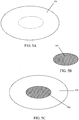
- the contact layer of the tissue therapy device comprises a stacked mesh matrix.
- the stacked mesh matrix comprises at least two mesh matrix sheets.
- the stacked mesh matrix comprises multiple mesh matrix sheets.
- the stacked mesh matrix may be adapted and configured to provide fluid communication between the suction apparatus and an area of tissue which requires treatment.
- the contact layer of the tissue therapy device comprises an adjustable micro-particles pouch.
- the micro-particles and the pouch may be adapted and configured to provide fluid communication between the suction apparatus and the area of tissue requiring treatment.
- the micro-particles are made from a polymer material.
- the pouch contains at least two particles.
- the pouch volume can be adjusted by adding or subtracting micro-particles from the pouch without disturbing the integrity of the pouch.
- the contact layer may be prefabricated to a specific size and shape. In another embodiment, the contact layer may be prefabricated to a specific size and shape and then cut so that the prefabricated contact layer conforms to the shape or size of the wound.
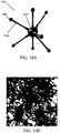
- the stacked mesh matrix comprises a series of thin filaments.
- the filaments are made from a polymer material.
- the filaments of the stacked mesh matrix may be oriented such that the filaments lie perpendicular to one another. In some embodiments the filaments are randomly oriented. In some embodiments, the filaments are between approximately 0.001 mm to approximately 10 mm thick. In some embodiments, the filaments are more than approximately 0.01 mm thick. In some embodiments the filaments are more than approximately 0.05 mm thick. In some embodiments, the filaments are more than approximately 0.1 mm thick. In some embodiments the filaments are more than approximately 0.5 mm thick.
- the filaments are more than approximately 1 mm thick. In some embodiments the filaments are more than approximately 2.5 mm thick. In some embodiments, the filaments are approximately more 5 mm thick. In some embodiments, the filaments are approximately more than 7.5 mm thick. In some embodiments, the filaments are approximately more than 10 mm thick. In some embodiments, the filaments are less than approximately 10 mm thick. In some embodiments, the filaments are less than approximately 5 mm thick. In some embodiments the filaments are less than approximately 1 mm thick. In some embodiments, the filaments are less than approximately 0.05 mm thick. In some embodiments the filaments are less than approximately 0.01 mm thick. In some embodiments the filaments are less than approximately 0.005 mm thick. In some embodiments, the filaments are less than 0.001 mm thick. In some embodiments, all the filaments throughout the stacked mesh matrix are of a uniform thickness. In other embodiments, the filament thickness is variable throughout the stacked mesh matrix.
- a mesh matrix sheet comprises filaments that are spaced between approximately 1 mm to 15 mm apart. In some embodiments the filaments are spaced more than about 1 mm apart. In some embodiments the filaments are spaced more than about 2 mm apart. In some embodiments the filaments are spaced about 4 mm apart. In some embodiments the filaments are spaced about 6 mm apart. In some embodiments the filaments are spaced about 8 mm apart. In some embodiments the filaments are space about 10 mm apart. In some embodiments the filaments are spaced about 12 mm apart. In some embodiments the filaments are spaced about 15 mm apart. In other embodiments the filaments are spaced between approximately 1 mm to approximately 5 mm apart.
- the filaments are spaced between approximately 5 mm to 10 mm apart. In some embodiments the filaments are spaced approximately 10 mm to 15 mm apart. In some embodiments, the filaments are spaced uniformly throughout the stacked mesh matrix. In other embodiments, the filaments are variably spaced throughout the stacked mesh matrix.
- the stacked mesh matrix of the wound dressing may be designed to include other features.
- the stacked mesh matrix can deliver biologics to the wound through the filaments of a delivery mesh.
- the filaments of the delivery mesh are solid filaments soaked in a solution containing biologics or therapeutics.
- the filaments of the delivery mesh are hollow. Examples of biologics to facilitate wound healing include, but are not limited to, antibiotics and growth factors.
- the delivery mesh may be used to irrigate the wound. In some embodiments where a delivery mesh is used, a separate external fluid source may be connected to the delivery mesh.
- the stacked mesh matrix comprises a single mesh matrix sheet. In another embodiment, the stacked mesh matrix comprises more than two or multiple mesh matrix sheets to create a multi-layered dressing. In this embodiment, the stacked mesh matrix may be separated to a desired thickness based on the thickness of the wound. In a further embodiment, the stacked mesh matrix may include a delivery mesh layer. In some embodiments, the delivery mesh is located on the bottom of the stacked mesh matrix. In some embodiments, the delivery mesh is located at the top of the stacked mesh matrix. In some embodiments, the delivery mesh is located anywhere but at the top or bottom of the stacked mesh matrix.
- a method for applying reduced pressure therapy to an area of tissue comprising creating a sealed enclosure around an area of tissue to be treated by affixing a sealant layer to a surface of a patient. Reduced pressure is then self-created underneath the sealant layer by expanding a volume of the enclosure using a suction apparatus in fluid communication with the enclosure created by the sealant layer.
- the method uses a closed reduced pressure therapy system, comprising a sealant layer and a suction apparatus.
- the sealed enclosure is air-tight.
- the method further comprises providing a contact layer on the wound surface before the sealant layer is affixed to the surface of the patient.
- the method further comprises applying a protective layer around the area of the tissue to be treated before creating the sealed enclosure. In some embodiments the method further comprises applying a hydrocolloid to the area of tissue to be treated. In some embodiments of the method described herein, the method further comprises creating reduced pressure with an external suction apparatus.
- a method of treating a wound using a reduced pressure therapy device comprising creating a sealed enclosure between a sealant layer of a wound dressing and the surface of a patient and applying self-created reduced pressure to a wound by forcefully expanding a volume of air molecules enclosed in the sealed enclosure.
- the method uses a closed reduced pressure therapy system.
- the wound to be treated is selected from an acute wound, a partial- or full-thickness burn, a surgically created wound or surgical dehiscence, neuropathic (diabetic) wounds, venous or arterial insufficiency ulcers, traumatic wounds, and pressure ulcers, and any other wound or damaged tissue for which the application of reduced pressure therapy is suitable.
- a method of treating an area of damaged tissue using reduced pressure tissue therapy comprising positioning a reduced pressure tissue therapy device over an area of tissue to be treated, where the reduced pressure tissue therapy device comprises a sealant layer and a suction apparatus, and reducing the level of pressure in a volume of air located under the sealant layer by engaging the suction apparatus, where the suction apparatus self-creates the reduction in pressure by forcefully expanding the volume of air.
- the sealant layer and the suction apparatus form a closed reduced tissue therapy system.
- the method further comprises decreasing the density of air molecules under the sealant layer to create reduced pressure.
- Fig. 1A illustrates one embodiment of a tissue therapy device 100.
- Fig. 1A shows a wound dressing 102 and a suction apparatus 104.
- the wound dressing 102 comprises a sealant layer 108.
- the wound dressing further comprises a contact layer.
- the contact layer provides fluid communication between the wound and the suction apparatus.
- the contact layer may comprise a foam, a mesh, a gauze, a sponge, a particulate matter, a stacked mesh matrix, or any other suitable biocompatible material or biocompatible porous structure, or any combination thereof.
- the contact layer may be placed in contact with the wound surface. Once positioned, the contact layer is then covered by the sealant layer 108.
- the contact layer is placed separately on the wound followed by the placement of the sealant layer.
- the contact layer and the sealant layer are integrated together to streamline application of the wound dressing.
- the sealant layer may be affixed to the surface of the patient surrounding the wound by any suitable adhesive means known to one skilled in the art.
- adhesives may include, but are not limited to, tape, glue, or a suitable biocompatible adhesive product.
- a suction apparatus 104 self-creates reduced pressure underneath the sealant layer 108 of the wound dressing 102.
- the suction apparatus 104 may also be used to collect any exudate or debris drawn up from the wound.
- the suction apparatus 104 comprises a collection chamber 120 having rigid sides 136 and a hollow interior.
- a sliding seal or fitted reciprocating mechanism 138 seals against the interior sides 140 of the collection chamber 120.
- the end of the reciprocating mechanism 142 may be engaged thereby increasing or decreasing the volume of the collection chamber 120. Engaging the end of the reciprocating mechanism 142 also creates reduced pressure within the wound dressing.
- the suction apparatus 104 of the wound therapy device 100 may be connected to the wound dressing 102 by way of a compression fitting 122.
- the compression fitting 122 provides a mechanism or structure for attaching the suction apparatus 104 to the sealant layer 108.
- the compression fitting 122 may comprise two or more components.
- Fig. 1A shows one of two attachment pieces 124 of the compression fitting 122 of the tissue therapy device 100.
- the attachment pieces of the compression fitting 122 may be configured to sandwich the sealant layer 108 such that one attachment piece 124 is underneath the sealant layer 108 and one attachment piece is above the sealant layer 108. The two attachment pieces are then secured together to hold the sealant layer between the attachment pieces.
- the attachment pieces are secured together with screws 126 as shown in Fig. 1A .
- the attachment pieces are secured together with an adhesive.
- Other securing mechanisms include but are not limited to mechanical interfits including snapfits, frictional interfits, welding, heat melding, and the like.
- the attachment piece 124 is made from acrylic.
- the attachment piece is made from, but not limited to, silicon, metal, or polymer materials, plastic, or any other suitable biocompatible material.
- the device has two attachment pieces.
- the attachment piece is a single piece, such as a single piece of molded silicon.
- An aperture 125 in the middle of the attachment pieces allows for communication between the wound and the suction apparatus.
- the suction apparatus 104 may be attached to the attachment piece 124 of the compression fitting 122 using a compression gasket 128.
- the compression gasket 128 may be inserted into the aperture 125 in the middle of the attachment pieces 124.
- the suction apparatus 104 is attached to the compression gasket 128 by inserting the neck of the suction apparatus 104 into a stem 132 of the compression gasket 128.
- the suction apparatus 104 may be attached to the compression gasket 128 by inserting the suction apparatus 104 into the compression gasket 128.
- the suction apparatus 104 may be attached to the compression gasket 128 by screwing the suction apparatus 104 into the stem 132 of the compression gasket 128.
- the suction apparatus 104 may be easily detached and reattached if desired or required.
- the tissue therapy device comprises a compression gasket 128 equipped with at least one stem 132 for attaching the suction apparatus.
- the compression gasket may have a second connector 133 as shown in Fig. 1A .
- the connector 133 may be used for attaching a second suction apparatus.
- the connector 133 may be used to attach a separate external collection chamber.
- the suction opening in the tissue dressing may be pre-formed, but in some other embodiments, the suction opening may be formed at the point-of-use.
- the dressing may comprise perforations, regions of reduced thickness, or other structural features that may be provided to facilitate formation of a suction opening.
- more than one suction opening may be formed in the dressing, and more than one suction aperture forming structure may optionally provided.
- the wound therapy device incorporates a three-way valve 134.
- the valve In one position, the valve allows exudate to be drawn up from the wound into the suction apparatus. In a second position the valve closes the communication between the wound dressing and the suction apparatus such that reduced pressure is maintained during emptying or replacement of the suction apparatus. In a third position, the valve allows fluid communication between the suction apparatus and an external collection chamber, while preventing exudate from returning to the wound surface.
- Figure 1B shows an illustration of one embodiment of a wound dressing 102 of the tissue therapy device.
- the sealant layer 108 of the wound dressing comes in contact with the surface of the patient around the perimeter of the wound.
- Fig. 1B further illustrates a hole 130 in the middle of the wound dressing 102.
- One attachment piece is positioned on one side of the hole and another attachment piece is positioned on the other side of the hole as shown in Fig. 1A .
- the compression gasket is then attached to the attachment pieces as shown in Fig. 1A .
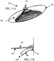
- Fig. 11A depicts another embodiment of a wound dressing 750.
- the wound dressing 750 comprises a sealing film 752 with an adhesive region 754 located along the perimeter of the sealing film 752.
- Located on the inner surface 756 of the sealing film 752 is a contact layer 758, while a suction connector 760 is located on the outer surface 762 of the sealing film 752.
- the contact layer 758 depicted in Figs. 11A and 11B comprises a sponge material, but other contact layer materials or combinations of materials may also be used. As shown in Fig.
- the contact layer 758 has a central portion 764 that is in contact with the inner surface 756 of the sealing film 752, and a perimeter portion 766 that is unattached from the inner surface 762 of the sealing film 752.
- the central portion 764 of the contact layer 758 is glued or otherwise attached to the inner surface 762 of the sealing film 752, while in other embodiments the contact layer 758 is connected to the suction connector 760 without any specific attachment to the sealing film 752.
- the contact layer 758 may be substantially unattached to the sealing film 752, while in other embodiments, the rigidity or geometry of the contact layer 758 maintains a significant portion of the contact layer 758 against the sealing film 752 without any adhesive or other securing mechanisms.
- the contact layer 758 is pre-formed with a generally concave shape that biases the perimeter portion 766 of the contact layer 758 away from the sealing film 752. In other embodiments, however, the contact layer 758 may be configured with a generally convex or any other configuration. In some embodiments, the contact layer 758 is pre-formed with a generally planar configuration, but is sufficiently flexible such that when dry or when wet, gravity is sufficient to flex the perimeter portion 766 of the contact layer 758 away from sealing film 752. In some embodiments, the surface 768 of the perimeter portion 766 adjacent the sealing film 752 may be provided with a non-stick surface to resist adhesion to the adhesive region 754 of the sealing film 752.
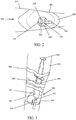
- the tissue therapy device 200 is used by applying the wound dressing 202 of the device 200 to a patient 210 over a wound.
- the distal side of the sealant layer 208 together with the compression fitting 222 as placed on the patient is seen in Fig. 2 .
- the attachment pieces are attached to the sealant layer prior to placing the wound dressing on the patient.
- the attachment pieces are attached to the sealant layer after the sealant layer has been positioned on the patient.
- the attachment pieces are secured together using screws 226.
- the attachment pieces are secured together using any suitable means available to fasten the attachment pieces together.
- the compression gasket is already integrated with the attachment pieces.
- a three-way valve 234 is integrated with the compression fitting 222 as shown in Fig. 2 .
- the three-way valve 234 may be used in any means previously described.
- the three-way valve 234 may be set to the open position for exudate to flow into the collection chamber of the suction apparatus.
- the suction apparatus is then connected to the stem 232 of the compression gasket 228.
- an external additional suction apparatus may be attached to the device via a second connection stem 233.
- an external collection chamber may be attached to the device by attaching the external collection chamber to the second connection stem 233.
- a reduced pressure tissue therapy device 300 wherein the tissue therapy device is portable.
- the portability of the device allows the patient to remain mobile during use.
- the wound dressing 302 is placed over the wound of the patient.
- Fig. 3 shows a patient 310 having a wound in which the tissue therapy device 300 has been placed over the wound.
- a suction apparatus 304 is attached to the wound dressing by the stem 332 on the compression fitting.
- the suction apparatus is already attached to the wound dressing. Reduced pressure may be created by engaging the end 342 of the reciprocating mechanism 338 of the suction apparatus 304.
- the suction apparatus 304 is unmarked; the suction apparatus has no markings to identify different strengths of, or settings corresponding to, levels of reduced pressure.
- the suction apparatus 304 is marked with markings 305, as shown in Fig. 3 , indicating different positions for the reciprocating mechanism to be drawn back to, creating different set levels of negative pressure as shown in Fig. 3 .
- Exudate drawn from the wound is drawn into the collection chamber 320 when the three-way valve 334 is opened.
- the collection chamber 320 is the same as the suction apparatus 304.
- the suction apparatus 304 may be secured to the patient 310 by any means suitable for adhering the device to the patient 310.
- the suction apparatus 304 is adhered to the patient with tape 344, as shown in Fig. 3 .
- the suction apparatus is secured to a patient, with elastic bands, VELCRO® straps, adhesive bandages, gauze, or cloth strips, or any other suitable means for securing the suction apparatus to the patient.
- the suction apparatus 404 comprises a ratcheting mechanism.
- the reciprocating mechanism 438 of the suction apparatus 404 is engaged using a handle 458, as shown in Fig. 4 .
- the reciprocating mechanism 438 is drawn back to create reduced pressure and the reduced pressure is maintained using resistance between the reciprocating mechanism and the interior walls of the syringe.
- the reciprocating mechanism 438 is engaged to create reduced pressure and the reduced pressure is maintained by holding the reciprocating mechanism 438 in the position to which it is drawn back to using interlocking teeth 460 on the shaft 446 and the body 456 of the suction apparatus 404, as shown in Fig. 4 .
- Fig. 4 also shows a means for securing the suction apparatus to the patient, in the form of a strap 445 integrated into the body 456 of the suction apparatus 404.
- a helical threaded interface is provided between the actuator (e.g. plunger) and the suction chamber. To provide suction, the actuator may be rotated to move the sliding seal or reciprocating mechanism and to generate a reduced pressure.
- the helical threaded interface may be located on an internal surface of the suction chamber and an outer surface of the actuator. In other embodiments, the threaded interface may be located on the outer surface of the suction chamber and an inner surface of an interface member coupled to the actuator or plunger.
- a clamp or an interference structure such as a retaining pin, may be used to maintain the position of the sliding seal or reciprocating mechanism.
- the suction apparatus is attached directly to the wound dressing, as shown in Fig. 1A .
- a suction apparatus 462 with a ratcheting assembly 464 and a securing strap 466 is coupled to a wound dressing 468 using a valve 470.
- the wound dressing 468 comprising a sealing layer 472 and a foam contact layer 474, but in other embodiments, a different contact layer material may be used.
- Other examples of contact layer materials are disclosed elsewhere herein.
- the sealing layer 472 may comprise any of a variety of materials, including but not limited to a polyethylene or polyurethane, for example.
- the sealing layer 472 may also include any of a variety of other components or coatings, including an acrylate polymer as included in TEGADERM® polyethylene dressing.
- the suction apparatus 404 is attached to a wound dressing by a tube 472, as shown in Fig. 4 .
- a tube 472 is attached to an outlet port 403 of the wound dressing 402.
- the other end of the tube 472 is then attached to the suction apparatus 404 by a three-way valve 434.
- the three-way valve 434 allows exudate to be drawn up from the wound into the collection chamber 420.
- the three-way valve 434 closes the communication between the wound dressing and the suction apparatus such that negative pressure is maintained during emptying or replacement of the suction apparatus.
- the three-way valve allows fluid communication between the suction apparatus 404 and an external collection chamber, while preventing exudate from returning to the wound.
- use of a flexible tube permits the placement of the suction apparatus at a different location from the sealing layer of the tissue dressing. This may be beneficial, for example, by securing the suction apparatus in at a distance from a treatment location with pre-existing vascular compromise which may be further compromised by a securing strap or band of the suction apparatus.
- the wound dressing and suction apparatus may be placed directly over the wound on the patient without any preparation of the patient and a seal is created between the sealant layer and the skin of the patient.
- a contact layer is positioned on the wound before the sealant layer is placed over the wound.
- the contact is placed on the wound as a separate structure after being trimmed to accommodate the shape of the wound.
- the contact layer is in contact only with the wound surface and not in contact with any area surrounding the wound.
- the contact layer is in contact with the tissue surrounding the wound.
- the contact layer is integrated into the sealant layer. In such an embodiment, the edges of the contact layer are not attached to the sealant layer and may be trimmed to accommodate the shape of the wound.
- the wound dressing and vacuum chamber manifold is placed directly over the wound on the patient without any preparation of the patient and a seal is created between the sealant layer of the wound dressing and the skin of the patient.
- the seal is broken and a new seal is formed has to be formed between the skin and the new wound dressing.
- a protective layer 574 is placed on the skin of the patient before the sealant layer of the wound dressing is put in contact with the skin of the patient, as shown in Fig. 5A .
- the protective layer is adhered to the skin of the patient using any suitable means for adhering the protective layer to the patient.
- the protective layer may include a pressure adhesive layer.
- the protective layer is prefabricated to a specified size or shape. In this embodiment, a protective layer is chosen such that is it larger than the size of the wound so that it can surround the perimeter of the wound. In some embodiments, the protective layer is adjusted to the size of the wound by a clinician.
- the protective layer 574 may be cut by a clinician to mimic or generally track the shape or size of the wound, such that the protective layer follows the perimeter of the wound. In some embodiments, the protective layer is smaller than the size of the wound.
- Figs. 5A and 5B show the protective layer 574 of Fig. 5A sized to fit the wound 590 shown in Fig. 5B . Once the protective layer is cut to the desired size or shape, the protective layer is placed on skin surface surrounding the wound 590, as shown in Fig. 5C .
- the protective layer 574 may comprise any of a variety of materials, including a polyurethane foam such as DUODERM®.
- the sealant layer of the wound dressing is positioned in contact with the protective layer.
- a seal is formed between the sealant layer of the wound dressing and the protective layer.
- the seal formed is airtight.
- the protective layer serves to protect the edges of the wound from maceration, decrease the pain and skin trauma resulting from dressing change, and to form a strong seal between the dressing and the skin.
- the sealant layer and protective layer provide a reliable seal for delivering reduced pressure tissue therapy.
- the protective layer may comprise an annular seal that may be placed around the wound area, rather than over the dressing.
- the dressing may be configured that could fit within the seal using a screw-in or a snap-in mechanism, for example. When the dressing is changed, the annular seal may remain fixed to the wound or treatment area while the dressing is replaced.
- the dressing may be attached to the seal around a central region of the seal while the edges of the dressing are generally not attached to the seal. In some of these embodiments, the dressing may be trimmed to generally accommodate the shape of the wound.
- an integrated contact layer and sealant layer 602 connected to a suction apparatus 604 of a reduced pressure tissue therapy device 600 is placed over the first protective layer 674 as shown in Fig. 6 .
- An airtight seal is formed between the integrated contact layer and sealant layer 602 and the protective layer 674.
- the protective layer 674 may be left in place and the integrated contact layer and sealant layer 602 changed approximately every three (3) to seven (7) days.
- the integrated contact layer and sealant layer 602 is changed about every four (4) days.
- the integrated contact layer and sealant layer 602 is changed about every five (5) days.
- the integrated contact layer and sealant layer 602 is changed about every six (6) days. In some embodiments, the integrated contact layer and sealant layer 602 is changed about every seven (7) days. In some embodiments, only a sealant layer is placed in contact with the protective layer.
- the protective layer in such an embodiment may be changed if there is a loss of adhesion between the protective layer and the skin of the patient. In some embodiments, the protective layer may be changed if the wound edges have migrated enough to warrant adjusting the protective layer to accommodate the changed size of the wound.
- Fig. 12 depicts another embodiment of a tissue therapy device 700, comprising a sealing layer 702 with a resealable interface 704.
- the resealable interface 704 may permit access to the tissue underneath the sealing layer 702, without requiring replacement of the sealing layer 702, or compromising the seal between the sealing layer 702 and the patient's skin. This may be beneficial, for example, for inspecting the treatment area, changing the contact layer, debriding a wound, and/or to applying any topical agents.
- the resealable interface 704 comprises a cap member 706 and a base member 708 attached to the sealing layer 702.
- the base member 708 comprises a resealable aperture 710 that is configured to form a complementary interfit with the cap member 706.
- the resealable aperture 710 and the cap member 706 comprises complementary threads 712 and 714, respectively.
- a snapfit or a latch may be provided to secure the cap member 706 to the base member 708.
- hinge or flexible elongate member may be provided to keep the cap member 706 attached to the base member 708.
- one or more gaskets may be provided on cap member 706 and/or the base member 708 to facilitate an airtight seal. In some embodiments, as shown in Fig.
- a contact layer 716 may be integrally formed with the cap member 706, such that when changing the contact layer 716, the cap member 706 is removed from the base member 708 and replaced with a new cap member 706 with contact layer 708.
- a suction aperture 718 is provided on the cap member 706 for attachment to a suction apparatus, but in other embodiments, the suction aperture may also be provided on the base member. In some embodiments, multiple suction apertures may be provided.
- the cap member 706 may optionally comprise one or more tab members 720 or other structures to facilitate opening and closing of the cap member 706.
- the base member 708 may also optionally comprise a tab member or other structure to stabilize the base member 708 while manipulating the cap member 706, which may reduce the risk of compromising the seal between the patient and the sealing layer 702.
- the contact layer of the wound dressing comprises a stacked mesh matrix.
- the stacked mesh matrix is shown in Figs. 7A and 7B .
- the stacked mesh matrix comprises one or more mesh matrix sheets 778 of thin filaments 776 as shown in Fig. 7A .
- the filaments are between approximately 0.001 mm to approximately 10 mm thick. In some embodiments, the filaments are more than approximately 0.01 mm thick. In some embodiments the filaments are more than approximately 0.05 mm thick. In some embodiments, the filaments are more than approximately 0.1 mm thick. In some embodiments the filaments are more than approximately 0.5 mm thick. In some embodiments, the filaments are more than approximately 1 mm thick.
- the filaments are more than approximately 2.5 mm thick. In some embodiments, the filaments are approximately more 5 mm thick. In some embodiments, the filaments are approximately more than 7.5 mm thick. In some embodiments, the filaments are approximately more than 10 mm thick. In some embodiments, the filaments are less than approximately 10 mm thick. In some embodiments, the filaments are less than approximately 5 mm thick. In some embodiments the filaments are less than approximately 1 mm thick. In some embodiments, the filaments are less than approximately 0.05 mm thick. In some embodiments the filaments are less than approximately 0.01 mm thick. In some embodiments the filaments are less than approximately 0.005 mm thick. In some embodiments, the filaments are less than 0.001 mm thick.
- the filaments throughout the stacked mesh matrix are of a uniform thickness. In other embodiments, the filament thickness is variable throughout the stacked mesh matrix.
- the filaments may be made of any suitable biocompatible material known in the art, such as polymer.
- the filaments 776 are less than 10 mm thick. In some aspects, the filaments are approximately 0.001 mm to approximately 10 mm thick.
- the filaments within a single mesh matrix sheet 778 have the same uniform thickness. In some embodiments, the filaments within a single mesh sheet 778 have variable thickness within the sheet.
- the filaments 776 of the mesh matrix sheet 778 may be oriented such that they lie perpendicular in orientation to one another, or at some other angle. In other embodiments, the filaments may be oriented randomly within the sheet.
- the stacked mesh matrix comprises mesh matrix sheets where the filaments of the mesh matrix sheet are spaced between approximately 1 mm to 15 mm apart. In some embodiments the filaments are spaced more than about 1 mm apart. In some embodiments the filaments are spaced more than about 2 mm apart. In some embodiments the filaments are spaced about 4 mm apart. In some embodiments the filaments are spaced about 6 mm apart. In some embodiments the filaments are spaced about 8 mm apart.
- the filaments are space about 10 mm apart. In some embodiments the filaments are spaced about 12 mm apart. In some embodiments the filaments are spaced about 15 mm apart. In other embodiments the filaments are spaced between approximately 1 mm to approximately 5 mm. In some embodiments the filaments are spaced between approximately 5 mm to 10 mm apart. In some embodiments the filaments 776 are spaced approximately 10 mm to 15 mm apart. In some embodiments, the filaments 776 are spaced uniformly throughout the mesh matrix sheet 778. In some embodiments, the filaments 776 are variably spaced throughout the mesh matrix sheet. In some aspects, the spacing between filaments is variable. In some aspects the filaments 776 may be hollow.
- Each of the mesh structures may have a uniform or a non-uniform size, shape or configuration with respect to the other mesh structures.
- one or more sheets may have a generally planar configuration, but in other embodiments, one or more sheets may have a non-planar configuration.
- the edges of a mesh sheet may comprise the ends of the tubes that comprise the mesh sheet.
- the mesh sheet may be configured with an annular edge comprising one or more tubes. In some embodiments, the annular edge may reduce the degree of tissue response to the mesh sheet compared to an edge comprising tube ends.
- the mesh sheet may be rigid, semi-rigid, or flexible.
- the degree of flexibility may vary depending upon the degree of hydration of the mesh sheet.
- the degree of flexibility may be isotropic or anisotropic.
- one or more mesh sheets may have a generally planar configuration, while in other embodiments, one or more mesh sheets may have a curved, corrugated, egg-crated shape, or other non-planar configuration.
- the mesh matrix may comprise be arranged so that the configurations or orientations of adjacent mesh sheets are non-uniform. In embodiments where the mesh sheets are non-planar, small spaces may be formed between the adjacent mesh sheets.
- the sheets may be adherent or non-adherent to each other with contact.
- the filaments comprising a mesh sheet may be configured to have a length extending from one edge of a sheet to another edge of the sheet.
- one or more filaments may have a length and orientation where the filaments ends are not located at an edge of the sheet.
- the filaments may have any of a variety of cross-sectional shapes, including but not limited to circles, ovals, squares, rectangles, triangles or any other polygonal or closed-ended shape.
- the cross-sectional shape or cross-sectional area of a filament need not be uniform along its longitudinal length.
- a mesh sheet may further comprise a non-tubular or non-elongate structure, such as a disc or a cube.
- the non-tubular structures may comprise the same or a different material.
- one or mesh sheets may comprise one or more biodegradable or bioabsorbable materials.
- the biodegradable materials may be metallic or non-metallic, including but not limited to biodegradable polymers.
- examples of such polymers include but are not limited to various forms of polycaprolactone, poly (Llactide)s, poly(DL-lactide)s, polyglycolide, poly(L-lactide-co-D, L-lLactide), Poly (DL-lactide-co-glycolide), poly(DL-lactide-co-caprolactone), polydioxanone , polyesteramide, copolyoxalate, poly (glutamic-co-leucine), and combinations thereof.
- the substructures themselves may also have a surface porosity.
- the pores may substantially uniform or non-uniform in size, shape and/or configuration.
- the average surface porosity of a tube for example, may be about 1 nm to about 500 ⁇ m or more, sometimes about 5 nm to about 100 ⁇ m, and other times about 50 nm to about 500 nm.
- the contact layer may comprise one or more non-sheet structures.
- the contact layer may comprise a plurality of small, loose structures or particles that may have a generally two-dimensional or three-dimensional configuration.
- the non sheet structures may be packed into a porous pouch so as to enables easy placement and replacement of the non sheet structures from the damaged tissue cavity.
- These non-sheet structures may be used with or without mesh sheets.
- the non-sheet structures may have any of a variety shapes, including but not limited to filaments, chips, ball, cube, conical, frusto-conical or pyramidal shapes, for example. Some of the shapes may have a complex, three-dimensional configuration. In Fig.
- the non-sheet structure or particle 1000 may comprise a plurality of appendages or tubes 1002 have one or more convergent sites 1004.
- the tubes 1000 have any of a variety of features as described for the tubes comprising the mesh sheets.
- Fig. 10B depicts one embodiment of the aggregation of a plurality of particle 1000.
- the overall structure comprises a porous, three-dimensional matrix which should be preferably packed into a porous pouch.
- each of the particles may have an overall average dimension of about 0.5 mm to about 20 mm, sometimes about 5 mm to about 15 mm, and other times about 3 mm to about 7 mm.
- the aggregate porosity of the matrix formed may vary, depending on the length and thickness of the tubes 1002.
- the length and thickness of tubes 1002 may be uniform or non-uniform on the same particle or between different particles.
- the tubes 1002 depicted in Fig. 10A comprise ball-shaped end structures 1006, but in other embodiments, end structures of other shapes may be provided, or end structures may be omitted on one or more tubes 1002.
- particles 1000 may be pre-hydrated outside the wound or tissue treatment area and allowed to adhere to each other.
- the three-dimensional matrix formed by the particles may be pre-shaped prior to placement at the tissue treatment site, or packed into a porous pouch. Other pouch-based embodiments are described in greater detail below.
- the stacked mesh matrix 779 comprises at least two mesh matrix sheets 778. In some embodiments, the stacked mesh matrix 779 will comprises two mesh matrix sheets 778 of Fig. 7A . In an alternate embodiment, the wound dressing comprises multiple mesh matrix sheets 778 as shown in Fig. 7B . In some embodiments, the individual mesh matrix sheets that are stacked together to form a stacked mesh matrix have the same filament thickness and the same filament spacing as the other mesh matrix sheets comprising the stacked mesh matrix. In some embodiments, the individual mesh matrix sheets that are stacked together to form a stacked mesh matrix have different filament thickness and different filament spacing as compared to the other mesh matrix sheets comprising the stacked mesh matrix.
- the single sheets 778 are adhered together to form the stack mesh matrix 779, but can be peeled apart so that the height of the dressing can be adjusted to the depth of the wound.
- the size of the communicating pathways 777 depends on the stack depth and filament spacing and can be configured to different sizes depending on the drainage needs of the wound.
- the reduced pressure tissue therapy device may include a delivery mesh to provide variable-pressure assisted irrigation or delivery of biologics to the wound.
- the delivery mesh comprises filaments that are soaked with the solution to be delivered. In such an embodiment, the solution diffuses into the wound area from the filaments.
- the reduced pressure tissue therapy device comprises a network of interconnected hollow tubes 813 arranged in a mesh-like configuration to form a delivery mesh 812, as seen in Fig. 8 .
- the delivery mesh 812 is placed over the wound 890.
- the delivery mesh is sealed underneath the sealant layer 802 of the wound dressing of the reduced pressure tissue therapy device.
- the network of hollow tubes 813 may be perfused with a solution.
- the solution contains antibiotics. In another aspect, the solution contains biologics, such as growth factors.
- the delivery mesh 812 described herein may be used to irrigate the wound. In some embodiments, the delivery mesh 812 described herein may be used with a reduced pressure tissue therapy device. In one embodiment, the delivery mesh 812 is sized and placed on the wound 890 of a patient 810.
- the delivery mesh 812 incorporates a supply tube 814 with a supply tube connector 815 at the end of the supply tube 814.
- the supply tube 814 is connected to a fluid supply reservoir through the supply tube connector 815.
- the supply tube 814 may be connected to the fluid supply reservoir by snapping the connector together. Alternatively, the supply tube and the fluid supply reservoir may be connected by screwing the connector together.
- the sealant layer 802 of the wound dressing of a reduced pressure tissue therapy device may be placed over the delivery mesh 812.
- the contact surface 806 of the wound dressing is in fluid communication with the delivery mesh and is placed over the delivery mesh 812 to apply reduced pressure to the wound surface.
- a delivery mesh for the delivery of biologics or antibiotics to the wound.
- a solution containing biologics or antibiotics, or a solution suitable for delivery to a wound may be delivered to the wound 990 from a fluid reservoir through a supply tube 914.
- the solution may be delivered to the wound through perforations 915 on the underside 916 of the delivery mesh 912 as seen in Fig. 9A .
- the perforations 915 provide fluid communication between the delivery mesh 912 and the wound 990.
- the delivery mesh 912 may be constructed into predetermined sizes where the size of the delivery mesh used depends on the size of the wound.
- the delivery mesh may be constructed such that the edges may be trimmed such that the delivery mesh is and adequate size for the wound surface.
- such a delivery mesh comprises hollow filaments.
- the delivery mesh may be trimmed and the hollow filaments may self-seal in the places where the delivery mesh is cut, such that fluid will not leak out of the ends.
- the hollow filaments of the delivery mesh will not self-seal when cut. In such an embodiment, solution will be able to reach the wound through the edges of the delivery mesh.
- the device and delivery mesh may be used in conjunction with a mechanical pump.
- the pump can deliver normal therapeutic reduced pressure, but may also be used to deliver positive therapeutic pressure to enhance distribution of solution to the wound.
- the delivery mesh 912 of Fig. 9A may be connected to an external infusion pump.
- the mechanical pump of the reduced pressure tissue therapy device could be set to apply positive pressure to the wound surface through a pressure delivery tube 918 in order to facilitate the delivery of the solution to the wound, as shown in Fig. 9B . After the infusion of solution through the infusion tube 917 is stopped (represented by X in Fig.
- the mechanical pump of the reduced pressure tissue therapy device can then be reversed so that reduced pressure is applied to the wound through the pressure delivery tube 918 ( Fig. 9C ).
- the infusion solution may be void of biologics and may serve to irrigate the wound and mobilize particles which the negative pressure could then remove from the wound bed.
- the delivery mesh may be designed such that the space between the filaments of the mesh would also serve as an area which supports wound in-growth.
- a sealed and evacuated bottle may be used as a vacuum source.
- the bottle may comprise a screw-in connector.
- the receptacle for the bottle on the dressing may comprise a mechanism or structure to break a seal on the bottle when the bottle is connected, thereby applying the negative pressure from the bottle to the wound or tissue treatment site.
- the particles may be placed or packed into one or more porous pouches, which may be placed into a tissue cavity.
- the particles may be loosely packed, permitting substantial movement of particles within the pouch, or tightly packed, where significant particle movement is limited due to particle density.
- the porosity of the pouch is smaller than the average size of the particles, but in other embodiments, the porosity of the pouch may be greater.
- one or more tubular structures may project out from the pores of the pouch but the particles do not separate from the pouch.
- the pouch is configured such that the particles or other components within the pouch may be released over time.
- the pouches are filled and sealed at the point-of-manufacture, while in other embodiments, the pouches are filled at the point-of-use.
- Figures 14A and 14B depict one embodiment of a pouch 1010 with a circular configuration and comprising a plurality of particles 1012 or structures.
- the pouch 1010 is filled and sealed at the point of manufacture and is not configured to be reopened.
- the pouch 1010 comprises two layers of edge-sealed porous materials 1014, 1016, but in other embodiments, may comprise a single layer of porous material folded onto itself and sealed against itself. The two layers of porous materials need not comprise the same material or have the same porosity characteristics.
- a mesh pouch 1018 is provided with a sealable opening 1020.
- the opening upon sealing of the sealable opening 1020, the opening is not configured to be reopened without damaging the pouch.
- the sealable opening 1020 is a resealable opening 1020, and may be reopened and may be emptied, refilled or topped off with particles or structures.
- the sealable opening 1020 comprises a flap 1022 with an adhesive 1024, but in other embodiments, any of a variety of sealable or resealable openings may be provided, including but not limited to a heat sealable flap opening, a pursestring opening, a zipper-type opening, a snap-fit opening, a hook-and-loop type of opening, etc.
- the pouch 1018 may be pre-filled at the point-of-manufacture with the particles or may be empty.
- the pouches may have any of a variety of shapes, including but not limited to circles, tapered discs, balls, ovals, ovules, rectangles, squares, boxes, and the like.
- the pouch may have an adjustable shape.
- the pouch 1026 depicted in Figure 15 comprises a sealable opening 1028 located at an edge of the pouch
- the pouch 1026 comprises an opening 1028 that is located away from the pouch edge 1030.
- the opening 1028 comprises a duck bill valve in which a syringe or other elongate member may be inserted to add or remove cover layer structures.
- the pouch may be filled with a variable amount of particles or contact layer structures.
- the structure of the pouch may be adjusted to different fill volumes.
- the pouch 1018 depicted in Figure 15 may be sealed at one location 1032 if substantially full, or may folded and sealed at a second location 1034 if filled with a substantially smaller volume.
- the flap 1022 may be folded over the distal end 1036 of the pouch 1018 and sealed on the other side of the pouch 1018.
Landscapes
- Health & Medical Sciences (AREA)
- Heart & Thoracic Surgery (AREA)
- Animal Behavior & Ethology (AREA)
- Biomedical Technology (AREA)
- Vascular Medicine (AREA)
- Life Sciences & Earth Sciences (AREA)
- Engineering & Computer Science (AREA)
- General Health & Medical Sciences (AREA)
- Public Health (AREA)
- Veterinary Medicine (AREA)
- Anesthesiology (AREA)
- Hematology (AREA)
- Media Introduction/Drainage Providing Device (AREA)
- Surgical Instruments (AREA)
Claims (10)
- Gewebetherapievorrichtung, umfassend:eine Abdichtungsschicht (302), wobei die Abdichtungsschicht konfiguriert ist, um einen abgedichteten Einschluss um einen Gewebebereich zu kreieren, der eine Therapie benötigt; undeine Absaugeinrichtung (304), wobei die Absaugeinrichtung durch die Abdichtungsschicht hindurch in Fluidverbindung mit dem Einschluss steht, wobei die Absaugeinrichtung konfiguriert ist, um selbst eine reduzierte Druckstufe innerhalb des Einschlusses zu kreieren und die Absaugeinrichtung konfiguriert ist, um tragbar zu sein;wobei die Absaugeinrichtung eine geschlossene Absaugkammer mit feststehenden Wänden umfasst, einen sich hin- und herbewegenden Mechanismus, um ein Volumen der Absaugkammer, die sich in Fluidverbindung mit dem Einschluss befindet, zu ändern, ein Stellglied, ein Einweg-Strömungsventil (234), das angepasst und konfiguriert ist, um zu verhindern, dass Fluid in den Gewebebereich, der eine Therapie benötigt, zurückkehrt, und eine spiralgewindete Schnittstelle zwischen dem Stellglied und der Absaugkammer, wobei die spiralgewindete Schnittstelle dazu dient, eine Position des hin- und herbewegenden Mechanismus zu erhalten, und wobei das Stellglied drehbar ist, um den hin- und herbewegenden Mechanismus zu bewegen, um Unterdruck zu erzeugen.
- Vorrichtung nach Anspruch 1, wobei die Absaugeinrichtung (304) nicht elektrisch angetrieben und konfiguriert ist, um ein Luftvolumen, das sich in einem Fugenvolumen eines Raumes befindet, der zwischen dem abgedichteten Einschluss und dem variablen Volumenabschnitt der Absaugeinrichtung geteilt wird, zu expandieren.
- Vorrichtung nach einem der Ansprüche 1 oder 2, wobei die Absaugeinrichtung (304) weiter konfiguriert ist, um eine Stufe einer Druckverringerung aufrecht zu erhalten, die geringer als etwa 250 mmHg ist.
- Vorrichtung nach einem der Ansprüche 1 bis 3, weiter umfassend entweder:eine externe Auffangkammer; odereine zweite Absaugeinrichtung.
- Vorrichtung nach einem der Ansprüche 1 bis 4, wobei entweder:die Absaugeinrichtung (304) und die Abdichtungsschicht (302) in eine einzige Struktur integriert sind; oderdie Absaugeinrichtung (304) angepasst und konfiguriert ist, um von der Abdichtungsschicht (302) abgesteckt und wieder daran angesteckt zu werden, ohne die Abdichtungsschicht (302) zu unterbrechen.
- Vorrichtung nach einem der Ansprüche 1 bis 5, weiter umfassend eine zweite Absaugeinrichtung, wobei die zweite Absaugeinrichtung angepasst und konfiguriert ist, um an der Abdichtungsschicht (302) angesteckt zu werden.
- Vorrichtung nach einem der Ansprüche 1 bis 6, weiter umfassend ein Befestigungselement (344), das konfiguriert ist, um die Absaugeinrichtung an einem Patienten anzubringen.
- Vorrichtung nach einem der Ansprüche 1 bis 7, weiter eine Kontaktschicht umfassend.
- Vorrichtung nach Anspruch 8, wobei die Kontaktschicht eine gestapelte Maschenmatrix ist.
- Vorrichtung nach einem der Ansprüche 1 bis 9, weiter umfassend eine Schutzschicht (574), die um den Gewebebereich, der zu behandeln ist, herum platziert ist.
Priority Applications (1)
| Application Number | Priority Date | Filing Date | Title |
|---|---|---|---|
| EP19155765.1A EP3513820B1 (de) | 2007-03-14 | 2008-03-13 | Vorrichtungen zur anwendung einer unterdrucktherapie |
Applications Claiming Priority (3)
| Application Number | Priority Date | Filing Date | Title |
|---|---|---|---|
| US90672107P | 2007-03-14 | 2007-03-14 | |
| US97308607P | 2007-09-17 | 2007-09-17 | |
| PCT/US2008/003412 WO2008112304A1 (en) | 2007-03-14 | 2008-03-13 | Devices and methods for application of reduced pressure therapy |
Related Child Applications (2)
| Application Number | Title | Priority Date | Filing Date |
|---|---|---|---|
| EP19155765.1A Division EP3513820B1 (de) | 2007-03-14 | 2008-03-13 | Vorrichtungen zur anwendung einer unterdrucktherapie |
| EP19155765.1A Division-Into EP3513820B1 (de) | 2007-03-14 | 2008-03-13 | Vorrichtungen zur anwendung einer unterdrucktherapie |
Publications (4)
| Publication Number | Publication Date |
|---|---|
| EP2129409A1 EP2129409A1 (de) | 2009-12-09 |
| EP2129409A4 EP2129409A4 (de) | 2014-07-23 |
| EP2129409B1 EP2129409B1 (de) | 2019-03-06 |
| EP2129409B2 true EP2129409B2 (de) | 2021-11-24 |
Family
ID=39759868
Family Applications (2)
| Application Number | Title | Priority Date | Filing Date |
|---|---|---|---|
| EP19155765.1A Active EP3513820B1 (de) | 2007-03-14 | 2008-03-13 | Vorrichtungen zur anwendung einer unterdrucktherapie |
| EP08726845.4A Active EP2129409B2 (de) | 2007-03-14 | 2008-03-13 | Vorrichtungen zur anwendung einer niederdrucktherapie |
Family Applications Before (1)
| Application Number | Title | Priority Date | Filing Date |
|---|---|---|---|
| EP19155765.1A Active EP3513820B1 (de) | 2007-03-14 | 2008-03-13 | Vorrichtungen zur anwendung einer unterdrucktherapie |
Country Status (3)
| Country | Link |
|---|---|
| US (5) | US10117977B2 (de) |
| EP (2) | EP3513820B1 (de) |
| WO (1) | WO2008112304A1 (de) |
Families Citing this family (133)
| Publication number | Priority date | Publication date | Assignee | Title |
|---|---|---|---|---|
| US9119705B2 (en) | 1998-06-08 | 2015-09-01 | Thermotek, Inc. | Method and system for thermal and compression therapy relative to the prevention of deep vein thrombosis |
| US8128672B2 (en) | 2006-05-09 | 2012-03-06 | Thermotek, Inc. | Wound care method and system with one or both of vacuum-light therapy and thermally augmented oxygenation |
| EP1646351B1 (de) | 2003-07-18 | 2011-03-30 | Thermotek, Inc. | Thermisches system für eine decke |
| US8574278B2 (en) | 2006-05-09 | 2013-11-05 | Thermotek, Inc. | Wound care method and system with one or both of vacuum-light therapy and thermally augmented oxygenation |
| US10058642B2 (en) | 2004-04-05 | 2018-08-28 | Bluesky Medical Group Incorporated | Reduced pressure treatment system |
| US10765785B2 (en) | 2004-07-19 | 2020-09-08 | Thermotek, Inc. | Wound care and infusion method and system utilizing a therapeutic agent |
| US10016583B2 (en) | 2013-03-11 | 2018-07-10 | Thermotek, Inc. | Wound care and infusion method and system utilizing a thermally-treated therapeutic agent |
| DE602007004546D1 (de) | 2006-09-28 | 2010-03-18 | Tyco Healthcare | Tragbares Wundtherapiesystem |
| US8323264B2 (en) | 2006-10-17 | 2012-12-04 | Bluesky Medical Group, Inc. | Auxiliary powered negative pressure wound therapy apparatuses and methods |
| WO2008112304A1 (en) | 2007-03-14 | 2008-09-18 | The Board Of Trustees Of The Leland Stanford Junior University | Devices and methods for application of reduced pressure therapy |
| GB0712764D0 (en) * | 2007-07-02 | 2007-08-08 | Smith & Nephew | Carrying Bag |
| ES2661762T3 (es) | 2007-10-10 | 2018-04-03 | Wake Forest University Health Sciences | Dispositivos para tratar el tejido de la médula espinal |
| US8246590B2 (en) | 2007-10-11 | 2012-08-21 | Spiracur, Inc. | Closed incision negative pressure wound therapy device and methods of use |
| GB0722820D0 (en) | 2007-11-21 | 2008-01-02 | Smith & Nephew | Vacuum assisted wound dressing |
| ES2555204T3 (es) | 2007-11-21 | 2015-12-29 | T.J. Smith & Nephew Limited | Dispositivo de succión y venda |
| MX2010005553A (es) | 2007-11-21 | 2010-06-01 | Smith & Nephew | Aposito para heridas. |
| ES2776709T3 (es) | 2007-11-21 | 2020-07-31 | Smith & Nephew | Apósito para heridas |
| GB2455962A (en) | 2007-12-24 | 2009-07-01 | Ethicon Inc | Reinforced adhesive backing sheet, for plaster |
| AU2009214439B2 (en) * | 2008-02-14 | 2014-09-25 | Solventum Intellectual Properties Company | Devices and methods for treatment of damaged tissue |
| WO2009111655A2 (en) | 2008-03-05 | 2009-09-11 | Kcl Licensing Inc. | Dressing and method for applying reduced pressure to and collecting and storing fluid from a tissue site |
| US8298200B2 (en) | 2009-06-01 | 2012-10-30 | Tyco Healthcare Group Lp | System for providing continual drainage in negative pressure wound therapy |
| US9033942B2 (en) | 2008-03-07 | 2015-05-19 | Smith & Nephew, Inc. | Wound dressing port and associated wound dressing |
| GB0804654D0 (en) | 2008-03-13 | 2008-04-16 | Smith & Nephew | Vacuum closure device |
| WO2009139893A1 (en) | 2008-05-15 | 2009-11-19 | Ossur Hf | Circumferential walker |
| KR101192947B1 (ko) * | 2008-05-30 | 2012-10-18 | 케이씨아이 라이센싱 인코포레이티드 | 가슴 조직에서 사용되는 감압,압축 장치 및 방법 |
| US8636709B2 (en) * | 2008-10-29 | 2014-01-28 | Northwestern University | Fluid containment apparatus |
| US9107985B2 (en) | 2008-10-29 | 2015-08-18 | Northwestern University | Wound treatment containment apparatus |
| EP3614114A1 (de) * | 2008-11-25 | 2020-02-26 | KCI Licensing, Inc. | Vorrichtung zur abgabe von reduziertem druck auf körperoberflächen |
| US8361043B2 (en) * | 2009-01-07 | 2013-01-29 | Spiracur Inc. | Reduced pressure therapy of the sacral region |
| US8454706B2 (en) | 2009-02-25 | 2013-06-04 | Brian C. de Beaubien | Antibiotic delivery system and method for treating an infected synovial joint during re-implantation of an orthopedic prosthesis |
| US8728045B2 (en) | 2009-03-04 | 2014-05-20 | Spiracur Inc. | Devices and methods to apply alternating level of reduced pressure to tissue |
| IL197854A0 (en) * | 2009-03-26 | 2009-12-24 | Yuval Cohen | Method and apparatus for releasably retaining bandages |
| EP2905037B1 (de) | 2009-04-10 | 2017-05-17 | KCI Licensing, Inc. | Geräte zur Verabreichung einer Vakuum-Wundtherapie auf eine geschlossene Schnittwunde |
| US8444614B2 (en) | 2009-04-10 | 2013-05-21 | Spiracur, Inc. | Methods and devices for applying closed incision negative pressure wound therapy |
| US20100324516A1 (en) | 2009-06-18 | 2010-12-23 | Tyco Healthcare Group Lp | Apparatus for Vacuum Bridging and/or Exudate Collection |
| US8961600B2 (en) | 2009-06-25 | 2015-02-24 | Optonol Ltd. | Method of using a fiber matrix for maintaining space in soft tissues |
| US8454907B2 (en) * | 2009-08-12 | 2013-06-04 | Orogen Holdings, Llc | Growth factor extractor |
| EP2335661B1 (de) * | 2009-12-18 | 2012-12-12 | Paul Hartmann AG | Zuschneidehilfe für Wundauflage zur Unterdrucktherapie |
| DK2515961T3 (da) | 2009-12-22 | 2019-07-15 | Smith & Nephew Inc | Apparatuses and methods for negative pressure wound therapy |
| US8500776B2 (en) | 2010-02-08 | 2013-08-06 | Covidien Lp | Vacuum patch for rapid wound closure |
| US8814842B2 (en) | 2010-03-16 | 2014-08-26 | Kci Licensing, Inc. | Delivery-and-fluid-storage bridges for use with reduced-pressure systems |
| US9061095B2 (en) | 2010-04-27 | 2015-06-23 | Smith & Nephew Plc | Wound dressing and method of use |
| USRE48117E1 (en) | 2010-05-07 | 2020-07-28 | Smith & Nephew, Inc. | Apparatuses and methods for negative pressure wound therapy |
| US11291760B2 (en) * | 2010-08-10 | 2022-04-05 | Kci Licensing, Inc. | Controlled negative pressure apparatus and alarm mechanism |
| US8753322B2 (en) | 2010-08-10 | 2014-06-17 | Spiracur Inc. | Controlled negative pressure apparatus and alarm mechanism |
| US8795246B2 (en) * | 2010-08-10 | 2014-08-05 | Spiracur Inc. | Alarm system |
| CA140188S (en) | 2010-10-15 | 2011-11-07 | Smith & Nephew | Medical dressing |
| CA140189S (en) | 2010-10-15 | 2011-11-07 | Smith & Nephew | Medical dressing |
| EP2654821B1 (de) | 2010-12-22 | 2019-05-08 | Smith & Nephew, Inc. | Vorrichtungen für unterdruckwundtherapie |
| USD714433S1 (en) | 2010-12-22 | 2014-09-30 | Smith & Nephew, Inc. | Suction adapter |
| GB2488749A (en) | 2011-01-31 | 2012-09-12 | Systagenix Wound Man Ip Co Bv | Laminated silicone coated wound dressing |
| CA2833232C (en) * | 2011-04-15 | 2018-05-22 | University Of Massachusetts | Surgical cavity drainage and closure system |
| GB201106491D0 (en) | 2011-04-15 | 2011-06-01 | Systagenix Wound Man Ip Co Bv | Patterened silicone coating |
| KR20140039024A (ko) * | 2011-06-07 | 2014-03-31 | 스미쓰 앤드 네퓨 피엘씨 | 상처 접촉 부재 및 방법 |
| US9681993B2 (en) * | 2011-06-07 | 2017-06-20 | Kci Licensing, Inc. | Solutions for bridging and pressure concentration reduction at wound sites |
| US10512587B2 (en) | 2011-07-27 | 2019-12-24 | Thermotek, Inc. | Method and apparatus for scalp thermal treatment |
| US10940047B2 (en) | 2011-12-16 | 2021-03-09 | Kci Licensing, Inc. | Sealing systems and methods employing a hybrid switchable drape |
| CN111419540A (zh) | 2011-12-16 | 2020-07-17 | 凯希特许有限公司 | 可释放的医用布单 |
| US11944519B2 (en) | 2012-01-18 | 2024-04-02 | Worldwide Innovative Healthcare, Inc. | Unbacked and modifiable tapes and skin dressings |
| AU2013209432B2 (en) | 2012-01-18 | 2016-11-17 | Worldwide Innovative Healthcare, Inc. | Modifiable occlusive skin dressing |
| US20130317443A1 (en) * | 2012-03-12 | 2013-11-28 | Ivwatch, Llc | Dressing for an Insertion Site of an Intravascular Infusate |
| US9675358B2 (en) | 2012-04-12 | 2017-06-13 | Wake Forest University Health Sciences | Conduit for peripheral nerve replacement |
| WO2013162728A1 (en) | 2012-04-24 | 2013-10-31 | Thermotek, Inc. | Method and system for therapeutic use of ultra-violet light |
| WO2014066724A1 (en) | 2012-10-26 | 2014-05-01 | Wake Forest University Health Sciences | Novel nanofiber-based graft for heart valve replacement and methods of using the same |
| EP3092990B1 (de) | 2012-11-16 | 2020-03-11 | KCI Licensing, Inc. | Verfahren zur herstellung eines medizinischen abdecktuches mit musterklebeschichten |
| DE102012223399A1 (de) * | 2012-12-17 | 2014-06-18 | Paul Hartmann Ag | Zuschneidbarer Wundverband |
| GB201222770D0 (en) | 2012-12-18 | 2013-01-30 | Systagenix Wound Man Ip Co Bv | Wound dressing with adhesive margin |
| USD738487S1 (en) | 2013-01-28 | 2015-09-08 | Molnlycke Health Care Ab | Suction device for negative pressure therapy |
| US10300180B1 (en) | 2013-03-11 | 2019-05-28 | Thermotek, Inc. | Wound care and infusion method and system utilizing a therapeutic agent |
| USD764654S1 (en) | 2014-03-13 | 2016-08-23 | Smith & Nephew, Inc. | Canister for collecting wound exudate |
| US20140309497A1 (en) * | 2013-04-15 | 2014-10-16 | Clifford T. Solomon | Tissue protection/retraction system |
| US9393004B2 (en) * | 2013-04-15 | 2016-07-19 | Theodore C. Solomon | Tissue protection system and method |
| EP3033117A4 (de) * | 2013-08-20 | 2017-04-19 | Wake Forest University Health Sciences | Gewebereparaturvorrichtungen mit selbstorganisierten materialien |
| EP3046435B1 (de) | 2013-09-18 | 2020-04-15 | Ossur Iceland EHF | Einlegesohle für eine orthopädische vorrichtung |
| US9839548B2 (en) | 2013-09-25 | 2017-12-12 | Ossur Iceland Ehf | Orthopedic device |
| US9668907B2 (en) | 2013-09-25 | 2017-06-06 | Ossur Iceland Ehf | Orthopedic device |
| US9839549B2 (en) | 2013-09-25 | 2017-12-12 | Ossur Iceland Ehf | Orthopedic device |
| US9839550B2 (en) | 2013-09-25 | 2017-12-12 | Ossur Hf | Orthopedic device |
| US10946124B2 (en) | 2013-10-28 | 2021-03-16 | Kci Licensing, Inc. | Hybrid sealing tape |
| WO2015065615A1 (en) | 2013-10-30 | 2015-05-07 | Kci Licensing, Inc. | Absorbent conduit and system |
| WO2015065616A1 (en) | 2013-10-30 | 2015-05-07 | Kci Licensing, Inc. | Dressing with sealing and retention intereface |
| WO2015065612A1 (en) | 2013-10-30 | 2015-05-07 | Kci Licensing, Inc. | Condensate absorbing and dissipating system |
| EP3821859A1 (de) | 2013-10-30 | 2021-05-19 | 3M Innovative Properties Co. | Verband mit unterschiedlich grossen perforationen |
| EP3068481B1 (de) | 2013-11-11 | 2020-01-01 | Thermotek, Inc. | System zur wundbehandlung |
| WO2015089261A1 (en) | 2013-12-12 | 2015-06-18 | Ossur Hf | Outsole for orthopedic device |
| EP3848009B1 (de) * | 2014-02-28 | 2025-07-23 | Solventum Intellectual Properties Company | Hybridabdecktuch mit einem perforierten gelbeschichteten netz |
| US11026844B2 (en) | 2014-03-03 | 2021-06-08 | Kci Licensing, Inc. | Low profile flexible pressure transmission conduit |
| USD742017S1 (en) | 2014-03-27 | 2015-10-27 | Ossur Hf | Shell for an orthopedic device |
| WO2015168681A1 (en) | 2014-05-02 | 2015-11-05 | Kci Licensing, Inc. | Fluid storage devices, systems, and methods |
| AU2015255726B2 (en) | 2014-05-09 | 2020-03-05 | Solventum Intellectual Properties Company | Disruptive dressing for use with negative pressure and fluid instillation |
| US10898217B2 (en) | 2014-05-09 | 2021-01-26 | Kci Licensing, Inc. | Dressing providing apertures with multiple orifice sizes for negative-pressure therapy |
| AU2015255723B2 (en) | 2014-05-09 | 2019-09-19 | Solventum Intellectual Properties Company | Dressing with contracting layer for linear tissue sites |
| CA2947298C (en) | 2014-05-09 | 2023-06-06 | Kci Licensing, Inc. | Debriding dressing for use with negative pressure and fluid instillation |
| USD764653S1 (en) | 2014-05-28 | 2016-08-23 | Smith & Nephew, Inc. | Canister for collecting wound exudate |
| USD764048S1 (en) | 2014-05-28 | 2016-08-16 | Smith & Nephew, Inc. | Device for applying negative pressure to a wound |
| USD764047S1 (en) | 2014-05-28 | 2016-08-16 | Smith & Nephew, Inc. | Therapy unit assembly |
| USD765830S1 (en) | 2014-06-02 | 2016-09-06 | Smith & Nephew, Inc. | Therapy unit assembly |
| USD770173S1 (en) | 2014-06-02 | 2016-11-01 | Smith & Nephew, Inc. | Bag |
| CN106535842B (zh) | 2014-06-05 | 2020-07-17 | 凯希特许有限公司 | 具有流体获取和分配特征的敷料 |
| EP3233001B1 (de) | 2014-12-17 | 2020-06-17 | KCI Licensing, Inc. | Verband mit entlastungsfähigkeit |
| US10391211B2 (en) | 2015-01-26 | 2019-08-27 | Ossur Iceland Ehf | Negative pressure wound therapy orthopedic device |
| FR3032349B1 (fr) * | 2015-02-10 | 2021-02-12 | Univ Centre Hospitalier | Orthese pour un traitement par depression des deformations en entonnoir du thorax |
| EP3574877B1 (de) | 2015-05-08 | 2022-08-17 | 3M Innovative Properties Company | Verband für geringe akuität mit integrierter pumpe |
| US10433965B2 (en) | 2015-06-17 | 2019-10-08 | Joint Purification Systems Llc | Total joint replacement infection control devices and methods |
| EP3741335B1 (de) | 2015-09-01 | 2023-05-24 | KCI Licensing, Inc. | Verband mit erhöhter appositionskraft |
| US10973694B2 (en) | 2015-09-17 | 2021-04-13 | Kci Licensing, Inc. | Hybrid silicone and acrylic adhesive cover for use with wound treatment |
| WO2017192810A1 (en) | 2016-05-04 | 2017-11-09 | Parasol Medical LLC | Portable pump for negative pressure wound therapy |
| EP3585453B1 (de) | 2017-02-22 | 2023-05-17 | Cornell University | Mechanischer vakuumwundverband zum mechanischen management, schutz und absaugen kleiner schnittwunden |
| AU201716716S (en) | 2017-05-11 | 2017-11-21 | MAƒA¶LNLYCKE HEALTH CARE AB | Wound dressings |
| US11559622B2 (en) * | 2017-07-29 | 2023-01-24 | Edward D. Lin | Deformation resistant wound therapy apparatus and related methods of use |
| US11712373B2 (en) | 2017-07-29 | 2023-08-01 | Edward D. Lin | Wound therapy apparatus with scar modulation properties and related methods |
| US12036353B2 (en) | 2017-07-29 | 2024-07-16 | Edward D. Lin | Apparatus and methods for pressure management within a wound chamber |
| US10780201B2 (en) | 2017-07-29 | 2020-09-22 | Edward D. Lin | Control apparatus and related methods for wound therapy delivery |
| US10729826B2 (en) | 2017-07-29 | 2020-08-04 | Edward D. Lin | Wound cover apparatus and related methods of use |
| CN111432855B (zh) | 2017-12-06 | 2024-02-23 | 康奈尔大学 | 具有提高的泵效率、自动压力指示器和自动压力限制器的手动操作的负压伤口治疗(npwt)绷带 |
| US12156825B2 (en) | 2018-02-02 | 2024-12-03 | Ossur Iceland Ehf | Orthopedic walker |
| WO2019157466A1 (en) | 2018-02-12 | 2019-08-15 | Healyx Labs, Inc. | Negative pressure wound therapy systems, devices, and methods |
| GB201811449D0 (en) | 2018-07-12 | 2018-08-29 | Smith & Nephew | Apparatuses and methods for negative pressure wound therapy |
| US12447054B2 (en) * | 2018-11-08 | 2025-10-21 | Solventum Intellectual Properties Company | Wound dressing with semi-rigid support to increase disruption using perforated dressing and negative pressure wound therapy |
| KR20220084311A (ko) * | 2019-10-22 | 2022-06-21 | 가드 메디컬 에스에이에스 | 음압 상처 치료(npwt) 붕대 |
| US12409072B2 (en) | 2019-12-05 | 2025-09-09 | Kci Manufacturing Unlimited Company | Multi-layer negative pressure incisional wound therapy dressing |
| GB202000574D0 (en) | 2020-01-15 | 2020-02-26 | Smith & Nephew | Fluidic connectors for negative pressure wound therapy |
| US11160917B2 (en) | 2020-01-22 | 2021-11-02 | J&M Shuler Medical Inc. | Negative pressure wound therapy barrier |
| CA3187924A1 (en) | 2020-08-13 | 2022-02-17 | Brian DE BEAUBIEN | System and method for treatment and prevention of periprosthetic joint infections |
| EP4247308B1 (de) | 2020-11-19 | 2025-12-24 | Ossur Iceland Ehf | Orthopädische gehhilfe |
| EP4284459A1 (de) * | 2021-01-26 | 2023-12-06 | KCI Manufacturing Unlimited Company | Mobilitätseinheit zur unterdruckbehandlung |
| IT202100022226A1 (it) * | 2021-08-24 | 2023-02-24 | Medicud S R L | Dispositivo per la terapia a pressione negativa |
| IT202100022223A1 (it) * | 2021-08-24 | 2023-02-24 | Medicud S R L | Dispositivo per la terapia a pressione negativa |
| IT202100022229A1 (it) * | 2021-08-24 | 2023-02-24 | Medicud S R L | Dispositivo per la terapia a pressione negativa |
| KR102620978B1 (ko) * | 2021-10-22 | 2024-01-04 | 주식회사 아이키 | 음압치료장치 |
| US20250032321A1 (en) * | 2021-12-06 | 2025-01-30 | Aatru Medical, LLC | Negative pressure dressing assembly |
| USD1099288S1 (en) | 2022-03-23 | 2025-10-21 | T.J. Smith And Nephew, Limited | Device for applying negative pressure to a wound |
| AU2024225341A1 (en) | 2023-02-21 | 2025-09-04 | Osteal Therapeutics, Inc. | Methods of treating a localized infection with locally administered antibiotics |
Citations (3)
| Publication number | Priority date | Publication date | Assignee | Title |
|---|---|---|---|---|
| US5209732A (en) † | 1989-03-17 | 1993-05-11 | Merit Medical Systems, Inc. | Locking syringe with thread-release lock |
| US6048337A (en) † | 1992-01-07 | 2000-04-11 | Principal Ab | Transdermal perfusion of fluids |
| WO2006048240A1 (de) † | 2004-11-02 | 2006-05-11 | Birgit Riesinger | Vorrichtung zur wundbehandlung unter einsatz von unterdruck |
Family Cites Families (326)
| Publication number | Priority date | Publication date | Assignee | Title |
|---|---|---|---|---|
| US617936A (en) | 1899-01-17 | Pump-gear | ||
| US406330A (en) | 1889-07-02 | Child s carriage attachment | ||
| US418469A (en) | 1889-12-31 | Hand-pump and barrel attachment | ||
| US1355846A (en) | 1920-02-06 | 1920-10-19 | David A Rannells | Medical appliance |
| US2198666A (en) | 1936-09-30 | 1940-04-30 | Lakeland Foundation | Syringe |
| US2142624A (en) | 1936-12-17 | 1939-01-03 | William L Williams | Stomach pump |
| US2306107A (en) | 1942-03-16 | 1942-12-22 | William P Witherow | Form for molding building members |
| US2472116A (en) | 1945-10-18 | 1949-06-07 | Emma C Maynes | Syringe holder |
| US2523850A (en) | 1947-12-11 | 1950-09-26 | Steinberg Nathan | Medical syringe and process |
| US2547758A (en) | 1949-01-05 | 1951-04-03 | Wilmer B Keeling | Instrument for treating the male urethra |
| US2660342A (en) | 1949-04-01 | 1953-11-24 | Ruf Herman | Burette with variable capacity |
| US2632443A (en) | 1949-04-18 | 1953-03-24 | Eleanor P Lesher | Surgical dressing |
| GB692578A (en) | 1949-09-13 | 1953-06-10 | Minnesota Mining & Mfg | Improvements in or relating to drape sheets for surgical use |
| US2682873A (en) | 1952-07-30 | 1954-07-06 | Johnson & Johnson | General purpose protective dressing |
| NL189176B (nl) | 1956-07-13 | 1900-01-01 | Hisamitsu Pharmaceutical Co | Pleister op basis van een synthetische rubber. |
| US2863452A (en) | 1954-06-22 | 1958-12-09 | Ogle Edna | Syringe with adjustable aspirating means |
| FR1163907A (fr) | 1956-10-25 | 1958-10-02 | Appareils pour soins cutanés | |
| US2969057A (en) | 1957-11-04 | 1961-01-24 | Brady Co W H | Nematodic swab |
| US3066672A (en) | 1960-09-27 | 1962-12-04 | Jr William H Crosby | Method and apparatus for serial sampling of intestinal juice |
| US3073309A (en) | 1960-11-07 | 1963-01-15 | Jeannette Etame J Mosier | Self-supporting sanitary napkin |
| US3334628A (en) | 1964-07-17 | 1967-08-08 | Orthopedic Equipment Company I | Vacuum indicating connection for surgical wound-closing apparatus |
| US3367332A (en) | 1965-08-27 | 1968-02-06 | Gen Electric | Product and process for establishing a sterile area of skin |
| US3401522A (en) | 1966-08-31 | 1968-09-17 | Sundstrand Corp | Hydrostatic transmission |
| US3520300A (en) | 1967-03-15 | 1970-07-14 | Amp Inc | Surgical sponge and suction device |
| US3628325A (en) | 1968-07-02 | 1971-12-21 | Seiko Instr & Electronics | Self-winding watch |
| US3568675A (en) | 1968-08-30 | 1971-03-09 | Clyde B Harvey | Fistula and penetrating wound dressing |
| CA873458A (en) | 1968-09-03 | 1971-06-15 | Astra Pharmaceuticals (Canada) Ltd. | Self-aspirating syringe |
| US3680560A (en) | 1968-11-26 | 1972-08-01 | Voys Inc Le | Vacuum drainage collecting apparatus with disposable liner |
| US3682180A (en) | 1970-06-08 | 1972-08-08 | Coilform Co Inc | Drain clip for surgical drain |
| US3741331A (en) * | 1970-08-21 | 1973-06-26 | Int Harvester Co | Close coupled frame steered all crawler tractor |
| BE789293Q (fr) | 1970-12-07 | 1973-01-15 | Parke Davis & Co | Pansement medico-chirugical pour brulures et lesions analogues |
| US3750393A (en) | 1971-06-11 | 1973-08-07 | Kinetics Corp | Prime mover system |
| US3779243A (en) | 1971-10-15 | 1973-12-18 | J Tussey | Contamination free surgical evacuator |
| BE792506A (fr) | 1971-12-09 | 1973-03-30 | Sherwood Medical Ind Inc | Dispositifs de drainage médical |
| US3841331A (en) | 1972-11-17 | 1974-10-15 | J Wilder | Suction-pump assembly for drawing body fluids |
| US3826254A (en) | 1973-02-26 | 1974-07-30 | Verco Ind | Needle or catheter retaining appliance |
| US3833030A (en) | 1973-03-05 | 1974-09-03 | E Flippo | Device for withdrawing or adding fluids to hypodermic syringes |
| US3809087A (en) | 1973-05-17 | 1974-05-07 | R Lewis | Closed wound suction apparatus having biased plate members |
| US3864766A (en) | 1973-10-01 | 1975-02-11 | Ancra Corp | Self-adjusting contour pillow |
| US3958570A (en) | 1974-09-03 | 1976-05-25 | Vogelman Joseph H | Syringes and syringe capsules |
| US3982546A (en) * | 1975-02-28 | 1976-09-28 | Friend John H | Device for draining a body cavity |
| DE2527706A1 (de) | 1975-06-21 | 1976-12-30 | Hanfried Dr Med Weigand | Einrichtung zum einleiten von kontrastmittel in einen kuenstlichen darmausgang |
| US4041934A (en) | 1976-02-02 | 1977-08-16 | Abbott Laboratories | Arterial blood sampling unit |
| US4067330A (en) | 1976-06-15 | 1978-01-10 | The Raymond Lee Organization, Inc. | Bed sore bandage cover |
| DE2640413C3 (de) | 1976-09-08 | 1980-03-27 | Richard Wolf Gmbh, 7134 Knittlingen | Katheter-Überwachungsgerät |
| NL7710909A (nl) | 1976-10-08 | 1978-04-11 | Smith & Nephew | Samengestelde hechtstrook. |
| GB1562244A (en) | 1976-11-11 | 1980-03-05 | Lock P M | Wound dressing materials |
| US4080970A (en) | 1976-11-17 | 1978-03-28 | Miller Thomas J | Post-operative combination dressing and internal drain tube with external shield and tube connector |
| US4124116A (en) | 1977-02-15 | 1978-11-07 | Mccabe Jr Edward G | Liquid absorbing sectional pack |
| US4139004A (en) | 1977-02-17 | 1979-02-13 | Gonzalez Jr Harry | Bandage apparatus for treating burns |
| US4184510A (en) | 1977-03-15 | 1980-01-22 | Fibra-Sonics, Inc. | Valued device for controlling vacuum in surgery |
| US4165748A (en) | 1977-11-07 | 1979-08-28 | Johnson Melissa C | Catheter tube holder |
| GB2008200B (en) | 1977-11-09 | 1982-10-20 | Emerit Andre A C | Source of vacuum and device for creating and maintaining anegative pressure in an enclosure |
| US4245637A (en) | 1978-07-10 | 1981-01-20 | Nichols Robert L | Shutoff valve sleeve |
| US4278089A (en) | 1978-11-09 | 1981-07-14 | Howmedica, Inc. | Wound drainage device |
| SE414994B (sv) | 1978-11-28 | 1980-09-01 | Landstingens Inkopscentral | Venkateterforband |
| WO1980001139A1 (en) | 1978-12-06 | 1980-06-12 | Svedman Paul | Device for treating tissues,for example skin |
| US4266545A (en) | 1979-04-06 | 1981-05-12 | Moss James P | Portable suction device for collecting fluids from a closed wound |
| US4284079A (en) | 1979-06-28 | 1981-08-18 | Adair Edwin Lloyd | Method for applying a male incontinence device |
| US4261363A (en) | 1979-11-09 | 1981-04-14 | C. R. Bard, Inc. | Retention clips for body fluid drains |
| US4569348A (en) | 1980-02-22 | 1986-02-11 | Velcro Usa Inc. | Catheter tube holder strap |
| WO1981002516A1 (fr) | 1980-03-11 | 1981-09-17 | E Schmid | Coussin pour comprimer un element de peau greffe |
| US4297995A (en) | 1980-06-03 | 1981-11-03 | Key Pharmaceuticals, Inc. | Bandage containing attachment post |
| US4333468A (en) | 1980-08-18 | 1982-06-08 | Geist Robert W | Mesentery tube holder apparatus |
| US4404924A (en) | 1980-09-05 | 1983-09-20 | Uresil Company | Body fluid suction device indicators |
| US4370987A (en) * | 1980-10-07 | 1983-02-01 | Seymour Bazell | Medical fluid collection device |
| US4333456A (en) | 1981-02-09 | 1982-06-08 | Sterling Drug Inc. | Self-aspirating hypodermic syringe and self-aspirating assembly therefor |
| US4333458A (en) | 1981-02-09 | 1982-06-08 | Sterling Drug Inc. | Self-aspirating syringe with positively engaged locking collet |
| US4465485A (en) | 1981-03-06 | 1984-08-14 | Becton, Dickinson And Company | Suction canister with unitary shut-off valve and filter features |
| US4392853A (en) | 1981-03-16 | 1983-07-12 | Rudolph Muto | Sterile assembly for protecting and fastening an indwelling device |
| US4373519A (en) | 1981-06-26 | 1983-02-15 | Minnesota Mining And Manufacturing Company | Composite wound dressing |
| US4392858A (en) | 1981-07-16 | 1983-07-12 | Sherwood Medical Company | Wound drainage device |
| US4419097A (en) | 1981-07-31 | 1983-12-06 | Rexar Industries, Inc. | Attachment for catheter tube |
| AU550575B2 (en) | 1981-08-07 | 1986-03-27 | Richard Christian Wright | Wound drainage device |
| SE429197B (sv) | 1981-10-14 | 1983-08-22 | Frese Nielsen | Anordning for behandling av sar |
| DE3146266A1 (de) | 1981-11-21 | 1983-06-01 | B. Braun Melsungen Ag, 3508 Melsungen | Kombinierte vorrichtung fuer eine medizinische saugdrainage |
| US4551139A (en) | 1982-02-08 | 1985-11-05 | Marion Laboratories, Inc. | Method and apparatus for burn wound treatment |
| US4475909A (en) | 1982-05-06 | 1984-10-09 | Eisenberg Melvin I | Male urinary device and method for applying the device |
| DE3361779D1 (en) | 1982-07-06 | 1986-02-20 | Dow Corning | Medical-surgical dressing and a process for the production thereof |
| US4569674A (en) | 1982-08-03 | 1986-02-11 | Stryker Corporation | Continuous vacuum wound drainage system |
| US4484919A (en) | 1982-10-25 | 1984-11-27 | Affiliated Surgical Supplies | Rectal area dressing |
| NZ206837A (en) | 1983-01-27 | 1986-08-08 | Johnson & Johnson Prod Inc | Thin film adhesive dressing:backing material in three sections |
| JPS59177055A (ja) | 1983-03-29 | 1984-10-06 | 住友ベークライト株式会社 | 医療用吸引集液器 |
| US4548202A (en) | 1983-06-20 | 1985-10-22 | Ethicon, Inc. | Mesh tissue fasteners |
| US4540412A (en) | 1983-07-14 | 1985-09-10 | The Kendall Company | Device for moist heat therapy |
| US4778446A (en) * | 1983-07-14 | 1988-10-18 | Squibb & Sons Inc | Wound irrigation and/or drainage device |
| US4578060A (en) | 1983-07-20 | 1986-03-25 | Howmedica, Inc. | Wound drainage device |
| US4543100A (en) | 1983-11-01 | 1985-09-24 | Brodsky Stuart A | Catheter and drain tube retainer |
| US4664128A (en) | 1983-12-16 | 1987-05-12 | Peter F. Lee, Inc | Single-hand controlled aspiration device |
| US4549554A (en) | 1984-01-03 | 1985-10-29 | Markham Charles W | Aspiration biopsy device |
| US4525374A (en) | 1984-02-27 | 1985-06-25 | Manresa, Inc. | Treating hydrophobic filters to render them hydrophilic |
| CA1286177C (en) | 1984-05-03 | 1991-07-16 | Smith And Nephew Associated Companies Plc | Adhesive wound dressing |
| US4897081A (en) | 1984-05-25 | 1990-01-30 | Thermedics Inc. | Percutaneous access device |
| US5215522A (en) | 1984-07-23 | 1993-06-01 | Ballard Medical Products | Single use medical aspirating device and method |
| GB8419745D0 (en) | 1984-08-02 | 1984-09-05 | Smith & Nephew Ass | Wound dressing |
| US4872450A (en) | 1984-08-17 | 1989-10-10 | Austad Eric D | Wound dressing and method of forming same |
| US4826494A (en) | 1984-11-09 | 1989-05-02 | Stryker Corporation | Vacuum wound drainage system |
| US4655754A (en) | 1984-11-09 | 1987-04-07 | Stryker Corporation | Vacuum wound drainage system and lipids baffle therefor |
| US4605399A (en) | 1984-12-04 | 1986-08-12 | Complex, Inc. | Transdermal infusion device |
| FR2574299B1 (fr) | 1984-12-10 | 1987-09-11 | Thiriet Lucien | Cartouche a vide, rearmable, et moyens de contenir et utiliser ce vide |
| US5037397A (en) | 1985-05-03 | 1991-08-06 | Medical Distributors, Inc. | Universal clamp |
| US4747960A (en) | 1985-05-17 | 1988-05-31 | Freeman Clarence S | Water absorbent packet |
| US5266476A (en) * | 1985-06-18 | 1993-11-30 | Yeda Research & Development Co., Ltd. | Fibrous matrix for in vitro cell cultivation |
| US4640688A (en) | 1985-08-23 | 1987-02-03 | Mentor Corporation | Urine collection catheter |
| US4710165A (en) | 1985-09-16 | 1987-12-01 | Mcneil Charles B | Wearable, variable rate suction/collection device |
| US4758220A (en) | 1985-09-26 | 1988-07-19 | Alcon Laboratories, Inc. | Surgical cassette proximity sensing and latching apparatus |
| US4733659A (en) | 1986-01-17 | 1988-03-29 | Seton Company | Foam bandage |
| EP0256060A1 (de) | 1986-01-31 | 1988-02-24 | OSMOND, Roger L. W. | Absaugungssystem für wund-, magen- und darmdrainage |
| US4889250A (en) | 1986-02-12 | 1989-12-26 | E Street Enterprises, Inc. | Vacuum pump and closure assembly for beverage container |
| US4838883A (en) | 1986-03-07 | 1989-06-13 | Nissho Corporation | Urine-collecting device |
| JPS62281965A (ja) | 1986-05-29 | 1987-12-07 | テルモ株式会社 | カテ−テルおよびカテ−テル用固定部材 |
| GB8621884D0 (en) | 1986-09-11 | 1986-10-15 | Bard Ltd | Catheter applicator |
| GB2195255B (en) | 1986-09-30 | 1991-05-01 | Vacutec Uk Limited | Apparatus for vacuum treatment of an epidermal surface |
| US4743232A (en) | 1986-10-06 | 1988-05-10 | The Clinipad Corporation | Package assembly for plastic film bandage |
| DE3634569A1 (de) | 1986-10-10 | 1988-04-21 | Sachse Hans E | Kondomkatheter, ein harnroehrenkatheter zur verhinderung von aufsteigenden infektionen |
| DK154747C (da) | 1986-10-17 | 1989-05-08 | Coloplast As | Bandage med en hudvenlig, vandabsorberende klaebeskive der paa den ene flade er fast forbundet med en ikke-klaebende daekfilm og paa den anden med et aftageligt beskyttelsesdaekke |
| JPS63135179A (ja) | 1986-11-26 | 1988-06-07 | 立花 俊郎 | 薬物の経皮投与具 |
| GB8628564D0 (en) | 1986-11-28 | 1987-01-07 | Smiths Industries Plc | Anti-foaming agent suction apparatus |
| DE3880129D1 (de) | 1987-01-20 | 1993-05-13 | Medinorm Ag | Vorrichtung zum absaugen von wundfluessigkeiten. |
| US4810249A (en) | 1987-03-12 | 1989-03-07 | Habley Medical Technology Corp. | Linear and Vernier-type syringe |
| GB8706116D0 (en) | 1987-03-14 | 1987-04-15 | Smith & Nephew Ass | Adhesive dressings |
| US4787888A (en) | 1987-06-01 | 1988-11-29 | University Of Connecticut | Disposable piezoelectric polymer bandage for percutaneous delivery of drugs and method for such percutaneous delivery (a) |
| US4863449A (en) | 1987-07-06 | 1989-09-05 | Hollister Incorporated | Adhesive-lined elastic condom cathether |
| US4758232A (en) | 1987-09-08 | 1988-07-19 | Chak Choi K | Suction syringe with an automatic locking means |
| US5284621A (en) | 1987-10-07 | 1994-02-08 | Kaufman Jack W | Waste fluid disposal aid |
| US5176663A (en) | 1987-12-02 | 1993-01-05 | Pal Svedman | Dressing having pad with compressibility limiting elements |
| US5116610A (en) | 1987-12-29 | 1992-05-26 | The Procter & Gamble Company | Compositions for treating hypercholesterolemia |
| US4906240A (en) | 1988-02-01 | 1990-03-06 | Matrix Medica, Inc. | Adhesive-faced porous absorbent sheet and method of making same |
| US4985019A (en) | 1988-03-11 | 1991-01-15 | Michelson Gary K | X-ray marker |
| GB8812803D0 (en) | 1988-05-28 | 1988-06-29 | Smiths Industries Plc | Medico-surgical containers |
| US4919654A (en) | 1988-08-03 | 1990-04-24 | Kalt Medical Corporation | IV clamp with membrane |
| US4882337A (en) | 1988-08-12 | 1989-11-21 | Pfizer Inc. | Tetrahydroisoquinoline antiarrhythmic agents |
| US5000741A (en) | 1988-08-22 | 1991-03-19 | Kalt Medical Corporation | Transparent tracheostomy tube dressing |
| NL8802248A (nl) | 1988-09-13 | 1990-04-02 | Leer Koninklijke Emballage | Injectiespuit. |
| US4882377A (en) | 1988-09-21 | 1989-11-21 | Dow Corning Corporation | Low-viscosity pressure-adherent silicone elastomer compositions |
| JPH02270874A (ja) | 1989-01-16 | 1990-11-05 | Roussel Uclaf | アザビシクロ化合物及びそれらの塩、それらの製造方法、それらを含有する製薬組成物並びにそれらの薬剤としての使用 |
| GB8906100D0 (en) | 1989-03-16 | 1989-04-26 | Smith & Nephew | Laminates |
| US5100396A (en) * | 1989-04-03 | 1992-03-31 | Zamierowski David S | Fluidic connection system and method |
| US5527293A (en) * | 1989-04-03 | 1996-06-18 | Kinetic Concepts, Inc. | Fastening system and method |
| US5261893A (en) * | 1989-04-03 | 1993-11-16 | Zamierowski David S | Fastening system and method |
| US4969880A (en) * | 1989-04-03 | 1990-11-13 | Zamierowski David S | Wound dressing and treatment method |
| JP2719671B2 (ja) | 1989-07-11 | 1998-02-25 | 日本ゼオン株式会社 | 創傷被覆材 |
| US5358494A (en) | 1989-07-11 | 1994-10-25 | Svedman Paul | Irrigation dressing |
| SE462516B (sv) | 1989-07-11 | 1990-07-09 | Paal Svedman | Spolfoerband foer djupa saar |
| US5232453A (en) | 1989-07-14 | 1993-08-03 | E. R. Squibb & Sons, Inc. | Catheter holder |
| GB2235877A (en) | 1989-09-18 | 1991-03-20 | Antonio Talluri | Closed wound suction apparatus |
| US5002528A (en) * | 1989-12-15 | 1991-03-26 | Aubrey Palestrant | Percutaneous irrigation and drainage system |
| US5018516A (en) | 1989-12-22 | 1991-05-28 | The Kendall Company | Delivery system for a wound dressing |
| IL93045A (en) | 1990-01-12 | 1995-01-24 | Rosenberg Lior | A particularly usable vacuum device for removing wound fluid |
| US5134994A (en) | 1990-02-12 | 1992-08-04 | Say Sam L | Field aspirator in a soft pack with externally mounted container |
| US5092858A (en) | 1990-03-20 | 1992-03-03 | Becton, Dickinson And Company | Liquid gelling agent distributor device |
| US5067950A (en) | 1990-07-30 | 1991-11-26 | Johnson & Johnson Medical, Inc. | Wound drainage tube/reservoir connector |
| US5116310A (en) | 1990-07-30 | 1992-05-26 | Helix Medical, Inc. | Multiple lumen wound drain with bypass openings |
| US5107859A (en) | 1990-08-06 | 1992-04-28 | Struckmeyer Corporation | Fluid collection bags with foam support inserts |
| US5133821A (en) | 1990-11-19 | 1992-07-28 | Jensen Ole R | Method for contouring hydrocolloid wound dressings |
| US5154697A (en) | 1991-04-02 | 1992-10-13 | Topox, Inc. | Collapsible topical hyperbaric apparatus |
| US5149331A (en) | 1991-05-03 | 1992-09-22 | Ariel Ferdman | Method and device for wound closure |
| EP0584361B1 (de) | 1991-05-07 | 1997-08-06 | Kotec Limited | Wundenabdeckmaterial |
| US5263922A (en) | 1991-08-26 | 1993-11-23 | Plasco, Inc. | Valved bandage |
| US5278100A (en) | 1991-11-08 | 1994-01-11 | Micron Technology, Inc. | Chemical vapor deposition technique for depositing titanium silicide on semiconductor wafers |
| US5636643A (en) | 1991-11-14 | 1997-06-10 | Wake Forest University | Wound treatment employing reduced pressure |
| US7198046B1 (en) | 1991-11-14 | 2007-04-03 | Wake Forest University Health Sciences | Wound treatment employing reduced pressure |
| US5645081A (en) | 1991-11-14 | 1997-07-08 | Wake Forest University | Method of treating tissue damage and apparatus for same |
| PT617634E (pt) | 1991-12-10 | 2000-10-31 | Abbott Lab | Dispositivo de ligacao com um vedante pre-fendido |
| US5531999A (en) | 1991-12-19 | 1996-07-02 | Ndm, Inc. | Rope-shaped wound dressing |
| US5279550A (en) | 1991-12-19 | 1994-01-18 | Gish Biomedical, Inc. | Orthopedic autotransfusion system |
| US5339830A (en) * | 1992-01-21 | 1994-08-23 | Blake Joseph W Iii | Blood coagulation test system |
| US5157808A (en) | 1992-02-18 | 1992-10-27 | Product Design & Development, Inc. | Coil spring counterbalance hardware assembly and connection method therefor |
| US5167613A (en) | 1992-03-23 | 1992-12-01 | The Kendall Company | Composite vented wound dressing |
| FR2690617B1 (fr) | 1992-04-29 | 1994-06-24 | Cbh Textile | Pansement adhesif transparent. |
| US7928281B2 (en) | 1992-06-19 | 2011-04-19 | Arizant Technologies Llc | Wound covering |
| US5380295A (en) | 1992-12-14 | 1995-01-10 | Mallinckrodt Medical, Inc. | Delivery apparatus with mechanism preventing rearward movement of a piston disposed therein |
| DE4306478A1 (de) | 1993-03-02 | 1994-09-08 | Wolfgang Dr Wagner | Drainagevorrichtung, insbesondere Pleuradrainagevorrichtung, und Drainageverfahren |
| US5342376A (en) | 1993-05-03 | 1994-08-30 | Dermagraphics, Inc. | Inserting device for a barbed tissue connector |
| US6241747B1 (en) | 1993-05-03 | 2001-06-05 | Quill Medical, Inc. | Barbed Bodily tissue connector |
| US5344415A (en) | 1993-06-15 | 1994-09-06 | Deroyal Industries, Inc. | Sterile system for dressing vascular access site |
| US5437651A (en) | 1993-09-01 | 1995-08-01 | Research Medical, Inc. | Medical suction apparatus |
| US5713372A (en) | 1993-09-27 | 1998-02-03 | Tecnol Medical Products, Inc. | Fluid control pad with pouches |
| US5356372A (en) | 1993-12-01 | 1994-10-18 | Ludlow Corporation | Occlusive pressure-reducing wound dressing |
| US5395345A (en) | 1994-01-27 | 1995-03-07 | The Kendall Company | Aspirating syringe |
| US5549584A (en) | 1994-02-14 | 1996-08-27 | The Kendall Company | Apparatus for removing fluid from a wound |
| US5701917A (en) | 1994-03-30 | 1997-12-30 | Khouri Biomedical Research, Inc. | Method and apparatus for promoting soft tissue enlargement and wound healing |
| US5607388A (en) | 1994-06-16 | 1997-03-04 | Hercules Incorporated | Multi-purpose wound dressing |
| US5556375A (en) | 1994-06-16 | 1996-09-17 | Hercules Incorporated | Wound dressing having a fenestrated base layer |
| US5664270A (en) | 1994-07-19 | 1997-09-09 | Kinetic Concepts, Inc. | Patient interface system |
| ATE172377T1 (de) | 1994-08-22 | 1998-11-15 | Kinetic Concepts Inc | Wunddrainagevorrichtung |
| US5817145A (en) | 1994-11-21 | 1998-10-06 | Augustine Medical, Inc. | Wound treatment device |
| US6261276B1 (en) | 1995-03-13 | 2001-07-17 | I.S.I. International, Inc. | Apparatus for draining surgical wounds |
| DE29504378U1 (de) | 1995-03-15 | 1995-09-14 | MTG Medizinisch, technische Gerätebau GmbH, 66299 Friedrichsthal | Elektronisch geregelte Niedervakuumpumpe für die Thorax- und Wunddrainage |
| US5711969A (en) * | 1995-04-07 | 1998-01-27 | Purdue Research Foundation | Large area submucosal tissue graft constructs |
| USH1687H (en) | 1995-05-04 | 1997-10-07 | The Procter & Gamble Company | Gluteal groove blocking device for diapers |
| DE19517699C2 (de) | 1995-05-13 | 1999-11-04 | Wilhelm Fleischmann | Vorrichtung zur Vakuumversiegelung einer Wunde |
| JPH11509442A (ja) | 1995-07-19 | 1999-08-24 | イノベイティブ・テクノロジーズ・リミテッド | 創傷処置組成物 |
| US6387082B1 (en) | 1995-07-26 | 2002-05-14 | E. R. Squibb & Sons, Inc. | Ostomy appliance and wound drainage device and method of using the same |
| US5704905A (en) | 1995-10-10 | 1998-01-06 | Jensen; Ole R. | Wound dressing having film-backed hydrocolloid-containing adhesive layer with linear depressions |
| GB2306107A (en) | 1995-10-14 | 1997-04-30 | Stephen Griffiths | Safety device |
| GB9523253D0 (en) * | 1995-11-14 | 1996-01-17 | Mediscus Prod Ltd | Portable wound treatment apparatus |
| US5970979A (en) | 1996-02-05 | 1999-10-26 | Christofel; Donna L. | Device and method for maintaining an open pouch structure |
| US5897516A (en) | 1996-09-27 | 1999-04-27 | Bristol-Myers Squibb Company | Method of treating a wound by monitoring the swelling of a hydrocolloid layer in a wound dressing |
| DE19722075C1 (de) * | 1997-05-27 | 1998-10-01 | Wilhelm Dr Med Fleischmann | Vorrichtung zur Applikation von Wirkstoffen an einer Wundoberfläche |
| US6135116A (en) | 1997-07-28 | 2000-10-24 | Kci Licensing, Inc. | Therapeutic method for treating ulcers |
| US7273054B2 (en) | 1997-09-12 | 2007-09-25 | Kci Licensing, Inc. | Surgical drape and head for wound treatment |
| GB9719520D0 (en) | 1997-09-12 | 1997-11-19 | Kci Medical Ltd | Surgical drape and suction heads for wound treatment |
| AU755496B2 (en) | 1997-09-12 | 2002-12-12 | Kci Licensing, Inc. | Surgical drape and suction head for wound treatment |
| ZA989347B (en) | 1997-10-14 | 2000-04-12 | Johnson & Johnson Consumer | Novel skin resurfacing recovery system. |
| US6071267A (en) * | 1998-02-06 | 2000-06-06 | Kinetic Concepts, Inc. | Medical patient fluid management interface system and method |
| US6361559B1 (en) | 1998-06-10 | 2002-03-26 | Converge Medical, Inc. | Thermal securing anastomosis systems |
| US6458109B1 (en) | 1998-08-07 | 2002-10-01 | Hill-Rom Services, Inc. | Wound treatment apparatus |
| US20080086214A1 (en) | 1998-08-31 | 2008-04-10 | Wilson-Cook Medical Inc. | Medical device having a sleeve valve with bioactive agent |
| US6488643B1 (en) | 1998-10-08 | 2002-12-03 | Kci Licensing, Inc. | Wound healing foot wrap |
| US6825246B1 (en) | 1998-11-03 | 2004-11-30 | Bristol-Myers Squibb Company | Hydrocolloid adhesive compositions |
| US6211426B1 (en) | 1998-12-16 | 2001-04-03 | Leonard S. Abrams | Devices and methods of treatment for pressure ulcers and related impaired blood circulation problems |
| US6287316B1 (en) | 1999-03-26 | 2001-09-11 | Ethicon, Inc. | Knitted surgical mesh |
| US6856821B2 (en) | 2000-05-26 | 2005-02-15 | Kci Licensing, Inc. | System for combined transcutaneous blood gas monitoring and vacuum assisted wound closure |
| US7799004B2 (en) | 2001-03-05 | 2010-09-21 | Kci Licensing, Inc. | Negative pressure wound treatment apparatus and infection identification system and method |
| US6695823B1 (en) * | 1999-04-09 | 2004-02-24 | Kci Licensing, Inc. | Wound therapy device |
| US6368305B1 (en) * | 1999-06-01 | 2002-04-09 | Virginia R. Dutton | Syringe plunger immobilizing device |
| US6991643B2 (en) | 2000-12-20 | 2006-01-31 | Usgi Medical Inc. | Multi-barbed device for retaining tissue in apposition and methods of use |
| US7087807B2 (en) | 1999-11-10 | 2006-08-08 | Arizant Technologies, Llc | Tissue treatment device for an extremity |
| US6323386B1 (en) | 1999-11-10 | 2001-11-27 | Augustine Medical, Inc. | Wound covering for a foot or hand |
| US6764462B2 (en) | 2000-11-29 | 2004-07-20 | Hill-Rom Services Inc. | Wound treatment apparatus |
| US6824533B2 (en) | 2000-11-29 | 2004-11-30 | Hill-Rom Services, Inc. | Wound treatment apparatus |
| PL366290A1 (en) | 1999-11-29 | 2005-01-24 | Hill-Rom Services, Inc. | Wound treatment apparatus |
| US6266859B1 (en) | 2000-01-04 | 2001-07-31 | Alltrade Inc. | Power steering pump pulley removal tool |
| IL134269A (en) | 2000-01-27 | 2006-06-11 | L R Res & Dev Ltd | Anti-inflammatory bandage |
| ATE266443T1 (de) | 2000-02-24 | 2004-05-15 | Venetec Int Inc | Universelles katheterbefestigungssystem |
| GB2359755A (en) * | 2000-03-03 | 2001-09-05 | Mediplus Ltd | Apparatus for assisting wound healing |
| CA2400228C (en) | 2000-03-10 | 2008-11-18 | 3M Innovative Properties Company | Medical dressings with multiple adhesives and methods of manufacturing |
| GB0011202D0 (en) | 2000-05-09 | 2000-06-28 | Kci Licensing Inc | Abdominal wound dressing |
| HUP0302301A2 (hu) * | 2000-05-22 | 2003-10-28 | Arthur C. Coffey | SIS és vákuumos kötés kombinációja, és az ilyen kötést hasznosító eljárás sebek kezeléséhez |
| WO2002034926A2 (en) | 2000-10-20 | 2002-05-02 | Michigan State University | Transgenic plants containing ligninase and cellulase which degrade lignin and cellulose to fermentable sugars |
| US6855135B2 (en) * | 2000-11-29 | 2005-02-15 | Hill-Rom Services, Inc. | Vacuum therapy and cleansing dressing for wounds |
| US6685681B2 (en) * | 2000-11-29 | 2004-02-03 | Hill-Rom Services, Inc. | Vacuum therapy and cleansing dressing for wounds |
| US7070584B2 (en) * | 2001-02-20 | 2006-07-04 | Kci Licensing, Inc. | Biocompatible wound dressing |
| US6540705B2 (en) | 2001-02-22 | 2003-04-01 | Core Products International, Inc. | Ankle brace providing upper and lower ankle adjustment |
| US6695824B2 (en) * | 2001-04-16 | 2004-02-24 | The United States Of America As Represented By The Secretary Of The Army | Wound dressing system |
| US7108683B2 (en) * | 2001-04-30 | 2006-09-19 | Kci Licensing, Inc | Wound therapy and tissue management system and method with fluid differentiation |
| US6712794B2 (en) * | 2001-08-21 | 2004-03-30 | Spinal Specialties, Inc. | Apparatus for delivering a viscous liquid to a surgical site |
| US20030088201A1 (en) | 2001-09-18 | 2003-05-08 | Darcey Thomas D. | Medical bandaging product with tubular-knitted substrate and method of constructing same |
| US6467432B1 (en) | 2001-10-03 | 2002-10-22 | Lewis Bros. Mfg., L.L.C. | Poultry house litter implement |
| NL1020049C2 (nl) | 2002-02-22 | 2003-08-25 | Two Beats B V | Inrichting en systeem voor het behandelen van een wond in de huid van een patient. |
| JP2003284770A (ja) | 2002-03-28 | 2003-10-07 | Sumitomo Bakelite Co Ltd | 体液吸引集液器 |
| DE20210683U1 (de) * | 2002-07-10 | 2002-10-17 | Henke-Sass Wolf GmbH, 78532 Tuttlingen | Veterinärmedizinische Spritze |
| US7461158B2 (en) | 2002-08-07 | 2008-12-02 | Intelliden, Inc. | System and method for controlling access rights to network resources |
| US6979324B2 (en) * | 2002-09-13 | 2005-12-27 | Neogen Technologies, Inc. | Closed wound drainage system |
| US7520872B2 (en) | 2002-09-13 | 2009-04-21 | Neogen Technologies, Inc. | Closed wound drainage system |
| GB0224986D0 (en) | 2002-10-28 | 2002-12-04 | Smith & Nephew | Apparatus |
| DE10256320A1 (de) | 2002-11-28 | 2004-06-09 | Weitmann & Konrad Gmbh & Co Kg | Einrichtung zum Bestäuben von Druckbogen |
| US6913573B1 (en) | 2003-04-21 | 2005-07-05 | Dominic Anthony Viscomi | Positive-pressure rectal incontinence pad |
| US20050020980A1 (en) | 2003-06-09 | 2005-01-27 | Yoshio Inoue | Coupling system for an infusion pump |
| US6986234B2 (en) | 2003-06-27 | 2006-01-17 | Forhealth Technologies, Inc. | System and method for bandoliering syringes |
| US7942866B2 (en) | 2003-08-28 | 2011-05-17 | Boehringer Technologies, L.P. | Device for treating a wound |
| GB0518825D0 (en) * | 2005-09-15 | 2005-10-26 | Smith & Nephew | Apparatus with actives from tissue - sai |
| GB0325129D0 (en) | 2003-10-28 | 2003-12-03 | Smith & Nephew | Apparatus in situ |
| DE102004009919B4 (de) | 2004-02-20 | 2007-02-08 | Schott Ag | Spritze, insbesondere für medizinische Anwendungen |
| US7708724B2 (en) | 2004-04-05 | 2010-05-04 | Blue Sky Medical Group Incorporated | Reduced pressure wound cupping treatment system |
| US7776028B2 (en) | 2004-04-05 | 2010-08-17 | Bluesky Medical Group Incorporated | Adjustable overlay reduced pressure wound treatment system |
| US8062272B2 (en) * | 2004-05-21 | 2011-11-22 | Bluesky Medical Group Incorporated | Flexible reduced pressure treatment appliance |
| GB0409444D0 (en) | 2004-04-28 | 2004-06-02 | Smith & Nephew | Apparatus |
| JP4554276B2 (ja) | 2004-05-27 | 2010-09-29 | ユニ・チャーム株式会社 | 生理用ナプキン |
| WO2006005939A1 (en) | 2004-07-09 | 2006-01-19 | Ethicon, Inc. | Vacuum wound dressings |
| US7485112B2 (en) | 2004-11-08 | 2009-02-03 | Boehringer Technologies, L.P. | Tube attachment device for wound treatment |
| DE202004018245U1 (de) * | 2004-11-24 | 2005-07-07 | Riesinger, Birgit | Drainagevorrichtung zur Wundbehandlung unter Einsatz von Unterdruck |
| GB2431351A (en) | 2005-03-16 | 2007-04-25 | Ind Ltd Ak | Wound dressing vacuum system and vacuum regulator |
| US20060253090A1 (en) | 2005-05-04 | 2006-11-09 | Bradley Arthur J | Method and apparatus for facilitating evacuation and cleansing of a colonostomy bag |
| US7448653B2 (en) | 2005-06-10 | 2008-11-11 | Value Plastics, Inc. | Female connector for releasable coupling with a male connector defining a fluid conduit |
| US20060282028A1 (en) * | 2005-06-10 | 2006-12-14 | Howard Pamela A | Wound Management System |
| US7857806B2 (en) * | 2005-07-14 | 2010-12-28 | Boehringer Technologies, L.P. | Pump system for negative pressure wound therapy |
| US20070027414A1 (en) * | 2005-07-28 | 2007-02-01 | Integra Lifesciences Corporation | Laminar construction negative pressure wound dressing including bioabsorbable material |
| US7837673B2 (en) | 2005-08-08 | 2010-11-23 | Innovative Therapies, Inc. | Wound irrigation device |
| EP1922045B1 (de) | 2005-09-07 | 2012-11-07 | Tyco Healthcare Group LP | Abgeschlossener wundverband mit mikropumpe |
| EP1922095A2 (de) | 2005-09-07 | 2008-05-21 | Tyco Healthcare Group LP | Wundverband mit vakuumreservoir |
| CN2851641Y (zh) | 2005-09-08 | 2006-12-27 | 邢立升 | 油井增压射流泵 |
| US20070066948A1 (en) | 2005-09-19 | 2007-03-22 | Tyco Healthcare Retail Group, Inc. | Absorbent article with quilted feature |
| AU2006294209A1 (en) | 2005-09-26 | 2007-03-29 | Coloplast A/S | Bevelled foam |
| SG166806A1 (en) | 2005-12-06 | 2010-12-29 | Kci Licensing Inc | Wound exudate removal and isolation system |
| DE202005019670U1 (de) | 2005-12-14 | 2006-04-27 | Riesinger, Birgit | Wundbehandlungsvorrichtung mit elastisch verformbarem Unterdruckerzeugungselement |
| US7863495B2 (en) | 2006-01-12 | 2011-01-04 | Aalnex, Inc. | Dressing substrate |
| CA2635617C (en) | 2006-02-06 | 2011-11-08 | Kci Licensing, Inc. | Systems and methods for improved connection to wound dressings in conjunction with reduced pressure wound treatment systems |
| SE529829C3 (sv) | 2006-04-26 | 2007-12-27 | Forskarpatent I Syd Ab | Mekanish barrier for anvandning med negativt tryck, I synnerhet for sternumsar |
| US7779625B2 (en) | 2006-05-11 | 2010-08-24 | Kalypto Medical, Inc. | Device and method for wound therapy |
| JP4915152B2 (ja) * | 2006-06-28 | 2012-04-11 | ブラザー工業株式会社 | バーコード印刷データ作成装置及びバーコード印刷データ作成プログラム |
| US8212100B2 (en) | 2006-08-04 | 2012-07-03 | Quandra Innovations International, LLC | Apparatus, system, and method for protecting and treating a traumatic wound |
| US20080063615A1 (en) | 2006-09-12 | 2008-03-13 | Macdonald John Gavin | Color changing skin sealant |
| DE602007004546D1 (de) * | 2006-09-28 | 2010-03-18 | Tyco Healthcare | Tragbares Wundtherapiesystem |
| DE102006047041A1 (de) | 2006-10-02 | 2008-04-10 | Birgit Riesinger | Flächenhafter Absorptionskörper |
| US8287507B2 (en) | 2006-10-13 | 2012-10-16 | Kci Licensing, Inc. | Reduced pressure indicator for a reduced pressure source |
| CN102626529B (zh) | 2006-10-13 | 2015-10-28 | 凯希特许有限公司 | 用于对低严重性伤口提供治疗的、具有手动启动泵的减压输送系统 |
| RU2459636C2 (ru) | 2007-02-09 | 2012-08-27 | КейСиАй Лайсензинг Инк. | Устройство и способ лечения участка ткани приложением пониженного давления |
| KR20090110934A (ko) | 2007-02-09 | 2009-10-23 | 케이씨아이 라이센싱 인코포레이티드 | 국부적인 감압을 위한 통기성이 있는 경계면 시스템 |
| EP2974754B1 (de) | 2007-02-09 | 2018-11-21 | KCI Licensing, Inc. | System zur verwaltung von reduziertem druck an einer gewebestelle |
| CA2674036C (en) | 2007-02-09 | 2017-01-10 | Kci Licensing, Inc. | System and method for applying reduced pressure at a tissue site |
| US7926856B2 (en) | 2007-03-02 | 2011-04-19 | Smith & Nephew, Inc. | Fluid conduit connection |
| WO2008112304A1 (en) | 2007-03-14 | 2008-09-18 | The Board Of Trustees Of The Leland Stanford Junior University | Devices and methods for application of reduced pressure therapy |
| US8414538B2 (en) | 2007-05-30 | 2013-04-09 | Paul J. Lee | Single-handed syringe |
| AU318414S (en) | 2007-06-06 | 2008-03-12 | Convatec Technologies Inc | Wound dressing |
| SE531259C2 (sv) | 2007-06-27 | 2009-02-03 | Moelnlycke Health Care Ab | Anordning för behandling av sår med reducerat tryck |
| ES2555204T3 (es) | 2007-11-21 | 2015-12-29 | T.J. Smith & Nephew Limited | Dispositivo de succión y venda |
| US8460258B2 (en) | 2008-01-08 | 2013-06-11 | Southeastern Medical Technologies, Llc | Methods and apparatuses for the treatment of wounds with pressures altered from atmospheric |
| JP5438027B2 (ja) | 2008-01-18 | 2014-03-12 | スリーエム イノベイティブ プロパティズ カンパニー | テーパー状縁部を備えるヒドロゲル |
| AU2009214439B2 (en) | 2008-02-14 | 2014-09-25 | Solventum Intellectual Properties Company | Devices and methods for treatment of damaged tissue |
| WO2009111655A2 (en) | 2008-03-05 | 2009-09-11 | Kcl Licensing Inc. | Dressing and method for applying reduced pressure to and collecting and storing fluid from a tissue site |
| US9033942B2 (en) | 2008-03-07 | 2015-05-19 | Smith & Nephew, Inc. | Wound dressing port and associated wound dressing |
| US20090240218A1 (en) | 2008-03-20 | 2009-09-24 | Tyco Healthcare Group Lp | Wound Therapy System |
| EP2265234A4 (de) | 2008-04-04 | 2011-08-31 | 3M Innovative Properties Co | Medizinische verbände mit ventil und diese enthaltende kits |
| USD624177S1 (en) | 2008-05-02 | 2010-09-21 | Kci Licensing, Inc. | Reduced pressure treatment apparatus |
| USD618337S1 (en) | 2008-05-02 | 2010-06-22 | KCI Licensing, Inc, | Reduced pressure treatment apparatus |
| EP3034104B1 (de) | 2008-05-02 | 2018-03-14 | KCI Licensing, Inc. | Niedrigdruckpumpe mit kapazitäten für regulierten druck |
| KR101192947B1 (ko) | 2008-05-30 | 2012-10-18 | 케이씨아이 라이센싱 인코포레이티드 | 가슴 조직에서 사용되는 감압,압축 장치 및 방법 |
| CN104147648B (zh) | 2008-07-11 | 2017-01-11 | 凯希特许有限公司 | 用于治疗创伤的手动致动的减压系统 |
| US20100036333A1 (en) | 2008-08-06 | 2010-02-11 | Schenk Iii Albert A | Fluid level sensor for a container of a negative pressure wound treatment system |
| CA2730902C (en) | 2008-08-08 | 2016-09-20 | Kci Licensing, Inc. | Reduced-pressure treatment systems with reservoir control |
| US8216198B2 (en) | 2009-01-09 | 2012-07-10 | Tyco Healthcare Group Lp | Canister for receiving wound exudate in a negative pressure therapy system |
| EP3614114A1 (de) | 2008-11-25 | 2020-02-26 | KCI Licensing, Inc. | Vorrichtung zur abgabe von reduziertem druck auf körperoberflächen |
| TWI396525B (zh) | 2008-12-19 | 2013-05-21 | Ind Tech Res Inst | 液體收集裝置 |
| TW201023927A (en) | 2008-12-29 | 2010-07-01 | Ind Tech Res Inst | Processing system and collecting device thereof |
| US8361043B2 (en) | 2009-01-07 | 2013-01-29 | Spiracur Inc. | Reduced pressure therapy of the sacral region |
| US8728045B2 (en) | 2009-03-04 | 2014-05-20 | Spiracur Inc. | Devices and methods to apply alternating level of reduced pressure to tissue |
| US8409160B2 (en) | 2010-05-18 | 2013-04-02 | Kci Licensing, Inc. | Reduced-pressure treatment systems and methods employing a fluidly isolated pump control unit |
| US10004880B2 (en) | 2011-10-17 | 2018-06-26 | Kci Licensing, Inc. | System and apparatus for treating a tissue site having an in-line canister |
| CN103930138B (zh) | 2011-11-23 | 2016-06-22 | 凯希特许有限公司 | 用于同时处理多个组织部位的减压系统、方法和装置 |
| WO2014043225A2 (en) | 2012-09-14 | 2014-03-20 | Kci Licensing, Inc. | System, method, and apparatus for regulating pressure |
| EP2945660B1 (de) | 2013-01-16 | 2020-08-19 | KCI Licensing, Inc. | Manuell betätigtes behandlungssystem mit reduziertem druck und einer akustischen undichtigkeitsanzeige |
| AU2014287714B2 (en) | 2013-07-10 | 2019-01-31 | Kci Licensing, Inc. | Manually powered, regulated, negative pressure pump with adapter for external pressure source |
| EP3639865A3 (de) | 2013-10-02 | 2020-07-22 | KCI Licensing, Inc. | Einwegtherapiesystem mit reduziertem druck und mechanischer rückkopplung |
| CN105744918B (zh) | 2013-10-02 | 2020-11-20 | 凯希特许有限公司 | 具有电子反馈的一次性减压治疗系统 |
-
2008
- 2008-03-13 WO PCT/US2008/003412 patent/WO2008112304A1/en not_active Ceased
- 2008-03-13 EP EP19155765.1A patent/EP3513820B1/de active Active
- 2008-03-13 US US12/047,739 patent/US10117977B2/en active Active
- 2008-03-13 EP EP08726845.4A patent/EP2129409B2/de active Active
- 2008-09-19 US US12/234,530 patent/US8007491B2/en active Active
-
2011
- 2011-08-30 US US13/221,734 patent/US10335521B2/en active Active
- 2011-09-26 US US13/245,746 patent/US8529532B2/en active Active
-
2019
- 2019-05-21 US US16/418,066 patent/US20190269835A1/en not_active Abandoned
Patent Citations (3)
| Publication number | Priority date | Publication date | Assignee | Title |
|---|---|---|---|---|
| US5209732A (en) † | 1989-03-17 | 1993-05-11 | Merit Medical Systems, Inc. | Locking syringe with thread-release lock |
| US6048337A (en) † | 1992-01-07 | 2000-04-11 | Principal Ab | Transdermal perfusion of fluids |
| WO2006048240A1 (de) † | 2004-11-02 | 2006-05-11 | Birgit Riesinger | Vorrichtung zur wundbehandlung unter einsatz von unterdruck |
Also Published As
| Publication number | Publication date |
|---|---|
| US20090076467A1 (en) | 2009-03-19 |
| US20120016325A1 (en) | 2012-01-19 |
| US8007491B2 (en) | 2011-08-30 |
| US20090012482A1 (en) | 2009-01-08 |
| EP2129409B1 (de) | 2019-03-06 |
| US10335521B2 (en) | 2019-07-02 |
| EP2129409A4 (de) | 2014-07-23 |
| EP3513820B1 (de) | 2025-06-18 |
| EP3513820A1 (de) | 2019-07-24 |
| WO2008112304A1 (en) | 2008-09-18 |
| EP2129409A1 (de) | 2009-12-09 |
| US20190269835A1 (en) | 2019-09-05 |
| US8529532B2 (en) | 2013-09-10 |
| US20110313377A1 (en) | 2011-12-22 |
| US10117977B2 (en) | 2018-11-06 |
Similar Documents
| Publication | Publication Date | Title |
|---|---|---|
| EP2129409B2 (de) | Vorrichtungen zur anwendung einer niederdrucktherapie | |
| US10245186B2 (en) | Multi-layer dressings, systems, and methods for applying reduced pressure at a tissue site | |
| US20180353334A1 (en) | Tissue Contact Interface | |
| US8167869B2 (en) | Wound therapy system with proportional valve mechanism | |
| CA2688167C (en) | Wound treatment device employing negative pressure | |
| US20190192750A1 (en) | Hybrid Sealing Tape | |
| US20090312725A1 (en) | Negative pressure wound therapy fluid collection canister | |
| AU2015200669B2 (en) | Multi-layer dressings, systems, and methods for applying reduced pressure at a tissue site |
Legal Events
| Date | Code | Title | Description |
|---|---|---|---|
| PUAI | Public reference made under article 153(3) epc to a published international application that has entered the european phase |
Free format text: ORIGINAL CODE: 0009012 |
|
| 17P | Request for examination filed |
Effective date: 20091005 |
|
| AK | Designated contracting states |
Kind code of ref document: A1 Designated state(s): AT BE BG CH CY CZ DE DK EE ES FI FR GB GR HR HU IE IS IT LI LT LU LV MC MT NL NO PL PT RO SE SI SK TR |
|
| RIN1 | Information on inventor provided before grant (corrected) |
Inventor name: FONG, KENTON Inventor name: HU, DEAN Inventor name: PINTO, MOSHE |
|
| DAX | Request for extension of the european patent (deleted) | ||
| A4 | Supplementary search report drawn up and despatched |
Effective date: 20140620 |
|
| RIC1 | Information provided on ipc code assigned before grant |
Ipc: A61F 13/00 20060101ALI20140613BHEP Ipc: A61M 1/00 20060101AFI20140613BHEP |
|
| STAA | Information on the status of an ep patent application or granted ep patent |
Free format text: STATUS: EXAMINATION IS IN PROGRESS |
|
| 17Q | First examination report despatched |
Effective date: 20180214 |
|
| GRAP | Despatch of communication of intention to grant a patent |
Free format text: ORIGINAL CODE: EPIDOSNIGR1 |
|
| STAA | Information on the status of an ep patent application or granted ep patent |
Free format text: STATUS: GRANT OF PATENT IS INTENDED |
|
| INTG | Intention to grant announced |
Effective date: 20181002 |
|
| GRAS | Grant fee paid |
Free format text: ORIGINAL CODE: EPIDOSNIGR3 |
|
| GRAA | (expected) grant |
Free format text: ORIGINAL CODE: 0009210 |
|
| STAA | Information on the status of an ep patent application or granted ep patent |
Free format text: STATUS: THE PATENT HAS BEEN GRANTED |
|
| AK | Designated contracting states |
Kind code of ref document: B1 Designated state(s): AT BE BG CH CY CZ DE DK EE ES FI FR GB GR HR HU IE IS IT LI LT LU LV MC MT NL NO PL PT RO SE SI SK TR |
|
| REG | Reference to a national code |
Ref country code: GB Ref legal event code: FG4D |
|
| REG | Reference to a national code |
Ref country code: CH Ref legal event code: EP Ref country code: AT Ref legal event code: REF Ref document number: 1103679 Country of ref document: AT Kind code of ref document: T Effective date: 20190315 |
|
| REG | Reference to a national code |
Ref country code: DE Ref legal event code: R096 Ref document number: 602008059230 Country of ref document: DE |
|
| REG | Reference to a national code |
Ref country code: IE Ref legal event code: FG4D |
|
| REG | Reference to a national code |
Ref country code: NL Ref legal event code: MP Effective date: 20190306 |
|
| REG | Reference to a national code |
Ref country code: LT Ref legal event code: MG4D |
|
| PG25 | Lapsed in a contracting state [announced via postgrant information from national office to epo] |
Ref country code: SE Free format text: LAPSE BECAUSE OF FAILURE TO SUBMIT A TRANSLATION OF THE DESCRIPTION OR TO PAY THE FEE WITHIN THE PRESCRIBED TIME-LIMIT Effective date: 20190306 Ref country code: LT Free format text: LAPSE BECAUSE OF FAILURE TO SUBMIT A TRANSLATION OF THE DESCRIPTION OR TO PAY THE FEE WITHIN THE PRESCRIBED TIME-LIMIT Effective date: 20190306 Ref country code: NO Free format text: LAPSE BECAUSE OF FAILURE TO SUBMIT A TRANSLATION OF THE DESCRIPTION OR TO PAY THE FEE WITHIN THE PRESCRIBED TIME-LIMIT Effective date: 20190606 Ref country code: FI Free format text: LAPSE BECAUSE OF FAILURE TO SUBMIT A TRANSLATION OF THE DESCRIPTION OR TO PAY THE FEE WITHIN THE PRESCRIBED TIME-LIMIT Effective date: 20190306 |
|
| PG25 | Lapsed in a contracting state [announced via postgrant information from national office to epo] |
Ref country code: BG Free format text: LAPSE BECAUSE OF FAILURE TO SUBMIT A TRANSLATION OF THE DESCRIPTION OR TO PAY THE FEE WITHIN THE PRESCRIBED TIME-LIMIT Effective date: 20190606 Ref country code: NL Free format text: LAPSE BECAUSE OF FAILURE TO SUBMIT A TRANSLATION OF THE DESCRIPTION OR TO PAY THE FEE WITHIN THE PRESCRIBED TIME-LIMIT Effective date: 20190306 Ref country code: HR Free format text: LAPSE BECAUSE OF FAILURE TO SUBMIT A TRANSLATION OF THE DESCRIPTION OR TO PAY THE FEE WITHIN THE PRESCRIBED TIME-LIMIT Effective date: 20190306 Ref country code: LV Free format text: LAPSE BECAUSE OF FAILURE TO SUBMIT A TRANSLATION OF THE DESCRIPTION OR TO PAY THE FEE WITHIN THE PRESCRIBED TIME-LIMIT Effective date: 20190306 Ref country code: GR Free format text: LAPSE BECAUSE OF FAILURE TO SUBMIT A TRANSLATION OF THE DESCRIPTION OR TO PAY THE FEE WITHIN THE PRESCRIBED TIME-LIMIT Effective date: 20190607 |
|
| REG | Reference to a national code |
Ref country code: AT Ref legal event code: MK05 Ref document number: 1103679 Country of ref document: AT Kind code of ref document: T Effective date: 20190306 |
|
| RAP2 | Party data changed (patent owner data changed or rights of a patent transferred) |
Owner name: THE BOARD OF TRUSTEES OF THE LELAND STANFORD JUNIO |
|
| PG25 | Lapsed in a contracting state [announced via postgrant information from national office to epo] |
Ref country code: CZ Free format text: LAPSE BECAUSE OF FAILURE TO SUBMIT A TRANSLATION OF THE DESCRIPTION OR TO PAY THE FEE WITHIN THE PRESCRIBED TIME-LIMIT Effective date: 20190306 Ref country code: ES Free format text: LAPSE BECAUSE OF FAILURE TO SUBMIT A TRANSLATION OF THE DESCRIPTION OR TO PAY THE FEE WITHIN THE PRESCRIBED TIME-LIMIT Effective date: 20190306 Ref country code: SK Free format text: LAPSE BECAUSE OF FAILURE TO SUBMIT A TRANSLATION OF THE DESCRIPTION OR TO PAY THE FEE WITHIN THE PRESCRIBED TIME-LIMIT Effective date: 20190306 Ref country code: PT Free format text: LAPSE BECAUSE OF FAILURE TO SUBMIT A TRANSLATION OF THE DESCRIPTION OR TO PAY THE FEE WITHIN THE PRESCRIBED TIME-LIMIT Effective date: 20190706 Ref country code: EE Free format text: LAPSE BECAUSE OF FAILURE TO SUBMIT A TRANSLATION OF THE DESCRIPTION OR TO PAY THE FEE WITHIN THE PRESCRIBED TIME-LIMIT Effective date: 20190306 Ref country code: IT Free format text: LAPSE BECAUSE OF FAILURE TO SUBMIT A TRANSLATION OF THE DESCRIPTION OR TO PAY THE FEE WITHIN THE PRESCRIBED TIME-LIMIT Effective date: 20190306 Ref country code: RO Free format text: LAPSE BECAUSE OF FAILURE TO SUBMIT A TRANSLATION OF THE DESCRIPTION OR TO PAY THE FEE WITHIN THE PRESCRIBED TIME-LIMIT Effective date: 20190306 |
|
| REG | Reference to a national code |
Ref country code: CH Ref legal event code: PL |
|
| PG25 | Lapsed in a contracting state [announced via postgrant information from national office to epo] |
Ref country code: PL Free format text: LAPSE BECAUSE OF FAILURE TO SUBMIT A TRANSLATION OF THE DESCRIPTION OR TO PAY THE FEE WITHIN THE PRESCRIBED TIME-LIMIT Effective date: 20190306 Ref country code: LU Free format text: LAPSE BECAUSE OF NON-PAYMENT OF DUE FEES Effective date: 20190313 |
|
| REG | Reference to a national code |
Ref country code: DE Ref legal event code: R026 Ref document number: 602008059230 Country of ref document: DE |
|
| PLBI | Opposition filed |
Free format text: ORIGINAL CODE: 0009260 |
|
| REG | Reference to a national code |
Ref country code: BE Ref legal event code: MM Effective date: 20190331 |
|
| PG25 | Lapsed in a contracting state [announced via postgrant information from national office to epo] |
Ref country code: IS Free format text: LAPSE BECAUSE OF FAILURE TO SUBMIT A TRANSLATION OF THE DESCRIPTION OR TO PAY THE FEE WITHIN THE PRESCRIBED TIME-LIMIT Effective date: 20190706 Ref country code: AT Free format text: LAPSE BECAUSE OF FAILURE TO SUBMIT A TRANSLATION OF THE DESCRIPTION OR TO PAY THE FEE WITHIN THE PRESCRIBED TIME-LIMIT Effective date: 20190306 |
|
| PLAX | Notice of opposition and request to file observation + time limit sent |
Free format text: ORIGINAL CODE: EPIDOSNOBS2 |
|
| 26 | Opposition filed |
Opponent name: SMITH AND NEPHEW, INC. Effective date: 20191206 |
|
| PG25 | Lapsed in a contracting state [announced via postgrant information from national office to epo] |
Ref country code: IE Free format text: LAPSE BECAUSE OF NON-PAYMENT OF DUE FEES Effective date: 20190313 Ref country code: MC Free format text: LAPSE BECAUSE OF FAILURE TO SUBMIT A TRANSLATION OF THE DESCRIPTION OR TO PAY THE FEE WITHIN THE PRESCRIBED TIME-LIMIT Effective date: 20190306 Ref country code: DK Free format text: LAPSE BECAUSE OF FAILURE TO SUBMIT A TRANSLATION OF THE DESCRIPTION OR TO PAY THE FEE WITHIN THE PRESCRIBED TIME-LIMIT Effective date: 20190306 Ref country code: LI Free format text: LAPSE BECAUSE OF NON-PAYMENT OF DUE FEES Effective date: 20190331 Ref country code: CH Free format text: LAPSE BECAUSE OF NON-PAYMENT OF DUE FEES Effective date: 20190331 |
|
| PG25 | Lapsed in a contracting state [announced via postgrant information from national office to epo] |
Ref country code: SI Free format text: LAPSE BECAUSE OF FAILURE TO SUBMIT A TRANSLATION OF THE DESCRIPTION OR TO PAY THE FEE WITHIN THE PRESCRIBED TIME-LIMIT Effective date: 20190306 Ref country code: BE Free format text: LAPSE BECAUSE OF NON-PAYMENT OF DUE FEES Effective date: 20190331 |
|
| PG25 | Lapsed in a contracting state [announced via postgrant information from national office to epo] |
Ref country code: TR Free format text: LAPSE BECAUSE OF FAILURE TO SUBMIT A TRANSLATION OF THE DESCRIPTION OR TO PAY THE FEE WITHIN THE PRESCRIBED TIME-LIMIT Effective date: 20190306 |
|
| PLBB | Reply of patent proprietor to notice(s) of opposition received |
Free format text: ORIGINAL CODE: EPIDOSNOBS3 |
|
| PLAB | Opposition data, opponent's data or that of the opponent's representative modified |
Free format text: ORIGINAL CODE: 0009299OPPO |
|
| PG25 | Lapsed in a contracting state [announced via postgrant information from national office to epo] |
Ref country code: MT Free format text: LAPSE BECAUSE OF NON-PAYMENT OF DUE FEES Effective date: 20190313 |
|
| R26 | Opposition filed (corrected) |
Opponent name: SMITH AND NEPHEW, INC. Effective date: 20191206 |
|
| PG25 | Lapsed in a contracting state [announced via postgrant information from national office to epo] |
Ref country code: CY Free format text: LAPSE BECAUSE OF FAILURE TO SUBMIT A TRANSLATION OF THE DESCRIPTION OR TO PAY THE FEE WITHIN THE PRESCRIBED TIME-LIMIT Effective date: 20190306 |
|
| PG25 | Lapsed in a contracting state [announced via postgrant information from national office to epo] |
Ref country code: HU Free format text: LAPSE BECAUSE OF FAILURE TO SUBMIT A TRANSLATION OF THE DESCRIPTION OR TO PAY THE FEE WITHIN THE PRESCRIBED TIME-LIMIT; INVALID AB INITIO Effective date: 20080313 |
|
| PUAH | Patent maintained in amended form |
Free format text: ORIGINAL CODE: 0009272 |
|
| STAA | Information on the status of an ep patent application or granted ep patent |
Free format text: STATUS: PATENT MAINTAINED AS AMENDED |
|
| 27A | Patent maintained in amended form |
Effective date: 20211124 |
|
| AK | Designated contracting states |
Kind code of ref document: B2 Designated state(s): AT BE BG CH CY CZ DE DK EE ES FI FR GB GR HR HU IE IS IT LI LT LU LV MC MT NL NO PL PT RO SE SI SK TR |
|
| REG | Reference to a national code |
Ref country code: DE Ref legal event code: R102 Ref document number: 602008059230 Country of ref document: DE |
|
| PGFP | Annual fee paid to national office [announced via postgrant information from national office to epo] |
Ref country code: GB Payment date: 20260219 Year of fee payment: 19 |
|
| PGFP | Annual fee paid to national office [announced via postgrant information from national office to epo] |
Ref country code: DE Payment date: 20260219 Year of fee payment: 19 |
|
| PGFP | Annual fee paid to national office [announced via postgrant information from national office to epo] |
Ref country code: FR Payment date: 20260219 Year of fee payment: 19 |