EP3527180B1 - Ablösungsverband zur verwendung mit unterdruck- und fluidinstillation - Google Patents
Ablösungsverband zur verwendung mit unterdruck- und fluidinstillation Download PDFInfo
- Publication number
- EP3527180B1 EP3527180B1 EP19164841.9A EP19164841A EP3527180B1 EP 3527180 B1 EP3527180 B1 EP 3527180B1 EP 19164841 A EP19164841 A EP 19164841A EP 3527180 B1 EP3527180 B1 EP 3527180B1
- Authority
- EP
- European Patent Office
- Prior art keywords
- debridement tool
- tissue
- holes
- foam
- tissue site
- Prior art date
- Legal status (The legal status is an assumption and is not a legal conclusion. Google has not performed a legal analysis and makes no representation as to the accuracy of the status listed.)
- Active
Links
- 239000012530 fluid Substances 0.000 title claims description 58
- 239000006260 foam Substances 0.000 claims description 78
- 238000001804 debridement Methods 0.000 description 283
- 210000001519 tissue Anatomy 0.000 description 195
- 238000002560 therapeutic procedure Methods 0.000 description 68
- 230000001225 therapeutic effect Effects 0.000 description 42
- 239000011800 void material Substances 0.000 description 31
- 230000008602 contraction Effects 0.000 description 21
- 238000000034 method Methods 0.000 description 20
- 238000005520 cutting process Methods 0.000 description 19
- 206010051814 Eschar Diseases 0.000 description 18
- 231100000333 eschar Toxicity 0.000 description 18
- 239000000463 material Substances 0.000 description 18
- 230000001338 necrotic effect Effects 0.000 description 18
- 230000008569 process Effects 0.000 description 16
- 208000027418 Wounds and injury Diseases 0.000 description 14
- 239000011148 porous material Substances 0.000 description 14
- 206010052428 Wound Diseases 0.000 description 13
- 239000006261 foam material Substances 0.000 description 11
- 230000002358 autolytic effect Effects 0.000 description 10
- 239000000243 solution Substances 0.000 description 9
- 108090000790 Enzymes Proteins 0.000 description 8
- 102000004190 Enzymes Human genes 0.000 description 8
- 239000004433 Thermoplastic polyurethane Substances 0.000 description 7
- 229920002725 thermoplastic elastomer Polymers 0.000 description 7
- 229920002803 thermoplastic polyurethane Polymers 0.000 description 7
- 230000004044 response Effects 0.000 description 6
- 229920005830 Polyurethane Foam Polymers 0.000 description 5
- 230000008901 benefit Effects 0.000 description 5
- 210000000416 exudates and transudate Anatomy 0.000 description 5
- 239000011496 polyurethane foam Substances 0.000 description 5
- 230000010261 cell growth Effects 0.000 description 4
- 230000007423 decrease Effects 0.000 description 4
- 208000014674 injury Diseases 0.000 description 4
- 239000007788 liquid Substances 0.000 description 4
- 239000000126 substance Substances 0.000 description 4
- 229920000954 Polyglycolide Polymers 0.000 description 3
- 208000025865 Ulcer Diseases 0.000 description 3
- 230000009471 action Effects 0.000 description 3
- 230000002209 hydrophobic effect Effects 0.000 description 3
- 238000010297 mechanical methods and process Methods 0.000 description 3
- 230000005226 mechanical processes and functions Effects 0.000 description 3
- 239000000203 mixture Substances 0.000 description 3
- 230000037361 pathway Effects 0.000 description 3
- 239000004633 polyglycolic acid Substances 0.000 description 3
- 238000007789 sealing Methods 0.000 description 3
- 238000003860 storage Methods 0.000 description 3
- 230000008733 trauma Effects 0.000 description 3
- 231100000397 ulcer Toxicity 0.000 description 3
- 206010017533 Fungal infection Diseases 0.000 description 2
- 208000031888 Mycoses Diseases 0.000 description 2
- 229920001247 Reticulated foam Polymers 0.000 description 2
- 239000000853 adhesive Substances 0.000 description 2
- 230000001070 adhesive effect Effects 0.000 description 2
- 230000001580 bacterial effect Effects 0.000 description 2
- 230000015572 biosynthetic process Effects 0.000 description 2
- 230000001413 cellular effect Effects 0.000 description 2
- 230000008859 change Effects 0.000 description 2
- 230000006835 compression Effects 0.000 description 2
- 238000007906 compression Methods 0.000 description 2
- 125000004122 cyclic group Chemical group 0.000 description 2
- 230000003247 decreasing effect Effects 0.000 description 2
- 238000011161 development Methods 0.000 description 2
- 210000002615 epidermis Anatomy 0.000 description 2
- 239000004744 fabric Substances 0.000 description 2
- 239000000499 gel Substances 0.000 description 2
- 230000012010 growth Effects 0.000 description 2
- 230000000887 hydrating effect Effects 0.000 description 2
- WQYVRQLZKVEZGA-UHFFFAOYSA-N hypochlorite Chemical compound Cl[O-] WQYVRQLZKVEZGA-UHFFFAOYSA-N 0.000 description 2
- 230000001788 irregular Effects 0.000 description 2
- 239000004626 polylactic acid Substances 0.000 description 2
- SQGYOTSLMSWVJD-UHFFFAOYSA-N silver(1+) nitrate Chemical compound [Ag+].[O-]N(=O)=O SQGYOTSLMSWVJD-UHFFFAOYSA-N 0.000 description 2
- 239000004753 textile Substances 0.000 description 2
- 230000000699 topical effect Effects 0.000 description 2
- 238000013022 venting Methods 0.000 description 2
- 238000003466 welding Methods 0.000 description 2
- 241000193738 Bacillus anthracis Species 0.000 description 1
- 208000035143 Bacterial infection Diseases 0.000 description 1
- 229940123208 Biguanide Drugs 0.000 description 1
- 235000014653 Carica parviflora Nutrition 0.000 description 1
- 241000243321 Cnidaria Species 0.000 description 1
- 102000008186 Collagen Human genes 0.000 description 1
- 108010035532 Collagen Proteins 0.000 description 1
- 206010063560 Excessive granulation tissue Diseases 0.000 description 1
- 206010017711 Gangrene Diseases 0.000 description 1
- 239000004721 Polyphenylene oxide Substances 0.000 description 1
- 239000004372 Polyvinyl alcohol Substances 0.000 description 1
- 239000004820 Pressure-sensitive adhesive Substances 0.000 description 1
- 208000003589 Spider Bites Diseases 0.000 description 1
- NINIDFKCEFEMDL-UHFFFAOYSA-N Sulfur Chemical compound [S] NINIDFKCEFEMDL-UHFFFAOYSA-N 0.000 description 1
- 239000003522 acrylic cement Substances 0.000 description 1
- 230000001154 acute effect Effects 0.000 description 1
- 210000000577 adipose tissue Anatomy 0.000 description 1
- 208000022362 bacterial infectious disease Diseases 0.000 description 1
- 230000004888 barrier function Effects 0.000 description 1
- 150000004283 biguanides Chemical class 0.000 description 1
- 230000017531 blood circulation Effects 0.000 description 1
- 210000000988 bone and bone Anatomy 0.000 description 1
- 229910000389 calcium phosphate Inorganic materials 0.000 description 1
- 239000001506 calcium phosphate Substances 0.000 description 1
- 235000011010 calcium phosphates Nutrition 0.000 description 1
- 150000004649 carbonic acid derivatives Chemical class 0.000 description 1
- 210000000845 cartilage Anatomy 0.000 description 1
- 125000002091 cationic group Chemical group 0.000 description 1
- 238000012412 chemical coupling Methods 0.000 description 1
- 239000003795 chemical substances by application Substances 0.000 description 1
- 230000001684 chronic effect Effects 0.000 description 1
- 239000011248 coating agent Substances 0.000 description 1
- 238000000576 coating method Methods 0.000 description 1
- 229920001436 collagen Polymers 0.000 description 1
- 210000002808 connective tissue Anatomy 0.000 description 1
- 229920001577 copolymer Polymers 0.000 description 1
- 230000008878 coupling Effects 0.000 description 1
- 238000010168 coupling process Methods 0.000 description 1
- 238000005859 coupling reaction Methods 0.000 description 1
- 230000006378 damage Effects 0.000 description 1
- 230000007547 defect Effects 0.000 description 1
- 230000002950 deficient Effects 0.000 description 1
- 230000001419 dependent effect Effects 0.000 description 1
- 206010012601 diabetes mellitus Diseases 0.000 description 1
- 229910003460 diamond Inorganic materials 0.000 description 1
- 239000010432 diamond Substances 0.000 description 1
- 238000009826 distribution Methods 0.000 description 1
- 230000002500 effect on skin Effects 0.000 description 1
- 230000000694 effects Effects 0.000 description 1
- 230000002255 enzymatic effect Effects 0.000 description 1
- 210000000981 epithelium Anatomy 0.000 description 1
- 238000011010 flushing procedure Methods 0.000 description 1
- 210000001126 granulation tissue Anatomy 0.000 description 1
- 230000035876 healing Effects 0.000 description 1
- 150000004677 hydrates Chemical class 0.000 description 1
- 239000000416 hydrocolloid Substances 0.000 description 1
- 239000000017 hydrogel Substances 0.000 description 1
- 230000002706 hydrostatic effect Effects 0.000 description 1
- 125000002887 hydroxy group Chemical group [H]O* 0.000 description 1
- 208000015181 infectious disease Diseases 0.000 description 1
- 230000028709 inflammatory response Effects 0.000 description 1
- 239000000644 isotonic solution Substances 0.000 description 1
- 238000003698 laser cutting Methods 0.000 description 1
- 210000003041 ligament Anatomy 0.000 description 1
- 239000003589 local anesthetic agent Substances 0.000 description 1
- 229960005015 local anesthetics Drugs 0.000 description 1
- 230000007246 mechanism Effects 0.000 description 1
- 230000008018 melting Effects 0.000 description 1
- 238000002844 melting Methods 0.000 description 1
- 239000012528 membrane Substances 0.000 description 1
- 230000005012 migration Effects 0.000 description 1
- 238000013508 migration Methods 0.000 description 1
- 238000012986 modification Methods 0.000 description 1
- 230000004048 modification Effects 0.000 description 1
- 238000012544 monitoring process Methods 0.000 description 1
- 238000000465 moulding Methods 0.000 description 1
- 210000003205 muscle Anatomy 0.000 description 1
- 238000009581 negative-pressure wound therapy Methods 0.000 description 1
- 230000001537 neural effect Effects 0.000 description 1
- 206010033675 panniculitis Diseases 0.000 description 1
- 239000002245 particle Substances 0.000 description 1
- 239000006072 paste Substances 0.000 description 1
- 230000002093 peripheral effect Effects 0.000 description 1
- 230000002572 peristaltic effect Effects 0.000 description 1
- 229940021222 peritoneal dialysis isotonic solution Drugs 0.000 description 1
- 230000035699 permeability Effects 0.000 description 1
- 229920000747 poly(lactic acid) Polymers 0.000 description 1
- 229920000515 polycarbonate Polymers 0.000 description 1
- 239000004417 polycarbonate Substances 0.000 description 1
- 229920000728 polyester Polymers 0.000 description 1
- 229920000570 polyether Polymers 0.000 description 1
- 229920000642 polymer Polymers 0.000 description 1
- 229920000098 polyolefin Polymers 0.000 description 1
- 229920001296 polysiloxane Polymers 0.000 description 1
- 229920006264 polyurethane film Polymers 0.000 description 1
- 229920002451 polyvinyl alcohol Polymers 0.000 description 1
- 238000012545 processing Methods 0.000 description 1
- 229910001961 silver nitrate Inorganic materials 0.000 description 1
- 125000006850 spacer group Chemical group 0.000 description 1
- -1 styrene ethylene butylene styrene Chemical class 0.000 description 1
- 210000004304 subcutaneous tissue Anatomy 0.000 description 1
- 239000011593 sulfur Substances 0.000 description 1
- 229910052717 sulfur Inorganic materials 0.000 description 1
- 238000001356 surgical procedure Methods 0.000 description 1
- 210000002435 tendon Anatomy 0.000 description 1
- 238000003856 thermoforming Methods 0.000 description 1
- 239000003053 toxin Substances 0.000 description 1
- 231100000765 toxin Toxicity 0.000 description 1
- 108700012359 toxins Proteins 0.000 description 1
- 238000012546 transfer Methods 0.000 description 1
- 230000000472 traumatic effect Effects 0.000 description 1
- QORWJWZARLRLPR-UHFFFAOYSA-H tricalcium bis(phosphate) Chemical compound [Ca+2].[Ca+2].[Ca+2].[O-]P([O-])([O-])=O.[O-]P([O-])([O-])=O QORWJWZARLRLPR-UHFFFAOYSA-H 0.000 description 1
- 238000011144 upstream manufacturing Methods 0.000 description 1
- 230000008016 vaporization Effects 0.000 description 1
- 230000002792 vascular Effects 0.000 description 1
- 201000002282 venous insufficiency Diseases 0.000 description 1
- 239000002699 waste material Substances 0.000 description 1
- XLYOFNOQVPJJNP-UHFFFAOYSA-N water Chemical compound O XLYOFNOQVPJJNP-UHFFFAOYSA-N 0.000 description 1
Images


Classifications
-
- A—HUMAN NECESSITIES
- A61—MEDICAL OR VETERINARY SCIENCE; HYGIENE
- A61B—DIAGNOSIS; SURGERY; IDENTIFICATION
- A61B17/00—Surgical instruments, devices or methods, e.g. tourniquets
- A61B17/32—Surgical cutting instruments
-
- A—HUMAN NECESSITIES
- A61—MEDICAL OR VETERINARY SCIENCE; HYGIENE
- A61B—DIAGNOSIS; SURGERY; IDENTIFICATION
- A61B17/00—Surgical instruments, devices or methods, e.g. tourniquets
- A61B17/32—Surgical cutting instruments
- A61B17/3205—Excision instruments
-
- A—HUMAN NECESSITIES
- A61—MEDICAL OR VETERINARY SCIENCE; HYGIENE
- A61F—FILTERS IMPLANTABLE INTO BLOOD VESSELS; PROSTHESES; DEVICES PROVIDING PATENCY TO, OR PREVENTING COLLAPSING OF, TUBULAR STRUCTURES OF THE BODY, e.g. STENTS; ORTHOPAEDIC, NURSING OR CONTRACEPTIVE DEVICES; FOMENTATION; TREATMENT OR PROTECTION OF EYES OR EARS; BANDAGES, DRESSINGS OR ABSORBENT PADS; FIRST-AID KITS
- A61F13/00—Bandages or dressings; Absorbent pads
- A61F13/01—Non-adhesive bandages or dressings
- A61F13/01008—Non-adhesive bandages or dressings characterised by the material
- A61F13/01017—Non-adhesive bandages or dressings characterised by the material synthetic, e.g. polymer based
-
- A—HUMAN NECESSITIES
- A61—MEDICAL OR VETERINARY SCIENCE; HYGIENE
- A61F—FILTERS IMPLANTABLE INTO BLOOD VESSELS; PROSTHESES; DEVICES PROVIDING PATENCY TO, OR PREVENTING COLLAPSING OF, TUBULAR STRUCTURES OF THE BODY, e.g. STENTS; ORTHOPAEDIC, NURSING OR CONTRACEPTIVE DEVICES; FOMENTATION; TREATMENT OR PROTECTION OF EYES OR EARS; BANDAGES, DRESSINGS OR ABSORBENT PADS; FIRST-AID KITS
- A61F13/00—Bandages or dressings; Absorbent pads
- A61F13/05—Bandages or dressings; Absorbent pads specially adapted for use with sub-pressure or over-pressure therapy, wound drainage or wound irrigation, e.g. for use with negative-pressure wound therapy [NPWT]
-
- A—HUMAN NECESSITIES
- A61—MEDICAL OR VETERINARY SCIENCE; HYGIENE
- A61L—METHODS OR APPARATUS FOR STERILISING MATERIALS OR OBJECTS IN GENERAL; DISINFECTION, STERILISATION OR DEODORISATION OF AIR; CHEMICAL ASPECTS OF BANDAGES, DRESSINGS, ABSORBENT PADS OR SURGICAL ARTICLES; MATERIALS FOR BANDAGES, DRESSINGS, ABSORBENT PADS OR SURGICAL ARTICLES
- A61L31/00—Materials for other surgical articles, e.g. stents, stent-grafts, shunts, surgical drapes, guide wires, materials for adhesion prevention, occluding devices, surgical gloves, tissue fixation devices
- A61L31/04—Macromolecular materials
- A61L31/06—Macromolecular materials obtained otherwise than by reactions only involving carbon-to-carbon unsaturated bonds
-
- A—HUMAN NECESSITIES
- A61—MEDICAL OR VETERINARY SCIENCE; HYGIENE
- A61L—METHODS OR APPARATUS FOR STERILISING MATERIALS OR OBJECTS IN GENERAL; DISINFECTION, STERILISATION OR DEODORISATION OF AIR; CHEMICAL ASPECTS OF BANDAGES, DRESSINGS, ABSORBENT PADS OR SURGICAL ARTICLES; MATERIALS FOR BANDAGES, DRESSINGS, ABSORBENT PADS OR SURGICAL ARTICLES
- A61L31/00—Materials for other surgical articles, e.g. stents, stent-grafts, shunts, surgical drapes, guide wires, materials for adhesion prevention, occluding devices, surgical gloves, tissue fixation devices
- A61L31/14—Materials characterised by their function or physical properties, e.g. injectable or lubricating compositions, shape-memory materials, surface modified materials
- A61L31/146—Porous materials, e.g. foams or sponges
-
- A—HUMAN NECESSITIES
- A61—MEDICAL OR VETERINARY SCIENCE; HYGIENE
- A61M—DEVICES FOR INTRODUCING MEDIA INTO, OR ONTO, THE BODY; DEVICES FOR TRANSDUCING BODY MEDIA OR FOR TAKING MEDIA FROM THE BODY; DEVICES FOR PRODUCING OR ENDING SLEEP OR STUPOR
- A61M1/00—Suction or pumping devices for medical purposes; Devices for carrying-off, for treatment of, or for carrying-over, body-liquids; Drainage systems
- A61M1/90—Negative pressure wound therapy devices, i.e. devices for applying suction to a wound to promote healing, e.g. including a vacuum dressing
- A61M1/91—Suction aspects of the dressing
- A61M1/915—Constructional details of the pressure distribution manifold
-
- A—HUMAN NECESSITIES
- A61—MEDICAL OR VETERINARY SCIENCE; HYGIENE
- A61P—SPECIFIC THERAPEUTIC ACTIVITY OF CHEMICAL COMPOUNDS OR MEDICINAL PREPARATIONS
- A61P31/00—Antiinfectives, i.e. antibiotics, antiseptics, chemotherapeutics
- A61P31/12—Antivirals
- A61P31/14—Antivirals for RNA viruses
- A61P31/18—Antivirals for RNA viruses for HIV
-
- C—CHEMISTRY; METALLURGY
- C07—ORGANIC CHEMISTRY
- C07D—HETEROCYCLIC COMPOUNDS
- C07D233/00—Heterocyclic compounds containing 1,3-diazole or hydrogenated 1,3-diazole rings, not condensed with other rings
- C07D233/54—Heterocyclic compounds containing 1,3-diazole or hydrogenated 1,3-diazole rings, not condensed with other rings having two double bonds between ring members or between ring members and non-ring members
- C07D233/66—Heterocyclic compounds containing 1,3-diazole or hydrogenated 1,3-diazole rings, not condensed with other rings having two double bonds between ring members or between ring members and non-ring members with hetero atoms or with carbon atoms having three bonds to hetero atoms with at the most one bond to halogen, e.g. ester or nitrile radicals, directly attached to ring carbon atoms
- C07D233/88—Nitrogen atoms, e.g. allantoin
-
- C—CHEMISTRY; METALLURGY
- C07—ORGANIC CHEMISTRY
- C07D—HETEROCYCLIC COMPOUNDS
- C07D247/00—Heterocyclic compounds containing rings having two nitrogen atoms as the only ring hetero atoms, according to more than one of groups C07D229/00 - C07D245/00
-
- C—CHEMISTRY; METALLURGY
- C07—ORGANIC CHEMISTRY
- C07D—HETEROCYCLIC COMPOUNDS
- C07D401/00—Heterocyclic compounds containing two or more hetero rings, having nitrogen atoms as the only ring hetero atoms, at least one ring being a six-membered ring with only one nitrogen atom
- C07D401/02—Heterocyclic compounds containing two or more hetero rings, having nitrogen atoms as the only ring hetero atoms, at least one ring being a six-membered ring with only one nitrogen atom containing two hetero rings
- C07D401/10—Heterocyclic compounds containing two or more hetero rings, having nitrogen atoms as the only ring hetero atoms, at least one ring being a six-membered ring with only one nitrogen atom containing two hetero rings linked by a carbon chain containing aromatic rings
-
- C—CHEMISTRY; METALLURGY
- C07—ORGANIC CHEMISTRY
- C07D—HETEROCYCLIC COMPOUNDS
- C07D401/00—Heterocyclic compounds containing two or more hetero rings, having nitrogen atoms as the only ring hetero atoms, at least one ring being a six-membered ring with only one nitrogen atom
- C07D401/14—Heterocyclic compounds containing two or more hetero rings, having nitrogen atoms as the only ring hetero atoms, at least one ring being a six-membered ring with only one nitrogen atom containing three or more hetero rings
-
- C—CHEMISTRY; METALLURGY
- C07—ORGANIC CHEMISTRY
- C07D—HETEROCYCLIC COMPOUNDS
- C07D403/00—Heterocyclic compounds containing two or more hetero rings, having nitrogen atoms as the only ring hetero atoms, not provided for by group C07D401/00
- C07D403/02—Heterocyclic compounds containing two or more hetero rings, having nitrogen atoms as the only ring hetero atoms, not provided for by group C07D401/00 containing two hetero rings
- C07D403/10—Heterocyclic compounds containing two or more hetero rings, having nitrogen atoms as the only ring hetero atoms, not provided for by group C07D401/00 containing two hetero rings linked by a carbon chain containing aromatic rings
-
- C—CHEMISTRY; METALLURGY
- C07—ORGANIC CHEMISTRY
- C07D—HETEROCYCLIC COMPOUNDS
- C07D403/00—Heterocyclic compounds containing two or more hetero rings, having nitrogen atoms as the only ring hetero atoms, not provided for by group C07D401/00
- C07D403/14—Heterocyclic compounds containing two or more hetero rings, having nitrogen atoms as the only ring hetero atoms, not provided for by group C07D401/00 containing three or more hetero rings
-
- C—CHEMISTRY; METALLURGY
- C07—ORGANIC CHEMISTRY
- C07D—HETEROCYCLIC COMPOUNDS
- C07D405/00—Heterocyclic compounds containing both one or more hetero rings having oxygen atoms as the only ring hetero atoms, and one or more rings having nitrogen as the only ring hetero atom
- C07D405/14—Heterocyclic compounds containing both one or more hetero rings having oxygen atoms as the only ring hetero atoms, and one or more rings having nitrogen as the only ring hetero atom containing three or more hetero rings
-
- C—CHEMISTRY; METALLURGY
- C07—ORGANIC CHEMISTRY
- C07D—HETEROCYCLIC COMPOUNDS
- C07D413/00—Heterocyclic compounds containing two or more hetero rings, at least one ring having nitrogen and oxygen atoms as the only ring hetero atoms
- C07D413/02—Heterocyclic compounds containing two or more hetero rings, at least one ring having nitrogen and oxygen atoms as the only ring hetero atoms containing two hetero rings
- C07D413/10—Heterocyclic compounds containing two or more hetero rings, at least one ring having nitrogen and oxygen atoms as the only ring hetero atoms containing two hetero rings linked by a carbon chain containing aromatic rings
-
- C—CHEMISTRY; METALLURGY
- C07—ORGANIC CHEMISTRY
- C07D—HETEROCYCLIC COMPOUNDS
- C07D413/00—Heterocyclic compounds containing two or more hetero rings, at least one ring having nitrogen and oxygen atoms as the only ring hetero atoms
- C07D413/14—Heterocyclic compounds containing two or more hetero rings, at least one ring having nitrogen and oxygen atoms as the only ring hetero atoms containing three or more hetero rings
-
- C—CHEMISTRY; METALLURGY
- C07—ORGANIC CHEMISTRY
- C07D—HETEROCYCLIC COMPOUNDS
- C07D417/00—Heterocyclic compounds containing two or more hetero rings, at least one ring having nitrogen and sulfur atoms as the only ring hetero atoms, not provided for by group C07D415/00
- C07D417/02—Heterocyclic compounds containing two or more hetero rings, at least one ring having nitrogen and sulfur atoms as the only ring hetero atoms, not provided for by group C07D415/00 containing two hetero rings
- C07D417/10—Heterocyclic compounds containing two or more hetero rings, at least one ring having nitrogen and sulfur atoms as the only ring hetero atoms, not provided for by group C07D415/00 containing two hetero rings linked by a carbon chain containing aromatic rings
-
- C—CHEMISTRY; METALLURGY
- C07—ORGANIC CHEMISTRY
- C07D—HETEROCYCLIC COMPOUNDS
- C07D417/00—Heterocyclic compounds containing two or more hetero rings, at least one ring having nitrogen and sulfur atoms as the only ring hetero atoms, not provided for by group C07D415/00
- C07D417/14—Heterocyclic compounds containing two or more hetero rings, at least one ring having nitrogen and sulfur atoms as the only ring hetero atoms, not provided for by group C07D415/00 containing three or more hetero rings
-
- C—CHEMISTRY; METALLURGY
- C07—ORGANIC CHEMISTRY
- C07D—HETEROCYCLIC COMPOUNDS
- C07D471/00—Heterocyclic compounds containing nitrogen atoms as the only ring hetero atoms in the condensed system, at least one ring being a six-membered ring with one nitrogen atom, not provided for by groups C07D451/00 - C07D463/00
- C07D471/02—Heterocyclic compounds containing nitrogen atoms as the only ring hetero atoms in the condensed system, at least one ring being a six-membered ring with one nitrogen atom, not provided for by groups C07D451/00 - C07D463/00 in which the condensed system contains two hetero rings
- C07D471/04—Ortho-condensed systems
-
- C—CHEMISTRY; METALLURGY
- C07—ORGANIC CHEMISTRY
- C07D—HETEROCYCLIC COMPOUNDS
- C07D487/00—Heterocyclic compounds containing nitrogen atoms as the only ring hetero atoms in the condensed system, not provided for by groups C07D451/00 - C07D477/00
- C07D487/02—Heterocyclic compounds containing nitrogen atoms as the only ring hetero atoms in the condensed system, not provided for by groups C07D451/00 - C07D477/00 in which the condensed system contains two hetero rings
- C07D487/04—Ortho-condensed systems
-
- C—CHEMISTRY; METALLURGY
- C07—ORGANIC CHEMISTRY
- C07D—HETEROCYCLIC COMPOUNDS
- C07D491/00—Heterocyclic compounds containing in the condensed ring system both one or more rings having oxygen atoms as the only ring hetero atoms and one or more rings having nitrogen atoms as the only ring hetero atoms, not provided for by groups C07D451/00 - C07D459/00, C07D463/00, C07D477/00 or C07D489/00
- C07D491/02—Heterocyclic compounds containing in the condensed ring system both one or more rings having oxygen atoms as the only ring hetero atoms and one or more rings having nitrogen atoms as the only ring hetero atoms, not provided for by groups C07D451/00 - C07D459/00, C07D463/00, C07D477/00 or C07D489/00 in which the condensed system contains two hetero rings
- C07D491/10—Spiro-condensed systems
- C07D491/107—Spiro-condensed systems with only one oxygen atom as ring hetero atom in the oxygen-containing ring
-
- A—HUMAN NECESSITIES
- A61—MEDICAL OR VETERINARY SCIENCE; HYGIENE
- A61B—DIAGNOSIS; SURGERY; IDENTIFICATION
- A61B17/00—Surgical instruments, devices or methods, e.g. tourniquets
- A61B2017/00743—Type of operation; Specification of treatment sites
- A61B2017/00747—Dermatology
- A61B2017/00761—Removing layer of skin tissue, e.g. wrinkles, scars or cancerous tissue
-
- A—HUMAN NECESSITIES
- A61—MEDICAL OR VETERINARY SCIENCE; HYGIENE
- A61B—DIAGNOSIS; SURGERY; IDENTIFICATION
- A61B17/00—Surgical instruments, devices or methods, e.g. tourniquets
- A61B17/32—Surgical cutting instruments
- A61B2017/320004—Surgical cutting instruments abrasive
-
- A—HUMAN NECESSITIES
- A61—MEDICAL OR VETERINARY SCIENCE; HYGIENE
- A61B—DIAGNOSIS; SURGERY; IDENTIFICATION
- A61B17/00—Surgical instruments, devices or methods, e.g. tourniquets
- A61B17/32—Surgical cutting instruments
- A61B2017/320004—Surgical cutting instruments abrasive
- A61B2017/320008—Scrapers
-
- A—HUMAN NECESSITIES
- A61—MEDICAL OR VETERINARY SCIENCE; HYGIENE
- A61B—DIAGNOSIS; SURGERY; IDENTIFICATION
- A61B17/00—Surgical instruments, devices or methods, e.g. tourniquets
- A61B17/32—Surgical cutting instruments
- A61B2017/32006—Surgical cutting instruments with a cutting strip, band or chain, e.g. like a chainsaw
-
- A—HUMAN NECESSITIES
- A61—MEDICAL OR VETERINARY SCIENCE; HYGIENE
- A61F—FILTERS IMPLANTABLE INTO BLOOD VESSELS; PROSTHESES; DEVICES PROVIDING PATENCY TO, OR PREVENTING COLLAPSING OF, TUBULAR STRUCTURES OF THE BODY, e.g. STENTS; ORTHOPAEDIC, NURSING OR CONTRACEPTIVE DEVICES; FOMENTATION; TREATMENT OR PROTECTION OF EYES OR EARS; BANDAGES, DRESSINGS OR ABSORBENT PADS; FIRST-AID KITS
- A61F13/00—Bandages or dressings; Absorbent pads
- A61F2013/00089—Wound bandages
- A61F2013/0017—Wound bandages possibility of applying fluid
- A61F2013/00174—Wound bandages possibility of applying fluid possibility of applying pressure
-
- A—HUMAN NECESSITIES
- A61—MEDICAL OR VETERINARY SCIENCE; HYGIENE
- A61F—FILTERS IMPLANTABLE INTO BLOOD VESSELS; PROSTHESES; DEVICES PROVIDING PATENCY TO, OR PREVENTING COLLAPSING OF, TUBULAR STRUCTURES OF THE BODY, e.g. STENTS; ORTHOPAEDIC, NURSING OR CONTRACEPTIVE DEVICES; FOMENTATION; TREATMENT OR PROTECTION OF EYES OR EARS; BANDAGES, DRESSINGS OR ABSORBENT PADS; FIRST-AID KITS
- A61F13/00—Bandages or dressings; Absorbent pads
- A61F2013/00089—Wound bandages
- A61F2013/0028—Wound bandages applying of mechanical pressure; passive massage
-
- A—HUMAN NECESSITIES
- A61—MEDICAL OR VETERINARY SCIENCE; HYGIENE
- A61K—PREPARATIONS FOR MEDICAL, DENTAL OR TOILETRY PURPOSES
- A61K45/00—Medicinal preparations containing active ingredients not provided for in groups A61K31/00 - A61K41/00
- A61K45/06—Mixtures of active ingredients without chemical characterisation, e.g. antiphlogistics and cardiaca
-
- A—HUMAN NECESSITIES
- A61—MEDICAL OR VETERINARY SCIENCE; HYGIENE
- A61L—METHODS OR APPARATUS FOR STERILISING MATERIALS OR OBJECTS IN GENERAL; DISINFECTION, STERILISATION OR DEODORISATION OF AIR; CHEMICAL ASPECTS OF BANDAGES, DRESSINGS, ABSORBENT PADS OR SURGICAL ARTICLES; MATERIALS FOR BANDAGES, DRESSINGS, ABSORBENT PADS OR SURGICAL ARTICLES
- A61L2400/00—Materials characterised by their function or physical properties
-
- A—HUMAN NECESSITIES
- A61—MEDICAL OR VETERINARY SCIENCE; HYGIENE
- A61M—DEVICES FOR INTRODUCING MEDIA INTO, OR ONTO, THE BODY; DEVICES FOR TRANSDUCING BODY MEDIA OR FOR TAKING MEDIA FROM THE BODY; DEVICES FOR PRODUCING OR ENDING SLEEP OR STUPOR
- A61M1/00—Suction or pumping devices for medical purposes; Devices for carrying-off, for treatment of, or for carrying-over, body-liquids; Drainage systems
- A61M1/71—Suction drainage systems
- A61M1/74—Suction control
- A61M1/75—Intermittent or pulsating suction
-
- A—HUMAN NECESSITIES
- A61—MEDICAL OR VETERINARY SCIENCE; HYGIENE
- A61M—DEVICES FOR INTRODUCING MEDIA INTO, OR ONTO, THE BODY; DEVICES FOR TRANSDUCING BODY MEDIA OR FOR TAKING MEDIA FROM THE BODY; DEVICES FOR PRODUCING OR ENDING SLEEP OR STUPOR
- A61M1/00—Suction or pumping devices for medical purposes; Devices for carrying-off, for treatment of, or for carrying-over, body-liquids; Drainage systems
- A61M1/90—Negative pressure wound therapy devices, i.e. devices for applying suction to a wound to promote healing, e.g. including a vacuum dressing
- A61M1/91—Suction aspects of the dressing
- A61M1/912—Connectors between dressing and drainage tube
-
- A—HUMAN NECESSITIES
- A61—MEDICAL OR VETERINARY SCIENCE; HYGIENE
- A61M—DEVICES FOR INTRODUCING MEDIA INTO, OR ONTO, THE BODY; DEVICES FOR TRANSDUCING BODY MEDIA OR FOR TAKING MEDIA FROM THE BODY; DEVICES FOR PRODUCING OR ENDING SLEEP OR STUPOR
- A61M1/00—Suction or pumping devices for medical purposes; Devices for carrying-off, for treatment of, or for carrying-over, body-liquids; Drainage systems
- A61M1/90—Negative pressure wound therapy devices, i.e. devices for applying suction to a wound to promote healing, e.g. including a vacuum dressing
- A61M1/92—Negative pressure wound therapy devices, i.e. devices for applying suction to a wound to promote healing, e.g. including a vacuum dressing with liquid supply means
-
- A—HUMAN NECESSITIES
- A61—MEDICAL OR VETERINARY SCIENCE; HYGIENE
- A61M—DEVICES FOR INTRODUCING MEDIA INTO, OR ONTO, THE BODY; DEVICES FOR TRANSDUCING BODY MEDIA OR FOR TAKING MEDIA FROM THE BODY; DEVICES FOR PRODUCING OR ENDING SLEEP OR STUPOR
- A61M1/00—Suction or pumping devices for medical purposes; Devices for carrying-off, for treatment of, or for carrying-over, body-liquids; Drainage systems
- A61M1/90—Negative pressure wound therapy devices, i.e. devices for applying suction to a wound to promote healing, e.g. including a vacuum dressing
- A61M1/94—Negative pressure wound therapy devices, i.e. devices for applying suction to a wound to promote healing, e.g. including a vacuum dressing with gas supply means
Definitions
- the invention set forth in the appended claims relates generally to tissue treatment systems and more particularly, but without limitation, to a dressing for debriding a tissue site.
- Negative-pressure therapy may provide a number of benefits, including migration of epithelial and subcutaneous tissues, improved blood flow, and micro-deformation of tissue at a wound site. Together, these benefits can increase development of granulation tissue and reduce healing times.
- US 2010/160871 A1 discloses a system for treating a tissue site comprising:a manifold adapted to deliver negative pressure to the tissue site, wherein the manifold can be a foam, a cover adapted to form a sealed space over the manifold and the tissue site for receiving a negative pressure from a negative-pressure source and a tissue interface adapted to be positioned between the manifold and the tissue site.
- a system is described herein that includes a manifold adapted to deliver negative pressure to the tissue site.
- the system may also include a cover adapted to form a sealed space over the manifold and the tissue site for receiving a negative pressure from a negative-pressure source.
- the system can further include a debridement tool positioned between the manifold and the tissue site.
- the debridement tool may have a tissue-facing surface and an opposite surface and a plurality of holes extending therebetween.
- the holes can be separated from each other by walls, which may have transverse surfaces extending between the tissue-facing surface and the opposite surface.
- the transverse surfaces may form cutting edges with the tissue-facing surface.
- the holes may have a perforation shape factor that allows the holes to collapse from a relaxed position to a contracted position in response to the application and removal of negative pressure to the sealed space.
- the cutting edges can debride the tissue site in response to movement of the debridement tool between the relaxed position and the contracted position.
- another example embodiment includes an apparatus debriding a tissue site.
- the apparatus may include a debridement tool having a tissue-facing surface and an opposite surface including a plurality of holes extending therebetween.
- the holes may be separated from each other by walls, and the walls may have transverse surfaces extending between the tissue-facing surface and the opposite surface that form cutting edges with the tissue-facing surface.
- the holes may have a perforation shape factor that allows the holes to collapse from a relaxed position to a contracted position in response to the application and removal of negative pressure.
- the cutting edges can debride the tissue site in response to movement of the debridement tool between the relaxed position and the contracted position.
- a debridement tool may be positioned so that a tissue-facing surface of the debridement tool is adjacent to and covering the tissue site.
- the debridement tool may have a plurality of holes extending between the tissue-facing surface and an opposite surface that are separated from each other by walls.
- the walls may have transverse surfaces extending between the tissue-facing surface and the opposite surface that form cutting edges with the tissue-facing surface.
- the holes may have a perforation shape factor and a strut angle that allows the holes to collapse from a relaxed position to a contracted position generally perpendicular to a line of symmetry of the debridement tool.
- a sealing member may be positioned over the debridement tool and sealed to tissue surrounding the tissue site to form a sealed space having the debridement tool therein.
- a negative-pressure source may be fluidly coupled to the sealed space and negative pressure may be supplied to the sealed space to contract the debridement tool. Negative pressure may be vented from the sealed space to expand the debridement tool.
- a system for treating a tissues site is also described herein.
- the system can include a manifold adapted to deliver negative pressure to the tissue site and having a first firmness factor.
- the system can also include a cover adapted to form a sealed space over the manifold and the tissue site for receiving a negative pressure from a negative-pressure source.
- the system can include a tissue interface adapted to be positioned between the manifold and the tissue site.
- the tissue interface can have a second firmness factor that is greater than the first firmness factor and a plurality of holes separated from each other by walls.
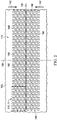
- Figure 1 is a sectional view with a portion shown in elevation, of an example embodiment of a therapy system 100 that can provide negative pressure therapy, instillation of topical treatment solutions, and debridement in accordance with this specification.
- the therapy system 100 may include a dressing and a negative-pressure source.
- a dressing 102 may be fluidly coupled to a negative-pressure source 104, as illustrated in Figure 1.
- Figure 1A is a detail view of a portion of the therapy system 100 of Figure 1 .
- the dressing 102 for example, includes a cover 106, and a tissue interface 107 for positioning adjacent or proximate a tissue site such as, for example, a tissue site 103.
- the tissue interface 107 may be a manifold, for example, a manifold 108.
- the tissue interface 107 may be a tissue removal tool, such as a debridement tool 110 having a tissue-facing surface 111 adapted to face the tissue site 103 and an opposite surface 113 adapted to face, for example, the manifold 108.
- the tissue interface 107 may be both the debridement tool 110 and the manifold 108.
- the therapy system 100 may also include an exudate container, such as a container 112, coupled to the dressing 102 and to the negative-pressure source 104.
- the container 112 may be fluidly coupled to the dressing 102 by a connector 114 and a tube 116, and the container 112 may be fluidly coupled to the negative-pressure source 104 by a tube 118.
- the therapy system 100 may also include an instillation solution source.
- a fluid source 120 may be fluidly coupled to the dressing 102 by a tube 122 and a connector 124, as illustrated in the example embodiment of Figure 1 .
- components of the therapy system 100 may be coupled directly or indirectly.
- the negative-pressure source 104 may be directly coupled to the container 112 and indirectly coupled to the dressing 102 through the container 112.
- Components may be fluidly coupled to each other to provide a path for transferring fluids (i.e., liquid and/or gas) between the components.
- components may be fluidly coupled through a tube, such as the tube 116, the tube 118, and the tube 122.
- a tube is an elongated, cylindrical structure with some flexibility, but the geometry and rigidity may vary.
- components may additionally or alternatively be coupled by virtue of physical proximity, being integral to a single structure, or being formed from the same piece of material. Coupling may also include mechanical, thermal, electrical, or chemical coupling (such as a chemical bond) in some contexts.
- a "connector,” such as the connector 114 and the connector 124, may be used to fluidly couple a tube to a sealed therapeutic environment
- the negative pressure developed by a negative-pressure source may be delivered through a tube to a connector.
- a connector may be a T.R.A.C.® Pad or Sensa T.R.A.C.® Pad available from KCI of San Antonio, Texas.
- the connector 114 may allow the negative pressure generated by the negative-pressure source 104 to be delivered to the sealed therapeutic environment 128.
- a connector may also be a tube inserted through a drape.
- the connector 124 may allow fluid provided by the fluid source 120 to be delivered to the sealed therapeutic environment 128.
- the tissue interface 107 may be placed within, over, on, or otherwise proximate to the tissue site 103.
- the cover 106 may be placed over the tissue interface 107 and sealed to tissue near the tissue site.
- the cover 106 may be sealed to undamaged epidermis peripheral to a tissue site, also known as peritissue.
- the dressing 102 can provide a sealed therapeutic environment 128 proximate to a tissue site, substantially isolated from the external environment, and the negative-pressure source 104 can reduce the pressure in the sealed therapeutic environment 128.
- Negative pressure applied across the tissue site 103 through the tissue interface 107 in the sealed therapeutic environment 128 can induce macrostrain and microstrain in the tissue site 103, as well as remove exudates and other fluids from the tissue site 103, which can be collected in container 112 and disposed of properly.
- the fluid mechanics of using a negative-pressure source to reduce pressure in another component or location, such as within a sealed therapeutic environment can be mathematically complex.
- the basic principles of fluid mechanics applicable to negative-pressure therapy and instillation are generally well-known to those skilled in the art.
- downstream typically refers to a position in a fluid path that is closer to a source of negative pressure or alternatively further away from a source of positive pressure.
- upstream refers to a position in a fluid path further away from a source of negative pressure or closer to a source of positive pressure.
- tissue site such as the tissue site 103, in this context broadly refers to a wound or defect located on or within tissue, including but not limited to, bone tissue, adipose tissue, muscle tissue, neural tissue, dermal tissue, vascular tissue, connective tissue, cartilage, tendons, or ligaments.
- a wound may include chronic, acute, traumatic, subacute, and dehisced wounds, partial-thickness bums, ulcers (such as diabetic, pressure, or venous insufficiency ulcers), flaps, and grafts, for example.
- tissue site may also refer to areas of tissue that are not necessarily wounded or defective, but are instead areas in which it may be desirable to add or promote the growth of additional tissue. For example, negative pressure may be used in certain tissue areas to grow additional tissue that may be harvested and transplanted to another tissue location.
- Negative pressure generally refers to a pressure less than a local ambient pressure, such as the ambient pressure in a local environment external to a sealed therapeutic environment provided by the dressing 102.
- the local ambient pressure may also be the atmospheric pressure at which a tissue site is located.
- the pressure may be less than a hydrostatic pressure associated with tissue at the tissue site.
- values of pressure stated herein are gauge pressures.
- references to increases in negative pressure typically refer to a decrease in absolute pressure, while decreases in negative pressure typically refer to an increase in absolute pressure.
- a negative-pressure soutce such as the negative-pressure source 104, may be a reservoir of air at a negative pressure, or may be a manual or electrically-powered device that can reduce the pressure in a sealed volume, such as a vacuum pump, a suction pump, a wall suction port available at many healthcare facilities, or a micro-pump, for example.
- a negative-pressure source may be housed within or used in conjunction with other components, such as sensors, processing units, alarm indicators, memory, databases, software, display devices, or user interfaces that further facilitate negative-pressure therapy.
- the pressure is generally a low vacuum, also commonly referred to as a rough vacuum, between -5 mmHg (-667 Pa) and -500 mmHg (-66.7 kPa).
- a rough vacuum between -5 mmHg (-667 Pa) and -500 mmHg (-66.7 kPa).
- Common therapeutic ranges are between -75 mmHg (-9.9 kPa) and -300 mmHg (-39.9 kPa).
- the tissue interface 107 can be generally adapted to contact a tissue site.
- the tissue interface 107 may be partially or fully in contact with the tissue site. If the tissue site is a wound, for example, the tissue interface 107 may partially or completely fill the wound, or may be placed over the wound.
- the tissue interface 107 may take many forms, and may have many sizes, shapes, or thicknesses depending on a variety of factors, such as the type of treatment being implemented or the nature and size of a tissue site. For example, the size and shape of the tissue interface 107 may be adapted to the contours of deep and irregular shaped tissue sites. In some embodiments, the tissue interface 107 may be provided in a spiral cut sheet. Moreover, any or all of the surfaces of the tissue interface 107 may have an uneven, coarse, or jagged profile that can induce microstrains and stresses at a tissue site.
- the tissue interface 107 may be a manifold, such as the manifold 108.
- a "manifold" in this context generally includes any substance or structure providing a plurality of pathways adapted to collect or distribute fluid across a tissue site under negative pressure.
- a manifold may be adapted to receive negative pressure from a source and distribute the negative pressure through multiple apertures across a tissue site, which may have the effect of collecting fluid from across a tissue site and drawing the fluid toward the source.
- the fluid path may be reversed or a secondary fluid path may be provided to facilitate delivering fluid across a tissue site.
- the pathways of a manifold may be channels interconnected to improve distribution or collection of fluids across a tissue site.
- cellular foam, open-cell foam, reticulated foam, porous tissue collections, and other porous material such as gauze or felted mat generally include pores, edges, and/or walls adapted to form interconnected fluid pathways.
- Liquids, gels, and other foams may also include or be cured to include apertures and flow channels.
- a manifold may be a porous foam material having interconnected cells or pores adapted to uniformly (or quasi-uniformly) distribute negative pressure to a tissue site.
- the foam material may be either hydrophobic or hydrophilic.
- the pore size of a foam material may vary according to needs of a prescribed therapy.
- the manifold 108 may be a foam having pore sizes in a range of about 400 microns to about 600 microns.
- the tensile strength of the manifold 108 may also vary according to needs of a prescribed therapy. For example, the tensile strength of a foam may be increased for instillation of topical treatment solutions.
- the manifold 108 may be an open-cell, reticulated polyurethane foam such as GranuFoam® dressing available from Kinetic Concepts, Inc. of San Antonio, Texas; in other embodiments the manifold 108 may be an open-cell, reticulated polyurethane foam such as a VeraFlo® foam, also available from Kinetic Concepts, Inc., of San Antonio, Texas.
- the tissue interface 107 may also wick fluid away from a tissue site, while continuing to distribute negative pressure to the tissue site.
- the wicking properties of the tissue interface 107 may draw fluid away from a tissue site by capillary flow or other wicking mechanisms.
- An example of a hydrophilic foam is a polyvinyl alcohol, open-cell foam such as V.A.C. WhiteFoam® dressing available from Kinetic Concepts, Inc. of San Antonio, Texas.
- Other hydrophilic foams may include those made from polyether.
- Other foams that may exhibit hydrophilic characteristics include hydrophobic foams that have been treated or coated to provide hydrophilicity.
- the tissue interface 107 may be constructed from bioresorbable materials. Suitable bioresorbable materials may include, without limitation, a polymeric blend of polylactic acid (PLA) and polyglycolic acid (PGA). The polymeric blend may also include without limitation polycarbonates, polyfumarates, and capralactones.
- the tissue interface 107 may further serve as a scaffold for new cell-growth, or a scaffold material may be used in conjunction with the tissue interface 107 to promote cell-growth.
- a scaffold is generally a substance or structure used to enhance or promote the growth of cells or formation of tissue, such as a three-dimensional porous structure that provides a template for cell growth.
- Illustrative examples of scaffold materials include calcium phosphate, collagen, PLA/PGA, coral hydroxy apatites, carbonates, or processed allograft materials.
- the cover 106 may provide a bacterial barrier and protection from physical trauma.
- the cover 106 may also be a sealing member constructed from a material that can reduce evaporative losses and provide a fluid seal between two components or two environments, such as between a therapeutic environment and a local external environment.
- the cover 106 may be, for example, an elastomeric film or membrane that can provide a seal adequate to maintain a negative pressure at a tissue site for a given negative-pressure source.
- the cover 106 may be a polymer drape, such as a polyurethane film, that is permeable to water vapor but impermeable to liquid. Such drapes typically have a thickness in the range of about 25 microns to about 50 microns. For permeable materials, the permeability generally should be low enough that a desired negative pressure may be maintained.
- An attachment device may be used to attach the cover 106 to an attachment surface, such as undamaged epidermis, a gasket, or another cover.
- the attachment device may take many forms.
- an attachment device may be a medically-acceptable, pressure-sensitive adhesive that extends about a periphery, a portion, or an entire sealing member.
- some or all of the cover 106 may be coated with an acrylic adhesive having a coating weight between about 25 grams per square meter (gsm) to about 65 gsm. Thicker adhesives, or combinations of adhesives, may be applied in some embodiments to improve the seal and reduce leaks.
- Other example embodiments of an attachment device may include a double-sided tape, paste, hydrocolloid, hydrogel, silicone gel, or organogel.
- the container 112 is representative of a container, canister, pouch, or other storage component that can be used to manage exudates and other fluids withdrawn from a tissue site.
- a rigid container may be preferred or required for collecting, storing, and disposing of fluids.
- fluids may be properly disposed of without rigid container storage, and a re-usable container could reduce waste and costs associated with negative-pressure therapy.
- the fluid source 120 may be representative of a container, canister, pouch, bag, or other storage component that can provide a solution for instillation therapy. Compositions of solutions may vary according to prescribed therapy, but examples of solutions that are suitable for some prescriptions include hypochlorite-based solutions, silver nitrate (0.5%), sulfur-based solutions, biguanides, cationic solutions, and isotonic solutions.
- a fluid source such as the fluid source 120, may be a reservoir of fluid at an atmospheric or greater pressure, or may be a manual or electrically-powered device, such as a pump, that can convey fluid to a sealed volume, such as the sealed therapeutic environment 128, for example.
- a fluid source may include a peristaltic pump.
- necrotic tissue may be dead tissue resulting from infection, toxins, or trauma that caused the tissue to die faster than the tissue can be removed by the normal body processes that regulate the removal of dead tissue.
- necrotic tissue may be in the form of slough, which may include a viscous liquid mass of tissue.
- slough is produced by bacterial and fungal infections that stimulate an inflammatory response in the tissue. Slough may be a creamy yellow color and may also be referred to as pus.
- slough such as slough 130, may cover all or a portion of the tissue site 103.
- Necrotic tissue may also include eschar, such as eschar 132.
- Eschar 132 may be a portion of necrotic tissue that has become dehydrated and hardened.
- Eschar 132 may be the result of a burn injury, gangrene, ulcers, fungal infections, spider bites, or anthrax. Eschar may be difficult to move without the use of surgical cutting instruments.
- Necrotic tissue can also include thick exudate and fibrinous slough.
- a tissue site develops necrotic tissue, the tissue site may be treated with a process called debridement.
- Debridement may include the removal of dead, damaged, or infected material, such as thick exudate, fibrinous slough, the slough 130 or the eschar 132, from a tissue site.
- a mechanical process is used to remove necrotic tissue. Mechanical processes may include using scalpels or other cutting tools having a sharp edge to cut away the necrotic tissue from the tissue site.
- mechanical processes of debriding a tissue site may be painful and may require the application of local anesthetics.
- An autolytic process may involve using enzymes and moisture produced by a tissue site to soften and liquefy the necrotic tissue.
- a dressing may be placed over a tissue site having necrotic tissue so that fluid produced by the tissue site may remain in place, hydrating the necrotic tissue.
- Autolytic processes can be pain-free, but autolytic processes are a slow and can take many days. Because autolytic processes are slow, autolytic processes may also involve many dressing changes.
- Some autolytic processes may be paired with negative-pressure therapy so that, as necrotic tissue hydrates, negative pressure supplied to a tissue site may draw off the removed necrotic tissue.
- a manifold positioned at a tissue site to distribute negative-pressure across the tissue site may become blocked or clogged with necrotic tissue broken down by an autolytic process. If a manifold becomes clogged, negative-pressure may not be able to draw off necrotic tissue, which can slow or stop the autolytic process.
- Debridement may also be performed by adding enzymes or other agents to the tissue site.
- the enzymes digest tissue. Often, strict control of the placement of the enzymes and the length of time the enzymes are in contact with a tissue site must be maintained. If enzymes are left on the tissue site for longer than needed, the enzymes may remove too much tissue, contaminate the tissue site, or be carried to other areas of a patient Once carried to other areas of a patient, the enzymes may break down undamaged tissue and cause other complications.
- a negative-pressure source may be fluidly coupled to a tissue site to provide negative pressure to the tissue site for negative-pressure therapy.
- a fluid source may be fluidly coupled to a tissue site to provide therapeutic fluid to the tissue site for instillation therapy.
- the therapy system 100 may include a debridement tool positioned adjacent to a tissue site.
- a debridement tool may be used with negative-pressure therapy and instillation therapy to debride areas of a tissue site having necrotic tissue.
- the therapy system 100 may be used on the tissue site 103 having the slough 130 and the eschar 132.
- the debridement tool 110 may be positioned adjacent to the tissue site 103 so that the debridement tool 110 is in contact with the slough 130 and the eschar 132.
- the manifold 108 may be positioned over the debridement tool 110. In other embodiments, if the tissue site 103 has a depth about a depth of the debridement tool 110, the manifold 108 may not be used.
- the debridement tool 110 may be a substantially flat or substantially planar body.
- the debridement tool 110 may have a thickness 134.
- the thickness 134 may be about 15 mm. In other embodiments, the thickness 134 may be thinner or thicker than about 15 mm as needed for the tissue site 103.
- individual portions of the debridement tool 110 may have a minimal tolerance from the thickness 134. In some embodiments, the thickness 134 may have a tolerance of about 2 mm.
- the debridement tool 110 may be flexible so that the debridement tool 110 can be contoured to a surface of the tissue site 103.
- the debridement tool 110 may be formed from thermoplastic elastomers (TPE), such as styrene ethylene butylene styrene (SEBS) copolymers, or thermoplastic polyurethane (TPU).
- TPE thermoplastic elastomers
- SEBS styrene ethylene butylene styrene
- TPU thermoplastic polyurethane
- the debridement tool 110 may be formed by combining sheets of TPE or TPU.
- the sheets of TPE or TPU may be bonded, welded, adhered, or otherwise coupled to one another.
- the sheets of TPE or TPU may be welded using radiant heat, radio-frequency welding, or laser welding.
- the debridement tool 110 may produce suitable TPE or TPU sheets for the formation of the debridement tool 110.
- sheets of TPE or TPU having a thickness between about 0.2 mm and about 2.0 mm may be used to form a structure having the thickness 134.
- the debridement tool 110 may be formed from a 3D textile, also referred to as a spacer fabric. Suitable 3D textiles may be produced by Heathcoat Fabrics, Ltd., Baltex, and Mueller Textil Group.
- the debridement tool 110 may be formed from a foam.
- cellular foam, open-cell foam, reticulated foam, or porous tissue collections may be used to form the debridement tool 110.
- the debridement tool 110 may be formed of GranuFoam®, grey foam, or Zotefoam.
- Grey foam may be a polyester polyurethane foam having about 60 pores per inch (ppi).
- Zotefoam may be a closed-cell crosslinked polyolefin foam.
- the debridement tool 110 may be an open-cell, reticulated polyurethane foam such as GranuFoam® dressing available from Kinetic Concepts, Inc.
- the debridement tool 110 may be an open-cell, reticulated polyurethane foam such as a V.A.C. VeraFlo® foam, also available from Kinetic Concepts, Inc., of San Antonio, Texas.
- the debridement tool 110 may be formed from a foam that is mechanically or chemically compressed to increase the density of the foam at ambient pressure.
- a foam that is mechanically or chemically compressed may be referred to as a compressed foam.
- a compressed foam may be characterized by a firmness factor (FF) that is defined as a ratio of the density of a foam in a compressed state to the density of the same foam in an uncompressed state.
- firmness factor (FF) of 5 may refer to a compressed foam having a density that is five times greater than a density of the same foam in an uncompressed state.
- Mechanically or chemically compressing a foam may reduce a thickness of the foam at ambient pressure when compared to the same foam that has not been compressed. Reducing a thickness of a foam by mechanical or chemical compression may increase a density of the foam, which may increase the firmness factor (FF) of the foam. Increasing the firmness factor (FF) of a foam may increase a stiffness of the foam in in a direction that is parallel to a thickness of the foam. For example, increasing a firmness factor (FF) of the debridement tool 110 may increase a stiffness of the debridement tool 110 in a direction that is parallel to the thickness 134 of the debridement tool 110.
- a compressed foam may be a compressed GranuFoam®.
- GranuFoam® may have a density of about 0.03 grams per centimeter 3 (g/cm 3 ) in its uncompressed state, If the GranuFoam® is compressed to have a firmness factor (FF) of 5, the GranuFoam® may be compressed until the density of the GranuFoam® is about 0.15g/cm 3 . VeraFlo® foam may also be compressed to form a compressed foam: having a firmness factor (FF) up to 5.
- FF firmness factor
- a compressed foam may also be referred to as a felted foam.
- a felted foam undergoes a thermoforming process to permanently compress the foam to increase the density of the foam.
- a felted foam may also be compared to other felted foams or compressed foams: by comparing the firmness factor of the felted foam to the firmness factor of other compressed or uncompressed foams. Generally a compressed or felted foam may have a firmness factor greater than 1.
- the firmness factor (FF) may also be used to compare compressed foam materials with non-foam materials.
- a Supracor® material may have a firmness factor (FF) that allows Supracor® to be compared to compressed foams.
- the firmness factor (FF) for a non-foam material may represent that the non-foam material has a stiffness that is equivalent to a stiffness a compressed foam having the same firmness factor.
- the debridement tool may have a stiffness that is about the same as the stiffness of a compressed GranuFoam® material having a firmness factor (FF) of 3.
- the compressed foam exhibits less deformation than a similar uncompressed foam.
- the thickness 134 of the debridement tool 110 may deform less than if the debridement tool 110 is formed of a comparable uncompressed foam.
- the decrease in deformation may be caused by the increased stiffness as reflected by the firmness factor (FF).
- FF firmness factor
- the foam material used to form a compressed foam may be either hydrophobic or hydrophilic.
- the pore size of a foam material may vary according to needs of the debridement tool 110 and the amount of compression of the foam. For example, in some embodiments, an uncompressed foam may have pore sizes in a range of about 400 microns to about 600 microns. If the same foam is compressed, the pore sizes may be smaller than when the foam is in its uncompressed state.
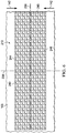
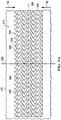
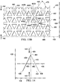
- FIG. 2 is a plan view, illustrating additional details that may be associated with some embodiments of the debridement tool 110.
- the debridement tool 110 may include a plurality of holes 140 or perforations extending through the debridement tool 110 to form walls 148 extending through the debridement tool 110.
- the walls 148 may be parallel to the thickness 134 of the debridement tool 110.
- the walls 148 may be generally perpendicular to the tissue-facing surface 111 and the opposite surface 113 of the debridement tool 110.
- the holes 140 may have a hexagonal shape as shown. In other embodiments, the holes 140 may have a circular, oval, triangular, square, irregular, or amorphous shape.
- the debridement tool 110 may have a first orientation line 136 and a second orientation line 138 that is perpendicular to the first orientation line 136.
- the first orientation line 136 and the second orientation line 138 may be lines of symmetry of the debridement tool 110.
- a line of symmetry may be, for example, an imaginary line across the tissue-facing surface 111 or the opposite surface 113 of the debridement tool 110 defining a fold line such that if the debridement tool 110 is folded on the line of symmetry, the holes 140 and walls 148 would be coincidentally aligned.
- the first orientation line 136 and the second orientation line 138 aid in the description of the debridement tool 110.
- the first orientation line 136 and the second orientation line 138 may be used to refer to the desired directions of contraction of the debridement tool 110.
- the desired direction of contraction may be parallel to the second orientation line 138 and perpendicular to the first orientation line 136.
- the desired direction of contraction may be parallel to the first orientation line 136 and perpendicular to the second orientation line 138.
- the desired direction of contraction may be at a non-perpendicular angle to both the first orientation line 136 and the second orientation line 138.
- the debridement tool 110 may be placed at the tissue site 103 so that the second orientation line 138 extends across the slough 130 and the eschar 132 of Figure 1 .
- the debridement tool 110 is shown as having a generally rectangular shape including longitudinal edges 144 and latitudinal edges 146, the debridement tool 110 may have other shapes.
- the debridement tool 110 may have a diamond, square, or circular shape.
- the shape of the debridement tool 110 may be selected to accommodate the type of tissue site being treated.
- the debridement tool 110 may have an oval or circular shape to accommodate an oval or circular tissue site.
- the first orientation line 136 may be parallel to the longitudinal edges 144.
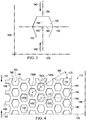
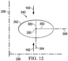
- the hole 140 may include a center 150 and a perimeter 152.
- the hole 140 may have a perforation shape factor (PSF).
- the perforation shape factor (PSF) may represent an orientation of the hole 140 relative to the first orientation line 136 and the second orientation line 138.
- the perforation shape factor (PSF) is a ratio of 1 ⁇ 2 a maximum length of the hole 140 that is parallel to the desired direction of contraction to 1 ⁇ 2 a maximum length of the hole 140 that is perpendicular to the desired direction of contraction.
- the desired direction of contraction is parallel to the second orientation line 138.
- the desired direction of contraction may be indicated by a debriding force 142.
- the hole 140 may have an X-axis 156 extending through the center 150 between opposing vertices of the hexagon and parallel to the first orientation line 136, and a Y-axis 154 extending through the center 150 between opposing sides of the hexagon and parallel to the second orientation line 138.
- the perforation shape factor (PSF) of the hole 140 may be defined as a ratio of a line segment 158 on the Y-axis 154 extending from the center 150 to the perimeter 152 of the hole 140, to a line segment 160 on the X-axis 156 extending from the center 150 to the perimeter 152 of the hole 140.
- the perforation shape factor (PSF) would be 2.69/2.5 or about 1.08.
- the hole 140 may be oriented relative to the first orientation line 136 and the second orientation line 138 so that the perforation shape factor (PSF) may be about 1.07 or 1.1.
- the debridement tool 110 may include the plurality of holes 140 aligned in a pattern of parallel rows.
- the pattern of parallel rows may include a first row 162 of the holes 140, a second row 164 of the holes 140, and a third row 166 of the holes 140.
- the centers 150 of the holes 140 in adjacent rows may be characterized by being offset from the second orientation line 138 along the first orientation line 136.
- a line connecting the centers of adjacent rows may form a strut angle (SA) with the first orientation line 136.
- SA strut angle
- a first hole 140A in the first row 162 may have a center 150A
- a second hole 140B in the second row 164 may have a center 150B.
- a strut line 168 may connect the center 150A with the center 150B.
- the strut line 168 may form an angle 170 with the first orientation line 136.
- the angle 170 may be the strut angle (SA) of the debridement tool 110.
- the strut angle (SA) may be less than about 90°.
- the strut angle (SA) may be between about 30° and about 70° relative to the first orientation line 136.
- the strut angle (SA) may be about 66° from the first orientation line 136.
- a stiffness of the debridement tool 110 in a direction parallel to the first orientation line 136 may increase. Increasing the stiffness of the debridement tool 110 parallel to the first orientation line 136 may increase the compressibility of the debridement tool 110 perpendicular to the first orientation line 136. Consequently, if negative pressure is applied to the debridement tool 110, the debridement tool 110 may be more compliant or compressible in a direction perpendicular to the first orientation line 136. By increasing the compressibility of the debridement tool 110 in a direction perpendicular to the first orientation line 136, the debridement tool 110 may collapse to apply the debriding force 142 to the tissue site 103 described in more detail below.
- the centers 150 of the holes 140 in alternating rows may be spaced from each other parallel to the second orientation line 138 by a length 172.
- the length 172 may be greater than an effective diameter of the hole 140. If the centers 150 of holes 140 in alternating rows are separated by the length 172, walls 148 parallel to the first orientation line 136 may be considered continuous. Generally, the walls 148 may be continuous if the walls 148 do not have any discontinuities or breaks between holes 140.
- the holes 140 in the debridement tool 110 may leave void spaces in the debridement tool 110 and on the tissue-facing surface 111 and the opposite surface 113 of the debridement tool 110 so that only the walls 148 of the debridement tool 110 remain with a surface available to contact the tissue site 103. It may be desirable to minimize the walls 148 so that the holes 140 may collapse, causing the debridement tool 110 to collapse and generate the debriding force 142 in a direction perpendicular to the first orientation line 136. However, it may also be desirable not to minimize the walls 148 so much that the debridement tool 110 becomes too fragile for sustaining the application of a negative pressure.
- the void space percentage (VS) of the holes 140 may be equal to the percentage of the volume or surface area of the void spaces of the tissue-facing surface 111 created by the holes 140 to the total volume or surface area of the tissue-facing surface 111 of the debridement tool 110. In some embodiments, the void space percentage (VS) may be between about 40% and about 60%. In other embodiments, the void space percentage (VS) may be about 55%.
- the holes 140 may be formed during molding of the debridement tool 110. In other embodiments, the holes 140 may be formed by cutting, melting, or vaporizing the debridement tool 110 after the debridement tool 110 is formed. For example, the holes 140 may be formed in the debridement tool 110 by laser cutting the compressed foam of the debridement tool 110. In some embodiments, an effective diameter of the holes 140 may be selected to permit flow of particulates through the holes 140. An effective diameter of a non-circular area is defined as a diameter of a circular area having the same surface area as the non-circular area. In some embodiments, each hole 140 may have an effective diameter of about 3.5 mm.
- each hole 140 may have an effective diameter between about 5 mm and about 20 mm.
- the effective diameter of the holes 140 should be distinguished from the porosity of the material forming the walls 148 of the debridement tool 110.
- an effective diameter of the holes 140 is an order of magnitude larger than the effective diameter of the pores of a material forming the debridement tool 110.
- the effective diameter of the holes 140 may be larger than about 1 mm, while the walls 148 may be formed from GranuFoam® material having a pore size less than about 600 microns.
- the pores of the walls 148 may not create openings that extend all the way through the material.
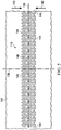
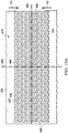
- the holes 140 may form a pattern depending on the geometry of the holes 140 and the alignment of the holes 140 between adjacent and alternating rows in the debridement tool 110 with respect to the first orientation line 136. If the debridement tool 110 is subjected to negative pressure, the holes 140 of the debridement tool 110 may collapse, In some embodiments the void space percentage (VS), the perforation shape factor (PSF), and the strut angle (SA) may cause the debridement tool 110 to contract along the second orientation line 138 perpendicular to the first orientation line 136 as shown in more detail in Figure 5 .
- VS void space percentage
- PSF perforation shape factor
- SA strut angle
- the debridement tool 110 may generate the debriding force 142 along the second orientation line 138, contracting the debridement tool 110, as shown in more detail in Figure 5 .
- the debriding force 142 may be optimized by adjusting the factors described above as set forth in Table 1 below.
- the holes 140 may be hexagonal, have a strut angle (SA) of approximately 66°, a void space percentage (VS) of about 55%, a firmness factor (FF) of about 5, a perforation shape factor (PSF) of about 1.07, and an effective diameter of about 5 mm.
- SA strut angle
- VS void space percentage
- FF firmness factor
- PSF perforation shape factor
- the debriding force 142 asserted by the debridement tool 110 is about 13.3 N. If the effective diameter of the holes 140 of the debridement tool 110 is increased to 10 mm, the debriding force 142 is decreased to about 7.5 N.
- the debridement tool 110 is in the second position, or contracted position, as indicated by the debriding force 142.
- negative pressure is supplied to the sealed therapeutic environment 128 with the negative-pressure source 104.
- the debridement tool 110 contracts from the relaxed position illustrated in Figure 2 to the contracted position illustrated in Figure 5 .
- the thickness 134 of the debridement tool 110 remains substantially the same.
- the debridement tool 110 expands back to the relaxed position.
- the tissue-facing surface 111 of the debridement tool 110 debrides the tissue site 103 by cutting away dead or contaminated tissue from the wound, including the slough 130 and the eschar 132.
- the edges of the holes 140 formed by the tissue-facing surface 111 and transverse surfaces of the walls 148 form cutting edges that debride the tissue site 103, allowing the severed tissue to exit through the holes 140 and the manifold 108 into the container 112 when negative pressure is applied.
- the cutting edges are defined by the perimeter 152 where each hole 140 intersects the tissue-facing surface 111.
- the therapy system 100 may provide cyclic therapy. Cyclic therapy may alternately apply negative pressure to and vent negative pressure from the sealed therapeutic environment 128. In some embodiments, negative pressure may be supplied to the sealed therapeutic environment 128 until the pressure in the sealed therapeutic environment 128 reaches a predetermined therapy pressure. If negative pressure is supplied to the sealed therapeutic environment 128, the debridement tool 110 contracts as shown in Figure 5 . In some embodiments, the sealed therapeutic environment 128 may remain at the therapy pressure for a predetermined therapy period such as, for example, about 10 minutes. In other embodiments, the therapy period may be longer or shorter as needed to supply appropriate negative-pressure therapy to the tissue site 103.
- the sealed therapeutic environment 128 may be vented.
- the negative-pressure source 104 may fluidly couple the sealed therapeutic environment 128 to the atmosphere (not shown), allowing the sealed therapeutic environment 128 to return to ambient pressure.
- the negative-pressure source 104 may vent the sealed therapeutic environment 128 for about 1 minute. In other embodiments, the negative-pressure source 104 may vent the sealed therapeutic environment 128 for longer or shorter periods.
- the debridement tool 110 expands, returning to the relaxed position of Figure 2 . The contraction and expansion of the debridement tool 110 causes the cutting edges of the debridement tool 110 to debride the tissue site 103 as described above. Removed portions of the severed tissue, including the slough 130 and the eschar 132 may be drawn out through the holes 140 when negative pressure is applied to the sealed therapeutic environment 128 by the negative-pressure source 104.
- instillation therapy may be combined with negative-pressure therapy.
- the fluid source 120 may operate to provide fluid to the sealed therapeutic environment 128.
- the fluid source 120 may provide fluid while the negative-pressure source 104 vents the sealed therapeutic environment 128.
- the fluid source 120 may include a pump configured to move instillation fluid from the fluid source 120 to the sealed therapeutic environment 128.
- the negative-pressure source 104 may not vent the sealed therapeutic environment 128. Instead, the negative pressure in the sealed therapeutic environment 128 is used to draw instillation fluid from the fluid source 120 into the sealed therapeutic environment 128.
- the fluid source 120 may provide a volume of fluid to the sealed therapeutic environment 128.
- the volume of fluid may be the same as a volume of the sealed therapeutic environment 128.
- the volume of fluid may be smaller or larger than the sealed therapeutic environment 128 as needed to appropriately apply instillation therapy.
- the fluid provided by the fluid source 120 may remain in the sealed therapeutic environment 128 for a dwell time.
- the dwell time is about 5 minutes.
- the dwell time may be longer or shorter as needed to appropriately administer instillation therapy to the tissue site 103.
- the dwell time may be referred to as a dwell period of a therapy cycle.
- the negative-pressure source 104 may be operated to draw off the instillation fluid into the container 112, completing a cycle of therapy.
- negative pressure may also be supplied to the sealed therapeutic environment 128, starting another cycle of therapy.
- the debridement tool 110 may be contracted and expanded. With each cycle of therapy, the tissue-facing surface 111 of the debridement tool 110 is rubbed across a facing surface of the tissue site 103 by the debriding force 142. The rubbing action of the debridement tool 110 by the debriding force 142 causes the cutting edges of the holes 140 to dislodge portions of the slough 130 and the eschar 132. With each subsequent cycle of therapy, additional portions of slough 130 and eschar 132 are removed from the tissue site 103 by the debriding force 142.
- the dislodged portions of the slough 130 and the eschar 132 in particles may be sufficiently small to be drawn-off from the tissue site 103 by negative-pressure therapy. If instillation therapy is also provided, the fluid from the fluid source 120 may also aid in the removal of debrided tissue. Instillation therapy may also clean the manifold 108, preventing blockage of the manifold 108 by removed slough 130 and eschar 132.
- Figure 6 is a plan view, illustrating additional details that may be associated with some embodiments of a debridement tool 210.
- the debridement tool 210 may be similar to the debridement tool 110 and operate as described above with respect to Figures 1-5 . Similar elements may have similar numbers indexed to 200.
- the debridement tool 210 is shown as having a generally rectangular shape including longitudinal edges 244 and latitudinal edges 246.
- the debridement tool 210 may have a first orientation line 236 and a second orientation line 238 that is perpendicular to the first orientation line 236.
- the first orientation line 236 and the second orientation line 238 may be used to refer to the desired directions of contraction for the debridement tool 210.
- the desired direction of contraction may be parallel to the second orientation line 238 and perpendicular to the first orientation line 236, as shown by the debriding force 142.
- the desired direction of contraction may be perpendicular to the second orientation line 238 and parallel to the first orientation line 236.
- the desired direction of contraction may be at a non-perpendicular to both the second orientation line 238 and the first orientation line 236.
- the debridement tool 210 may be placed at the tissue site 103 so that a tissue-facing surface 211 of the debridement tool 210 may cover portions of the tissue site 103 having slough 130 or eschar 132.
- the debridement tool 210 may include a plurality of holes 240 or perforations extending through the debridement tool 210 to from walls 248 that extend through the debridement tool 210.
- the walls 248 are parallel to the thickness 234 of the debridement tool 210.
- the walls 248 may have transverse surfaces that intersect with the tissue-facing surface 211 to form cutting edges.
- the holes 240 may have a circular shape as shown.
- the hole 240 may include a center 250, a perimeter 252, and a perforation shape factor (PSF).
- PSF perforation shape factor
- the hole 240 may have an X-axis 256 extending through the center 250 parallel to the first orientation line 236, and a Y-axis 254 extending through the center 250 parallel to the second orientation line 238.
- the perforation shape factor (PSF) of the hole 240 may be defined as a ratio of a line segment 258 on the Y-axis 254 extending from the center 250 to the perimeter 252 of the hole 240, to a line segment 260 on the X-axis 256 extending from the center 250 to the perimeter 252 of the hole 240. If a length of the line segment 258 is 2.5 mm and the length of the line segment 260 is 2.5 mm, the perforation shape factor (PSF) would be 2.5/2.5 or about 1.
- the debridement tool 210 may include the plurality of holes 240 aligned in a pattern of parallel rows.
- the pattern of parallel rows may include a first row 262 of the holes 240, a second row 264 of the holes 240, and a third row 266 of the holes 240.
- the X-axis 256 of Figure 7 of each hole 240 may be parallel to the first orientation line 236 of Figure 8 .
- the centers 250 of the holes 240 in adjacent rows, for example, the first row 262 and the second row 264, may be characterized by being offset from the second orientation line 238 along the first orientation line 236.
- a line connecting the centers of adjacent rows may form the strut angle (SA) with the first orientation line 236.
- SA strut angle
- a first hole 240A in the first row 262 may have a center 250A
- a second hole 240B in the second row 264 may have a center 250B.
- a strut line 268 may connect the center 250A with the center 250B.
- the strut line 268 may form an angle 270 with the first orientation line 236.
- the angle 270 may be the strut angle (SA) of the debridement tool 210.
- the strut angle (SA) may be less than about 90°.
- the strut angle (SA) may be between about 30° and about 70° relative to the first orientation line 236.
- the debridement tool 210 may be more compliant or compressible in a direction perpendicular to the first orientation line 236.
- the debridement tool 210 may collapse to apply a debriding force to the tissue site 103 as described in more detail below.
- the centers 250 of the holes 240 in alternating rows may be spaced from each other parallel to the second orientation line 238 by a length 272.
- the length 272 may be greater than an effective diameter of the hole 240. If the centers 250 of holes 240 in alternating rows are separated by the length 272, the walls 248 parallel to the first orientation line 236 may be considered continuous. Generally, the walls 248 may be continuous if the walls 248 do not have any discontinuities or breaks between holes 240.
- the holes 240 in the debridement tool 210 may leave void spaces in the debridement tool 210 and on the tissue-facing surface 211 of the debridement tool 210 so that only walls 248 of the debridement tool 210 remain with a surface available to contact the tissue site 103. It may be desirable to minimize the walls 248 so that the holes 240 collapse, causing the debridement tool 210 to collapse to generate the debriding force 142 in a direction perpendicular to the first orientation line 236. However, it may also be desirable not to minimize the walls 248 so much feat the debridement tool 210 becomes too fragile for sustaining the application of a negative pressure.
- the void space percentage (VS) of the holes 240 may be equal to the percentage of the volume or surface area of the void spaces of the tissue-facing surface 211 created by the holes 240 to the total volume or surface area of the tissue-facing surface 211 of the debridement tool 210. In some embodiments, the void space the void space percentage (VS) may be between about 40% and about 60%. In other embodiments, the void space percentage (VS) may be about 54%.
- a diameter of the holes 240 may be selected to permit flow of particulates through the holes 240, In some embodiment, each hole 240 may have a diameter of about 5 mm. In other embodiments, each hole 240 may have an effective diameter between about 3.5 mm and about 20 mm.
- the holes 240 may form a pattern depending on the geometry of the holes 240 and the alignment of the holes 240 between adjacent and alternating rows in the debridement tool 210 with respect to the first orientation line 236. If the debridement tool 210 is subjected to negative pressure, the holes 240 of the debridement tool 210 may collapse. In some embodiments, the void space percentage (VS), the perforation shape factor (PSF), and the strut angle (SA) may cause the debridement tool 210 to collapse along the second orientation line 238 perpendicular to the first orientation line 236.
- the debriding force 142 may be optimized by adjusting the factors described above as set forth in Table 1 below.
- the holes 240 may be circular, have a strut angle (SA) of approximately 37°, a void space percentage (VS) of about 54%, a firmness factor (FF) of about 5, a perforation shape factor (PSF) of about 1, and a diameter of about 5 mm. If the debridement tool 210 is subjected to a negative pressure of about -125 mmHg, the debridement tool 210 asserts the debriding force 142 of approximately 11.9 N.
- SA strut angle
- VS void space percentage
- FF firmness factor
- PSF perforation shape factor
- the debriding force 142 is decreased to about 6.5 N.
- Figure 9A is a plan view, illustrating additional details that may be associated with some embodiments of a debridement tool 310
- the debridement tool 310 may be similar to the debridement tool 110 and operate as described above with respect to Figures 1-5 . Similar elements may have similar reference numbers indexed to 300.
- the debridement tool 310 may cover the tissue site 103.
- the debridement tool 310 may have a first orientation line 336 and a second orientation line 338 that is perpendicular to the first orientation line 336.
- the first orientation line 336 and the second orientation line 338 may be used to refer to the desired directions of contraction for the debridement tool 310.
- the desired direction of contraction may be parallel to the second orientation line 338 and perpendicular to the first orientation line 336.
- the desired direction of contraction may be perpendicular to the second orientation line 338 and parallel to the first orientation line 336.
- the desired direction of contraction may be at a non-perpendicular angle to both the second orientation line 338 and the first orientation line 336.
- the debridement tool 310 may be placed at the tissue site 103 so that a tissue-facing surface 311 of the debridement tool 310 may cover portions of the tissue site 103 having slough 130 and eschar 132.
- the debridement tool 310 may include a plurality of holes 340 or perforations extending through the debridement tool 310 to form walls 348 that extend through the debridement tool 310.
- the walls 348 are parallel to the thickness 334 of the debridement tool 310.
- the walls 348 may have transverse surfaces that intersect with the tissue-facing surface 311 to form cutting edges.
- the holes 340 may have an ovoid shape as shown.
- the hole 340 may include a center 350, a perimeter 352, and a perforation shape factor (PSF).
- PSF perforation shape factor
- the hole 340 may have an X-axis 356 extending through the center 350 parallel to the first orientation line 336, and a Y-axis 354 extending through the center 350 parallel to the second orientation line 338.
- the perforation shape factor (PSF) of the hole 340 may be defined as a ratio of a line segment 358 on the Y-axis 354 extending from the center 350 to the perimeter 352 of the hole 340, to a line segment 360 on the X-axis 356 extending from the center 350 to the perimeter 352 of the hole 340. If a length of the line segment 358 is 2.5 mm and the length of the line segment 360 is 2.5 mm, the perforation shape factor (PSF) would be 2.5/2.5 or about 1.
- the perforation shape factor (PSF) may change.
- the perforation shape factor (PSF) is now the ratio of a line segment 376 on the Y-axis 354 extending from the center 350 to the perimeter 352 of the hole 340, to a line segment 378 on the X-axis 356 extending from the center 350 to the perimeter 352 of the hole 340. If a length of the line segment 376 is 5 mm and the length of the line segment 378 is 2.5 mm, the perforation shape factor (PSF) would be 5/2.5 or about 2.
- the perforation shape factor (PSF) may change.
- the perforation shape factor (PSF) is now the ratio of a line segment 380 on the Y-axis 354 extending from the center 350 to the perimeter 352 of the hole 340, to a line segment 382 on the X-axis 356 extending from the center 350 to the perimeter 352 of the hole 340. If a length of the line segment 380 is 2.5 mm and the length of the line segment 382 is 5 mm, the perforation shape factor (PSF) would be 2.5/5 or about 1/2.
- the debridement tool 310 may include the plurality of holes 340 aligned in a pattern of parallel rows.
- the pattern of parallel rows may include a first row 362 of the holes 340, a second row 364 of the holes 340, and a third row 366 of the holes 340.
- the X-axis 356 of each hole 340 of Figures 10, 11 , and 12 may be parallel to the first orientation line 336 of Figure 9B .
- the centers 350 of the holes 340 in adjacent rows, for example, the first row 362 and the second row 364, may be characterized by being offset from the second orientation line 338 along the first orientation line 336.
- a line connecting the centers of adjacent rows may form a strut angle (SA) with the first orientation line 336.
- SA strut angle
- a first hole 340A in the first row 362 may have a center 350A
- a second hole 340B in the second row 364 may have a center 350B.
- a strut line 368 may connect the center 350A with the center 350B.
- the strut line 368 may form an angle 370 with the first orientation line 336.
- the angle 370 may be the strut angle (SA) of the debridement tool 310.
- the strut angle (SA) may be less than about 90°.
- the strut angle (SA) may be between about 30° and about 70° relative to the first orientation line 336.
- the debridement tool 310 may be more compliant or compressible in a direction perpendicular to the first orientation line 336.
- the debridement tool 310 may collapse to apply the debriding force 142 to the tissue site 103 as described in more detail below.
- the centers 350 of the holes 340 in alternating rows may be spaced from each other parallel to the second orientation line 338 by a length 372.
- the length 372 may be greater than an effective diameter of the hole 340. If the centers 350 of holes 340 in alternating rows are separated by the length 372, the walls 348 parallel to the first orientation line 336 may be considered continuous. Generally, the walls 348 may be continuous if the walls 348 do not have any discontinuities or breaks between holes 340.
- the holes 340 in the debridement tool 310 may leave void spaces in the debridement tool 310 and on the tissue-facing surface 311 of the debridement tool 310 so that only walls 348 of the debridement tool 310 remain with a surface available to contact the tissue site 103. It may be desirable to minimize the walls 348 so that the holes 340 may collapse, causing the debridement tool 310 to collapse the debriding force 142 in a direction perpendicular to the first orientation line 336. However, it may also be desirable not to minimize the walls 348 so much that the debridement tool 310 becomes too fragile for sustaining the application of a negative pressure.
- the void space percentage (VS) of the holes 340 may be equal to the percentage of the volume or surface area of the void spaces of the tissue-facing surface 311 created by the holes 340 to the total volume or surface area of the tissue-facing surface 311 of the debridement tool 310. In some embodiments, the void space percentage (VS) may be between about 40% and about 60%. In other embodiments, the void space percentage (VS) may be about 56%.
- an effective diameter of the holes 340 may be selected to permit flow of particulates through the holes 340.
- each hole 340 may have an effective diameter of about 7 mm. In other embodiments, each hole 340 may have an effective diameter between about 2.5 mm and about 20 mm.
- the holes 340 may form a pattern depending on the geometry of the holes 340 and the alignment of the holes 340 between adjacent and alternating rows in the debridement tool 310 with respect to the first orientation line 336. If the debridement tool 310 is subjected to negative pressure, the holes 340 of the debridement tool 310 may collapse, causing the debridement tool 310 to collapse along the second orientation line 338 perpendicular to the first orientation line 336.
- the debridement tool 310 may generate the debriding force 142 along the second orientation line 338 such that the debridement tool 310 is contracted in the same direction to debride the tissue site 103.
- the debriding force 142 may be optimized by adjusting the factors described above as set forth in Table 1 below.
- the holes 340 may be ovular, have a strut angle (SA) of approximately 47°, a void space percentage (VS) of about 56%, a firmness factor (FF) of about 5, a perforation shape factor (PSF) of about 1, and an effective diameter of about 7 mm (where the major axis is about 10 mm and the minor axis is about 5 mm). If the debridement tool 310 is subjected to a negative pressure of about -125 mmHg, the debridement tool 310 asserts the debriding force 142 of approximately 13.5 N.
- SA strut angle
- VS void space percentage
- FF firmness factor
- PSF perforation shape factor
- Figure 13A is a plan view, illustrating additional details that may be associated with some embodiments of a debridement tool 410.
- the debridement tool 410 may be similar to the debridement tool 110 and operate as described with respect to Figures 1-5 . Similar elements may have similar reference numbers indexed to 400.
- the debridement tool 410 is shown as having a generally rectangular shape including longitudinal edges 444 and latitudinal edges 446.
- the debridement tool 410 may cover the tissue site 103.
- the debridement tool 410 may have a first orientation line 436 and a second orientation line 438 that is perpendicular to the first orientation line 436.
- the first orientation line 436 and the second orientation line 438 may be used to refer to the desired directions of contraction for the debridement tool 410.
- the desired direction of contraction may be parallel to the second orientation line 438 and perpendicular to the first orientation line 436.
- the desired direction of contraction may be perpendicular to the second orientation line 438 and parallel to the first orientation line 436.
- the desired direction of contraction may be at a non-perpendicular angle to both the second orientation line 438 and the first orientation line 436.
- the debridement tool 410 may be placed at the tissue site 103 so that a tissue-facing surface 411 of the debridement tool 410 may cover portions of the tissue site 103 having slough 130 or eschar 132.
- the debridement tool 410 may include a plurality of holes 440 or perforations extending through the debridement tool 410 to form walls 448 that extend through the debridement tool 410.
- the walls 448 are parallel to the thickness 434 of the debridement tool 410.
- the walls 448 may have transverse surfaces that intersect with the tissue-facing surface 411 to form cutting edges.
- the holes 440 may have a triangular shape as shown.
- the hole 440 may include a center 450, a perimeter 452, and a perforation shape factor (PSF).
- the hole 440 may include a first vertex 484, a second vertex 486, and a third vertex 488.
- the hole 440 may have an X-axis 456 extending through the center 450 parallel to the first orientation line 436, and a Y-axis 454 extending through the center 450 parallel to the second orientation line 438.
- the perforation shape factor (PSF) of the hole 440 may be defined as a ratio of a line segment 458 on the Y-axis 454 extending from the center 450 to the perimeter 452 of the hole 440, to a line segment 460 on the X-axis 456 extending from the center 450 to the perimeter 452 of the hole 440. If a length of the line segment 458 is 1.1 mm and the length of the line segment 460 is 1 mm, the perforation shape factor (PSF) would be 1.1/1 or about 1.1.
- the debridement tool 410 may include the plurality of holes 440 aligned in a pattern of parallel rows.
- the pattern of parallel rows may include a first row 462 of the holes 440, a second row 464 of the holes 440, and a third row 466 of the holes 440.
- the X-axis 456 of Figure 14 of each hole 440 may be parallel to the first orientation line 436 of Figure 13B .
- a first hole 440A in the first row 462 may be oriented so that the first vertex 484A may be between the first orientation line 436 and a leg of the first hole 440A opposite the first vertex 484A.
- a hole 440C that is adjacent the first hole 440A in the first row 462 may be oriented so that the first vertex 484C may be oriented opposite the first hole 440A.
- the centers 450 of the holes 440 in adjacent rows having the first vertex 484 oriented in a same direction, for example, the first row 462 and the second row 464, may be characterized by being offset from the second orientation line 438 along the first orientation line 436.
- a line connecting the centers 450 of adjacent rows may form a strut angle (SA) with the first orientation line 436.
- SA strut angle
- a first hole 440A in the first row 462 may have a center 450A
- a second hole 440B in the second row 464 may have a center 450B and a first vertex 484B.
- a strut line 468 may connect the center 450A with the center 450B.
- the strut line 468 may form an angle 470 with the first orientation line 436.
- the angle 470 may be the strut angle (SA) of the debridement tool 410.
- the strut angle (SA) may be less than about 90°.
- the strut angle (SA) may be between about 40° and about 70° relative to the first orientation line 436.
- the debridement tool 410 may be more compliant or compressible in a direction perpendicular to the first orientation line 436. By increasing the compressibility of the debridement tool 410 in a direction perpendicular to the first orientation line 436, the debridement tool 410 may collapse to apply the debriding force 142 to the tissue site 103 as described in more detail below.
- the holes 440 in the debridement tool 410 may leave void spaces in the debridement tool 410 and on the tissue-facing surface 411 of the debridement tool 410 so that only the walls 448 of the debridement tool 410 remain with a surface available to contact the tissue site 103. It may be desirable to minimize the walls 448 so that the holes 440 may collapse, causing the debridement tool 410 to generate the debriding force 142 in a direction perpendicular to the first orientation line 436. However, it may also be desirable not to minimize the walls 448 so much that the debridement tool 410 becomes too fragile for sustaining the application of a negative pressure.
- the void space percentage (VS) of the holes 440 may be equal to the percentage of the volume or surface area of the void spaces of the tissue-facing surface 411 created by the holes 440 to the total volume or surface area of the tissue-facing surface 411 of the debridement tool 410. In some embodiments, the void space percentage (VS) may be between about 40% and about 60%. In other embodiments, the void space percentage (VS) may be about 56%.
- an effective diameter of the holes 440 may be selected to permit flow of particulates through the holes 440.
- each hole 440 may have an effective diameter of about 7 mm. In other embodiments, each hole 440 may have an effective diameter between about 2.5 mm and about 20 mm.
- the holes 440 may form a pattern depending on the geometry of the holes 440 and the alignment of the holes 440 between adjacent and alternating rows in the debridement tool 410 with respect to the first orientation line 436. If the debridement tool 410 is subjected to negative pressure, the holes 440 of the debridement tool 410 may collapse. In some embodiments, the void space percentage (VS), the perforation shape factor (PSF), and the strut angle (SA) may cause the debridement tool 410 to collapse along the second orientation line 438 perpendicular to the first orientation line 436.
- VS void space percentage
- PSF perforation shape factor
- SA strut angle
- the debridement tool 410 may generate the debriding force 142 along the second orientation line 438 such that the debridement tool 410 is contracted in the same direction.
- the debriding force 142 may be optimized by adjusting the factors described above as set forth in Table 1 below.
- the holes 440 may be triangular, have a strut angle (SA) of approximately 63°, a void space percentage (VS) of about 40%, a firmness factor (FF) of 5, a perforation shape factor (PSF) of 1.1, and an effective diameter of about 10 mm. If the debridement tool 410 is subjected to a negative pressure of about -125 mmHg, the debridement tool 410 may assert the debriding force 142 of approximately 13.5 N.
- FIG 15 is a plan view, illustrating additional details that may be associated with some embodiments of a debridement tool 510.
- the debridement tool 510 may be similar to the debridement tool 110 described above with respect to Figures 1-5 .
- the debridement tool 510 may include stripes 516 and stripes 518.
- the debridement tool 510 may be formed from a foam, similar to GranuFoam®.
- the stripes 518 may be formed by compressing portions of the foam so that the stripes 516 have a first density and the stripes 518 have a second density.
- the second density is greater than the first density, for example.
- the second density may be between about 3 times and about 5 times greater than the first density.
- the stripes 516 may be an uncompressed foam, and the stripes 518 may be a compressed foam having a firmness factor of about 5. Generally, the stripes 516 may be more compressible than the stripes 518. In some embodiments, the stripes 516 and the stripes 518 may be vertically oriented relative to a tissue site, and in other embodiments, the stripes 516 and the stripes 518 may be horizontally oriented relative to a tissue site. In still other embodiments, the stripes 516 and the stripes 518 may be oriented at an angle relative to a tissue site.
- the foam material of the debridement tool 510 may have cutting edges formed by pores in the foam material that are positioned on a tissue-facing surface 511 of the debridement tool 510.
- the stripes 516 may collapse before the stripes 518. In some embodiments, if the stripes 516 collapse, the debridement tool 510 contracts perpendicular to the stripes 516. If the debridement tool 510 is cycled between contracted and relaxed states, as described above, the cutting edges of the pores may debride tissue similar to the cutting edges of the debridement tool 110, described above.
- a debriding force, such as the debriding force 142, generated by a debridement tool, such as the debridement tool 110, may be related to a compressive force generated by applying negative pressure at a therapy pressure to a sealed therapeutic environment.
- the debriding force 142 may be proportional to a product of a therapy pressure (TP) in the sealed therapeutic environment 128, the compressibility factor (CF) of the debridement tool 110, and a surface area (A) the tissue-facing surface 111 of the debridement tool 110.
- TP therapy pressure
- CF compressibility factor
- A surface area
- the therapy pressure TP is measured in N/m 2
- the compressibility factor (CF) is dimensionless
- the area (A) is measured in m 2
- the debriding force is measured in Newtons (N).
- the compressibility factor (CF) resulting from the application of negative pressure to a debridement tool may be, for example, a dimensionless number that is proportional to the product of the void space percentage (VS) of a debridement tool, the firmness factor (FF) of the debridement tool, the strut angle (SA) of the holes in the debridement tool, and the perforation shape factor (PSF) of the holes in the debridement tool.
- the relationship is expressed as follows: Compressibility Factor CF ⁇ VS ⁇ FF ⁇ sin SA ⁇ PSF
- debridement tools formed from different materials with holes of different shapes were manufactured and tested to determine the debriding force of the debridement tools.
- the therapy pressure TP was about -125 mmHg and the dimensions of the debridement tool were about 200 mm by about 53 mm so that the surface area (A) of the tissue-facing surface of the debridement tool was about 106 cm 2 or 0.0106 m 2 .
- the debriding force for a Supracor® debridement tool 110 having a firmness factor (FF) of 3 was about 13.3 where the Supracor® debridement tool 110 had hexagonal holes 140 with a distance between opposite vertices of 5 mm, a perforation shape factor (PSF) of 1.07, a strut angle (SA) of approximately 66°, and a void space percentage (VS) of about 55%.
- a similarly dimensioned GranuFoam® debridement tool 110 generated the debriding force 142 of about 9.1 Newtons (N). TABLE 1 Material VS FF SA Hole Shape PSF Major diam.
- the formulas described above may not precisely describe the debriding forces due to losses in force due to the transfer of the force from the debridement tool to the wound.
- the modulus and stretching of the cover 106, the modulus of the tissue site 103, slippage of the cover 106 over the tissue site 103, and friction between the debridement tool 110 and the tissue site 103 may cause the actual value of the debriding force 142 to be less than the calculated value of the debriding force 142.
- the systems, apparatuses, and exemplary methods described herein may provide significant advantages. For example, Combining the mechanical rubbing action of a debridement tool with the hydrating and flushing action of instillation and negative-pressure therapy may enable low or no pain debridement of a tissue site.
- a debridement tool as described herein may also require less monitoring from a clinician or other attendant as compared to other mechanical debridement processes and enzymatic debridement processes.
- debridement tools as described herein may not become blocked by removed necrotic tissue as may occur during autolytic debridement of a tissue site.
Landscapes
- Chemical & Material Sciences (AREA)
- Organic Chemistry (AREA)
- Health & Medical Sciences (AREA)
- Life Sciences & Earth Sciences (AREA)
- Heart & Thoracic Surgery (AREA)
- General Health & Medical Sciences (AREA)
- Veterinary Medicine (AREA)
- Public Health (AREA)
- Animal Behavior & Ethology (AREA)
- Biomedical Technology (AREA)
- Engineering & Computer Science (AREA)
- Surgery (AREA)
- Vascular Medicine (AREA)
- Nuclear Medicine, Radiotherapy & Molecular Imaging (AREA)
- Molecular Biology (AREA)
- Medical Informatics (AREA)
- Anesthesiology (AREA)
- Hematology (AREA)
- Epidemiology (AREA)
- Chemical Kinetics & Catalysis (AREA)
- Virology (AREA)
- Dispersion Chemistry (AREA)
- AIDS & HIV (AREA)
- Communicable Diseases (AREA)
- Oncology (AREA)
- General Chemical & Material Sciences (AREA)
- Medicinal Chemistry (AREA)
- Tropical Medicine & Parasitology (AREA)
- Pharmacology & Pharmacy (AREA)
- Media Introduction/Drainage Providing Device (AREA)
- Surgical Instruments (AREA)
Claims (13)
- System zum Behandeln einer Gewebestelle (103), umfassend:einen Verteiler (108), angepasst zum Abgeben eines negativen Drucks an die Gewebestelle und aufweisend einen ersten Festigkeitsfaktor, wobei der Verteiler (108) ein Schaum ist;eine Abdeckung (106), angepasst zum Bilden eines abgedichteten Raums über dem Verteiler und der Gewebestelle zum Aufnehmen eines negativen Drucks aus einer Quelle für negativen Druck (104); undein Gewebezwischenstück (110), angepasst, um zwischen dem Verteiler und der Gewebestelle positioniert zu sein, wobei das Gewebezwischenstück einen zweiten Festigkeitsfaktor, der größer als der erste Festigkeitsfaktor ist, und eine Vielzahl von Löchern (140), die durch Wände (148) voneinander getrennt sind, aufweist, wobei das Gewebezwischenstück (110) ein Schaum ist; undwobei ein Festigkeitsfaktor ein Verhältnis der Dichte eines Schaums in einem verdichteten Zustand zu der Dichte des gleichen Schaums in einem unverdichteten Zustand ist.
- System nach Anspruch 1, wobei jedes der Vielzahl von Löchern einen Perforationsformfaktor und einen Druckstrebenwinkel aufweist, die die Vielzahl von Löchern in einem Muster auf dem Gewebezwischenstück anordnen.
- System nach Anspruch 2, wobei der Druckstrebenwinkel etwa 90 Grad beträgt.
- System nach Anspruch 2, wobei der Druckstrebenwinkel weniger als etwa 90 Grad beträgt.
- System nach Anspruch 2, wobei der Perforationsformfaktor jedes der Vielzahl von Löchern weniger als etwa 1 beträgt.
- System nach Anspruch 1, weiter umfassend eine Fluidquelle (120), angepasst, um fluidisch mit dem abgedichteten Raum gekoppelt zu sein, um Fluid an den abgedichteten Raum bereitzustellen.
- System nach Anspruch 1, wobei jedes der Vielzahl von Löchern einen mittleren effektiven Durchmesser von etwa 5 mm aufweist.
- System nach Anspruch 1, wobei jedes der Vielzahl von Löchern in zwei oder mehr parallelen Reihen ausgebildet ist.
- System nach Anspruch 1, wobei eine Dicke des Gewebezwischenstücks etwa 15 mm beträgt.
- System nach Anspruch 1, wobei der zweite Festigkeitsfaktor etwa 5 beträgt.
- System nach Anspruch 1, wobei der zweite Festigkeitsfaktor etwa 3 beträgt.
- System nach Anspruch 1, wobei eine Form jedes der Vielzahl von Löchern hexagonal, elliptisch, kreisförmig oder dreieckig ist.
- System nach Anspruch 1, wobei das Gewebezwischenstück ein verdichteter Schaum oder ein verfilzter Schaum ist.
Priority Applications (1)
| Application Number | Priority Date | Filing Date | Title |
|---|---|---|---|
| EP20212298.2A EP3821858A1 (de) | 2014-05-09 | 2015-05-08 | Ablösungsverband zur verwendung mit unterdruck- und fluidinstillation |
Applications Claiming Priority (4)
| Application Number | Priority Date | Filing Date | Title |
|---|---|---|---|
| US201461991134P | 2014-05-09 | 2014-05-09 | |
| EP17186252.7A EP3263078B1 (de) | 2014-05-09 | 2015-05-08 | Ablösungsverband zur verwendung mit unterdruck- und fluidinstillation |
| EP15724880.8A EP3139879B1 (de) | 2014-05-09 | 2015-05-08 | Ablösungsverband zur verwendung mit unterdruck- und fluidinstillation |
| PCT/US2015/030023 WO2015172104A1 (en) | 2014-05-09 | 2015-05-08 | Debriding dressing for use with negative pressure and fluid instillation |
Related Parent Applications (3)
| Application Number | Title | Priority Date | Filing Date |
|---|---|---|---|
| EP15724880.8A Division EP3139879B1 (de) | 2014-05-09 | 2015-05-08 | Ablösungsverband zur verwendung mit unterdruck- und fluidinstillation |
| EP17186252.7A Division EP3263078B1 (de) | 2014-05-09 | 2015-05-08 | Ablösungsverband zur verwendung mit unterdruck- und fluidinstillation |
| EP17186252.7A Division-Into EP3263078B1 (de) | 2014-05-09 | 2015-05-08 | Ablösungsverband zur verwendung mit unterdruck- und fluidinstillation |
Related Child Applications (1)
| Application Number | Title | Priority Date | Filing Date |
|---|---|---|---|
| EP20212298.2A Division EP3821858A1 (de) | 2014-05-09 | 2015-05-08 | Ablösungsverband zur verwendung mit unterdruck- und fluidinstillation |
Publications (2)
| Publication Number | Publication Date |
|---|---|
| EP3527180A1 EP3527180A1 (de) | 2019-08-21 |
| EP3527180B1 true EP3527180B1 (de) | 2021-01-06 |
Family
ID=53267627
Family Applications (4)
| Application Number | Title | Priority Date | Filing Date |
|---|---|---|---|
| EP20212298.2A Pending EP3821858A1 (de) | 2014-05-09 | 2015-05-08 | Ablösungsverband zur verwendung mit unterdruck- und fluidinstillation |
| EP17186252.7A Active EP3263078B1 (de) | 2014-05-09 | 2015-05-08 | Ablösungsverband zur verwendung mit unterdruck- und fluidinstillation |
| EP19164841.9A Active EP3527180B1 (de) | 2014-05-09 | 2015-05-08 | Ablösungsverband zur verwendung mit unterdruck- und fluidinstillation |
| EP15724880.8A Active EP3139879B1 (de) | 2014-05-09 | 2015-05-08 | Ablösungsverband zur verwendung mit unterdruck- und fluidinstillation |
Family Applications Before (2)
| Application Number | Title | Priority Date | Filing Date |
|---|---|---|---|
| EP20212298.2A Pending EP3821858A1 (de) | 2014-05-09 | 2015-05-08 | Ablösungsverband zur verwendung mit unterdruck- und fluidinstillation |
| EP17186252.7A Active EP3263078B1 (de) | 2014-05-09 | 2015-05-08 | Ablösungsverband zur verwendung mit unterdruck- und fluidinstillation |
Family Applications After (1)
| Application Number | Title | Priority Date | Filing Date |
|---|---|---|---|
| EP15724880.8A Active EP3139879B1 (de) | 2014-05-09 | 2015-05-08 | Ablösungsverband zur verwendung mit unterdruck- und fluidinstillation |
Country Status (7)
| Country | Link |
|---|---|
| US (3) | US10143485B2 (de) |
| EP (4) | EP3821858A1 (de) |
| JP (2) | JP6728062B2 (de) |
| CN (3) | CN106456848B (de) |
| AU (3) | AU2015255719B2 (de) |
| CA (1) | CA2947298C (de) |
| WO (1) | WO2015172104A1 (de) |
Families Citing this family (72)
| Publication number | Priority date | Publication date | Assignee | Title |
|---|---|---|---|---|
| US9421132B2 (en) | 2011-02-04 | 2016-08-23 | University Of Massachusetts | Negative pressure wound closure device |
| CA3101119C (en) | 2011-06-24 | 2023-07-04 | Kci Licensing, Inc. | Reduced-pressure dressings employing tissue-fixation elements |
| CA2874581C (en) | 2012-05-24 | 2022-06-07 | Smith & Nephew Inc. | Devices and methods for treating and closing wounds with negative pressure |
| US10130520B2 (en) | 2012-07-16 | 2018-11-20 | Smith & Nephew, Inc. | Negative pressure wound closure device |
| WO2014165275A1 (en) | 2013-03-13 | 2014-10-09 | Smith & Nephew Inc. | Negative pressure wound closure device and systems and methods of use in treating wounds with negative pressure |
| US10898217B2 (en) | 2014-05-09 | 2021-01-26 | Kci Licensing, Inc. | Dressing providing apertures with multiple orifice sizes for negative-pressure therapy |
| JP6640114B2 (ja) * | 2014-05-09 | 2020-02-05 | ケーシーアイ ライセンシング インコーポレイテッド | 陰圧および流体点滴注入と共に使用するための破壊的ドレッシング |
| DK3288508T3 (da) | 2015-04-27 | 2020-03-09 | Smith & Nephew | Anordninger med reduceret tryk |
| EP4209201A1 (de) | 2015-04-29 | 2023-07-12 | Smith & Nephew, Inc. | Unterdruckwundverschlussvorrichtung |
| US11471586B2 (en) | 2015-12-15 | 2022-10-18 | University Of Massachusetts | Negative pressure wound closure devices and methods |
| WO2017153357A1 (en) | 2016-03-07 | 2017-09-14 | Smith & Nephew Plc | Wound treatment apparatuses and methods with negative pressure source integrated into wound dressing |
| WO2017160412A1 (en) * | 2016-03-17 | 2017-09-21 | Kci Licensing, Inc. | Systems and methods for treating a tissue site using one manifold and multiple therapy units |
| SG11201809178XA (en) | 2016-04-26 | 2018-11-29 | Smith & Nephew | Wound dressings and methods of use with integrated negative pressure source having a fluid ingress inhibition component |
| AU2017259003B2 (en) | 2016-05-03 | 2022-09-22 | Smith & Nephew Plc | Systems and methods for driving negative pressure sources in negative pressure therapy systems |
| CA3038206A1 (en) | 2016-05-03 | 2017-11-09 | Smith & Nephew Plc | Optimizing power transfer to negative pressure sources in negative pressure therapy systems |
| US11096831B2 (en) | 2016-05-03 | 2021-08-24 | Smith & Nephew Plc | Negative pressure wound therapy device activation and control |
| CN109561994B (zh) | 2016-08-25 | 2022-03-15 | 史密夫及内修公开有限公司 | 吸收性负压伤口疗法敷料 |
| WO2018060144A1 (en) | 2016-09-27 | 2018-04-05 | Smith & Nephew Plc | Wound closure devices with dissolvable portions |
| JP7055795B2 (ja) | 2016-09-30 | 2022-04-18 | スミス アンド ネフュー ピーエルシー | 一体化された電子機器を備えた陰圧創傷治療装置及び方法 |
| US11617684B2 (en) | 2016-11-02 | 2023-04-04 | Smith & Nephew, Inc. | Wound closure devices |
| JP7361606B2 (ja) | 2017-03-08 | 2023-10-16 | スミス アンド ネフュー ピーエルシー | 障害状態の存在下での陰圧創傷療法装置の制御 |
| WO2018206420A1 (en) | 2017-05-09 | 2018-11-15 | Smith & Nephew Plc | Redundant controls for negative pressure wound therapy systems |
| WO2018226687A1 (en) | 2017-06-07 | 2018-12-13 | Kci Licensing, Inc. | Methods for manufacturing and assembling dual material tissue interface for negative-pressure therapy |
| CA3061327A1 (en) | 2017-06-07 | 2018-12-13 | Kci Licensing, Inc. | Peel and place dressing for negative-pressure therapy |
| EP3634330A1 (de) | 2017-06-07 | 2020-04-15 | KCI Licensing, Inc. | Zusammengesetzte wundauflagen für verbesserte granulationsreduzierte mazeration mit unterdruckbehandlung |
| US11471332B2 (en) | 2017-06-07 | 2022-10-18 | Kci Licensing, Inc. | Systems, apparatuses, and methods for negative-pressure treatment with reduced tissue in-growth |
| CA3065521A1 (en) | 2017-06-07 | 2018-12-13 | Kci Licensing, Inc. | Multi-layer wound filler for extended wear time |
| WO2018226627A1 (en) | 2017-06-07 | 2018-12-13 | Kci Licensing, Inc. | Composite dressings for improved granulation and reduced maceration with negative-pressure treatment |
| US11207217B2 (en) | 2017-06-07 | 2021-12-28 | Kci Licensing, Inc. | Methods for manufacturing and assembling dual material tissue interface for negative-pressure therapy |
| CN110997029A (zh) | 2017-06-07 | 2020-04-10 | 凯希特许有限公司 | 用于通过负压治疗来改善肉芽生长和减少泡软的复合敷料 |
| US11351063B2 (en) | 2017-06-07 | 2022-06-07 | Kci Licensing, Inc. | Composite dressings for improved granulation and reduced maceration with negative-pressure treatment |
| EP3638169A1 (de) | 2017-06-13 | 2020-04-22 | Smith & Nephew PLC | Zusammenklappbare struktur und anwendungsverfahren |
| US11872110B2 (en) | 2017-06-13 | 2024-01-16 | Smith & Nephew Plc | Wound closure device and method of use |
| US11395873B2 (en) | 2017-06-14 | 2022-07-26 | Smith & Nephew, Inc. | Control of wound closure and fluid removal management in wound therapy |
| EP3638170B1 (de) | 2017-06-14 | 2024-03-13 | Smith & Nephew PLC | Zusammenklappbare struktur für wundverschluss und verwendungsverfahren |
| CN110740715B (zh) | 2017-06-14 | 2022-04-12 | 史密夫及内修公开有限公司 | 用于伤口闭合的可塌缩片材及使用方法 |
| JP2020523052A (ja) | 2017-06-14 | 2020-08-06 | スミス アンド ネフュー インコーポレイテッド | 創傷治療における創傷閉鎖の流体除去管理および制御 |
| EP3658090B1 (de) | 2017-07-27 | 2021-11-10 | Smith & Nephew PLC | Anpassbare wundverschlussvorrichtung |
| US11590030B2 (en) | 2017-08-07 | 2023-02-28 | Smith & Nephew Plc | Wound closure device with protective layer and method of use |
| EP3675925A1 (de) | 2017-08-29 | 2020-07-08 | Smith & Nephew PLC | System und verfahren zur überwachung des wundverschlusses |
| GB201718070D0 (en) | 2017-11-01 | 2017-12-13 | Smith & Nephew | Negative pressure wound treatment apparatuses and methods with integrated electronics |
| AU2018331954A1 (en) | 2017-09-13 | 2020-03-19 | Smith & Nephew Plc | Negative pressure wound treatment apparatuses and methods with integrated electronics |
| RU2020113361A (ru) * | 2017-09-20 | 2021-10-20 | Колопласт А/С | Приспособление для ухода за раной для удаления омертвевших тканей ран |
| US11432967B2 (en) * | 2017-10-23 | 2022-09-06 | Kci Licensing, Inc. | Fluid bridge for simultaneous application of negative pressure to multiple tissue sites |
| AU2018354152B2 (en) | 2017-10-23 | 2024-02-29 | Solventum Intellectual Properties Company | Low profile distribution components for wound therapy |
| CN111447901A (zh) * | 2017-10-24 | 2020-07-24 | 凯希特许有限公司 | 清创伤口敷料和使用清创伤口敷料的系统 |
| GB201718072D0 (en) | 2017-11-01 | 2017-12-13 | Smith & Nephew | Negative pressure wound treatment apparatuses and methods with integrated electronics |
| GB201718054D0 (en) | 2017-11-01 | 2017-12-13 | Smith & Nephew | Sterilization of integrated negative pressure wound treatment apparatuses and sterilization methods |
| WO2019086332A1 (en) | 2017-11-01 | 2019-05-09 | Smith & Nephew Plc | Negative pressure wound treatment apparatuses and methods with integrated electronics |
| US20210077302A1 (en) * | 2018-01-04 | 2021-03-18 | Kci Licensing, Inc. | Peel And Place Dressing For Thick Exudate And Instillation |
| WO2019157466A1 (en) | 2018-02-12 | 2019-08-15 | Healyx Labs, Inc. | Negative pressure wound therapy systems, devices, and methods |
| EP3755290B1 (de) * | 2018-02-23 | 2023-06-21 | 3M Innovative Properties Company | Verband mit polster für lineare gewebestellen |
| US11040127B2 (en) | 2018-04-09 | 2021-06-22 | Kci Licensing, Inc. | Abdominal dressing with mechanism for fascial closure |
| USD878609S1 (en) | 2018-04-09 | 2020-03-17 | Kci Licensing, Inc. | Compressive layer for abdominal wound dressing |
| WO2019226900A1 (en) * | 2018-05-25 | 2019-11-28 | Kci Licensing, Inc. | Method and system for providing active tissue site debridement |
| WO2019226657A1 (en) * | 2018-05-25 | 2019-11-28 | Kci Licensing, Inc. | Method and system for providing active tissue site debridement |
| US20210196310A1 (en) * | 2018-05-25 | 2021-07-01 | Kci Licensing, Inc. | Method and system for providing active tissue site debridement |
| WO2020027880A1 (en) | 2018-08-03 | 2020-02-06 | Kci Licensing, Inc. | Wound therapy system with wound volume estimation |
| EP4302790A3 (de) | 2018-08-21 | 2024-03-27 | Solventum Intellectual Properties Company | System zur anwendung des druckabfalls zur bestimmung der verfügbaren flüssigkeitskapazität bei einem unterdruckverband |
| USD898925S1 (en) | 2018-09-13 | 2020-10-13 | Smith & Nephew Plc | Medical dressing |
| WO2020056014A1 (en) * | 2018-09-14 | 2020-03-19 | Kci Licensing, Inc. | Differential collapse wound dressings |
| USD961782S1 (en) | 2018-10-23 | 2022-08-23 | Kci Licensing, Inc. | Low-profile fluid conductor for tissue therapy |
| WO2020154175A1 (en) * | 2019-01-24 | 2020-07-30 | Kci Licensing, Inc. | Variable density dressing |
| US11771817B2 (en) * | 2019-01-25 | 2023-10-03 | Kci Licensing, Inc. | Systems and methods for instillation purging |
| EP3946499A1 (de) * | 2019-03-29 | 2022-02-09 | KCI Licensing, Inc. | Unterdruckbehandlung mit flächenstabilisierung |
| CN110338867A (zh) * | 2019-06-26 | 2019-10-18 | 万绵水 | 含有二氢槲皮素的静电纺丝创面敷料及其加工方法 |
| WO2020263473A1 (en) * | 2019-06-26 | 2020-12-30 | Kci Licensing, Inc. | Dressing including differential lateral contraction capability |
| US20220265478A1 (en) * | 2019-08-01 | 2022-08-25 | Kci Licensing, Inc. | Hand Dressing For Use With Negative Pressure Wound Therapy |
| EP4072488A1 (de) * | 2019-12-13 | 2022-10-19 | KCI Licensing, Inc. | Anpassbarer verband zur unterdruckbehandlung grosser areale |
| WO2022038436A2 (en) * | 2020-08-21 | 2022-02-24 | Kci Manufacturing Unlimited Company | Wound interface systems with integral contact surfaces |
| CN117222440A (zh) | 2021-05-06 | 2023-12-12 | 凯希制造无限公司 | 生物可吸收、可分散、可快速展开的伤口界面 |
| CN114622334B (zh) * | 2022-04-29 | 2024-01-23 | 青岛全季服饰有限公司 | 一种透气、防紫外线面料及其制备方法 |
Family Cites Families (144)
| Publication number | Priority date | Publication date | Assignee | Title |
|---|---|---|---|---|
| US1355846A (en) | 1920-02-06 | 1920-10-19 | David A Rannells | Medical appliance |
| US2547758A (en) | 1949-01-05 | 1951-04-03 | Wilmer B Keeling | Instrument for treating the male urethra |
| US2632443A (en) | 1949-04-18 | 1953-03-24 | Eleanor P Lesher | Surgical dressing |
| GB692578A (en) | 1949-09-13 | 1953-06-10 | Minnesota Mining & Mfg | Improvements in or relating to drape sheets for surgical use |
| US2682873A (en) | 1952-07-30 | 1954-07-06 | Johnson & Johnson | General purpose protective dressing |
| NL189176B (nl) | 1956-07-13 | 1900-01-01 | Hisamitsu Pharmaceutical Co | Pleister op basis van een synthetische rubber. |
| US2969057A (en) | 1957-11-04 | 1961-01-24 | Brady Co W H | Nematodic swab |
| US3066672A (en) | 1960-09-27 | 1962-12-04 | Jr William H Crosby | Method and apparatus for serial sampling of intestinal juice |
| US3367332A (en) | 1965-08-27 | 1968-02-06 | Gen Electric | Product and process for establishing a sterile area of skin |
| US3520300A (en) | 1967-03-15 | 1970-07-14 | Amp Inc | Surgical sponge and suction device |
| US3568675A (en) | 1968-08-30 | 1971-03-09 | Clyde B Harvey | Fistula and penetrating wound dressing |
| US3682180A (en) | 1970-06-08 | 1972-08-08 | Coilform Co Inc | Drain clip for surgical drain |
| BE789293Q (fr) | 1970-12-07 | 1973-01-15 | Parke Davis & Co | Pansement medico-chirugical pour brulures et lesions analogues |
| US3826254A (en) | 1973-02-26 | 1974-07-30 | Verco Ind | Needle or catheter retaining appliance |
| DE2527706A1 (de) | 1975-06-21 | 1976-12-30 | Hanfried Dr Med Weigand | Einrichtung zum einleiten von kontrastmittel in einen kuenstlichen darmausgang |
| DE2640413C3 (de) | 1976-09-08 | 1980-03-27 | Richard Wolf Gmbh, 7134 Knittlingen | Katheter-Überwachungsgerät |
| NL7710909A (nl) | 1976-10-08 | 1978-04-11 | Smith & Nephew | Samengestelde hechtstrook. |
| GB1562244A (en) | 1976-11-11 | 1980-03-05 | Lock P M | Wound dressing materials |
| US4080970A (en) | 1976-11-17 | 1978-03-28 | Miller Thomas J | Post-operative combination dressing and internal drain tube with external shield and tube connector |
| US4139004A (en) | 1977-02-17 | 1979-02-13 | Gonzalez Jr Harry | Bandage apparatus for treating burns |
| US4184510A (en) | 1977-03-15 | 1980-01-22 | Fibra-Sonics, Inc. | Valued device for controlling vacuum in surgery |
| US4165748A (en) | 1977-11-07 | 1979-08-28 | Johnson Melissa C | Catheter tube holder |
| US4245637A (en) | 1978-07-10 | 1981-01-20 | Nichols Robert L | Shutoff valve sleeve |
| SE414994B (sv) | 1978-11-28 | 1980-09-01 | Landstingens Inkopscentral | Venkateterforband |
| GB2047543B (en) | 1978-12-06 | 1983-04-20 | Svedman Paul | Device for treating tissues for example skin |
| US4266545A (en) | 1979-04-06 | 1981-05-12 | Moss James P | Portable suction device for collecting fluids from a closed wound |
| US4284079A (en) | 1979-06-28 | 1981-08-18 | Adair Edwin Lloyd | Method for applying a male incontinence device |
| US4261363A (en) | 1979-11-09 | 1981-04-14 | C. R. Bard, Inc. | Retention clips for body fluid drains |
| US4569348A (en) | 1980-02-22 | 1986-02-11 | Velcro Usa Inc. | Catheter tube holder strap |
| EP0035583B1 (de) | 1980-03-11 | 1985-08-14 | Schmid, Eduard, Dr.Dr.med. | Hauttransplantations-Druckverband |
| US4297995A (en) | 1980-06-03 | 1981-11-03 | Key Pharmaceuticals, Inc. | Bandage containing attachment post |
| US4333468A (en) | 1980-08-18 | 1982-06-08 | Geist Robert W | Mesentery tube holder apparatus |
| US4465485A (en) | 1981-03-06 | 1984-08-14 | Becton, Dickinson And Company | Suction canister with unitary shut-off valve and filter features |
| US4392853A (en) | 1981-03-16 | 1983-07-12 | Rudolph Muto | Sterile assembly for protecting and fastening an indwelling device |
| US4373519A (en) | 1981-06-26 | 1983-02-15 | Minnesota Mining And Manufacturing Company | Composite wound dressing |
| US4392858A (en) | 1981-07-16 | 1983-07-12 | Sherwood Medical Company | Wound drainage device |
| US4419097A (en) | 1981-07-31 | 1983-12-06 | Rexar Industries, Inc. | Attachment for catheter tube |
| AU550575B2 (en) | 1981-08-07 | 1986-03-27 | Richard Christian Wright | Wound drainage device |
| SE429197B (sv) | 1981-10-14 | 1983-08-22 | Frese Nielsen | Anordning for behandling av sar |
| DE3146266A1 (de) | 1981-11-21 | 1983-06-01 | B. Braun Melsungen Ag, 3508 Melsungen | Kombinierte vorrichtung fuer eine medizinische saugdrainage |
| US4551139A (en) | 1982-02-08 | 1985-11-05 | Marion Laboratories, Inc. | Method and apparatus for burn wound treatment |
| US4475909A (en) | 1982-05-06 | 1984-10-09 | Eisenberg Melvin I | Male urinary device and method for applying the device |
| DE3361779D1 (en) | 1982-07-06 | 1986-02-20 | Dow Corning | Medical-surgical dressing and a process for the production thereof |
| NZ206837A (en) | 1983-01-27 | 1986-08-08 | Johnson & Johnson Prod Inc | Thin film adhesive dressing:backing material in three sections |
| US4548202A (en) | 1983-06-20 | 1985-10-22 | Ethicon, Inc. | Mesh tissue fasteners |
| US4540412A (en) | 1983-07-14 | 1985-09-10 | The Kendall Company | Device for moist heat therapy |
| US4543100A (en) | 1983-11-01 | 1985-09-24 | Brodsky Stuart A | Catheter and drain tube retainer |
| US4525374A (en) | 1984-02-27 | 1985-06-25 | Manresa, Inc. | Treating hydrophobic filters to render them hydrophilic |
| GB2157958A (en) | 1984-05-03 | 1985-11-06 | Ernest Edward Austen Bedding | Ball game net support |
| US4897081A (en) | 1984-05-25 | 1990-01-30 | Thermedics Inc. | Percutaneous access device |
| US5215522A (en) | 1984-07-23 | 1993-06-01 | Ballard Medical Products | Single use medical aspirating device and method |
| GB8419745D0 (en) | 1984-08-02 | 1984-09-05 | Smith & Nephew Ass | Wound dressing |
| US4872450A (en) | 1984-08-17 | 1989-10-10 | Austad Eric D | Wound dressing and method of forming same |
| US4826494A (en) | 1984-11-09 | 1989-05-02 | Stryker Corporation | Vacuum wound drainage system |
| US4655754A (en) | 1984-11-09 | 1987-04-07 | Stryker Corporation | Vacuum wound drainage system and lipids baffle therefor |
| US4605399A (en) | 1984-12-04 | 1986-08-12 | Complex, Inc. | Transdermal infusion device |
| US5037397A (en) | 1985-05-03 | 1991-08-06 | Medical Distributors, Inc. | Universal clamp |
| US4640688A (en) | 1985-08-23 | 1987-02-03 | Mentor Corporation | Urine collection catheter |
| US4710165A (en) | 1985-09-16 | 1987-12-01 | Mcneil Charles B | Wearable, variable rate suction/collection device |
| US4758220A (en) | 1985-09-26 | 1988-07-19 | Alcon Laboratories, Inc. | Surgical cassette proximity sensing and latching apparatus |
| US4733659A (en) | 1986-01-17 | 1988-03-29 | Seton Company | Foam bandage |
| WO1987004626A1 (en) | 1986-01-31 | 1987-08-13 | Osmond, Roger, L., W. | Suction system for wound and gastro-intestinal drainage |
| US4838883A (en) | 1986-03-07 | 1989-06-13 | Nissho Corporation | Urine-collecting device |
| JPS62281965A (ja) | 1986-05-29 | 1987-12-07 | テルモ株式会社 | カテ−テルおよびカテ−テル用固定部材 |
| GB8621884D0 (en) | 1986-09-11 | 1986-10-15 | Bard Ltd | Catheter applicator |
| GB2195255B (en) | 1986-09-30 | 1991-05-01 | Vacutec Uk Limited | Apparatus for vacuum treatment of an epidermal surface |
| US4743232A (en) | 1986-10-06 | 1988-05-10 | The Clinipad Corporation | Package assembly for plastic film bandage |
| DE3634569A1 (de) | 1986-10-10 | 1988-04-21 | Sachse Hans E | Kondomkatheter, ein harnroehrenkatheter zur verhinderung von aufsteigenden infektionen |
| JPS63135179A (ja) | 1986-11-26 | 1988-06-07 | 立花 俊郎 | 薬物の経皮投与具 |
| GB8628564D0 (en) | 1986-11-28 | 1987-01-07 | Smiths Industries Plc | Anti-foaming agent suction apparatus |
| GB8706116D0 (en) | 1987-03-14 | 1987-04-15 | Smith & Nephew Ass | Adhesive dressings |
| US4787888A (en) | 1987-06-01 | 1988-11-29 | University Of Connecticut | Disposable piezoelectric polymer bandage for percutaneous delivery of drugs and method for such percutaneous delivery (a) |
| US4863449A (en) | 1987-07-06 | 1989-09-05 | Hollister Incorporated | Adhesive-lined elastic condom cathether |
| US5176663A (en) | 1987-12-02 | 1993-01-05 | Pal Svedman | Dressing having pad with compressibility limiting elements |
| US4906240A (en) | 1988-02-01 | 1990-03-06 | Matrix Medica, Inc. | Adhesive-faced porous absorbent sheet and method of making same |
| US4985019A (en) | 1988-03-11 | 1991-01-15 | Michelson Gary K | X-ray marker |
| GB8812803D0 (en) | 1988-05-28 | 1988-06-29 | Smiths Industries Plc | Medico-surgical containers |
| US4919654A (en) | 1988-08-03 | 1990-04-24 | Kalt Medical Corporation | IV clamp with membrane |
| US5000741A (en) | 1988-08-22 | 1991-03-19 | Kalt Medical Corporation | Transparent tracheostomy tube dressing |
| JPH02270874A (ja) | 1989-01-16 | 1990-11-05 | Roussel Uclaf | アザビシクロ化合物及びそれらの塩、それらの製造方法、それらを含有する製薬組成物並びにそれらの薬剤としての使用 |
| GB8906100D0 (en) | 1989-03-16 | 1989-04-26 | Smith & Nephew | Laminates |
| US5100396A (en) | 1989-04-03 | 1992-03-31 | Zamierowski David S | Fluidic connection system and method |
| US5261893A (en) | 1989-04-03 | 1993-11-16 | Zamierowski David S | Fastening system and method |
| US5527293A (en) | 1989-04-03 | 1996-06-18 | Kinetic Concepts, Inc. | Fastening system and method |
| US4969880A (en) | 1989-04-03 | 1990-11-13 | Zamierowski David S | Wound dressing and treatment method |
| US5358494A (en) | 1989-07-11 | 1994-10-25 | Svedman Paul | Irrigation dressing |
| JP2719671B2 (ja) | 1989-07-11 | 1998-02-25 | 日本ゼオン株式会社 | 創傷被覆材 |
| US5232453A (en) | 1989-07-14 | 1993-08-03 | E. R. Squibb & Sons, Inc. | Catheter holder |
| GB2235877A (en) | 1989-09-18 | 1991-03-20 | Antonio Talluri | Closed wound suction apparatus |
| US5134994A (en) | 1990-02-12 | 1992-08-04 | Say Sam L | Field aspirator in a soft pack with externally mounted container |
| US5092858A (en) | 1990-03-20 | 1992-03-03 | Becton, Dickinson And Company | Liquid gelling agent distributor device |
| US5149331A (en) | 1991-05-03 | 1992-09-22 | Ariel Ferdman | Method and device for wound closure |
| US5278100A (en) | 1991-11-08 | 1994-01-11 | Micron Technology, Inc. | Chemical vapor deposition technique for depositing titanium silicide on semiconductor wafers |
| US5645081A (en) | 1991-11-14 | 1997-07-08 | Wake Forest University | Method of treating tissue damage and apparatus for same |
| US5636643A (en) | 1991-11-14 | 1997-06-10 | Wake Forest University | Wound treatment employing reduced pressure |
| US5279550A (en) | 1991-12-19 | 1994-01-18 | Gish Biomedical, Inc. | Orthopedic autotransfusion system |
| US5167613A (en) | 1992-03-23 | 1992-12-01 | The Kendall Company | Composite vented wound dressing |
| FR2690617B1 (fr) | 1992-04-29 | 1994-06-24 | Cbh Textile | Pansement adhesif transparent. |
| DE4306478A1 (de) | 1993-03-02 | 1994-09-08 | Wolfgang Dr Wagner | Drainagevorrichtung, insbesondere Pleuradrainagevorrichtung, und Drainageverfahren |
| US6241747B1 (en) | 1993-05-03 | 2001-06-05 | Quill Medical, Inc. | Barbed Bodily tissue connector |
| US5342376A (en) | 1993-05-03 | 1994-08-30 | Dermagraphics, Inc. | Inserting device for a barbed tissue connector |
| US5344415A (en) | 1993-06-15 | 1994-09-06 | Deroyal Industries, Inc. | Sterile system for dressing vascular access site |
| US5437651A (en) | 1993-09-01 | 1995-08-01 | Research Medical, Inc. | Medical suction apparatus |
| US5549584A (en) | 1994-02-14 | 1996-08-27 | The Kendall Company | Apparatus for removing fluid from a wound |
| US5607388A (en) | 1994-06-16 | 1997-03-04 | Hercules Incorporated | Multi-purpose wound dressing |
| US5556375A (en) | 1994-06-16 | 1996-09-17 | Hercules Incorporated | Wound dressing having a fenestrated base layer |
| US5664270A (en) | 1994-07-19 | 1997-09-09 | Kinetic Concepts, Inc. | Patient interface system |
| DK0777504T3 (da) | 1994-08-22 | 1999-06-28 | Kinetic Concepts Inc | Sårdræningsudstyr |
| DE29504378U1 (de) | 1995-03-15 | 1995-09-14 | Mtg Medizinisch Tech Geraeteba | Elektronisch geregelte Niedervakuumpumpe für die Thorax- und Wunddrainage |
| GB9523253D0 (en) | 1995-11-14 | 1996-01-17 | Mediscus Prod Ltd | Portable wound treatment apparatus |
| US6135116A (en) | 1997-07-28 | 2000-10-24 | Kci Licensing, Inc. | Therapeutic method for treating ulcers |
| AU755496B2 (en) | 1997-09-12 | 2002-12-12 | Kci Licensing, Inc. | Surgical drape and suction head for wound treatment |
| GB9719520D0 (en) | 1997-09-12 | 1997-11-19 | Kci Medical Ltd | Surgical drape and suction heads for wound treatment |
| US6071267A (en) | 1998-02-06 | 2000-06-06 | Kinetic Concepts, Inc. | Medical patient fluid management interface system and method |
| US6488643B1 (en) | 1998-10-08 | 2002-12-03 | Kci Licensing, Inc. | Wound healing foot wrap |
| US6287316B1 (en) | 1999-03-26 | 2001-09-11 | Ethicon, Inc. | Knitted surgical mesh |
| US6856821B2 (en) | 2000-05-26 | 2005-02-15 | Kci Licensing, Inc. | System for combined transcutaneous blood gas monitoring and vacuum assisted wound closure |
| US7799004B2 (en) | 2001-03-05 | 2010-09-21 | Kci Licensing, Inc. | Negative pressure wound treatment apparatus and infection identification system and method |
| US6991643B2 (en) | 2000-12-20 | 2006-01-31 | Usgi Medical Inc. | Multi-barbed device for retaining tissue in apposition and methods of use |
| US6387103B2 (en) * | 1999-12-30 | 2002-05-14 | Aq Technologies, Inc. | Instruments and techniques for inducing neocollagenesis in skin treatments |
| DE60103248T2 (de) | 2000-02-24 | 2005-06-16 | Venetec International, Inc., San Diego | Universelles katheterbefestigungssystem |
| US6685681B2 (en) * | 2000-11-29 | 2004-02-03 | Hill-Rom Services, Inc. | Vacuum therapy and cleansing dressing for wounds |
| US6540705B2 (en) | 2001-02-22 | 2003-04-01 | Core Products International, Inc. | Ankle brace providing upper and lower ankle adjustment |
| US7247161B2 (en) * | 2002-03-22 | 2007-07-24 | Gyrus Ent L.L.C. | Powered surgical apparatus, method of manufacturing powered surgical apparatus, and method of using powered surgical apparatus |
| GB0224986D0 (en) * | 2002-10-28 | 2002-12-04 | Smith & Nephew | Apparatus |
| US7951124B2 (en) * | 2004-04-13 | 2011-05-31 | Boehringer Technologies, Lp | Growth stimulating wound dressing with improved contact surfaces |
| US8529548B2 (en) * | 2004-04-27 | 2013-09-10 | Smith & Nephew Plc | Wound treatment apparatus and method |
| DE102006017194B4 (de) * | 2006-04-12 | 2010-11-04 | Birgit Riesinger | Flüssigkeitsdurchlässiger Primärverband |
| US20070299369A1 (en) * | 2006-06-26 | 2007-12-27 | Eilaz Babaev | Ultrasound wound care device and method |
| MX2009000209A (es) * | 2006-07-07 | 2009-06-08 | Boehringer Lab Inc | Recubrimiento para heridas, estimulante del crecimiento con superficies de contacto mejoradas. |
| EP2152196A1 (de) * | 2007-05-01 | 2010-02-17 | The Brigham and Women's Hospital, Inc. | Wundheilungsvorrichtung |
| WO2009006226A1 (en) * | 2007-06-29 | 2009-01-08 | Kci Licensing Inc. | Activation of bone and cartilage formation |
| WO2009021523A1 (en) * | 2007-08-14 | 2009-02-19 | Coloplast A/S | Pressure-distributing element of closed cell foam |
| US8257326B2 (en) * | 2008-06-30 | 2012-09-04 | Tyco Healthcare Group Lp | Apparatus for enhancing wound healing |
| US9414968B2 (en) * | 2008-09-05 | 2016-08-16 | Smith & Nephew, Inc. | Three-dimensional porous film contact layer with improved wound healing |
| US8486032B2 (en) * | 2008-12-24 | 2013-07-16 | Kci Licensing, Inc. | Reduced-pressure treatment systems and methods employing debridement mechanisms |
| US8162907B2 (en) * | 2009-01-20 | 2012-04-24 | Tyco Healthcare Group Lp | Method and apparatus for bridging from a dressing in negative pressure wound therapy |
| JP5414098B2 (ja) * | 2009-03-30 | 2014-02-12 | ユニ・チャーム株式会社 | 使い捨ておむつ |
| US9440010B2 (en) * | 2010-12-07 | 2016-09-13 | Kci Licensing, Inc. | Drape having microstrain inducing projections for treating a wound site |
| EP3932327A1 (de) * | 2011-02-04 | 2022-01-05 | University Of Massachusetts | Unterdruckwundverschlussvorrichtung |
| JP5967675B2 (ja) * | 2011-08-31 | 2016-08-10 | ケーシーアイ ライセンシング インコーポレイテッド | 減圧治療および創面切除用のシステムおよび方法 |
| US9393354B2 (en) * | 2011-11-01 | 2016-07-19 | J&M Shuler Medical, Inc. | Mechanical wound therapy for sub-atmospheric wound care system |
| US10130520B2 (en) * | 2012-07-16 | 2018-11-20 | Smith & Nephew, Inc. | Negative pressure wound closure device |
| RU2016133734A (ru) * | 2014-01-21 | 2018-03-02 | СМИТ ЭНД НЕФЬЮ ПиЭлСи | Устройства для лечения ран |
-
2015
- 2015-05-08 AU AU2015255719A patent/AU2015255719B2/en active Active
- 2015-05-08 EP EP20212298.2A patent/EP3821858A1/de active Pending
- 2015-05-08 CN CN201580026901.0A patent/CN106456848B/zh active Active
- 2015-05-08 EP EP17186252.7A patent/EP3263078B1/de active Active
- 2015-05-08 CA CA2947298A patent/CA2947298C/en active Active
- 2015-05-08 CN CN202010088181.3A patent/CN111134779B/zh active Active
- 2015-05-08 CN CN202310381589.3A patent/CN116370035A/zh active Pending
- 2015-05-08 EP EP19164841.9A patent/EP3527180B1/de active Active
- 2015-05-08 EP EP15724880.8A patent/EP3139879B1/de active Active
- 2015-05-08 WO PCT/US2015/030023 patent/WO2015172104A1/en active Application Filing
- 2015-05-08 US US14/708,078 patent/US10143485B2/en active Active
- 2015-05-08 JP JP2016566815A patent/JP6728062B2/ja active Active
-
2018
- 2018-10-23 US US16/168,446 patent/US20190053819A1/en active Pending
-
2019
- 2019-12-17 AU AU2019283817A patent/AU2019283817B2/en active Active
-
2020
- 2020-07-01 JP JP2020113823A patent/JP7090667B2/ja active Active
-
2021
- 2021-09-14 AU AU2021232704A patent/AU2021232704B2/en active Active
-
2023
- 2023-12-13 US US18/538,282 patent/US20240109849A1/en active Pending
Non-Patent Citations (1)
| Title |
|---|
| None * |
Also Published As
| Publication number | Publication date |
|---|---|
| EP3139879B1 (de) | 2017-08-23 |
| JP6728062B2 (ja) | 2020-07-22 |
| CA2947298A1 (en) | 2015-11-12 |
| US20240109849A1 (en) | 2024-04-04 |
| WO2015172104A1 (en) | 2015-11-12 |
| AU2021232704A1 (en) | 2021-10-21 |
| AU2019283817B2 (en) | 2021-06-17 |
| EP3263078A1 (de) | 2018-01-03 |
| JP2020168425A (ja) | 2020-10-15 |
| CN106456848A (zh) | 2017-02-22 |
| JP2017517312A (ja) | 2017-06-29 |
| EP3527180A1 (de) | 2019-08-21 |
| EP3821858A1 (de) | 2021-05-19 |
| CA2947298C (en) | 2023-06-06 |
| AU2015255719B2 (en) | 2019-09-19 |
| CN116370035A (zh) | 2023-07-04 |
| CN106456848B (zh) | 2020-03-06 |
| AU2019283817A1 (en) | 2020-01-16 |
| US10143485B2 (en) | 2018-12-04 |
| AU2021232704B2 (en) | 2023-03-16 |
| EP3263078B1 (de) | 2019-05-08 |
| CN111134779B (zh) | 2023-04-18 |
| CN111134779A (zh) | 2020-05-12 |
| EP3139879A1 (de) | 2017-03-15 |
| US20150320603A1 (en) | 2015-11-12 |
| US20190053819A1 (en) | 2019-02-21 |
| JP7090667B2 (ja) | 2022-06-24 |
| AU2015255719A1 (en) | 2016-11-03 |
Similar Documents
| Publication | Publication Date | Title |
|---|---|---|
| AU2021232704B2 (en) | Debriding dressing for use with negative pressure and fluid instillation | |
| AU2020203649B2 (en) | Disruptive dressing for use with negative pressure and fluid instillation | |
| AU2019283819B2 (en) | Dressing with contracting layer for linear tissue sites | |
| US20200046567A1 (en) | Disruptive dressing for use with negative pressure and fluid instillation | |
| EP3876885B1 (de) | Wundverband mit halbsteifem träger zur erhöhung der zerstörung anhand einer perforierten wundauflage und unterdruckwundtherapie |
Legal Events
| Date | Code | Title | Description |
|---|---|---|---|
| PUAI | Public reference made under article 153(3) epc to a published international application that has entered the european phase |
Free format text: ORIGINAL CODE: 0009012 |
|
| STAA | Information on the status of an ep patent application or granted ep patent |
Free format text: STATUS: THE APPLICATION HAS BEEN PUBLISHED |
|
| AC | Divisional application: reference to earlier application |
Ref document number: 3263078 Country of ref document: EP Kind code of ref document: P Ref document number: 3139879 Country of ref document: EP Kind code of ref document: P |
|
| AK | Designated contracting states |
Kind code of ref document: A1 Designated state(s): AL AT BE BG CH CY CZ DE DK EE ES FI FR GB GR HR HU IE IS IT LI LT LU LV MC MK MT NL NO PL PT RO RS SE SI SK SM TR |
|
| STAA | Information on the status of an ep patent application or granted ep patent |
Free format text: STATUS: REQUEST FOR EXAMINATION WAS MADE |
|
| 17P | Request for examination filed |
Effective date: 20200207 |
|
| RBV | Designated contracting states (corrected) |
Designated state(s): AL AT BE BG CH CY CZ DE DK EE ES FI FR GB GR HR HU IE IS IT LI LT LU LV MC MK MT NL NO PL PT RO RS SE SI SK SM TR |
|
| GRAP | Despatch of communication of intention to grant a patent |
Free format text: ORIGINAL CODE: EPIDOSNIGR1 |
|
| STAA | Information on the status of an ep patent application or granted ep patent |
Free format text: STATUS: GRANT OF PATENT IS INTENDED |
|
| INTG | Intention to grant announced |
Effective date: 20200803 |
|
| RAP1 | Party data changed (applicant data changed or rights of an application transferred) |
Owner name: 3M INNOVATIVE PROPERTIES COMPANY |
|
| GRAS | Grant fee paid |
Free format text: ORIGINAL CODE: EPIDOSNIGR3 |
|
| GRAA | (expected) grant |
Free format text: ORIGINAL CODE: 0009210 |
|
| STAA | Information on the status of an ep patent application or granted ep patent |
Free format text: STATUS: THE PATENT HAS BEEN GRANTED |
|
| AC | Divisional application: reference to earlier application |
Ref document number: 3139879 Country of ref document: EP Kind code of ref document: P Ref document number: 3263078 Country of ref document: EP Kind code of ref document: P |
|
| AK | Designated contracting states |
Kind code of ref document: B1 Designated state(s): AL AT BE BG CH CY CZ DE DK EE ES FI FR GB GR HR HU IE IS IT LI LT LU LV MC MK MT NL NO PL PT RO RS SE SI SK SM TR |
|
| REG | Reference to a national code |
Ref country code: GB Ref legal event code: FG4D |
|
| REG | Reference to a national code |
Ref country code: AT Ref legal event code: REF Ref document number: 1351537 Country of ref document: AT Kind code of ref document: T Effective date: 20210115 Ref country code: CH Ref legal event code: EP |
|
| REG | Reference to a national code |
Ref country code: DE Ref legal event code: R096 Ref document number: 602015064658 Country of ref document: DE |
|
| REG | Reference to a national code |
Ref country code: IE Ref legal event code: FG4D |
|
| REG | Reference to a national code |
Ref country code: NL Ref legal event code: FP |
|
| REG | Reference to a national code |
Ref country code: CH Ref legal event code: NV Representative=s name: VALIPAT S.A. C/O BOVARD SA NEUCHATEL, CH |
|
| REG | Reference to a national code |
Ref country code: LT Ref legal event code: MG9D |
|
| PG25 | Lapsed in a contracting state [announced via postgrant information from national office to epo] |
Ref country code: NO Free format text: LAPSE BECAUSE OF FAILURE TO SUBMIT A TRANSLATION OF THE DESCRIPTION OR TO PAY THE FEE WITHIN THE PRESCRIBED TIME-LIMIT Effective date: 20210406 Ref country code: PT Free format text: LAPSE BECAUSE OF FAILURE TO SUBMIT A TRANSLATION OF THE DESCRIPTION OR TO PAY THE FEE WITHIN THE PRESCRIBED TIME-LIMIT Effective date: 20210506 Ref country code: LT Free format text: LAPSE BECAUSE OF FAILURE TO SUBMIT A TRANSLATION OF THE DESCRIPTION OR TO PAY THE FEE WITHIN THE PRESCRIBED TIME-LIMIT Effective date: 20210106 Ref country code: BG Free format text: LAPSE BECAUSE OF FAILURE TO SUBMIT A TRANSLATION OF THE DESCRIPTION OR TO PAY THE FEE WITHIN THE PRESCRIBED TIME-LIMIT Effective date: 20210406 Ref country code: GR Free format text: LAPSE BECAUSE OF FAILURE TO SUBMIT A TRANSLATION OF THE DESCRIPTION OR TO PAY THE FEE WITHIN THE PRESCRIBED TIME-LIMIT Effective date: 20210407 Ref country code: HR Free format text: LAPSE BECAUSE OF FAILURE TO SUBMIT A TRANSLATION OF THE DESCRIPTION OR TO PAY THE FEE WITHIN THE PRESCRIBED TIME-LIMIT Effective date: 20210106 Ref country code: FI Free format text: LAPSE BECAUSE OF FAILURE TO SUBMIT A TRANSLATION OF THE DESCRIPTION OR TO PAY THE FEE WITHIN THE PRESCRIBED TIME-LIMIT Effective date: 20210106 |
|
| PG25 | Lapsed in a contracting state [announced via postgrant information from national office to epo] |
Ref country code: SE Free format text: LAPSE BECAUSE OF FAILURE TO SUBMIT A TRANSLATION OF THE DESCRIPTION OR TO PAY THE FEE WITHIN THE PRESCRIBED TIME-LIMIT Effective date: 20210106 Ref country code: PL Free format text: LAPSE BECAUSE OF FAILURE TO SUBMIT A TRANSLATION OF THE DESCRIPTION OR TO PAY THE FEE WITHIN THE PRESCRIBED TIME-LIMIT Effective date: 20210106 Ref country code: LV Free format text: LAPSE BECAUSE OF FAILURE TO SUBMIT A TRANSLATION OF THE DESCRIPTION OR TO PAY THE FEE WITHIN THE PRESCRIBED TIME-LIMIT Effective date: 20210106 Ref country code: RS Free format text: LAPSE BECAUSE OF FAILURE TO SUBMIT A TRANSLATION OF THE DESCRIPTION OR TO PAY THE FEE WITHIN THE PRESCRIBED TIME-LIMIT Effective date: 20210106 |
|
| PG25 | Lapsed in a contracting state [announced via postgrant information from national office to epo] |
Ref country code: IS Free format text: LAPSE BECAUSE OF FAILURE TO SUBMIT A TRANSLATION OF THE DESCRIPTION OR TO PAY THE FEE WITHIN THE PRESCRIBED TIME-LIMIT Effective date: 20210506 |
|
| REG | Reference to a national code |
Ref country code: DE Ref legal event code: R097 Ref document number: 602015064658 Country of ref document: DE |
|
| PG25 | Lapsed in a contracting state [announced via postgrant information from national office to epo] |
Ref country code: EE Free format text: LAPSE BECAUSE OF FAILURE TO SUBMIT A TRANSLATION OF THE DESCRIPTION OR TO PAY THE FEE WITHIN THE PRESCRIBED TIME-LIMIT Effective date: 20210106 Ref country code: CZ Free format text: LAPSE BECAUSE OF FAILURE TO SUBMIT A TRANSLATION OF THE DESCRIPTION OR TO PAY THE FEE WITHIN THE PRESCRIBED TIME-LIMIT Effective date: 20210106 Ref country code: SM Free format text: LAPSE BECAUSE OF FAILURE TO SUBMIT A TRANSLATION OF THE DESCRIPTION OR TO PAY THE FEE WITHIN THE PRESCRIBED TIME-LIMIT Effective date: 20210106 |
|
| PLBE | No opposition filed within time limit |
Free format text: ORIGINAL CODE: 0009261 |
|
| STAA | Information on the status of an ep patent application or granted ep patent |
Free format text: STATUS: NO OPPOSITION FILED WITHIN TIME LIMIT |
|
| PG25 | Lapsed in a contracting state [announced via postgrant information from national office to epo] |
Ref country code: DK Free format text: LAPSE BECAUSE OF FAILURE TO SUBMIT A TRANSLATION OF THE DESCRIPTION OR TO PAY THE FEE WITHIN THE PRESCRIBED TIME-LIMIT Effective date: 20210106 Ref country code: SK Free format text: LAPSE BECAUSE OF FAILURE TO SUBMIT A TRANSLATION OF THE DESCRIPTION OR TO PAY THE FEE WITHIN THE PRESCRIBED TIME-LIMIT Effective date: 20210106 |
|
| 26N | No opposition filed |
Effective date: 20211007 |
|
| REG | Reference to a national code |
Ref country code: CH Ref legal event code: PL |
|
| REG | Reference to a national code |
Ref country code: NL Ref legal event code: MM Effective date: 20210601 |
|
| PG25 | Lapsed in a contracting state [announced via postgrant information from national office to epo] |
Ref country code: ES Free format text: LAPSE BECAUSE OF FAILURE TO SUBMIT A TRANSLATION OF THE DESCRIPTION OR TO PAY THE FEE WITHIN THE PRESCRIBED TIME-LIMIT Effective date: 20210106 Ref country code: MC Free format text: LAPSE BECAUSE OF FAILURE TO SUBMIT A TRANSLATION OF THE DESCRIPTION OR TO PAY THE FEE WITHIN THE PRESCRIBED TIME-LIMIT Effective date: 20210106 Ref country code: LI Free format text: LAPSE BECAUSE OF NON-PAYMENT OF DUE FEES Effective date: 20210531 Ref country code: LU Free format text: LAPSE BECAUSE OF NON-PAYMENT OF DUE FEES Effective date: 20210508 Ref country code: AL Free format text: LAPSE BECAUSE OF FAILURE TO SUBMIT A TRANSLATION OF THE DESCRIPTION OR TO PAY THE FEE WITHIN THE PRESCRIBED TIME-LIMIT Effective date: 20210106 Ref country code: CH Free format text: LAPSE BECAUSE OF NON-PAYMENT OF DUE FEES Effective date: 20210531 |
|
| REG | Reference to a national code |
Ref country code: BE Ref legal event code: MM Effective date: 20210531 |
|
| PG25 | Lapsed in a contracting state [announced via postgrant information from national office to epo] |
Ref country code: SI Free format text: LAPSE BECAUSE OF FAILURE TO SUBMIT A TRANSLATION OF THE DESCRIPTION OR TO PAY THE FEE WITHIN THE PRESCRIBED TIME-LIMIT Effective date: 20210106 |
|
| PG25 | Lapsed in a contracting state [announced via postgrant information from national office to epo] |
Ref country code: IE Free format text: LAPSE BECAUSE OF NON-PAYMENT OF DUE FEES Effective date: 20210508 |
|
| PG25 | Lapsed in a contracting state [announced via postgrant information from national office to epo] |
Ref country code: IS Free format text: LAPSE BECAUSE OF FAILURE TO SUBMIT A TRANSLATION OF THE DESCRIPTION OR TO PAY THE FEE WITHIN THE PRESCRIBED TIME-LIMIT Effective date: 20210506 Ref country code: NL Free format text: LAPSE BECAUSE OF NON-PAYMENT OF DUE FEES Effective date: 20210601 |
|
| REG | Reference to a national code |
Ref country code: AT Ref legal event code: MM01 Ref document number: 1351537 Country of ref document: AT Kind code of ref document: T Effective date: 20210508 |
|
| PG25 | Lapsed in a contracting state [announced via postgrant information from national office to epo] |
Ref country code: BE Free format text: LAPSE BECAUSE OF NON-PAYMENT OF DUE FEES Effective date: 20210531 |
|
| PG25 | Lapsed in a contracting state [announced via postgrant information from national office to epo] |
Ref country code: AT Free format text: LAPSE BECAUSE OF NON-PAYMENT OF DUE FEES Effective date: 20210508 |
|
| PG25 | Lapsed in a contracting state [announced via postgrant information from national office to epo] |
Ref country code: RO Free format text: LAPSE BECAUSE OF FAILURE TO SUBMIT A TRANSLATION OF THE DESCRIPTION OR TO PAY THE FEE WITHIN THE PRESCRIBED TIME-LIMIT Effective date: 20210106 |
|
| PG25 | Lapsed in a contracting state [announced via postgrant information from national office to epo] |
Ref country code: CY Free format text: LAPSE BECAUSE OF FAILURE TO SUBMIT A TRANSLATION OF THE DESCRIPTION OR TO PAY THE FEE WITHIN THE PRESCRIBED TIME-LIMIT Effective date: 20210106 |
|
| P01 | Opt-out of the competence of the unified patent court (upc) registered |
Effective date: 20230530 |
|
| PG25 | Lapsed in a contracting state [announced via postgrant information from national office to epo] |
Ref country code: HU Free format text: LAPSE BECAUSE OF FAILURE TO SUBMIT A TRANSLATION OF THE DESCRIPTION OR TO PAY THE FEE WITHIN THE PRESCRIBED TIME-LIMIT; INVALID AB INITIO Effective date: 20150508 |
|
| PGFP | Annual fee paid to national office [announced via postgrant information from national office to epo] |
Ref country code: IT Payment date: 20230420 Year of fee payment: 9 Ref country code: FR Payment date: 20230420 Year of fee payment: 9 Ref country code: DE Payment date: 20230419 Year of fee payment: 9 |
|
| PGFP | Annual fee paid to national office [announced via postgrant information from national office to epo] |
Ref country code: TR Payment date: 20230427 Year of fee payment: 9 |
|
| REG | Reference to a national code |
Ref country code: AT Ref legal event code: UEP Ref document number: 1351537 Country of ref document: AT Kind code of ref document: T Effective date: 20210106 |
|
| PGFP | Annual fee paid to national office [announced via postgrant information from national office to epo] |
Ref country code: GB Payment date: 20230420 Year of fee payment: 9 |
|
| REG | Reference to a national code |
Ref country code: GB Ref legal event code: 732E Free format text: REGISTERED BETWEEN 20240208 AND 20240214 |
|
| REG | Reference to a national code |
Ref country code: DE Ref legal event code: R081 Ref document number: 602015064658 Country of ref document: DE Owner name: SOLVENTUM INTELLECTUAL PROPERTIES CO. (N.D.GES, US Free format text: FORMER OWNER: 3M INNOVATIVE PROPERTIES COMPANY, ST. PAUL, MN, US |
|
| PG25 | Lapsed in a contracting state [announced via postgrant information from national office to epo] |
Ref country code: MK Free format text: LAPSE BECAUSE OF FAILURE TO SUBMIT A TRANSLATION OF THE DESCRIPTION OR TO PAY THE FEE WITHIN THE PRESCRIBED TIME-LIMIT Effective date: 20210106 |