EP3346510A1 - Dispositif électroluminescent semi-conducteur de lumière ultraviolet - Google Patents
Dispositif électroluminescent semi-conducteur de lumière ultraviolet Download PDFInfo
- Publication number
- EP3346510A1 EP3346510A1 EP18154218.4A EP18154218A EP3346510A1 EP 3346510 A1 EP3346510 A1 EP 3346510A1 EP 18154218 A EP18154218 A EP 18154218A EP 3346510 A1 EP3346510 A1 EP 3346510A1
- Authority
- EP
- European Patent Office
- Prior art keywords
- layer
- conductive semiconductor
- semiconductor layer
- ultraviolet light
- emitting device
- Prior art date
- Legal status (The legal status is an assumption and is not a legal conclusion. Google has not performed a legal analysis and makes no representation as to the accuracy of the status listed.)
- Granted
Links
- 239000004065 semiconductor Substances 0.000 title claims abstract description 287
- 239000000463 material Substances 0.000 claims abstract description 25
- 150000001875 compounds Chemical class 0.000 claims abstract description 16
- 239000002019 doping agent Substances 0.000 claims description 21
- 230000004888 barrier function Effects 0.000 claims description 15
- 239000000758 substrate Substances 0.000 description 11
- 229910002704 AlGaN Inorganic materials 0.000 description 10
- -1 InGaN Inorganic materials 0.000 description 3
- 229910052733 gallium Inorganic materials 0.000 description 3
- VRIVJOXICYMTAG-IYEMJOQQSA-L iron(ii) gluconate Chemical compound [Fe+2].OC[C@@H](O)[C@@H](O)[C@H](O)[C@@H](O)C([O-])=O.OC[C@@H](O)[C@@H](O)[C@H](O)[C@@H](O)C([O-])=O VRIVJOXICYMTAG-IYEMJOQQSA-L 0.000 description 3
- 239000000203 mixture Substances 0.000 description 3
- 230000004048 modification Effects 0.000 description 3
- 238000012986 modification Methods 0.000 description 3
- 229910052725 zinc Inorganic materials 0.000 description 3
- 229910019897 RuOx Inorganic materials 0.000 description 2
- 230000000694 effects Effects 0.000 description 2
- 238000005530 etching Methods 0.000 description 2
- 229910052737 gold Inorganic materials 0.000 description 2
- 239000007769 metal material Substances 0.000 description 2
- 238000000034 method Methods 0.000 description 2
- 238000000465 moulding Methods 0.000 description 2
- 229910052759 nickel Inorganic materials 0.000 description 2
- 230000008569 process Effects 0.000 description 2
- 230000007480 spreading Effects 0.000 description 2
- 229910018229 Al—Ga Inorganic materials 0.000 description 1
- 229910001218 Gallium arsenide Inorganic materials 0.000 description 1
- 238000010521 absorption reaction Methods 0.000 description 1
- 239000000956 alloy Substances 0.000 description 1
- 229910045601 alloy Inorganic materials 0.000 description 1
- 229910052782 aluminium Inorganic materials 0.000 description 1
- 230000008859 change Effects 0.000 description 1
- 239000004020 conductor Substances 0.000 description 1
- 230000006866 deterioration Effects 0.000 description 1
- 229910052735 hafnium Inorganic materials 0.000 description 1
- 238000005286 illumination Methods 0.000 description 1
- 230000006872 improvement Effects 0.000 description 1
- 229910052738 indium Inorganic materials 0.000 description 1
- 238000002347 injection Methods 0.000 description 1
- 239000007924 injection Substances 0.000 description 1
- 229910052741 iridium Inorganic materials 0.000 description 1
- 238000010030 laminating Methods 0.000 description 1
- 230000007246 mechanism Effects 0.000 description 1
- 229910052757 nitrogen Inorganic materials 0.000 description 1
- 230000003287 optical effect Effects 0.000 description 1
- TWNQGVIAIRXVLR-UHFFFAOYSA-N oxo(oxoalumanyloxy)alumane Chemical compound O=[Al]O[Al]=O TWNQGVIAIRXVLR-UHFFFAOYSA-N 0.000 description 1
- 229910052763 palladium Inorganic materials 0.000 description 1
- 229910052697 platinum Inorganic materials 0.000 description 1
- 239000002096 quantum dot Substances 0.000 description 1
- 229910052709 silver Inorganic materials 0.000 description 1
- 238000002834 transmittance Methods 0.000 description 1
- 230000007306 turnover Effects 0.000 description 1
Images


Classifications
-
- H—ELECTRICITY
- H01—ELECTRIC ELEMENTS
- H01L—SEMICONDUCTOR DEVICES NOT COVERED BY CLASS H10
- H01L33/00—Semiconductor devices having potential barriers specially adapted for light emission; Processes or apparatus specially adapted for the manufacture or treatment thereof or of parts thereof; Details thereof
- H01L33/02—Semiconductor devices having potential barriers specially adapted for light emission; Processes or apparatus specially adapted for the manufacture or treatment thereof or of parts thereof; Details thereof characterised by the semiconductor bodies
- H01L33/14—Semiconductor devices having potential barriers specially adapted for light emission; Processes or apparatus specially adapted for the manufacture or treatment thereof or of parts thereof; Details thereof characterised by the semiconductor bodies with a carrier transport control structure, e.g. highly-doped semiconductor layer or current-blocking structure
-
- H—ELECTRICITY
- H01—ELECTRIC ELEMENTS
- H01L—SEMICONDUCTOR DEVICES NOT COVERED BY CLASS H10
- H01L33/00—Semiconductor devices having potential barriers specially adapted for light emission; Processes or apparatus specially adapted for the manufacture or treatment thereof or of parts thereof; Details thereof
- H01L33/02—Semiconductor devices having potential barriers specially adapted for light emission; Processes or apparatus specially adapted for the manufacture or treatment thereof or of parts thereof; Details thereof characterised by the semiconductor bodies
- H01L33/10—Semiconductor devices having potential barriers specially adapted for light emission; Processes or apparatus specially adapted for the manufacture or treatment thereof or of parts thereof; Details thereof characterised by the semiconductor bodies with a light reflecting structure, e.g. semiconductor Bragg reflector
-
- H—ELECTRICITY
- H01—ELECTRIC ELEMENTS
- H01L—SEMICONDUCTOR DEVICES NOT COVERED BY CLASS H10
- H01L33/00—Semiconductor devices having potential barriers specially adapted for light emission; Processes or apparatus specially adapted for the manufacture or treatment thereof or of parts thereof; Details thereof
- H01L33/02—Semiconductor devices having potential barriers specially adapted for light emission; Processes or apparatus specially adapted for the manufacture or treatment thereof or of parts thereof; Details thereof characterised by the semiconductor bodies
- H01L33/04—Semiconductor devices having potential barriers specially adapted for light emission; Processes or apparatus specially adapted for the manufacture or treatment thereof or of parts thereof; Details thereof characterised by the semiconductor bodies with a quantum effect structure or superlattice, e.g. tunnel junction
- H01L33/06—Semiconductor devices having potential barriers specially adapted for light emission; Processes or apparatus specially adapted for the manufacture or treatment thereof or of parts thereof; Details thereof characterised by the semiconductor bodies with a quantum effect structure or superlattice, e.g. tunnel junction within the light emitting region, e.g. quantum confinement structure or tunnel barrier
-
- H—ELECTRICITY
- H01—ELECTRIC ELEMENTS
- H01L—SEMICONDUCTOR DEVICES NOT COVERED BY CLASS H10
- H01L33/00—Semiconductor devices having potential barriers specially adapted for light emission; Processes or apparatus specially adapted for the manufacture or treatment thereof or of parts thereof; Details thereof
- H01L33/36—Semiconductor devices having potential barriers specially adapted for light emission; Processes or apparatus specially adapted for the manufacture or treatment thereof or of parts thereof; Details thereof characterised by the electrodes
- H01L33/40—Materials therefor
- H01L33/405—Reflective materials
-
- H—ELECTRICITY
- H01—ELECTRIC ELEMENTS
- H01L—SEMICONDUCTOR DEVICES NOT COVERED BY CLASS H10
- H01L33/00—Semiconductor devices having potential barriers specially adapted for light emission; Processes or apparatus specially adapted for the manufacture or treatment thereof or of parts thereof; Details thereof
- H01L33/44—Semiconductor devices having potential barriers specially adapted for light emission; Processes or apparatus specially adapted for the manufacture or treatment thereof or of parts thereof; Details thereof characterised by the coatings, e.g. passivation layer or anti-reflective coating
- H01L33/46—Reflective coating, e.g. dielectric Bragg reflector
Definitions
- a light emitting diode is a semiconductor light emitting device which converts an electric current into light.
- semiconductor light emitting device may obtain light having high brightness
- semiconductor light emitting device has been widely used for a light source for a display, a light source for a vehicle, and a light source for illumination.
- the ultraviolet light is absorbed inside the ultraviolet semiconductor light emitting device so that quantum efficiency deteriorates.
- the embodiment provides an ultraviolet semiconductor light emitting device capable of improving quantum efficiency by preventing ultraviolet light from being absorbed.
- the embodiment provides an ultraviolet semiconductor light emitting device capable of improving quantum efficiency by reflecting ultraviolet light forward.
- an ultraviolet light emitting device including: a first conductive semiconductor layer; an active layer under the first conductive semiconductor layer; a first reflective layer under the active layer; and a second conductive semiconductor layer under the first reflective layer, wherein the first reflective layer comprises a plurality of compound semiconductor layers, wherein the compound semiconductor layer comprises at least two semiconductor materials, and wherein the contents of the at least two semiconductor materials are different from each other.
- lighting system including: a substrate; an ultraviolet light emitting device on the substrate; and a molding member surrounding the ultraviolet light emitting device above and comprising a fluorescent material.
- FIG. 1 is a sectional view illustrating an ultraviolet semiconductor light emitting device according to a first embodiment.
- the an ultraviolet semiconductor light emitting device 10 may include a substrate 11, a buffer layer 13, a first conductive semiconductor layer 15, an active layer 19, a second conductive semiconductor layer 21, a third conductive semiconductor layer 23, and a fourth conductive semiconductor layer 25.
- the first conductive semiconductor layer 15 may function as both of an electrode layer and a barrier layer, the second conductive semiconductor layer 21 may function as a reflective layer, the third conductive semiconductor layer 23 may function as the barrier layer, and the fourth conductive semiconductor layer 25 may function as an electrode layer, but the embodiment is not limited thereto.
- the buffer layer 13 and the first to fourth conductive semiconductor layers 25 may include a group III-V compound semiconductor material or a group II-VI compound semiconductor material.
- the compound semiconductor material may include Al, In, Ga, and N.
- the substrate 11 may include a material having superior thermal conductivity and superior light transmittance, but the embodiment is not limited thereto.
- the substrate 11 may include at least one of sapphire (Al 2 O 3 ), SiC, Si, GaAs, GaN, ZnO, GaP, InP, and Ge, but the embodiment is not limited thereto.
- the buffer layer 13 may attenuate lattice mismatch between the substrate 11 and the first conductive semiconductor layer 15.
- the buffer layer 13 may include AlN or GaN, but the embodiment is not limited thereto.
- the buffer layer 13 may have a multi-layer structure in which AlN and GaN are alternately laminated.
- the buffer layer 13 may have a multi-layer structure in which AlxGaN(0 ⁇ x ⁇ 1) layers are alternately laminated with different contents of Al.
- the first conductive semiconductor layer 15 may be stably grown on the substrate 11 due to the buffer layer 13.
- an undoped semiconductor layer may be formed between the buffer layer 13 and the first conductive semiconductor layer 15.
- the undoped semiconductor layer has no dopants. Since the undoped semiconductor layer has no dopants, the undoped semiconductor layer may have electric conductivity lower than that of the first conductive semiconductor layer 15.
- the undoped semiconductor layer may include GaN or AlN, but the embodiment is not limited thereto.
- the first conductive semiconductor layer 15 may be formed on the buffer layer 13.
- the first conductive semiconductor layer 15 may be an n type semiconductor layer including an n type dopant.
- the first conductive semiconductor layer 15 may include a semiconductor material having a composition equation of InxAlyGa1-x-yN (0 ⁇ x ⁇ 1, 0 ⁇ y ⁇ 1, 0 ⁇ x+y ⁇ 1), for example, at least one selected from the group consisting of InAlGaN, GaN, AlGaN, InGaN, AlN, InN, and AlInN, but the embodiment is not limited thereto.
- the n type dopant may include Si, Ge, or Sn.
- the first conductive semiconductor layer 15 may function as an electrode layer for supplying a first carrier, that is, electrons to the active layer 19.
- the first conductive semiconductor layer 15 may function as a barrier layer for preventing a second carrier, that is, holes supplied from the active layer 19 from being transferred to the buffer layer 13.
- the first conductive semiconductor layer 15 functions as a barrier layer and another conductive semiconductor layer functioning as an electrode layer may be formed between the buffer layer 13 and the first conductive semiconductor layer 15.
- the active layer 19 may be formed on the first conductive semiconductor layer 15.
- electrons and holes supplied from the first semiconductor layer 15 and the fourth conductive semiconductor layers 25 may be recombined with each other in the active layer 19, thereby generating an ultraviolet light.
- the active layer 19 may have a stack structure of a well layer and a barrier layer including a compound a group III-V or II-VI semiconductor compound having a band gap for generating the ultraviolet light, but the embodiment is not limited thereto.
- the active layer 19 may have a stack structure of InGaN/GaN or InGaN/AlGaN.
- the barrier layer may have a band gap higher than a band gap of the well layer. That is, the active layer 19 may include one of a single quantum well structure, a multi-quantum well structure (MQW), a quantum dot structure, and a quantum wire structure.
- MQW multi-quantum well structure
- the active layer 19 may include one selected from the group consisting of GaN, InGaN, AlGaN, and AlInGaN or may have a periodicity of GaN, InGaN, AlGaN, and AlInGaN.
- the second conductive semiconductor layer 21 may be formed on the active layer 19.
- the second conductive semiconductor layer 21 may block the ultraviolet light in the active layer 19 to be supplied to the fourth conductive semiconductor layer 25 and reflect the ultraviolet light.
- the fourth conductive semiconductor layer 25 may include GaN to function as an electrode layer.
- the GaN has a characteristic which absorbs the ultraviolet light. Accordingly, when the ultraviolet light of the active layer 19 is supplied to the fourth conductive semiconductor layer 25, the ultraviolet light is absorbed by the fourth conductive semiconductor layer 25 not to be outputted to the outside so that external quantum efficiency may be remarkably deteriorated.
- the ultraviolet light from the active layer 19 is reflected from the second conductive semiconductor layer 21 so that external quantum efficiency may be maximized.
- the ultraviolet light may be generated from the active layer 19.
- the ultraviolet light may be travelled in all directions. Accordingly, the ultraviolet light may be partially travelled to the fourth conductive semiconductor layer 25.
- the ultraviolet light may be reflected by the second conductive semiconductor layer 21 formed between the active layer 19 and the fourth conductive semiconductor layer 25 such that the ultraviolet light may be travelled to the first conductive semiconductor layer 15 or in a lateral direction.
- the ultraviolet light of the active layer 19 is not travelled to the fourth conductive semiconductor layer 25 but reflected to a direction of the first conductive semiconductor layer 15 or in a lateral direction, so that external quantum efficiency may be improved.
- the second conductive semiconductor layer 21 may include a plurality of compound semiconductor layers.
- the second conductive semiconductor layer 21 may have a stack structure of first layers 31a, 33a, and 35a and second layers 31b and 33b.
- the number of the first layers 31a, 33a, and 35a and second layers 31b and 33b is odd, but the embodiment is not limited thereto.
- the first layers 31a, 33a, and 35a may be defined as odd-numbered layers and the second layers 31b and 33b may be defined as even-numbered layers, respectively, but the embodiment is not limited thereto.
- the first layer 31a may be formed as a lowermost layer being in contact with the active layer 19
- the second layer 31b may be formed on the first layer 31a
- the first layer 33a may be formed on the second layer 31b
- the second layer 33b may be formed on the first layer 33a
- the first layer 35a may be formed on the second layer 33b.
- first layer 31a being in contact with the active layer 19 and the second layer 31b on the first layer 31a may be defined as a first pair layer 31.
- the first and second layers 33a and 33b formed on the first pair layer 31 may be defined as a second pair layer 33.
- the second conductive semiconductor layer 21 may include three to five pair layers, but the first embodiment is not limited thereto.
- a lowermost layer and an uppermost layer of the second conductive semiconductor layer 21 may have the first layers 31a and 35a in common. That is, a lowermost layer being in contact with the active layer 19 may be configured as the first layer 31a, and an uppermost layer being in contact with the third layer 23 may be configured as the first layer 35a.
- the first layers 31a, 33a, and 35a and second layers 31b and 33b may include the same group III-V or II-VI compound semiconductor material.
- the first layers 31a, 33a, and 35a and second layers 31b and 33b may include AlGaN, but the embodiment is not limited thereto.
- first layers 31a, 33a, and 35a and the second layers 31b and 33b may include content of Al different from each other.
- first layers 31a, 33a, and 35a and the second layers 31b and 33b may include content of Ga different from each other.
- the content of Al may be higher than the content of Ga in the first layers 31a, 33a, and 35a, and the Al content may be higher than the Ga content in the second layers 31b and 33b, but the embodiment is not limited thereto.
- the Al content in the first layers 31a, 33a, and 35a may be higher than that in the second layers 31b and 33b, and the Ga content in the first layers 31a, 33a, and 35a may be lower than that in the second layers 31b and 33b.
- refractive indexes of the second layers 31b and 33b may be controlled to be higher than those of the first layers 31a, 33a and 35a.
- the first layers 31a, 33a, and 35a may include Al content of 95% and Ga content of 5%, whereas the second layers 31b and 33b may include Al content of 60% and Ga content of 40%, but the embodiment is not limited thereto.
- the refractive index of the first layers 31a, 33a, and 35a may be 2.1 and the refractive index of the second layers 31b and 33b may be 2.45.
- a lowermost layer of the second conductive semiconductor layer 21 and an uppermost layer of the active layer 19 may serve as a barrier layer.
- the first layer 31a may be commonly used as the uppermost layer of the active layer 19 and the lowermost layer of the second conductive semiconductor layer 21, and the second layer 31b of the second conductive semiconductor layer 21 may be formed on the first layer 31a.
- the active layer 19 being in contact with the first layers 31a, 33a, and 35a serving as the lowermost layer 21 of the second conductive semiconductor layer 21 has a refractive index higher than a refractive index of the first layer 31a serving as the lowermost layer.
- the third conductive semiconductor layer 23 being in contact with the first layer 35a serving as the uppermost layer of the second conductive semiconductor layer 21 may has a refractive index higher than a refractive index of the first layer 31a serving as the uppermost layer.
- the second conductive semiconductor layer 21 may function as a reflective layer by laminating the first layers 31a, 33a, and 35a having a low refractive index and the second layers 31b and 33b having a high refractive index.
- each of the first layers 31a, 33a, and 35a may have a thickness larger than that of each of the second layers 31b and 33b, but the embodiment is not limited thereto.
- the first layers 31a, 33a, and 35a may have a thickness in the range of 30nm to 40nm, and the second layers 31b and 33b may have a thickness in the range of 20nm to 30nm, but the embodiment is not limited thereto.
- a reflectance of the second conductive semiconductor layer 21 may be changed according to wavelength.
- the second conductive semiconductor layer 21 of the first embodiment may a maximum reflectance in wavelength in the range of 270nm to 290nm. Accordingly, the active layer 19 of the first embodiment may generate an ultraviolet light having wavelength in the range of 270 nm to 290 nm.
- the second conductive semiconductor layer 21 of the first embodiment may mainly reflect the ultraviolet light of wavelength in the range of 270nm to 290nm, but the embodiment is not limited thereto.
- the second conductive semiconductor layer 21 may be designed to have a maximum reflectance for the ultraviolet light of wavelength in the range of 270nm to 290nm by changing the contents and thicknesses of the first layers 31a, 33a, and 35a and the second layers 31b and 33b.
- first layers 31a, 33a, and 35a and the second layers 31b and 33b of the first conductive semiconductor layer 21 may include an n type dopant or a p type dopant.
- the first layers 31a, 33a, and 35a and the second layers 31b and 33b of the first conductive semiconductor layer 21 may include no dopants.
- One of the first layers 31a, 33a, and 35a and the second layers 31b and 33b of the first conductive semiconductor layer 21 includes an n type dopant or a p type dopant, and the other may not include both of the n type dopant and the p type dopant.
- the first layers 31a, 33a, and 35a may include the n type dopant and the second layers 31b and 33b may include the p type dopant, but the embodiment is not limited thereto.
- a third conductive semiconductor layer 23 functioning as a barrier layer may be formed on the second conductive semiconductor layer 21.
- the third conductive semiconductor layer 23 may include a semiconductor material having a composition equation of InxAlyGa1-x-yN (0 ⁇ x ⁇ 1, 0 ⁇ y ⁇ 1, 0 ⁇ x+y ⁇ 1), for example, at least one selected from the group consisting of InAlGaN, GaN, AlGaN, InGaN, AlN, InN, and AlInN, but the embodiment is not limited thereto.
- the third conductive semiconductor layer 23 may include AlGaN, but the embodiment is not limited thereto.
- the third conductive semiconductor layer 23 may be a p type semiconductor layer having a p type dopant.
- the p type dopant may include Mg, Zn, Ca, Sr, or Ba.
- a fourth conductive semiconductor layer 25 functioning as an electrode layer may be formed on the third conductive semiconductor layer 23.
- the fourth conductive semiconductor layer 25 may include a semiconductor material having a composition equation of InxAlyGa1-x-yN (0 ⁇ x ⁇ 1, 0 ⁇ y ⁇ 1, 0 ⁇ x+y ⁇ 1), for example, at least one selected from the group consisting of InAlGaN, GaN, AlGaN, InGaN, AlN, InN, and AlInN, but the embodiment is not limited thereto.
- the fourth conductive semiconductor layer 25 may include may be a p type semiconductor layer having a p type dopant.
- the fourth conductive semiconductor layer 25 may include AlGaN, but the embodiment is not limited thereto.
- the p type dopant may include Mg, Zn, Ca, Sr, or Ba.
- the first conductive semiconductor layer 15 and the fourth conductive semiconductor layer 25 may function as an electrode layer.
- the first conductive semiconductor layer 15 may function as an n type electrode layer and the fourth conductive semiconductor layer 25 may function as a p type electrode layer. Accordingly, electrons from the first conductive semiconductor layer 15 may be provide to the active layer 19, and holes from the fourth conductive semiconductor layer 25 may be provided to the active layer 19. The electrons and holes supplied from the first semiconductor layer 15 and the fourth conductive semiconductor layers 25 are recombined with each other in the active layer 19, thereby generating an ultraviolet light having wavelength corresponding to a band gap determined by a material of the active layer 19, for example, wavelength in the range of 270 nm to 290 nm.
- the third conductive semiconductor layer 23 may not be formed.
- the fourth conductive semiconductor layer 25 may make contact with a top surface of the second conductive semiconductor layer 21.
- the second conductive semiconductor layer 21 capable of reflecting the ultraviolet light may be formed between the active layer 19 and the fourth conductive semiconductor layer 25.
- FIG. 4 is a sectional view illustrating a flip chip ultraviolet semiconductor light emitting device as one application example of the ultraviolet semiconductor light emitting device of FIG. 1 .
- the ultraviolet semiconductor light emitting device 100 of the first embodiment may be applied as a flip type ultraviolet semiconductor light emitting device, but the embodiment is not limited thereto.
- the flip type ultraviolet semiconductor light emitting device may have a turnover structure of the type ultraviolet semiconductor light emitting device 10.
- the buffer layer 13 may be formed below the substrate 11
- the first conductive semiconductor layer 15 may be formed below the buffer layer 13
- the active layer 19 may be formed below the first conductive semiconductor layer 15.
- the second conductive semiconductor layer 21 may be formed below the active layer 19
- third conductive semiconductor layer 23 may be formed below the second conductive semiconductor layer 21
- the fourth conductive semiconductor layer 25 may be formed below the third conductive semiconductor layer 23.
- a reflective layer 43 may be formed below the fourth conductive semiconductor layer 25 to prevent the ultraviolet light emitted from the active layer 19 from being travelled downward,.
- the reflective layer 43 may include a metallic material.
- the metallic material may include one selected from the group consisting of Ag, Ni, Al, Rh, Pd, Ir, Ru, Mg, Zn, Pt, Au, and Hf, and an alloy thereof.
- the fourth conductive semiconductor layer 25, the third conductive semiconductor layer 23, the second conductive semiconductor layer 21, and the active layer 19 may be are mesa-etched so that the first conductive semiconductor layer 15 is partially exposed.
- a surface of the first conductive semiconductor layer 15 may be partially etched through a mesa etching process.
- a first electrode 41 may be provided below the first conductive semiconductor 15 exposed through the mesa etching, and a second electrode 45 may be provided below the reflective layer 43 or the fourth conductive semiconductor layer 25.
- a top surface of the second conductive semiconductor layer 19 may be disposed at a location lower than a top surface of the first electrode 41, but the embodiment is not limited thereto.
- the second conductive semiconductor layer 19 may horizontally overlap with at least a part of the first electrode 41, but the embodiment is not limited thereto.
- the second conductive semiconductor layer 21 may function as a reflective layer capable of reflecting the ultraviolet light. If the second conductive semiconductor layer 21 may reflect the ultraviolet light of the active layer 19 upward, the reflective layer 43 may not be formed below the fourth conductive semiconductor layer 25. In this case, a transparent conductive layer instead of the reflective layer 43 may be formed below the fourth conductive semiconductor layer 25, and the second electrode 45 may be provided below the transparent conductive layer, but the embodiment is not limited thereto. Since the transparent conductive layer may serve as a current spreading layer, the transparent conductive layer has the size at least corresponding to the size of the active layer, but the embodiment is not limited thereto.
- the transparent conductive layer may include at least one selected from the group consisting of ITO, IZO(In-ZnO), GZO(Ga-ZnO), AZO(Al-ZnO), AGZO(Al-Ga ZnO), IGZO(In-Ga ZnO), IrOx, RuOx, RuOx/ITO, Ni/IrOx/Au, and Ni/IrOx/Au/ITO, but the embodiment is not limited thereto.
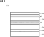
- FIG. 5 is a sectional view illustrating an ultraviolet semiconductor light emitting device according to a second embodiment.
- the second embodiment is substantially the same as the first embodiment except that a second conductive semiconductor layer 47 is formed between a third conductive semiconductor layer 23 and a fourth conductive semiconductor layer 25.
- the ultraviolet semiconductor light emitting device 10A may include a substrate 11, a buffer layer 13, a first conductive semiconductor layer 15, an active layer 19, a second conductive semiconductor layer 47, a third conductive semiconductor layer 23, and a fourth conductive semiconductor layer 25.
- the second conductive semiconductor layer 47 may be or not formed on the active layer 19, but the embodiment is not limited thereto.
- the second conductive semiconductor layer 47 may be formed on the third conductive semiconductor layer 23 and the fourth conductive semiconductor layer 25 may be formed on the second conductive semiconductor layer 47.
- the second conductive semiconductor layer 47 may be formed between the third conductive semiconductor layer 23 and the fourth conductive semiconductor 25.
- the ultraviolet light generated from the active layer 19 may be travelled in all directions. A part of the ultraviolet light may be travelled to the second conductive semiconductor layer 47 via the third conductive semiconductor layer 23.
- the ultraviolet light travelled to the second conductive semiconductor layer 47 is blocked by the second conductive semiconductor layer 47 so that the ultraviolet light is not travelled to the fourth conductive semiconductor layer 25 including GaN capable of absorbing the ultraviolet light.
- the fourth conductive semiconductor layer 25 including GaN capable of absorbing the ultraviolet light may be prevented.
- the second conductive semiconductor layer 47 may reflect the ultraviolet light passing through the third conductive semiconductor layer 23 such that the ultraviolet light can be travelled again to the active layer 19 or the first conductive semiconductor layer 15.
- the ultraviolet light passing through the third conductive semiconductor layer 23 is blocked by the second conductive semiconductor layer 47 and is reflected from the second conductive semiconductor 47 so that the external quantum efficiency may be improved.
- the second conductive semiconductor layer 47 may be formed between the active 19 and the third conductive semiconductor layer 23 and between the third conductive semiconductor layer 23 and the fourth conductive semiconductor layer 25.
- the second conductive semiconductor layer 47 having a reflective function is formed at at least two regions, the light generated from the active layer 19 is prevented from being travelled to the fourth conductive semiconductor layer 25 to minimize optical loss so that the external quantum efficiency may be maximized.
- FIG. 6 is a sectional view illustrating an ultraviolet semiconductor light emitting device according to a third embodiment.
- the second conductive semiconductor layer 21 on the active layer 19 may include a plurality of patterns 51.
- Each of the patterns 51 may include a plurality of pair layers 53 and 55 in which the first layers 53a, 55a, and 57a and the second layers 53b and 55b are paired.
- the first layers 53a, 55a, and 57a and the second layers 53b and 55b may be understood from the first embodiment, and thus a detailed description thereof is omitted.
- the patterns 51 may have a polygonal shape including a triangular shape, a square shape, a pentagonal shape, and a hexagonal shape ( FIG. 8A ), but the embodiment is not limited thereto.
- the patterns 51 may has a circular shape ( FIG. 8B ) or a cylindrical shape, but the embodiment is not limited thereto.
- the patterns 51 may be uniformly or randomly disposed.
- a side of the pattern 51 may be inclined with respect to a horizontal line, for example, a top surface of the active layer 19, but the embodiment is not limited thereto.
- a width of the pattern 51 may become gradually reduced upward. That is, among the first layers 53a, 55a, and 57a and the second layers 53b and 55b, widths of layers located at an upper position may be smaller than widths of layers located at a lower position.
- a width of the pattern 51 may become gradually increased upward. That is, among the first layers 53a, 55a, and 57a and the second layers 53b and 55b, the widths of layers located at the upper position may be larger than the widths of layers located at the lower position.
- the side of the pattern 51 may be perpendicular to the top surface of the active layer 19, but the embodiment is not limited thereto.
- the widths of the layers 53a, 53b, 55a, 55b, 57a may be the same as each other.
- FIG. 7 is a sectional view illustrating a detailed configuration of a second conductive semiconductor layer of FIG. 6 .
- an interval B between the patterns 51 may be smaller than a width A of the pattern 51, but the embodiment is not limited thereto.
- the width A of the pattern 51 may be in the range of 0.5 ⁇ m to 1 ⁇ m, and the interval B of the patterns 51 may be in the range of 1 ⁇ m to 2 ⁇ m.
- the third conductive semiconductor layer 59 may be formed on the top surface of the active layer 19 between the patterns 51 of the second conductive semiconductor layer 21 and top surfaces of the patterns.
- the third conductive semiconductor layer 59 may make contact with the top surface of the active layer 19 between the patterns 51 and be formed on sides and top surfaces of the pattern 51.
- the third conductive semiconductor layer 59 may be grown from the top surface of the active layer 19 between the patterns 51.
- the third conductive semiconductor layer 59 may be grown from the top surfaces of the patterns 51 as well as in a space between the patterns 51.
- the third conductive semiconductor layer 59 and the active layer 19, for example, barrier layers in a multi-quantum well structure may include the same group III-V or group II-VI compound semiconductor material.
- a barrier layer of the active layer 19 and the third conductive semiconductor layer 59 may include AlGaN in common, but the embodiment is not limited thereto.
- barrier layers of the third conductive semiconductor layer 59 and the active layer 19 may include the same group III-V or group II-VI compound semiconductor material, the third conductive semiconductor layer 59 may be stably grown without crack from the active layer 19 between the patterns 51 of the second conductive semiconductor layer 21.
- holes of the fourth conductive semiconductor layer 25 may be provided to the active layer 19 through the third conductive semiconductor layer 59 between the patterns 51 of the second conductive semiconductor layer 21 without passing through the patterns 51 of the second conductive semiconductor layer 21, light efficiency may be improved caused by improvement in current injection efficiency.
- the second conductive semiconductor layer 21 includes a plurality of patterns 51 to further improve reflective efficiency of the ultraviolet light.
- the third conductive semiconductor layer 59 may not be formed.
- the fourth conductive semiconductor layer 25 may make contact with top surfaces of the patterns 51 of the second conductive semiconductor layer 21 and a top surface of the active layer 19 between the patterns 51 of the second conductive semiconductor layer 21.
- the third embodiment may be associated with the first embodiment. That is, the third embodiment may be prepared by forming the second conductive semiconductor layer 21 of the first embodiment including a plurality of patterns 51.
- a second conductive semiconductor layer having a plurality of patterns is applicable to the second embodiment. That is, the second conductive semiconductor layer 47 of the second embodiment has a plurality of patterns, and the fourth conductive semiconductor layer 25 may make contact with a top surface of the third conductive semiconductor layer 23 between the patterns and top surfaces of the patterns, but the embodiment is not limited thereto.
- the second conductive semiconductor layer functioning as a reflective layer is formed between the active layer and the fourth conductive semiconductor layer, so that the ultraviolet light of the active layer is reflected from the second conductive semiconductor layer, thereby maximizing the external quantum efficiency.
- holes of the fourth conductive semiconductor layer may be provided to the active layer via the third conductive semiconductor layer between the patterns of the second conductive semiconductor layer without passing through the patterns of the second conductive semiconductor layer according to the second conductive semiconductor layer, current spreading effect may be improved.
- the second conductive semiconductor layer has a plurality of patterns so that the reflective efficiency of the ultraviolet light may be further improved due to the patterns.
- the ultraviolet semiconductor light emitting devices 10, 10A, and 10B may be fabricated as a package using a molding member including a fluorescent material or a lighting system with the package.
- the ultraviolet light thereof must be converted to visible light.
- any reference in this specification to "one embodiment,” “an embodiment,” “example embodiment,” etc. means that a particular feature, structure, or characteristic described in connection with the embodiment is included in at least one embodiment of the invention.
- the appearances of such phrases in various places in the specification are not necessarily all referring to the same embodiment.
Landscapes
- Engineering & Computer Science (AREA)
- Manufacturing & Machinery (AREA)
- Computer Hardware Design (AREA)
- Microelectronics & Electronic Packaging (AREA)
- Power Engineering (AREA)
- Led Devices (AREA)
Applications Claiming Priority (2)
| Application Number | Priority Date | Filing Date | Title |
|---|---|---|---|
| KR1020110124452A KR101981119B1 (ko) | 2011-11-25 | 2011-11-25 | 자외선 반도체 발광 소자 |
| EP12193953.2A EP2597686B1 (fr) | 2011-11-25 | 2012-11-23 | Dispositif électroluminescent semi-conducteur à ultra-violet |
Related Parent Applications (1)
| Application Number | Title | Priority Date | Filing Date |
|---|---|---|---|
| EP12193953.2A Division EP2597686B1 (fr) | 2011-11-25 | 2012-11-23 | Dispositif électroluminescent semi-conducteur à ultra-violet |
Publications (2)
| Publication Number | Publication Date |
|---|---|
| EP3346510A1 true EP3346510A1 (fr) | 2018-07-11 |
| EP3346510B1 EP3346510B1 (fr) | 2021-11-17 |
Family
ID=47216140
Family Applications (2)
| Application Number | Title | Priority Date | Filing Date |
|---|---|---|---|
| EP18154218.4A Active EP3346510B1 (fr) | 2011-11-25 | 2012-11-23 | Dispositif électroluminescent semi-conducteur de lumière ultraviolet |
| EP12193953.2A Active EP2597686B1 (fr) | 2011-11-25 | 2012-11-23 | Dispositif électroluminescent semi-conducteur à ultra-violet |
Family Applications After (1)
| Application Number | Title | Priority Date | Filing Date |
|---|---|---|---|
| EP12193953.2A Active EP2597686B1 (fr) | 2011-11-25 | 2012-11-23 | Dispositif électroluminescent semi-conducteur à ultra-violet |
Country Status (6)
| Country | Link |
|---|---|
| US (1) | US20130146906A1 (fr) |
| EP (2) | EP3346510B1 (fr) |
| JP (1) | JP2013115435A (fr) |
| KR (1) | KR101981119B1 (fr) |
| CN (1) | CN103137806B (fr) |
| TW (1) | TWI572056B (fr) |
Families Citing this family (6)
| Publication number | Priority date | Publication date | Assignee | Title |
|---|---|---|---|---|
| KR102119731B1 (ko) * | 2013-11-26 | 2020-06-08 | 엘지이노텍 주식회사 | 발광소자 |
| KR102142714B1 (ko) * | 2014-02-18 | 2020-08-07 | 엘지이노텍 주식회사 | 자외선 발광소자 및 이를 구비하는 발광소자 패키지 |
| KR20170108321A (ko) * | 2016-03-17 | 2017-09-27 | 주식회사 루멘스 | 발광 다이오드 |
| WO2019071586A1 (fr) * | 2017-10-13 | 2019-04-18 | 深圳前海小有技术有限公司 | Structure électroluminescente à del ultraviolette profonde et dispositif électroluminescent |
| KR20200088934A (ko) * | 2019-01-15 | 2020-07-24 | 삼성디스플레이 주식회사 | 발광 소자 및 이를 포함하는 표시 장치 |
| CN114512580B (zh) * | 2021-12-22 | 2023-09-22 | 淮安澳洋顺昌光电技术有限公司 | 一种发光二极管 |
Citations (5)
| Publication number | Priority date | Publication date | Assignee | Title |
|---|---|---|---|---|
| US20040099869A1 (en) * | 2002-11-21 | 2004-05-27 | Remigijus Gaska | Light emitting heterostructure |
| US20080277681A1 (en) * | 2007-05-09 | 2008-11-13 | Tsinghua University | Light emitting diode |
| US20100123118A1 (en) * | 2008-11-20 | 2010-05-20 | Shenzhen Century Epitech Leds Co., Ltd. | LED Epitaxial Wafer with Patterned GaN based Substrate and Manufacturing Method For the Same |
| US20110049549A1 (en) * | 2009-08-26 | 2011-03-03 | Samsung Electronics Co., Ltd. | Light emitting devices and methods of manufacturing the same |
| KR20110124452A (ko) | 2010-05-11 | 2011-11-17 | 한국전기안전공사 | 광파 측정기술을 이용한 비주얼 피뢰진단 시스템 및 그 방법 |
Family Cites Families (25)
| Publication number | Priority date | Publication date | Assignee | Title |
|---|---|---|---|---|
| US4786951A (en) * | 1985-02-12 | 1988-11-22 | Mitsubishi Denki Kabushiki Kaisha | Semiconductor optical element and a process for producing the same |
| JPH09232631A (ja) * | 1996-02-27 | 1997-09-05 | Sumitomo Chem Co Ltd | 3−5族化合物半導体発光素子 |
| EP0856202A2 (fr) * | 1996-06-11 | 1998-08-05 | Koninklijke Philips Electronics N.V. | Dispositifs emettant de la lumiere visible, y compris des diodes emettant de la lumiere ultraviolette et des elements fluorescents excitables par les ultraviolets et emettant de la lumiere visible et procede de production de tels dispositifs |
| JPH1065209A (ja) * | 1996-08-20 | 1998-03-06 | Fujitsu Ltd | 半導体電磁波発生装置 |
| GB9807692D0 (en) * | 1998-04-14 | 1998-06-10 | Univ Strathclyde | Optival devices |
| GB2344456B (en) * | 1998-12-02 | 2000-12-27 | Arima Optoelectronics Corp | Semiconductor devices |
| US6376864B1 (en) * | 1999-07-06 | 2002-04-23 | Tien Yang Wang | Semiconductor light-emitting device and method for manufacturing the same |
| JP3842976B2 (ja) * | 2000-03-17 | 2006-11-08 | 富士通株式会社 | 分布帰還型半導体レーザとその製造方法 |
| US6711203B1 (en) * | 2000-09-22 | 2004-03-23 | Blueleaf, Inc. | Optical transmitter comprising a stepwise tunable laser |
| JP2003017745A (ja) * | 2001-06-29 | 2003-01-17 | Shiro Sakai | 窒化ガリウム系発光素子 |
| JP2003115635A (ja) * | 2001-08-03 | 2003-04-18 | Furukawa Electric Co Ltd:The | 面発光型半導体レーザ素子 |
| JP2005311072A (ja) * | 2004-04-21 | 2005-11-04 | Matsushita Electric Ind Co Ltd | 発光素子および照明装置 |
| US20060006793A1 (en) * | 2004-07-12 | 2006-01-12 | Baroky Tajul A | Deep ultraviolet used to produce white light |
| KR100576870B1 (ko) * | 2004-08-11 | 2006-05-10 | 삼성전기주식회사 | 질화물 반도체 발광소자 및 제조방법 |
| JP2006100420A (ja) * | 2004-09-28 | 2006-04-13 | Toyoda Gosei Co Ltd | Iii族窒化物系化合物半導体発光素子 |
| DE102004057802B4 (de) * | 2004-11-30 | 2011-03-24 | Osram Opto Semiconductors Gmbh | Strahlungemittierendes Halbleiterbauelement mit Zwischenschicht |
| JP2006332205A (ja) * | 2005-05-24 | 2006-12-07 | Rohm Co Ltd | 窒化物半導体発光素子 |
| DE102006004591A1 (de) * | 2005-09-29 | 2007-04-05 | Osram Opto Semiconductors Gmbh | Strahlungsemittierender Halbleiterchip |
| JP2007150074A (ja) * | 2005-11-29 | 2007-06-14 | Rohm Co Ltd | 窒化物半導体発光素子 |
| US20090001389A1 (en) * | 2007-06-28 | 2009-01-01 | Motorola, Inc. | Hybrid vertical cavity of multiple wavelength leds |
| TWI370558B (en) * | 2007-11-07 | 2012-08-11 | Ind Tech Res Inst | Light emitting diode and process for fabricating the same |
| CN101986667A (zh) * | 2009-07-28 | 2011-03-16 | 深圳富泰宏精密工业有限公司 | 便携式电子装置 |
| KR101654340B1 (ko) * | 2009-12-28 | 2016-09-06 | 서울바이오시스 주식회사 | 발광 다이오드 |
| KR101122020B1 (ko) * | 2010-03-17 | 2012-03-09 | 한국광기술원 | 다중발광소자 및 이를 제조하는 방법 |
| KR101666442B1 (ko) * | 2010-03-25 | 2016-10-17 | 엘지이노텍 주식회사 | 발광 다이오드 및 이를 포함하는 발광 소자 패키지 |
-
2011
- 2011-11-25 KR KR1020110124452A patent/KR101981119B1/ko active IP Right Grant
-
2012
- 2012-11-22 JP JP2012256905A patent/JP2013115435A/ja active Pending
- 2012-11-23 EP EP18154218.4A patent/EP3346510B1/fr active Active
- 2012-11-23 EP EP12193953.2A patent/EP2597686B1/fr active Active
- 2012-11-26 US US13/685,337 patent/US20130146906A1/en not_active Abandoned
- 2012-11-26 CN CN201210488183.7A patent/CN103137806B/zh active Active
- 2012-11-26 TW TW101144149A patent/TWI572056B/zh not_active IP Right Cessation
Patent Citations (5)
| Publication number | Priority date | Publication date | Assignee | Title |
|---|---|---|---|---|
| US20040099869A1 (en) * | 2002-11-21 | 2004-05-27 | Remigijus Gaska | Light emitting heterostructure |
| US20080277681A1 (en) * | 2007-05-09 | 2008-11-13 | Tsinghua University | Light emitting diode |
| US20100123118A1 (en) * | 2008-11-20 | 2010-05-20 | Shenzhen Century Epitech Leds Co., Ltd. | LED Epitaxial Wafer with Patterned GaN based Substrate and Manufacturing Method For the Same |
| US20110049549A1 (en) * | 2009-08-26 | 2011-03-03 | Samsung Electronics Co., Ltd. | Light emitting devices and methods of manufacturing the same |
| KR20110124452A (ko) | 2010-05-11 | 2011-11-17 | 한국전기안전공사 | 광파 측정기술을 이용한 비주얼 피뢰진단 시스템 및 그 방법 |
Also Published As
| Publication number | Publication date |
|---|---|
| JP2013115435A (ja) | 2013-06-10 |
| TW201332144A (zh) | 2013-08-01 |
| TWI572056B (zh) | 2017-02-21 |
| EP2597686A1 (fr) | 2013-05-29 |
| CN103137806A (zh) | 2013-06-05 |
| CN103137806B (zh) | 2017-07-18 |
| EP2597686B1 (fr) | 2018-01-31 |
| US20130146906A1 (en) | 2013-06-13 |
| KR20130058444A (ko) | 2013-06-04 |
| EP3346510B1 (fr) | 2021-11-17 |
| KR101981119B1 (ko) | 2019-05-22 |
Similar Documents
| Publication | Publication Date | Title |
|---|---|---|
| KR100993085B1 (ko) | 발광 소자, 발광 소자 패키지 및 라이트 유닛 | |
| US10475960B2 (en) | Light emitting device having gallium nitrade substrate | |
| CN102569589B (zh) | 半导体发光元件 | |
| US9548416B2 (en) | Light emitting device and light emitting device package having the same | |
| JP6117541B2 (ja) | 紫外線発光素子 | |
| EP2597686B1 (fr) | Dispositif électroluminescent semi-conducteur à ultra-violet | |
| TWI446598B (zh) | 半導體發光元件、燈、電子機器及機械裝置 | |
| US20130126829A1 (en) | High efficiency light emitting diode | |
| KR20170037565A (ko) | 발광소자, 발광소자 패키지 및 발광장치 | |
| WO2014192226A1 (fr) | Élément électroluminescent | |
| CN108431970B (zh) | 发光元件 | |
| US9112092B2 (en) | Light emitting device and light emitting device package | |
| KR20120055332A (ko) | 발광소자 및 발광소자 패키지 | |
| JP2011071340A (ja) | 発光素子 | |
| KR102397266B1 (ko) | 발광소자 및 조명장치 | |
| KR20130074080A (ko) | 자외선 발광 소자 | |
| KR102034710B1 (ko) | 발광 소자 | |
| KR101781217B1 (ko) | 발광 소자 및 발광 소자 패키지 | |
| KR102673668B1 (ko) | 발광 소자 및 이의 제조 방법 | |
| JP6747308B2 (ja) | 発光素子 | |
| KR20130061589A (ko) | 자외선 발광 소자 | |
| KR20160046186A (ko) | 발광소자 및 조명시스템 | |
| KR20120049694A (ko) | 발광소자 및 발광소자 패키지 | |
| KR20120065676A (ko) | 발광소자의 제조방법 | |
| KR20140107868A (ko) | 발광 영역을 분리하는 세퍼레이션층을 포함하는 반도체 발광소자 |
Legal Events
| Date | Code | Title | Description |
|---|---|---|---|
| PUAI | Public reference made under article 153(3) epc to a published international application that has entered the european phase |
Free format text: ORIGINAL CODE: 0009012 |
|
| STAA | Information on the status of an ep patent application or granted ep patent |
Free format text: STATUS: THE APPLICATION HAS BEEN PUBLISHED |
|
| AC | Divisional application: reference to earlier application |
Ref document number: 2597686 Country of ref document: EP Kind code of ref document: P |
|
| AK | Designated contracting states |
Kind code of ref document: A1 Designated state(s): AL AT BE BG CH CY CZ DE DK EE ES FI FR GB GR HR HU IE IS IT LI LT LU LV MC MK MT NL NO PL PT RO RS SE SI SK SM TR |
|
| STAA | Information on the status of an ep patent application or granted ep patent |
Free format text: STATUS: REQUEST FOR EXAMINATION WAS MADE |
|
| 17P | Request for examination filed |
Effective date: 20190110 |
|
| RBV | Designated contracting states (corrected) |
Designated state(s): AL AT BE BG CH CY CZ DE DK EE ES FI FR GB GR HR HU IE IS IT LI LT LU LV MC MK MT NL NO PL PT RO RS SE SI SK SM TR |
|
| STAA | Information on the status of an ep patent application or granted ep patent |
Free format text: STATUS: EXAMINATION IS IN PROGRESS |
|
| 17Q | First examination report despatched |
Effective date: 20191126 |
|
| STAA | Information on the status of an ep patent application or granted ep patent |
Free format text: STATUS: EXAMINATION IS IN PROGRESS |
|
| RIC1 | Information provided on ipc code assigned before grant |
Ipc: H01L 33/10 20100101AFI20210419BHEP Ipc: H01L 33/40 20100101ALN20210419BHEP Ipc: H01L 33/46 20100101ALN20210419BHEP |
|
| GRAP | Despatch of communication of intention to grant a patent |
Free format text: ORIGINAL CODE: EPIDOSNIGR1 |
|
| STAA | Information on the status of an ep patent application or granted ep patent |
Free format text: STATUS: GRANT OF PATENT IS INTENDED |
|
| RIC1 | Information provided on ipc code assigned before grant |
Ipc: H01L 33/10 20100101AFI20210604BHEP Ipc: H01L 33/40 20100101ALN20210604BHEP Ipc: H01L 33/46 20100101ALN20210604BHEP |
|
| INTG | Intention to grant announced |
Effective date: 20210625 |
|
| RAP1 | Party data changed (applicant data changed or rights of an application transferred) |
Owner name: SUZHOU LEKIN SEMICONDUCTOR CO., LTD. |
|
| GRAS | Grant fee paid |
Free format text: ORIGINAL CODE: EPIDOSNIGR3 |
|
| GRAA | (expected) grant |
Free format text: ORIGINAL CODE: 0009210 |
|
| STAA | Information on the status of an ep patent application or granted ep patent |
Free format text: STATUS: THE PATENT HAS BEEN GRANTED |
|
| AC | Divisional application: reference to earlier application |
Ref document number: 2597686 Country of ref document: EP Kind code of ref document: P |
|
| AK | Designated contracting states |
Kind code of ref document: B1 Designated state(s): AL AT BE BG CH CY CZ DE DK EE ES FI FR GB GR HR HU IE IS IT LI LT LU LV MC MK MT NL NO PL PT RO RS SE SI SK SM TR |
|
| REG | Reference to a national code |
Ref country code: GB Ref legal event code: FG4D |
|
| REG | Reference to a national code |
Ref country code: DE Ref legal event code: R096 Ref document number: 602012077204 Country of ref document: DE |
|
| REG | Reference to a national code |
Ref country code: IE Ref legal event code: FG4D |
|
| REG | Reference to a national code |
Ref country code: AT Ref legal event code: REF Ref document number: 1448782 Country of ref document: AT Kind code of ref document: T Effective date: 20211215 |
|
| REG | Reference to a national code |
Ref country code: NL Ref legal event code: FP |
|
| REG | Reference to a national code |
Ref country code: LT Ref legal event code: MG9D |
|
| REG | Reference to a national code |
Ref country code: AT Ref legal event code: MK05 Ref document number: 1448782 Country of ref document: AT Kind code of ref document: T Effective date: 20211117 |
|
| PG25 | Lapsed in a contracting state [announced via postgrant information from national office to epo] |
Ref country code: RS Free format text: LAPSE BECAUSE OF FAILURE TO SUBMIT A TRANSLATION OF THE DESCRIPTION OR TO PAY THE FEE WITHIN THE PRESCRIBED TIME-LIMIT Effective date: 20211117 Ref country code: LT Free format text: LAPSE BECAUSE OF FAILURE TO SUBMIT A TRANSLATION OF THE DESCRIPTION OR TO PAY THE FEE WITHIN THE PRESCRIBED TIME-LIMIT Effective date: 20211117 Ref country code: FI Free format text: LAPSE BECAUSE OF FAILURE TO SUBMIT A TRANSLATION OF THE DESCRIPTION OR TO PAY THE FEE WITHIN THE PRESCRIBED TIME-LIMIT Effective date: 20211117 Ref country code: BG Free format text: LAPSE BECAUSE OF FAILURE TO SUBMIT A TRANSLATION OF THE DESCRIPTION OR TO PAY THE FEE WITHIN THE PRESCRIBED TIME-LIMIT Effective date: 20220217 Ref country code: AT Free format text: LAPSE BECAUSE OF FAILURE TO SUBMIT A TRANSLATION OF THE DESCRIPTION OR TO PAY THE FEE WITHIN THE PRESCRIBED TIME-LIMIT Effective date: 20211117 |
|
| PG25 | Lapsed in a contracting state [announced via postgrant information from national office to epo] |
Ref country code: IS Free format text: LAPSE BECAUSE OF FAILURE TO SUBMIT A TRANSLATION OF THE DESCRIPTION OR TO PAY THE FEE WITHIN THE PRESCRIBED TIME-LIMIT Effective date: 20220317 Ref country code: SE Free format text: LAPSE BECAUSE OF FAILURE TO SUBMIT A TRANSLATION OF THE DESCRIPTION OR TO PAY THE FEE WITHIN THE PRESCRIBED TIME-LIMIT Effective date: 20211117 Ref country code: PT Free format text: LAPSE BECAUSE OF FAILURE TO SUBMIT A TRANSLATION OF THE DESCRIPTION OR TO PAY THE FEE WITHIN THE PRESCRIBED TIME-LIMIT Effective date: 20220317 Ref country code: PL Free format text: LAPSE BECAUSE OF FAILURE TO SUBMIT A TRANSLATION OF THE DESCRIPTION OR TO PAY THE FEE WITHIN THE PRESCRIBED TIME-LIMIT Effective date: 20211117 Ref country code: NO Free format text: LAPSE BECAUSE OF FAILURE TO SUBMIT A TRANSLATION OF THE DESCRIPTION OR TO PAY THE FEE WITHIN THE PRESCRIBED TIME-LIMIT Effective date: 20220217 Ref country code: LV Free format text: LAPSE BECAUSE OF FAILURE TO SUBMIT A TRANSLATION OF THE DESCRIPTION OR TO PAY THE FEE WITHIN THE PRESCRIBED TIME-LIMIT Effective date: 20211117 Ref country code: HR Free format text: LAPSE BECAUSE OF FAILURE TO SUBMIT A TRANSLATION OF THE DESCRIPTION OR TO PAY THE FEE WITHIN THE PRESCRIBED TIME-LIMIT Effective date: 20211117 Ref country code: GR Free format text: LAPSE BECAUSE OF FAILURE TO SUBMIT A TRANSLATION OF THE DESCRIPTION OR TO PAY THE FEE WITHIN THE PRESCRIBED TIME-LIMIT Effective date: 20220218 Ref country code: ES Free format text: LAPSE BECAUSE OF FAILURE TO SUBMIT A TRANSLATION OF THE DESCRIPTION OR TO PAY THE FEE WITHIN THE PRESCRIBED TIME-LIMIT Effective date: 20211117 |
|
| REG | Reference to a national code |
Ref country code: CH Ref legal event code: PL |
|
| PG25 | Lapsed in a contracting state [announced via postgrant information from national office to epo] |
Ref country code: SM Free format text: LAPSE BECAUSE OF FAILURE TO SUBMIT A TRANSLATION OF THE DESCRIPTION OR TO PAY THE FEE WITHIN THE PRESCRIBED TIME-LIMIT Effective date: 20211117 Ref country code: SK Free format text: LAPSE BECAUSE OF FAILURE TO SUBMIT A TRANSLATION OF THE DESCRIPTION OR TO PAY THE FEE WITHIN THE PRESCRIBED TIME-LIMIT Effective date: 20211117 Ref country code: RO Free format text: LAPSE BECAUSE OF FAILURE TO SUBMIT A TRANSLATION OF THE DESCRIPTION OR TO PAY THE FEE WITHIN THE PRESCRIBED TIME-LIMIT Effective date: 20211117 Ref country code: LU Free format text: LAPSE BECAUSE OF NON-PAYMENT OF DUE FEES Effective date: 20211123 Ref country code: EE Free format text: LAPSE BECAUSE OF FAILURE TO SUBMIT A TRANSLATION OF THE DESCRIPTION OR TO PAY THE FEE WITHIN THE PRESCRIBED TIME-LIMIT Effective date: 20211117 Ref country code: DK Free format text: LAPSE BECAUSE OF FAILURE TO SUBMIT A TRANSLATION OF THE DESCRIPTION OR TO PAY THE FEE WITHIN THE PRESCRIBED TIME-LIMIT Effective date: 20211117 Ref country code: CZ Free format text: LAPSE BECAUSE OF FAILURE TO SUBMIT A TRANSLATION OF THE DESCRIPTION OR TO PAY THE FEE WITHIN THE PRESCRIBED TIME-LIMIT Effective date: 20211117 Ref country code: BE Free format text: LAPSE BECAUSE OF NON-PAYMENT OF DUE FEES Effective date: 20211130 |
|
| REG | Reference to a national code |
Ref country code: BE Ref legal event code: MM Effective date: 20211130 |
|
| REG | Reference to a national code |
Ref country code: DE Ref legal event code: R097 Ref document number: 602012077204 Country of ref document: DE |
|
| PG25 | Lapsed in a contracting state [announced via postgrant information from national office to epo] |
Ref country code: MC Free format text: LAPSE BECAUSE OF FAILURE TO SUBMIT A TRANSLATION OF THE DESCRIPTION OR TO PAY THE FEE WITHIN THE PRESCRIBED TIME-LIMIT Effective date: 20211117 |
|
| PLBE | No opposition filed within time limit |
Free format text: ORIGINAL CODE: 0009261 |
|
| STAA | Information on the status of an ep patent application or granted ep patent |
Free format text: STATUS: NO OPPOSITION FILED WITHIN TIME LIMIT |
|
| 26N | No opposition filed |
Effective date: 20220818 |
|
| PG25 | Lapsed in a contracting state [announced via postgrant information from national office to epo] |
Ref country code: IE Free format text: LAPSE BECAUSE OF NON-PAYMENT OF DUE FEES Effective date: 20211123 Ref country code: AL Free format text: LAPSE BECAUSE OF FAILURE TO SUBMIT A TRANSLATION OF THE DESCRIPTION OR TO PAY THE FEE WITHIN THE PRESCRIBED TIME-LIMIT Effective date: 20211117 |
|
| PG25 | Lapsed in a contracting state [announced via postgrant information from national office to epo] |
Ref country code: SI Free format text: LAPSE BECAUSE OF FAILURE TO SUBMIT A TRANSLATION OF THE DESCRIPTION OR TO PAY THE FEE WITHIN THE PRESCRIBED TIME-LIMIT Effective date: 20211117 |
|
| PG25 | Lapsed in a contracting state [announced via postgrant information from national office to epo] |
Ref country code: IT Free format text: LAPSE BECAUSE OF FAILURE TO SUBMIT A TRANSLATION OF THE DESCRIPTION OR TO PAY THE FEE WITHIN THE PRESCRIBED TIME-LIMIT Effective date: 20211117 Ref country code: HU Free format text: LAPSE BECAUSE OF FAILURE TO SUBMIT A TRANSLATION OF THE DESCRIPTION OR TO PAY THE FEE WITHIN THE PRESCRIBED TIME-LIMIT; INVALID AB INITIO Effective date: 20121123 Ref country code: CY Free format text: LAPSE BECAUSE OF FAILURE TO SUBMIT A TRANSLATION OF THE DESCRIPTION OR TO PAY THE FEE WITHIN THE PRESCRIBED TIME-LIMIT Effective date: 20211117 |
|
| PG25 | Lapsed in a contracting state [announced via postgrant information from national office to epo] |
Ref country code: LI Free format text: LAPSE BECAUSE OF NON-PAYMENT OF DUE FEES Effective date: 20220701 Ref country code: CH Free format text: LAPSE BECAUSE OF NON-PAYMENT OF DUE FEES Effective date: 20220701 |
|
| PGFP | Annual fee paid to national office [announced via postgrant information from national office to epo] |
Ref country code: NL Payment date: 20231013 Year of fee payment: 12 |
|
| PGFP | Annual fee paid to national office [announced via postgrant information from national office to epo] |
Ref country code: GB Payment date: 20231006 Year of fee payment: 12 |
|
| PGFP | Annual fee paid to national office [announced via postgrant information from national office to epo] |
Ref country code: FR Payment date: 20231009 Year of fee payment: 12 Ref country code: DE Payment date: 20231003 Year of fee payment: 12 |
|
| PG25 | Lapsed in a contracting state [announced via postgrant information from national office to epo] |
Ref country code: MK Free format text: LAPSE BECAUSE OF FAILURE TO SUBMIT A TRANSLATION OF THE DESCRIPTION OR TO PAY THE FEE WITHIN THE PRESCRIBED TIME-LIMIT Effective date: 20211117 |
|
| PG25 | Lapsed in a contracting state [announced via postgrant information from national office to epo] |
Ref country code: TR Free format text: LAPSE BECAUSE OF FAILURE TO SUBMIT A TRANSLATION OF THE DESCRIPTION OR TO PAY THE FEE WITHIN THE PRESCRIBED TIME-LIMIT Effective date: 20211117 |