EP3346068B2 - Fugendichtungsband umfassend einen schaumstoff - Google Patents
Fugendichtungsband umfassend einen schaumstoff Download PDFInfo
- Publication number
- EP3346068B2 EP3346068B2 EP17150725.4A EP17150725A EP3346068B2 EP 3346068 B2 EP3346068 B2 EP 3346068B2 EP 17150725 A EP17150725 A EP 17150725A EP 3346068 B2 EP3346068 B2 EP 3346068B2
- Authority
- EP
- European Patent Office
- Prior art keywords
- foam
- aerogel
- joint sealing
- sealing tape
- substance
- Prior art date
- Legal status (The legal status is an assumption and is not a legal conclusion. Google has not performed a legal analysis and makes no representation as to the accuracy of the status listed.)
- Active
Links
Images


Classifications
-
- E—FIXED CONSTRUCTIONS
- E04—BUILDING
- E04B—GENERAL BUILDING CONSTRUCTIONS; WALLS, e.g. PARTITIONS; ROOFS; FLOORS; CEILINGS; INSULATION OR OTHER PROTECTION OF BUILDINGS
- E04B1/00—Constructions in general; Structures which are not restricted either to walls, e.g. partitions, or floors or ceilings or roofs
- E04B1/62—Insulation or other protection; Elements or use of specified material therefor
- E04B1/66—Sealings
- E04B1/68—Sealings of joints, e.g. expansion joints
- E04B1/6812—Compressable seals of solid form
-
- C—CHEMISTRY; METALLURGY
- C08—ORGANIC MACROMOLECULAR COMPOUNDS; THEIR PREPARATION OR CHEMICAL WORKING-UP; COMPOSITIONS BASED THEREON
- C08J—WORKING-UP; GENERAL PROCESSES OF COMPOUNDING; AFTER-TREATMENT NOT COVERED BY SUBCLASSES C08B, C08C, C08F, C08G or C08H
- C08J9/00—Working-up of macromolecular substances to porous or cellular articles or materials; After-treatment thereof
- C08J9/36—After-treatment
- C08J9/40—Impregnation
-
- E—FIXED CONSTRUCTIONS
- E06—DOORS, WINDOWS, SHUTTERS, OR ROLLER BLINDS IN GENERAL; LADDERS
- E06B—FIXED OR MOVABLE CLOSURES FOR OPENINGS IN BUILDINGS, VEHICLES, FENCES OR LIKE ENCLOSURES IN GENERAL, e.g. DOORS, WINDOWS, BLINDS, GATES
- E06B1/00—Border constructions of openings in walls, floors, or ceilings; Frames to be rigidly mounted in such openings
- E06B1/62—Tightening or covering joints between the border of openings and the frame or between contiguous frames
-
- B—PERFORMING OPERATIONS; TRANSPORTING
- B29—WORKING OF PLASTICS; WORKING OF SUBSTANCES IN A PLASTIC STATE IN GENERAL
- B29C—SHAPING OR JOINING OF PLASTICS; SHAPING OF MATERIAL IN A PLASTIC STATE, NOT OTHERWISE PROVIDED FOR; AFTER-TREATMENT OF THE SHAPED PRODUCTS, e.g. REPAIRING
- B29C44/00—Shaping by internal pressure generated in the material, e.g. swelling or foaming ; Producing porous or cellular expanded plastics articles
- B29C44/34—Auxiliary operations
- B29C44/56—After-treatment of articles, e.g. for altering the shape
- B29C44/5618—Impregnating foam articles
-
- B—PERFORMING OPERATIONS; TRANSPORTING
- B29—WORKING OF PLASTICS; WORKING OF SUBSTANCES IN A PLASTIC STATE IN GENERAL
- B29K—INDEXING SCHEME ASSOCIATED WITH SUBCLASSES B29B, B29C OR B29D, RELATING TO MOULDING MATERIALS OR TO MATERIALS FOR MOULDS, REINFORCEMENTS, FILLERS OR PREFORMED PARTS, e.g. INSERTS
- B29K2075/00—Use of PU, i.e. polyureas or polyurethanes or derivatives thereof, as moulding material
-
- B—PERFORMING OPERATIONS; TRANSPORTING
- B29—WORKING OF PLASTICS; WORKING OF SUBSTANCES IN A PLASTIC STATE IN GENERAL
- B29K—INDEXING SCHEME ASSOCIATED WITH SUBCLASSES B29B, B29C OR B29D, RELATING TO MOULDING MATERIALS OR TO MATERIALS FOR MOULDS, REINFORCEMENTS, FILLERS OR PREFORMED PARTS, e.g. INSERTS
- B29K2105/00—Condition, form or state of moulded material or of the material to be shaped
- B29K2105/0058—Liquid or visquous
- B29K2105/0061—Gel or sol
-
- B—PERFORMING OPERATIONS; TRANSPORTING
- B29—WORKING OF PLASTICS; WORKING OF SUBSTANCES IN A PLASTIC STATE IN GENERAL
- B29K—INDEXING SCHEME ASSOCIATED WITH SUBCLASSES B29B, B29C OR B29D, RELATING TO MOULDING MATERIALS OR TO MATERIALS FOR MOULDS, REINFORCEMENTS, FILLERS OR PREFORMED PARTS, e.g. INSERTS
- B29K2105/00—Condition, form or state of moulded material or of the material to be shaped
- B29K2105/04—Condition, form or state of moulded material or of the material to be shaped cellular or porous
- B29K2105/045—Condition, form or state of moulded material or of the material to be shaped cellular or porous with open cells
-
- B—PERFORMING OPERATIONS; TRANSPORTING
- B29—WORKING OF PLASTICS; WORKING OF SUBSTANCES IN A PLASTIC STATE IN GENERAL
- B29K—INDEXING SCHEME ASSOCIATED WITH SUBCLASSES B29B, B29C OR B29D, RELATING TO MOULDING MATERIALS OR TO MATERIALS FOR MOULDS, REINFORCEMENTS, FILLERS OR PREFORMED PARTS, e.g. INSERTS
- B29K2995/00—Properties of moulding materials, reinforcements, fillers, preformed parts or moulds
- B29K2995/0012—Properties of moulding materials, reinforcements, fillers, preformed parts or moulds having particular thermal properties
- B29K2995/0015—Insulating
-
- B—PERFORMING OPERATIONS; TRANSPORTING
- B29—WORKING OF PLASTICS; WORKING OF SUBSTANCES IN A PLASTIC STATE IN GENERAL
- B29K—INDEXING SCHEME ASSOCIATED WITH SUBCLASSES B29B, B29C OR B29D, RELATING TO MOULDING MATERIALS OR TO MATERIALS FOR MOULDS, REINFORCEMENTS, FILLERS OR PREFORMED PARTS, e.g. INSERTS
- B29K2995/00—Properties of moulding materials, reinforcements, fillers, preformed parts or moulds
- B29K2995/0037—Other properties
- B29K2995/0094—Geometrical properties
- B29K2995/0097—Thickness
-
- B—PERFORMING OPERATIONS; TRANSPORTING
- B29—WORKING OF PLASTICS; WORKING OF SUBSTANCES IN A PLASTIC STATE IN GENERAL
- B29L—INDEXING SCHEME ASSOCIATED WITH SUBCLASS B29C, RELATING TO PARTICULAR ARTICLES
- B29L2031/00—Other particular articles
- B29L2031/001—Profiled members, e.g. beams, sections
- B29L2031/003—Profiled members, e.g. beams, sections having a profiled transverse cross-section
- B29L2031/005—Profiled members, e.g. beams, sections having a profiled transverse cross-section for making window frames
- B29L2031/006—Profiled members, e.g. beams, sections having a profiled transverse cross-section for making window frames and provided with a sealing element
-
- B—PERFORMING OPERATIONS; TRANSPORTING
- B29—WORKING OF PLASTICS; WORKING OF SUBSTANCES IN A PLASTIC STATE IN GENERAL
- B29L—INDEXING SCHEME ASSOCIATED WITH SUBCLASS B29C, RELATING TO PARTICULAR ARTICLES
- B29L2031/00—Other particular articles
- B29L2031/26—Sealing devices, e.g. packaging for pistons or pipe joints
-
- E—FIXED CONSTRUCTIONS
- E06—DOORS, WINDOWS, SHUTTERS, OR ROLLER BLINDS IN GENERAL; LADDERS
- E06B—FIXED OR MOVABLE CLOSURES FOR OPENINGS IN BUILDINGS, VEHICLES, FENCES OR LIKE ENCLOSURES IN GENERAL, e.g. DOORS, WINDOWS, BLINDS, GATES
- E06B1/00—Border constructions of openings in walls, floors, or ceilings; Frames to be rigidly mounted in such openings
- E06B1/62—Tightening or covering joints between the border of openings and the frame or between contiguous frames
- E06B2001/626—Tightening or covering joints between the border of openings and the frame or between contiguous frames comprising expanding foam strips
Definitions
- the invention relates to a joint sealing tape comprising a foam.
- Compressible joint sealing tapes which contain a foam, are used for sealing against draughts and driving rain, for example from the DE 19641415 C2 , the DE 20009674 U1 or the WO 2012/167762 A1 and are used in construction technology for sealing in particular components, for example window and door frames, against masonry, for example a building wall opening, or an expansion joint in a facade.
- the aforementioned joint sealing tapes have at least one membrane layer.
- Other joint sealing tapes that do not have a membrane layer are known, for example, from DE 1 000 946 A , EN 40 20 230 A1 or the EN 34 07 995 A1 known.
- DE 20 2012 000883 U1 discloses a joint sealing tape comprising a foam, wherein the foam is equipped with at least one substance, wherein the foam is impregnated with an impregnating compound.
- a known joint sealing tape which comprises a foam, has two long sides and an upper side which, when the joint sealing tape is installed, borders one joint flank, in particular of a brickwork, and an underside which, when the joint sealing tape is installed, borders the opposite joint flank, in particular of the component.
- One or preferably several membrane layers can run in the longitudinal direction between the upper side and the lower side, parallel or almost parallel to the long sides.
- the underside of such a joint sealing tape is glued to the component to be sealed, for example a window or door frame. After the component has been installed, for example in a building wall opening, the previously compressed joint sealing tape expands, i.e.
- Joint sealing tapes of this type are also used for sealing facade joints, especially in existing joints.
- the invention is based on the fundamental task of further developing such joint sealing tapes, but also components thereof, in such a way that they better meet the requirements placed on them with regard to driving rain tightness, vapour diffusion openness, thermal insulation, air tightness and/or fire protection.
- the foam is equipped with at least one substance which reduces the thermal conductivity of the foam or the thermal conductivity of the joint sealing tape comprising the foam.
- a reduction or decrease in thermal conductivity means an improvement in the thermal insulation properties and thus a thermal insulation effect.
- the thermal insulation of a foam containing the at least one substance or of a joint sealing tape containing this substance is therefore better than the thermal insulation of a foam not containing the at least one substance or of a joint sealing tape not containing this substance.
- the use of a foam containing the at least one substance or of a joint sealing tape containing this substance in joints improves thermal insulation and prevents a thermal bridge through the joint.
- Known foams or joint sealing tapes comprising foam that do not contain the at least one substance generally have a higher thermal conductivity in the compressed state than in the uncompressed state due to the reduction in the pore space within the foam.
- Foams or joint sealing tapes comprising foam that may still have a sufficiently low thermal conductivity in the uncompressed state no longer have this in the compressed state.
- the joint sealing tape comprising a foam When the joint sealing tape comprising a foam is installed, it is usually not fully expanded, so that a sufficiently low thermal conductivity may not be present.
- the joint provided with such a joint sealing tape for example between a window frame and the masonry of a building wall opening, represents a deterioration in the thermal insulation and thus an undesirable thermal bridge.
- Foams or joint sealing tapes comprising foam according to the invention improve the thermal insulation and avoid such undesirable thermal bridges.
- equipping the foam with at least one substance that reduces thermal conductivity a sufficiently low thermal conductivity is achieved both in the uncompressed and in the compressed state, as is usual when the joint sealing tape is installed.
- Joint sealing tapes according to the invention comprising foam not only comply with the requirement for minimum thermal insulation in the area of thermal bridges according to Supplement 2 of DIN 4108-2:2013-2 "Thermal insulation and energy saving in buildings - Part 2: Minimum requirements for thermal insulation", but also fall below it.
- the foam according to the invention or the joint sealing tape comprising the foam according to the invention in the compressed state has a lower thermal conductivity than in the uncompressed state.
- Joint sealing tapes comprising foam according to the invention thus enable high-quality thermal insulation, especially in combination with, for example, a window frame that has a low thermal conductivity and an insulated building wall.
- finishing does not mean the addition of the at least one substance to the starting materials for producing the foam, but rather the provision of an already produced foam with the at least one substance.
- foam is impregnated with an impregnating compound, wherein the impregnating compound contains the at least one substance.
- the foam or the joint sealing tape comprising the foam can be provided with additional functionalities, in particular a water-repellent effect, airtightness, flame retardancy, color or UV protection, by impregnating it with an impregnating compound.
- the impregnating compound is preferably a solution or dispersion of the at least one substance.
- this solution or dispersion can also contain known fillers and/or auxiliary substances, for example layered silicates, clay minerals, metal oxides, metal hydroxides, glass beads, thermoexpandable substances, carbon black, color pigments, flame retardants, hydrophobic agents and the like.
- the impregnating composition comprises a binder, preferably an aqueous dispersion based on an acrylic acid ester, particularly preferably an aqueous dispersion of a polyacrylic acid butyl ester.
- the impregnating compound contains a polyurethane-based binder.
- the impregnating compound contains a wax-based binder.
- the impregnating compound contains a bitumen-based binder.
- Impregnation increases the density of the impregnated foam after it has dried compared to a non-impregnated foam.
- the foam is usually impregnated with an impregnating compound by dipping the foam into the impregnating compound so that the impregnating compound penetrates into the pores of the foam, preferably with the help of dipping or squeezing rollers, and completely penetrates it.
- the impregnating compound therefore fills the pores of the foam.
- An open-pored foam is preferably used for this purpose.
- the foam is rolled using at least one roller, in particular a pair of rollers.
- part of the impregnating compound is squeezed out or removed from the foam body until the desired degree of impregnation is achieved.
- the degree of impregnation i.e. the amount of the at least one substance absorbed by the foam, can be varied.
- the foam is then dried and cut.
- the foam is coated on one or more sides in addition to being impregnated with the at least one substance.
- the foam is coated on one or more sides with the at least one substance in addition to being impregnated.
- the concentration of the at least one substance in the foam can also be influenced by the concentration of the at least one substance in the impregnating compound.
- the ratio of foam, binder, other fillers and/or auxiliary materials to the at least one substance can be adjusted.
- a foam impregnated according to the invention has a self-adhesive layer. It can be advantageous if a foam impregnated according to the invention has a heavy-layer film. It can be advantageous if a foam impregnated according to the invention has an additional coating, for example in the form of an aluminum and/or polyurethane film. This can improve the sound and/or thermal insulation of roller shutter boxes.
- the foam is equipped with the at least one substance in such a way that the thermal conductivity of the foam or of the foam-comprising joint sealing tape in an uncompressed state is ⁇ 0.040 W/mK, preferably ⁇ 0.039 W/mK, particularly preferably ⁇ 0.038 W/mK, very particularly preferably ⁇ 0.037 W/mK, even more preferably ⁇ 0.0366 W/mK.
- the thermal conductivity - expressed by the thermal conductivity coefficient ( ⁇ ) in watts per meter times Kelvin (W/mK) describes the ability of a material to transport thermal energy by means of heat conduction.
- the thermal conductivity is determined according to DIN EN 12667 at an average temperature of 10 °C.
- the foam is equipped with the substance in such a way that the thermal conductivity of the foam or of the joint sealing tape comprising foam in a compressed state is ⁇ 0.04 W/mK, preferably ⁇ 0.039 W/mK, particularly preferably ⁇ 0.038 W/mK, very particularly preferably ⁇ 0.037 W/mK, even more preferably ⁇ 0.0366 W/mK.
- the foam is equipped with the at least one substance in such a way that the thermal conductivity of the foam or of the joint sealing tape comprising foam is lower in a compressed state than in an uncompressed state.
- the foam is equipped with the at least one substance in such a way that the difference between the thermal conductivity of the foam or of the joint sealing tape comprising foam in an uncompressed state and in a state compressed by 36%, preferably by 50%, particularly preferably by >50% of the original height is ⁇ 0.0005 W/mK, preferably ⁇ 0.0008 W/mK, particularly preferably ⁇ 0.001 W/mK.
- the at least one substance is a solid. Such a substance is usually easy to handle and is essentially incompressible during use.
- the at least one substance has a thermal conductivity of ⁇ 0.04 W/mK, preferably ⁇ 0.035 W/mK, particularly preferably ⁇ 0.035 W/mK, very particularly preferably ⁇ 0.030 W/mK, even more preferably ⁇ 0.025 W/mK, even more preferably ⁇ 0.020 W/mK, even more preferably ⁇ 0.019 W/mK, even more preferably ⁇ 0.018 W/mK, even more preferably ⁇ 0.017 W/mK, even more preferably ⁇ 0.016 W/mK, even more preferably ⁇ 0.015 W/mK.
- the substance is designed to be so stable that it is not compressed when the foam or the joint sealing tape comprising the foam is compressed.
- the average particle size d 50 of the substance is less than 500 ⁇ m, preferably less than 100 ⁇ m, particularly preferably between 5 and 20 ⁇ m, very particularly preferably less than 10 ⁇ m, even more preferably less than 5 ⁇ m.
- Methods for determining the average particle size d 50 are known to the person skilled in the art.
- the average particle size can be determined by creating a particle size distribution. The measurement can be carried out by means of light scattering, in particular by means of laser diffractometry or photon correlation spectroscopy.
- the substance is an aerogel.
- Aerogels are highly porous solids in which the majority of the volume consists of pores.
- the aerogels are based on silicate.
- the aerogels are based on plastic.
- the aerogels are based on carbon.
- the pores of the aerogels have a diameter in the nanometer range.
- the aerogels are suitable according to the invention for reducing the thermal conductivity of the foam or of the joint sealing tape comprising the foam at low density.
- the aerogels are present as particles and can be dispersed in an impregnating composition according to the invention.
- Aerogels preferably silicate aerogels, are advantageously chemically inert.
- the aerogels are inorganic. But it can also be advantageous if the aerogels are inorganic-organic. But it can also be advantageous if the aerogels are organic.
- Aerogels containing Si compounds are preferred.
- the aerogel particles can be used in monomodal, bimodal or multimodal distribution.
- the aerogel particles have a hydrophobic coating, in particular hydrophobic surface groups.
- the degree of hydrophobization should be sufficiently high to permanently prevent water from penetrating into the interior of the aerogel particles.
- the modified particles should contain as little organic material as possible in order to minimize the flammability of the particles.
- the at least one substance is fumed silica, preferably with a hydrophobic surface.
- the substance is dimensioned such that it can be applied to the foam and/or preferably into the pores of the foam, in particular the joint sealing tape.
- the at least one substance is distributed homogeneously in and on the foam of the joint sealing tape.
- the at least one substance is distributed inhomogeneously in and on the foam, for example across the width and/or height of the joint sealing tape.
- the impregnating composition contains the substance in an amount of 1 to 5% by weight, preferably 2 to 3% by weight, based in each case on 100% by weight of the impregnating composition.
- the type and amount of the at least one substance used is selected such that the foam-containing joint sealing tape complies with at least one of the common fire standards for the construction sector in its specified area of application, for example DIN 4102-B1 and/or DIN 4102-B2 and/or DIN 4102- ⁇ F30 and/or EN13501 Class E to B and/or EN 13501>R30 or >EI30.
- the heat transfer in the event of a fire or in the test case with loads according to the standard temperature curve is advantageously reduced.
- the treatment of a foam of a joint sealing tape with at least one substance that reduces the thermal conductivity of the foam of a joint sealing tape, with an aerogel leads to an improvement in the thermal conductivity, to an improvement in the flame retardancy, to an improvement in the hydrophobicity and/or to an improvement in the airtightness of the foam or of the joint sealing tape containing the foam.
- the foam is open-celled or at least partially open-celled.
- the foam especially for a joint sealing tape, is a polyurethane foam.
- the foam is resilient.
- the foam has a delayed recovery after impregnation.
- the foam is a reticulated polyurethane foam.
- the foam especially for roller shutter box insulation, is a melamine resin foam.
- At least one foam, foam section or foam element of a joint sealing tape is, according to the invention, equipped with the at least one substance.
- At least one foam, foam section or foam element of a joint sealing tape as is the subject of the DE 196 41 415 A1 or the DE 200 09 674 U1 is, according to the invention, equipped with the at least one substance.
- At least one foam, foam section or additional foam material or foam strip of a joint sealing tape is provided with the at least one substance according to the invention. It can be particularly advantageous if at least one of the EP 1 811 111 A2 said sides, in particular at least the narrow side, of a joint sealing tape is coated with the at least one substance.
- At least one foam, foam section or foam element of a profiled joint sealing tape is, according to the invention, equipped with the at least one substance.
- At least one foam, foam section or foam element of a joint sealing tape as is the subject of the EP 2 112 292 A2 is, according to the invention, equipped with the at least one substance.
- At least one foam, foam section or foam element of a joint sealing tape as is the subject of the EP 2 784 231 A1 is, according to the invention, equipped with the at least one substance.
- At least one foam, foam section or foam element of a joint sealing tape as is the subject of the EP 2 420 631 A2 is equipped with the at least one substance according to the invention. It can be particularly advantageous if the EP 1 811 111 A2 said insert is equipped with at least one substance.
- At least one foam, foam section or foam element of a joint sealing tape as is the subject the EP 2 354 410 A2 is provided with the at least one substance according to the invention. It can be particularly advantageous if at least one of the substances EP 2 354 410 A2 said foam strip is equipped with at least one substance.
- At least one foam, foam section or foam element of a joint sealing tape as is the subject of the EP 2 065 548 A2 is provided with the at least one substance according to the invention. It can be particularly advantageous if at least one of the substances EP 2 065 548 A2 said foam strip is equipped with at least one substance.
- At least one foam, foam section or foam element of a joint sealing tape as is the subject of the WO94/20701 A1 is provided with the at least one substance according to the invention. It can be particularly advantageous if at least one of the substances WO94/20701 A1 said foam sections forming edge longitudinal regions are equipped with the at least one substance.
- At least one foam, foam section or foam element of a joint sealing tape as is the subject of the EP 2 982 821 A1 is equipped with the at least one substance according to the invention. It can be particularly advantageous if the EP 2 982 821 A1 said foam body is correspondingly unevenly equipped with the at least one substance.
- At least one foam, foam section or foam element of a joint sealing tape as is the subject of the EP 2 107 176 A1 is equipped with the at least one substance according to the invention. It can be particularly advantageous if a EP 2 107 176 A1 The coating provided on at least one side surface of the sealing tape roll is provided with the at least one substance.
- At least one foam, foam section or foam element of a joint sealing tape as is the subject of the EP 2 415 942 A1 is provided with the at least one substance according to the invention. It can be particularly advantageous if at least one of the substances EP 2 415 942 A1 said foam strip is equipped with at least one substance.
- At least one foam, foam section or foam element of a joint sealing tape as is the subject of the EP 2 990 575 A1 is provided with the at least one substance according to the invention. It can be particularly advantageous if at least one of the substances EP 2 990 575 A1 said foam strip is equipped with at least one substance.
- the joint sealing tape has two long sides and an upper side that borders one joint flank when the joint sealing tape is installed and a lower side that borders the opposite joint flank when the joint sealing tape is installed.
- the width of the joint sealing tape is therefore the distance between two long sides.
- the foam of a joint sealing tape can be divided into several foam sections or foam elements.
- the division can be achieved, for example, by at least one separating layer present in the foam, for example in the form of an adhesive or membrane layer, or by a different height profile. It can be advantageous if one or more than one foam section or foam element is equipped with the at least one substance. In the case of several foam sections or foam elements, it can be advantageous if at least two foam sections or foam elements are equipped with the at least one substance, either in the same or in different concentrations.
- the foam or at least one or each foam section is a polyurethane foam, preferably a flexible polyurethane foam. After pre-compression, this recovers particularly well within the joint and ensures a permanent seal.
- the foam or at least one or each foam section or one or each foam element has one or more functional areas, preferably a first area that is waterproof to the outside against driving rain, a second heat-insulating and sound-reducing area and a third area that is airtight to the inside.
- the heat-insulating area contains at least one substance.
- the second and third areas contain at least one substance.
- the inward-facing longitudinal side is additionally or exclusively coated with the at least one substance.
- top and/or bottom side is additionally or exclusively coated with the at least one substance.
- joint sealing tape is compressible, preferably pre-compressed.
- the joint sealing tape can be pre-compressed in roll form and can be subjected to delayed recovery be.
- the thickness of the joint sealing tape in the non-compressed state is between 10 mm and 100 mm, preferably between 18 mm and 60 mm.
- joint sealing tape can be used to seal joints between assembled building elements in house construction, in particular between wall openings in an external wall and window or door frames, preferably without the aid of additional joint tapes or backfill materials.
- joint sealing tape can be used to seal joints in a thermal insulation composite system.
- joint sealing tape can be used to seal joints in a pre-wall mounting frame.
- the joint sealing tape is self-adhesive on one side.
- the side can be fully coated with a self-adhesive layer or not fully coated with one or more self-adhesive strips, which are preferably covered with a removable silicone paper.
- the thermal conductivity was determined according to DIN EN 12667 at an average temperature of 10 °C on four samples with a thickness of 30 mm.
- the example clearly shows that the foam that does not contain the at least one substance has a higher thermal conductivity in the compressed state than in the uncompressed state.
- the high thermal conductivity of the foam in the uncompressed state increases disadvantageously in the compressed state.
- Fig.1 shows a schematic representation of a pre-compressed first joint sealing tape 10, which is kept in stock in roll form, in a side view with an already unrolled, set-back section in a perspective view, wherein the joint sealing tape 10 has a foam 12.
- the joint sealing tape 10 has two long sides 14, 16 and an upper side 18 which, when the joint sealing tape 10 is installed, adjoins one joint flank and an underside 20 which, when the joint sealing tape 10 is installed, adjoins the opposite joint flank.
- This general structure of the joint sealing tape 10 is state of the art.
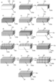
- Fig. 2 now shows in schematic representation variants of the Fig.1 shown joint sealing tape, each with a self-adhesive layer 24 arranged on the underside 20 and provided with a cover paper 22, in the form of a section a) according to the prior art, and then according to the invention b) with an aerogel-containing coating 26 on a long side 14 of the foam 12, c) with an aerogel-containing coating 28 on the top side 18 of the foam 12, d) with an aerogel-containing coating 30 on the underside 20 of the foam 12, namely between the foam 12 and the self-adhesive layer 24, e) with an aerogel-containing coating 28 on one long side 14 of the foam 12 and with an aerogel-containing coating 28 on the top side 18 of the foam 12, f) with an aerogel-containing coating 26, 32 on both long sides 14, 16 of the foam 12 and with an aerogel-containing coating 28 on the top side 18 of the foam 12 and g) with an aerogel-containing coating 26, 32 on both long sides 14, 16 of the foam 12 and with an
- Fig.3 shows a schematic representation of variants of the Fig.1 shown joint sealing tape, each with a self-adhesive layer 24 arranged on the underside 20 and provided with a cover paper 22, in the form of a cutout, namely according to the invention a) with aerogel distributed homogeneously in the foam 120, b) as a), but additionally with an aerogel-containing coating 26 on a long side 14 of the foam 120, c) as a), but additionally with an aerogel-containing coating 28 on the top side 18 of the foam 120, d) as a), but additionally with an aerogel-containing coating 30 on the underside 20 of the foam 120, namely between the foam 120 and the self-adhesive layer 24, e) as a), but additionally with an aerogel-containing coating 26 on a long side 14 of the foam 120 and with an aerogel-containing coating 28 on the top side 18 of the foam 120, f) as a), but additionally with an aerogel having a coating 26, 32 on both long sides 14, 16 of the
- Fig.4 shows a schematic representation of a pre-compressed second joint sealing tape 10, which is kept in stock in roll form, in a side view with an already unrolled, set-back section in a perspective view.
- the joint sealing tape 10 has two long sides 14, 16 and an upper side 18 which, when the joint sealing tape 10 is installed, adjoins one joint flank and an underside 20 which, when the joint sealing tape 10 is installed, adjoins the opposite joint flank.
- Two membrane layers 34 each run in the longitudinal direction between the upper side 18 and the underside 20 and parallel or almost parallel to the long sides 14, 16.
- the joint sealing tape 10 comprises three foams or foam elements 12a, 12b, 12c, with the two membrane layers 22 each being arranged between two foam elements 12a, 12b and 12b, 12c. This general structure of the joint sealing tape 10 is state of the art.
- Fig.5 shows a schematic representation of variants of the Fig.4 shown joint sealing tape 10, in the form of a section a) according to the prior art, b) with aerogel distributed homogeneously in an external foam element 120a, c) with aerogel distributed homogeneously in an internal foam element 120b, d) with aerogel distributed homogeneously in an external and an internal foam element 120a, 120b, e) as a), but with an aerogel-containing coating 26 on the long side 14 of an external foam element 12a, f) as b), but additionally with an aerogel-containing coating 26 on the long side 14 of the external aerogel-containing foam element 120a, g) as c), but additionally with an aerogel-containing coating 26 on a long side 14 of the external foam element 12a, h) as d) but additionally with an aerogel-containing coating 26 on the long side 14 of the external aerogel-containing foam element 120a, i) as in a), but additionally with an aerogel-containing coating 28 on the upper side 18 of
- Fig.6 shows in a purely schematic representation a section of a joint sealing tape, comprising a foam 12 with a self-adhesive layer 24 arranged on the underside 20 and provided with a cover paper 22, namely a) uncompressed, without aerogel, b) compressed, without aerogel, c) uncompressed with aerogel 36 homogeneously distributed in the foam 12 and d) compressed with aerogel 36 homogeneously distributed in the foam 12.
- Fig.6 explains the effect of an aerogel 36 homogeneously distributed in a foam 12 by impregnation.
- the Fig. 6 a) The foam 12 shown is uncompressed and has air-filled cavities or pores 38, which have an influence on the thermal conductivity of the foam 12.
- the air-filled cavities or pores 38 make the foam 12 thermally insulating.
- Fig. 6 b) shows the foam 12 from Fig. 6 a) in the compressed state. It can be clearly seen that the air has escaped from the previously existing cavities or pores 38 or that the cavities or pores 38 have disappeared, which disadvantageously increases the thermal conductivity of the compressed foam and the foam 12 is no longer thermally insulating.
- the foam 120 shown is homogeneously impregnated with an aerogel 36, wherein the aerogel 36 is arranged in the air-filled cavities or pores 38 of the foam 120.
- the aerogel 36 already leads to a reduction in the thermal conductivity in the uncompressed state of the foam 120 compared to a foam 12 which is also in the uncompressed state but not impregnated with aerogel, as is shown in Fig. 6a ).
- the aerogel 36 thus improves the thermal insulation of the foam 12.
- Fig. 6 d) shows the foam 120 from Fig. 6 c) in the compressed state. It is clearly visible that the aerogel 36 was not compressed. It was proven that the thermal conductivity of the compressed foam 120 containing the aerogel 36 has even further decreased compared to the thermal conductivity of the uncompressed foam 120 containing the aerogel 36. The thermal insulation of the foam 12 has therefore improved again.
Landscapes
- Engineering & Computer Science (AREA)
- Chemical & Material Sciences (AREA)
- Civil Engineering (AREA)
- Architecture (AREA)
- Structural Engineering (AREA)
- Health & Medical Sciences (AREA)
- Polymers & Plastics (AREA)
- Organic Chemistry (AREA)
- Medicinal Chemistry (AREA)
- Chemical Kinetics & Catalysis (AREA)
- Physics & Mathematics (AREA)
- Materials Engineering (AREA)
- Electromagnetism (AREA)
- Sealing Material Composition (AREA)
Description
- Die Erfindung betrifft ein Fugendichtungsband, das einen Schaumstoff aufweist.
- Komprimierbaren Fugendichtungsbänder, die einen Schaumstoff aufweisen, sind zum Abdichten insbesondere gegen Luftzug und Schlagregen beispielsweise aus der
DE 19641415 C2 , derDE 20009674 U1 oder derWO 2012/167762 A1 bekannt und werden in der Bautechnik zum Abdichten insbesondere von Bauteilen, beispielsweise von Fenster- und Türrahmen, gegenüber einem Mauerwerk, beispielsweise einer Gebäudewandöffnung, oder einer Bewegungsfuge in einer Fassade verwendet. Vorgenannte Fugendichtungsbänder weisen wenigstens eine Membranschicht auf. Weitere Fugendichtungsbänder, die keine Membranschicht aufweisen, sind beispielsweise aus derDE 1 000 946 A ,DE 40 20 230 A1 oder derDE 34 07 995 A1 bekannt.DE 20 2012 000883 U1 offenbart ein Fugendichtungsband umfassend einen Schaumstoff, wobei der Schaumstoff mit wenigstens einer Substanz ausgerüstet ist, wobei der Schaumstoff mit einer Imprägniermasse imprägniert ist. - Ein bekanntes Fugendichtungsband, das einen Schaumstoff umfasst, weist zwei Längsseiten sowie eine im Einbauzustand des Fugendichtungsbandes an die eine Fugenflanke, insbesondere eines Mauerwerks, angrenzende Oberseite und eine im Einbauzustand des Fugendichtungsbandes an die gegenüberliegende Fugenflanke, insbesondere des Bauteils, angrenzende Unterseite auf. Zwischen der Oberseite und Unterseite parallel bzw. nahezu parallel zu den Längsseiten können eine oder vorzugsweise mehrere Membranschichten jeweils in Längsrichtung verlaufen. Bekanntermaßen wird die Unterseite eines solchen Fugendichtungsbandes an dem abzudichtenden Bauteil, beispielsweise einem Fenster- und Türrahmen, angeklebt. Nach dem Einbau des Bauteils, beispielsweise in eine Gebäudewandöffnung, expandiert das zuvor komprimierte Fugendichtungsband, stellt sich also elastisch zurück, so dass die Oberseite des Fugendichtungsbandes am Mauerwerk der Gebäudewandöffnung angrenzt bzw. anliegt, und so das Bauteil am Mauerwerk der Gebäudewandöffnung abdichtet. Gattungsgemäße Fugendichtungsbänder werden zur Abdichtung auch in Fassadenfugen, insbesondere in Bestandsfugen, eingebracht.
- Ausgehend von diesem Stand der Technik liegt der Erfindung die grundsätzliche Aufgabe zugrunde, solche Fugendichtungsbänder, aber auch Bestandteile davon, derart weiterzuentwickeln, dass sie die an sie gestellten Anforderungen hinsichtlich der Schlagregendichtheit, der Dampfdiffusionsoffenheit, der Wärmedämmung, der Luftdichtheit und/oder des Brandschutzes besser erfüllen.
- Diese Aufgabe wird wenigstens teilweise mit einem Fugendichtungsband, das die in Anspruch 1 genannten Merkmale aufweist, gelöst. Weiterbildungen und vorteilhafte Ausgestaltungen der Erfindung ergeben sich aus der nachfolgenden Beschreibung sowie den Unteransprüchen.
- Erfindungsgemäß ist vorgesehen, dass der Schaumstoff mit wenigstens einer Substanz ausgerüstet ist, die die Wärmleitfähigkeit des Schaumstoffs oder die Wärmeleitfähigkeit des den Schaumstoff aufweisenden Fugendichtungsbandes herabsetzt.
- Eine Herabsetzung bzw. Verminderung der Wärmeleitfähigkeit bedeutet eine Verbesserung der Wärmedämmeigenschaften und so einen Wärmedämmeffekt. Die Wärmedämmung eines die wenigstens eine Substanz aufweisenden Schaumstoffs oder eines diesen aufweisenden Fugendichtungsbandes ist also besser als die Wärmedämmung eines die wenigstens eine Substanz nicht aufweisenden Schaumstoffs oder eines diesen nicht aufweisenden Fugendichtungsbandes. Die Anwendung eines die wenigstens eine Substanz aufweisenden Schaumstoffs oder eines diesen aufweisenden Fugendichtungsbandes in Fugen verbessert die Wärmeisolierung und vermeidet eine Wärmebrücke durch die Fuge.
- Bekannte Schaumstoffe oder Schaumstoff umfassende Fugendichtungsbänder, die die wenigstens eine Substanz nicht aufweisen, haben in der Regel im komprimierten Zustand aufgrund der Verkleinerung des innerhalb des Schaumstoffs vorhandenen Porenräume eine höhere Wärmeleitfähigkeit als im unkomprimierten Zustand. Schaumstoffe oder Schaumstoff aufweisende Fugendichtungsbänder, die im unkomprimierten Zustand möglicherweise noch eine ausreichend niedrige Wärmeleitfähigkeit aufweisen, haben diese im komprimierten Zustand nicht mehr. Im Einbauzustand des einen Schaumstoff aufweisenden Fugendichtungsbandes ist dieses üblicherweise nicht vollständig expandiert, so dass eine ausreichend niedrige Wärmeleitfähigkeit unter Umständen nicht gegeben ist. Die mit einem solchen Fugendichtungsband versehene Fuge, beispielsweise zwischen einem Fensterrahmen und einem Mauerwerk einer Gebäudewandöffnung, stellt eine Verschlechterung der Wärmeisolierung und damit eine unerwünschte Wärmebrücke dar. Erfindungsgemäße Schaumstoffe oder Schaumstoff umfassende Fugendichtungsbänder verbessern die Wärmeisolierung und vermeiden solche unerwünschten Wärmebrücken. Durch die Ausrüstung des Schaumstoffs mit wenigstens einer die Wärmeleitfähigkeit herabsetzenden Substanz wird eine ausreichend geringe Wärmeleitfähigkeit sowohl im unkomprimierten als auch im komprimierten Zustand, wie er im Einbauzustand des Fugendichtungsbandes üblich ist, erreicht.
- Erfindungsgemäße Schaumstoff umfassende Fugendichtungsbänder halten die Anforderung an den Mindestwärmeschutz im Bereich von Wärmebrücken gemäß dem Beiblatt 2 der DIN 4108-2:2013-2 "Wärmeschutz und Energie-Einsparung in Gebäuden - Teil 2: Mindestanforderungen an den Wärmeschutz" nicht nur ein, sondern unterschreiten diese.
- Es konnte darüber hinaus nachgewiesen werden, dass der erfindungsgemäße Schaumstoff oder das erfindungsgemäße Schaumstoff umfassende Fugendichtungsband im komprimierten Zustand eine geringere Wärmeleitfähigkeit aufweist als im unkomprimierten Zustand.
- Erfindungsgemäße Schaumstoff umfassende Fugendichtungsbänder ermöglichen somit eine hochwertige Wärmedämmung, gerade im Zusammenspiel mit beispielsweise einem Fensterrahmen, der eine niedrige Wärmeleitfähigkeit aufweist, und einer gedämmten Gebäudewand.
- Vorzugsweise wird unter dem Begriff "Ausrüsten" nicht die Zugabe der wenigstens einen Substanz zu den Ausgangsmaterialien zur Herstellung des Schaumstoffs verstanden, sondern das Versehen eines bereits hergestellten Schaumstoffs mit der wenigstens einen Substanz.
- Erfindungsgemäß ist Schaumstoff mit einer Imprägniermasse imprägniert, wobei die Imprägniermasse die wenigstens eine Substanz enthält.
- Verfahren zum Imprägnieren eines Schaumstoffs mit einer Imprägniermasse sind dem Fachmann bekannt. Üblicherweise dient die Imprägnierung dazu, den Schaumstoff oder das Schaumstoff umfassende Fugendichtungsband mit einem verzögerten Rückstellverhalten auszubilden. Darüber hinaus kann der Schaumstoff oder das den Schaumstoff aufweisende Fugendichtungsband durch das Imprägnieren mit einer Imprägniermasse mit weiteren Funktionalitäten, insbesondere einer wasserabweisenden Wirkung, einer Luftdichtheit, einem Flammschutz, einer Farbe oder einem UV-Schutz, ausgerüstet werden.
- Bei der Imprägniermasse handelt es sich vorzugsweise um eine Lösung oder Dispersion der wenigstens einen Substanz. Diese Lösung oder Dispersion kann zusätzlich zu der wenigstens einen Substanz auch bekannte Füllstoffe und/oder Hilfsstoffe, beispielsweise Schichtsilikate, Tonmineralien, Metalloxide, Metallhydroxide, Glaskugeln, thermoexpandierbare Substanzen, Ruß, Farbpigmente, Flammschutzmittel, Hydrophobierungsmittel und dergleichen, enthalten.
- Es kann vorteilhaft sein, wenn die Imprägniermasse ein Bindemittel, vorzugsweise eine wässrige Dispersion auf Basis eines Acrylsäureesters, besonders bevorzugt eine wässrige Dispersion eines Polyacrylsäurebutylesters umfasst.
- Für einige Anwendungen kann es auch vorteilhaft sein, wenn die Imprägniermasse ein Bindemittel auf Polyurethanbasis umfasst.
- Für gewisse Anwendungen kann es auch vorteilhaft sein, wenn die Imprägniermasse ein Bindemittel auf Wachsbasis umfasst.
- Für bestimmte Anwendungen kann es auch vorteilhaft sein, wenn die Imprägniermasse ein Bindemittel auf Bitumenbasis umfasst.
- Durch das Imprägnieren wird das Raumgewicht des imprägnierten Schaumstoffs nach seiner Trocknung im Vergleich zu einem nicht imprägnierten Schaumstoff erhöht.
- Üblicherweise wird der Schaumstoff mit einer Imprägniermasse getränkt, indem der Schaumstoff in die Imprägniermasse eingetaucht wird, so dass die Imprägniermasse, bevorzugt mit Hilfe von Tauch- oder Quetschwalzen, in die Poren des Schaumstoffs eindringt und diesen vollständig durchdringt. Die Imprägniermasse füllt also die Poren des Schaumstoffs aus. Vorzugsweise wird hierzu ein offenporiger Schaumstoff verwendet.
- Nach dem Imprägnieren wird der Schaumstoff mittels mindestens einer Walze, insbesondere mit einem Walzenpaar, gewalzt. Mittels der wenigstens einen Walze wird ein Teil der Imprägniermasse aus dem Schaumstoffkörper bis zum gewünschten Imprägnierungsgrad aus- bzw. abgequetscht. Durch Variation des Walzendruckes kann der Imprägnierungsgrad, das heißt die Menge der vom Schaumstoff aufgenommenen wenigstens einen Substanz, variiert werden. Anschließend wird der Schaumstoff getrocknet und geschnitten.
- Es kann vorteilhaft sein, wenn der Schaumstoff zusätzlich zur Imprägnierung mit der wenigstens einen Substanz ein- oder mehrseitig beschichtet ist.
- Ist eine hohe Konzentration der wenigstens einen Substanz im Schaumstoff erwünscht, kann es vorteilhaft sein, wenn der Schaumstoff zusätzlich zur Imprägnierung mit der wenigstens einen Substanz ein- oder mehrseitig beschichtet ist.
- Durch die Imprägnierung und/oder Beschichtung ist es möglich, große Mengen der wenigstens einen Substanz in und/oder auf den Schaumstoff zu bringen.
- Es ist auch möglich, den Schaumstoff unter Druck bzw. im Vakuum oder mit Hilfe einer Sprüheinrichtung zu imprägnieren bzw. zu beschichten.
- Die Konzentration der wenigstens einen Substanz im Schaumstoff kann auch durch die Konzentration der wenigstens einen Substanz in der Imprägniermasse beeinflusst werden.
- Durch Kombination der vorgenannten Parameter "Konzentration der wenigstens einen Substanz in der Imprägniermasse", "Walzenspalt beim Abquetschen" und gegebenenfalls "zusätzliche Beschichtung" kann das Verhältnis Schaumstoff, Bindemittel, weitere Füllstoffe und/oder Hilfsstoffe zu der wenigstens einen Substanz eingestellt werden.
- Es kann vorteilhaft sein, wenn ein erfindungsgemäß imprägnierter Schaumstoff eine Selbstklebeschicht aufweist. Es kann vorteilhaft sein, wenn ein erfindungsgemäß imprägnierter Schaumstoff eine Schwerschichtfolie aufweist. Es kann vorteilhaft sein, wenn ein erfindungsgemäß imprägnierter Schaumstoff eine zusätzliche Beschichtung beispielsweise in Form einer Aluminium- und/oder einer Polyurethanfolie aufweist. Hierdurch kann eine Verbesserung der schall- und/oder wärmetechnischen Isolierung von Rolllädenkästen erreicht werden.
- Es kann vorteilhaft sein, wenn der Schaumstoff derart mit der wenigstens einen Substanz ausgerüstet ist, dass die Wärmeleitfähigkeit des Schaumstoffs oder des Schaumstoff umfassenden Fugendichtungsbandes in einem unkomprimierten Zustand ≤ 0,040 W/mK, vorzugsweise ≤ 0,039 W/mK, besonders bevorzugt ≤ 0,038 W/mK, ganz besonders bevorzugt ≤ 0,037 W/mK, noch bevorzugter ≤ 0,0366 W/mK beträgt.
- Die Wärmeleitfähigkeit - ausgedrückt durch die Wärmeleitzahl (λ) in Watt pro Meter mal Kelvin (W/mK) beschreibt das Vermögen eines Materials, thermische Energie mittels Wärmeleitung zu transportieren. Die Wärmeleitfähigkeit wird gemäß DIN EN 12667 bei einer Mitteltemperatur von 10 °C bestimmt.
- Es kann vorteilhaft sein, wenn der Schaumstoff derart mit der Substanz ausgerüstet ist, dass die Wärmeleitfähigkeit des Schaumstoffs oder des Schaumstoff umfassenden Fugendichtungsbandes in einem komprimierten Zustand ≤ 0,04 W/mK, vorzugsweise ≤ 0,039 W/mK, besonders bevorzugt ≤ 0,038 W/mK, ganz besonders bevorzugt ≤ 0,037 W/mK, noch bevorzugter ≤ 0,0366 W/mK beträgt.
- Es kann vorteilhaft sein, wenn der Schaumstoff derart mit der wenigstens einen Substanz ausgerüstet ist, dass die Wärmeleitfähigkeit des Schaumstoffs oder des Schaumstoff umfassende Fugendichtungsbandes in einem komprimierten Zustand geringer ist als in einem unkomprimierten Zustand.
- Es kann vorteilhaft sein, wenn der Schaumstoff derart mit der wenigstens einen Substanz ausgerüstet ist, dass die Differenz zwischen der Wärmeleitfähigkeit des Schaumstoffs oder des Schaumstoff umfassenden Fugendichtungsbandes in einem unkomprimierten Zustand und in einem um 36%, vorzugsweise um 50 %, besonders bevorzugt um >50% der ursprünglichen Höhe komprimierten Zustand ≥ 0,0005 W/mK, vorzugsweise ≥ 0,0008 W/mK, besonders bevorzugt ≥ 0,001 W/mK, beträgt.
- Es kann vorteilhaft sein, wenn es sich bei der wenigstens einen Substanz um einen Feststoff handelt. Ein solcher lässt sich üblicherweise gut handhaben und ist in der Anwendung selbst im Wesentlichen nicht komprimierbar.
- Es kann vorteilhaft sein, wenn die wenigstens eine Substanz eine Wärmeleitfähigkeit von < 0,04 W/mK, vorzugsweise ≤ 0,035 W/mK, besonders bevorzugt ≤ 0,035 W/mK, ganz besonders bevorzugt ≤ 0,030 W/mK, noch bevorzugter ≤ 0,025 W/mK, noch bevorzugter ≤ 0,020 W/mK, noch bevorzugter ≤ 0,019 W/mK, noch bevorzugter ≤ 0,018 W/mK, noch bevorzugter ≤ 0,017 W/mK, noch bevorzugter ≤ 0,016 W/mK, noch bevorzugter ≤ 0,015 W/mK aufweist.
- Diese außerordentlich geringe Wärmeleitfähigkeit bewirkt eine hohe Temperaturstabilität der Substanz, somit des Schaumstoffs sowie eines diesen Schaumstoff umfassenden Fugendichtungsbandes.
- Es kann vorteilhaft sein, wenn die Substanz derart stabil ausgebildet ist, dass diese bei einem Komprimieren des Schaumstoffs oder des Schaumstoffs umfassenden Fugendichtungsbandes nicht komprimiert wird.
- Es kann vorteilhaft sein, wenn die mittlere Partikelgröße d50 der Substanz weniger als 500 µm, vorzugsweise weniger als 100 µm, besonders bevorzugt zwischen 5 und 20 µm, ganz besonders bevorzugt weniger als 10 µm, noch bevorzugter weniger als 5 µm, beträgt. Methoden zur Bestimmung der mittleren Partikelgröße d50 sind dem Fachmann bekannt. Die mittlere Partikelgröße kann durch Erstellung einer Partikelgrößenverteilung ermittelt werden. Die Messung kann hierbei mittels Lichtstreuung, insbesondere mittels Laserdiffraktometrie oder Photonenkorrelationsspektroskopie, erfolgen.
- Erfindungsgemäß handelt es sich bei der Substanz um ein Aerogel.
- Aerogele sind hochporöse Festkörper, bei denen der überwiegende Teil des Volumens aus Poren besteht.
- Es kann vorteilhaft sein, wenn die Aerogele auf Silikat-Basis basieren. Es kann für einige Einsatzfälle aber auch vorteilhaft sein, wenn die Aerogele auf Kunststoff-Basis. Für gewisse Einsatzfälle kann es aber auch vorteilhaft sein, wenn die Aerogele auf Kohlenstoff-Basis basieren.
- Die Poren der Aerogele weisen einen Durchmesser auf, der im Nanometer-Bereich liegt.
- Infolge des großen Porenvolumens eignen sich die Aerogele erfindungsgemäß zur Herabsetzung der Wärmeleitfähigkeit des Schaumstoffs bzw. des den Schaumstoff aufweisenden Fugendichtungsbandes bei geringer Dichte.
- Die Aerogele liegen als Partikel vor und können erfindungsgemäß in einer Imprägniermasse dispergiert werden.
- Aerogele, vorzugsweise Silicat-Aerogele, sind vorteilhaft chemisch inert.
- Es kann vorteilhaft sein, wenn die Aerogele anorganisch sind. Es kann aber auch vorteilhaft sein, wenn die Aerogele anorganisch-organisch sind. Es kann aber auch vorteilhaft sein, wenn die Aerogele organisch sind.
- Bevorzugt werden Aerogele, die Si-Verbindungen enthalten. Besonders bevorzugt sind SiO2-Aerogele, die gegebenenfalls organisch modifiziert sind.
- Die Aerogel-Partikel können erfindungsgemäß in monomodaler, bimodaler oder multimodaler Verteilung eingesetzt werden.
- In einer bevorzugten Ausführungsform weisen die Aerogel-Partikel eine hydrophobe Beschichtung, insbesondere hydrophobe Oberflächengruppen, auf.
- Bevorzugt ist das Ausmaß der Hydrophobierung hinreichend hoch zu bemessen, um dauerhaft ein Eindringen von Wasser in das Innere der Aerogelpartikel zu verhindern. Gleichzeitig wird ein möglichst geringer Anteil an organischem Material der modifizierten Partikel angestrebt, um die Brennbarkeit der Partikel zu minimieren.
- Für einige Anwendungen kann es vorteilhaft sein, wenn es sich bei der wenigstens einen Substanz um pyrogene Kieselsäure, vorzugsweise mit hydrophober Oberfläche, handelt.
- Es kann vorteilhaft sein, wenn die Substanz derart dimensioniert ist, dass diese auf den Schaumstoff und/oder vorzugsweise in die Poren des Schaumstoffs, insbesondere des Fugendichtungsbandes, bringbar ist.
- Es kann vorteilhaft sein, wenn die wenigstens eine Substanz im und auf dem Schaumstoff des Fugendichtungsbandes, homogen verteilt ist. Es kann für einige Anwendungsfälle aber auch vorteilhaft sein, wenn die wenigstens eine Substanz im und auf dem Schaumstoff, beispielsweise über die Breite und/oder über die Höhe des Fugendichtungsbandes, inhomogen verteilt ist.
- Es kann vorteilhaft sein, wenn die Imprägniermasse die Substanz in einer Menge von 1 bis 5 Gew.-% i.Tr., vorzugsweise von 2 bis 3 Gew.-% i.Tr., jeweils bezogen auf 100 Gew.-% i.Tr. Imprägniermasse enthält.
- Es hat sich auch gezeigt, dass aufgrund der Ausrüstung des Schaumstoffs mit einer die Wärmeleitfähigkeit des Schaumstoffs oder des Schaumstoff umfassenden Fugendichtungsbandes herabsetzenden Substanz, insbesondere mit einer wenigstens einer der vorgenannten Substanzen, eine erhebliche Verbesserung des Flammschutzes erreicht wird.
- Es kann von Vorteil sein, wenn die eingesetzte Art und Menge der wenigstens einen Substanz derart gewählt ist, dass das Schaumstoff umfassende Fugendichtungsband in seinem angegebenen Anwendungsbereich wenigstens einer der gängigen Brandnormen für den Baubereich entspricht, beispielsweise DIN 4102-B1 und/oder DIN 4102-B2 und/oder DIN 4102-≥F30 und/oder EN13501 Klasse E bis B und/oder EN 13501>R30 bzw. >EI30.
- Bei einem Funktionserhaltungstest nach einer der vorgenannten Normen erfolgt die Beflammung und damit Erhitzung eines Fugendichtungsbandes gemäß der so genannten Einheitstemperaturkurve (ETK).
- Durch die im Anwendungsbereich des erfindungsgemäßen Gegenstandes herabgesetzte und damit verbesserte Wärmeleitfähigkeit der Fugenabdichtung, die zu einer besseren thermischen Isolierung von Brandschutzbauteilen beiträgt, wird die Hitzeübertragung im Brandfall bzw. im Versuchsfall mit Belastungen nach der Einheitstemperaturkurve vorteilhaft reduziert.
- Die gilt beispielsweise bei Anschlüssen von Brandschutztüren mit der Klassifizierung "I" nach der EN 1634.
- Nach alledem führt die Ausrüstung eines Schaumstoffs eines Fugendichtungsbandes, mit wenigstens einer die Wärmeleitfähigkeit des Schaumstoffs eines Fugendichtungsbandes, herabsetzenden Substanz, mit einem Aerogel, zu einer Verbesserung der Wärmeleitfähigkeit, zu einer Verbesserung des Flammschutz, zu einer Verbesserung der Hydrophobierung und/oder zu einer Verbesserung Luftdichtheit des Schaumstoffs oder des den Schaumstoff enthaltenden Fugendichtungsbandes.
- Es kann vorteilhaft sein, wenn der Schaumstoff offenzellig oder zumindest teilweise offenzellig ist.
- Es kann vorteilhaft sein, wenn der Schaumstoff, insbesondere für ein Fugendichtungsband, ein Polyurethanschaumstoff ist.
- Es kann vorteilhaft sein, wenn der Schaumstoff rückstellfähig ist.
- Es kann vorteilhaft sein, wenn der Schaumstoff nach einer Imprägnierung verzögert rückstellfähig ist.
- Es kann vorteilhaft sein, wenn der Schaumstoff ein retikulierter Polyurethanschaumstoff ist.
- Es kann vorteilhaft sein, wenn der Schaumstoff, insbesondere für eine Rollladenkastendämmung, ein Melaminharzschaumstoff ist.
- Es kann vorteilhaft sein, wenn wenigstens ein Schaumstoff, Schaumstoffabschnitt oder Schaumstoffelement eines Fugendichtungsbandes, wie es Gegenstand der
WO 2012/167762 A1 ist, erfindungsgemäß mit der wenigstens einen Substanz ausgerüstet ist. - Es kann vorteilhaft sein, wenn wenigstens ein Schaumstoff, Schaumstoffabschnitt oder Schaumstoffelement eines Fugendichtungsbandes, wie es Gegenstand der
DE 196 41 415 A1 oder derDE 200 09 674 U1 ist, erfindungsgemäß mit der wenigstens einen Substanz ausgerüstet ist. - Es kann vorteilhaft sein, wenn wenigstens ein Schaumstoff, Schaumstoffabschnitt oder Zusatz-Schaumstoffmaterial bzw. Schaumstoffstreifen eines Fugendichtungsbandes, wie es Gegenstand der
EP 1 811 111 A2 ist, erfindungsgemäß mit der wenigstens einen Substanz ausgerüstet ist. Es kann insbesondere von Vorteil sein, wenn wenigstens eine der inEP 1 811 111 A2 genannten Seiten, insbesondere wenigstens Schmalseite, eines Fugendichtungsbandes mit der wenigstens einen Substanz beschichtet ist. - Es kann vorteilhaft sein, wenn wenigstens ein Schaumstoff, Schaumstoffabschnitt oder Schaumstoffelement eines profilierten Fugendichtungsbandes, wie es Gegenstand der
WO 2009/138311 A1 ist, erfindungsgemäß mit der wenigstens einen Substanz ausgerüstet ist. - Es kann vorteilhaft sein, wenn wenigstens ein Schaumstoff, Schaumstoffabschnitt oder Schaumstoffelement eines Fugendichtungsbandes, wie es Gegenstand der
EP 2 112 292 A2 ist, erfindungsgemäß mit der wenigstens einen Substanz ausgerüstet ist. - Es kann vorteilhaft sein, wenn wenigstens ein Schaumstoff, Schaumstoffabschnitt oder Schaumstoffelement eines Fugendichtungsbandes, wie es Gegenstand der
EP 2 784 231 A1 ist, erfindungsgemäß mit der wenigstens einen Substanz ausgerüstet ist. - Es kann vorteilhaft sein, wenn wenigstens ein Schaumstoff, Schaumstoffabschnitt oder Schaumstoffelement eines Fugendichtungsbandes, wie es Gegenstand der
EP 2 420 631 A2 ist, erfindungsgemäß mit der wenigstens einen Substanz ausgerüstet ist. Es kann insbesondere von Vorteil sein, wenn das in derEP 1 811 111 A2 genannte Einlegeteil mit der wenigstens einen Substanz ausgerüstet ist. - Es kann vorteilhaft sein, wenn wenigstens ein Schaumstoff, Schaumstoffabschnitt oder Schaumstoffelement eines Fugendichtungsbandes, wie es Gegenstand der
EP 2 354 410 A2 ist, erfindungsgemäß mit der wenigstens einen Substanz ausgerüstet ist. Es kann insbesondere von Vorteil sein, wenn wenigstens ein der in derEP 2 354 410 A2 genannten Schaumstoffstreifen mit der wenigstens einen Substanz ausgerüstet ist. - Es kann vorteilhaft sein, wenn wenigstens ein Schaumstoff, Schaumstoffabschnitt oder Schaumstoffelement eines Fugendichtungsbandes, wie es Gegenstand der
EP 2 065 548 A2 ist, erfindungsgemäß mit der wenigstens einen Substanz ausgerüstet ist. Es kann insbesondere von Vorteil sein, wenn wenigstens ein der in derEP 2 065 548 A2 genannten Schaumstoffstreifen mit der wenigstens einen Substanz ausgerüstet ist. - Es kann vorteilhaft sein, wenn wenigstens ein Schaumstoff, Schaumstoffabschnitt oder Schaumstoffelement eines Fugendichtungsbandes, wie es Gegenstand der
WO 94/20701 A1 WO 94/20701 A1 - Es kann vorteilhaft sein, wenn wenigstens ein Schaumstoff, Schaumstoffabschnitt oder Schaumstoffelement eines Fugendichtungsbandes, wie es Gegenstand der
EP 2 982 821 A1 ist, erfindungsgemäß mit der wenigstens einen Substanz ausgerüstet ist. Es kann insbesondere von Vorteil sein, wenn der in derEP 2 982 821 A1 genannte Schaumstoffkörper entsprechend ungleichmäßig mit der wenigstens einen Substanz ausgerüstet ist. - Es kann vorteilhaft sein, wenn wenigstens ein Schaumstoff, Schaumstoffabschnitt oder Schaumstoffelement eines Fugendichtungsbandes, wie es Gegenstand der
EP 2 107 176 A1 ist, erfindungsgemäß mit der wenigstens einen Substanz ausgerüstet ist. Es kann insbesondere von Vorteil sein, wenn eine in derEP 2 107 176 A1 auf mindestens einer Seitenfläche der Dichtbandrolle vorgesehene Beschichtung mit der wenigstens einen Substanz ausgerüstet ist. - Es kann vorteilhaft sein, wenn wenigstens ein Schaumstoff, Schaumstoffabschnitt oder Schaumstoffelement eines Fugendichtungsbandes, wie es Gegenstand der
EP 2 415 942 A1 ist, erfindungsgemäß mit der wenigstens einen Substanz ausgerüstet ist. Es kann insbesondere von Vorteil sein, wenn wenigstens einer der in derEP 2 415 942 A1 genannten Schaumstoffstreifen mit der wenigstens einen Substanz ausgerüstet ist. - Es kann vorteilhaft sein, wenn wenigstens ein Schaumstoff, Schaumstoffabschnitt oder Schaumstoffelement eines Fugendichtungsbandes, wie es Gegenstand der
EP 2 990 575 A1 ist, erfindungsgemäß mit der wenigstens einen Substanz ausgerüstet ist. Es kann insbesondere von Vorteil sein, wenn wenigstens einer der in derEP 2 990 575 A1 genannten Schaumstoffstreifen mit der wenigstens einen Substanz ausgerüstet ist. - Vorzugsweise weist das Fugendichtungsband zwei Längsseiten sowie eine im Einbauzustand des Fugendichtungsbandes an die eine Fugenflanke angrenzende Ober- und eine im Einbauzustand des Fugendichtungsbandes an die gegenüberliegende Fugenflanke angrenzende Unterseite aufweist. Die Breite des Fugendichtungsbandes ist somit der Abstand zwischen zwei Längsseiten.
- Der Schaumstoff eines Fugendichtungsbandes kann in mehrere Schaumstoffabschnitte oder Schaumstoffelemente unterteilt sein. Die Unterteilung kann sich beispielsweise durch wenigstens eine im Schaumstoff vorhandene Trennschicht, beispielsweise in Form einer Klebstoff- oder Membranschicht, oder durch ein unterschiedliches Höhenprofil ergeben. Es kann vorteilhaft sein, wenn ein oder mehr als ein Schaumstoffabschnitt oder Schaumstoffelement mit der wenigstens einen Substanz ausgerüstet ist. Bei mehreren Schaumstoffabschnitten oder Schaumstoffelementen kann es vorteilhaft sein, wenn wenigstens zwei Schaumstoffabschnitte oder Schaumstoffelemente mit der wenigstens einen Substanz entweder in gleicher oder in unterschiedlicher Konzentration ausgerüstet sind.
- Es kann vorteilhaft sein, wenn mehrere Dichtbereiche innerhalb eines Fugendichtungsbandes vorgesehen sind.
- Es kann vorteilhaft sein, wenn wenigstens zwei Schaumstoffabschnitte unterschiedliche Raumgewichte aufweisen.
- Es kann zweckmäßig sein, wenn der Schaumstoff bzw. wenigstens ein oder jeder Schaumstoffabschnitt ein Polyurethan-Schaumstoff, vorzugsweise ein Polyurethan-Weichschaumstoff ist. Dieser stellt sich nach einer Vorkomprimierung besonders gut innerhalb der Fuge zurück und sorgt für eine dauerhafte Abdichtung.
- Es kann vorteilhaft sein, wenn der Schaumstoff bzw. wenigstens ein oder jeder Schaumstoffabschnitt oder ein oder jedes Schaumstoffelement ein oder mehrere Funktionsbereiche aufweist, vorzugsweise einen ersten nach außen schlagregendichten Bereich, einen zweiten wärmedämmenden sowie schallmindernden Bereich und einen dritten nach innen luftdichten Bereich.
- Es kann vorteilhaft sein, wenn nur der wärmedämmende Bereich die wenigstens eine Substanz aufweist.
- Es kann aber auch von Vorteil sein, wenn der zweite und dritte Bereich die wenigstens eine Substanz aufweist.
- Es kann vorteilhaft sein, wenn die nach innen weisende Längsseite zusätzlich oder ausschließlich mit der wenigstens einen Substanz beschichtet ist.
- Es kann vorteilhaft sein, wenn die Ober- oder/und Unterseite zusätzlich oder ausschließlich mit der wenigstens einen Substanz beschichtet ist.
- Es kann zweckmäßig sein, wenn das Fugendichtungsband komprimierbar, vorzugsweise vorkomprimiert ist.
- Vorteilhaft kann das Fugendichtungsband in Rollenform vorkomprimiert und verzögert rückstellfähig sein.
- Vorzugsweise beträgt die Dicke des Fugendichtungsbandes im nicht komprimierten Zustand zwischen 10 mm und 100 mm, vorzugsweise zwischen 18 mm bis 60 mm.
- Es kann vorteilhaft sein, wenn das Fugendichtungsband zur Abdichtung von Fugen zwischen zusammengefügten Bauelementen im Hausbau, insbesondere zwischen Wandöffnungen einer Außenwand und Fenster- oder Türrahmen, vorzugsweise ohne Zuhilfenahme zusätzlicher Fugenbändern oder Hinterfüllmaterialien, einsetzbar ist.
- Es kann vorteilhaft sein, wenn das Fugendichtungsband zur Abdichtung von Fugen in einem Wärmedämmverbundsystem einsetzbar ist.
- Es kann vorteilhaft sein, wenn das Fugendichtungsband zur Abdichtung von Fugen in einem an einer Vorwandmontagezarge einsetzbar ist.
- Es kann von Vorteil sein, wenn das Fugendichtungsband einseitig selbstklebend ausgebildet ist. Die Seite kann vollflächig mit einer Selbstklebeschicht oder nicht vollflächig mit einer oder mehr als einer Selbstklebebahn beschichtet sein, welche vorzugsweise mit einem lösbaren Silikonpapier abgedeckt ist.
- Es wurde die Wärmeleitfähigkeit gemäß DIN EN 12667 bei einer Mitteltemperatur von 10 °C an vier Proben, die eine Dicke von 30 mm hatten, bestimmt.
- Schaumstoff (imprägniert ohne Substanz unkomprimiert): 0,0425 W/mK
- Schaumstoff (imprägniert ohne Substanz, um 36% komprimiert): 0,0433 W/mK
- Schaumstoff (imprägniert mit Aerogel, unkomprimiert): 0,0366 W/mK
- Schaumstoff (imprägniert mit Aerogel, um 36% komprimiert): 0,0361 W/mK
- Das Beispiel zeigt deutlich, dass der die wenigstens eine Substanz nicht aufweisende Schaumstoff im komprimierten Zustand eine höhere Wärmeleitfähigkeit hat als im unkomprimierten Zustand. Die im unkomprimierten Zustand des Schaumstoffs hohe Wärmeleitfähigkeit erhöht sich nachteilig im komprimierten Zustand.
- Durch die Ausrüstung des Schaumstoffs mit einem die Wärmeleitfähigkeit herabsetzenden Aerogel wird eine ausreichend geringe Wärmeleitfähigkeit nicht nur im unkomprimierten, sondern auch im komprimierten Zustand erreicht, wobei die Wärmleitfähigkeit im komprimierten Zustand vorteilhaft sogar geringer ist als im unkomprimierten.
- Weitere vorteilhafte Ausgestaltungen der Erfindung ergeben sich aus der Zeichnung in Zusammenhang mit deren Beschreibung, wobei nachfolgend die Erfindung anhand von Ausführungsbeispielen erläutert wird, die in der Zeichnung dargestellt sind. In dieser zeigen:
- Fig. 1
- eine schematische Darstellung eines in Rollenform vorrätig gehaltenen und vorkomprimierten ersten Fugendichtungsbandes in Seitenansicht mit einem bereits abgerollten, zurückgestellten Abschnitt in perspektivischer Ansicht, wobei das Fugendichtungsband einen Schaumstoff aufweist,
- Fig. 2
- in schematischer Darstellung Varianten des in
Fig. 1 gezeigten Fugendichtungsbandes, jeweils mit einer auf der Unterseite angeordneten und mit einem Abdeckpapier versehenen Selbstklebeschicht, in Form eines Abschnitts a) gemäß Stand der Technik, b) mit einer Aerogel aufweisenden Beschichtung auf einer Längsseite des Schaumstoffs, c) mit einer Aerogel aufweisenden Beschichtung auf der Oberseite des Schaumstoffs, d) mit einer Aerogel aufweisenden Beschichtung auf der Unterseite des Schaumstoffs, zwischen Schaumstoff und Selbstklebeschicht, e) mit einer Aerogel aufweisenden Beschichtung auf einer Längsseite des Schaumstoffs und mit einer Aerogel aufweisenden Beschichtung auf der Oberseite des Schaumstoffs, f) mit einer Aerogel aufweisenden Beschichtung auf beiden Längsseiten des Schaumstoffs und mit einer Aerogel aufweisenden Beschichtung auf der Oberseite des Schaumstoffs und g) mit einer Aerogel aufweisenden Beschichtung auf beiden Längsseiten des Schaumstoffs sowie mit einer Aerogel aufweisenden Beschichtung auf der Oberseite des Schaumstoffs und mit einer Aerogel aufweisenden Beschichtung auf der Unterseite des Schaumstoffs, zwischen Schaumstoff und Selbstklebeschicht, - Fig. 3
- in schematischer Darstellung Varianten des in
Fig. 1 gezeigten Fugendichtungsbandes, jeweils mit einer auf der Unterseite angeordneten und mit einem Abdeckpapier versehenen Selbstklebeschicht, in Form eines Abschnitts a) mit homogen im Schaumstoff verteiltem Aerogel, b) wie a), aber zusätzlich mit einer Aerogel aufweisenden Beschichtung auf einer Längsseite des Schaumstoffs, c) wie a), aber zusätzlich mit einer Aerogel aufweisenden Beschichtung auf der Oberseite des Schaumstoffs, d) wie a), aber zusätzlich mit einer Aerogel aufweisenden Beschichtung auf der Unterseite des Schaumstoffs, zwischen Schaumstoff und Selbstklebeschicht, e) wie a), aber zusätzlich mit einer Aerogel aufweisenden Beschichtung auf einer Längsseite des Schaumstoffs und mit einer Aerogel aufweisenden Beschichtung auf der Oberseite des Schaumstoffs, f) wie a), aber zusätzlich mit einer Aerogel aufweisenden Beschichtung auf beiden Längsseiten des Schaumstoffs und mit einer Aerogel aufweisenden Beschichtung auf der Oberseite des Schaumstoffs und g) wie a), aber zusätzlich mit einer Aerogel aufweisenden Beschichtung auf beiden Längsseiten des Schaumstoffs sowie mit einer Aerogel aufweisenden Beschichtung auf der Oberseite des Schaumstoffs und mit einer Aerogel aufweisenden Beschichtung auf der Unterseite des Schaumstoffs, zwischen Schaumstoff und Selbstklebeschicht, - Fig. 4
- eine schematische Darstellung eines in Rollenform vorrätig gehaltenen und vorkomprimierten zweiten Fugendichtungsbandes in Seitenansicht mit einem bereits abgerollten, zurückgestellten Abschnitt in perspektivischer Ansicht, wobei das Fugendichtungsband drei Schaumstoffelemente aufweist,
- Fig. 5
- in schematischer Darstellung Varianten des in
Fig. 4 gezeigten Fugendichtungsbandes, in Form eines Abschnitts a) gemäß Stand der Technik, b) mit homogen in einem außenliegenden Schaumstoffelement verteiltem Aerogel, c) mit homogen in einem innenliegenden Schaumstoffelement verteiltem Aerogel, d) mit homogen in einem außen- und in einem innenliegenden Schaumstoffelement verteiltem Aerogel, e) wie a), aber mit einer Aerogel aufweisenden Beschichtung auf der Längsseite eines außenliegenden Schaumstoffelements, f) wie b), aber zusätzlich mit einer Aerogel aufweisenden Beschichtung auf der Längsseite des außenliegenden Aerogel aufweisenden Schaumstoffelements, g) wie c), aber zusätzlich mit einer Aerogel aufweisenden Beschichtung auf einer Längsseite des außenliegenden Schaumstoffelements, h) wie d) aber zusätzlich mit einer Aerogel aufweisenden Beschichtung auf der Längsseite des außenliegenden Aerogel aufweisenden Schaumstoffelements, i) wie a), aber zusätzlich mit einer Aerogel aufweisenden Beschichtung auf der Oberseite der Schaumstoffelemente, j) wie b), aber zusätzlich mit einer Aerogel aufweisenden Beschichtung auf der Oberseite der Schaumstoffelemente, k) wie c) aber zusätzlich mit einer Aerogel aufweisenden Beschichtung auf der Oberseite der Schaumstoffelemente, l) wie d), aber zusätzlich mit einer Aerogel aufweisenden Beschichtung auf der Oberseite der Schaumstoffelemente, m) wie e), aber zusätzlich mit einer Aerogel aufweisenden Beschichtung auf der Oberseite der Schaumstoffelemente, n) wie f), aber zusätzlich mit einer Aerogel aufweisenden Beschichtung auf der Oberseite der Schaumstoffelemente, o) wie g) aber zusätzlich mit einer Aerogel aufweisenden Beschichtung auf der Oberseite der Schaumstoffelemente, p) wie h), aber zusätzlich mit einer Aerogel aufweisenden Beschichtung auf der Oberseite der Schaumstoffelemente und - Fig. 6
- in rein schematischer Darstellung jeweils einen Ausschnitt eines Fugendichtungsbandes, umfassend einen Schaumstoff mit einer auf der Unterseite angeordneten und mit einem Abdeckpapier versehenen Selbstklebeschicht, nämlich a) unkomprimiert, ohne Aerogel, b) komprimiert, ohne Aerogel, c) unkomprimiert mit homogen im Schaumstoff verteiltem Aerogel und d) komprimiert mit homogen im Schaumstoff verteiltem Aerogel.
- In der Zeichnung sind die für das Verständnis der Erfindung wesentlichen Merkmale dargestellt und erläutert. Werden in den Figuren gleiche Bezugsziffern verwendet, so bezeichnen diese gleiche Teile.
-
Fig. 1 zeigt eine schematische Darstellung eines in Rollenform vorrätig gehaltenen und vorkomprimierten ersten Fugendichtungsbandes 10 in Seitenansicht mit einem bereits abgerollten, zurückgestellten Abschnitt in perspektivischer Ansicht, wobei das Fugendichtungsband 10 einen Schaumstoff 12 aufweist. Das Fugendichtungsband 10 weist zwei Längsseiten 14, 16 sowie eine im Einbauzustand des Fugendichtungsbandes 10 an die eine Fugenflanke angrenzende Oberseite 18 und eine im Einbauzustand des Fugendichtungsbandes 10 an die gegenüberliegende Fugenflanke angrenzende Unterseite 20 auf. Dieser allgemeine Aufbau des Fugendichtbandes 10 ist Stand der Technik. -
Fig. 2 zeigt nun in schematischer Darstellung Varianten des inFig. 1 gezeigten Fugendichtungsbandes, jeweils mit einer auf der Unterseite 20 angeordneten und mit einem Abdeckpapier 22 versehenen Selbstklebeschicht 24, in Form eines Ausschnitts a) gemäß Stand der Technik, und dann erfindungsgemäß b) mit einer Aerogel aufweisenden Beschichtung 26 auf einer Längsseite 14 des Schaumstoffs 12, c) mit einer Aerogel aufweisenden Beschichtung 28 auf der Oberseite 18 des Schaumstoffs 12, d) mit einer Aerogel aufweisenden Beschichtung 30 auf der Unterseite 20 des Schaumstoffs 12, nämlich zwischen Schaumstoff 12 und Selbstklebeschicht 24 , e) mit einer Aerogel aufweisenden Beschichtung 28 auf einer Längsseite 14 des Schaumstoffs 12 und mit einer Aerogel aufweisenden Beschichtung 28 auf der Oberseite 18 des Schaumstoffs 12, f) mit einer Aerogel aufweisenden Beschichtung 26, 32 auf beiden Längsseiten 14, 16 des Schaumstoffs 12 und mit einer Aerogel aufweisenden Beschichtung 28 auf der Oberseite 18 des Schaumstoffs 12 und g) mit einer Aerogel aufweisenden Beschichtung 26, 32 auf beiden Längsseiten 14, 16 des Schaumstoffs 12 sowie mit einer Aerogel aufweisenden Beschichtung 28 auf der Oberseite 18 des Schaumstoffs 12 und mit einer Aerogel aufweisenden Beschichtung 30 auf der Unterseite 20 des Schaumstoffs 12, nämlich zwischen Schaumstoff 12 und Selbstklebeschicht 24. Selbstverständlich ist die Selbstklebeschicht mit Abdeckfolie im Rahmen der Erfindung optional. -
Fig. 3 zeigt in schematischer Darstellung Varianten des inFig. 1 gezeigten Fugendichtungsbandes, jeweils mit einer auf der Unterseite 20 angeordneten und mit einem Abdeckpapier 22 versehenen Selbstklebeschicht 24, in Form eines Ausschnitts, und zwar erfindungsgemäß a) mit homogen im Schaumstoff 120 verteiltem Aerogel, b) wie a), aber zusätzlich mit einer Aerogel aufweisenden Beschichtung 26 auf einer Längsseite 14 des Schaumstoffs 120, c) wie a), aber zusätzlich mit einer Aerogel aufweisenden Beschichtung 28 auf der Oberseite 18 des Schaumstoffs 120, d) wie a), aber zusätzlich mit einer Aerogel aufweisenden Beschichtung 30 auf der Unterseite 20 des Schaumstoffs 120, nämlich zwischen Schaumstoff 120 und Selbstklebeschicht 24, e) wie a), aber zusätzlich mit einer Aerogel aufweisenden Beschichtung 26 auf einer Längsseite 14 des Schaumstoffs 120 und mit einer Aerogel aufweisenden Beschichtung 28 auf der Oberseite 18 des Schaumstoffs 120, f) wie a), aber zusätzlich mit einer Aerogel aufweisenden Beschichtung 26, 32 auf beiden Längsseiten 14, 16 des Schaumstoffs 120 und mit einer Aerogel aufweisenden Beschichtung 28 auf der Oberseite 18 des Schaumstoffs 120 und g) wie a), aber zusätzlich mit einer Aerogel aufweisenden Beschichtung 26, 32 auf beiden Längsseiten 14, 16 des Schaumstoffs 120 sowie mit einer Aerogel aufweisenden Beschichtung 28 auf der Oberseite 18 des Schaumstoffs 120 und mit einer Aerogel aufweisenden Beschichtung 30 auf der Unterseite 20 des Schaumstoffs 20, nämlich zwischen Schaumstoff 120 und Selbstklebeschicht 24. Selbstverständlich ist die Selbstklebeschicht 24 mit Abdeckfolie 22 im Rahmen der Erfindung optional. -
Fig. 4 zeigt eine schematische Darstellung eines in Rollenform vorrätig gehaltenen und vorkomprimierten zweiten Fugendichtungsbandes 10 in Seitenansicht mit einem bereits abgerollten, zurückgestellten Abschnitt in perspektivischer Ansicht. Das Fugendichtungsband 10 weist zwei Längsseiten 14, 16 sowie eine im Einbauzustand des Fugendichtungsbandes 10 an die eine Fugenflanke angrenzende Oberseite 18 und eine im Einbauzustand des Fugendichtungsbandes 10 an die gegenüberliegende Fugenflanke angrenzende Unterseite 20 auf. Zwischen Oberseite 18 und Unterseite 20 sowie parallel bzw. nahezu parallel zu den Längsseiten 14, 16 verlaufen zwei Membranschichten 34 jeweils in Längsrichtung. Das Fugendichtungsband 10 umfasst drei Schaumstoffe bzw. Schaumstoffelemente 12a, 12b, 12c, wobei die zwei Membranschichten 22 jeweils zwischen zwei Schaumstoffelementen 12a, 12b und 12b, 12c angeordnet sind. Dieser allgemeine Aufbau des Fugendichtbandes 10 ist Stand der Technik. -
Fig. 5 zeigt in schematischer Darstellung Varianten des inFig. 4 gezeigten Fugendichtungsbandes 10, in Form eines Ausschnitts a) gemäß Stand der Technik, b) mit homogen in einem außenliegenden Schaumstoffelement 120a verteiltem Aerogel, c) mit homogen in einem innenliegenden Schaumstoffelement 120b verteiltem Aerogel, d) mit homogen in einem außen- und in einem innenliegenden Schaumstoffelement 120a, 120b verteiltem Aerogel, e) wie a), aber mit einer Aerogel aufweisenden Beschichtung 26 auf der Längsseite 14 eines außenliegenden Schaumstoffelements 12a, f) wie b), aber zusätzlich mit einer Aerogel aufweisenden Beschichtung 26 auf der Längsseite 14 des außenliegenden Aerogel aufweisenden Schaumstoffelements 120a, g) wie c), aber zusätzlich mit einer Aerogel aufweisenden Beschichtung 26 auf einer Längsseite 14 des außenliegenden Schaumstoffelements 12a, h) wie d) aber zusätzlich mit einer Aerogel aufweisenden Beschichtung 26 auf der Längsseite 14 des außenliegenden Aerogel aufweisenden Schaumstoffelements 120a, i) wie a), aber zusätzlich mit einer Aerogel aufweisenden Beschichtung 28 auf der Oberseite 18 der Schaumstoffelemente 12a, 12b, 12c, j) wie b), aber zusätzlich mit einer Aerogel aufweisenden Beschichtung 28 auf der Oberseite 18 der Schaumstoffelemente 120a, 12b, 12c, k) wie c) aber zusätzlich mit einer Aerogel aufweisenden Beschichtung 28 auf der Oberseite 18 der Schaumstoffelemente 12a, 120b, 12c, l) wie d), aber zusätzlich mit einer Aerogel aufweisenden Beschichtung 28 auf der Oberseite 18 der Schaumstoffelemente 120a, 120b, 12c, m) wie e), aber zusätzlich mit einer Aerogel aufweisenden Beschichtung 28 auf der Oberseite 18 der Schaumstoffelemente 12a, 12b, 12c, n) wie f), aber zusätzlich mit einer Aerogel aufweisenden Beschichtung 28 auf der Oberseite 18 der Schaumstoffelemente 120a, 12b, 12c, o) wie g) aber zusätzlich mit einer Aerogel aufweisenden Beschichtung 28 auf der Oberseite 18 der Schaumstoffelemente 12a, 120b, 12c, und p) wie h), aber zusätzlich mit einer Aerogel aufweisenden Beschichtung 28 auf der Oberseite 18 der Schaumstoffelemente 120a, 120b, 12c. -
Fig. 6 zeigt in rein schematischer Darstellung jeweils einen Ausschnitt eines Fugendichtungsbandes, umfassend einen Schaumstoff 12 mit einer auf der Unterseite 20 angeordneten und mit einem Abdeckpapier 22 versehenen Selbstklebeschicht 24, nämlich a) unkomprimiert, ohne Aerogel, b) komprimiert, ohne Aerogel, c) unkomprimiert mit homogen im Schaumstoff 12 verteiltem Aerogel 36 und d) komprimiert mit homogen im Schaumstoff 12 verteiltem Aerogel 36. -
Fig. 6 erklärt modellhaft die Wirkung eines durch Imprägnierung homogen in einem Schaumstoff 12 verteilten Aerogels 36. - Der in
Fig. 6 a) gezeigte Schaumstoff 12 liegt unkomprimiert vor und weist luftgefüllte Hohlräume bzw. Poren 38 auf, die die einen Einfluss auf die Wärmeleitfähigkeit des Schaumstoffs 12 haben. Die luftgefüllten Hohlräume bzw. Poren 38 machen den Schaumstoff 12 wärmeisolierend.Fig. 6 b) zeigt den Schaumstoff 12 ausFig. 6 a) im komprimierten Zustand. Es ist deutlich zu erkennen, dass aus den zuvor noch vorhandenen Hohlräumen bzw. Poren 38 die Luft entwichen ist bzw. die Hohlräume bzw. Poren 38 verschwunden sind, wodurch sich nachteilig die Wärmeleitfähigkeit des komprimierten Schaumstoff erhöht und der Schaumstoff 12 nicht mehr wärmeisolierend ist. - Der in
Fig. 6 c) gezeigte Schaumstoff 120 ist homogen mit einem Aerogel 36 imprägniert, wobei das Aerogel 36 in den luftgefüllten Hohlräumen bzw. Poren 38 des Schaumstoffs 120 angeordnet ist. Das Aerogel 36 führt bereits im unkomprimierten Zustand des Schaumstoffs 120 zu einer Verringerung der Wärmeleitfähigkeit gegenüber einem ebenfalls im unkomprimierten Zustand vorliegenden, aber nicht mit Aerogel imprägnierten Schaumstoff 12, wie er inFig. 6a ) dargestellt ist. Das Aerogel 36 bewirkt also eine Verbesserung der Wärmeisolierung des Schaumstoffs 12.Fig. 6 d) zeigt den Schaumstoff 120 ausFig. 6 c) im komprimierten Zustand. Es ist deutlich zu erkennen, dass das Aerogel 36 nicht komprimiert wurde. Es konnte nachgewiesen werden, dass sich Wärmeleitfähigkeit des Aerogel 36 aufweisenden komprimierten Schaumstoffs 120 gegenüber der Wärmeleitfähigkeit des Aerogel 36 aufweisenden unkomprimierten Schaumstoffs 120 sogar weiter verringert hat. Die Wärmeisolierung des Schaumstoffs 12 hat sich also nochmals verbessert.
Claims (10)
- Fugendichtungsband umfassend einen Schaumstoff, wobei der Schaumstoff mit wenigstens einer Substanz ausgerüstet ist, die die Wärmeleitfähigkeit des Schaumstoffs herabsetzt, dadurch gekennzeichnet, dass der Schaumstoff mit einer Imprägniermasse imprägniert ist, wobei die Imprägniermasse die Substanz in Form von Partikeln enthält, wobei es sich bei der Substanz um ein Aerogel oder um pyrogene Kieselsäure handelt.
- Fugendichtungsband nach Anspruch 1, dadurch gekennzeichnet, dass der Schaumstoff derart mit der Substanz ausgerüstet ist, dass die Wärmeleitfähigkeit des Fugendichtungsbandes in einem unkomprimierten Zustand ≤ 0,040 W/mK, vorzugsweise 0,039 ≤ W/mK, besonders bevorzugt ≤ 0,038 W/mK, ganz besonders bevorzugt ≤ 0,037 W/mK, noch bevorzugter ≤ 0,0366 W/mK beträgt.
- Fugendichtungsband nach wenigstens einem der vorherigen Ansprüche, dadurch gekennzeichnet, dass der Schaumstoff derart mit der Substanz ausgerüstet ist, dass die Wärmeleitfähigkeit des Fugendichtungsbandes in einem komprimierten Zustand ≤ 0,040W/mK, vorzugsweise ≤ 0,039 W/mK, besonders bevorzugt ≤ 0,038 W/mK, ganz besonders bevorzugt ≤ 0,037 W/mK, noch bevorzugter ≤ 0,0366 W/mK beträgt.
- Fugendichtungsband nach wenigstens einem der vorherigen Ansprüche, dadurch gekennzeichnet, dass der Schaumstoff derart mit der wenigstens einen Substanz ausgerüstet ist, dass die Wärmeleitfähigkeit des Fugendichtungsbandes in einem komprimierten Zustand geringer ist als in einem unkomprimierten Zustand.
- Fugendichtungsband nach wenigstens einem der vorherigen Ansprüche, dadurch gekennzeichnet, dass die Substanz eine Wärmeleitfähigkeit < 0,04 W/mK, vorzugsweise ≤ 0,035 W/mK, besonders bevorzugt ≤ 0,030 W/mK, ganz besonders bevorzugt ≤ 0,025 W/mK, noch bevorzugter ≤ 0,020 W/mK, noch bevorzugter ≤ 0,019 W/mK, noch bevorzugter ≤ 0,018 W/mK, noch bevorzugter ≤ 0,017 W/mK, noch bevorzugter ≤ 0,016 W/mK, noch bevorzugter ≤ 0,015 W/mK aufweist.
- Fugendichtungsband nach wenigstens einem der vorherigen Ansprüche, dadurch gekennzeichnet, dass die Substanz derart stabil ausgebildet ist, dass diese bei einem Komprimieren des Fugendichtungsbandes nicht komprimiert wird.
- Fugendichtungsband nach wenigstens einem der vorherigen Ansprüche, dadurch gekennzeichnet, dass die Substanz derart dimensioniert ist, dass diese auf den Schaumstoff und/oder vorzugsweise in die Poren des Schaumstoffs des Fugendichtungsbandes bringbar ist.
- Fugendichtungsband nach wenigstens einem der vorherigen Ansprüche, dadurch gekennzeichnet, dass die mittlere Partikelgröße d50 der Substanz weniger als 500 µm, vorzugsweise weniger als 100 µm besonders bevorzugt zwischen 5 und 20 µm, ganz besonders bevorzugt weniger als 10 µm, noch bevorzugter weniger als 5 µm beträgt.
- Fugendichtungsband nach wenigstens einem der vorherigen Ansprüche, dadurch gekennzeichnet, dass die Substanz in dem Schaumstoff homogen verteilt ist.
- Fugendichtungsband nach wenigstens einem der vorherigen Ansprüche, dadurch gekennzeichnet, dass die Imprägniermasse die Substanz in einer Menge von 1 bis 5 Gew.-% i.Tr., vorzugsweise von 2 bis 3 Gew.-% i.Tr., jeweils bezogen auf 100 Gew.-% i.Tr. Imprägniermasse enthält.
Priority Applications (1)
| Application Number | Priority Date | Filing Date | Title |
|---|---|---|---|
| PCT/EP2017/082957 WO2018127381A1 (de) | 2017-01-06 | 2017-12-15 | Schaumstoff sowie fugendichtungsband, umfassend einen solchen schaumstoff |
Applications Claiming Priority (1)
| Application Number | Priority Date | Filing Date | Title |
|---|---|---|---|
| EP17150527 | 2017-01-06 |
Publications (3)
| Publication Number | Publication Date |
|---|---|
| EP3346068A1 EP3346068A1 (de) | 2018-07-11 |
| EP3346068B1 EP3346068B1 (de) | 2020-09-30 |
| EP3346068B2 true EP3346068B2 (de) | 2024-08-21 |
Family
ID=57758502
Family Applications (1)
| Application Number | Title | Priority Date | Filing Date |
|---|---|---|---|
| EP17150725.4A Active EP3346068B2 (de) | 2017-01-06 | 2017-01-09 | Fugendichtungsband umfassend einen schaumstoff |
Country Status (4)
| Country | Link |
|---|---|
| EP (1) | EP3346068B2 (de) |
| DK (1) | DK3346068T4 (de) |
| FI (1) | FI3346068T4 (de) |
| WO (1) | WO2018127381A1 (de) |
Families Citing this family (5)
| Publication number | Priority date | Publication date | Assignee | Title |
|---|---|---|---|---|
| DE102018114770A1 (de) * | 2018-06-20 | 2019-12-24 | tremco illbruck GmbH | Folieneinrichtung, insbesondere Fassadenfolie |
| EP3608481B1 (de) | 2018-08-07 | 2020-10-14 | ISO-Chemie GmbH | Dichtbandrolle aus einem dichtband mit innenliegenden sperrschichten |
| PL3650608T3 (pl) | 2018-11-07 | 2023-11-06 | Iso-Chemie Gmbh | Sposób wytwarzania rolki taśmy uszczelniającej |
| EP3878619B1 (de) | 2020-03-13 | 2025-07-02 | Hanno-Werk GmbH & Co. KG | Verfahren zum partiellen imprägnieren eines schaumstoffs |
| DK4012129T3 (en) | 2020-12-10 | 2025-12-22 | Iso Chemie Gmbh | Tætningsbåndrulle |
Citations (2)
| Publication number | Priority date | Publication date | Assignee | Title |
|---|---|---|---|---|
| EP2706159A1 (de) † | 2012-09-11 | 2014-03-12 | Daw Se | Verfahren zur Verminderung oder zum Unterbinden von Feuchte- und/oder Schimmelbildung- bzw. schäden in wärmegedämmten Bereichen, Verwendung eines Wärmeleiters zur Verminderung oder zum Unterbinden von Feuchte- und/oder Schimmelbildung bzw. schäden in wärmegedämmten Bereichen sowie Eckwinkelprofil zur Verminderung oder zum Unterbinden von Feuchte- und/oder Schimmelschäden in wärmegedämmten Bereichen |
| DE202013104268U1 (de) † | 2013-09-18 | 2015-01-09 | Tremco Illbruck Produktion Gmbh | Dichtband |
Family Cites Families (39)
| Publication number | Priority date | Publication date | Assignee | Title |
|---|---|---|---|---|
| NL92509C (de) | 1955-06-15 | |||
| DE3407995C2 (de) | 1984-03-03 | 1994-08-11 | Irbit Research & Consulting Ag | Schaumstoff-Dichtungsband und dessen Verwendung |
| DE4020230A1 (de) | 1989-06-30 | 1991-01-03 | Heribert Hiendl | Fugendichtungsband |
| DE4038784A1 (de) | 1990-12-05 | 1992-06-11 | Basf Ag | Verbundschaumstoffe mit niedriger waermeleitfaehigkeit |
| GB9107223D0 (en) * | 1991-04-05 | 1991-05-22 | Foseco Holding Int Ltd | Filters for light metals |
| DE4307528A1 (de) | 1993-03-10 | 1994-09-15 | Illbruck Gmbh | Fugendichtungsband |
| DE19641415C5 (de) | 1996-10-08 | 2017-02-09 | Hanno-Werk Gmbh & Co. Kg | Dichtungsband und Verfahren zur Herstellung des Dichtungsbandes und seine Verwendung |
| DE20009674U1 (de) | 1999-06-09 | 2000-09-14 | Hanno-Werk GmbH & Co. KG, 30880 Laatzen | Mehrlagiges Dichtungsband zum Abdichten von Fugen |
| DE10119635A1 (de) | 2001-04-20 | 2002-10-24 | Zae Bayern | Wärmedämmendes Fassadenpaneel |
| EP1469939A1 (de) | 2002-01-29 | 2004-10-27 | Cabot Corporation | Hitzebeständiger aerogelenthaltender isolierungsverbundstoff, zusammensetzung zur herstellung von aerogelen und verfahren zur herstellung von dem isolierungsverbundstoff |
| DE102006043050A1 (de) | 2006-01-19 | 2007-07-26 | Tremco Illbruck Produktion Gmbh | Zur Abdichtung eines Fensterrahmens geeigneter Schaumstoff-Dichtstreifen sowie zum Einbau vorbereiteter Fensterrahmen |
| KR100666110B1 (ko) | 2006-02-28 | 2007-01-09 | 한국생산기술연구원 | 에어로겔 복합체 폼 및 그 제조방법 |
| US7781492B2 (en) | 2006-06-08 | 2010-08-24 | The United States Of America As Represented By The Administrator Of The National Aeronautics And Space Administration | Foam/aerogel composite materials for thermal and acoustic insulation and cryogen storage |
| US20090029147A1 (en) | 2006-06-12 | 2009-01-29 | Aspen Aerogels, Inc. | Aerogel-foam composites |
| DE102008049210A1 (de) | 2007-11-27 | 2009-05-28 | Tremco Illbruck Produktion Gmbh | Schaumstoff-Dichtstreifen |
| DK2107176T3 (da) | 2008-03-31 | 2016-01-11 | Iso Chemie Gmbh | Fremstilling af et tætningsbånd af blødt skumstof |
| DE102008020955C5 (de) | 2008-04-25 | 2018-05-03 | Tremco Illbruck Produktion Gmbh | Fugendichtband |
| DE102009013107A1 (de) | 2008-05-13 | 2009-11-19 | Tremco Illbruck Produktion Gmbh | Schaumstoff-Dichtstreifen |
| US8691883B2 (en) * | 2009-02-11 | 2014-04-08 | Samsung Electronics Co., Ltd. | Aerogel-foam composites |
| TWI444414B (zh) | 2009-03-30 | 2014-07-11 | Sekisui Plastics | 發泡性聚苯乙烯類樹脂粒子及其製造方法 |
| DE202010001674U1 (de) | 2009-09-22 | 2010-05-20 | Deutsche Amphibolin-Werke Von Robert Murjahn Stiftung & Co Kg | Dämmplatte |
| DE202010000317U1 (de) | 2010-02-09 | 2011-08-17 | Tremco Illbruck Produktion Gmbh | Schaumstoff-Dichtstreifen und Fensterrahmen mit Schaumstoff-Dichtstreifen |
| DE202010005431U1 (de) | 2010-05-11 | 2011-10-12 | Tremco Illbruck Produktion Gmbh | In eine Bauwerksfuge einbringbares Heizelement und Dichtelement |
| DE202010009060U1 (de) | 2010-06-15 | 2010-09-02 | Microtherm N.V. | Wärmedämmverbundwerkstoff |
| CN102363669B (zh) | 2010-06-21 | 2015-08-19 | 三星电子株式会社 | 气凝胶-泡沫体复合材料 |
| DK2415942T3 (da) | 2010-08-05 | 2013-05-27 | Iso Chemie Gmbh | Tætningsbånd |
| DE202010008322U1 (de) | 2010-08-20 | 2011-11-21 | Tremco Illbruck Produktion Gmbh | Schaumstoff-Dichtband in einer Bauwerksfuge und Schaumstoff-Dichtband |
| EP2649119B1 (de) | 2010-12-07 | 2016-04-06 | Basf Se | Melaminharzschaumstoffe mit nanoporösen füllstoffen |
| US8937106B2 (en) | 2010-12-07 | 2015-01-20 | Basf Se | Melamine resin foams with nanoporous fillers |
| DE102010055788A1 (de) | 2010-12-23 | 2012-06-28 | Hanno-Werk Gmbh & Co. Kg | Fugendichtungsband |
| WO2013000861A2 (en) | 2011-06-29 | 2013-01-03 | Dow Global Technologies Llc | Method for making organic foam composites containing aerogel particles |
| DE202012000883U1 (de) | 2012-01-27 | 2013-05-02 | Tremco Illbruck Produktion Gmbh | Dichtband |
| DE102012001613A1 (de) | 2012-01-30 | 2013-08-01 | Sto Ag | Wärmedämmverbundsystem mit einer Brandbarriere, Wärmedämmelement sowie Verwendung des Wärmedämmelementes als Brandbarriere |
| DE202013101311U1 (de) | 2013-03-26 | 2014-08-06 | Tremco Illbruck Produktion Gmbh | Dichtband |
| DE102014111149A1 (de) | 2014-08-05 | 2016-02-11 | Odenwald-Chemie Gmbh | Dichtungselement und Verfahren zu seiner Herstellung |
| PL2990575T3 (pl) | 2014-08-26 | 2020-05-18 | Iso-Chemie Gmbh | Taśma uszczelniająca do uszczelniania szczeliny |
| CH710162B1 (de) | 2014-09-29 | 2018-09-14 | Adt Aero Daemm Technik Gmbh | Wärmedämm-Platte mit Brandschutzschicht, Verfahren zu ihrer Herstellung, ihre Verwendungen und damit ausgerüstetes Bauwerk. |
| CN104525132B (zh) | 2015-01-06 | 2017-06-13 | 张家港万众一芯生物科技有限公司 | 一种气凝胶材料及其制备方法和应用 |
| WO2016171558A1 (en) | 2015-04-24 | 2016-10-27 | Separex S.A.S. | A process of applying a polymethylsilsesquioxane aerogel coating onto a porous substrate |
-
2017
- 2017-01-09 EP EP17150725.4A patent/EP3346068B2/de active Active
- 2017-01-09 FI FIEP17150725.4T patent/FI3346068T4/fi active
- 2017-01-09 DK DK17150725.4T patent/DK3346068T4/da active
- 2017-12-15 WO PCT/EP2017/082957 patent/WO2018127381A1/de not_active Ceased
Patent Citations (2)
| Publication number | Priority date | Publication date | Assignee | Title |
|---|---|---|---|---|
| EP2706159A1 (de) † | 2012-09-11 | 2014-03-12 | Daw Se | Verfahren zur Verminderung oder zum Unterbinden von Feuchte- und/oder Schimmelbildung- bzw. schäden in wärmegedämmten Bereichen, Verwendung eines Wärmeleiters zur Verminderung oder zum Unterbinden von Feuchte- und/oder Schimmelbildung bzw. schäden in wärmegedämmten Bereichen sowie Eckwinkelprofil zur Verminderung oder zum Unterbinden von Feuchte- und/oder Schimmelschäden in wärmegedämmten Bereichen |
| DE202013104268U1 (de) † | 2013-09-18 | 2015-01-09 | Tremco Illbruck Produktion Gmbh | Dichtband |
Also Published As
| Publication number | Publication date |
|---|---|
| EP3346068B1 (de) | 2020-09-30 |
| FI3346068T3 (en) | 2020-12-31 |
| DK3346068T4 (da) | 2024-11-11 |
| WO2018127381A1 (de) | 2018-07-12 |
| EP3346068A1 (de) | 2018-07-11 |
| FI3346068T4 (fi) | 2024-11-19 |
| DK3346068T3 (da) | 2020-12-21 |
Similar Documents
| Publication | Publication Date | Title |
|---|---|---|
| EP2655775B2 (de) | Fugendichtungsband | |
| EP3346068B2 (de) | Fugendichtungsband umfassend einen schaumstoff | |
| EP3256660B1 (de) | Fugendichtungselement und dichtanordnung mit derartigem fugendichtungselement | |
| DE102008020955B4 (de) | Fugendichtband | |
| WO2016128306A1 (de) | Fugendichtband mit vorbestimmter geometrie und dichtanordnung mit derartigem fugendichtband | |
| EP2733271A1 (de) | Zwangsbelüftetes Gebäude mit Wandaufbau umfassend Dichtungsband | |
| DE19610428A1 (de) | Zwangsbelüftetes Fenster | |
| DE102009026864B4 (de) | Dichtelement mit thermoexpandierbarer Substanz und wärmegedämmtes System mit solchem Dichtelement | |
| DE102014111149A1 (de) | Dichtungselement und Verfahren zu seiner Herstellung | |
| DE69606211T2 (de) | Verbundprofile und ihr Zusammenbau für hochisolierte und holzverkleidete Tür- und Fensterrahmen | |
| EP4575114A1 (de) | Fugendichtungsband | |
| EP3124712B1 (de) | Komprimierbares fugendichtungsband sowie verfahren zur herstellung desselben | |
| EP3489293B1 (de) | Fugendichtungsband, umfassend eine schaumstoff enthaltend wenigstens einem phasenwechselmaterial | |
| EP4012129B1 (de) | Dichtbandrolle | |
| EP4403588A1 (de) | Erzeugnis, umfassend einen polyurethanschaumstoff | |
| DE102011108184B4 (de) | Wandinnenseitenwärmedämmung mit einer luftdichten Anschlusseinrichtung und Verfahren zum Herstellen einer luftdichten Laibungswärmedämmungs-Anschlusseinrichtung | |
| DE102013112644A1 (de) | Dämm- und Montageelement sowie Gebäudefenster oder Gebäudetür | |
| DE202017102227U1 (de) | Fugendichtungsband | |
| EP3290606B1 (de) | Dichtungsband | |
| EP4403599A2 (de) | Imprägnierter schaumstoff | |
| EP3256665A1 (de) | Fugendichtband und dichtanordnung mit derartigem dichtband | |
| DE102005044193A1 (de) | Vorrichtung zur Lagerung eines Rollladens | |
| DE102020122436A1 (de) | Auflage für ein blendelement | |
| DE29901728U1 (de) | Anschluß für Fenster | |
| DE202021101759U1 (de) | Dichtungselement und Fensterbank |
Legal Events
| Date | Code | Title | Description |
|---|---|---|---|
| PUAI | Public reference made under article 153(3) epc to a published international application that has entered the european phase |
Free format text: ORIGINAL CODE: 0009012 |
|
| STAA | Information on the status of an ep patent application or granted ep patent |
Free format text: STATUS: THE APPLICATION HAS BEEN PUBLISHED |
|
| AK | Designated contracting states |
Kind code of ref document: A1 Designated state(s): AL AT BE BG CH CY CZ DE DK EE ES FI FR GB GR HR HU IE IS IT LI LT LU LV MC MK MT NL NO PL PT RO RS SE SI SK SM TR |
|
| AX | Request for extension of the european patent |
Extension state: BA ME |
|
| STAA | Information on the status of an ep patent application or granted ep patent |
Free format text: STATUS: REQUEST FOR EXAMINATION WAS MADE |
|
| 17P | Request for examination filed |
Effective date: 20190109 |
|
| RBV | Designated contracting states (corrected) |
Designated state(s): AL AT BE BG CH CY CZ DE DK EE ES FI FR GB GR HR HU IE IS IT LI LT LU LV MC MK MT NL NO PL PT RO RS SE SI SK SM TR |
|
| STAA | Information on the status of an ep patent application or granted ep patent |
Free format text: STATUS: EXAMINATION IS IN PROGRESS |
|
| 17Q | First examination report despatched |
Effective date: 20190718 |
|
| REG | Reference to a national code |
Ref country code: DE Ref legal event code: R079 Ref document number: 502017007462 Country of ref document: DE Free format text: PREVIOUS MAIN CLASS: E04B0001680000 Ipc: B29L0031260000 |
|
| GRAP | Despatch of communication of intention to grant a patent |
Free format text: ORIGINAL CODE: EPIDOSNIGR1 |
|
| STAA | Information on the status of an ep patent application or granted ep patent |
Free format text: STATUS: GRANT OF PATENT IS INTENDED |
|
| INTG | Intention to grant announced |
Effective date: 20200615 |
|
| RIC1 | Information provided on ipc code assigned before grant |
Ipc: B29K 105/04 20060101ALI20200529BHEP Ipc: B29K 75/00 20060101ALI20200529BHEP Ipc: B29K 105/00 20060101ALI20200529BHEP Ipc: C08J 9/40 20060101ALI20200529BHEP Ipc: E06B 1/62 20060101ALI20200529BHEP Ipc: B29C 44/56 20060101ALI20200529BHEP Ipc: B29L 31/26 20060101AFI20200529BHEP Ipc: E04B 1/68 20060101ALI20200529BHEP Ipc: B29L 31/00 20060101ALI20200529BHEP |
|
| GRAS | Grant fee paid |
Free format text: ORIGINAL CODE: EPIDOSNIGR3 |
|
| GRAA | (expected) grant |
Free format text: ORIGINAL CODE: 0009210 |
|
| STAA | Information on the status of an ep patent application or granted ep patent |
Free format text: STATUS: THE PATENT HAS BEEN GRANTED |
|
| AK | Designated contracting states |
Kind code of ref document: B1 Designated state(s): AL AT BE BG CH CY CZ DE DK EE ES FI FR GB GR HR HU IE IS IT LI LT LU LV MC MK MT NL NO PL PT RO RS SE SI SK SM TR |
|
| REG | Reference to a national code |
Ref country code: GB Ref legal event code: FG4D Free format text: NOT ENGLISH Ref country code: CH Ref legal event code: EP |
|
| REG | Reference to a national code |
Ref country code: AT Ref legal event code: REF Ref document number: 1318383 Country of ref document: AT Kind code of ref document: T Effective date: 20201015 |
|
| REG | Reference to a national code |
Ref country code: DE Ref legal event code: R096 Ref document number: 502017007462 Country of ref document: DE |
|
| REG | Reference to a national code |
Ref country code: IE Ref legal event code: FG4D Free format text: LANGUAGE OF EP DOCUMENT: GERMAN |
|
| REG | Reference to a national code |
Ref country code: DK Ref legal event code: T3 Effective date: 20201218 |
|
| REG | Reference to a national code |
Ref country code: FI Ref legal event code: FGE |
|
| REG | Reference to a national code |
Ref country code: NL Ref legal event code: FP |
|
| REG | Reference to a national code |
Ref country code: SE Ref legal event code: TRGR |
|
| PG25 | Lapsed in a contracting state [announced via postgrant information from national office to epo] |
Ref country code: HR Free format text: LAPSE BECAUSE OF FAILURE TO SUBMIT A TRANSLATION OF THE DESCRIPTION OR TO PAY THE FEE WITHIN THE PRESCRIBED TIME-LIMIT Effective date: 20200930 Ref country code: BG Free format text: LAPSE BECAUSE OF FAILURE TO SUBMIT A TRANSLATION OF THE DESCRIPTION OR TO PAY THE FEE WITHIN THE PRESCRIBED TIME-LIMIT Effective date: 20201230 Ref country code: GR Free format text: LAPSE BECAUSE OF FAILURE TO SUBMIT A TRANSLATION OF THE DESCRIPTION OR TO PAY THE FEE WITHIN THE PRESCRIBED TIME-LIMIT Effective date: 20201231 |
|
| REG | Reference to a national code |
Ref country code: NO Ref legal event code: T2 Effective date: 20200930 |
|
| PG25 | Lapsed in a contracting state [announced via postgrant information from national office to epo] |
Ref country code: LV Free format text: LAPSE BECAUSE OF FAILURE TO SUBMIT A TRANSLATION OF THE DESCRIPTION OR TO PAY THE FEE WITHIN THE PRESCRIBED TIME-LIMIT Effective date: 20200930 Ref country code: RS Free format text: LAPSE BECAUSE OF FAILURE TO SUBMIT A TRANSLATION OF THE DESCRIPTION OR TO PAY THE FEE WITHIN THE PRESCRIBED TIME-LIMIT Effective date: 20200930 |
|
| REG | Reference to a national code |
Ref country code: LT Ref legal event code: MG4D |
|
| PG25 | Lapsed in a contracting state [announced via postgrant information from national office to epo] |
Ref country code: CZ Free format text: LAPSE BECAUSE OF FAILURE TO SUBMIT A TRANSLATION OF THE DESCRIPTION OR TO PAY THE FEE WITHIN THE PRESCRIBED TIME-LIMIT Effective date: 20200930 Ref country code: PT Free format text: LAPSE BECAUSE OF FAILURE TO SUBMIT A TRANSLATION OF THE DESCRIPTION OR TO PAY THE FEE WITHIN THE PRESCRIBED TIME-LIMIT Effective date: 20210201 Ref country code: RO Free format text: LAPSE BECAUSE OF FAILURE TO SUBMIT A TRANSLATION OF THE DESCRIPTION OR TO PAY THE FEE WITHIN THE PRESCRIBED TIME-LIMIT Effective date: 20200930 Ref country code: LT Free format text: LAPSE BECAUSE OF FAILURE TO SUBMIT A TRANSLATION OF THE DESCRIPTION OR TO PAY THE FEE WITHIN THE PRESCRIBED TIME-LIMIT Effective date: 20200930 Ref country code: EE Free format text: LAPSE BECAUSE OF FAILURE TO SUBMIT A TRANSLATION OF THE DESCRIPTION OR TO PAY THE FEE WITHIN THE PRESCRIBED TIME-LIMIT Effective date: 20200930 Ref country code: SM Free format text: LAPSE BECAUSE OF FAILURE TO SUBMIT A TRANSLATION OF THE DESCRIPTION OR TO PAY THE FEE WITHIN THE PRESCRIBED TIME-LIMIT Effective date: 20200930 |
|
| PG25 | Lapsed in a contracting state [announced via postgrant information from national office to epo] |
Ref country code: AL Free format text: LAPSE BECAUSE OF FAILURE TO SUBMIT A TRANSLATION OF THE DESCRIPTION OR TO PAY THE FEE WITHIN THE PRESCRIBED TIME-LIMIT Effective date: 20200930 Ref country code: ES Free format text: LAPSE BECAUSE OF FAILURE TO SUBMIT A TRANSLATION OF THE DESCRIPTION OR TO PAY THE FEE WITHIN THE PRESCRIBED TIME-LIMIT Effective date: 20200930 Ref country code: IS Free format text: LAPSE BECAUSE OF FAILURE TO SUBMIT A TRANSLATION OF THE DESCRIPTION OR TO PAY THE FEE WITHIN THE PRESCRIBED TIME-LIMIT Effective date: 20210130 Ref country code: PL Free format text: LAPSE BECAUSE OF FAILURE TO SUBMIT A TRANSLATION OF THE DESCRIPTION OR TO PAY THE FEE WITHIN THE PRESCRIBED TIME-LIMIT Effective date: 20200930 |
|
| PG25 | Lapsed in a contracting state [announced via postgrant information from national office to epo] |
Ref country code: SK Free format text: LAPSE BECAUSE OF FAILURE TO SUBMIT A TRANSLATION OF THE DESCRIPTION OR TO PAY THE FEE WITHIN THE PRESCRIBED TIME-LIMIT Effective date: 20200930 |
|
| REG | Reference to a national code |
Ref country code: DE Ref legal event code: R026 Ref document number: 502017007462 Country of ref document: DE |
|
| PLBI | Opposition filed |
Free format text: ORIGINAL CODE: 0009260 |
|
| PLAX | Notice of opposition and request to file observation + time limit sent |
Free format text: ORIGINAL CODE: EPIDOSNOBS2 |
|
| REG | Reference to a national code |
Ref country code: FI Ref legal event code: MDE Opponent name: TREMCO CPG GERMANY GMBH |
|
| 26 | Opposition filed |
Opponent name: TREMCO CPG GERMANY GMBH Effective date: 20210630 |
|
| PG25 | Lapsed in a contracting state [announced via postgrant information from national office to epo] |
Ref country code: MC Free format text: LAPSE BECAUSE OF FAILURE TO SUBMIT A TRANSLATION OF THE DESCRIPTION OR TO PAY THE FEE WITHIN THE PRESCRIBED TIME-LIMIT Effective date: 20200930 |
|
| PG25 | Lapsed in a contracting state [announced via postgrant information from national office to epo] |
Ref country code: LU Free format text: LAPSE BECAUSE OF NON-PAYMENT OF DUE FEES Effective date: 20210109 |
|
| PG25 | Lapsed in a contracting state [announced via postgrant information from national office to epo] |
Ref country code: IT Free format text: LAPSE BECAUSE OF FAILURE TO SUBMIT A TRANSLATION OF THE DESCRIPTION OR TO PAY THE FEE WITHIN THE PRESCRIBED TIME-LIMIT Effective date: 20200930 |
|
| PG25 | Lapsed in a contracting state [announced via postgrant information from national office to epo] |
Ref country code: SI Free format text: LAPSE BECAUSE OF FAILURE TO SUBMIT A TRANSLATION OF THE DESCRIPTION OR TO PAY THE FEE WITHIN THE PRESCRIBED TIME-LIMIT Effective date: 20200930 |
|
| PLBB | Reply of patent proprietor to notice(s) of opposition received |
Free format text: ORIGINAL CODE: EPIDOSNOBS3 |
|
| PG25 | Lapsed in a contracting state [announced via postgrant information from national office to epo] |
Ref country code: IS Free format text: LAPSE BECAUSE OF FAILURE TO SUBMIT A TRANSLATION OF THE DESCRIPTION OR TO PAY THE FEE WITHIN THE PRESCRIBED TIME-LIMIT Effective date: 20210130 |
|
| PG25 | Lapsed in a contracting state [announced via postgrant information from national office to epo] |
Ref country code: CY Free format text: LAPSE BECAUSE OF FAILURE TO SUBMIT A TRANSLATION OF THE DESCRIPTION OR TO PAY THE FEE WITHIN THE PRESCRIBED TIME-LIMIT Effective date: 20200930 |
|
| P01 | Opt-out of the competence of the unified patent court (upc) registered |
Effective date: 20230601 |
|
| PG25 | Lapsed in a contracting state [announced via postgrant information from national office to epo] |
Ref country code: HU Free format text: LAPSE BECAUSE OF FAILURE TO SUBMIT A TRANSLATION OF THE DESCRIPTION OR TO PAY THE FEE WITHIN THE PRESCRIBED TIME-LIMIT; INVALID AB INITIO Effective date: 20170109 |
|
| APBM | Appeal reference recorded |
Free format text: ORIGINAL CODE: EPIDOSNREFNO |
|
| APBP | Date of receipt of notice of appeal recorded |
Free format text: ORIGINAL CODE: EPIDOSNNOA2O |
|
| APAH | Appeal reference modified |
Free format text: ORIGINAL CODE: EPIDOSCREFNO |
|
| APBU | Appeal procedure closed |
Free format text: ORIGINAL CODE: EPIDOSNNOA9O |
|
| PG25 | Lapsed in a contracting state [announced via postgrant information from national office to epo] |
Ref country code: MK Free format text: LAPSE BECAUSE OF FAILURE TO SUBMIT A TRANSLATION OF THE DESCRIPTION OR TO PAY THE FEE WITHIN THE PRESCRIBED TIME-LIMIT Effective date: 20200930 |
|
| PG25 | Lapsed in a contracting state [announced via postgrant information from national office to epo] |
Ref country code: TR Free format text: LAPSE BECAUSE OF FAILURE TO SUBMIT A TRANSLATION OF THE DESCRIPTION OR TO PAY THE FEE WITHIN THE PRESCRIBED TIME-LIMIT Effective date: 20200930 |
|
| PUAH | Patent maintained in amended form |
Free format text: ORIGINAL CODE: 0009272 |
|
| STAA | Information on the status of an ep patent application or granted ep patent |
Free format text: STATUS: PATENT MAINTAINED AS AMENDED |
|
| 27A | Patent maintained in amended form |
Effective date: 20240821 |
|
| AK | Designated contracting states |
Kind code of ref document: B2 Designated state(s): AL AT BE BG CH CY CZ DE DK EE ES FI FR GB GR HR HU IE IS IT LI LT LU LV MC MK MT NL NO PL PT RO RS SE SI SK SM TR |
|
| REG | Reference to a national code |
Ref country code: DE Ref legal event code: R102 Ref document number: 502017007462 Country of ref document: DE |
|
| PG25 | Lapsed in a contracting state [announced via postgrant information from national office to epo] |
Ref country code: MT Free format text: LAPSE BECAUSE OF FAILURE TO SUBMIT A TRANSLATION OF THE DESCRIPTION OR TO PAY THE FEE WITHIN THE PRESCRIBED TIME-LIMIT Effective date: 20200930 |
|
| REG | Reference to a national code |
Ref country code: DK Ref legal event code: T4 Effective date: 20241107 |
|
| REG | Reference to a national code |
Ref country code: FI Ref legal event code: FGE |
|
| REG | Reference to a national code |
Ref country code: NL Ref legal event code: FP |
|
| REG | Reference to a national code |
Ref country code: SE Ref legal event code: RPEO |
|
| PGFP | Annual fee paid to national office [announced via postgrant information from national office to epo] |
Ref country code: NL Payment date: 20250122 Year of fee payment: 9 |
|
| PGFP | Annual fee paid to national office [announced via postgrant information from national office to epo] |
Ref country code: DK Payment date: 20250122 Year of fee payment: 9 Ref country code: FI Payment date: 20250121 Year of fee payment: 9 |
|
| PGFP | Annual fee paid to national office [announced via postgrant information from national office to epo] |
Ref country code: IE Payment date: 20250119 Year of fee payment: 9 Ref country code: SE Payment date: 20250122 Year of fee payment: 9 |
|
| PGFP | Annual fee paid to national office [announced via postgrant information from national office to epo] |
Ref country code: NO Payment date: 20250121 Year of fee payment: 9 |
|
| PGFP | Annual fee paid to national office [announced via postgrant information from national office to epo] |
Ref country code: BE Payment date: 20250121 Year of fee payment: 9 |
|
| PGFP | Annual fee paid to national office [announced via postgrant information from national office to epo] |
Ref country code: FR Payment date: 20250123 Year of fee payment: 9 |
|
| PGFP | Annual fee paid to national office [announced via postgrant information from national office to epo] |
Ref country code: GB Payment date: 20250123 Year of fee payment: 9 |
|
| REG | Reference to a national code |
Ref country code: CH Ref legal event code: U11 Free format text: ST27 STATUS EVENT CODE: U-0-0-U10-U11 (AS PROVIDED BY THE NATIONAL OFFICE) Effective date: 20260201 |
|
| PGFP | Annual fee paid to national office [announced via postgrant information from national office to epo] |
Ref country code: DE Payment date: 20260114 Year of fee payment: 10 |
|
| PGFP | Annual fee paid to national office [announced via postgrant information from national office to epo] |
Ref country code: AT Payment date: 20260119 Year of fee payment: 10 |
|
| PGFP | Annual fee paid to national office [announced via postgrant information from national office to epo] |
Ref country code: CH Payment date: 20260201 Year of fee payment: 10 |