EP3342549A1 - Remote control robot system and operation method thereof - Google Patents
Remote control robot system and operation method thereof Download PDFInfo
- Publication number
- EP3342549A1 EP3342549A1 EP16838702.5A EP16838702A EP3342549A1 EP 3342549 A1 EP3342549 A1 EP 3342549A1 EP 16838702 A EP16838702 A EP 16838702A EP 3342549 A1 EP3342549 A1 EP 3342549A1
- Authority
- EP
- European Patent Office
- Prior art keywords
- arm
- slave
- slave arm
- master
- mode
- Prior art date
- Legal status (The legal status is an assumption and is not a legal conclusion. Google has not performed a legal analysis and makes no representation as to the accuracy of the status listed.)
- Granted
Links
- 238000000034 method Methods 0.000 title claims description 20
- 238000012937 correction Methods 0.000 description 7
- 230000033001 locomotion Effects 0.000 description 7
- 230000008569 process Effects 0.000 description 7
- 239000012636 effector Substances 0.000 description 6
- NJPPVKZQTLUDBO-UHFFFAOYSA-N novaluron Chemical compound C1=C(Cl)C(OC(F)(F)C(OC(F)(F)F)F)=CC=C1NC(=O)NC(=O)C1=C(F)C=CC=C1F NJPPVKZQTLUDBO-UHFFFAOYSA-N 0.000 description 5
- 238000010586 diagram Methods 0.000 description 4
- 230000006870 function Effects 0.000 description 4
- 238000004891 communication Methods 0.000 description 3
- 238000005516 engineering process Methods 0.000 description 3
- 238000003384 imaging method Methods 0.000 description 3
- 230000006872 improvement Effects 0.000 description 3
- 238000011017 operating method Methods 0.000 description 3
- 238000012545 processing Methods 0.000 description 3
- 238000006243 chemical reaction Methods 0.000 description 2
- 230000008878 coupling Effects 0.000 description 2
- 238000010168 coupling process Methods 0.000 description 2
- 238000005859 coupling reaction Methods 0.000 description 2
- 238000006073 displacement reaction Methods 0.000 description 2
- 238000011022 operating instruction Methods 0.000 description 2
- 230000009467 reduction Effects 0.000 description 2
- 210000000707 wrist Anatomy 0.000 description 2
- 230000005540 biological transmission Effects 0.000 description 1
- 238000001514 detection method Methods 0.000 description 1
- 230000000694 effects Effects 0.000 description 1
- 238000004519 manufacturing process Methods 0.000 description 1
- 238000010422 painting Methods 0.000 description 1
- 230000000452 restraining effect Effects 0.000 description 1
Images


Classifications
-
- A—HUMAN NECESSITIES
- A61—MEDICAL OR VETERINARY SCIENCE; HYGIENE
- A61B—DIAGNOSIS; SURGERY; IDENTIFICATION
- A61B34/00—Computer-aided surgery; Manipulators or robots specially adapted for use in surgery
- A61B34/30—Surgical robots
- A61B34/37—Master-slave robots
-
- A—HUMAN NECESSITIES
- A61—MEDICAL OR VETERINARY SCIENCE; HYGIENE
- A61B—DIAGNOSIS; SURGERY; IDENTIFICATION
- A61B34/00—Computer-aided surgery; Manipulators or robots specially adapted for use in surgery
- A61B34/30—Surgical robots
- A61B34/32—Surgical robots operating autonomously
-
- B—PERFORMING OPERATIONS; TRANSPORTING
- B23—MACHINE TOOLS; METAL-WORKING NOT OTHERWISE PROVIDED FOR
- B23P—METAL-WORKING NOT OTHERWISE PROVIDED FOR; COMBINED OPERATIONS; UNIVERSAL MACHINE TOOLS
- B23P19/00—Machines for simply fitting together or separating metal parts or objects, or metal and non-metal parts, whether or not involving some deformation; Tools or devices therefor so far as not provided for in other classes
- B23P19/04—Machines for simply fitting together or separating metal parts or objects, or metal and non-metal parts, whether or not involving some deformation; Tools or devices therefor so far as not provided for in other classes for assembling or disassembling parts
-
- B—PERFORMING OPERATIONS; TRANSPORTING
- B23—MACHINE TOOLS; METAL-WORKING NOT OTHERWISE PROVIDED FOR
- B23Q—DETAILS, COMPONENTS, OR ACCESSORIES FOR MACHINE TOOLS, e.g. ARRANGEMENTS FOR COPYING OR CONTROLLING; MACHINE TOOLS IN GENERAL CHARACTERISED BY THE CONSTRUCTION OF PARTICULAR DETAILS OR COMPONENTS; COMBINATIONS OR ASSOCIATIONS OF METAL-WORKING MACHINES, NOT DIRECTED TO A PARTICULAR RESULT
- B23Q15/00—Automatic control or regulation of feed movement, cutting velocity or position of tool or work
- B23Q15/007—Automatic control or regulation of feed movement, cutting velocity or position of tool or work while the tool acts upon the workpiece
- B23Q15/12—Adaptive control, i.e. adjusting itself to have a performance which is optimum according to a preassigned criterion
-
- B—PERFORMING OPERATIONS; TRANSPORTING
- B25—HAND TOOLS; PORTABLE POWER-DRIVEN TOOLS; MANIPULATORS
- B25J—MANIPULATORS; CHAMBERS PROVIDED WITH MANIPULATION DEVICES
- B25J11/00—Manipulators not otherwise provided for
- B25J11/008—Manipulators for service tasks
-
- B—PERFORMING OPERATIONS; TRANSPORTING
- B25—HAND TOOLS; PORTABLE POWER-DRIVEN TOOLS; MANIPULATORS
- B25J—MANIPULATORS; CHAMBERS PROVIDED WITH MANIPULATION DEVICES
- B25J13/00—Controls for manipulators
-
- B—PERFORMING OPERATIONS; TRANSPORTING
- B25—HAND TOOLS; PORTABLE POWER-DRIVEN TOOLS; MANIPULATORS
- B25J—MANIPULATORS; CHAMBERS PROVIDED WITH MANIPULATION DEVICES
- B25J13/00—Controls for manipulators
- B25J13/003—Controls for manipulators by means of an audio-responsive input
-
- B—PERFORMING OPERATIONS; TRANSPORTING
- B25—HAND TOOLS; PORTABLE POWER-DRIVEN TOOLS; MANIPULATORS
- B25J—MANIPULATORS; CHAMBERS PROVIDED WITH MANIPULATION DEVICES
- B25J13/00—Controls for manipulators
- B25J13/006—Controls for manipulators by means of a wireless system for controlling one or several manipulators
-
- B—PERFORMING OPERATIONS; TRANSPORTING
- B25—HAND TOOLS; PORTABLE POWER-DRIVEN TOOLS; MANIPULATORS
- B25J—MANIPULATORS; CHAMBERS PROVIDED WITH MANIPULATION DEVICES
- B25J13/00—Controls for manipulators
- B25J13/02—Hand grip control means
-
- B—PERFORMING OPERATIONS; TRANSPORTING
- B25—HAND TOOLS; PORTABLE POWER-DRIVEN TOOLS; MANIPULATORS
- B25J—MANIPULATORS; CHAMBERS PROVIDED WITH MANIPULATION DEVICES
- B25J13/00—Controls for manipulators
- B25J13/02—Hand grip control means
- B25J13/025—Hand grip control means comprising haptic means
-
- B—PERFORMING OPERATIONS; TRANSPORTING
- B25—HAND TOOLS; PORTABLE POWER-DRIVEN TOOLS; MANIPULATORS
- B25J—MANIPULATORS; CHAMBERS PROVIDED WITH MANIPULATION DEVICES
- B25J13/00—Controls for manipulators
- B25J13/06—Control stands, e.g. consoles, switchboards
-
- B—PERFORMING OPERATIONS; TRANSPORTING
- B25—HAND TOOLS; PORTABLE POWER-DRIVEN TOOLS; MANIPULATORS
- B25J—MANIPULATORS; CHAMBERS PROVIDED WITH MANIPULATION DEVICES
- B25J13/00—Controls for manipulators
- B25J13/06—Control stands, e.g. consoles, switchboards
- B25J13/065—Control stands, e.g. consoles, switchboards comprising joy-sticks
-
- B—PERFORMING OPERATIONS; TRANSPORTING
- B25—HAND TOOLS; PORTABLE POWER-DRIVEN TOOLS; MANIPULATORS
- B25J—MANIPULATORS; CHAMBERS PROVIDED WITH MANIPULATION DEVICES
- B25J13/00—Controls for manipulators
- B25J13/08—Controls for manipulators by means of sensing devices, e.g. viewing or touching devices
- B25J13/081—Touching devices, e.g. pressure-sensitive
- B25J13/084—Tactile sensors
-
- B—PERFORMING OPERATIONS; TRANSPORTING
- B25—HAND TOOLS; PORTABLE POWER-DRIVEN TOOLS; MANIPULATORS
- B25J—MANIPULATORS; CHAMBERS PROVIDED WITH MANIPULATION DEVICES
- B25J13/00—Controls for manipulators
- B25J13/08—Controls for manipulators by means of sensing devices, e.g. viewing or touching devices
- B25J13/085—Force or torque sensors
-
- B—PERFORMING OPERATIONS; TRANSPORTING
- B25—HAND TOOLS; PORTABLE POWER-DRIVEN TOOLS; MANIPULATORS
- B25J—MANIPULATORS; CHAMBERS PROVIDED WITH MANIPULATION DEVICES
- B25J13/00—Controls for manipulators
- B25J13/08—Controls for manipulators by means of sensing devices, e.g. viewing or touching devices
- B25J13/087—Controls for manipulators by means of sensing devices, e.g. viewing or touching devices for sensing other physical parameters, e.g. electrical or chemical properties
-
- B—PERFORMING OPERATIONS; TRANSPORTING
- B25—HAND TOOLS; PORTABLE POWER-DRIVEN TOOLS; MANIPULATORS
- B25J—MANIPULATORS; CHAMBERS PROVIDED WITH MANIPULATION DEVICES
- B25J13/00—Controls for manipulators
- B25J13/08—Controls for manipulators by means of sensing devices, e.g. viewing or touching devices
- B25J13/088—Controls for manipulators by means of sensing devices, e.g. viewing or touching devices with position, velocity or acceleration sensors
-
- B—PERFORMING OPERATIONS; TRANSPORTING
- B25—HAND TOOLS; PORTABLE POWER-DRIVEN TOOLS; MANIPULATORS
- B25J—MANIPULATORS; CHAMBERS PROVIDED WITH MANIPULATION DEVICES
- B25J18/00—Arms
-
- B—PERFORMING OPERATIONS; TRANSPORTING
- B25—HAND TOOLS; PORTABLE POWER-DRIVEN TOOLS; MANIPULATORS
- B25J—MANIPULATORS; CHAMBERS PROVIDED WITH MANIPULATION DEVICES
- B25J19/00—Accessories fitted to manipulators, e.g. for monitoring, for viewing; Safety devices combined with or specially adapted for use in connection with manipulators
- B25J19/02—Sensing devices
- B25J19/021—Optical sensing devices
- B25J19/023—Optical sensing devices including video camera means
-
- B—PERFORMING OPERATIONS; TRANSPORTING
- B25—HAND TOOLS; PORTABLE POWER-DRIVEN TOOLS; MANIPULATORS
- B25J—MANIPULATORS; CHAMBERS PROVIDED WITH MANIPULATION DEVICES
- B25J19/00—Accessories fitted to manipulators, e.g. for monitoring, for viewing; Safety devices combined with or specially adapted for use in connection with manipulators
- B25J19/02—Sensing devices
- B25J19/028—Piezoresistive or piezoelectric sensing devices
-
- B—PERFORMING OPERATIONS; TRANSPORTING
- B25—HAND TOOLS; PORTABLE POWER-DRIVEN TOOLS; MANIPULATORS
- B25J—MANIPULATORS; CHAMBERS PROVIDED WITH MANIPULATION DEVICES
- B25J19/00—Accessories fitted to manipulators, e.g. for monitoring, for viewing; Safety devices combined with or specially adapted for use in connection with manipulators
- B25J19/02—Sensing devices
- B25J19/04—Viewing devices
-
- B—PERFORMING OPERATIONS; TRANSPORTING
- B25—HAND TOOLS; PORTABLE POWER-DRIVEN TOOLS; MANIPULATORS
- B25J—MANIPULATORS; CHAMBERS PROVIDED WITH MANIPULATION DEVICES
- B25J3/00—Manipulators of master-slave type, i.e. both controlling unit and controlled unit perform corresponding spatial movements
-
- B—PERFORMING OPERATIONS; TRANSPORTING
- B25—HAND TOOLS; PORTABLE POWER-DRIVEN TOOLS; MANIPULATORS
- B25J—MANIPULATORS; CHAMBERS PROVIDED WITH MANIPULATION DEVICES
- B25J3/00—Manipulators of master-slave type, i.e. both controlling unit and controlled unit perform corresponding spatial movements
- B25J3/04—Manipulators of master-slave type, i.e. both controlling unit and controlled unit perform corresponding spatial movements involving servo mechanisms
-
- B—PERFORMING OPERATIONS; TRANSPORTING
- B25—HAND TOOLS; PORTABLE POWER-DRIVEN TOOLS; MANIPULATORS
- B25J—MANIPULATORS; CHAMBERS PROVIDED WITH MANIPULATION DEVICES
- B25J9/00—Programme-controlled manipulators
- B25J9/0081—Programme-controlled manipulators with master teach-in means
-
- B—PERFORMING OPERATIONS; TRANSPORTING
- B25—HAND TOOLS; PORTABLE POWER-DRIVEN TOOLS; MANIPULATORS
- B25J—MANIPULATORS; CHAMBERS PROVIDED WITH MANIPULATION DEVICES
- B25J9/00—Programme-controlled manipulators
- B25J9/0084—Programme-controlled manipulators comprising a plurality of manipulators
-
- B—PERFORMING OPERATIONS; TRANSPORTING
- B25—HAND TOOLS; PORTABLE POWER-DRIVEN TOOLS; MANIPULATORS
- B25J—MANIPULATORS; CHAMBERS PROVIDED WITH MANIPULATION DEVICES
- B25J9/00—Programme-controlled manipulators
- B25J9/0084—Programme-controlled manipulators comprising a plurality of manipulators
- B25J9/0087—Dual arms
-
- B—PERFORMING OPERATIONS; TRANSPORTING
- B25—HAND TOOLS; PORTABLE POWER-DRIVEN TOOLS; MANIPULATORS
- B25J—MANIPULATORS; CHAMBERS PROVIDED WITH MANIPULATION DEVICES
- B25J9/00—Programme-controlled manipulators
- B25J9/16—Programme controls
- B25J9/1602—Programme controls characterised by the control system, structure, architecture
- B25J9/161—Hardware, e.g. neural networks, fuzzy logic, interfaces, processor
-
- B—PERFORMING OPERATIONS; TRANSPORTING
- B25—HAND TOOLS; PORTABLE POWER-DRIVEN TOOLS; MANIPULATORS
- B25J—MANIPULATORS; CHAMBERS PROVIDED WITH MANIPULATION DEVICES
- B25J9/00—Programme-controlled manipulators
- B25J9/16—Programme controls
- B25J9/1612—Programme controls characterised by the hand, wrist, grip control
-
- B—PERFORMING OPERATIONS; TRANSPORTING
- B25—HAND TOOLS; PORTABLE POWER-DRIVEN TOOLS; MANIPULATORS
- B25J—MANIPULATORS; CHAMBERS PROVIDED WITH MANIPULATION DEVICES
- B25J9/00—Programme-controlled manipulators
- B25J9/16—Programme controls
- B25J9/1628—Programme controls characterised by the control loop
- B25J9/163—Programme controls characterised by the control loop learning, adaptive, model based, rule based expert control
-
- B—PERFORMING OPERATIONS; TRANSPORTING
- B25—HAND TOOLS; PORTABLE POWER-DRIVEN TOOLS; MANIPULATORS
- B25J—MANIPULATORS; CHAMBERS PROVIDED WITH MANIPULATION DEVICES
- B25J9/00—Programme-controlled manipulators
- B25J9/16—Programme controls
- B25J9/1628—Programme controls characterised by the control loop
- B25J9/1633—Programme controls characterised by the control loop compliant, force, torque control, e.g. combined with position control
-
- B—PERFORMING OPERATIONS; TRANSPORTING
- B25—HAND TOOLS; PORTABLE POWER-DRIVEN TOOLS; MANIPULATORS
- B25J—MANIPULATORS; CHAMBERS PROVIDED WITH MANIPULATION DEVICES
- B25J9/00—Programme-controlled manipulators
- B25J9/16—Programme controls
- B25J9/1628—Programme controls characterised by the control loop
- B25J9/1638—Programme controls characterised by the control loop compensation for arm bending/inertia, pay load weight/inertia
-
- B—PERFORMING OPERATIONS; TRANSPORTING
- B25—HAND TOOLS; PORTABLE POWER-DRIVEN TOOLS; MANIPULATORS
- B25J—MANIPULATORS; CHAMBERS PROVIDED WITH MANIPULATION DEVICES
- B25J9/00—Programme-controlled manipulators
- B25J9/16—Programme controls
- B25J9/1628—Programme controls characterised by the control loop
- B25J9/1641—Programme controls characterised by the control loop compensation for backlash, friction, compliance, elasticity in the joints
-
- B—PERFORMING OPERATIONS; TRANSPORTING
- B25—HAND TOOLS; PORTABLE POWER-DRIVEN TOOLS; MANIPULATORS
- B25J—MANIPULATORS; CHAMBERS PROVIDED WITH MANIPULATION DEVICES
- B25J9/00—Programme-controlled manipulators
- B25J9/16—Programme controls
- B25J9/1628—Programme controls characterised by the control loop
- B25J9/1646—Programme controls characterised by the control loop variable structure system, sliding mode control
-
- B—PERFORMING OPERATIONS; TRANSPORTING
- B25—HAND TOOLS; PORTABLE POWER-DRIVEN TOOLS; MANIPULATORS
- B25J—MANIPULATORS; CHAMBERS PROVIDED WITH MANIPULATION DEVICES
- B25J9/00—Programme-controlled manipulators
- B25J9/16—Programme controls
- B25J9/1628—Programme controls characterised by the control loop
- B25J9/1653—Programme controls characterised by the control loop parameters identification, estimation, stiffness, accuracy, error analysis
-
- B—PERFORMING OPERATIONS; TRANSPORTING
- B25—HAND TOOLS; PORTABLE POWER-DRIVEN TOOLS; MANIPULATORS
- B25J—MANIPULATORS; CHAMBERS PROVIDED WITH MANIPULATION DEVICES
- B25J9/00—Programme-controlled manipulators
- B25J9/16—Programme controls
- B25J9/1656—Programme controls characterised by programming, planning systems for manipulators
- B25J9/1664—Programme controls characterised by programming, planning systems for manipulators characterised by motion, path, trajectory planning
-
- B—PERFORMING OPERATIONS; TRANSPORTING
- B25—HAND TOOLS; PORTABLE POWER-DRIVEN TOOLS; MANIPULATORS
- B25J—MANIPULATORS; CHAMBERS PROVIDED WITH MANIPULATION DEVICES
- B25J9/00—Programme-controlled manipulators
- B25J9/16—Programme controls
- B25J9/1656—Programme controls characterised by programming, planning systems for manipulators
- B25J9/1669—Programme controls characterised by programming, planning systems for manipulators characterised by special application, e.g. multi-arm co-operation, assembly, grasping
-
- B—PERFORMING OPERATIONS; TRANSPORTING
- B25—HAND TOOLS; PORTABLE POWER-DRIVEN TOOLS; MANIPULATORS
- B25J—MANIPULATORS; CHAMBERS PROVIDED WITH MANIPULATION DEVICES
- B25J9/00—Programme-controlled manipulators
- B25J9/16—Programme controls
- B25J9/1674—Programme controls characterised by safety, monitoring, diagnostic
-
- B—PERFORMING OPERATIONS; TRANSPORTING
- B25—HAND TOOLS; PORTABLE POWER-DRIVEN TOOLS; MANIPULATORS
- B25J—MANIPULATORS; CHAMBERS PROVIDED WITH MANIPULATION DEVICES
- B25J9/00—Programme-controlled manipulators
- B25J9/16—Programme controls
- B25J9/1679—Programme controls characterised by the tasks executed
- B25J9/1682—Dual arm manipulator; Coordination of several manipulators
-
- B—PERFORMING OPERATIONS; TRANSPORTING
- B25—HAND TOOLS; PORTABLE POWER-DRIVEN TOOLS; MANIPULATORS
- B25J—MANIPULATORS; CHAMBERS PROVIDED WITH MANIPULATION DEVICES
- B25J9/00—Programme-controlled manipulators
- B25J9/16—Programme controls
- B25J9/1679—Programme controls characterised by the tasks executed
- B25J9/1689—Teleoperation
-
- B—PERFORMING OPERATIONS; TRANSPORTING
- B25—HAND TOOLS; PORTABLE POWER-DRIVEN TOOLS; MANIPULATORS
- B25J—MANIPULATORS; CHAMBERS PROVIDED WITH MANIPULATION DEVICES
- B25J9/00—Programme-controlled manipulators
- B25J9/16—Programme controls
- B25J9/1679—Programme controls characterised by the tasks executed
- B25J9/1692—Calibration of manipulator
-
- B—PERFORMING OPERATIONS; TRANSPORTING
- B25—HAND TOOLS; PORTABLE POWER-DRIVEN TOOLS; MANIPULATORS
- B25J—MANIPULATORS; CHAMBERS PROVIDED WITH MANIPULATION DEVICES
- B25J9/00—Programme-controlled manipulators
- B25J9/16—Programme controls
- B25J9/1694—Programme controls characterised by use of sensors other than normal servo-feedback from position, speed or acceleration sensors, perception control, multi-sensor controlled systems, sensor fusion
- B25J9/1697—Vision controlled systems
-
- G—PHYSICS
- G05—CONTROLLING; REGULATING
- G05B—CONTROL OR REGULATING SYSTEMS IN GENERAL; FUNCTIONAL ELEMENTS OF SUCH SYSTEMS; MONITORING OR TESTING ARRANGEMENTS FOR SUCH SYSTEMS OR ELEMENTS
- G05B19/00—Programme-control systems
- G05B19/02—Programme-control systems electric
- G05B19/418—Total factory control, i.e. centrally controlling a plurality of machines, e.g. direct or distributed numerical control [DNC], flexible manufacturing systems [FMS], integrated manufacturing systems [IMS], computer integrated manufacturing [CIM]
- G05B19/41815—Total factory control, i.e. centrally controlling a plurality of machines, e.g. direct or distributed numerical control [DNC], flexible manufacturing systems [FMS], integrated manufacturing systems [IMS], computer integrated manufacturing [CIM] characterised by the cooperation between machine tools, manipulators and conveyor or other workpiece supply system, workcell
- G05B19/4182—Total factory control, i.e. centrally controlling a plurality of machines, e.g. direct or distributed numerical control [DNC], flexible manufacturing systems [FMS], integrated manufacturing systems [IMS], computer integrated manufacturing [CIM] characterised by the cooperation between machine tools, manipulators and conveyor or other workpiece supply system, workcell manipulators and conveyor only
-
- G—PHYSICS
- G06—COMPUTING; CALCULATING OR COUNTING
- G06F—ELECTRIC DIGITAL DATA PROCESSING
- G06F3/00—Input arrangements for transferring data to be processed into a form capable of being handled by the computer; Output arrangements for transferring data from processing unit to output unit, e.g. interface arrangements
- G06F3/01—Input arrangements or combined input and output arrangements for interaction between user and computer
- G06F3/017—Gesture based interaction, e.g. based on a set of recognized hand gestures
-
- G—PHYSICS
- G06—COMPUTING; CALCULATING OR COUNTING
- G06T—IMAGE DATA PROCESSING OR GENERATION, IN GENERAL
- G06T7/00—Image analysis
- G06T7/60—Analysis of geometric attributes
- G06T7/62—Analysis of geometric attributes of area, perimeter, diameter or volume
-
- G—PHYSICS
- G06—COMPUTING; CALCULATING OR COUNTING
- G06T—IMAGE DATA PROCESSING OR GENERATION, IN GENERAL
- G06T7/00—Image analysis
- G06T7/70—Determining position or orientation of objects or cameras
-
- H—ELECTRICITY
- H04—ELECTRIC COMMUNICATION TECHNIQUE
- H04N—PICTORIAL COMMUNICATION, e.g. TELEVISION
- H04N23/00—Cameras or camera modules comprising electronic image sensors; Control thereof
- H04N23/60—Control of cameras or camera modules
- H04N23/61—Control of cameras or camera modules based on recognised objects
- H04N23/611—Control of cameras or camera modules based on recognised objects where the recognised objects include parts of the human body
-
- H—ELECTRICITY
- H04—ELECTRIC COMMUNICATION TECHNIQUE
- H04N—PICTORIAL COMMUNICATION, e.g. TELEVISION
- H04N7/00—Television systems
- H04N7/18—Closed-circuit television [CCTV] systems, i.e. systems in which the video signal is not broadcast
- H04N7/181—Closed-circuit television [CCTV] systems, i.e. systems in which the video signal is not broadcast for receiving images from a plurality of remote sources
-
- B—PERFORMING OPERATIONS; TRANSPORTING
- B23—MACHINE TOOLS; METAL-WORKING NOT OTHERWISE PROVIDED FOR
- B23P—METAL-WORKING NOT OTHERWISE PROVIDED FOR; COMBINED OPERATIONS; UNIVERSAL MACHINE TOOLS
- B23P21/00—Machines for assembling a multiplicity of different parts to compose units, with or without preceding or subsequent working of such parts, e.g. with programme control
- B23P21/002—Machines for assembling a multiplicity of different parts to compose units, with or without preceding or subsequent working of such parts, e.g. with programme control the units stationary whilst being composed
-
- B—PERFORMING OPERATIONS; TRANSPORTING
- B25—HAND TOOLS; PORTABLE POWER-DRIVEN TOOLS; MANIPULATORS
- B25J—MANIPULATORS; CHAMBERS PROVIDED WITH MANIPULATION DEVICES
- B25J9/00—Programme-controlled manipulators
- B25J9/16—Programme controls
-
- G—PHYSICS
- G05—CONTROLLING; REGULATING
- G05B—CONTROL OR REGULATING SYSTEMS IN GENERAL; FUNCTIONAL ELEMENTS OF SUCH SYSTEMS; MONITORING OR TESTING ARRANGEMENTS FOR SUCH SYSTEMS OR ELEMENTS
- G05B2219/00—Program-control systems
- G05B2219/30—Nc systems
- G05B2219/33—Director till display
- G05B2219/33007—Automatically control, manually limited, operator can override control
-
- G—PHYSICS
- G05—CONTROLLING; REGULATING
- G05B—CONTROL OR REGULATING SYSTEMS IN GENERAL; FUNCTIONAL ELEMENTS OF SUCH SYSTEMS; MONITORING OR TESTING ARRANGEMENTS FOR SUCH SYSTEMS OR ELEMENTS
- G05B2219/00—Program-control systems
- G05B2219/30—Nc systems
- G05B2219/35—Nc in input of data, input till input file format
- G05B2219/35464—Glove, movement of fingers
-
- G—PHYSICS
- G05—CONTROLLING; REGULATING
- G05B—CONTROL OR REGULATING SYSTEMS IN GENERAL; FUNCTIONAL ELEMENTS OF SUCH SYSTEMS; MONITORING OR TESTING ARRANGEMENTS FOR SUCH SYSTEMS OR ELEMENTS
- G05B2219/00—Program-control systems
- G05B2219/30—Nc systems
- G05B2219/37—Measurements
- G05B2219/37297—Two measurements, on driving motor and on slide or on both sides of motor
-
- G—PHYSICS
- G05—CONTROLLING; REGULATING
- G05B—CONTROL OR REGULATING SYSTEMS IN GENERAL; FUNCTIONAL ELEMENTS OF SUCH SYSTEMS; MONITORING OR TESTING ARRANGEMENTS FOR SUCH SYSTEMS OR ELEMENTS
- G05B2219/00—Program-control systems
- G05B2219/30—Nc systems
- G05B2219/39—Robotics, robotics to robotics hand
- G05B2219/39004—Assisted by automatic control system for certain functions
-
- G—PHYSICS
- G05—CONTROLLING; REGULATING
- G05B—CONTROL OR REGULATING SYSTEMS IN GENERAL; FUNCTIONAL ELEMENTS OF SUCH SYSTEMS; MONITORING OR TESTING ARRANGEMENTS FOR SUCH SYSTEMS OR ELEMENTS
- G05B2219/00—Program-control systems
- G05B2219/30—Nc systems
- G05B2219/39—Robotics, robotics to robotics hand
- G05B2219/39102—Manipulator cooperating with conveyor
-
- G—PHYSICS
- G05—CONTROLLING; REGULATING
- G05B—CONTROL OR REGULATING SYSTEMS IN GENERAL; FUNCTIONAL ELEMENTS OF SUCH SYSTEMS; MONITORING OR TESTING ARRANGEMENTS FOR SUCH SYSTEMS OR ELEMENTS
- G05B2219/00—Program-control systems
- G05B2219/30—Nc systems
- G05B2219/39—Robotics, robotics to robotics hand
- G05B2219/39439—Joystick, handle, lever controls manipulator directly, manually by operator
-
- G—PHYSICS
- G05—CONTROLLING; REGULATING
- G05B—CONTROL OR REGULATING SYSTEMS IN GENERAL; FUNCTIONAL ELEMENTS OF SUCH SYSTEMS; MONITORING OR TESTING ARRANGEMENTS FOR SUCH SYSTEMS OR ELEMENTS
- G05B2219/00—Program-control systems
- G05B2219/30—Nc systems
- G05B2219/39—Robotics, robotics to robotics hand
- G05B2219/39531—Several different sensors integrated into hand
-
- G—PHYSICS
- G05—CONTROLLING; REGULATING
- G05B—CONTROL OR REGULATING SYSTEMS IN GENERAL; FUNCTIONAL ELEMENTS OF SUCH SYSTEMS; MONITORING OR TESTING ARRANGEMENTS FOR SUCH SYSTEMS OR ELEMENTS
- G05B2219/00—Program-control systems
- G05B2219/30—Nc systems
- G05B2219/39—Robotics, robotics to robotics hand
- G05B2219/39533—Measure grasping posture and pressure distribution
-
- G—PHYSICS
- G05—CONTROLLING; REGULATING
- G05B—CONTROL OR REGULATING SYSTEMS IN GENERAL; FUNCTIONAL ELEMENTS OF SUCH SYSTEMS; MONITORING OR TESTING ARRANGEMENTS FOR SUCH SYSTEMS OR ELEMENTS
- G05B2219/00—Program-control systems
- G05B2219/30—Nc systems
- G05B2219/40—Robotics, robotics mapping to robotics vision
- G05B2219/40022—Snatching, dynamic pick, effector contacts object, moves with object
-
- G—PHYSICS
- G05—CONTROLLING; REGULATING
- G05B—CONTROL OR REGULATING SYSTEMS IN GENERAL; FUNCTIONAL ELEMENTS OF SUCH SYSTEMS; MONITORING OR TESTING ARRANGEMENTS FOR SUCH SYSTEMS OR ELEMENTS
- G05B2219/00—Program-control systems
- G05B2219/30—Nc systems
- G05B2219/40—Robotics, robotics mapping to robotics vision
- G05B2219/40134—Force sensation of slave converted to vibration for operator
-
- G—PHYSICS
- G05—CONTROLLING; REGULATING
- G05B—CONTROL OR REGULATING SYSTEMS IN GENERAL; FUNCTIONAL ELEMENTS OF SUCH SYSTEMS; MONITORING OR TESTING ARRANGEMENTS FOR SUCH SYSTEMS OR ELEMENTS
- G05B2219/00—Program-control systems
- G05B2219/30—Nc systems
- G05B2219/40—Robotics, robotics mapping to robotics vision
- G05B2219/40136—Stereo audio and vision
-
- G—PHYSICS
- G05—CONTROLLING; REGULATING
- G05B—CONTROL OR REGULATING SYSTEMS IN GENERAL; FUNCTIONAL ELEMENTS OF SUCH SYSTEMS; MONITORING OR TESTING ARRANGEMENTS FOR SUCH SYSTEMS OR ELEMENTS
- G05B2219/00—Program-control systems
- G05B2219/30—Nc systems
- G05B2219/40—Robotics, robotics mapping to robotics vision
- G05B2219/40139—Force from slave converted to a digital display like fingers and object
-
- G—PHYSICS
- G05—CONTROLLING; REGULATING
- G05B—CONTROL OR REGULATING SYSTEMS IN GENERAL; FUNCTIONAL ELEMENTS OF SUCH SYSTEMS; MONITORING OR TESTING ARRANGEMENTS FOR SUCH SYSTEMS OR ELEMENTS
- G05B2219/00—Program-control systems
- G05B2219/30—Nc systems
- G05B2219/40—Robotics, robotics mapping to robotics vision
- G05B2219/40142—Temperature sensation, thermal feedback to operator fingers
-
- G—PHYSICS
- G05—CONTROLLING; REGULATING
- G05B—CONTROL OR REGULATING SYSTEMS IN GENERAL; FUNCTIONAL ELEMENTS OF SUCH SYSTEMS; MONITORING OR TESTING ARRANGEMENTS FOR SUCH SYSTEMS OR ELEMENTS
- G05B2219/00—Program-control systems
- G05B2219/30—Nc systems
- G05B2219/40—Robotics, robotics mapping to robotics vision
- G05B2219/40143—Slip, texture sensation feedback, by vibration stimulation of fingers
-
- G—PHYSICS
- G05—CONTROLLING; REGULATING
- G05B—CONTROL OR REGULATING SYSTEMS IN GENERAL; FUNCTIONAL ELEMENTS OF SUCH SYSTEMS; MONITORING OR TESTING ARRANGEMENTS FOR SUCH SYSTEMS OR ELEMENTS
- G05B2219/00—Program-control systems
- G05B2219/30—Nc systems
- G05B2219/40—Robotics, robotics mapping to robotics vision
- G05B2219/40145—Force sensation of slave converted to audio signal for operator
-
- G—PHYSICS
- G05—CONTROLLING; REGULATING
- G05B—CONTROL OR REGULATING SYSTEMS IN GENERAL; FUNCTIONAL ELEMENTS OF SUCH SYSTEMS; MONITORING OR TESTING ARRANGEMENTS FOR SUCH SYSTEMS OR ELEMENTS
- G05B2219/00—Program-control systems
- G05B2219/30—Nc systems
- G05B2219/40—Robotics, robotics mapping to robotics vision
- G05B2219/40146—Telepresence, teletaction, sensor feedback from slave to operator
-
- G—PHYSICS
- G05—CONTROLLING; REGULATING
- G05B—CONTROL OR REGULATING SYSTEMS IN GENERAL; FUNCTIONAL ELEMENTS OF SUCH SYSTEMS; MONITORING OR TESTING ARRANGEMENTS FOR SUCH SYSTEMS OR ELEMENTS
- G05B2219/00—Program-control systems
- G05B2219/30—Nc systems
- G05B2219/40—Robotics, robotics mapping to robotics vision
- G05B2219/40161—Visual display of machining, operation, remote viewing
-
- G—PHYSICS
- G05—CONTROLLING; REGULATING
- G05B—CONTROL OR REGULATING SYSTEMS IN GENERAL; FUNCTIONAL ELEMENTS OF SUCH SYSTEMS; MONITORING OR TESTING ARRANGEMENTS FOR SUCH SYSTEMS OR ELEMENTS
- G05B2219/00—Program-control systems
- G05B2219/30—Nc systems
- G05B2219/40—Robotics, robotics mapping to robotics vision
- G05B2219/40162—Sound display of machining operation
-
- G—PHYSICS
- G05—CONTROLLING; REGULATING
- G05B—CONTROL OR REGULATING SYSTEMS IN GENERAL; FUNCTIONAL ELEMENTS OF SUCH SYSTEMS; MONITORING OR TESTING ARRANGEMENTS FOR SUCH SYSTEMS OR ELEMENTS
- G05B2219/00—Program-control systems
- G05B2219/30—Nc systems
- G05B2219/40—Robotics, robotics mapping to robotics vision
- G05B2219/40163—Measuring, predictive information feedback to operator
-
- G—PHYSICS
- G05—CONTROLLING; REGULATING
- G05B—CONTROL OR REGULATING SYSTEMS IN GENERAL; FUNCTIONAL ELEMENTS OF SUCH SYSTEMS; MONITORING OR TESTING ARRANGEMENTS FOR SUCH SYSTEMS OR ELEMENTS
- G05B2219/00—Program-control systems
- G05B2219/30—Nc systems
- G05B2219/40—Robotics, robotics mapping to robotics vision
- G05B2219/40169—Display of actual situation at the remote site
-
- G—PHYSICS
- G05—CONTROLLING; REGULATING
- G05B—CONTROL OR REGULATING SYSTEMS IN GENERAL; FUNCTIONAL ELEMENTS OF SUCH SYSTEMS; MONITORING OR TESTING ARRANGEMENTS FOR SUCH SYSTEMS OR ELEMENTS
- G05B2219/00—Program-control systems
- G05B2219/30—Nc systems
- G05B2219/40—Robotics, robotics mapping to robotics vision
- G05B2219/40182—Master has different configuration than slave manipulator
-
- G—PHYSICS
- G05—CONTROLLING; REGULATING
- G05B—CONTROL OR REGULATING SYSTEMS IN GENERAL; FUNCTIONAL ELEMENTS OF SUCH SYSTEMS; MONITORING OR TESTING ARRANGEMENTS FOR SUCH SYSTEMS OR ELEMENTS
- G05B2219/00—Program-control systems
- G05B2219/30—Nc systems
- G05B2219/40—Robotics, robotics mapping to robotics vision
- G05B2219/40183—Tele-machining
-
- G—PHYSICS
- G05—CONTROLLING; REGULATING
- G05B—CONTROL OR REGULATING SYSTEMS IN GENERAL; FUNCTIONAL ELEMENTS OF SUCH SYSTEMS; MONITORING OR TESTING ARRANGEMENTS FOR SUCH SYSTEMS OR ELEMENTS
- G05B2219/00—Program-control systems
- G05B2219/30—Nc systems
- G05B2219/40—Robotics, robotics mapping to robotics vision
- G05B2219/40195—Tele-operation, computer assisted manual operation
-
- G—PHYSICS
- G05—CONTROLLING; REGULATING
- G05B—CONTROL OR REGULATING SYSTEMS IN GENERAL; FUNCTIONAL ELEMENTS OF SUCH SYSTEMS; MONITORING OR TESTING ARRANGEMENTS FOR SUCH SYSTEMS OR ELEMENTS
- G05B2219/00—Program-control systems
- G05B2219/30—Nc systems
- G05B2219/40—Robotics, robotics mapping to robotics vision
- G05B2219/40387—Modify without repeating teaching operation
-
- G—PHYSICS
- G05—CONTROLLING; REGULATING
- G05B—CONTROL OR REGULATING SYSTEMS IN GENERAL; FUNCTIONAL ELEMENTS OF SUCH SYSTEMS; MONITORING OR TESTING ARRANGEMENTS FOR SUCH SYSTEMS OR ELEMENTS
- G05B2219/00—Program-control systems
- G05B2219/30—Nc systems
- G05B2219/40—Robotics, robotics mapping to robotics vision
- G05B2219/40627—Tactile image sensor, matrix, array of tactile elements, tixels
-
- Y—GENERAL TAGGING OF NEW TECHNOLOGICAL DEVELOPMENTS; GENERAL TAGGING OF CROSS-SECTIONAL TECHNOLOGIES SPANNING OVER SEVERAL SECTIONS OF THE IPC; TECHNICAL SUBJECTS COVERED BY FORMER USPC CROSS-REFERENCE ART COLLECTIONS [XRACs] AND DIGESTS
- Y10—TECHNICAL SUBJECTS COVERED BY FORMER USPC
- Y10S—TECHNICAL SUBJECTS COVERED BY FORMER USPC CROSS-REFERENCE ART COLLECTIONS [XRACs] AND DIGESTS
- Y10S901/00—Robots
- Y10S901/02—Arm motion controller
- Y10S901/03—Teaching system
-
- Y—GENERAL TAGGING OF NEW TECHNOLOGICAL DEVELOPMENTS; GENERAL TAGGING OF CROSS-SECTIONAL TECHNOLOGIES SPANNING OVER SEVERAL SECTIONS OF THE IPC; TECHNICAL SUBJECTS COVERED BY FORMER USPC CROSS-REFERENCE ART COLLECTIONS [XRACs] AND DIGESTS
- Y10—TECHNICAL SUBJECTS COVERED BY FORMER USPC
- Y10S—TECHNICAL SUBJECTS COVERED BY FORMER USPC CROSS-REFERENCE ART COLLECTIONS [XRACs] AND DIGESTS
- Y10S901/00—Robots
- Y10S901/02—Arm motion controller
- Y10S901/06—Communication with another machine
- Y10S901/08—Robot
-
- Y—GENERAL TAGGING OF NEW TECHNOLOGICAL DEVELOPMENTS; GENERAL TAGGING OF CROSS-SECTIONAL TECHNOLOGIES SPANNING OVER SEVERAL SECTIONS OF THE IPC; TECHNICAL SUBJECTS COVERED BY FORMER USPC CROSS-REFERENCE ART COLLECTIONS [XRACs] AND DIGESTS
- Y10—TECHNICAL SUBJECTS COVERED BY FORMER USPC
- Y10S—TECHNICAL SUBJECTS COVERED BY FORMER USPC CROSS-REFERENCE ART COLLECTIONS [XRACs] AND DIGESTS
- Y10S901/00—Robots
- Y10S901/02—Arm motion controller
- Y10S901/09—Closed loop, sensor feedback controls arm movement
- Y10S901/10—Sensor physically contacts and follows work contour
-
- Y—GENERAL TAGGING OF NEW TECHNOLOGICAL DEVELOPMENTS; GENERAL TAGGING OF CROSS-SECTIONAL TECHNOLOGIES SPANNING OVER SEVERAL SECTIONS OF THE IPC; TECHNICAL SUBJECTS COVERED BY FORMER USPC CROSS-REFERENCE ART COLLECTIONS [XRACs] AND DIGESTS
- Y10—TECHNICAL SUBJECTS COVERED BY FORMER USPC
- Y10S—TECHNICAL SUBJECTS COVERED BY FORMER USPC CROSS-REFERENCE ART COLLECTIONS [XRACs] AND DIGESTS
- Y10S901/00—Robots
- Y10S901/27—Arm part
-
- Y—GENERAL TAGGING OF NEW TECHNOLOGICAL DEVELOPMENTS; GENERAL TAGGING OF CROSS-SECTIONAL TECHNOLOGIES SPANNING OVER SEVERAL SECTIONS OF THE IPC; TECHNICAL SUBJECTS COVERED BY FORMER USPC CROSS-REFERENCE ART COLLECTIONS [XRACs] AND DIGESTS
- Y10—TECHNICAL SUBJECTS COVERED BY FORMER USPC
- Y10S—TECHNICAL SUBJECTS COVERED BY FORMER USPC CROSS-REFERENCE ART COLLECTIONS [XRACs] AND DIGESTS
- Y10S901/00—Robots
- Y10S901/30—End effector
- Y10S901/41—Tool
-
- Y—GENERAL TAGGING OF NEW TECHNOLOGICAL DEVELOPMENTS; GENERAL TAGGING OF CROSS-SECTIONAL TECHNOLOGIES SPANNING OVER SEVERAL SECTIONS OF THE IPC; TECHNICAL SUBJECTS COVERED BY FORMER USPC CROSS-REFERENCE ART COLLECTIONS [XRACs] AND DIGESTS
- Y10—TECHNICAL SUBJECTS COVERED BY FORMER USPC
- Y10S—TECHNICAL SUBJECTS COVERED BY FORMER USPC CROSS-REFERENCE ART COLLECTIONS [XRACs] AND DIGESTS
- Y10S901/00—Robots
- Y10S901/46—Sensing device
- Y10S901/47—Optical
Definitions
- the present disclosure relates to a remote control robot system provided with a master device and a slave arm, and a method of operating the remote control robot system.
- remote control robot systems provided with a master device (i.e., a remote control device) and a slave arm which operates according to operation of the master device are known.
- a master device i.e., a remote control device
- a manipulator, a control lever, an operating button, etc. may be used.
- some of them are configured so that the posture of the slave arm is made to follow the posture of a robotic arm as the master device, and a reaction force acting on the slave arm is transmitted to an operator through the master device.
- Patent Document 1 Such a kind of technology is disclosed in Patent Document 1.
- Patent Document 1 discloses a remote control robot system having three operating modes of an automatic operating mode, a manual operating mode, and a manual operating mode with restraint which assists a manual operation, such as restraining to a hand posture by a slave operation managing means, and switches the operating mode according to a work sequence plan.
- the slave operation managing means causes the slave arm to execute a work in accordance with a given program.
- an interface means causes the slave arm to execute a work according to operation inputted into the master device by an operator.
- the slave operation managing means executes operation which assists the operation.
- a remote control method which includes creating a work sequence plan in which a manual operation part and an automatic operation part are mixed based on data indicative of the operator's skill and a given work objective, operates the system in the automatic operating mode for the automatic operation part of the work sequence plan, and operates the system in the manual operating mode or the manual operating mode with restraint of the work sequence plan.
- Patent Document 1 describes that the remote control robot system may be provided with a plurality of slave arms, it is based on the assumption that the rate of the automatic operation is large. Thus, when the remote control robot system is provided with the plurality of slave arms, the operations of the slave arms may differ from each other, and the operator's load may become remarkably excessive. Therefore, the room of improvement is left behind in the technology of Patent Document 1 for performing an efficient work using the plurality of slave arms.
- a method of operating a remote control robot system provided with a master device and a plurality of slave arms.
- Each of the slave arms has a plurality of control modes of an automatic mode in which the slave arm is operated based on a prestored task program, a manual mode in which the slave arm is operated based on an operator's operation received by the master device, and a correctable automatic mode in which the slave arm is operated based on the task program while the operation is sequentially corrected by an operator's operation received by the master device.
- the method includes a step of creating operation sequence information that includes an automatic part in which the slave arm performs a work in the automatic mode, and a selected part in which the slave arm performs a work in one selected from the plurality of control modes, and the selected parts do not overlap with each other in time among the plurality of the slave arms, and a step of the slave arm performing the work based on the operation sequence information, by operating the slave arm in the automatic mode in the automatic part, and operating the slave arm in the control mode that is selected from the plurality of control modes for every selected part in the selected part.
- a remote control robot system which includes a master device configured to receive an operator's operation, a plurality of slave arms having a plurality of control modes of an automatic mode in which the slave arm is operated based on a prestored task program, a manual mode in which the slave arm is operated based on the operator's operation received by the master device, and a correctable automatic mode in which the slave arm is operated based on the task program while the operation is sequentially corrected by the operator's operation received by the master device, a storage device configured to store operation sequence information that includes an automatic part in which the slave arm performs a work in the automatic mode, and a selected part in which the slave arm performs a work in one selected from the plurality of control modes, and the selected parts do not overlap with each other in time among the plurality of slave arms, and the task program, and a slave control device configured to cause the slave arm, based on the operation sequence information, to operate in the automatic mode in the automatic part, and to operate the slave arm in the
- the control mode of the slave arm is able to be selected from the automatic mode, the manual mode, and the correctable automatic mode according to the contents of work or a status of the slave arm.
- the selection of the control mode can be performed by the judgment of the operator. For example, when occurring of a failure is expected if the slave arm is completely operated automatically, the slave arm may be operated in the correctable automatic mode.
- the correctable automatic mode since the automatic operation of the slave arm is used as the basis, and the operation is correctable by the operator's operation, the operator's load is less and a reduction of the work efficiency is suppressed, as compared with the manual mode.
- a nonstop robot system is achieved by the operator selecting the control mode suitable for the status from the plurality of control modes.
- the manual mode and the correctable automatic mode which require the operator's operation do not appear simultaneously in the plurality of slave arms. Therefore, the operator remotely operates the plurality of slave arms with one master device, and idle times of the slave arm and the operator are shortened. Thus, the efficient work can be performed using the plurality of slave arms.
- the efficient work can be performed using the plurality of slave arms.
- Fig. 1 is a view illustrating an appearance of an automobile assembly line provided with a remote control robot system 100 according to one embodiment of the present disclosure
- Fig. 2 is a block diagram schematically illustrating a configuration of the remote control robot system 100.
- the remote control robot system 100 is a master-slave type robot system, and includes a plurality of slave arms 1 (1A and 1B), a master device 20, an input device 7, an output device 4, a status acquiring device 5, and a control unit 6 which comprehensively controls the system 100.
- a or B of the alphabet attached to the number of 1 is omitted and it is simply expressed as "the slave arm 1."
- Fig. 1 illustrated is the automobile assembly line provided with a conveyor line of a workpiece W, which is formed by a conveyor 99 in a workspace, the plurality of slave arms 1A and 1B installed along the conveyor line, and the master device 20 installed at a position distant from the workspace (outside of the workspace).
- the slave arm 1 is capable of performing a work, such as transferring of the workpiece W, assembling and relocating of a component, posture conversion, and painting.
- the remote control robot system 100 according to the present disclosure is not limited to such an automobile assembly line, but may be applicable widely to various production facilities.
- the slave arm 1 has three control modes of an automatic mode, a manual mode, and a correctable automatic mode.
- the control mode of the slave arm 1 can be switched so that operation is controlled in one selected from the plurality of control modes.
- the control mode in which the slave arm 1 is operated according to a preset task program is herein referred to as "the automatic mode.”
- the automatic mode the slave arm 1 automatically performs a given work without the operation of the master device 20 by an operator, similar to a conventional teaching playback robot.
- the control mode in which the slave arm 1 is operated based on the operator's operation received by the master device 20 is herein referred to as "the manual mode.”
- the master device 20 is capable of receiving operation inputted by the operator directly operating the master device 20. Note that, in the manual mode, the operator's operation received by the master device 20, and/or the motion of the slave arm 1 which is operated based on the operation may be corrected automatically.
- the control mode in which the slave arm 1 is operated according to the preset task program while the operation is sequentially corrected according to the operator's operation received by the master device 20 is herein referred to as "the correctable automatic mode.”
- the correctable automatic mode the motion of the slave arm 1 which is operated according to the preset task program is corrected based on the operator's operation received by the master device 20.
- Fig. 1 two slave arms 1 of the first slave arm 1A and the second slave arm 1B, which are installed so as to be separated from each other in parallel to the conveyor line of the workpiece W, are illustrated.
- the two slave arms 1 are vertical articulated robots, and have substantially the same structure except for end effectors 12.
- the forms of the plurality of slave arms 1 provided to the remote control robot system 100 are not limited to this embodiment, but each slave arm 1 may be a horizontal or vertical articulated robotic arm (manipulator) having three or more joints (axes).
- the plurality of slave arms 1 may include multiple kinds of robotic arms having different link lengths and different number of joints.
- the slave arm 1 is an articulated robotic arm having a plurality of joints JT1-JT6, which is comprised of a serially-connected body of a plurality of links 11a-11f and a pedestal 15 which supports the serially-connected body.
- the pedestal 15 is coupled to a base-end part of the first link 11a so as to be rotatable about an axis extending in the vertical directions.
- a tip-end part of the first link 11a is coupled to a base-end part of the second link 11b so as to be rotatable about an axis extending in horizontal directions.
- a tip-end part of the second link 11b is rotatably coupled to the base-end part of the third link 11c about an axis extending in horizontal directions.
- a tip-end part of the third link 11c is rotatably coupled to a base-end part of the fourth link 11d about an axis extending in the longitudinal directions of the fourth link 11d.
- a tip-end part of the fourth link 11d is rotatably coupled to a base-end part of the fifth link 11e about an axis perpendicular to the longitudinal directions of the fourth link 11d.
- a tip-end part of the fifth link 11e is coupled to a base-end part of the sixth link 11f so as to be twistable.
- a mechanical interface is provided to a tip-end part of the sixth link 11f.
- the end effector 12 (see Fig. 1 ) corresponding to the contents of work is attachably and detachably mounted to the mechanical interface.
- An arm part 13 of the slave arm 1 is formed with the connected body of the links and joints, which is comprised of the first joint JT1, the first link 11a, the second joint JT2, the second link 11b, the third joint JT3, and the third link 11c, which are described above.
- a wrist part 14 of the slave arm 1 is formed with the connected body of the links and joints, which is comprised of the fourth joint JT4, the fourth link 11d, the fifth joint JT5, the fifth link 11e, the sixth joint JT6, and the sixth link 11f, which are described above.
- the arm part 13 takes the role of positioning the end effector 12, and the wrist part 14 takes the role of orientating the end effector 12.
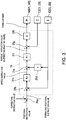
- Fig. 3 is a block diagram illustrating a configuration of a control system of the slave arm 1.
- a concrete electric configuration is illustrated, focusing on a motor controller 16.
- drive motors M1-M6 are provided to the respective joints JT1-JT6 of the slave arm 1, as one example of actuators, each of which relatively rotates two members connected by the joint.
- the drive motors M1-M6 are, for example, servo motors which are servo-controlled by the motor controller 16.
- the drive motors M1-M6 are provided with position sensors E1-E6 for detecting a rotational position thereof and current sensors C1-C6 for detecting current which controls the rotation, respectively.
- the position sensors E1-E6 may be sensors which is capable of detecting the rotational position, such as encoders, resolvers, or pulse generators. Note that, in the description of the drive motors M1-M6, the position sensors E1-E6, and the current sensors C1-C6, suffixes 1-6 are given to the alphabet corresponding to the respective joints JT1-JT6. Below, when an arbitrary joint is illustrated out of the joints JT1-JT6, the joint is referred to as "JT" while omitting the suffix, and the same is applied to the drive motor M, the position sensor E, and the current sensor C.
- the drive motors M, the position sensors E, and the current sensors C are electrically coupled to the motor controller 16.
- the motor controller 16 is capable of servo-controlling the plurality of drive motors M alone, motor controllers may be provided corresponding to the respective drive motors M.
- the motor controller 16 generates a drive instruction value (current instruction value) based on a positional instruction value, a servo gain, etc. which are acquired from the control unit 6 (in detail, a slave controller 61) described later, and supplies drive current corresponding to the drive instruction value to the drive motor M.
- An output rotational angle of the drive motor M is detected by the position sensor E, and is fed back to the motor controller 16.
- the functions of the motor controller 16 and the slave controller 61 may be implemented by a single circuit or a single arithmetic device.
- the inputted positional instruction value is given to a plus-side input of a subtractor 31b.
- a signal indicative of the rotational angle detected by the position sensor E (present positional value) is given to a minus-side input of the subtractor 31b.
- the subtractor 31b subtracts the rotational angle from the positional instruction value.
- the output of the subtractor 31b is given to a scale multiplier 31c where the output is amplified by a position gain Kp, and is then given to a plus-side input of a subtractor 31e.
- a signal obtained by differentiating the rotational angle from the position sensor E in a differentiator 31d is given.
- the output of the subtractor 31e is given to a scale multiplier 31f where the output is amplified by a speed gain K, and it is given to a plus-side input of a subtractor 31g.
- the current value from the current sensor C is given to a minus-side input of the subtractor 31g.
- the subtracted output of the subtractor 31g is inputted into an amplifier circuit 31h as the drive instruction value, and the drive current corresponding to the amplified drive instruction value is supplied to the drive motor M.
- the master device 20 is a means for receiving an operator's operation.
- the master device 20 of the remote control robot system 100 is a master arm 2, i.e., an articulated robotic arm (manipulator), and the system 100 is built so that the slave arm 1 operates so as to follow the motion of the master arm 2. That is, the master arm 2 is configured so that the position and posture of the slave arm 1 are instinctively operable.
- the master arm 2 is an articulated robotic arm having a plurality of joints JTml-JTm6, of which the number is the same as that of the slave arm 1, and is constructed by serially coupling a pedestal 25 and a plurality of links 21a-21f.
- the serially coupling structure of the links 21a-21f of the master arm 2 is substantially the same as that of the links 11a-11f of the slave arm 1 and, thus, detailed description thereof is omitted.
- a pseudo end effector which has a similarity to or corresponds to the end effector 12 attached to the slave arm 1 may be attached to the tip-end part of the sixth link 21f of the master arm 2.
- Drive motors Mm1-Mm6 are provided to the joints JTm1-JTm6, respectively, as one example of the actuator which relatively rotates the two components connected by the joint.
- the drive motors Mm1-Mm6 are, for example, servo motors which are servo-controlled by a motor controller 26.
- the drive motors Mm1-Mm6 are provided with position sensors Em1-Em6 (not illustrated) for detecting rotational positions thereof and current sensors Cm1-Cm6 (not illustrated) for detecting current which controls the rotations.
- the position sensors Em1-Em6 are, for example, encoders.
- suffixes 1-6 are given to the alphabet corresponding to the respective joints JTm1-JTm6.
- JTm joint is referred to as "JTm” while omitting the suffix, and the same is applied to the drive motor Mm, the position sensor Em, and the current sensor Cm.
- the drive motor Mm, the position sensor Em, and the current sensor Cm are electrically coupled to the motor controller 26.
- the motor controller 26 is capable of servo-controlling the plurality of drive motors Mm alone, motor controllers may be provided corresponding to the respective drive motors Mm.
- the motor controller 26 Similar to the motor controller 16, the motor controller 26 generates a drive instruction value (torque instruction value) based on a positional instruction value, a servo gain, etc. which are acquired from the control unit 6 (in detail, a master controller 62) described later, and supplies drive current corresponding to the drive instruction value to the drive motor Mm.
- the output rotational angle of the drive motor Mm is detected by the position sensor Em, and is fed back to the motor controller 26.
- the functions of the motor controller 26 and the master controller 62 may be implemented by a single circuit or a single arithmetic device.
- the slave arm 1 and the master arm 2 are articulated robotic arms with the same number of axes, but their link length ratios of the arm parts 13 and 23 are different. That is, the slave arm 1 and the master arm 2 may not have similar shapes.
- the link length of the link is a distance from the joint of the link on the base-end side to the joint on the tip-end side.
- the slave arm 1 and the master arm 2 according to this embodiment are 6-axes robotic arms, and the links which form the arm parts 13 and 23 are first to third links.
- the slave arm 1 one having the arm part 13 of a suitable link length ratio for the contents of work or the target workpiece is introduced into the system 100, while, as the master arm 2, one having the arm part 23 of a link length ratio which is easy to be handled by the operator is adopted.
- the link length ratio of the first link 11a, the second link 11b, and the third link 11c of the slave arm 1 is 1:4:2
- the link length ratio of the first link 21a, the second link 21b, and the third link 21c of the master arm 2 may be 1:2:2.
- the input device 7 is an input means, which is installed outside the workspace together with the master arm 2, receives an operating instruction from the operator, and inputs the received operating instruction into the control unit 6. Into the input device 7, operations other than operation according to the position and posture of the slave arm 1 are inputted.
- One or more operational input tools such as an operational input tool for selecting the control mode of the slave arm 1, and an emergency stop switch, which input operational instructions other than the position and posture of the slave arms 1 are provided to the input device 7.
- the one or more operational input tools may include, for example, known operational input tools, such as a touch panel, a key, a lever, a button, a switch, and a dial plate.
- a mobile terminal such as a programmable display device (pendant) and a tablet computer, may be used as the input device 7.
- the status acquiring device 5 is a means for acquiring the status information indicative of the status of each slave arm 1 in the workspace.
- the status information includes information utilized in order to recognize the position, the posture, etc. of the slave arm 1 in the workspace or the status around the slave arm 1. More specifically, the status information includes, for example, information required in order to enable the recognition of the status of the slave arm 1 and the status around the slave arm 1 in the workspaces, such as the position and posture of the slave arm 1 in the workspace, a spatial relationship between the slave arm 1 and the workpiece, or a spatial relationship between the slave arm 1 and an assembled component to which the workpiece is assembled.
- the status acquiring device 5 is implementable by, for example, an imaging device, such as a sensor or a camera, a communication device, an encoder, etc.
- the sensor may include, for example, a laser sensor, a radar sensor or the like for measuring the distance to or the position of an assembling component or the assembled component. Further, the sensor may include a stereoscopic camera which is a sensor for measuring the distance from the slave arm 1 to an object therearound by using image data obtained from a plurality of imaging devices.
- the communication device may include, for example, a communication device which acquires information from the assembling component or the assembled component, or a sensor and an imaging device installed at given positions in the workspace.
- the encoder may include, for example, an encoder capable of detecting an amount of movement or the position of the slave arm 1.
- the status acquiring device 5 sequentially acquires the status information, the acquired status information is inputted into the control unit 6 described later, and the information is used for the motion control of the slave arm 1 in the control unit 6. Further, the control unit 6 may be configured to control the output device 4 to output the status information.
- the status acquiring device 5 may be attached to slave arm 1 itself, or may be attached to a suitable position in the workspace. Moreover, the number of status acquiring devices 5 to be attached may be one, or may be more. A suitable number of the status acquiring devices 5 may be attached at positions where they can appropriately acquire the status information and, thus, the attaching position and the attachment number are arbitrary.
- the output device 4 is to output the information transmitted from the control unit 6.
- the output device 4 is installed at a position where the operator who operates the master arm 2 is easy to visually recognize the device.
- the output device 4 includes at least a display device 41, and may further include a printer, a speaker, a hazard light, etc.
- the information transmitted from the control unit 6 is outputted and displayed by the display device 41.
- the speaker outputs the information transmitted from the control unit 6 as sound.
- the printer prints the information transmitted from the control unit 6 on a recording media, such as paper.
- each display device 41 may output the status information of the corresponding slave arm 1.
- the color of the background of the display device 41 where the operating slave arm 1 is displayed may be changed, or an indicating lamp may be provided around the display device 41.
- the operating slave arm 1 is an object to be operated by the master device 20, and is the slave arm 1 on which operation is reflected by the operation received by the master device 20.
- the storage device 8 stores various task programs used for the control of the slave arm 1.
- the task program may be created as an operation flow for every work.
- the task program is created, for example, by teaching, and is stored in the storage device 8 so as to be associated with identifying information and task of the slave arm 1. Note that, although the storage device 8 is described independently from the control unit 6, a storage device provided to the control unit 6 may function as the storage device 8.
- the storage device 8 stores operation sequence information which is created beforehand.
- the operation sequence information is information related to an operation sequence which defines a series of work processes to be carried out by the slave arm 1 in the workspace.
- an operating order of the work process is associated with the control mode of the slave arm 1.
- each work process is associated with task program(s) for causing the slave arm 1 to automatically execute the work.
- the operation sequence information may include the program(s) for causing the slave arm 1 for each work process to automatically execute the work.
- Fig. 4 illustrates one example of the operation sequence information stored in the storage device 8.
- the operation sequence of the seat assembling work to the automobile body is comprised of a component extracting task T1 in which a seat is taken out from a container, a component conveying task T2 in which the seat is conveyed to near an assembling position of the body, and a component assembling task T3 in which the seat near the assembling position is assembled to the assembling position, and these tasks T1-P3 are repeatedly executed in this order.
- the component extracting task T1 and the component conveying task T2 among the operation sequence are "automatic parts" in which the slave arm 1 is operated in the automatic mode.
- the automatic part among the operation sequence is associated with the automatic mode as the control mode.
- the component assembling task T3 among the operation sequence is a "selected part" in which the slave arm 1 operates in the control mode selected from the automatic mode, the manual mode, and the correctable automatic mode.
- the selected part among the operation sequence is not associated with a specific control mode, and the control mode is selectable.
- Fig. 4 the operation sequence of the first slave arm 1A and the operation sequence of the second slave arm 1B are illustrated in parallel. While the first slave arm 1A executes the component assembling task T3 (i.e., the selected part), the second slave arm 1B executes the component extracting task T1 and the component conveying task T2. Moreover, while the second slave arm 1B executes the component assembling task T3 (i.e., the selected part), the first slave arm 1A executes the component extracting task T1 and the component conveying task T2.
- the operation sequence is created so that the selected part appears alternately for the first slave arm 1A and the second slave arm 1B, and the selected part of the first slave arm 1A and the selected part of the second slave arm 1B do not overlap with each other in time.
- the plurality of slave arms 1, the master device 20, the output device 4, the status acquiring device 5, the input device 7, and the storage device 8 are communicatably connected to the control unit 6 in a wired or wireless manner.
- the control unit 6 is a so-called computer, and has a processor, such as a CPU, and a memory, such as a ROM and/or a RAM (none of them is illustrated).
- the memory stores control program(s) to be executed by the control unit 6, various fixed data, etc.
- the processor performs, for example, data transmission and reception with external devices, such as the input device 7, the output device 4, and the storage device 8. Moreover, the processor performs inputs of detection signals from various sensors and outputs of the control signal to each controlled target.
- the processor reads and executes software, such as the program stored in the memory to perform processing for controlling various operation of the system 100.
- control unit 6 may execute each processing by a centralized control of a single computer, or may execute each processing by a distributed control of a plurality of collaborating computers.
- control unit 6 may be comprised of a microcontroller, a programmable logic controller (PLC), etc.
- the control unit 6 includes a host controller 60, a plurality of slave controllers 61, the master controller 62, a receiver 63, an output controller 64, and a corrector 65 as functional blocks. Although in Fig. 2 these functional blocks are collectively illustrated as a single control unit 6, each functional block or a combination of two or more functional blocks may be implemented by one or more independent computers. In this case, part of these functional blocks may be arranged in the workspace, and the remainder may be arranged outside the workspace.
- the slave controller 61 controls the operation of the slave arm 1.
- the slave controller 61 includes a first slave controller 61A which controls the operation of the first slave arm 1A, and a second slave controller 61B which controls the operation of the second slave arm 1B.
- the slave controller 61 may be provided according to the number of slave arms 1 provided to the system 100.
- the slave controller 61 reads the task program stored in the storage device 8, generates the positional instruction value according to the task program, and gives the positional instruction value, a servo gain, etc. to the motor controller 16 of the slave arm 1. Moreover, in the manual mode, the slave controller 61 generates the positional instruction value based on the operation signal which is accepted by the master arm 2 and received by the receiver 63, and gives the positional instruction value, the servo gain, etc. to the motor controller 16 of the slave arm 1.
- the slave controller 61 reads the task program stored in the storage device 8, generates a positional instruction value (or a corrected positional instruction value) based on the task program and a correction instruction value acquired from the corrector 65, and gives the positional instruction value, the servo gain, etc. to the motor controller 16 (see Fig. 3 ). Note that, in the correctable automatic mode, if the correction instruction value is not given from the corrector 65, the correction instruction value is calculated as zero.
- the master controller 62 controls the operation of the master arm 2.
- the master controller 62 operates the master arm 2 so that the master arm 2 moves or changes in the posture according to an external force applied by the operator to the master arm 2. That is, the operating force of the operator is assisted by the operation of the master arm 2.
- the master controller 62 may operate the master arm 2 so that a hand part of the master arm 2 moves along a given route.
- the master controller 62 automatically changes the posture of the master arm 2 so that the posture of the master arm 2 corresponds to a new posture of the operating slave arm 1. Specifically, when the operating slave arm 1 is switched, the master controller 62 acquires the positional information detected by the position sensor E of each joint JT of the new operating slave arm 1, and operates each joint JTm of the master arm 2 through the motor controller 26 so that the rotational positions of the corresponding joints become substantially equal between the operating slave arm 1 and the master arm 2.
- n-th joint JTn of the operating slave arm 1 and the n-th joint JTmn of the master arm 2 are equal (here, n is an integer from 1 to 6).
- the receiver 63 receives the input signal transmitted from the outside of the control unit 6.
- the input signal received by the receiver 63 may include, for example, a signal transmitted from the master arm 2, a signal transmitted from the input device 7, a signal indicative of the status information transmitted from the status acquiring device 5, etc.
- the output controller 64 controls the output device 4 to output to the output device 4 information to be notified the operator. For example, when starting the selected part among the operation sequence, the output device 4 outputs to the display device 41 information for identifying the target slave arm 1, and information for urging the input of selection of the control mode of the slave arm 1. Moreover, for example, when the control modes of the slave arm 1 are the manual mode and the correctable automatic mode, the output device 4 outputs to the display device 41 the status information and an operating status of the slave arm 1 operated by the master arm 2. Moreover, for example, when a failure occurs to the system 100, the output device 4 outputs an alarm to the speaker or the display device 41.
- the corrector 65 corrects the motion of the slave arm 1 based on the operation received by the master arm 2, when the control mode of the slave arm 1 is the correctable automatic mode. For example, when the position of the hand part of the master arm 2 changes when the operator moves the master arm 2, the master arm 2 receives the displacement of the hand part as a correcting instruction, and inputs it into the control unit 6. When the receiver 63 receives the correcting instruction signal while the control mode of the slave arm 1 is the correctable automatic mode, the corrector 65 generates a correction instruction value based on the correcting instruction signal. An equation or map by which the correction instruction value is calculated from the correcting instruction signal is stored beforehand.
- Such a correction instruction value may be a value, for example, proportional to an amount of displacement of the hand part of the master arm 2.
- the generated correction instruction value is transmitted to the slave controller 61, and the corrected positional instruction value is outputted from the slave controller 61 to the motor controller 16 (see Fig. 3 ).
- the host controller 60 reads the operation sequence information stored in the storage device 8, and outputs instructions to the slave controller 61, the master controller 62, the output controller 64, and the corrector 65 so that the slave arm 1, the master arm 2, the output device 4, and the status acquiring device 5 operate in accordance with the operation sequence information.
- the control unit 6 first reads the given operation sequence information stored in the storage device 8, and starts the control of the system 100 in accordance with the operation sequence information.
- the control unit 6 first reads and executes the task program of the component extracting task T1 from the storage device 8. Next, the control unit 6 reads and executes the task program of the component conveying task T2. In the component extracting task T1 and the component conveying task T2, the control unit 6 controls the operation of the first slave arm 1A in the automatic mode.
- the control unit 6 displays on the display device 41 a selection screen for urging the operator to select the control mode of the subsequent component assembling task T3.
- the control unit 6 causes the display device 41 to output the status information of the slave arm 1 for which the control mode is to be selected (here, the first slave arm 1A).
- the status information which is displayed on and outputted to the display device 41 may include the identifying information of the slave arm 1 which is currently displayed, contents of the process to be performed next, or the like.
- the operator visually recognizes the status information of the first slave arm 1A displayed on the display device 41, and selects one of the three control modes.
- the selection of the control mode by the operator is received by the master device 20 or the input device 7, and is inputted into the control unit 6.
- the control unit 6 when the automatic mode is selected, the control unit 6 reads the task program of the component assembling task T3 from the storage device 8, and controls the operation of the first slave arm 1A in the automatic mode. Moreover, when the manual mode is selected, the control unit 6 controls the operation of the first slave arm 1A in the manual mode. Alternatively, when the correctable automatic mode is selected, the control unit 6 controls the operation of the first slave arm 1A in the correctable automatic mode.
- control unit 6 operates the master arm 2 so that the posture of the operating slave arm 1 corresponds to the posture of the master arm 2.
- control unit 6 when either one of the manual mode and the correctable automatic mode is selected, the control unit 6 causes the display device 41 to display and output the status information of the operating slave arm 1 throughout the process.
- the control unit 6 causes the second slave arm 1B to perform the component extracting task T1 and the component conveying task T2, in parallel with the component assembling task T3 of the first slave arm 1A. Then, once the component assembling task T3 of the first slave arm 1A is finished, and the component extracting task T1 and the component conveying task T2 of the second slave arm 1B are finished, the control unit 6 causes the second slave arm 1B to start the component assembling task T3, and causes the first slave arm 1A to start the component extracting task T1. Thus, the control unit 6 sequentially advances the work process in accordance with the operation sequence.
- the remote control robot system 100 includes the master device 20 which receives the operator's operation, the plurality of slave arms 1, the storage device 8 which stores the operation sequence information and the task program, and the slave controller 61 (slave control device) which operates the slave arms 1 based on the operation sequence information.
- Each slave arm 1 has the plurality of control modes of the automatic mode in which the slave arm is operated based on the prestored task program, the manual mode in which the slave arm is operated based on the operator's operation received by the master device 20, and the correctable automatic mode in which the slave arm is operated based on the task program while the operation is sequentially corrected by the operator's operation received by the master device 20.
- the operation sequence information includes the automatic part in which the slave arm 1 performs a work in the automatic mode, and the selected part in which the slave arm 1 performs a work in the selected one of the plurality of control modes, and the selected parts of the plurality of slave arms are configured so as not to overlap with each other in time. Then, based on the operation sequence information, the control unit 6 operates the slave arm 1 in the automatic mode in the automatic part, and operates the slave arm 1 in the control mode that is selected by the operator from the plurality of control modes for every selected part in the selected part.
- a method of operating the remote control robot system 100 includes the automatic part in which the slave arm 1 performs a work in the automatic mode, and the selected part in which the slave arm 1 performs a work in one selected from the plurality of control modes.
- the method includes a step for creating the operation sequence information where the selected parts of the plurality of slave arms 1 do not overlap with each other in time, and a step for causing the slave arm 1 to perform the work based on the operation sequence information, by operating the slave arm 1 in the automatic mode in the automatic part, and operating the slave arm 1 in the control mode that is selected by the operator from the plurality of control modes for every selected part in the selected part.
- the operator is able to select the control mode of the slave arm 1 from the automatic mode, the manual mode, and the correctable automatic mode according to the contents of work or the status of the slave arm 1.
- the selection of the control mode can be performed by the judgment of the operator.
- works such as gripping of a vulnerable component, a precision fitting, an accurate positioning or axial alignment, etc. are suitable to be performed in the manual mode or the correctable automatic mode in which the operator's operation is reflectable on the motion of the slave arm 1.
- the correctable automatic mode may be selected.
- a nonstop robot system is achieved by the operator selecting the control mode suitable for the status, from the plurality of control modes, for every work.
- the remote control robot system 100 and the operating method of the same the manual mode and the correctable automatic mode which require the operator's operation do not appear simultaneously in the plurality of slave arms 1. Therefore, a series of work in which the automatic part and the selected part are mixed is efficiently performed using the two or more slave arms 1A and 1B, and the contents of work of the system 100 are extended, as compared with the case where one slave arm is used. That is, the work of the slave arm 1A in the automatic mode, and the work of the slave arm 1B in one of the control modes among the automatic mode, the manual mode, and the correctable automatic mode are simultaneously performed. Moreover, since one operator remotely operates the plurality of slave arms 1, idle times of the slave arm and the operator are shortened. Therefore, an improvement in the work efficiency of the system 100 can be expected.
- the remote control robot system 100 includes the master controller 62 (master control device) which acquires, when starting the manual mode or the correctable automatic mode, the rotational position of each joint JT of the operating slave arm 1 among the plurality of slave arms 1, and operates the master arm 2 so that the rotational positions of the corresponding joints JTn and JTmn (n is an integer from 1 to 6) of the master arm 2 and the operating slave arm 1 become equal.
- master controller 62 master control device
- the step at which the slave arm 1 performs the work includes receiving, when starting the selected part, a selection of one of the plurality of control modes, and operating the master arm 2, when the received control mode is the manual mode or the correctable automatic mode, so that the rotational positions of the corresponding joints JTn and JTmn (n is an integer from 1 to 6) of the operating slave arm 1 among the plurality of slave arms, and the master arm 2 become equal.
- the remote control robot system 100 since the rotational positions of the corresponding joints JTn and JTmn of the master arm 2 and the operating slave arm 1 are equal when starting the work in the manual mode or the correctable automatic mode, the operator can learn the status of each joint JT of the operating slave arm 1 by visually recognizing the master arm 2. Therefore, even if the status information of the operating slave arm 1 displayed on the display device 41 does not show the entire operating slave arm 1, the operator can learn the general status of the operating slave arm 1.
- the numbers of joints of the plurality of slave arms 1 are equal
- the master device 20 is the master arm 2 having the same number of joints as the plurality of slave arms 1
- the link length ratio of the arm part 23 of the master arm 2 differs from the link length ratio of at least one arm part 13 of the slave arm 1.
- the master arm 2 and the slave arm 1 are not limited to have the similarity in their shapes, but the master arm 2 is constructed so as to be easily operable by the operator and the slave arm 1 is constructed so as to be suitable for the contents of work.
- the remote control robot system 100 further includes the status acquiring device 5 which acquires the status information of the plurality of slave arms 1, and the output device 4 which outputs the status information of the operating slave arm 1 among the plurality of slave arms 1 when starting the manual mode or the correctable automatic mode.
- the operator is capable of operating the master device 20, while checking the status information of the operating slave arm 1 outputted to the output device 4 (e.g., the display device 41).
- the output device 4 may be configured to display and output guidance for the manual operation to the operator.
- the master devices 20 is a robotic arm of a non-similar shape to the slave arm 1, but the form of the master device 20 is not limited to this shape.
- a robotic arm of a similar shape to the slave arm 1 may be adopted as the master device 20. That is, the master device 20 may be a master arm having the same number of joints as the plurality of slave arms 1, and the link length ratio of the arm part of the master arm may be equal to the link length ratio of at least one arm part 13 of the slave arm 1.
- the master controller 62 may operate the master arm so that the rotational positions of the corresponding joints become equal between the master arm and the operating slave arm 1, when starting the manual mode or the correctable automatic mode, similar to the above embodiment.
- the master device 20 takes the corresponding posture to the slave arm 1, and the operator is able to sensuously grasp the posture of the slave arm 1 while looking at the master device 20.
- the master device 20 is the robotic arm, but the master device 20 is not limited to this structure.
- the master device 20 may be a horizontal or vertical articulated robot having three or more degrees of freedom, and may be a combination of one or more of known operating means, such as a joy stick, a control lever, an operating button, an operation dial plate, a tablet computer, and a programmable display device (pendant).
Abstract
Description
- The present disclosure relates to a remote control robot system provided with a master device and a slave arm, and a method of operating the remote control robot system.
- Conventionally, remote control robot systems provided with a master device (i.e., a remote control device) and a slave arm which operates according to operation of the master device are known. As the master device, a manipulator, a control lever, an operating button, etc. may be used. In such remote control robot systems, some of them are configured so that the posture of the slave arm is made to follow the posture of a robotic arm as the master device, and a reaction force acting on the slave arm is transmitted to an operator through the master device. Such a kind of technology is disclosed in
Patent Document 1. -
Patent Document 1 discloses a remote control robot system having three operating modes of an automatic operating mode, a manual operating mode, and a manual operating mode with restraint which assists a manual operation, such as restraining to a hand posture by a slave operation managing means, and switches the operating mode according to a work sequence plan. In the automatic operating mode, the slave operation managing means causes the slave arm to execute a work in accordance with a given program. Moreover, in the manual operating mode and the manual operating mode with restraint, mainly, an interface means causes the slave arm to execute a work according to operation inputted into the master device by an operator. In addition, in the manual operating mode with restraint, the slave operation managing means executes operation which assists the operation. - Moreover, in the remote control robot system disclosed in
Patent Document 1, a remote control method is disclosed, which includes creating a work sequence plan in which a manual operation part and an automatic operation part are mixed based on data indicative of the operator's skill and a given work objective, operates the system in the automatic operating mode for the automatic operation part of the work sequence plan, and operates the system in the manual operating mode or the manual operating mode with restraint of the work sequence plan. - [Patent Document 1]
JP1996-005018B2 - In the technology of
Patent Document 1, when the mode is switched to the manual operating mode or the manual operating mode with restraint, the slave operation managing means does not use the program which is used in the automatic operating mode. Thus, in the manual operating mode or the manual operating mode with restraint, an operator's load becomes excessive and the work efficiency is lowered. - Moreover, although
Patent Document 1 describes that the remote control robot system may be provided with a plurality of slave arms, it is based on the assumption that the rate of the automatic operation is large. Thus, when the remote control robot system is provided with the plurality of slave arms, the operations of the slave arms may differ from each other, and the operator's load may become remarkably excessive. Therefore, the room of improvement is left behind in the technology ofPatent Document 1 for performing an efficient work using the plurality of slave arms. - According to one aspect of the present disclosure, a method of operating a remote control robot system provided with a master device and a plurality of slave arms is provided. Each of the slave arms has a plurality of control modes of an automatic mode in which the slave arm is operated based on a prestored task program, a manual mode in which the slave arm is operated based on an operator's operation received by the master device, and a correctable automatic mode in which the slave arm is operated based on the task program while the operation is sequentially corrected by an operator's operation received by the master device. The method includes a step of creating operation sequence information that includes an automatic part in which the slave arm performs a work in the automatic mode, and a selected part in which the slave arm performs a work in one selected from the plurality of control modes, and the selected parts do not overlap with each other in time among the plurality of the slave arms, and a step of the slave arm performing the work based on the operation sequence information, by operating the slave arm in the automatic mode in the automatic part, and operating the slave arm in the control mode that is selected from the plurality of control modes for every selected part in the selected part.
- According to another aspect of the present disclosure, a remote control robot system is provided, which includes a master device configured to receive an operator's operation, a plurality of slave arms having a plurality of control modes of an automatic mode in which the slave arm is operated based on a prestored task program, a manual mode in which the slave arm is operated based on the operator's operation received by the master device, and a correctable automatic mode in which the slave arm is operated based on the task program while the operation is sequentially corrected by the operator's operation received by the master device, a storage device configured to store operation sequence information that includes an automatic part in which the slave arm performs a work in the automatic mode, and a selected part in which the slave arm performs a work in one selected from the plurality of control modes, and the selected parts do not overlap with each other in time among the plurality of slave arms, and the task program, and a slave control device configured to cause the slave arm, based on the operation sequence information, to operate in the automatic mode in the automatic part, and to operate the slave arm in the control mode that is selected from the plurality of control modes for every selected part in the selected part.
- According to the remote control robot system and the method of operating the same described above, the control mode of the slave arm is able to be selected from the automatic mode, the manual mode, and the correctable automatic mode according to the contents of work or a status of the slave arm. The selection of the control mode can be performed by the judgment of the operator. For example, when occurring of a failure is expected if the slave arm is completely operated automatically, the slave arm may be operated in the correctable automatic mode. In the correctable automatic mode, since the automatic operation of the slave arm is used as the basis, and the operation is correctable by the operator's operation, the operator's load is less and a reduction of the work efficiency is suppressed, as compared with the manual mode. Thus, a nonstop robot system is achieved by the operator selecting the control mode suitable for the status from the plurality of control modes.
- Moreover, the manual mode and the correctable automatic mode which require the operator's operation do not appear simultaneously in the plurality of slave arms. Therefore, the operator remotely operates the plurality of slave arms with one master device, and idle times of the slave arm and the operator are shortened. Thus, the efficient work can be performed using the plurality of slave arms.
- According to the remote control robot system and the method of operating the same of the present disclosure, the efficient work can be performed using the plurality of slave arms.
-
-
Fig. 1 is a view illustrating an appearance of an automobile assembly line into which a remote control robot system according to one embodiment of the present disclosure is introduced. -
Fig. 2 is a block diagram schematically illustrating a configuration of the remote control robot system. -
Fig. 3 is a block diagram illustrating a configuration of a control system of a slave arm. -
Fig. 4 is a view illustrating one example of operation sequence information. - Hereinafter, one embodiment of the present disclosure is described with reference to the accompanying drawings.
-
Fig. 1 is a view illustrating an appearance of an automobile assembly line provided with a remotecontrol robot system 100 according to one embodiment of the present disclosure, andFig. 2 is a block diagram schematically illustrating a configuration of the remotecontrol robot system 100. As illustrated inFigs. 1 and2 , the remotecontrol robot system 100 is a master-slave type robot system, and includes a plurality of slave arms 1 (1A and 1B), amaster device 20, an input device 7, anoutput device 4, astatus acquiring device 5, and a control unit 6 which comprehensively controls thesystem 100. Herein, when not distinguishing the plurality ofslave arms slave arm 1." - In
Fig. 1 , illustrated is the automobile assembly line provided with a conveyor line of a workpiece W, which is formed by aconveyor 99 in a workspace, the plurality ofslave arms master device 20 installed at a position distant from the workspace (outside of the workspace). In this automobile assembly line, theslave arm 1 is capable of performing a work, such as transferring of the workpiece W, assembling and relocating of a component, posture conversion, and painting. Note that the remotecontrol robot system 100 according to the present disclosure is not limited to such an automobile assembly line, but may be applicable widely to various production facilities. - The
slave arm 1 according to this embodiment has three control modes of an automatic mode, a manual mode, and a correctable automatic mode. The control mode of theslave arm 1 can be switched so that operation is controlled in one selected from the plurality of control modes. - The control mode in which the
slave arm 1 is operated according to a preset task program is herein referred to as "the automatic mode." In the automatic mode, theslave arm 1 automatically performs a given work without the operation of themaster device 20 by an operator, similar to a conventional teaching playback robot. - Moreover, the control mode in which the
slave arm 1 is operated based on the operator's operation received by themaster device 20 is herein referred to as "the manual mode." Themaster device 20 is capable of receiving operation inputted by the operator directly operating themaster device 20. Note that, in the manual mode, the operator's operation received by themaster device 20, and/or the motion of theslave arm 1 which is operated based on the operation may be corrected automatically. - Moreover, the control mode in which the
slave arm 1 is operated according to the preset task program while the operation is sequentially corrected according to the operator's operation received by themaster device 20 is herein referred to as "the correctable automatic mode." In the correctable automatic mode, the motion of theslave arm 1 which is operated according to the preset task program is corrected based on the operator's operation received by themaster device 20. - Below, each element of the remote
control robot system 100 is described in detail. - In
Fig. 1 , twoslave arms 1 of thefirst slave arm 1A and thesecond slave arm 1B, which are installed so as to be separated from each other in parallel to the conveyor line of the workpiece W, are illustrated. The twoslave arms 1 are vertical articulated robots, and have substantially the same structure except forend effectors 12. Note that the forms of the plurality ofslave arms 1 provided to the remotecontrol robot system 100 are not limited to this embodiment, but eachslave arm 1 may be a horizontal or vertical articulated robotic arm (manipulator) having three or more joints (axes). Moreover, the plurality ofslave arms 1 may include multiple kinds of robotic arms having different link lengths and different number of joints. - As illustrated in
Fig. 2 , theslave arm 1 is an articulated robotic arm having a plurality of joints JT1-JT6, which is comprised of a serially-connected body of a plurality oflinks 11a-11f and apedestal 15 which supports the serially-connected body. In more detail, in the first joint JT1, thepedestal 15 is coupled to a base-end part of thefirst link 11a so as to be rotatable about an axis extending in the vertical directions. In the second joint JT2, a tip-end part of thefirst link 11a is coupled to a base-end part of thesecond link 11b so as to be rotatable about an axis extending in horizontal directions. In the third joint JT3, a tip-end part of thesecond link 11b is rotatably coupled to the base-end part of thethird link 11c about an axis extending in horizontal directions. In the fourth joint JT4, a tip-end part of thethird link 11c is rotatably coupled to a base-end part of thefourth link 11d about an axis extending in the longitudinal directions of thefourth link 11d. In the fifth joint JT5, a tip-end part of thefourth link 11d is rotatably coupled to a base-end part of thefifth link 11e about an axis perpendicular to the longitudinal directions of thefourth link 11d. In the sixth joint JT6, a tip-end part of thefifth link 11e is coupled to a base-end part of thesixth link 11f so as to be twistable. A mechanical interface is provided to a tip-end part of thesixth link 11f. The end effector 12 (seeFig. 1 ) corresponding to the contents of work is attachably and detachably mounted to the mechanical interface. - An
arm part 13 of theslave arm 1 is formed with the connected body of the links and joints, which is comprised of the first joint JT1, thefirst link 11a, the second joint JT2, thesecond link 11b, the third joint JT3, and thethird link 11c, which are described above. Moreover, awrist part 14 of theslave arm 1 is formed with the connected body of the links and joints, which is comprised of the fourth joint JT4, thefourth link 11d, the fifth joint JT5, thefifth link 11e, the sixth joint JT6, and thesixth link 11f, which are described above. Thearm part 13 takes the role of positioning theend effector 12, and thewrist part 14 takes the role of orientating theend effector 12. -
Fig. 3 is a block diagram illustrating a configuration of a control system of theslave arm 1. In this figure, a concrete electric configuration is illustrated, focusing on amotor controller 16. As illustrated inFig. 3 , drive motors M1-M6 are provided to the respective joints JT1-JT6 of theslave arm 1, as one example of actuators, each of which relatively rotates two members connected by the joint. The drive motors M1-M6 are, for example, servo motors which are servo-controlled by themotor controller 16. Moreover, the drive motors M1-M6 are provided with position sensors E1-E6 for detecting a rotational position thereof and current sensors C1-C6 for detecting current which controls the rotation, respectively. The position sensors E1-E6 may be sensors which is capable of detecting the rotational position, such as encoders, resolvers, or pulse generators. Note that, in the description of the drive motors M1-M6, the position sensors E1-E6, and the current sensors C1-C6, suffixes 1-6 are given to the alphabet corresponding to the respective joints JT1-JT6. Below, when an arbitrary joint is illustrated out of the joints JT1-JT6, the joint is referred to as "JT" while omitting the suffix, and the same is applied to the drive motor M, the position sensor E, and the current sensor C. - The drive motors M, the position sensors E, and the current sensors C are electrically coupled to the
motor controller 16. Although themotor controller 16 according to this embodiment is capable of servo-controlling the plurality of drive motors M alone, motor controllers may be provided corresponding to the respective drive motors M. - The
motor controller 16 generates a drive instruction value (current instruction value) based on a positional instruction value, a servo gain, etc. which are acquired from the control unit 6 (in detail, a slave controller 61) described later, and supplies drive current corresponding to the drive instruction value to the drive motor M. An output rotational angle of the drive motor M is detected by the position sensor E, and is fed back to themotor controller 16. Note that the functions of themotor controller 16 and theslave controller 61 may be implemented by a single circuit or a single arithmetic device. - When the positional instruction value is inputted into the
motor controller 16 from the control unit 6 (in detail, the slave controller 61), the inputted positional instruction value is given to a plus-side input of a subtractor 31b. A signal indicative of the rotational angle detected by the position sensor E (present positional value) is given to a minus-side input of the subtractor 31b. The subtractor 31b subtracts the rotational angle from the positional instruction value. The output of the subtractor 31b is given to ascale multiplier 31c where the output is amplified by a position gain Kp, and is then given to a plus-side input of asubtractor 31e. To a minus-side input of thesubtractor 31e, a signal obtained by differentiating the rotational angle from the position sensor E in adifferentiator 31d is given. The output of thesubtractor 31e is given to ascale multiplier 31f where the output is amplified by a speed gain K, and it is given to a plus-side input of asubtractor 31g. The current value from the current sensor C is given to a minus-side input of thesubtractor 31g. The subtracted output of thesubtractor 31g is inputted into anamplifier circuit 31h as the drive instruction value, and the drive current corresponding to the amplified drive instruction value is supplied to the drive motor M. - The
master device 20 is a means for receiving an operator's operation. Themaster device 20 of the remotecontrol robot system 100 according to this embodiment is amaster arm 2, i.e., an articulated robotic arm (manipulator), and thesystem 100 is built so that theslave arm 1 operates so as to follow the motion of themaster arm 2. That is, themaster arm 2 is configured so that the position and posture of theslave arm 1 are instinctively operable. - The
master arm 2 is an articulated robotic arm having a plurality of joints JTml-JTm6, of which the number is the same as that of theslave arm 1, and is constructed by serially coupling apedestal 25 and a plurality oflinks 21a-21f. The serially coupling structure of thelinks 21a-21f of themaster arm 2 is substantially the same as that of thelinks 11a-11f of theslave arm 1 and, thus, detailed description thereof is omitted. A pseudo end effector which has a similarity to or corresponds to theend effector 12 attached to theslave arm 1 may be attached to the tip-end part of thesixth link 21f of themaster arm 2. - Drive motors Mm1-Mm6 (not illustrated) are provided to the joints JTm1-JTm6, respectively, as one example of the actuator which relatively rotates the two components connected by the joint. The drive motors Mm1-Mm6 are, for example, servo motors which are servo-controlled by a
motor controller 26. Moreover, the drive motors Mm1-Mm6 are provided with position sensors Em1-Em6 (not illustrated) for detecting rotational positions thereof and current sensors Cm1-Cm6 (not illustrated) for detecting current which controls the rotations. The position sensors Em1-Em6 are, for example, encoders. Note that, in the description of the drive motors Mm1-Mm6, the position sensors Em1-Em6, and the current sensors Cm1-Cm6, suffixes 1-6 are given to the alphabet corresponding to the respective joints JTm1-JTm6. Below, when an arbitrary joint is illustrated out of the joints JTm1-JTm6, the joint is referred to as "JTm" while omitting the suffix, and the same is applied to the drive motor Mm, the position sensor Em, and the current sensor Cm. - Similar to the drive system of the
slave arm 1, the drive motor Mm, the position sensor Em, and the current sensor Cm are electrically coupled to themotor controller 26. Although themotor controller 26 according to this embodiment is capable of servo-controlling the plurality of drive motors Mm alone, motor controllers may be provided corresponding to the respective drive motors Mm. - Similar to the
motor controller 16, themotor controller 26 generates a drive instruction value (torque instruction value) based on a positional instruction value, a servo gain, etc. which are acquired from the control unit 6 (in detail, a master controller 62) described later, and supplies drive current corresponding to the drive instruction value to the drive motor Mm. The output rotational angle of the drive motor Mm is detected by the position sensor Em, and is fed back to themotor controller 26. Note that the functions of themotor controller 26 and themaster controller 62 may be implemented by a single circuit or a single arithmetic device. - The
slave arm 1 and themaster arm 2 are articulated robotic arms with the same number of axes, but their link length ratios of thearm parts slave arm 1 and themaster arm 2 may not have similar shapes. Note that, the link length of the link is a distance from the joint of the link on the base-end side to the joint on the tip-end side. Theslave arm 1 and themaster arm 2 according to this embodiment are 6-axes robotic arms, and the links which form thearm parts slave arm 1, one having thearm part 13 of a suitable link length ratio for the contents of work or the target workpiece is introduced into thesystem 100, while, as themaster arm 2, one having thearm part 23 of a link length ratio which is easy to be handled by the operator is adopted. For example, when the link length ratio of thefirst link 11a, thesecond link 11b, and thethird link 11c of theslave arm 1 is 1:4:2, the link length ratio of thefirst link 21a, thesecond link 21b, and thethird link 21c of themaster arm 2 may be 1:2:2. - The input device 7 is an input means, which is installed outside the workspace together with the
master arm 2, receives an operating instruction from the operator, and inputs the received operating instruction into the control unit 6. Into the input device 7, operations other than operation according to the position and posture of theslave arm 1 are inputted. One or more operational input tools, such as an operational input tool for selecting the control mode of theslave arm 1, and an emergency stop switch, which input operational instructions other than the position and posture of theslave arms 1 are provided to the input device 7. The one or more operational input tools may include, for example, known operational input tools, such as a touch panel, a key, a lever, a button, a switch, and a dial plate. Alternatively, a mobile terminal, such as a programmable display device (pendant) and a tablet computer, may be used as the input device 7. - The
status acquiring device 5 is a means for acquiring the status information indicative of the status of eachslave arm 1 in the workspace. The status information includes information utilized in order to recognize the position, the posture, etc. of theslave arm 1 in the workspace or the status around theslave arm 1. More specifically, the status information includes, for example, information required in order to enable the recognition of the status of theslave arm 1 and the status around theslave arm 1 in the workspaces, such as the position and posture of theslave arm 1 in the workspace, a spatial relationship between theslave arm 1 and the workpiece, or a spatial relationship between theslave arm 1 and an assembled component to which the workpiece is assembled. - The
status acquiring device 5 is implementable by, for example, an imaging device, such as a sensor or a camera, a communication device, an encoder, etc. The sensor may include, for example, a laser sensor, a radar sensor or the like for measuring the distance to or the position of an assembling component or the assembled component. Further, the sensor may include a stereoscopic camera which is a sensor for measuring the distance from theslave arm 1 to an object therearound by using image data obtained from a plurality of imaging devices. The communication device may include, for example, a communication device which acquires information from the assembling component or the assembled component, or a sensor and an imaging device installed at given positions in the workspace. The encoder may include, for example, an encoder capable of detecting an amount of movement or the position of theslave arm 1. - The
status acquiring device 5 sequentially acquires the status information, the acquired status information is inputted into the control unit 6 described later, and the information is used for the motion control of theslave arm 1 in the control unit 6. Further, the control unit 6 may be configured to control theoutput device 4 to output the status information. Thestatus acquiring device 5 may be attached toslave arm 1 itself, or may be attached to a suitable position in the workspace. Moreover, the number ofstatus acquiring devices 5 to be attached may be one, or may be more. A suitable number of thestatus acquiring devices 5 may be attached at positions where they can appropriately acquire the status information and, thus, the attaching position and the attachment number are arbitrary. - The
output device 4 is to output the information transmitted from the control unit 6. Theoutput device 4 is installed at a position where the operator who operates themaster arm 2 is easy to visually recognize the device. Theoutput device 4 includes at least adisplay device 41, and may further include a printer, a speaker, a hazard light, etc. The information transmitted from the control unit 6 is outputted and displayed by thedisplay device 41. For example, the speaker outputs the information transmitted from the control unit 6 as sound. Moreover, for example, the printer prints the information transmitted from the control unit 6 on a recording media, such as paper. - Note that, as illustrated in
Fig. 1 , when onedisplay device 41 is provided as theoutput device 4 perslave arm 1, eachdisplay device 41 may output the status information of thecorresponding slave arm 1. In this case, in order for the operator to recognize whichslave arm 1 is the operatingslave arm 1, the color of the background of thedisplay device 41 where the operatingslave arm 1 is displayed may be changed, or an indicating lamp may be provided around thedisplay device 41. Here, "the operatingslave arm 1" is an object to be operated by themaster device 20, and is theslave arm 1 on which operation is reflected by the operation received by themaster device 20. - The
storage device 8 stores various task programs used for the control of theslave arm 1. The task program may be created as an operation flow for every work. The task program is created, for example, by teaching, and is stored in thestorage device 8 so as to be associated with identifying information and task of theslave arm 1. Note that, although thestorage device 8 is described independently from the control unit 6, a storage device provided to the control unit 6 may function as thestorage device 8. - Moreover, the
storage device 8 stores operation sequence information which is created beforehand. The operation sequence information is information related to an operation sequence which defines a series of work processes to be carried out by theslave arm 1 in the workspace. In the operation sequence information, an operating order of the work process is associated with the control mode of theslave arm 1. Moreover, in the operation sequence information, each work process is associated with task program(s) for causing theslave arm 1 to automatically execute the work. Note that the operation sequence information may include the program(s) for causing theslave arm 1 for each work process to automatically execute the work. -
Fig. 4 illustrates one example of the operation sequence information stored in thestorage device 8. Here, the operation sequence of a seat assembling work to an automobile body is described as one example. The operation sequence of the seat assembling work to the automobile body is comprised of a component extracting task T1 in which a seat is taken out from a container, a component conveying task T2 in which the seat is conveyed to near an assembling position of the body, and a component assembling task T3 in which the seat near the assembling position is assembled to the assembling position, and these tasks T1-P3 are repeatedly executed in this order. The component extracting task T1 and the component conveying task T2 among the operation sequence are "automatic parts" in which theslave arm 1 is operated in the automatic mode. The automatic part among the operation sequence is associated with the automatic mode as the control mode. Moreover, the component assembling task T3 among the operation sequence is a "selected part" in which theslave arm 1 operates in the control mode selected from the automatic mode, the manual mode, and the correctable automatic mode. The selected part among the operation sequence is not associated with a specific control mode, and the control mode is selectable. - In
Fig. 4 , the operation sequence of thefirst slave arm 1A and the operation sequence of thesecond slave arm 1B are illustrated in parallel. While thefirst slave arm 1A executes the component assembling task T3 (i.e., the selected part), thesecond slave arm 1B executes the component extracting task T1 and the component conveying task T2. Moreover, while thesecond slave arm 1B executes the component assembling task T3 (i.e., the selected part), thefirst slave arm 1A executes the component extracting task T1 and the component conveying task T2. Thus, the operation sequence is created so that the selected part appears alternately for thefirst slave arm 1A and thesecond slave arm 1B, and the selected part of thefirst slave arm 1A and the selected part of thesecond slave arm 1B do not overlap with each other in time. - As illustrated in
Fig. 2 , the plurality ofslave arms 1, themaster device 20, theoutput device 4, thestatus acquiring device 5, the input device 7, and thestorage device 8 are communicatably connected to the control unit 6 in a wired or wireless manner. - The control unit 6 is a so-called computer, and has a processor, such as a CPU, and a memory, such as a ROM and/or a RAM (none of them is illustrated). The memory stores control program(s) to be executed by the control unit 6, various fixed data, etc. The processor performs, for example, data transmission and reception with external devices, such as the input device 7, the
output device 4, and thestorage device 8. Moreover, the processor performs inputs of detection signals from various sensors and outputs of the control signal to each controlled target. In the control unit 6, the processor reads and executes software, such as the program stored in the memory to perform processing for controlling various operation of thesystem 100. Note that the control unit 6 may execute each processing by a centralized control of a single computer, or may execute each processing by a distributed control of a plurality of collaborating computers. Moreover, the control unit 6 may be comprised of a microcontroller, a programmable logic controller (PLC), etc. - The control unit 6 includes a
host controller 60, a plurality ofslave controllers 61, themaster controller 62, areceiver 63, anoutput controller 64, and acorrector 65 as functional blocks. Although inFig. 2 these functional blocks are collectively illustrated as a single control unit 6, each functional block or a combination of two or more functional blocks may be implemented by one or more independent computers. In this case, part of these functional blocks may be arranged in the workspace, and the remainder may be arranged outside the workspace. - The
slave controller 61 controls the operation of theslave arm 1. Theslave controller 61 includes afirst slave controller 61A which controls the operation of thefirst slave arm 1A, and asecond slave controller 61B which controls the operation of thesecond slave arm 1B. Theslave controller 61 may be provided according to the number ofslave arms 1 provided to thesystem 100. - In the automatic mode, the
slave controller 61 reads the task program stored in thestorage device 8, generates the positional instruction value according to the task program, and gives the positional instruction value, a servo gain, etc. to themotor controller 16 of theslave arm 1. Moreover, in the manual mode, theslave controller 61 generates the positional instruction value based on the operation signal which is accepted by themaster arm 2 and received by thereceiver 63, and gives the positional instruction value, the servo gain, etc. to themotor controller 16 of theslave arm 1. Moreover, in the correctable automatic mode, theslave controller 61 reads the task program stored in thestorage device 8, generates a positional instruction value (or a corrected positional instruction value) based on the task program and a correction instruction value acquired from thecorrector 65, and gives the positional instruction value, the servo gain, etc. to the motor controller 16 (seeFig. 3 ). Note that, in the correctable automatic mode, if the correction instruction value is not given from thecorrector 65, the correction instruction value is calculated as zero. - The
master controller 62 controls the operation of themaster arm 2. Themaster controller 62 operates themaster arm 2 so that themaster arm 2 moves or changes in the posture according to an external force applied by the operator to themaster arm 2. That is, the operating force of the operator is assisted by the operation of themaster arm 2. Moreover, when the operator applies the external force to themaster arm 2, themaster controller 62 may operate themaster arm 2 so that a hand part of themaster arm 2 moves along a given route. - Moreover, when the operating
slave arm 1 is switched, themaster controller 62 automatically changes the posture of themaster arm 2 so that the posture of themaster arm 2 corresponds to a new posture of the operatingslave arm 1. Specifically, when the operatingslave arm 1 is switched, themaster controller 62 acquires the positional information detected by the position sensor E of each joint JT of the newoperating slave arm 1, and operates each joint JTm of themaster arm 2 through themotor controller 26 so that the rotational positions of the corresponding joints become substantially equal between the operatingslave arm 1 and themaster arm 2. Thus, when starting the work in either the manual mode or the correctable automatic mode, the rotational positions of the n-th joint JTn of the operatingslave arm 1 and the n-th joint JTmn of themaster arm 2 are equal (here, n is an integer from 1 to 6). - The
receiver 63 receives the input signal transmitted from the outside of the control unit 6. The input signal received by thereceiver 63 may include, for example, a signal transmitted from themaster arm 2, a signal transmitted from the input device 7, a signal indicative of the status information transmitted from thestatus acquiring device 5, etc. - The
output controller 64 controls theoutput device 4 to output to theoutput device 4 information to be notified the operator. For example, when starting the selected part among the operation sequence, theoutput device 4 outputs to thedisplay device 41 information for identifying thetarget slave arm 1, and information for urging the input of selection of the control mode of theslave arm 1. Moreover, for example, when the control modes of theslave arm 1 are the manual mode and the correctable automatic mode, theoutput device 4 outputs to thedisplay device 41 the status information and an operating status of theslave arm 1 operated by themaster arm 2. Moreover, for example, when a failure occurs to thesystem 100, theoutput device 4 outputs an alarm to the speaker or thedisplay device 41. - The
corrector 65 corrects the motion of theslave arm 1 based on the operation received by themaster arm 2, when the control mode of theslave arm 1 is the correctable automatic mode. For example, when the position of the hand part of themaster arm 2 changes when the operator moves themaster arm 2, themaster arm 2 receives the displacement of the hand part as a correcting instruction, and inputs it into the control unit 6. When thereceiver 63 receives the correcting instruction signal while the control mode of theslave arm 1 is the correctable automatic mode, thecorrector 65 generates a correction instruction value based on the correcting instruction signal. An equation or map by which the correction instruction value is calculated from the correcting instruction signal is stored beforehand. Such a correction instruction value may be a value, for example, proportional to an amount of displacement of the hand part of themaster arm 2. The generated correction instruction value is transmitted to theslave controller 61, and the corrected positional instruction value is outputted from theslave controller 61 to the motor controller 16 (seeFig. 3 ). - The
host controller 60 reads the operation sequence information stored in thestorage device 8, and outputs instructions to theslave controller 61, themaster controller 62, theoutput controller 64, and thecorrector 65 so that theslave arm 1, themaster arm 2, theoutput device 4, and thestatus acquiring device 5 operate in accordance with the operation sequence information. - Next, one example of operation of the remote
control robot system 100 having the above configuration is described. - The control unit 6 first reads the given operation sequence information stored in the
storage device 8, and starts the control of thesystem 100 in accordance with the operation sequence information. - In accordance with the operation sequence information illustrated in
Fig. 4 , the control unit 6 first reads and executes the task program of the component extracting task T1 from thestorage device 8. Next, the control unit 6 reads and executes the task program of the component conveying task T2. In the component extracting task T1 and the component conveying task T2, the control unit 6 controls the operation of thefirst slave arm 1A in the automatic mode. - Once the component conveying task T2 is finished, the control unit 6 displays on the display device 41 a selection screen for urging the operator to select the control mode of the subsequent component assembling task T3. In addition, the control unit 6 causes the
display device 41 to output the status information of theslave arm 1 for which the control mode is to be selected (here, thefirst slave arm 1A). Here, the status information which is displayed on and outputted to thedisplay device 41 may include the identifying information of theslave arm 1 which is currently displayed, contents of the process to be performed next, or the like. - The operator visually recognizes the status information of the
first slave arm 1A displayed on thedisplay device 41, and selects one of the three control modes. The selection of the control mode by the operator is received by themaster device 20 or the input device 7, and is inputted into the control unit 6. - In the above, when the automatic mode is selected, the control unit 6 reads the task program of the component assembling task T3 from the
storage device 8, and controls the operation of thefirst slave arm 1A in the automatic mode. Moreover, when the manual mode is selected, the control unit 6 controls the operation of thefirst slave arm 1A in the manual mode. Alternatively, when the correctable automatic mode is selected, the control unit 6 controls the operation of thefirst slave arm 1A in the correctable automatic mode. - In the above, when either one of the manual mode and the correctable automatic mode is selected, the control unit 6 operates the
master arm 2 so that the posture of the operatingslave arm 1 corresponds to the posture of themaster arm 2. - Moreover, in the above, when either one of the manual mode and the correctable automatic mode is selected, the control unit 6 causes the
display device 41 to display and output the status information of the operatingslave arm 1 throughout the process. - The control unit 6 causes the
second slave arm 1B to perform the component extracting task T1 and the component conveying task T2, in parallel with the component assembling task T3 of thefirst slave arm 1A. Then, once the component assembling task T3 of thefirst slave arm 1A is finished, and the component extracting task T1 and the component conveying task T2 of thesecond slave arm 1B are finished, the control unit 6 causes thesecond slave arm 1B to start the component assembling task T3, and causes thefirst slave arm 1A to start the component extracting task T1. Thus, the control unit 6 sequentially advances the work process in accordance with the operation sequence. - As described above, the remote
control robot system 100 according to this embodiment includes themaster device 20 which receives the operator's operation, the plurality ofslave arms 1, thestorage device 8 which stores the operation sequence information and the task program, and the slave controller 61 (slave control device) which operates theslave arms 1 based on the operation sequence information. Eachslave arm 1 has the plurality of control modes of the automatic mode in which the slave arm is operated based on the prestored task program, the manual mode in which the slave arm is operated based on the operator's operation received by themaster device 20, and the correctable automatic mode in which the slave arm is operated based on the task program while the operation is sequentially corrected by the operator's operation received by themaster device 20. The operation sequence information includes the automatic part in which theslave arm 1 performs a work in the automatic mode, and the selected part in which theslave arm 1 performs a work in the selected one of the plurality of control modes, and the selected parts of the plurality of slave arms are configured so as not to overlap with each other in time. Then, based on the operation sequence information, the control unit 6 operates theslave arm 1 in the automatic mode in the automatic part, and operates theslave arm 1 in the control mode that is selected by the operator from the plurality of control modes for every selected part in the selected part. - Moreover, a method of operating the remote
control robot system 100 according to the embodiment described above includes the automatic part in which theslave arm 1 performs a work in the automatic mode, and the selected part in which theslave arm 1 performs a work in one selected from the plurality of control modes. The method includes a step for creating the operation sequence information where the selected parts of the plurality ofslave arms 1 do not overlap with each other in time, and a step for causing theslave arm 1 to perform the work based on the operation sequence information, by operating theslave arm 1 in the automatic mode in the automatic part, and operating theslave arm 1 in the control mode that is selected by the operator from the plurality of control modes for every selected part in the selected part. - According to the remote
control robot system 100 and the operating method of the same, the operator is able to select the control mode of theslave arm 1 from the automatic mode, the manual mode, and the correctable automatic mode according to the contents of work or the status of theslave arm 1. The selection of the control mode can be performed by the judgment of the operator. For example, works, such as gripping of a vulnerable component, a precision fitting, an accurate positioning or axial alignment, etc. are suitable to be performed in the manual mode or the correctable automatic mode in which the operator's operation is reflectable on the motion of theslave arm 1. In such works, for example, when occurring of a failure is expected if theslave arm 1 is completely operated automatically, the correctable automatic mode may be selected. In the correctable automatic mode, since the automatic operation of theslave arm 1 is used as the basis, and the operation is correctable by the operator's operation, the operator's load is less and a reduction of the work efficiency is suppressed, as compared with the manual mode. Thus, according to thesystem 100, a nonstop robot system is achieved by the operator selecting the control mode suitable for the status, from the plurality of control modes, for every work. - Moreover, according to the remote
control robot system 100 and the operating method of the same, the manual mode and the correctable automatic mode which require the operator's operation do not appear simultaneously in the plurality ofslave arms 1. Therefore, a series of work in which the automatic part and the selected part are mixed is efficiently performed using the two ormore slave arms system 100 are extended, as compared with the case where one slave arm is used. That is, the work of theslave arm 1A in the automatic mode, and the work of theslave arm 1B in one of the control modes among the automatic mode, the manual mode, and the correctable automatic mode are simultaneously performed. Moreover, since one operator remotely operates the plurality ofslave arms 1, idle times of the slave arm and the operator are shortened. Therefore, an improvement in the work efficiency of thesystem 100 can be expected. - Moreover, the remote
control robot system 100 according to the embodiment includes the master controller 62 (master control device) which acquires, when starting the manual mode or the correctable automatic mode, the rotational position of each joint JT of the operatingslave arm 1 among the plurality ofslave arms 1, and operates themaster arm 2 so that the rotational positions of the corresponding joints JTn and JTmn (n is an integer from 1 to 6) of themaster arm 2 and the operatingslave arm 1 become equal. - Similarly, in the method of operating the remote
control robot system 100 according to the embodiment, the step at which theslave arm 1 performs the work includes receiving, when starting the selected part, a selection of one of the plurality of control modes, and operating themaster arm 2, when the received control mode is the manual mode or the correctable automatic mode, so that the rotational positions of the corresponding joints JTn and JTmn (n is an integer from 1 to 6) of the operatingslave arm 1 among the plurality of slave arms, and themaster arm 2 become equal. - According to the remote
control robot system 100 and the operating method of the same, since the rotational positions of the corresponding joints JTn and JTmn of themaster arm 2 and the operatingslave arm 1 are equal when starting the work in the manual mode or the correctable automatic mode, the operator can learn the status of each joint JT of the operatingslave arm 1 by visually recognizing themaster arm 2. Therefore, even if the status information of the operatingslave arm 1 displayed on thedisplay device 41 does not show the entireoperating slave arm 1, the operator can learn the general status of the operatingslave arm 1. - Moreover, in the remote
control robot system 100 according to the embodiment, the numbers of joints of the plurality ofslave arms 1 are equal, themaster device 20 is themaster arm 2 having the same number of joints as the plurality ofslave arms 1, and the link length ratio of thearm part 23 of themaster arm 2 differs from the link length ratio of at least onearm part 13 of theslave arm 1. - Thus, the
master arm 2 and theslave arm 1 are not limited to have the similarity in their shapes, but themaster arm 2 is constructed so as to be easily operable by the operator and theslave arm 1 is constructed so as to be suitable for the contents of work. - Moreover, the remote
control robot system 100 according to the embodiment further includes thestatus acquiring device 5 which acquires the status information of the plurality ofslave arms 1, and theoutput device 4 which outputs the status information of the operatingslave arm 1 among the plurality ofslave arms 1 when starting the manual mode or the correctable automatic mode. - Thus, the operator is capable of operating the
master device 20, while checking the status information of the operatingslave arm 1 outputted to the output device 4 (e.g., the display device 41). Note that, in the manual mode, the time required for each work tends to be changed depending on the operator's skill or the difficulty of the work. Therefore, in the manual mode, theoutput device 4 may be configured to display and output guidance for the manual operation to the operator. - Although the suitable embodiment of the present disclosure is described above, the above configuration may be changed as follows, for example.
- For example, in the above embodiment, although the
master devices 20 is a robotic arm of a non-similar shape to theslave arm 1, but the form of themaster device 20 is not limited to this shape. For example, a robotic arm of a similar shape to theslave arm 1 may be adopted as themaster device 20. That is, themaster device 20 may be a master arm having the same number of joints as the plurality ofslave arms 1, and the link length ratio of the arm part of the master arm may be equal to the link length ratio of at least onearm part 13 of theslave arm 1. Note that, even if the master arm of the similar shape to theslave arm 1 is used as themaster device 20, the rotational position of each joint JT of the operatingslave arm 1 may be acquired, and themaster controller 62 may operate the master arm so that the rotational positions of the corresponding joints become equal between the master arm and the operatingslave arm 1, when starting the manual mode or the correctable automatic mode, similar to the above embodiment. - Thus, according the adoption of the robotic arm of the similar shape to the
slave arm 1 as themaster device 20, themaster device 20 takes the corresponding posture to theslave arm 1, and the operator is able to sensuously grasp the posture of theslave arm 1 while looking at themaster device 20. - Moreover, in the above embodiment, although the
master device 20 is the robotic arm, but themaster device 20 is not limited to this structure. For example, themaster device 20 may be a horizontal or vertical articulated robot having three or more degrees of freedom, and may be a combination of one or more of known operating means, such as a joy stick, a control lever, an operating button, an operation dial plate, a tablet computer, and a programmable display device (pendant). - It is apparent from the description for a person skilled in the art that many improvements and other embodiments of the present disclosure are possible. Therefore, the above description is to be interpreted only as illustration, and it is provided in order to teach a person skilled in the art the best mode that implements the present disclosure. Details of the structures and/or the functions of the present disclosure may be substantially changed without departing from the spirit of the present disclosure.
-
- 1, 1A, 1B: Slave Arm
- 2: Master Arm
- 4: Output Device
- 5: Status Acquiring Device
- 6: Control Unit
- 7: Input Device
- 8: Storage Device
- 11a-11f: Link
- 13: Arm Part
- 15: Pedestal
- 16: Motor Controller
- 20: Master Device
- 21a-21f: Link
- 23: Arm Part
- 25: Pedestal
- 26: Motor Controller
- 41: Display Device
- 60: Host Controller
- 61, 61A, 61B: Slave Controller (Slave Control Device)
- 62: Master Controller (Master Control Device)
- 63: Receiver
- 64: Output Controller
- 65: Corrector
- 100: Remote Control Robot System
- C1-6, Cm1-6: Current Sensor
- E1-6, Em1-6: Position Sensor
- JT1-6, JTm1-6: Joint
- M1-6, Mm1-6: Drive Motor
Claims (7)
- A method of operating a remote control robot system provided with a master device and a plurality of slave arms, each of the slave arms having a plurality of control modes of an automatic mode in which the slave arm is operated based on a prestored task program, a manual mode in which the slave arm is operated based on an operator's operation received by the master device, and a correctable automatic mode in which the slave arm is operated based on the task program while the operation is sequentially corrected by an operator's operation received by the master device, the method comprising:a step of creating operation sequence information that includes an automatic part in which the slave arm performs a work in the automatic mode, and a selected part in which the slave arm performs a work in one selected from the plurality of control modes, and the selected parts do not overlap with each other in time among the plurality of the slave arms; anda step of the slave arm performing the work based on the operation sequence information, by operating the slave arm in the automatic mode in the automatic part, and operating the slave arm in the control mode that is selected from the plurality of control modes for every selected part in the selected part.
- The method of claim 1, wherein,
the master device is a master arm having the same number of joints as the slave arm, the step for the slave arm performing the work including:receiving, when starting the selected part, a selection of one from the plurality of control modes; andoperating the master arm, when the received control mode is the manual mode or the correctable automatic mode, so that rotational positions of corresponding joints of an operating slave arm among the slave arms on which the operation received by the master arm is reflected, and the master arm become equal. - A remote control robot system, comprising:a master device configured to receive an operator's operation;a plurality of slave arms having a plurality of control modes of an automatic mode in which the slave arm is operated based on a prestored task program, a manual mode in which the slave arm is operated based on the operator's operation received by the master device, and a correctable automatic mode in which the slave arm is operated based on the task program while the operation is sequentially corrected by the operator's operation received by the master device;a storage device configured to store operation sequence information that includes an automatic part in which the slave arm performs a work in the automatic mode, and a selected part in which the slave arm performs a work in one selected from the plurality of control modes, and the selected parts do not overlap with each other in time among the plurality of slave arms, and the task program; anda slave control device configured to cause the slave arm, based on the operation sequence information, to operate in the automatic mode in the automatic part, and to operate the slave arm in the control mode that is selected from the plurality of control modes for every selected part in the selected part.
- The remote control robot system of claim 3, wherein,
the master device is a master arm having the same number of joints as the slave arm, and
a link length ratio of an arm part of the master arm is equal to a link length ratio of at least one arm part of the slave arm. - The remote control robot system of claim 3, wherein,
the master device is a master arm having the same number of joints as the slave arm, and
a link length ratio of an arm part of the master arm differs from a link length ratio of at least one arm part of the slave arm. - The remote control robot system of claim 4 or 5, comprising a master control device configured to acquire, when starting the manual mode or the correctable automatic mode, a rotational position of each joint of an operating slave arm among the slave arms on which the operation received by the master arm is reflected, and operate the master arm so that rotational positions of corresponding joints of the master arm and the operating slave arm become equal.
- The remote control robot system of any one of claims 3 to 6, further comprising:a status acquiring device configured to acquire status information of the slave arm; andan output device configured to output, when starting the manual mode or the correctable automatic mode, the status information of an operating slave arm among the slave arms on which the operation received by the master device is reflected.
Applications Claiming Priority (2)
| Application Number | Priority Date | Filing Date | Title |
|---|---|---|---|
| JP2015165479 | 2015-08-25 | ||
| PCT/JP2016/002574 WO2017033350A1 (en) | 2015-08-25 | 2016-05-27 | Remote control robot system and operation method thereof |
Publications (3)
| Publication Number | Publication Date |
|---|---|
| EP3342549A1 true EP3342549A1 (en) | 2018-07-04 |
| EP3342549A4 EP3342549A4 (en) | 2019-06-19 |
| EP3342549B1 EP3342549B1 (en) | 2022-04-13 |
Family
ID=58099621
Family Applications (24)
| Application Number | Title | Priority Date | Filing Date |
|---|---|---|---|
| EP16838707.4A Pending EP3342550A4 (en) | 2015-08-25 | 2016-05-27 | Manipulator system |
| EP16838713.2A Active EP3342554B1 (en) | 2015-08-25 | 2016-05-27 | Robot system and operation method thereof |
| EP16838711.6A Active EP3342561B1 (en) | 2015-08-25 | 2016-05-27 | Remote control robot system |
| EP16838708.2A Pending EP3342551A4 (en) | 2015-08-25 | 2016-05-27 | Robot system |
| EP16838710.8A Pending EP3342553A4 (en) | 2015-08-25 | 2016-05-27 | Information sharing system and information sharing method for sharing information between multiple robot systems |
| EP16838712.4A Withdrawn EP3321044A4 (en) | 2015-08-25 | 2016-05-27 | Remote control manipulator system and operation method thereof |
| EP16838705.8A Withdrawn EP3342543A4 (en) | 2015-08-25 | 2016-05-27 | Remote control robot system |
| EP16838717.3A Withdrawn EP3342562A4 (en) | 2015-08-25 | 2016-05-27 | Remote control robot system |
| EP16838714.0A Withdrawn EP3342555A4 (en) | 2015-08-25 | 2016-05-27 | Remote control manipulator system and operation method thereof |
| EP16838716.5A Pending EP3342557A4 (en) | 2015-08-25 | 2016-05-27 | Robot system |
| EP16838702.5A Active EP3342549B1 (en) | 2015-08-25 | 2016-05-27 | Remote control robot system and method of operating the same |
| EP16838719.9A Withdrawn EP3342564A4 (en) | 2015-08-25 | 2016-05-27 | Remote control robot system |
| EP16838704.1A Pending EP3342542A4 (en) | 2015-08-25 | 2016-05-27 | Industrial remote control robot system |
| EP16838703.3A Active EP3342541B1 (en) | 2015-08-25 | 2016-05-27 | Remote control robot system |
| EP16838715.7A Withdrawn EP3342556A4 (en) | 2015-08-25 | 2016-05-27 | Robot system |
| EP16838718.1A Withdrawn EP3342563A4 (en) | 2015-08-25 | 2016-05-27 | Remote control robot system |
| EP16838709.0A Active EP3342552B1 (en) | 2015-08-25 | 2016-05-27 | Robot system |
| EP16838730.6A Active EP3342565B1 (en) | 2015-08-25 | 2016-06-24 | Robot system |
| EP16838732.2A Withdrawn EP3342545A4 (en) | 2015-08-25 | 2016-06-24 | Robot system |
| EP16838731.4A Active EP3342544B1 (en) | 2015-08-25 | 2016-06-24 | Robot system |
| EP16838728.0A Active EP3342558B1 (en) | 2015-08-25 | 2016-06-24 | Industrial robot and operation method thereof |
| EP16838733.0A Withdrawn EP3342546A4 (en) | 2015-08-25 | 2016-06-24 | Robot system |
| EP16838729.8A Withdrawn EP3342559A4 (en) | 2015-08-25 | 2016-06-24 | Robot system |
| EP16838743.9A Active EP3342560B1 (en) | 2015-08-25 | 2016-07-15 | Robot system and operation method therefor |
Family Applications Before (10)
| Application Number | Title | Priority Date | Filing Date |
|---|---|---|---|
| EP16838707.4A Pending EP3342550A4 (en) | 2015-08-25 | 2016-05-27 | Manipulator system |
| EP16838713.2A Active EP3342554B1 (en) | 2015-08-25 | 2016-05-27 | Robot system and operation method thereof |
| EP16838711.6A Active EP3342561B1 (en) | 2015-08-25 | 2016-05-27 | Remote control robot system |
| EP16838708.2A Pending EP3342551A4 (en) | 2015-08-25 | 2016-05-27 | Robot system |
| EP16838710.8A Pending EP3342553A4 (en) | 2015-08-25 | 2016-05-27 | Information sharing system and information sharing method for sharing information between multiple robot systems |
| EP16838712.4A Withdrawn EP3321044A4 (en) | 2015-08-25 | 2016-05-27 | Remote control manipulator system and operation method thereof |
| EP16838705.8A Withdrawn EP3342543A4 (en) | 2015-08-25 | 2016-05-27 | Remote control robot system |
| EP16838717.3A Withdrawn EP3342562A4 (en) | 2015-08-25 | 2016-05-27 | Remote control robot system |
| EP16838714.0A Withdrawn EP3342555A4 (en) | 2015-08-25 | 2016-05-27 | Remote control manipulator system and operation method thereof |
| EP16838716.5A Pending EP3342557A4 (en) | 2015-08-25 | 2016-05-27 | Robot system |
Family Applications After (13)
| Application Number | Title | Priority Date | Filing Date |
|---|---|---|---|
| EP16838719.9A Withdrawn EP3342564A4 (en) | 2015-08-25 | 2016-05-27 | Remote control robot system |
| EP16838704.1A Pending EP3342542A4 (en) | 2015-08-25 | 2016-05-27 | Industrial remote control robot system |
| EP16838703.3A Active EP3342541B1 (en) | 2015-08-25 | 2016-05-27 | Remote control robot system |
| EP16838715.7A Withdrawn EP3342556A4 (en) | 2015-08-25 | 2016-05-27 | Robot system |
| EP16838718.1A Withdrawn EP3342563A4 (en) | 2015-08-25 | 2016-05-27 | Remote control robot system |
| EP16838709.0A Active EP3342552B1 (en) | 2015-08-25 | 2016-05-27 | Robot system |
| EP16838730.6A Active EP3342565B1 (en) | 2015-08-25 | 2016-06-24 | Robot system |
| EP16838732.2A Withdrawn EP3342545A4 (en) | 2015-08-25 | 2016-06-24 | Robot system |
| EP16838731.4A Active EP3342544B1 (en) | 2015-08-25 | 2016-06-24 | Robot system |
| EP16838728.0A Active EP3342558B1 (en) | 2015-08-25 | 2016-06-24 | Industrial robot and operation method thereof |
| EP16838733.0A Withdrawn EP3342546A4 (en) | 2015-08-25 | 2016-06-24 | Robot system |
| EP16838729.8A Withdrawn EP3342559A4 (en) | 2015-08-25 | 2016-06-24 | Robot system |
| EP16838743.9A Active EP3342560B1 (en) | 2015-08-25 | 2016-07-15 | Robot system and operation method therefor |
Country Status (7)
| Country | Link |
|---|---|
| US (24) | US11103322B2 (en) |
| EP (24) | EP3342550A4 (en) |
| JP (26) | JP6731412B2 (en) |
| KR (14) | KR102039077B1 (en) |
| CN (24) | CN107921634B (en) |
| TW (24) | TW201716195A (en) |
| WO (24) | WO2017033363A1 (en) |
Cited By (1)
| Publication number | Priority date | Publication date | Assignee | Title |
|---|---|---|---|---|
| CN111633686A (en) * | 2020-05-19 | 2020-09-08 | 华为技术有限公司 | Robot safety protection method and device and robot |
Families Citing this family (315)
| Publication number | Priority date | Publication date | Assignee | Title |
|---|---|---|---|---|
| US9789603B2 (en) | 2011-04-29 | 2017-10-17 | Sarcos Lc | Teleoperated robotic system |
| US11871901B2 (en) | 2012-05-20 | 2024-01-16 | Cilag Gmbh International | Method for situational awareness for surgical network or surgical network connected device capable of adjusting function based on a sensed situation or usage |
| US9314924B1 (en) * | 2013-06-14 | 2016-04-19 | Brain Corporation | Predictive robotic controller apparatus and methods |
| US10514687B2 (en) * | 2015-01-08 | 2019-12-24 | Rethink Robotics Gmbh | Hybrid training with collaborative and conventional robots |
| CN107921634B (en) * | 2015-08-25 | 2021-04-02 | 川崎重工业株式会社 | Robot system |
| JP6067805B1 (en) * | 2015-09-07 | 2017-01-25 | Ntn株式会社 | Combined work device using link actuator |
| KR102344021B1 (en) * | 2015-12-23 | 2021-12-28 | 삼성전자주식회사 | Method and appratus for controlling a device |
| US20170259433A1 (en) * | 2016-03-11 | 2017-09-14 | Seiko Epson Corporation | Robot control device, information processing device, and robot system |
| EP3484676B1 (en) * | 2016-07-14 | 2020-08-12 | Siemens Healthcare Diagnostics Inc. | Methods and apparatus to calibrate a positional orientation between a robot gripper and a component |
| US20180021949A1 (en) * | 2016-07-20 | 2018-01-25 | Canon Kabushiki Kaisha | Robot apparatus, robot controlling method, program, and recording medium |
| CN107962563B (en) * | 2016-10-20 | 2022-10-04 | 精工爱普生株式会社 | Control device, robot, and robot system |
| JP2018069361A (en) * | 2016-10-27 | 2018-05-10 | セイコーエプソン株式会社 | Force control coordinate axis setting device, robot, and force control coordinate axis setting method |
| JP6484213B2 (en) * | 2016-12-09 | 2019-03-13 | ファナック株式会社 | Robot system including a plurality of robots, robot control apparatus, and robot control method |
| JP6811635B2 (en) * | 2017-02-10 | 2021-01-13 | 川崎重工業株式会社 | Robot system and its control method |
| JP6869060B2 (en) * | 2017-03-15 | 2021-05-12 | 株式会社オカムラ | Manipulator controls, control methods and programs, and work systems |
| US10742865B2 (en) * | 2017-04-14 | 2020-08-11 | International Business Machines Corporation | Configuring cognitive robot vision |
| JP2018176397A (en) * | 2017-04-21 | 2018-11-15 | オムロン株式会社 | Robot system |
| JP6487489B2 (en) * | 2017-05-11 | 2019-03-20 | ファナック株式会社 | Robot control apparatus and robot control program |
| JP7185749B2 (en) * | 2017-05-19 | 2022-12-07 | 川崎重工業株式会社 | ROBOT SYSTEM AND ROBOT SYSTEM CONTROL METHOD |
| JP6959762B2 (en) * | 2017-05-19 | 2021-11-05 | 川崎重工業株式会社 | Remote control robot system |
| JP7223493B2 (en) * | 2017-05-19 | 2023-02-16 | 川崎重工業株式会社 | robot system |
| JP7244985B2 (en) * | 2017-05-19 | 2023-03-23 | 川崎重工業株式会社 | Operating device and operating system |
| JP7049069B2 (en) * | 2017-05-19 | 2022-04-06 | 川崎重工業株式会社 | Robot system and control method of robot system |
| DE102017115833A1 (en) * | 2017-07-13 | 2019-01-17 | SW Automation GmbH | Method for operating a workpiece machining system and workpiece machining system |
| CN107391340B (en) * | 2017-07-21 | 2020-10-20 | 苏州浪潮智能科技有限公司 | Whole cabinet server node hot plug system and control method |
| CN107378976A (en) * | 2017-07-21 | 2017-11-24 | 诺伯特智能装备(山东)有限公司 | A kind of opened industrial robot control system |
| JP6633580B2 (en) * | 2017-08-02 | 2020-01-22 | ファナック株式会社 | Robot system and robot controller |
| JP7066357B2 (en) * | 2017-08-31 | 2022-05-13 | 川崎重工業株式会社 | Robot system and its operation method |
| JP6906404B2 (en) * | 2017-09-08 | 2021-07-21 | 株式会社安川電機 | Manufacturing method for robot systems, robot control devices and workpieces |
| CN107378954A (en) * | 2017-09-22 | 2017-11-24 | 苏州诺乐智能科技有限公司 | A kind of industrial robot Automated condtrol software |
| JP6606145B2 (en) * | 2017-09-25 | 2019-11-13 | ファナック株式会社 | Robot system |
| JP6942420B2 (en) * | 2017-09-29 | 2021-09-29 | 東芝情報システム株式会社 | Unmanned underwater vehicle system |
| JP2019063952A (en) * | 2017-10-02 | 2019-04-25 | 株式会社オカムラ | Management system and control method |
| JP6971754B2 (en) * | 2017-10-02 | 2021-11-24 | 株式会社オカムラ | Management system, management system control method and program |
| JP6861604B2 (en) * | 2017-10-02 | 2021-04-21 | 株式会社オカムラ | Management system and control method |
| US11358290B2 (en) * | 2017-10-19 | 2022-06-14 | Canon Kabushiki Kaisha | Control apparatus, robot system, method for operating control apparatus, and storage medium |
| US11026712B2 (en) | 2017-10-30 | 2021-06-08 | Cilag Gmbh International | Surgical instruments comprising a shifting mechanism |
| US11911045B2 (en) | 2017-10-30 | 2024-02-27 | Cllag GmbH International | Method for operating a powered articulating multi-clip applier |
| US11801098B2 (en) | 2017-10-30 | 2023-10-31 | Cilag Gmbh International | Method of hub communication with surgical instrument systems |
| JP7041492B2 (en) * | 2017-10-31 | 2022-03-24 | 川崎重工業株式会社 | Robot system |
| JP6763846B2 (en) * | 2017-11-24 | 2020-09-30 | ファナック株式会社 | Teaching device and teaching method for teaching robots |
| EP3718706A4 (en) * | 2017-11-28 | 2021-10-06 | Kawasaki Jukogyo Kabushiki Kaisha | Skill transferring machinery |
| DE102017221397A1 (en) * | 2017-11-29 | 2019-05-29 | Krones Ag | Transport system for containers in the beverage industry and lubrication procedures |
| DE102017011130B4 (en) * | 2017-12-01 | 2021-03-04 | Kuka Deutschland Gmbh | Method and system for controlling a robot |
| US10613619B2 (en) * | 2017-12-15 | 2020-04-07 | Google Llc | Ultra-low power mode for a low-cost force-sensing device |
| US11659023B2 (en) | 2017-12-28 | 2023-05-23 | Cilag Gmbh International | Method of hub communication |
| US11832899B2 (en) | 2017-12-28 | 2023-12-05 | Cilag Gmbh International | Surgical systems with autonomously adjustable control programs |
| CN107891432B (en) * | 2017-12-28 | 2021-08-10 | 长春工业大学 | Small-size brill mills robot structure and control system |
| US10758310B2 (en) | 2017-12-28 | 2020-09-01 | Ethicon Llc | Wireless pairing of a surgical device with another device within a sterile surgical field based on the usage and situational awareness of devices |
| US11202570B2 (en) | 2017-12-28 | 2021-12-21 | Cilag Gmbh International | Communication hub and storage device for storing parameters and status of a surgical device to be shared with cloud based analytics systems |
| US11678881B2 (en) | 2017-12-28 | 2023-06-20 | Cilag Gmbh International | Spatial awareness of surgical hubs in operating rooms |
| US11612444B2 (en) | 2017-12-28 | 2023-03-28 | Cilag Gmbh International | Adjustment of a surgical device function based on situational awareness |
| US11109866B2 (en) | 2017-12-28 | 2021-09-07 | Cilag Gmbh International | Method for circular stapler control algorithm adjustment based on situational awareness |
| US11771487B2 (en) | 2017-12-28 | 2023-10-03 | Cilag Gmbh International | Mechanisms for controlling different electromechanical systems of an electrosurgical instrument |
| US11864728B2 (en) | 2017-12-28 | 2024-01-09 | Cilag Gmbh International | Characterization of tissue irregularities through the use of mono-chromatic light refractivity |
| US11576677B2 (en) | 2017-12-28 | 2023-02-14 | Cilag Gmbh International | Method of hub communication, processing, display, and cloud analytics |
| US11744604B2 (en) | 2017-12-28 | 2023-09-05 | Cilag Gmbh International | Surgical instrument with a hardware-only control circuit |
| US11166772B2 (en) | 2017-12-28 | 2021-11-09 | Cilag Gmbh International | Surgical hub coordination of control and communication of operating room devices |
| US11666331B2 (en) | 2017-12-28 | 2023-06-06 | Cilag Gmbh International | Systems for detecting proximity of surgical end effector to cancerous tissue |
| US11132462B2 (en) | 2017-12-28 | 2021-09-28 | Cilag Gmbh International | Data stripping method to interrogate patient records and create anonymized record |
| US11786245B2 (en) | 2017-12-28 | 2023-10-17 | Cilag Gmbh International | Surgical systems with prioritized data transmission capabilities |
| US11903601B2 (en) | 2017-12-28 | 2024-02-20 | Cilag Gmbh International | Surgical instrument comprising a plurality of drive systems |
| US11896443B2 (en) | 2017-12-28 | 2024-02-13 | Cilag Gmbh International | Control of a surgical system through a surgical barrier |
| US11013563B2 (en) | 2017-12-28 | 2021-05-25 | Ethicon Llc | Drive arrangements for robot-assisted surgical platforms |
| US11937769B2 (en) | 2017-12-28 | 2024-03-26 | Cilag Gmbh International | Method of hub communication, processing, storage and display |
| US11896322B2 (en) | 2017-12-28 | 2024-02-13 | Cilag Gmbh International | Sensing the patient position and contact utilizing the mono-polar return pad electrode to provide situational awareness to the hub |
| US11589888B2 (en) | 2017-12-28 | 2023-02-28 | Cilag Gmbh International | Method for controlling smart energy devices |
| US11672605B2 (en) | 2017-12-28 | 2023-06-13 | Cilag Gmbh International | Sterile field interactive control displays |
| US11857152B2 (en) | 2017-12-28 | 2024-01-02 | Cilag Gmbh International | Surgical hub spatial awareness to determine devices in operating theater |
| US11633237B2 (en) | 2017-12-28 | 2023-04-25 | Cilag Gmbh International | Usage and technique analysis of surgeon / staff performance against a baseline to optimize device utilization and performance for both current and future procedures |
| US11786251B2 (en) | 2017-12-28 | 2023-10-17 | Cilag Gmbh International | Method for adaptive control schemes for surgical network control and interaction |
| US11389164B2 (en) | 2017-12-28 | 2022-07-19 | Cilag Gmbh International | Method of using reinforced flexible circuits with multiple sensors to optimize performance of radio frequency devices |
| US10892995B2 (en) | 2017-12-28 | 2021-01-12 | Ethicon Llc | Surgical network determination of prioritization of communication, interaction, or processing based on system or device needs |
| US20190201142A1 (en) * | 2017-12-28 | 2019-07-04 | Ethicon Llc | Automatic tool adjustments for robot-assisted surgical platforms |
| US11596291B2 (en) | 2017-12-28 | 2023-03-07 | Cilag Gmbh International | Method of compressing tissue within a stapling device and simultaneously displaying of the location of the tissue within the jaws |
| US11818052B2 (en) | 2017-12-28 | 2023-11-14 | Cilag Gmbh International | Surgical network determination of prioritization of communication, interaction, or processing based on system or device needs |
| US10595887B2 (en) | 2017-12-28 | 2020-03-24 | Ethicon Llc | Systems for adjusting end effector parameters based on perioperative information |
| TWI660255B (en) * | 2018-01-19 | 2019-05-21 | 所羅門股份有限公司 | Workpiece processing method and processing system |
| TWI750310B (en) * | 2018-01-29 | 2021-12-21 | 達明機器人股份有限公司 | Method for copying process points of robot arm |
| JP6662926B2 (en) * | 2018-01-31 | 2020-03-11 | ファナック株式会社 | Notification method of robot and maintenance time for robot |
| TWI822729B (en) | 2018-02-06 | 2023-11-21 | 美商即時機器人股份有限公司 | Method and apparatus for motion planning of a robot storing a discretized environment on one or more processors and improved operation of same |
| JP6994411B2 (en) * | 2018-02-28 | 2022-01-14 | オークマ株式会社 | Machine tool system |
| US11464532B2 (en) | 2018-03-08 | 2022-10-11 | Cilag Gmbh International | Methods for estimating and controlling state of ultrasonic end effector |
| US11678927B2 (en) | 2018-03-08 | 2023-06-20 | Cilag Gmbh International | Detection of large vessels during parenchymal dissection using a smart blade |
| JP6964293B2 (en) * | 2018-03-08 | 2021-11-10 | 地方独立行政法人神奈川県立産業技術総合研究所 | Force-tactile transmission system, force-tactile transmission method and program |
| US11259830B2 (en) | 2018-03-08 | 2022-03-01 | Cilag Gmbh International | Methods for controlling temperature in ultrasonic device |
| WO2019183141A1 (en) * | 2018-03-21 | 2019-09-26 | Realtime Robotics, Inc. | Motion planning of a robot for various environments and tasks and improved operation of same |
| US11090047B2 (en) | 2018-03-28 | 2021-08-17 | Cilag Gmbh International | Surgical instrument comprising an adaptive control system |
| US11259806B2 (en) | 2018-03-28 | 2022-03-01 | Cilag Gmbh International | Surgical stapling devices with features for blocking advancement of a camming assembly of an incompatible cartridge installed therein |
| JP6737827B2 (en) * | 2018-03-29 | 2020-08-12 | ファナック株式会社 | Control device and control method for collaborative robot |
| KR102102190B1 (en) * | 2018-04-11 | 2020-06-01 | 한국생산기술연구원 | Design method of single channel pump for high efficiency and low fluid induced vibration with easy to change output |
| US11874101B2 (en) | 2018-04-12 | 2024-01-16 | Faro Technologies, Inc | Modular servo cartridges for precision metrology |
| US10969760B2 (en) * | 2018-04-12 | 2021-04-06 | Faro Technologies, Inc. | Coordinate measurement system with auxiliary axis |
| JP6849631B2 (en) * | 2018-04-23 | 2021-03-24 | ファナック株式会社 | Work robot system and work robot |
| JP6816060B2 (en) | 2018-04-23 | 2021-01-20 | ファナック株式会社 | Work robot system and work robot |
| TWI677414B (en) * | 2018-04-25 | 2019-11-21 | 國立中興大學 | System and method for operating a machining apparatus |
| JP6810093B2 (en) * | 2018-04-25 | 2021-01-06 | ファナック株式会社 | Robot simulation device |
| JP7225560B2 (en) * | 2018-04-26 | 2023-02-21 | セイコーエプソン株式会社 | CONTROL DEVICE, ROBOT SYSTEM, AND DISPLAY CONTROL METHOD |
| JP7087632B2 (en) * | 2018-04-26 | 2022-06-21 | セイコーエプソン株式会社 | Robot control device |
| JP6919622B2 (en) * | 2018-04-26 | 2021-08-18 | オムロン株式会社 | Control systems, control methods, and control programs |
| CN108712632A (en) * | 2018-04-28 | 2018-10-26 | 广东电网有限责任公司 | Optical cable inspection tour system and inspection method in standing |
| JP7056733B2 (en) * | 2018-05-11 | 2022-04-19 | 日産自動車株式会社 | Anomaly detection device and abnormality detection method |
| DE102018207354B3 (en) * | 2018-05-11 | 2019-05-29 | Kuka Deutschland Gmbh | Method and system for controlling a robot |
| CN110480291B (en) * | 2018-05-15 | 2021-07-16 | 中国科学院沈阳自动化研究所 | Precise butt joint method for complex structural part based on 6-degree-of-freedom industrial robot |
| JP7079435B2 (en) * | 2018-05-21 | 2022-06-02 | Telexistence株式会社 | Robot control device, robot control method and robot control program |
| JP7135437B2 (en) * | 2018-05-22 | 2022-09-13 | セイコーエプソン株式会社 | ROBOT SYSTEM CONTROL METHOD AND ROBOT SYSTEM |
| JP7039389B2 (en) * | 2018-05-25 | 2022-03-22 | 川崎重工業株式会社 | Robot system and robot control method |
| JP2019205111A (en) * | 2018-05-25 | 2019-11-28 | セイコーエプソン株式会社 | Image processing apparatus, robot, and robot system |
| JP7267688B2 (en) | 2018-05-31 | 2023-05-02 | キヤノン株式会社 | Robot system, robot arm control method, article manufacturing method, driving device, and driving device control method |
| JP6901434B2 (en) * | 2018-06-15 | 2021-07-14 | ファナック株式会社 | Robot system and robot |
| JP7173765B2 (en) * | 2018-06-25 | 2022-11-16 | 川崎重工業株式会社 | robot control system |
| CN110480684A (en) * | 2018-07-10 | 2019-11-22 | 肇庆市高新区晓靖科技有限公司 | A kind of manipulator without dead angle identifier |
| EP3824364B1 (en) * | 2018-07-20 | 2023-10-11 | Lingdong Technology (Beijing) Co. Ltd | Smart self-driving systems with side follow and obstacle avoidance |
| JP7167518B2 (en) * | 2018-07-20 | 2022-11-09 | セイコーエプソン株式会社 | Controllers, head-mounted displays and robotic systems |
| CN110733034B (en) * | 2018-07-20 | 2022-10-21 | 台达电子工业股份有限公司 | Robot arm correction method, robot arm correction system, and transport system |
| JP7161334B2 (en) * | 2018-07-31 | 2022-10-26 | 川崎重工業株式会社 | robot system |
| JP7065721B2 (en) * | 2018-07-31 | 2022-05-12 | 川崎重工業株式会社 | Robot system |
| JP6977686B2 (en) * | 2018-08-06 | 2021-12-08 | オムロン株式会社 | Control system and control unit |
| JP2020025992A (en) * | 2018-08-09 | 2020-02-20 | 株式会社東芝 | Control device, control method, and program |
| JP7333204B2 (en) * | 2018-08-10 | 2023-08-24 | 川崎重工業株式会社 | Information processing device, robot operating system, and robot operating method |
| WO2020032218A1 (en) * | 2018-08-10 | 2020-02-13 | 川崎重工業株式会社 | Training processing device, mediation device, training system, and training process method |
| WO2020032211A1 (en) * | 2018-08-10 | 2020-02-13 | 川崎重工業株式会社 | Data generating device, data generating method, data generating program, and remote operation system |
| KR102518767B1 (en) * | 2018-08-10 | 2023-04-06 | 카와사키 주코교 카부시키 카이샤 | Intermediary device and mediation method using the same |
| JP7401184B2 (en) * | 2018-08-10 | 2023-12-19 | 川崎重工業株式会社 | robot system |
| CN109318238B (en) * | 2018-08-15 | 2022-06-17 | 南阳师范学院 | Fire-fighting robot for closing fire valve |
| CN108972626A (en) * | 2018-08-22 | 2018-12-11 | 珠海格力电器股份有限公司 | A kind of gravitational compensation method, device, storage medium and robot |
| US11833681B2 (en) * | 2018-08-24 | 2023-12-05 | Nvidia Corporation | Robotic control system |
| DE102018120748A1 (en) * | 2018-08-24 | 2020-02-27 | 8Sense Gmbh | Actuating module and method with an actuating module |
| JP2020032320A (en) | 2018-08-27 | 2020-03-05 | コベルコ建機株式会社 | Dismantling system |
| KR102543596B1 (en) * | 2018-08-31 | 2023-06-19 | 삼성전자주식회사 | An electronic device and a method for caculating at least one parameter for measuring an external force |
| KR102112836B1 (en) | 2018-09-03 | 2020-05-19 | 창원대학교 산학협력단 | remote controller system for robot arm |
| KR102092575B1 (en) * | 2018-09-06 | 2020-03-24 | 주식회사 에스에프에이 | Transport Apparatus Including Two or More Hands and Method There-of |
| JP6666400B1 (en) * | 2018-09-10 | 2020-03-13 | Telexistence株式会社 | Robot control device, robot control method and robot control system |
| WO2020056301A1 (en) | 2018-09-13 | 2020-03-19 | The Charles Stark Draper Laboratory, Inc. | Robot interaction with human co-workers |
| CN109397285B (en) * | 2018-09-17 | 2021-09-07 | 鲁班嫡系机器人(深圳)有限公司 | Assembly method, assembly device and assembly equipment |
| JP2020044610A (en) * | 2018-09-19 | 2020-03-26 | 株式会社デンソーウェーブ | Robot control method |
| TWI699851B (en) * | 2018-09-21 | 2020-07-21 | 景興精密機械有限公司 | Automatic positioning system and automatic positioning method |
| GB2608752B (en) * | 2018-10-03 | 2023-06-14 | Cmr Surgical Ltd | Methods and systems for providing assistance to a user of a surgical robot system |
| US11292624B1 (en) * | 2018-10-05 | 2022-04-05 | Douglas Machine Inc. | End of arm tool for loaded case closure |
| JP6916157B2 (en) | 2018-10-23 | 2021-08-11 | ファナック株式会社 | Robot systems that collaborate with people and robot control methods |
| WO2020090809A1 (en) * | 2018-11-01 | 2020-05-07 | キヤノン株式会社 | External input device, robot system, control method for robot system, control program, and recording medium |
| JP7205752B2 (en) * | 2018-11-09 | 2023-01-17 | オムロン株式会社 | ROBOT CONTROL DEVICE, ROBOT CONTROL METHOD, AND ROBOT CONTROL PROGRAM |
| CN109785391A (en) * | 2018-11-29 | 2019-05-21 | 昆山睿力得软件技术有限公司 | A kind of automatic tin coating system of view-based access control model guidance |
| DE102018130462A1 (en) * | 2018-11-30 | 2020-06-04 | Bayerische Motoren Werke Aktiengesellschaft | Method, system and computer program for operating one or more robots, a robot system and / or a robot swarm |
| CN109500815B (en) * | 2018-12-03 | 2023-06-02 | 日照市越疆智能科技有限公司 | Robot for front gesture judgment learning |
| CN109571478B (en) * | 2018-12-17 | 2021-07-27 | 浙江大学昆山创新中心 | Tracking control method for tail end of serially-connected multi-degree-of-freedom mechanical arm |
| JP6878391B2 (en) | 2018-12-18 | 2021-05-26 | ファナック株式会社 | Robot system and its adjustment method |
| CN113165161B (en) * | 2018-12-21 | 2024-02-06 | 川崎重工业株式会社 | Robot system and control method for robot system |
| JP6865262B2 (en) * | 2018-12-26 | 2021-04-28 | 川崎重工業株式会社 | Robot system control device |
| JP7117237B2 (en) * | 2018-12-27 | 2022-08-12 | 川崎重工業株式会社 | ROBOT CONTROL DEVICE, ROBOT SYSTEM AND ROBOT CONTROL METHOD |
| CN109407174A (en) * | 2018-12-28 | 2019-03-01 | 同方威视技术股份有限公司 | Safety detecting system and method |
| CN109623824A (en) * | 2018-12-29 | 2019-04-16 | 深圳市越疆科技有限公司 | Artificial intelligence trajectory reproducing method |
| CN109739357B (en) * | 2019-01-02 | 2020-12-11 | 京东方科技集团股份有限公司 | Control method and device for manipulator |
| CN113226024B (en) * | 2019-01-16 | 2022-07-22 | 株式会社尼罗沃克 | Unmanned aerial vehicle system, unmanned aerial vehicle, control method for unmanned aerial vehicle system, and computer-readable recording medium |
| JP7190919B2 (en) * | 2019-01-25 | 2022-12-16 | 株式会社ソニー・インタラクティブエンタテインメント | Image analysis system |
| JP7309371B2 (en) * | 2019-01-25 | 2023-07-18 | 株式会社ソニー・インタラクティブエンタテインメント | robot control system |
| JP6989542B2 (en) * | 2019-01-31 | 2022-01-05 | ファナック株式会社 | Robot control device |
| CN109822570A (en) * | 2019-01-31 | 2019-05-31 | 秒针信息技术有限公司 | The monitoring method and device of mechanical arm |
| US11751872B2 (en) | 2019-02-19 | 2023-09-12 | Cilag Gmbh International | Insertable deactivator element for surgical stapler lockouts |
| US11291445B2 (en) | 2019-02-19 | 2022-04-05 | Cilag Gmbh International | Surgical staple cartridges with integral authentication keys |
| CN109986559B (en) * | 2019-02-28 | 2021-08-10 | 深圳镁伽科技有限公司 | Parameter editing method and system, control device and storage medium |
| CN109859605A (en) * | 2019-02-28 | 2019-06-07 | 江苏集萃微纳自动化系统与装备技术研究所有限公司 | 3D teaching method of the industrial robot without teaching machine |
| JP2020157467A (en) * | 2019-03-22 | 2020-10-01 | 川崎重工業株式会社 | Robot system |
| EP3943256A4 (en) * | 2019-03-22 | 2022-11-30 | Kawasaki Jukogyo Kabushiki Kaisha | Robot system |
| CN109822575B (en) * | 2019-03-25 | 2020-12-08 | 华中科技大学 | Robot system and method for performing mobile processing by using projection characteristic image |
| JP7318258B2 (en) * | 2019-03-26 | 2023-08-01 | コベルコ建機株式会社 | Remote control system and remote control server |
| WO2020212806A1 (en) * | 2019-04-16 | 2020-10-22 | King Abdullah University Of Science And Technology | Virtual fab and lab system and method |
| WO2020211914A1 (en) * | 2019-04-17 | 2020-10-22 | Universal Robots A/S | Method of controlling a robot arm based on adaptive friction |
| KR102379245B1 (en) * | 2019-04-30 | 2022-03-28 | 치루 유니버시티 오브 테크놀로지 | Wearable device-based mobile robot control system and control method |
| JP7339776B2 (en) * | 2019-05-28 | 2023-09-06 | 川崎重工業株式会社 | Control system, machine system and control method |
| JP7333197B2 (en) * | 2019-05-28 | 2023-08-24 | 川崎重工業株式会社 | Control system, machine system and control method |
| EP3976323A2 (en) * | 2019-05-29 | 2022-04-06 | Universal Robots A/S | Control of a multipurpose robot arm |
| US11009964B2 (en) * | 2019-06-06 | 2021-05-18 | Finch Technologies Ltd. | Length calibration for computer models of users to generate inputs for computer systems |
| US11440199B2 (en) | 2019-06-18 | 2022-09-13 | Gang Hao | Robotic service system in restaurants |
| CN110181517B (en) * | 2019-06-21 | 2022-05-10 | 西北工业大学 | Double teleoperation training method based on virtual clamp |
| JP7396819B2 (en) * | 2019-06-21 | 2023-12-12 | ファナック株式会社 | A monitoring device equipped with a camera that captures video images of robot equipment operations. |
| CN110181520A (en) * | 2019-06-28 | 2019-08-30 | 长沙开山斧智能科技有限公司 | Multi-axis robot control system and its control method |
| CN110181521A (en) * | 2019-06-28 | 2019-08-30 | 长沙开山斧智能科技有限公司 | Determine the method for controlling operation thereof and its control system of robot trajectory |
| CN110428465A (en) * | 2019-07-12 | 2019-11-08 | 中国科学院自动化研究所 | View-based access control model and the mechanical arm grasping means of tactile, system, device |
| CN110340894B (en) * | 2019-07-18 | 2020-10-16 | 浙江大学 | Teleoperation system self-adaptive multilateral control method based on fuzzy logic |
| CN110509282B (en) * | 2019-07-18 | 2022-11-08 | 上海大学 | Teleoperation device of camera robot |
| JP7339806B2 (en) * | 2019-08-05 | 2023-09-06 | 川崎重工業株式会社 | Control system, robot system and control method |
| JP2021023705A (en) * | 2019-08-08 | 2021-02-22 | 川崎重工業株式会社 | Input device for operation manipulator |
| US20220274261A1 (en) * | 2019-08-09 | 2022-09-01 | Sony Group Corporation | Information processing device, information processing method, program, and robot |
| DE102020207520A1 (en) * | 2019-09-02 | 2021-03-04 | Robert Bosch Gesellschaft mit beschränkter Haftung | Machine tool device |
| JP7404717B2 (en) * | 2019-09-03 | 2023-12-26 | セイコーエプソン株式会社 | Program identification method and robot system |
| TWI707214B (en) * | 2019-09-18 | 2020-10-11 | 崑山科技大學 | Robot arm teaching module |
| JP7402450B2 (en) | 2019-10-09 | 2023-12-21 | Telexistence株式会社 | Robot control device, robot control method, and robot control system |
| JP7339113B2 (en) * | 2019-10-09 | 2023-09-05 | ファナック株式会社 | ROBOT CONTROL DEVICE AND ROBOT CONTROL METHOD |
| CN110712205B (en) * | 2019-10-11 | 2021-07-02 | 达闼机器人有限公司 | Anomaly monitoring method, electronic device and computer-readable storage medium |
| US11607816B2 (en) | 2019-10-25 | 2023-03-21 | Dexterity, Inc. | Detecting robot grasp of very thin object or feature |
| US11772262B2 (en) | 2019-10-25 | 2023-10-03 | Dexterity, Inc. | Detecting slippage from robotic grasp |
| CN111221408A (en) * | 2019-11-11 | 2020-06-02 | 路邦科技授权有限公司 | Control system of robot tactile feedback gloves |
| CN110834331A (en) * | 2019-11-11 | 2020-02-25 | 路邦科技授权有限公司 | Bionic robot action control method based on visual control |
| WO2021095595A1 (en) * | 2019-11-13 | 2021-05-20 | Jfeスチール株式会社 | Method and system for operating production facility |
| CN110757461A (en) * | 2019-11-13 | 2020-02-07 | 江苏方时远略科技咨询有限公司 | Control system and control method of industrial mobile robot |
| KR102266074B1 (en) * | 2019-11-14 | 2021-06-16 | 재단법인 한국섬유기계융합연구원 | fabric automatic counting unit |
| CN110815223B (en) * | 2019-11-14 | 2021-05-14 | 哈尔滨玄智科技有限公司 | Robot wireless control method and system |
| CN110716481A (en) * | 2019-11-15 | 2020-01-21 | 徐州合卓机械科技有限公司 | Lorry-mounted crane remote control system based on 5g network |
| CN110919638B (en) * | 2019-11-15 | 2021-11-02 | 华中科技大学 | 3+ 4-configuration double-arm cooperative robot machining system and method |
| CN112894794B (en) * | 2019-11-19 | 2022-08-05 | 深圳市优必选科技股份有限公司 | Human body arm action simulation method and device, terminal equipment and storage medium |
| CN110695999B (en) * | 2019-11-19 | 2020-11-27 | 山东大学 | Flexible mechanical arm assembling method based on touch sense and auditory sense |
| JP7374867B2 (en) * | 2019-11-27 | 2023-11-07 | 株式会社安川電機 | Control system, local controller and control method |
| CN112894764A (en) * | 2019-12-03 | 2021-06-04 | 台达电子工业股份有限公司 | Robot system and robot control method |
| CN110936377A (en) * | 2019-12-04 | 2020-03-31 | 路邦科技授权有限公司 | Motion sensing and computer programming interchange control system of robot |
| JP7401277B2 (en) * | 2019-12-04 | 2023-12-19 | ファナック株式会社 | robot programming device |
| WO2021117871A1 (en) * | 2019-12-13 | 2021-06-17 | 川崎重工業株式会社 | Robot system |
| CN114829076A (en) * | 2019-12-13 | 2022-07-29 | 川崎重工业株式会社 | Master-slave system and control method |
| JP7464386B2 (en) * | 2019-12-20 | 2024-04-09 | ファナック株式会社 | Control device and control method |
| CN111113429B (en) * | 2019-12-31 | 2021-06-25 | 深圳市优必选科技股份有限公司 | Action simulation method, action simulation device and terminal equipment |
| CN111086003A (en) * | 2020-01-08 | 2020-05-01 | 北京仙进机器人有限公司 | Robot profiling control method and device |
| US20220110703A1 (en) * | 2020-01-17 | 2022-04-14 | Korea Advanced Institute Of Science And Technology | Method of determining hysteresis of surgical robot, method of compensating for the same, and endoscopic surgical apparatus |
| CN111098319A (en) * | 2020-01-19 | 2020-05-05 | 路邦科技授权有限公司 | Industrial grade arm allies oneself with control system more |
| JP2021116491A (en) | 2020-01-27 | 2021-08-10 | 富士フイルムビジネスイノベーション株式会社 | Tactile sense presentation device |
| JP6875690B1 (en) * | 2020-02-12 | 2021-05-26 | リバーフィールド株式会社 | Surgical robot and control unit for surgical robot |
| JP6807122B1 (en) * | 2020-02-12 | 2021-01-06 | リバーフィールド株式会社 | Surgical robot and control unit for surgical robot |
| US20210268649A1 (en) * | 2020-02-28 | 2021-09-02 | Ati Industrial Automation, Inc. | Controlling Contact Force in a Machine Tool |
| JP2021133470A (en) * | 2020-02-28 | 2021-09-13 | セイコーエプソン株式会社 | Control method of robot and robot system |
| CN111452038B (en) * | 2020-03-03 | 2021-08-24 | 重庆大学 | High-precision workpiece assembly and assembly method thereof |
| CN111421529B (en) * | 2020-03-11 | 2021-08-03 | 哈尔滨工业大学(深圳)(哈尔滨工业大学深圳科技创新研究院) | Control method of rope-driven flexible arm |
| US11925424B2 (en) | 2020-03-19 | 2024-03-12 | Auris Health, Inc. | Systems and methods for dynamic adjustments based on load inputs for robotic systems |
| CN111438673B (en) * | 2020-03-24 | 2022-04-22 | 西安交通大学 | High-altitude operation teleoperation method and system based on stereoscopic vision and gesture control |
| JP6906711B1 (en) * | 2020-03-26 | 2021-07-21 | 三菱電機株式会社 | Friction compensation device, collision detection device, torque feedforward arithmetic unit and robot control device, and friction compensation method |
| CN111546329B (en) * | 2020-04-10 | 2022-03-04 | 驰驱电气(嘉兴)有限公司 | Multi-joint robot servo gain consistency control method |
| US20230200921A1 (en) * | 2020-04-10 | 2023-06-29 | Kawasaki Jukogyo Kabushiki Kaisha | Medical movable body system and method of operating same |
| CN111452029B (en) * | 2020-04-14 | 2023-12-29 | 山东乐普韦尔自动化技术有限公司 | Live working robot control system and live working robot |
| US11945123B2 (en) * | 2020-04-28 | 2024-04-02 | Altec Industries, Inc. | Head mounted display for remote operation of machinery |
| CN111469109A (en) * | 2020-04-28 | 2020-07-31 | 深圳供电局有限公司 | Inspection robot system |
| US11685043B2 (en) * | 2020-05-09 | 2023-06-27 | Ubtech Robotics Corp Ltd | Mechanical arm |
| CN111409079B (en) * | 2020-05-19 | 2023-08-01 | 路邦科技授权有限公司 | Multi-link and interconnection control system of industrial mechanical arm |
| GB2595289A (en) * | 2020-05-21 | 2021-11-24 | Bae Systems Plc | Collaborative robot system |
| WO2021237351A1 (en) * | 2020-05-26 | 2021-12-02 | Magna International Inc. | Fixture with vision system |
| DE102020114738A1 (en) | 2020-06-03 | 2021-12-09 | Bayerische Motoren Werke Aktiengesellschaft | Method, system and computer program for operating one or more robots, a robot system and / or a robot swarm |
| DE102020114737A1 (en) | 2020-06-03 | 2021-12-09 | Bayerische Motoren Werke Aktiengesellschaft | Method, system and computer program for operating one or more robots, a robot system and / or a robot swarm |
| CN111745645A (en) * | 2020-06-09 | 2020-10-09 | 北京理工大学 | Robot control method, device and system |
| JP7132976B2 (en) * | 2020-06-10 | 2022-09-07 | 三菱ロジスネクスト株式会社 | FORKLIFT, FORKLIFT CONTROL METHOD, AND PROGRAM |
| EP3944734B1 (en) * | 2020-06-18 | 2022-08-17 | Brainlab AG | Compensation of gravity-related displacements of medical carrier structures |
| WO2021256463A1 (en) * | 2020-06-19 | 2021-12-23 | 川崎重工業株式会社 | Imaging system and robot system |
| CN111604910A (en) * | 2020-06-19 | 2020-09-01 | 天津工业大学 | Electric power overhauls foreign matter clearing device for unmanned aerial vehicle |
| WO2021261539A1 (en) * | 2020-06-25 | 2021-12-30 | キヤノン株式会社 | Control system and control method for continuum robot, and program |
| US20220014476A1 (en) * | 2020-07-09 | 2022-01-13 | Gerald Brantner | Facilitating human intervention in an autonomous device |
| CN111941423B (en) * | 2020-07-24 | 2021-08-24 | 武汉万迪智慧科技有限公司 | Man-machine interaction mechanical gripper control system and method |
| CN111781934A (en) * | 2020-07-29 | 2020-10-16 | 浙江树人学院(浙江树人大学) | Master-slave distributed cooperative device and control method thereof |
| CN112025679B (en) * | 2020-08-26 | 2021-09-24 | 大连理工大学 | Visual-tactile fused five-finger manipulator human-simulated grabbing method |
| KR102350638B1 (en) | 2020-08-26 | 2022-01-17 | 주식회사 이엠에스 | Artificial intelligence robot system |
| CN112428247B (en) * | 2020-09-28 | 2021-12-21 | 燕山大学 | Enhanced transparent performance control method for multi-master-multi-slave teleoperation system |
| JP2022061761A (en) * | 2020-10-07 | 2022-04-19 | 川崎重工業株式会社 | Robot system and control method therefor |
| JP7365991B2 (en) | 2020-10-26 | 2023-10-20 | 三菱電機株式会社 | remote control system |
| US20220134557A1 (en) * | 2020-10-30 | 2022-05-05 | Sintokogio, Ltd. | Control device, robot control system, program, and control method |
| CN112496696A (en) * | 2020-11-24 | 2021-03-16 | 福州大学 | Automatic assembling vision measuring system for radio frequency line inside smart phone |
| CN112123341B (en) * | 2020-11-24 | 2021-03-02 | 季华实验室 | Robot double-arm coordinated motion control method and device and electronic equipment |
| KR102378622B1 (en) * | 2020-11-28 | 2022-03-25 | 이비오 주식회사 | Teaching device using rectangular coordinates and direct teaching method of the device |
| JP7148938B2 (en) * | 2020-11-30 | 2022-10-06 | 株式会社 情報システムエンジニアリング | State determination system, state determination method, and state determination program |
| JP2022092831A (en) * | 2020-12-11 | 2022-06-23 | セイコーエプソン株式会社 | Software switch program, option selection method, and information processing apparatus |
| CN112847300A (en) * | 2020-12-19 | 2021-05-28 | 北京工业大学 | Teaching system based on mobile industrial robot demonstrator and teaching method thereof |
| CN112873218B (en) * | 2020-12-23 | 2022-11-25 | 中国计量大学 | Transformer substation inspection robot and inspection method |
| CN112847304A (en) * | 2020-12-31 | 2021-05-28 | 哈尔滨工业大学 | Supervised non-contact mechanical arm teaching method |
| US11794345B2 (en) * | 2020-12-31 | 2023-10-24 | Sarcos Corp. | Unified robotic vehicle systems and methods of control |
| CN112894820A (en) * | 2021-01-29 | 2021-06-04 | 清华大学深圳国际研究生院 | Flexible mechanical arm remote operation man-machine interaction device and system |
| CN112894821B (en) * | 2021-01-30 | 2022-06-28 | 同济大学 | Current method based collaborative robot dragging teaching control method, device and equipment |
| JP2024508805A (en) * | 2021-02-25 | 2024-02-28 | ナノトロニクス イメージング インコーポレイテッド | Imitation learning in manufacturing environments |
| WO2022186134A1 (en) * | 2021-03-04 | 2022-09-09 | ソニーグループ株式会社 | Robot, end effector, and robot system |
| KR102387294B1 (en) * | 2021-03-17 | 2022-04-15 | 주식회사 나우로보틱스 | Multi-joint robot for injection molding equipped with controller and UI |
| KR102392538B1 (en) * | 2021-03-17 | 2022-04-29 | 주식회사 나우로보틱스 | Apply robot combines the merits of articulated robot and collaboration robot |
| US11897706B2 (en) * | 2021-03-30 | 2024-02-13 | Dexterity, Inc. | Robotic system with zone-based control |
| KR102277162B1 (en) | 2021-04-02 | 2021-07-14 | 주식회사 스누아이랩 | Apparatus for Monitoring Industrial Robot and Driving Method Thereof |
| CN113084872B (en) * | 2021-04-08 | 2022-09-20 | 国核自仪系统工程有限公司 | Inspection and maintenance robot for nuclear power station |
| CN113878590B (en) * | 2021-04-22 | 2022-11-25 | 北京邮电大学 | Robot system with automatic planning and liposuction functions |
| KR102529082B1 (en) * | 2021-04-22 | 2023-05-03 | 재단법인대구경북과학기술원 | Method and apparatus for tactile sensing |
| CN113276110B (en) * | 2021-04-22 | 2022-12-16 | 国网浙江省电力有限公司嘉兴供电公司 | Transformer substation operation robot control system and method based on AR technology |
| JP2022187879A (en) * | 2021-06-08 | 2022-12-20 | 川崎重工業株式会社 | Surgery support system, operator side device, and control method for surgery support system |
| US20220395940A1 (en) * | 2021-06-09 | 2022-12-15 | Honda Motor Co., Ltd. | Apparatus and method to press articles on components of vehicle assembly |
| CN116847957A (en) | 2021-06-28 | 2023-10-03 | 三星电子株式会社 | Robot and method for operating a robot |
| CN113370220A (en) * | 2021-07-13 | 2021-09-10 | 崔成武 | Mechanical arm control system |
| WO2023284960A1 (en) | 2021-07-15 | 2023-01-19 | Schaeffler Technologies AG & Co. KG | Teaching a robot system using hand gesture control and visual-inertial-odometry |
| CN113580131A (en) * | 2021-07-26 | 2021-11-02 | 成都飞机工业(集团)有限责任公司 | Mechanical arm tail end pose control device and method based on action mapping |
| KR102549111B1 (en) * | 2021-08-02 | 2023-06-29 | 주식회사 로엔서지컬 | Control apparatus for surgical robot and thereof method |
| KR102532351B1 (en) * | 2021-08-05 | 2023-05-15 | 서울대학교병원 | Headset based surgical robot control system using contactless hand-tracking technology |
| CN113842209B (en) * | 2021-08-24 | 2024-02-09 | 深圳市德力凯医疗设备股份有限公司 | Ultrasonic device control method, ultrasonic device and computer readable storage medium |
| US11422632B1 (en) * | 2021-08-27 | 2022-08-23 | Andrew Flessas | System and method for precise multi-dimensional movement of haptic stimulator |
| CN113715037A (en) * | 2021-09-01 | 2021-11-30 | 光华临港工程应用技术研发(上海)有限公司 | Intelligent nurse robot system capable of being remotely operated |
| CN113681566A (en) * | 2021-09-10 | 2021-11-23 | 广东电网有限责任公司广州供电局 | Control method and controller of drainage wire operation robot |
| CN113696186B (en) * | 2021-10-09 | 2022-09-30 | 东南大学 | Mechanical arm autonomous moving and grabbing method based on visual-touch fusion under complex illumination condition |
| US20230120598A1 (en) * | 2021-10-15 | 2023-04-20 | Fanuc Corporation | Robot program generation method from human demonstration |
| WO2023074336A1 (en) * | 2021-10-29 | 2023-05-04 | 慶應義塾 | Compensation system, compensation device, compensation method, and program |
| TWI785875B (en) * | 2021-11-03 | 2022-12-01 | 任源企業股份有限公司 | Test system with detection feedback |
| CN114227187B (en) * | 2021-11-30 | 2023-03-28 | 浪潮(山东)计算机科技有限公司 | Plug-in component mounting method and system and related assembly |
| CN114227689B (en) * | 2021-12-30 | 2023-11-17 | 深圳市优必选科技股份有限公司 | Robot motion control system and motion control method thereof |
| WO2023135902A1 (en) * | 2022-01-14 | 2023-07-20 | 株式会社Nttドコモ | Human augmentation platform device and physical ability augmentation method |
| CN114505662B (en) * | 2022-02-16 | 2023-04-11 | 广西腾智投资有限公司 | Automatic installation equipment |
| US20230278223A1 (en) * | 2022-03-04 | 2023-09-07 | Sanctuary Cognitive Systems Corporation | Robots, tele-operation systems, computer program products, and methods of operating the same |
| WO2023170680A1 (en) | 2022-03-08 | 2023-09-14 | Equashield Medical Ltd | Fluid transfer station in a robotic pharmaceutical preparation system |
| CN114442490B (en) * | 2022-04-07 | 2022-06-24 | 杭州柳叶刀机器人有限公司 | Main end control method of vascular intervention robot system based on adaptive force feedback |
| JP2023157744A (en) * | 2022-04-15 | 2023-10-26 | 川崎重工業株式会社 | Remote control system, robot remote control method, and remote control program |
| CN114872017A (en) * | 2022-04-26 | 2022-08-09 | 中国科学院自动化研究所 | Double-arm flexible operation robot system |
| CN114777676B (en) * | 2022-05-11 | 2023-07-04 | 青岛盛瀚色谱技术有限公司 | Self-adaptive terahertz three-dimensional tomography device and method |
| WO2023228280A1 (en) | 2022-05-24 | 2023-11-30 | リバーフィールド株式会社 | Arm mechanism |
| CN114926905B (en) * | 2022-05-31 | 2023-12-26 | 江苏濠汉信息技术有限公司 | Cable accessory procedure discriminating method and system based on gesture recognition with glove |
| CN115227390B (en) * | 2022-06-30 | 2023-03-28 | 中国科学院自动化研究所 | Robot main manipulator |
| US11749978B1 (en) | 2022-07-28 | 2023-09-05 | Altec Industries, Inc. | Cross-arm phase-lifter |
| US11839962B1 (en) | 2022-07-28 | 2023-12-12 | Altec Industries, Inc. | Rotary tool for remote power line operations |
| US11697209B1 (en) | 2022-07-28 | 2023-07-11 | Altec Industries, Inc. | Coordinate mapping for motion control |
| US11660750B1 (en) * | 2022-07-28 | 2023-05-30 | Altec Industries, Inc. | Autonomous and semi-autonomous control of aerial robotic systems |
| US11717969B1 (en) | 2022-07-28 | 2023-08-08 | Altec Industries, Inc. | Cooperative high-capacity and high-dexterity manipulators |
| US11742108B1 (en) | 2022-07-28 | 2023-08-29 | Altec Industries, Inc. | Operation and insulation techniques |
| US11794359B1 (en) | 2022-07-28 | 2023-10-24 | Altec Industries, Inc. | Manual operation of a remote robot assembly |
| US11689008B1 (en) * | 2022-07-28 | 2023-06-27 | Altec Industries, Inc. | Wire tensioning system |
| GB2621587A (en) * | 2022-08-15 | 2024-02-21 | Cmr Surgical Ltd | Control of a surgical robot arm |
| CN115444565B (en) * | 2022-08-22 | 2024-01-30 | 北京长木谷医疗科技股份有限公司 | Surgical robot system, and feedback control system and method for execution end of surgical robot system |
| US20240085981A1 (en) | 2022-09-08 | 2024-03-14 | Hamilton Sundstrand Corporation | Multimodal spacesuit smart glove |
| CN115609255A (en) * | 2022-09-30 | 2023-01-17 | 陕西法士特齿轮有限责任公司 | Steel wire thread insert installation abnormity processing system and method |
| CN115781635A (en) * | 2022-11-04 | 2023-03-14 | 北京镁伽机器人科技有限公司 | Robot teaching method and device, electronic device, and storage medium |
| KR102595007B1 (en) * | 2023-03-24 | 2023-10-27 | 주식회사 아임토리 | Mathod and Apparatus for Optimizing of Robot Process |
| CN116713709B (en) * | 2023-05-29 | 2023-12-19 | 苏州索力伊智能科技有限公司 | Control system and method for automatic connector assembly equipment |
| CN117017507B (en) * | 2023-10-09 | 2023-12-19 | 华中科技大学同济医学院附属协和医院 | Precise master-slave control system of puncture operation robot |
Family Cites Families (469)
| Publication number | Priority date | Publication date | Assignee | Title |
|---|---|---|---|---|
| US6241704B1 (en) * | 1901-11-22 | 2001-06-05 | Sims Deltec, Inc. | Drug pump systems and methods |
| US3893573A (en) * | 1973-08-20 | 1975-07-08 | Nasa | Variable ratio mixed-mode bilateral master-slave control system for shuttle remote manipulator system |
| FR2275816A1 (en) * | 1974-06-19 | 1976-01-16 | Commissariat Energie Atomique | MECHANICAL BODY CONTROL DEVICE WITH EFFORT FEEDBACK |
| FR2416094A1 (en) * | 1978-02-01 | 1979-08-31 | Zarudiansky Alain | REMOTE HANDLING DEVICE |
| JPS5519178A (en) * | 1978-07-29 | 1980-02-09 | Matsushita Electric Works Ltd | Hair curl instrument |
| JPS55140903A (en) * | 1979-04-20 | 1980-11-04 | Shin Meiwa Ind Co Ltd | Position control method |
| JPS5639884A (en) * | 1979-08-29 | 1981-04-15 | Kobe Steel Ltd | Method and device for correcting partial operation of cp control type industrial robot |
| JPS58132474A (en) * | 1982-02-03 | 1983-08-06 | 日本原子力発電株式会社 | Compensator for frictional force |
| SE436848B (en) * | 1982-06-28 | 1985-01-28 | Asea Ab | INDUSTRIROBOT CONTROL SYSTEM |
| JPH0683971B2 (en) * | 1982-10-15 | 1994-10-26 | 株式会社日立製作所 | Bilateral Servo Manipulator Control Method |
| JPS59133507A (en) * | 1983-01-20 | 1984-07-31 | Takashi Mori | Artificial light source device |
| JPS59135507A (en) * | 1983-01-22 | 1984-08-03 | Hitachi Constr Mach Co Ltd | Play-back control system |
| SE8305378L (en) | 1983-09-30 | 1985-03-31 | Asea Ab | INDUSTRIAL ROBOT |
| JPS60191308A (en) * | 1984-03-13 | 1985-09-28 | Mitsubishi Electric Corp | Controller of industrial machine |
| JPS60217781A (en) | 1984-04-13 | 1985-10-31 | Toshiba Corp | Remote multivideo device |
| JPS60170812U (en) * | 1984-04-16 | 1985-11-12 | 株式会社小松製作所 | Program display device for step commissioning control device |
| JPS6111801A (en) * | 1984-06-28 | 1986-01-20 | Fanuc Ltd | Controlling method of control stick |
| JPS6161191U (en) * | 1984-09-25 | 1986-04-24 | ||
| JPS6190209A (en) * | 1984-10-09 | 1986-05-08 | Amada Co Ltd | Nc data setting method at teach-in time of movable part |
| JPS61293787A (en) * | 1985-06-20 | 1986-12-24 | トキコ株式会社 | Industrial robot |
| JPS6249403A (en) * | 1985-08-28 | 1987-03-04 | Agency Of Ind Science & Technol | Manipulator control device |
| JPH0685795B2 (en) * | 1985-10-14 | 1994-11-02 | 株式会社アマダ | Nursing assistance robot |
| JPS62106511A (en) * | 1985-11-05 | 1987-05-18 | Mitsubishi Electric Corp | Teaching device for plural robots |
| JPS62154009A (en) * | 1985-12-26 | 1987-07-09 | Komatsu Ltd | Steering type manipulator |
| JPH085018B2 (en) * | 1986-02-26 | 1996-01-24 | 株式会社日立製作所 | Remote manipulation method and apparatus |
| JPS62213975A (en) * | 1986-03-14 | 1987-09-19 | 工業技術院長 | Master side operating apparatus of master/slave finger manipulator |
| JPS6374582A (en) * | 1986-09-19 | 1988-04-05 | 三菱電機株式会社 | Remote control type manipulator device |
| JPS63106007A (en) * | 1986-10-22 | 1988-05-11 | Nec Corp | Command pulse generating device for numeral controller |
| JPS63150184A (en) * | 1986-12-15 | 1988-06-22 | 株式会社日立製作所 | Teaching device for robot |
| JPS63283878A (en) * | 1987-05-18 | 1988-11-21 | 株式会社東芝 | Semi-automatic remote controller |
| JP2507449B2 (en) * | 1987-07-15 | 1996-06-12 | 株式会社日立製作所 | Master slave manipulator having redundant joints and method of controlling the manipulator |
| JPS6434686A (en) * | 1987-07-29 | 1989-02-06 | Kubota Ltd | Master/slave manipulator |
| JPH01124002A (en) * | 1987-11-09 | 1989-05-16 | Mitsubishi Electric Corp | Numerical controller |
| US4942538A (en) | 1988-01-05 | 1990-07-17 | Spar Aerospace Limited | Telerobotic tracker |
| JP2676793B2 (en) * | 1988-06-30 | 1997-11-17 | トヨタ自動車株式会社 | Copy control robot |
| US5116180A (en) | 1988-07-18 | 1992-05-26 | Spar Aerospace Limited | Human-in-the-loop machine control loop |
| JPH0676929B2 (en) * | 1988-09-13 | 1994-09-28 | 工業技術院長 | Distributed pressure sensor |
| JPH02160487A (en) | 1988-12-12 | 1990-06-20 | Fanuc Ltd | Correction of manual feeding of robot |
| JP2501508Y2 (en) * | 1989-02-08 | 1996-06-19 | 株式会社明電舎 | Bilateral master slave manipulator |
| JPH03142179A (en) * | 1989-10-25 | 1991-06-17 | Toshiba Corp | Master slave control unit |
| JPH03190688A (en) * | 1989-12-19 | 1991-08-20 | Fanuc Ltd | Emergency stop circuit for robot |
| US5447403A (en) * | 1990-01-05 | 1995-09-05 | Engler, Jr.; Charles D. | Dexterous programmable robot and control system |
| US5072361A (en) * | 1990-02-01 | 1991-12-10 | Sarcos Group | Force-reflective teleoperation control system |
| JP2824134B2 (en) * | 1990-08-13 | 1998-11-11 | 株式会社日立製作所 | Control device of different structure master-slave manipulator |
| JP3217383B2 (en) * | 1991-02-01 | 2001-10-09 | 衛 光石 | Realism reproduction system and processing system |
| JPH04269185A (en) | 1991-02-20 | 1992-09-25 | Fujitsu Ltd | Remote control device for robot |
| JPH04275887A (en) | 1991-02-28 | 1992-10-01 | Toshiba Corp | Master slave manipurator |
| JPH04300173A (en) | 1991-03-28 | 1992-10-23 | Nachi Fujikoshi Corp | Master slave manipulator |
| JPH04299714A (en) * | 1991-03-28 | 1992-10-22 | Yanmar Diesel Engine Co Ltd | Bilateral operating device |
| JPH04310396A (en) * | 1991-04-09 | 1992-11-02 | Hitachi Ltd | Robot control device |
| US5182641A (en) * | 1991-06-17 | 1993-01-26 | The United States Of America As Represented By The Administrator Of The National Aeronautics And Space Administration | Composite video and graphics display for camera viewing systems in robotics and teleoperation |
| JP3583777B2 (en) * | 1992-01-21 | 2004-11-04 | エス・アール・アイ・インターナシヨナル | Teleoperator system and telepresence method |
| JP3200136B2 (en) * | 1992-03-03 | 2001-08-20 | 株式会社アマダ | Method and apparatus for correcting welding position of welding robot |
| JP3137210B2 (en) * | 1992-05-08 | 2001-02-19 | 日本電信電話株式会社 | Bi-directional master-slave motion control method |
| US5331413A (en) * | 1992-09-28 | 1994-07-19 | The United States Of America As Represented By The United States National Aeronautics And Space Administration | Adjustable control station with movable monitors and cameras for viewing systems in robotics and teleoperations |
| JPH06110543A (en) * | 1992-09-30 | 1994-04-22 | Nippon Telegr & Teleph Corp <Ntt> | Direct teaching device |
| JP2819367B2 (en) * | 1992-12-18 | 1998-10-30 | 日東工器株式会社 | Manipulator safe operation system |
| US5451924A (en) * | 1993-01-14 | 1995-09-19 | Massachusetts Institute Of Technology | Apparatus for providing sensory substitution of force feedback |
| JPH06210581A (en) * | 1993-01-20 | 1994-08-02 | Olympus Optical Co Ltd | Manipulating device |
| JPH06250730A (en) | 1993-03-01 | 1994-09-09 | Nissan Motor Co Ltd | Teaching device for industrial robot |
| JPH06262545A (en) | 1993-03-08 | 1994-09-20 | Meidensha Corp | Controller of industrial manipulator |
| JP3686686B2 (en) * | 1993-05-11 | 2005-08-24 | 松下電器産業株式会社 | Haptic device, data input device, and data input device device |
| JPH06328380A (en) * | 1993-05-21 | 1994-11-29 | Hitachi Ltd | Teaching device of robot, industrial robot and operating device |
| JPH06344279A (en) * | 1993-06-07 | 1994-12-20 | Hitachi Ltd | Remote operation device and method |
| JPH0775993A (en) * | 1993-09-10 | 1995-03-20 | Olympus Optical Co Ltd | Operating state informing device |
| US5625576A (en) * | 1993-10-01 | 1997-04-29 | Massachusetts Institute Of Technology | Force reflecting haptic interface |
| JP2567197B2 (en) * | 1993-10-29 | 1996-12-25 | 株式会社明電舎 | Master-slave type manipulator |
| JP3339953B2 (en) | 1993-12-29 | 2002-10-28 | オリンパス光学工業株式会社 | Medical master-slave manipulator |
| JPH07251394A (en) * | 1994-03-17 | 1995-10-03 | Fujitsu Ltd | Status monitoring device for robot |
| JPH07266272A (en) | 1994-03-29 | 1995-10-17 | Nippon Telegr & Teleph Corp <Ntt> | Follow-up method and device for manipulator |
| JP3255207B2 (en) * | 1994-04-01 | 2002-02-12 | 澁谷工業株式会社 | Container alignment device |
| DE69519197T2 (en) | 1994-06-13 | 2001-05-17 | Praxair Technology Inc | Atomizer for the combustion of liquid fuel with a small spray angle |
| US6120433A (en) * | 1994-09-01 | 2000-09-19 | Olympus Optical Co., Ltd. | Surgical manipulator system |
| JP3129115B2 (en) * | 1994-09-14 | 2001-01-29 | ブラザー工業株式会社 | Machine control device |
| JP2762943B2 (en) * | 1995-01-24 | 1998-06-11 | 株式会社明電舎 | Master arm operating device for multi-axis master / slave type servo manipulator |
| US5652849A (en) * | 1995-03-16 | 1997-07-29 | Regents Of The University Of Michigan | Apparatus and method for remote control using a visual information stream |
| GB2298931B (en) * | 1995-03-17 | 1999-03-10 | Marconi Gec Ltd | Virtual force feedback for synthetic environment |
| JPH08257948A (en) * | 1995-03-20 | 1996-10-08 | Yaskawa Electric Corp | Remote control device for robot |
| JPH08272520A (en) * | 1995-03-29 | 1996-10-18 | Asako Hanno | Glove instruction call-originating equipment |
| JPH08267381A (en) * | 1995-03-30 | 1996-10-15 | Nippon Steel Corp | Robot manual feed control device |
| JPH08286759A (en) * | 1995-04-14 | 1996-11-01 | Fanuc Ltd | Robot driving control method for compensating statical friction |
| US7113166B1 (en) * | 1995-06-09 | 2006-09-26 | Immersion Corporation | Force feedback devices using fluid braking |
| US5706195A (en) | 1995-09-05 | 1998-01-06 | General Electric Company | Augmented reality maintenance system for multiple rovs |
| US5710870A (en) * | 1995-09-07 | 1998-01-20 | California Institute Of Technology | Decoupled six degree-of-freedom robot manipulator |
| EP0850730B1 (en) | 1995-09-14 | 2002-07-24 | Kabushiki Kaisha Yaskawa Denki | Teaching unit for robots |
| JPH0976063A (en) * | 1995-09-16 | 1997-03-25 | Sanshiyuuzen Kogyo Kk | Welding equipment |
| JP4014662B2 (en) | 1995-09-18 | 2007-11-28 | ファナック株式会社 | Robot teaching operation panel |
| JPH0991015A (en) | 1995-09-26 | 1997-04-04 | Central Motor Co Ltd | Synchronous work robot |
| US5745387A (en) | 1995-09-28 | 1998-04-28 | General Electric Company | Augmented reality maintenance system employing manipulator arm with archive and comparison device |
| EP0864145A4 (en) * | 1995-11-30 | 1998-12-16 | Virtual Technologies Inc | Tactile feedback man-machine interface device |
| GB9525047D0 (en) * | 1995-12-07 | 1996-02-07 | Philips Electronics Nv | Virtual body control device |
| US6142581A (en) * | 1995-12-26 | 2000-11-07 | Denso Corporation | Hydraulic circuit having a rotary type pump and brake apparatus for a vehicle provided with the same |
| JPH09212219A (en) * | 1996-01-31 | 1997-08-15 | Fuji Facom Corp | Three-dimensional virtual model preparing device and monitor controller for controlled object |
| US5624398A (en) * | 1996-02-08 | 1997-04-29 | Symbiosis Corporation | Endoscopic robotic surgical tools and methods |
| JP2776477B2 (en) | 1996-02-13 | 1998-07-16 | 川崎重工業株式会社 | Robot 3D position and orientation teaching system |
| JPH09272096A (en) | 1996-04-04 | 1997-10-21 | Nissan Motor Co Ltd | Safety device for production facility |
| JPH09273868A (en) * | 1996-04-05 | 1997-10-21 | Nippon Steel Corp | Apparatus for repairing refractory of gutter for molten metal and method for repairing refractory |
| JP2836577B2 (en) * | 1996-05-15 | 1998-12-14 | 日本電気株式会社 | Manipulator operation device |
| JPH09305209A (en) * | 1996-05-21 | 1997-11-28 | Meidensha Corp | Unit and method for controlling robot |
| JPH1044074A (en) * | 1996-07-30 | 1998-02-17 | Nippon Telegr & Teleph Corp <Ntt> | Multi-work method and device thereof |
| US5689619A (en) * | 1996-08-09 | 1997-11-18 | The United States Of America As Represented By The Secretary Of The Army | Eyetracker control of heads-up displays |
| EP0884141B1 (en) * | 1996-10-24 | 2006-07-19 | Fanuc Ltd | Force control robot system with visual sensor for inserting work |
| JP3300625B2 (en) * | 1997-01-27 | 2002-07-08 | ファナック株式会社 | Robot control method |
| JPH10249786A (en) * | 1997-03-14 | 1998-09-22 | Yaskawa Electric Corp | Manipulator control device and operation supporting device |
| JPH10270535A (en) * | 1997-03-25 | 1998-10-09 | Nikon Corp | Moving stage device and circuit-device manufacture using the same |
| JPH1124873A (en) * | 1997-06-30 | 1999-01-29 | Toshiba Corp | Three-dimensional shaped information input device |
| US6016385A (en) * | 1997-08-11 | 2000-01-18 | Fanu America Corp | Real time remotely controlled robot |
| US6190091B1 (en) * | 1997-08-26 | 2001-02-20 | Novellent Technologies Llc | Tension control device for tensile elements |
| DE69830295T2 (en) * | 1997-11-27 | 2005-10-13 | Matsushita Electric Industrial Co., Ltd., Kadoma | control method |
| JPH11198067A (en) * | 1998-01-08 | 1999-07-27 | Honda Motor Co Ltd | Dual-arm manipulator operating device |
| US6070109A (en) * | 1998-03-10 | 2000-05-30 | Fanuc Robotics North America, Inc. | Robot calibration system |
| US6244644B1 (en) * | 1999-01-25 | 2001-06-12 | The United States Of America As Represented By The Administrator Of The National Aeronautics And Space Administration | Compact dexterous robotic hand |
| WO2000045229A1 (en) * | 1999-01-29 | 2000-08-03 | Georgia Tech Research Corporation | Uncalibrated dynamic mechanical system controller |
| US6424885B1 (en) * | 1999-04-07 | 2002-07-23 | Intuitive Surgical, Inc. | Camera referenced control in a minimally invasive surgical apparatus |
| JP3323912B2 (en) * | 1999-06-21 | 2002-09-09 | 独立行政法人 航空宇宙技術研究所 | Method and system for controlling constrained trajectory work using predictive force |
| JP2001084375A (en) * | 1999-09-13 | 2001-03-30 | Atr Media Integration & Communications Res Lab | Operation verification system and non-contact manipulation system |
| EP1090722B1 (en) * | 1999-09-16 | 2007-07-25 | Fanuc Ltd | Control system for synchronously cooperative operation of a plurality of robots |
| JP3538362B2 (en) * | 1999-09-16 | 2004-06-14 | ファナック株式会社 | Synchronous or cooperative operation control device for multiple robots |
| US8004229B2 (en) * | 2005-05-19 | 2011-08-23 | Intuitive Surgical Operations, Inc. | Software center and highly configurable robotic systems for surgery and other uses |
| US9510911B2 (en) * | 1999-09-17 | 2016-12-06 | Intuitive Surgical Operations, Inc. | System and methods for managing multiple null-space objectives and SLI behaviors |
| JP2001087281A (en) * | 1999-09-20 | 2001-04-03 | Olympus Optical Co Ltd | Multifunctional manipulator |
| JP4122652B2 (en) | 1999-09-27 | 2008-07-23 | 松下電器産業株式会社 | Robot control device |
| JP4403474B2 (en) * | 1999-12-09 | 2010-01-27 | ソニー株式会社 | Tactile sense presentation mechanism and force-tactile sense presentation device using the same |
| US6313595B2 (en) * | 1999-12-10 | 2001-11-06 | Fanuc Robotics North America, Inc. | Method of controlling an intelligent assist device in a plurality of distinct workspaces |
| KR100357550B1 (en) | 1999-12-23 | 2002-10-19 | 현대자동차주식회사 | A robot system synchronized with conveyor speed and car seat providing method using the robot system |
| JP2001222309A (en) * | 2000-02-10 | 2001-08-17 | Yaskawa Electric Corp | Robot controller |
| JP3948189B2 (en) | 2000-03-28 | 2007-07-25 | 松下電器産業株式会社 | Robot teaching device |
| EP1142675B1 (en) * | 2000-04-04 | 2005-08-24 | Honda Giken Kogyo Kabushiki Kaisha | Multifinger hand device |
| JP4281208B2 (en) | 2000-04-04 | 2009-06-17 | ソニー株式会社 | Robot remote control system |
| JP3726009B2 (en) * | 2000-05-19 | 2005-12-14 | 本田技研工業株式会社 | Floor shape estimation device for legged mobile robot |
| US6645196B1 (en) * | 2000-06-16 | 2003-11-11 | Intuitive Surgical, Inc. | Guided tool change |
| JP3978640B2 (en) | 2000-08-31 | 2007-09-19 | 富士フイルム株式会社 | Electronic camera |
| JP3504222B2 (en) * | 2000-09-04 | 2004-03-08 | ファナック株式会社 | Robot controller |
| US7035716B2 (en) * | 2001-01-29 | 2006-04-25 | The Acrobot Company Limited | Active-constraint robots |
| JP3594016B2 (en) | 2001-01-30 | 2004-11-24 | 日本電気株式会社 | Robot program execution method, robot system and program processing device |
| US6804396B2 (en) * | 2001-03-28 | 2004-10-12 | Honda Giken Kogyo Kabushiki Kaisha | Gesture recognition system |
| SE0101200D0 (en) * | 2001-04-02 | 2001-04-02 | Abb Ab | An industrial robot |
| SE0101199D0 (en) * | 2001-04-02 | 2001-04-02 | Abb Ab | An industrial robot |
| JP4524729B2 (en) * | 2001-07-25 | 2010-08-18 | 株式会社安川電機 | Remote control robot controller |
| JP2003062776A (en) * | 2001-08-22 | 2003-03-05 | Taito Corp | Small-sized robot communication system |
| JP2003080482A (en) * | 2001-09-07 | 2003-03-18 | Yaskawa Electric Corp | Robot teaching device |
| JP2003170375A (en) * | 2001-11-30 | 2003-06-17 | Tmsuk Co Ltd | Robot remote control system |
| KR100454714B1 (en) * | 2002-02-16 | 2004-11-05 | 한국과학기술연구원 | Working robot, actuator therefor and control method therefor |
| US7209859B2 (en) * | 2002-03-02 | 2007-04-24 | Linxberg Technology, Llc | Method and apparatus for sequentially collecting and analyzing real time data with interactive monitoring |
| US7206627B2 (en) | 2002-03-06 | 2007-04-17 | Z-Kat, Inc. | System and method for intra-operative haptic planning of a medical procedure |
| JP3924495B2 (en) | 2002-04-24 | 2007-06-06 | 株式会社日立製作所 | Remote control device |
| US6898484B2 (en) * | 2002-05-01 | 2005-05-24 | Dorothy Lemelson | Robotic manufacturing and assembly with relative radio positioning using radio based location determination |
| JP2003334781A (en) | 2002-05-13 | 2003-11-25 | Canon Inc | Robot operation control method |
| JP2004001122A (en) * | 2002-05-31 | 2004-01-08 | Suzuki Motor Corp | Picking device |
| AU2003243948A1 (en) * | 2002-06-24 | 2004-01-06 | Matsushita Electric Industrial Co., Ltd. | Articulated driving mechanism, method of manufacturing the mechanism, and holding hand and robot using the mechanism |
| SI1742479T1 (en) * | 2002-07-11 | 2009-12-31 | Panasonic Corp | Multihypothesis B-picture virtual display buffer by stealing space in the H.264 post decoder buffer. |
| JP3910130B2 (en) * | 2002-09-30 | 2007-04-25 | ファナック株式会社 | Robot system |
| JP3990262B2 (en) | 2002-12-02 | 2007-10-10 | ファナック株式会社 | Industrial robot |
| JP4127043B2 (en) * | 2002-12-11 | 2008-07-30 | ソニー株式会社 | Legged mobile robot and actuator device applied as joint axis of legged mobile robot |
| CN100348383C (en) * | 2002-12-12 | 2007-11-14 | 松下电器产业株式会社 | Robot control device |
| DE10305384A1 (en) * | 2003-02-11 | 2004-08-26 | Kuka Roboter Gmbh | Method and device for visualizing computer-aided information |
| JP3805317B2 (en) * | 2003-03-17 | 2006-08-02 | ファナック株式会社 | Teaching position correction method and teaching position correction apparatus |
| JP2004291223A (en) * | 2003-03-26 | 2004-10-21 | Toyo High Mech Kk | Portable communication robot |
| DE10314025B4 (en) * | 2003-03-28 | 2010-04-01 | Kuka Roboter Gmbh | Method and device for controlling a plurality of handling devices |
| JP3752494B2 (en) * | 2003-03-31 | 2006-03-08 | 株式会社東芝 | Master-slave manipulator, control device and control method thereof |
| US7295893B2 (en) * | 2003-03-31 | 2007-11-13 | Kabushiki Kaisha Toshiba | Manipulator and its control apparatus and method |
| JP3975959B2 (en) * | 2003-04-23 | 2007-09-12 | トヨタ自動車株式会社 | Robot operation regulating method and apparatus, and robot equipped with the same |
| GB2417090A (en) * | 2003-04-28 | 2006-02-15 | Stephen James Crampton | CMM arm with exoskeleton |
| JP2004330370A (en) * | 2003-05-08 | 2004-11-25 | Nitta Ind Corp | Tactile sensor for robot hand |
| JP4134812B2 (en) * | 2003-05-20 | 2008-08-20 | 株式会社安川電機 | Robot controller |
| US9002518B2 (en) * | 2003-06-30 | 2015-04-07 | Intuitive Surgical Operations, Inc. | Maximum torque driving of robotic surgical tools in robotic surgical systems |
| WO2005109139A1 (en) * | 2003-07-24 | 2005-11-17 | Keio University | Position/force control device |
| EP1652634B1 (en) * | 2003-07-29 | 2011-12-28 | Panasonic Corporation | Robot arm control method and control device |
| JP2005118953A (en) * | 2003-10-17 | 2005-05-12 | Nippon Telegr & Teleph Corp <Ntt> | Device for inspecting inside of tube |
| JP2005138245A (en) | 2003-11-07 | 2005-06-02 | Yaskawa Electric Corp | Controller of human intervention type robot |
| JP3733364B2 (en) * | 2003-11-18 | 2006-01-11 | ファナック株式会社 | Teaching position correction method |
| US7181314B2 (en) * | 2003-11-24 | 2007-02-20 | Abb Research Ltd. | Industrial robot with controlled flexibility and simulated force for automated assembly |
| EP1701825A4 (en) * | 2003-12-30 | 2007-04-18 | Strider Labs Inc | Robotic hand with extendable palm |
| FR2866826B1 (en) * | 2004-02-26 | 2006-08-04 | Commissariat Energie Atomique | TELEMANIPULATION ARM IN TWO PARTS |
| US8160205B2 (en) * | 2004-04-06 | 2012-04-17 | Accuray Incorporated | Robotic arm for patient positioning assembly |
| CN1696872A (en) * | 2004-05-13 | 2005-11-16 | 中国科学院自动化研究所 | Glove capable of feeding back data of touch sensation |
| US7949616B2 (en) * | 2004-06-01 | 2011-05-24 | George Samuel Levy | Telepresence by human-assisted remote controlled devices and robots |
| JP4461994B2 (en) * | 2004-10-05 | 2010-05-12 | 株式会社安川電機 | Master / slave manipulator controller |
| JP2006113858A (en) * | 2004-10-15 | 2006-04-27 | Mitsubishi Heavy Ind Ltd | Method and system for supporting remote operation for mobile object |
| JP4556617B2 (en) * | 2004-10-29 | 2010-10-06 | 株式会社デンソーウェーブ | Automatic work system |
| SE0402696D0 (en) * | 2004-11-04 | 2004-11-04 | Abb Ab | Industrial robot system |
| DE102004057814B4 (en) * | 2004-11-30 | 2014-02-06 | Daimler Ag | Method for controlling the position of workpiece and tool with a robot in a processing machine |
| JP2006191460A (en) * | 2005-01-07 | 2006-07-20 | Ricoh Co Ltd | Environmental information acquiring and reproducing system, video conference system, vehicle, clothing, and remote control system |
| JP4261500B2 (en) * | 2005-03-04 | 2009-04-30 | ファナック株式会社 | Control system |
| JP2006293445A (en) * | 2005-04-06 | 2006-10-26 | Honda Motor Co Ltd | Production management system |
| JP2006289531A (en) * | 2005-04-07 | 2006-10-26 | Seiko Epson Corp | Movement control device for teaching robot position, teaching device of robot position, movement control method for teaching robot position, teaching method for robot position, and movement control program for teaching robot position |
| US7860609B2 (en) * | 2005-05-06 | 2010-12-28 | Fanuc Robotics America, Inc. | Robot multi-arm control system |
| US9789608B2 (en) * | 2006-06-29 | 2017-10-17 | Intuitive Surgical Operations, Inc. | Synthetic representation of a surgical robot |
| JP4737668B2 (en) * | 2005-05-30 | 2011-08-03 | コニカミノルタセンシング株式会社 | 3D measurement method and 3D measurement system |
| EP1728601A1 (en) * | 2005-06-03 | 2006-12-06 | Abb Ab | An industrial robot system with a teaching portable unit and a detecting unit for detecting when the TPU leaves the robot cell |
| US8398541B2 (en) * | 2006-06-06 | 2013-03-19 | Intuitive Surgical Operations, Inc. | Interactive user interfaces for robotic minimally invasive surgical systems |
| JP4277825B2 (en) * | 2005-06-17 | 2009-06-10 | 株式会社デンソーウェーブ | Robot teaching system |
| JP4903201B2 (en) * | 2005-06-23 | 2012-03-28 | ヒルシャー ゲゼルシャフト フュア ジステームアウトマツィオーン ミット ベシュレンクテル ハフツング | Data communication method for bus subscription equipment in open automation system |
| US8241271B2 (en) * | 2005-06-30 | 2012-08-14 | Intuitive Surgical Operations, Inc. | Robotic surgical instruments with a fluid flow control system for irrigation, aspiration, and blowing |
| JP4864363B2 (en) * | 2005-07-07 | 2012-02-01 | 東芝機械株式会社 | Handling device, working device, and program |
| US7888825B2 (en) * | 2005-07-19 | 2011-02-15 | Omron Corporation | Worker safety management system |
| JP4247213B2 (en) * | 2005-07-20 | 2009-04-02 | ファナック株式会社 | Robot system including a plurality of robot control devices and robot control device |
| JP2007030087A (en) | 2005-07-26 | 2007-02-08 | Fanuc Ltd | Physical distribution tracking device |
| JP4548784B2 (en) * | 2005-08-29 | 2010-09-22 | 株式会社不二越 | Robot control device, robot system, and program |
| US20070073439A1 (en) * | 2005-09-23 | 2007-03-29 | Babak Habibi | System and method of visual tracking |
| US20070075048A1 (en) * | 2005-09-30 | 2007-04-05 | Nachi-Fujikoshi Corp. | Welding teaching point correction system and calibration method |
| KR100765648B1 (en) * | 2005-10-06 | 2007-10-10 | 현대자동차주식회사 | door installation system with synchronization moving function |
| TW200715142A (en) | 2005-10-13 | 2007-04-16 | Univ Nat Tsing Hua | Method of command syntax and operation of main syntax production digital operation defined by use of the operation of time measure investigation |
| JP4137932B2 (en) * | 2005-10-28 | 2008-08-20 | ファナック株式会社 | Robot controller |
| US7453227B2 (en) * | 2005-12-20 | 2008-11-18 | Intuitive Surgical, Inc. | Medical robotic system with sliding mode control |
| US7819859B2 (en) * | 2005-12-20 | 2010-10-26 | Intuitive Surgical Operations, Inc. | Control system for reducing internally generated frictional and inertial resistance to manual positioning of a surgical manipulator |
| US8219178B2 (en) * | 2007-02-16 | 2012-07-10 | Catholic Healthcare West | Method and system for performing invasive medical procedures using a surgical robot |
| JP4153528B2 (en) * | 2006-03-10 | 2008-09-24 | ファナック株式会社 | Apparatus, program, recording medium and method for robot simulation |
| US20100168919A1 (en) * | 2006-03-24 | 2010-07-01 | Matsushita Electric Industrial Co, Ltd. | Control method and control system for manipulator |
| JP2007280054A (en) * | 2006-04-06 | 2007-10-25 | Sony Corp | Learning device, learning method, and program |
| JP2007285784A (en) | 2006-04-14 | 2007-11-01 | Kobe Univ | Pressure distribution information detection system and pressure distribution information detection method |
| US8108092B2 (en) * | 2006-07-14 | 2012-01-31 | Irobot Corporation | Autonomous behaviors for a remote vehicle |
| JP4877937B2 (en) * | 2006-05-25 | 2012-02-15 | 国立大学法人岐阜大学 | Tactile interface |
| JP4221014B2 (en) * | 2006-06-20 | 2009-02-12 | ファナック株式会社 | Robot controller |
| US8965578B2 (en) * | 2006-07-05 | 2015-02-24 | Battelle Energy Alliance, Llc | Real time explosive hazard information sensing, processing, and communication for autonomous operation |
| KR100772915B1 (en) * | 2006-07-05 | 2007-11-05 | 삼성전자주식회사 | Apparatus and method for correcting bias of gyroscope on a moving robot |
| JP4821516B2 (en) * | 2006-08-31 | 2011-11-24 | 旭光電機株式会社 | Articulated structure |
| WO2008032661A1 (en) * | 2006-09-12 | 2008-03-20 | National Institute Of Advanced Industrial Science And Technology | Distribution value measuring method and measuring system using distribution value sensor therefore |
| US8588904B2 (en) * | 2006-10-13 | 2013-11-19 | Lifescience Solutions Llc | Pacemaker |
| EP1915963A1 (en) * | 2006-10-25 | 2008-04-30 | The European Atomic Energy Community (EURATOM), represented by the European Commission | Force estimation for a minimally invasive robotic surgery system |
| JP4890199B2 (en) * | 2006-11-09 | 2012-03-07 | 本田技研工業株式会社 | Robot hand and robot |
| CN101211495B (en) * | 2006-12-31 | 2010-12-01 | 财团法人工业技术研究院 | Distributed type security system |
| FR2912274B1 (en) * | 2007-02-02 | 2009-10-16 | Binocle Sarl | METHOD FOR CONTROLLING A VOLUNTARY OCULAR SIGNAL, IN PARTICULAR FOR SHOOTING |
| JP2008188722A (en) * | 2007-02-06 | 2008-08-21 | Fanuc Ltd | Robot controller |
| JP4973926B2 (en) * | 2007-02-13 | 2012-07-11 | 株式会社安川電機 | Automatic machine system and control method thereof |
| JP2008194789A (en) | 2007-02-14 | 2008-08-28 | Shin Meiwa Ind Co Ltd | Inner force sense presentation device, and power assist arm equipped therewith, and power assist device |
| WO2008115565A2 (en) * | 2007-03-19 | 2008-09-25 | Hansen Medical, Inc. | Apparatus systems and methods for flushing gas from a catheter of a robotic catheter system |
| ATE473474T1 (en) * | 2007-03-30 | 2010-07-15 | Abb Research Ltd | METHOD FOR OPERATING REMOTE-CONTROLLED CAMERAS IN AN INDUSTRIAL PROCESS |
| DE102007016662C5 (en) * | 2007-04-04 | 2022-09-15 | Kuka Deutschland Gmbh | Omnidirectional vehicle and mobile industrial robot |
| WO2008135985A1 (en) * | 2007-05-02 | 2008-11-13 | Earlysense Ltd | Monitoring, predicting and treating clinical episodes |
| JP2010528267A (en) * | 2007-05-18 | 2010-08-19 | ユニバーシティ オブ サザン カリフォルニア | Biomimetic tactile sensor for grip control |
| JP2008296310A (en) | 2007-05-30 | 2008-12-11 | Fanuc Ltd | Control device for machining robot |
| JP2008296330A (en) * | 2007-05-31 | 2008-12-11 | Fanuc Ltd | Robot simulation device |
| US8620473B2 (en) * | 2007-06-13 | 2013-12-31 | Intuitive Surgical Operations, Inc. | Medical robotic system with coupled control modes |
| US9089256B2 (en) * | 2008-06-27 | 2015-07-28 | Intuitive Surgical Operations, Inc. | Medical robotic system providing an auxiliary view including range of motion limitations for articulatable instruments extending out of a distal end of an entry guide |
| US9469034B2 (en) * | 2007-06-13 | 2016-10-18 | Intuitive Surgical Operations, Inc. | Method and system for switching modes of a robotic system |
| JP4368392B2 (en) * | 2007-06-13 | 2009-11-18 | 東海ゴム工業株式会社 | Deformation sensor system |
| JP4271249B2 (en) * | 2007-06-14 | 2009-06-03 | ファナック株式会社 | Mating device |
| TW200919210A (en) | 2007-07-18 | 2009-05-01 | Steven Kays | Adaptive electronic design |
| JP5003336B2 (en) * | 2007-07-31 | 2012-08-15 | ソニー株式会社 | Detection device, robot device, and input device |
| JP2009034743A (en) * | 2007-07-31 | 2009-02-19 | Sony Corp | Detecting device and method, and program |
| JP2009050958A (en) * | 2007-08-27 | 2009-03-12 | Fanuc Ltd | Apparatus for controlling robot having stop monitoring function |
| EP3281671A1 (en) * | 2007-09-13 | 2018-02-14 | ProCure Treatment Centers, Inc. | Patient positioner system |
| JP5109573B2 (en) * | 2007-10-19 | 2012-12-26 | ソニー株式会社 | Control system, control method, and robot apparatus |
| JP2009125881A (en) * | 2007-11-26 | 2009-06-11 | Toyota Motor Corp | Robot hand |
| JP5190761B2 (en) * | 2008-01-10 | 2013-04-24 | 株式会社Ihi | MOBILE ROBOT MONITORING DEVICE AND MONITORING METHOD |
| US8740840B2 (en) * | 2008-01-16 | 2014-06-03 | Catheter Robotics Inc. | Remotely controlled catheter insertion system |
| JP2009196040A (en) * | 2008-02-21 | 2009-09-03 | Panasonic Corp | Robot system |
| US8321075B2 (en) * | 2008-02-25 | 2012-11-27 | Sri International | Mitigating effects of biodynamic feedthrough on an electronic control device |
| JP4443615B2 (en) * | 2008-02-27 | 2010-03-31 | トヨタ自動車株式会社 | Power assist device and control method thereof |
| WO2009107358A1 (en) * | 2008-02-28 | 2009-09-03 | パナソニック株式会社 | Control apparatus and control method for a robot arm, robot, control program for a robot arm, and electronic integrated circuit for controlling a robot arm |
| WO2009123956A1 (en) * | 2008-03-31 | 2009-10-08 | Abb Research | Robot parts assembly on a workpiece moving on an assembly line |
| JP2009262279A (en) * | 2008-04-25 | 2009-11-12 | Nec Corp | Robot, robot program sharing system, robot program sharing method, and program |
| JP2009282720A (en) | 2008-05-21 | 2009-12-03 | Nagaoka Univ Of Technology | Operating method and operation device |
| JP2009285753A (en) * | 2008-05-28 | 2009-12-10 | Shibuya Kogyo Co Ltd | Robot control system |
| KR101000780B1 (en) * | 2008-06-03 | 2010-12-15 | 재단법인서울대학교산학협력재단 | Decryption apparatus, RFID system including the same, and method driving thereof |
| WO2009148089A1 (en) * | 2008-06-05 | 2009-12-10 | 東芝機械株式会社 | Handling apparatus, control device, control method, and program |
| EP2144127B1 (en) * | 2008-07-08 | 2014-04-30 | Siemens Aktiengesellschaft | Method and control device for synchronising a collector of a handling device |
| US20100017033A1 (en) * | 2008-07-18 | 2010-01-21 | Remus Boca | Robotic systems with user operable robot control terminals |
| CN101637908B (en) * | 2008-07-29 | 2010-11-03 | 上海发那科机器人有限公司 | Visual positioning method for robot transport operation |
| EP2342031B1 (en) * | 2008-10-29 | 2020-04-08 | SMS group GmbH | Robot interaction system |
| US8428781B2 (en) * | 2008-11-17 | 2013-04-23 | Energid Technologies, Inc. | Systems and methods of coordination control for robot manipulation |
| JP5175691B2 (en) * | 2008-11-20 | 2013-04-03 | トヨタ自動車株式会社 | Robot arm teaching system and method |
| JP5281377B2 (en) * | 2008-12-04 | 2013-09-04 | トヨタ自動車株式会社 | Robot equipment |
| JP4586092B2 (en) * | 2008-12-04 | 2010-11-24 | ファナック株式会社 | Robot system with multiple robot mechanisms |
| US8335590B2 (en) * | 2008-12-23 | 2012-12-18 | Intuitive Surgical Operations, Inc. | System and method for adjusting an image capturing device attribute using an unused degree-of-freedom of a master control device |
| EP2431138A4 (en) * | 2009-01-09 | 2014-06-04 | Panasonic Corp | Control apparatuas and control method for robot arm, robot, control program for robot arm, and integrated electronic circuit |
| KR101590331B1 (en) | 2009-01-20 | 2016-02-01 | 삼성전자 주식회사 | Mobile display apparatus robot have mobile display apparatus and display method thereof |
| JP4648486B2 (en) * | 2009-01-26 | 2011-03-09 | ファナック株式会社 | Production system with cooperative operation area between human and robot |
| CN102047191B (en) * | 2009-02-09 | 2014-07-30 | 松下电器产业株式会社 | Robot system, robot control device, and software updating method for robot system |
| JP5436460B2 (en) * | 2009-02-12 | 2014-03-05 | 三菱電機株式会社 | Industrial robot system |
| JP2010188458A (en) * | 2009-02-17 | 2010-09-02 | Yaskawa Electric Corp | Robot control system |
| WO2010098030A1 (en) * | 2009-02-25 | 2010-09-02 | パナソニック株式会社 | Welding method and welding system |
| JP5571902B2 (en) * | 2009-03-17 | 2014-08-13 | 川崎重工業株式会社 | Robot and auto-zeroing method |
| US20110306986A1 (en) | 2009-03-24 | 2011-12-15 | Min Kyu Lee | Surgical robot system using augmented reality, and method for controlling same |
| JP5375297B2 (en) * | 2009-04-16 | 2013-12-25 | 株式会社安川電機 | Robot system |
| US8574178B2 (en) * | 2009-05-26 | 2013-11-05 | The Hong Kong Polytechnic University | Wearable power assistive device for helping a user to move their hand |
| JP5308249B2 (en) * | 2009-06-22 | 2013-10-09 | 三菱重工業株式会社 | Servo control device |
| JP4653844B2 (en) * | 2009-07-08 | 2011-03-16 | ファナック株式会社 | Image processing apparatus for robot system and robot system including the same |
| US8483880B2 (en) * | 2009-07-22 | 2013-07-09 | The Shadow Robot Company Limited | Robotic hand |
| US8918211B2 (en) * | 2010-02-12 | 2014-12-23 | Intuitive Surgical Operations, Inc. | Medical robotic system providing sensory feedback indicating a difference between a commanded state and a preferred pose of an articulated instrument |
| US9492927B2 (en) * | 2009-08-15 | 2016-11-15 | Intuitive Surgical Operations, Inc. | Application of force feedback on an input device to urge its operator to command an articulated instrument to a preferred pose |
| US8473101B2 (en) * | 2009-08-21 | 2013-06-25 | Harris Corporation | Coordinated action robotic system and related methods |
| JP2011048621A (en) * | 2009-08-27 | 2011-03-10 | Honda Motor Co Ltd | Robot off-line teaching method |
| US8483861B2 (en) * | 2009-08-31 | 2013-07-09 | Applied Materials, Inc. | Scheduling modeling system for adaptive, automated data collection and performance analysis of manufacturing system for optimal scheduling |
| CN102300679B (en) | 2009-09-28 | 2014-12-10 | 松下电器产业株式会社 | Control device and control method for robot arm, robot, and integrated electronic circuit for controlling robot arm |
| JP2011073128A (en) * | 2009-09-30 | 2011-04-14 | Almedio Inc | Robot system |
| JP5467508B2 (en) * | 2009-10-30 | 2014-04-09 | 株式会社Ihi | Hand guide device and control method thereof |
| JP5467510B2 (en) * | 2009-10-30 | 2014-04-09 | 株式会社Ihi | External operation hand guide device and control method thereof |
| US8682489B2 (en) * | 2009-11-13 | 2014-03-25 | Intuitive Sugical Operations, Inc. | Method and system for hand control of a teleoperated minimally invasive slave surgical instrument |
| US8521331B2 (en) * | 2009-11-13 | 2013-08-27 | Intuitive Surgical Operations, Inc. | Patient-side surgeon interface for a minimally invasive, teleoperated surgical instrument |
| US8996173B2 (en) * | 2010-09-21 | 2015-03-31 | Intuitive Surgical Operations, Inc. | Method and apparatus for hand gesture control in a minimally invasive surgical system |
| BR112012011422B1 (en) * | 2009-11-13 | 2020-09-29 | Intuitive Surgical Operations, Inc | MINIMUM INVASIVE SURGICAL SYSTEM |
| KR20110055062A (en) | 2009-11-19 | 2011-05-25 | 삼성전자주식회사 | Robot system and method for controlling the same |
| JP2011110620A (en) * | 2009-11-24 | 2011-06-09 | Toyota Industries Corp | Method of controlling action of robot, and robot system |
| JP4927927B2 (en) * | 2009-11-26 | 2012-05-09 | ファナック株式会社 | Spot welding system |
| KR100968944B1 (en) * | 2009-12-14 | 2010-07-14 | (주) 아이알로봇 | Apparatus and method for synchronizing robot |
| JP4850984B2 (en) | 2009-12-28 | 2012-01-11 | パナソニック株式会社 | Action space presentation device, action space presentation method, and program |
| JP2011140077A (en) * | 2010-01-06 | 2011-07-21 | Honda Motor Co Ltd | Processing system and processing method |
| CN101777250B (en) | 2010-01-25 | 2012-01-25 | 中国科学技术大学 | General remote control device and method for household appliances |
| JP5530204B2 (en) | 2010-01-29 | 2014-06-25 | Dmg森精機株式会社 | Processing status monitoring device |
| JP5360237B2 (en) * | 2010-02-03 | 2013-12-04 | パナソニック株式会社 | Robot system control method |
| US9107684B2 (en) * | 2010-03-05 | 2015-08-18 | Covidien Lp | System and method for transferring power to intrabody instruments |
| JP5577770B2 (en) * | 2010-03-15 | 2014-08-27 | 日本電気株式会社 | Coordinate correction method |
| WO2011116332A2 (en) * | 2010-03-18 | 2011-09-22 | SPI Surgical, Inc. | Surgical cockpit comprising multisensory and multimodal interfaces for robotic surgery and methods related thereto |
| JP5447048B2 (en) * | 2010-03-18 | 2014-03-19 | 株式会社デンソーウェーブ | Robot control apparatus and robot position correction control method |
| JP5545534B2 (en) * | 2010-04-19 | 2014-07-09 | 株式会社安川電機 | Robot teaching reproduction device, teaching reproducing method, and teaching data creation method |
| US20130079905A1 (en) * | 2010-06-03 | 2013-03-28 | Hitachi, Ltd. | Human-Operated Working Machine System |
| US8740882B2 (en) * | 2010-07-30 | 2014-06-03 | Lg Electronics Inc. | Medical robotic system and method of controlling the same |
| US20120041599A1 (en) * | 2010-08-11 | 2012-02-16 | Townsend William T | Teleoperator system with master controller device and multiple remote slave devices |
| JP4938118B2 (en) * | 2010-08-17 | 2012-05-23 | ファナック株式会社 | Human cooperation robot system |
| JP5032716B2 (en) * | 2010-08-31 | 2012-09-26 | パナソニック株式会社 | Master-slave robot control device, control method, and control program |
| WO2012030304A1 (en) * | 2010-09-01 | 2012-03-08 | Agency For Science, Technology And Research | A robotic device for use in image-guided robot assisted surgical training |
| JP5612971B2 (en) * | 2010-09-07 | 2014-10-22 | オリンパス株式会社 | Master-slave manipulator |
| JP5670147B2 (en) * | 2010-10-15 | 2015-02-18 | 株式会社ダイヘン | Arc welding robot controller |
| CN103249368B (en) * | 2010-11-11 | 2016-01-20 | 约翰霍普金斯大学 | Man-machine collaboration robot system |
| KR101390383B1 (en) * | 2010-11-16 | 2014-04-29 | 한국전자통신연구원 | Apparatus for managing a reconfigurable platform for virtual reality based training simulator |
| KR20120053098A (en) * | 2010-11-17 | 2012-05-25 | 포항대학 산학협력단 | Robot control system |
| WO2012073789A1 (en) * | 2010-11-30 | 2012-06-07 | オリンパス株式会社 | Master control input device and master-slave manipulator |
| US9364171B2 (en) * | 2010-12-22 | 2016-06-14 | Veebot Systems, Inc. | Systems and methods for autonomous intravenous needle insertion |
| US9119655B2 (en) | 2012-08-03 | 2015-09-01 | Stryker Corporation | Surgical manipulator capable of controlling a surgical instrument in multiple modes |
| US8918215B2 (en) * | 2011-01-19 | 2014-12-23 | Harris Corporation | Telematic interface with control signal scaling based on force sensor feedback |
| JP5669590B2 (en) * | 2011-01-20 | 2015-02-12 | オリンパス株式会社 | Master-slave manipulator and medical master-slave manipulator |
| CN102169348B (en) | 2011-01-22 | 2012-07-04 | 浙江大学 | Method for controlling service robots with sight lines |
| JP5165160B2 (en) * | 2011-01-27 | 2013-03-21 | パナソニック株式会社 | Robot arm control device and control method, robot, robot arm control program, and integrated electronic circuit |
| KR102018763B1 (en) | 2011-01-28 | 2019-09-05 | 인터치 테크놀로지스 인코퍼레이티드 | Interfacing with a mobile telepresence robot |
| JP5316563B2 (en) * | 2011-02-15 | 2013-10-16 | オムロン株式会社 | Image processing apparatus and image processing system |
| US8918210B2 (en) * | 2011-03-18 | 2014-12-23 | Denso Wave Incorporated | Method of detecting an inter-axis offset of 6-axis robot |
| WO2012129254A2 (en) * | 2011-03-21 | 2012-09-27 | Sri International | Mobile robotic manipulator system |
| JP5796982B2 (en) * | 2011-03-31 | 2015-10-21 | オリンパス株式会社 | SURGERY SYSTEM CONTROL DEVICE AND CONTROL METHOD |
| JP2012232370A (en) | 2011-04-28 | 2012-11-29 | Seiko Epson Corp | Robot controller, simplified installation type robot, and method of controlling simplified installation type robot |
| US9789603B2 (en) * | 2011-04-29 | 2017-10-17 | Sarcos Lc | Teleoperated robotic system |
| US8942846B2 (en) * | 2011-04-29 | 2015-01-27 | Raytheon Company | System and method for controlling a teleoperated robotic agile lift system |
| US20170028557A1 (en) * | 2015-07-28 | 2017-02-02 | Comprehensive Engineering Solutions, Inc. | Robotic navigation system and method |
| US8718822B1 (en) * | 2011-05-06 | 2014-05-06 | Ryan Hickman | Overlaying sensor data in a user interface |
| US8886359B2 (en) * | 2011-05-17 | 2014-11-11 | Fanuc Corporation | Robot and spot welding robot with learning control function |
| US8639386B2 (en) * | 2011-05-20 | 2014-01-28 | Harris Corporation | Haptic device for manipulator and vehicle control |
| US8414349B2 (en) * | 2011-06-01 | 2013-04-09 | Nintendo Co., Ltd. | Remotely controlled mobile device control system |
| US9566710B2 (en) * | 2011-06-02 | 2017-02-14 | Brain Corporation | Apparatus and methods for operating robotic devices using selective state space training |
| US9104271B1 (en) * | 2011-06-03 | 2015-08-11 | Richard Adams | Gloved human-machine interface |
| JP5472214B2 (en) * | 2011-06-20 | 2014-04-16 | 株式会社安川電機 | Picking system |
| JP5787642B2 (en) * | 2011-06-28 | 2015-09-30 | キヤノン株式会社 | Object holding device, method for controlling object holding device, and program |
| JP5800610B2 (en) * | 2011-07-07 | 2015-10-28 | オリンパス株式会社 | Medical master-slave manipulator |
| CN103607971B (en) | 2011-07-07 | 2016-08-31 | 奥林巴斯株式会社 | Medical master slave manipulator |
| JP5800616B2 (en) * | 2011-07-15 | 2015-10-28 | オリンパス株式会社 | Manipulator system |
| EP2740434A4 (en) * | 2011-08-04 | 2015-03-18 | Olympus Corp | Medical manipulator and method for controlling same |
| JP5936914B2 (en) * | 2011-08-04 | 2016-06-22 | オリンパス株式会社 | Operation input device and manipulator system including the same |
| WO2013027313A1 (en) * | 2011-08-24 | 2013-02-28 | パナソニック株式会社 | Robotic arm control device and control method, robot, robotic arm control program, and integrated electronic circuit |
| JP5512048B2 (en) * | 2011-09-06 | 2014-06-04 | パナソニック株式会社 | ROBOT ARM CONTROL DEVICE AND CONTROL METHOD, ROBOT, CONTROL PROGRAM, AND INTEGRATED ELECTRONIC CIRCUIT |
| JP5807990B2 (en) * | 2011-09-22 | 2015-11-10 | アイトーン、インコーポレイテッド | Monitoring, diagnostic and tracking tools for autonomous mobile robots |
| JP2013071231A (en) | 2011-09-29 | 2013-04-22 | Panasonic Corp | Teaching device of robot arm, robot apparatus, teaching method, control device of robot arm, control program of robot arm, and integrated electronic circuit |
| JP2013091114A (en) * | 2011-10-05 | 2013-05-16 | Kyokko Denki Kk | Interaction operating system |
| US8996244B2 (en) * | 2011-10-06 | 2015-03-31 | Harris Corporation | Improvised explosive device defeat system |
| US8930009B2 (en) * | 2011-10-20 | 2015-01-06 | Kabushiki Kaisha Yaskawa Denki | Robot system and processed object manufacturing method |
| KR101978740B1 (en) * | 2012-02-15 | 2019-05-15 | 삼성전자주식회사 | Tele-operation system and control method thereof |
| WO2013123310A1 (en) | 2012-02-15 | 2013-08-22 | Intuitive Surgical Operations, Inc. | User selection of robotic system operating modes using mode distinguishing operator actions |
| CA2863197A1 (en) * | 2012-03-08 | 2013-09-12 | Quality Manufacturing Inc. | Touch sensitive robotic gripper |
| US9605952B2 (en) * | 2012-03-08 | 2017-03-28 | Quality Manufacturing Inc. | Touch sensitive robotic gripper |
| JP5977544B2 (en) * | 2012-03-09 | 2016-08-24 | キヤノン株式会社 | Information processing apparatus and information processing method |
| US8843236B2 (en) * | 2012-03-15 | 2014-09-23 | GM Global Technology Operations LLC | Method and system for training a robot using human-assisted task demonstration |
| JP6025386B2 (en) * | 2012-05-02 | 2016-11-16 | キヤノン株式会社 | Image measuring apparatus, image measuring method, and image measuring program |
| CN102707637B (en) * | 2012-05-09 | 2014-10-29 | 固高科技(深圳)有限公司 | Robot handheld teaching device |
| JP5426722B2 (en) * | 2012-05-24 | 2014-02-26 | ファナック株式会社 | Robot program change device |
| JP5962246B2 (en) * | 2012-06-20 | 2016-08-03 | 富士電機株式会社 | Remote handling device for load object and its auxiliary device |
| DE112013003209B4 (en) * | 2012-06-29 | 2019-02-07 | Mitsubishi Electric Corporation | Robot control device and robot control method |
| CN102729254A (en) * | 2012-07-04 | 2012-10-17 | 杭州电子科技大学 | Myoelectricity control method for remote-control robot based on touch presence feeling |
| JP6128767B2 (en) * | 2012-07-05 | 2017-05-17 | キヤノン株式会社 | Robot control apparatus and robot control method |
| CN104717936B (en) * | 2012-08-15 | 2018-01-26 | 直观外科手术操作公司 | The breakaway-element clutch for the operation mounting platform that user starts |
| CN102785246B (en) * | 2012-08-24 | 2015-01-21 | 电子科技大学 | Robot calibration method capable of achieving automatic trajectory correction |
| US10081109B2 (en) * | 2012-09-06 | 2018-09-25 | Fanuc America Corporation | Haptic teach pendant |
| JP2014065100A (en) * | 2012-09-25 | 2014-04-17 | Denso Wave Inc | Robot system and method for teaching robot |
| KR102023910B1 (en) * | 2012-11-23 | 2019-09-23 | 삼성전자주식회사 | Robot and friction compensation method for the robot |
| JP6221224B2 (en) * | 2012-11-27 | 2017-11-01 | セイコーエプソン株式会社 | Robot system, program, production system and robot |
| WO2014089316A1 (en) * | 2012-12-06 | 2014-06-12 | International Electronic Machines Corporation | Human augmentation of robotic work |
| WO2014093822A1 (en) * | 2012-12-14 | 2014-06-19 | Abb Technology Ag | Bare hand robot path teaching |
| KR101419139B1 (en) * | 2012-12-28 | 2014-07-14 | 김범기 | Substrate processing apparatus comprising pressure distribution measuring sensor |
| US10292887B2 (en) * | 2012-12-31 | 2019-05-21 | Mako Surgical Corp. | Motorized joint positioner |
| JP6112300B2 (en) * | 2013-01-10 | 2017-04-12 | パナソニックIpマネジメント株式会社 | Master-slave robot control device and control method, master-slave robot, and control program |
| JP6008121B2 (en) * | 2013-01-28 | 2016-10-19 | セイコーエプソン株式会社 | Robot and robot controller |
| JP5905840B2 (en) | 2013-01-30 | 2016-04-20 | トヨタ自動車株式会社 | Tactile sensor system, trajectory acquisition device, and robot hand |
| KR101787860B1 (en) * | 2013-02-25 | 2017-10-18 | 애플 인크. | Mass transfer tool manipulator assembly and micro pick up array mount with integrated displacement sensor |
| EA033708B1 (en) * | 2013-02-26 | 2019-11-19 | Ahmet Sinan Kabakci | Robotic manipulator system |
| WO2014146095A1 (en) * | 2013-03-15 | 2014-09-18 | Intuitive Surgical Operations, Inc. | System and methods for managing multiple null-space objectives and sli behaviors |
| JP5742862B2 (en) * | 2013-03-18 | 2015-07-01 | 株式会社安川電機 | Robot apparatus and workpiece manufacturing method |
| JP5846145B2 (en) * | 2013-03-18 | 2016-01-20 | 株式会社安川電機 | Robot system and control method of robot system |
| WO2014148032A1 (en) * | 2013-03-19 | 2014-09-25 | パナソニック株式会社 | Robot system control method and robot system |
| KR20140121933A (en) * | 2013-04-08 | 2014-10-17 | 삼성전자주식회사 | Surgical robot |
| KR20140121581A (en) * | 2013-04-08 | 2014-10-16 | 삼성전자주식회사 | Surgical robot system |
| WO2014167852A1 (en) * | 2013-04-11 | 2014-10-16 | パナソニック株式会社 | Motor drive device |
| JP5616478B1 (en) * | 2013-04-18 | 2014-10-29 | ファナック株式会社 | Robot system equipped with a robot for transporting workpieces |
| KR102061511B1 (en) * | 2013-04-26 | 2020-01-02 | 삼성전자주식회사 | Cleaning robot, home monitoring apparatus and method for controlling the same |
| JP6168890B2 (en) | 2013-04-30 | 2017-07-26 | 株式会社ダイヘン | Robot control device and teaching method of offset value in multi-layer welding robot |
| KR20140139840A (en) * | 2013-05-28 | 2014-12-08 | 삼성전자주식회사 | Display apparatus and control method thereof |
| US9403279B2 (en) * | 2013-06-13 | 2016-08-02 | The Boeing Company | Robotic system with verbal interaction |
| US9314924B1 (en) * | 2013-06-14 | 2016-04-19 | Brain Corporation | Predictive robotic controller apparatus and methods |
| JP6188440B2 (en) * | 2013-06-17 | 2017-08-30 | キヤノン株式会社 | Robot apparatus and robot control method |
| JP6164948B2 (en) * | 2013-06-20 | 2017-07-19 | キヤノン株式会社 | Robot apparatus and component manufacturing method |
| JP6473919B2 (en) * | 2013-06-24 | 2019-02-27 | パナソニックIpマネジメント株式会社 | Master-slave robot control device and control method, robot, master-slave robot control program, and integrated electronic circuit for master-slave robot control |
| US9162357B2 (en) * | 2013-06-26 | 2015-10-20 | Canon Kabushiki Kaisha | Control method for robot system and robot system |
| CN104345871B (en) * | 2013-07-26 | 2017-06-23 | 株式会社东芝 | device selection system |
| JP6109001B2 (en) * | 2013-07-26 | 2017-04-05 | オリンパス株式会社 | Medical system and operating method thereof |
| US20150032258A1 (en) * | 2013-07-29 | 2015-01-29 | Brain Corporation | Apparatus and methods for controlling of robotic devices |
| JP6097174B2 (en) * | 2013-08-05 | 2017-03-15 | 株式会社東芝 | Robot controller |
| JP6410022B2 (en) * | 2013-09-06 | 2018-10-24 | パナソニックIpマネジメント株式会社 | Master-slave robot control device and control method, robot, master-slave robot control program, and integrated electronic circuit for master-slave robot control |
| JP6476662B2 (en) * | 2013-09-20 | 2019-03-06 | 株式会社デンソーウェーブ | Robot operation device, robot system, and robot operation program |
| JP2015071206A (en) * | 2013-10-03 | 2015-04-16 | セイコーエプソン株式会社 | Control device, robot, teaching data generation method, and program |
| CN104959982A (en) * | 2013-10-10 | 2015-10-07 | 精工爱普生株式会社 | Robot control system, robot, program and robot control method |
| US10112303B2 (en) * | 2013-10-25 | 2018-10-30 | Aleksandar Vakanski | Image-based trajectory robot programming planning approach |
| JP6314426B2 (en) * | 2013-10-31 | 2018-04-25 | セイコーエプソン株式会社 | Robot control apparatus and robot control method |
| DE102013222456A1 (en) | 2013-11-05 | 2015-05-07 | Kuka Laboratories Gmbh | Method for programming the motion sequences of a redundant industrial robot and associated industrial robots |
| US9782896B2 (en) * | 2013-11-28 | 2017-10-10 | Mitsubishi Electric Corporation | Robot system and control method for robot system |
| KR101527176B1 (en) | 2013-12-09 | 2015-06-09 | (주)미래컴퍼니 | Surgical Robot Apparatus and Method for Controlling Surgical Robot Apparatus |
| JP5815761B2 (en) * | 2014-01-23 | 2015-11-17 | ファナック株式会社 | Visual sensor data creation system and detection simulation system |
| US9358685B2 (en) * | 2014-02-03 | 2016-06-07 | Brain Corporation | Apparatus and methods for control of robot actions based on corrective user inputs |
| TWI530375B (en) * | 2014-02-05 | 2016-04-21 | 廣明光電股份有限公司 | Teaching device and method for robot arm |
| US20150224639A1 (en) * | 2014-02-07 | 2015-08-13 | Control Interfaces LLC | Remotely operated manipulator and rov control systems and methods |
| US9314922B2 (en) * | 2014-02-07 | 2016-04-19 | Control Interfaces LLC | Remotely operated manipulator and ROV control systems and methods |
| CN104827457B (en) | 2014-02-07 | 2016-09-14 | 广明光电股份有限公司 | The teaching device and method of robotic arm |
| JP5860079B2 (en) * | 2014-02-21 | 2016-02-16 | ファナック株式会社 | Robot system including a plurality of robot controllers |
| JP6249403B2 (en) | 2014-02-27 | 2017-12-20 | 国立研究開発法人情報通信研究機構 | Optical delay line and electronic buffer fusion type optical packet buffer control device |
| US9186794B2 (en) * | 2014-03-04 | 2015-11-17 | Fanuc Corporation | Robot controller having function to simplify teaching operation and improve motion performance of robot |
| CN103895022A (en) * | 2014-03-17 | 2014-07-02 | 东南大学 | Wearable type somatosensory control mechanical arm |
| JP6467646B2 (en) * | 2014-03-27 | 2019-02-13 | パナソニックIpマネジメント株式会社 | Robot control method |
| JP6156236B2 (en) * | 2014-04-04 | 2017-07-05 | トヨタ自動車株式会社 | Master / slave manipulator positioning method |
| US9579797B2 (en) * | 2014-04-10 | 2017-02-28 | Quanser Consulting Inc. | Robotic systems and methods of operating robotic systems |
| US10118714B2 (en) * | 2014-04-30 | 2018-11-06 | The Boeing Company | System and method for positioning an automated assembly tool relative to a structure |
| US9713982B2 (en) * | 2014-05-22 | 2017-07-25 | Brain Corporation | Apparatus and methods for robotic operation using video imagery |
| JP6397226B2 (en) * | 2014-06-05 | 2018-09-26 | キヤノン株式会社 | Apparatus, apparatus control method, and program |
| US9696813B2 (en) * | 2015-05-27 | 2017-07-04 | Hsien-Hsiang Chiu | Gesture interface robot |
| JP6440385B2 (en) * | 2014-06-10 | 2018-12-19 | キヤノン株式会社 | Robot arm, display device and robot system |
| CN203973551U (en) * | 2014-06-13 | 2014-12-03 | 济南翼菲自动化科技有限公司 | A kind of remote control robot of controlling by body gesture |
| CN203973550U (en) * | 2014-06-13 | 2014-12-03 | 济南翼菲自动化科技有限公司 | A kind of non-contact gesture control |
| JP6350011B2 (en) * | 2014-06-20 | 2018-07-04 | オムロン株式会社 | Robot control system |
| US9582080B1 (en) * | 2014-06-25 | 2017-02-28 | Rithmio, Inc. | Methods and apparatus for learning sensor data patterns for gesture-based input |
| DE102014213262A1 (en) * | 2014-07-08 | 2016-01-14 | Kuka Roboter Gmbh | Machine and method for operating a machine |
| JP6140112B2 (en) * | 2014-07-17 | 2017-05-31 | ファナック株式会社 | Robot control system with stop function |
| JP5905537B2 (en) * | 2014-07-30 | 2016-04-20 | ファナック株式会社 | Robot control device with detachable teaching operation panel |
| US9987749B2 (en) * | 2014-08-15 | 2018-06-05 | University Of Central Florida Research Foundation, Inc. | Control interface for robotic humanoid avatar system and related methods |
| JP6660102B2 (en) * | 2014-08-27 | 2020-03-04 | キヤノン株式会社 | Robot teaching device and control method thereof, robot system, program |
| US11232855B2 (en) * | 2014-09-23 | 2022-01-25 | Airstrip Ip Holdings, Llc | Near-real-time transmission of serial patient data to third-party systems |
| US9290905B1 (en) * | 2014-09-29 | 2016-03-22 | The United States Of America As Represented By The Secretary Of The Navy | Remote excavation tool |
| JP6512790B2 (en) | 2014-10-24 | 2019-05-15 | キヤノン株式会社 | Robot control method, robot apparatus, program, recording medium, and article manufacturing method |
| US10022867B2 (en) * | 2014-11-11 | 2018-07-17 | X Development Llc | Dynamically maintaining a map of a fleet of robotic devices in an environment to facilitate robotic action |
| CN104589356B (en) * | 2014-11-27 | 2016-08-24 | 北京工业大学 | The Dextrous Hand remote operating control method caught based on Kinect human hand movement |
| KR101959963B1 (en) * | 2014-12-26 | 2019-03-19 | 카와사키 주코교 카부시키 카이샤 | Control device for conveyance device |
| CN204450555U (en) * | 2015-02-16 | 2015-07-08 | 南京信息工程大学 | A kind of human posture's synchronous robot device based on Kinect |
| CN107205786B (en) * | 2015-02-25 | 2020-08-25 | 马科外科公司 | Navigation system and method for reducing tracking interruptions during surgical procedures |
| US9649766B2 (en) * | 2015-03-17 | 2017-05-16 | Amazon Technologies, Inc. | Systems and methods to facilitate human/robot interaction |
| CN104647331B (en) * | 2015-03-23 | 2017-07-21 | 常州米泽智能装备科技有限公司 | A kind of principal and subordinate is servo-actuated teaching industrial robot system |
| JP6088583B2 (en) * | 2015-06-08 | 2017-03-01 | ファナック株式会社 | Robot controller with robot and force display function |
| US9167418B1 (en) * | 2015-06-22 | 2015-10-20 | Invictus Technology Group, Inc. | Method and apparatus for controlling input to a mobile computing device located inside a vehicle |
| JP6520478B2 (en) * | 2015-06-30 | 2019-05-29 | 株式会社デンソーウェーブ | Robot arm operation system |
| JP6378143B2 (en) * | 2015-07-16 | 2018-08-22 | ファナック株式会社 | Robot teaching apparatus having a guide section for determining the position and posture of an end effector |
| US9815198B2 (en) * | 2015-07-23 | 2017-11-14 | X Development Llc | System and method for determining a work offset |
| US20170028549A1 (en) * | 2015-07-28 | 2017-02-02 | Comprehensive Engineering Solutions, Inc. | Robotic navigation system and method |
| US10335951B2 (en) * | 2015-07-29 | 2019-07-02 | Canon Kabushiki Kaisha | Information processing apparatus, information processing method, robot control apparatus, and robot system |
| CN107921634B (en) * | 2015-08-25 | 2021-04-02 | 川崎重工业株式会社 | Robot system |
| US10124491B2 (en) * | 2015-08-31 | 2018-11-13 | Avaya Inc. | Operational parameters |
| US10350757B2 (en) * | 2015-08-31 | 2019-07-16 | Avaya Inc. | Service robot assessment and operation |
| CN204997657U (en) | 2015-09-18 | 2016-01-27 | 广东技术师范学院 | Biomimetic mechanical hand with imitate function |
| CN105328700A (en) | 2015-11-12 | 2016-02-17 | 东北大学 | Data glove for teaching programming of robot dexterous hand |
| US10268495B2 (en) * | 2016-02-18 | 2019-04-23 | Verizon Patent And Licensing Inc. | Virtual device model system |
| US9990685B2 (en) * | 2016-03-21 | 2018-06-05 | Recognition Robotics, Inc. | Automated guidance system and method for a coordinated movement machine |
| CN205600721U (en) * | 2016-04-19 | 2016-09-28 | 长春理工大学 | Novel industry operation manipulator |
| JP2018012188A (en) * | 2016-06-03 | 2018-01-25 | ファナック アメリカ コーポレイション | Dynamic laser touch sensing by multiple robots, and dynamic user coordinate system |
| US10059005B2 (en) * | 2016-06-22 | 2018-08-28 | Quanta Storage Inc. | Method for teaching a robotic arm to pick or place an object |
| AU2017326927A1 (en) * | 2016-09-14 | 2019-03-21 | Armatron Systems, LLC | Method of reinforced cementitious construction by high speed extrusion printing and apparatus for using same |
| CN110035871B (en) * | 2016-11-10 | 2022-09-23 | 康格尼博提克斯股份公司 | System and method for indicating a robot |
| FR3063667B1 (en) * | 2017-03-13 | 2019-04-19 | Staubli Faverges | METHOD FOR CONTROLLING AN AUTOMATED WORKING CELL |
-
2016
- 2016-05-27 CN CN201680047123.8A patent/CN107921634B/en active Active
- 2016-05-27 WO PCT/JP2016/002590 patent/WO2017033363A1/en active Application Filing
- 2016-05-27 US US15/755,104 patent/US11103322B2/en active Active
- 2016-05-27 WO PCT/JP2016/002583 patent/WO2017033356A1/en active Application Filing
- 2016-05-27 JP JP2017536173A patent/JP6731412B2/en active Active
- 2016-05-27 CN CN201680041092.5A patent/CN107848111A/en active Pending
- 2016-05-27 CN CN201680048927.XA patent/CN107921640B/en active Active
- 2016-05-27 CN CN201680048289.1A patent/CN107921635B/en active Active
- 2016-05-27 EP EP16838707.4A patent/EP3342550A4/en active Pending
- 2016-05-27 EP EP16838713.2A patent/EP3342554B1/en active Active
- 2016-05-27 US US15/755,115 patent/US10980605B2/en active Active
- 2016-05-27 KR KR1020187007674A patent/KR102039077B1/en active IP Right Grant
- 2016-05-27 KR KR1020187006315A patent/KR102055317B1/en active IP Right Grant
- 2016-05-27 EP EP16838711.6A patent/EP3342561B1/en active Active
- 2016-05-27 WO PCT/JP2016/002591 patent/WO2017033364A1/en active Application Filing
- 2016-05-27 JP JP2017536177A patent/JP6778198B2/en active Active
- 2016-05-27 KR KR1020187008047A patent/KR102018242B1/en active IP Right Grant
- 2016-05-27 US US15/755,384 patent/US10631941B2/en active Active
- 2016-05-27 EP EP16838708.2A patent/EP3342551A4/en active Pending
- 2016-05-27 KR KR1020187008053A patent/KR20180044946A/en not_active Application Discontinuation
- 2016-05-27 CN CN201680048747.1A patent/CN107921639B/en active Active
- 2016-05-27 KR KR1020187001796A patent/KR102015522B1/en active IP Right Grant
- 2016-05-27 EP EP16838710.8A patent/EP3342553A4/en active Pending
- 2016-05-27 WO PCT/JP2016/002588 patent/WO2017033361A1/en active Application Filing
- 2016-05-27 WO PCT/JP2016/002587 patent/WO2017033360A1/en active Application Filing
- 2016-05-27 CN CN201680048486.3A patent/CN107921636B/en active Active
- 2016-05-27 CN CN201680049044.0A patent/CN107921641B/en active Active
- 2016-05-27 JP JP2017536175A patent/JP6871857B2/en active Active
- 2016-05-27 US US15/755,449 patent/US10631942B2/en active Active
- 2016-05-27 CN CN201680048923.1A patent/CN107921645B/en active Active
- 2016-05-27 JP JP2017536165A patent/JP7030518B2/en active Active
- 2016-05-27 JP JP2017536179A patent/JP6778199B2/en active Active
- 2016-05-27 CN CN201680049058.2A patent/CN107921624B/en active Active
- 2016-05-27 EP EP16838712.4A patent/EP3321044A4/en not_active Withdrawn
- 2016-05-27 WO PCT/JP2016/002596 patent/WO2017033366A1/en active Application Filing
- 2016-05-27 WO PCT/JP2016/002585 patent/WO2017033358A1/en active Application Filing
- 2016-05-27 JP JP2017536176A patent/JP6754364B2/en active Active
- 2016-05-27 KR KR1020187006757A patent/KR102091192B1/en active IP Right Grant
- 2016-05-27 CN CN201680048695.8A patent/CN107921620B/en active Active
- 2016-05-27 JP JP2017536171A patent/JP6843051B2/en active Active
- 2016-05-27 US US15/755,179 patent/US10980606B2/en active Active
- 2016-05-27 CN CN201680048942.4A patent/CN107921646B/en active Active
- 2016-05-27 EP EP16838705.8A patent/EP3342543A4/en not_active Withdrawn
- 2016-05-27 JP JP2017536163A patent/JP6754363B2/en active Active
- 2016-05-27 WO PCT/JP2016/002577 patent/WO2017033353A1/en active Application Filing
- 2016-05-27 EP EP16838717.3A patent/EP3342562A4/en not_active Withdrawn
- 2016-05-27 US US15/755,141 patent/US10932874B2/en active Active
- 2016-05-27 US US15/755,121 patent/US11039895B2/en active Active
- 2016-05-27 EP EP16838714.0A patent/EP3342555A4/en not_active Withdrawn
- 2016-05-27 KR KR1020187006756A patent/KR102052038B1/en active IP Right Grant
- 2016-05-27 EP EP16838716.5A patent/EP3342557A4/en active Pending
- 2016-05-27 EP EP16838702.5A patent/EP3342549B1/en active Active
- 2016-05-27 JP JP2017536164A patent/JP6826532B2/en active Active
- 2016-05-27 EP EP16838719.9A patent/EP3342564A4/en not_active Withdrawn
- 2016-05-27 US US15/755,201 patent/US10905508B2/en active Active
- 2016-05-27 US US15/755,135 patent/US11197730B2/en active Active
- 2016-05-27 KR KR1020187007680A patent/KR20180041218A/en not_active Application Discontinuation
- 2016-05-27 CN CN201680048742.9A patent/CN107921638A/en active Pending
- 2016-05-27 CN CN201680049063.3A patent/CN107921625B/en active Active
- 2016-05-27 US US15/755,324 patent/US10722313B2/en active Active
- 2016-05-27 WO PCT/JP2016/002576 patent/WO2017033352A1/en active Application Filing
- 2016-05-27 WO PCT/JP2016/002584 patent/WO2017033357A1/en active Application Filing
- 2016-05-27 JP JP2017536170A patent/JP6821572B2/en active Active
- 2016-05-27 JP JP2017536178A patent/JP7007910B2/en active Active
- 2016-05-27 WO PCT/JP2016/002574 patent/WO2017033350A1/en active Application Filing
- 2016-05-27 CN CN201680044158.6A patent/CN107848116B/en active Active
- 2016-05-27 WO PCT/JP2016/002575 patent/WO2017033351A1/en active Application Filing
- 2016-05-27 WO PCT/JP2016/002594 patent/WO2017033365A1/en active Application Filing
- 2016-05-27 CN CN201680049056.3A patent/CN107921642B/en active Active
- 2016-05-27 EP EP16838704.1A patent/EP3342542A4/en active Pending
- 2016-05-27 KR KR1020187006316A patent/KR20180038480A/en not_active Application Discontinuation
- 2016-05-27 US US15/755,139 patent/US10806534B2/en active Active
- 2016-05-27 WO PCT/JP2016/002589 patent/WO2017033362A1/en active Application Filing
- 2016-05-27 US US15/755,246 patent/US11147641B2/en active Active
- 2016-05-27 WO PCT/JP2016/002582 patent/WO2017033355A1/en active Application Filing
- 2016-05-27 WO PCT/JP2016/002586 patent/WO2017033359A1/en active Application Filing
- 2016-05-27 JP JP2017536169A patent/JP6843050B2/en active Active
- 2016-05-27 JP JP2017536172A patent/JP6814735B2/en active Active
- 2016-05-27 CN CN201680048659.1A patent/CN107921637B/en active Active
- 2016-05-27 EP EP16838703.3A patent/EP3342541B1/en active Active
- 2016-05-27 JP JP2017536168A patent/JP6924142B2/en active Active
- 2016-05-27 JP JP2017536167A patent/JP6788593B2/en active Active
- 2016-05-27 EP EP16838715.7A patent/EP3342556A4/en not_active Withdrawn
- 2016-05-27 WO PCT/JP2016/002597 patent/WO2017033367A1/en active Application Filing
- 2016-05-27 JP JP2017536174A patent/JP6858124B2/en active Active
- 2016-05-27 JP JP2017536166A patent/JP6839084B2/en active Active
- 2016-05-27 CN CN201680048711.3A patent/CN107921644A/en active Pending
- 2016-05-27 US US15/755,213 patent/US10813709B2/en active Active
- 2016-05-27 EP EP16838718.1A patent/EP3342563A4/en not_active Withdrawn
- 2016-05-27 KR KR1020187007675A patent/KR102094439B1/en active IP Right Grant
- 2016-05-27 US US15/755,112 patent/US10959795B2/en active Active
- 2016-05-27 US US15/755,304 patent/US10702350B2/en active Active
- 2016-05-27 US US15/755,102 patent/US10835333B2/en active Active
- 2016-05-27 EP EP16838709.0A patent/EP3342552B1/en active Active
- 2016-05-27 US US15/755,105 patent/US10792114B2/en active Active
- 2016-06-24 EP EP16838730.6A patent/EP3342565B1/en active Active
- 2016-06-24 EP EP16838732.2A patent/EP3342545A4/en not_active Withdrawn
- 2016-06-24 CN CN201680049053.XA patent/CN107921623B/en active Active
- 2016-06-24 US US15/755,218 patent/US10842578B2/en active Active
- 2016-06-24 CN CN201680049046.XA patent/CN108349095B/en active Active
- 2016-06-24 US US15/755,465 patent/US10702351B2/en active Active
- 2016-06-24 US US15/755,107 patent/US10856945B2/en active Active
- 2016-06-24 JP JP2017536185A patent/JP6954836B2/en active Active
- 2016-06-24 CN CN201680048757.5A patent/CN107921621A/en active Pending
- 2016-06-24 EP EP16838731.4A patent/EP3342544B1/en active Active
- 2016-06-24 WO PCT/JP2016/003063 patent/WO2017033378A1/en active Application Filing
- 2016-06-24 US US15/755,108 patent/US11116593B2/en active Active
- 2016-06-24 EP EP16838728.0A patent/EP3342558B1/en active Active
- 2016-06-24 CN CN201680043602.2A patent/CN107848114B/en active Active
- 2016-06-24 US US15/755,228 patent/US20180243923A1/en not_active Abandoned
- 2016-06-24 JP JP2017536186A patent/JP6839085B2/en active Active
- 2016-06-24 US US15/755,479 patent/US10716638B2/en active Active
- 2016-06-24 WO PCT/JP2016/003061 patent/WO2017033377A1/en active Application Filing
- 2016-06-24 WO PCT/JP2016/003060 patent/WO2017033376A1/en active Application Filing
- 2016-06-24 WO PCT/JP2016/003064 patent/WO2017033379A1/en active Application Filing
- 2016-06-24 WO PCT/JP2016/003069 patent/WO2017033381A1/en active Application Filing
- 2016-06-24 JP JP2017536187A patent/JPWO2017033380A1/en active Pending
- 2016-06-24 JP JP2017536184A patent/JP6782240B2/en active Active
- 2016-06-24 KR KR1020187008072A patent/KR102031232B1/en active IP Right Grant
- 2016-06-24 WO PCT/JP2016/003067 patent/WO2017033380A1/en active Application Filing
- 2016-06-24 EP EP16838733.0A patent/EP3342546A4/en not_active Withdrawn
- 2016-06-24 KR KR1020187008054A patent/KR20180043326A/en not_active Application Discontinuation
- 2016-06-24 CN CN201680048758.XA patent/CN107921622A/en active Pending
- 2016-06-24 JP JP2017536188A patent/JPWO2017033381A1/en active Pending
- 2016-06-24 JP JP2017536183A patent/JPWO2017033376A1/en active Pending
- 2016-06-24 EP EP16838729.8A patent/EP3342559A4/en not_active Withdrawn
- 2016-06-24 CN CN201680041781.6A patent/CN107848112B/en active Active
- 2016-07-15 KR KR1020187001794A patent/KR102227422B1/en active IP Right Grant
- 2016-07-15 US US15/755,111 patent/US11065070B2/en active Active
- 2016-07-15 KR KR1020197027865A patent/KR20190110653A/en active Application Filing
- 2016-07-15 WO PCT/JP2016/003356 patent/WO2017033391A1/en active Application Filing
- 2016-07-15 EP EP16838743.9A patent/EP3342560B1/en active Active
- 2016-07-15 JP JP2017536195A patent/JP6755874B2/en active Active
- 2016-07-15 CN CN201680043288.8A patent/CN107848113B/en active Active
- 2016-08-02 TW TW105124425A patent/TW201716195A/en unknown
- 2016-08-02 TW TW105124427A patent/TW201713472A/en unknown
- 2016-08-12 TW TW105125737A patent/TWI673148B/en active
- 2016-08-18 TW TW105126372A patent/TW201707880A/en unknown
- 2016-08-18 TW TW105126373A patent/TWI666099B/en active
- 2016-08-19 TW TW105126542A patent/TWI625207B/en active
- 2016-08-19 TW TW105126539A patent/TW201713473A/en unknown
- 2016-08-19 TW TW105126540A patent/TW201707890A/en unknown
- 2016-08-19 TW TW105126545A patent/TWI604930B/en active
- 2016-08-22 TW TW105126759A patent/TW201707884A/en unknown
- 2016-08-22 TW TW105126749A patent/TWI611883B/en active
- 2016-08-22 TW TW105126751A patent/TWI609748B/en active
- 2016-08-22 TW TW105126689A patent/TW201707883A/en unknown
- 2016-08-22 TW TW105126753A patent/TW201711814A/en unknown
- 2016-08-23 TW TW105126884A patent/TW201707895A/en unknown
- 2016-08-23 TW TW105126883A patent/TW201707894A/en unknown
- 2016-08-23 TW TW105126882A patent/TW201707893A/en unknown
- 2016-08-24 TW TW105127049A patent/TW201707885A/en unknown
- 2016-08-24 TW TW105127050A patent/TWI595987B/en active
- 2016-08-24 TW TW105127055A patent/TWI631447B/en active
- 2016-08-24 TW TW105127052A patent/TW201714102A/en unknown
- 2016-08-24 TW TW105127054A patent/TWI627039B/en active
- 2016-08-25 TW TW105127260A patent/TW201707886A/en unknown
- 2016-08-25 TW TW105127261A patent/TWI623398B/en active
-
2020
- 2020-12-23 JP JP2020213587A patent/JP2021053802A/en active Pending
-
2022
- 2022-05-31 JP JP2022089225A patent/JP7411012B2/en active Active
Cited By (2)
| Publication number | Priority date | Publication date | Assignee | Title |
|---|---|---|---|---|
| CN111633686A (en) * | 2020-05-19 | 2020-09-08 | 华为技术有限公司 | Robot safety protection method and device and robot |
| CN111633686B (en) * | 2020-05-19 | 2022-04-12 | 华为技术有限公司 | Robot safety protection method and device and robot |
Also Published As
Similar Documents
| Publication | Publication Date | Title |
|---|---|---|
| EP3342549B1 (en) | Remote control robot system and method of operating the same | |
| US11045954B2 (en) | Robot system and method of controlling the same | |
| US10751874B2 (en) | Method of teaching robot and robotic arm control device | |
| WO2018212239A1 (en) | Remote operation robot system |
Legal Events
| Date | Code | Title | Description |
|---|---|---|---|
| STAA | Information on the status of an ep patent application or granted ep patent |
Free format text: STATUS: THE INTERNATIONAL PUBLICATION HAS BEEN MADE |
|
| PUAI | Public reference made under article 153(3) epc to a published international application that has entered the european phase |
Free format text: ORIGINAL CODE: 0009012 |
|
| STAA | Information on the status of an ep patent application or granted ep patent |
Free format text: STATUS: REQUEST FOR EXAMINATION WAS MADE |
|
| 17P | Request for examination filed |
Effective date: 20180222 |
|
| AK | Designated contracting states |
Kind code of ref document: A1 Designated state(s): AL AT BE BG CH CY CZ DE DK EE ES FI FR GB GR HR HU IE IS IT LI LT LU LV MC MK MT NL NO PL PT RO RS SE SI SK SM TR |
|
| AX | Request for extension of the european patent |
Extension state: BA ME |
|
| DAV | Request for validation of the european patent (deleted) | ||
| DAX | Request for extension of the european patent (deleted) | ||
| A4 | Supplementary search report drawn up and despatched |
Effective date: 20190517 |
|
| RIC1 | Information provided on ipc code assigned before grant |
Ipc: B25J 13/00 20060101AFI20190513BHEP Ipc: B25J 19/06 20060101ALI20190513BHEP |
|
| STAA | Information on the status of an ep patent application or granted ep patent |
Free format text: STATUS: EXAMINATION IS IN PROGRESS |
|
| 17Q | First examination report despatched |
Effective date: 20200206 |
|
| STAA | Information on the status of an ep patent application or granted ep patent |
Free format text: STATUS: EXAMINATION IS IN PROGRESS |
|
| REG | Reference to a national code |
Ref country code: DE Ref legal event code: R079 Ref document number: 602016071130 Country of ref document: DE Free format text: PREVIOUS MAIN CLASS: B25J0013000000 Ipc: B25J0009160000 |
|
| GRAP | Despatch of communication of intention to grant a patent |
Free format text: ORIGINAL CODE: EPIDOSNIGR1 |
|
| STAA | Information on the status of an ep patent application or granted ep patent |
Free format text: STATUS: GRANT OF PATENT IS INTENDED |
|
| RIC1 | Information provided on ipc code assigned before grant |
Ipc: B25J 9/16 20060101AFI20211103BHEP |
|
| INTG | Intention to grant announced |
Effective date: 20211119 |
|
| GRAS | Grant fee paid |
Free format text: ORIGINAL CODE: EPIDOSNIGR3 |
|
| GRAA | (expected) grant |
Free format text: ORIGINAL CODE: 0009210 |
|
| STAA | Information on the status of an ep patent application or granted ep patent |
Free format text: STATUS: THE PATENT HAS BEEN GRANTED |
|
| AK | Designated contracting states |
Kind code of ref document: B1 Designated state(s): AL AT BE BG CH CY CZ DE DK EE ES FI FR GB GR HR HU IE IS IT LI LT LU LV MC MK MT NL NO PL PT RO RS SE SI SK SM TR |
|
| REG | Reference to a national code |
Ref country code: GB Ref legal event code: FG4D |
|
| REG | Reference to a national code |
Ref country code: CH Ref legal event code: EP |
|
| REG | Reference to a national code |
Ref country code: DE Ref legal event code: R096 Ref document number: 602016071130 Country of ref document: DE |
|
| REG | Reference to a national code |
Ref country code: IE Ref legal event code: FG4D |
|
| REG | Reference to a national code |
Ref country code: AT Ref legal event code: REF Ref document number: 1483038 Country of ref document: AT Kind code of ref document: T Effective date: 20220515 |
|
| REG | Reference to a national code |
Ref country code: LT Ref legal event code: MG9D |
|
| REG | Reference to a national code |
Ref country code: NL Ref legal event code: MP Effective date: 20220413 |
|
| REG | Reference to a national code |
Ref country code: AT Ref legal event code: MK05 Ref document number: 1483038 Country of ref document: AT Kind code of ref document: T Effective date: 20220413 |
|
| PG25 | Lapsed in a contracting state [announced via postgrant information from national office to epo] |
Ref country code: NL Free format text: LAPSE BECAUSE OF FAILURE TO SUBMIT A TRANSLATION OF THE DESCRIPTION OR TO PAY THE FEE WITHIN THE PRESCRIBED TIME-LIMIT Effective date: 20220413 |
|
| PG25 | Lapsed in a contracting state [announced via postgrant information from national office to epo] |
Ref country code: SE Free format text: LAPSE BECAUSE OF FAILURE TO SUBMIT A TRANSLATION OF THE DESCRIPTION OR TO PAY THE FEE WITHIN THE PRESCRIBED TIME-LIMIT Effective date: 20220413 Ref country code: PT Free format text: LAPSE BECAUSE OF FAILURE TO SUBMIT A TRANSLATION OF THE DESCRIPTION OR TO PAY THE FEE WITHIN THE PRESCRIBED TIME-LIMIT Effective date: 20220816 Ref country code: NO Free format text: LAPSE BECAUSE OF FAILURE TO SUBMIT A TRANSLATION OF THE DESCRIPTION OR TO PAY THE FEE WITHIN THE PRESCRIBED TIME-LIMIT Effective date: 20220713 Ref country code: LT Free format text: LAPSE BECAUSE OF FAILURE TO SUBMIT A TRANSLATION OF THE DESCRIPTION OR TO PAY THE FEE WITHIN THE PRESCRIBED TIME-LIMIT Effective date: 20220413 Ref country code: HR Free format text: LAPSE BECAUSE OF FAILURE TO SUBMIT A TRANSLATION OF THE DESCRIPTION OR TO PAY THE FEE WITHIN THE PRESCRIBED TIME-LIMIT Effective date: 20220413 Ref country code: GR Free format text: LAPSE BECAUSE OF FAILURE TO SUBMIT A TRANSLATION OF THE DESCRIPTION OR TO PAY THE FEE WITHIN THE PRESCRIBED TIME-LIMIT Effective date: 20220714 Ref country code: FI Free format text: LAPSE BECAUSE OF FAILURE TO SUBMIT A TRANSLATION OF THE DESCRIPTION OR TO PAY THE FEE WITHIN THE PRESCRIBED TIME-LIMIT Effective date: 20220413 Ref country code: ES Free format text: LAPSE BECAUSE OF FAILURE TO SUBMIT A TRANSLATION OF THE DESCRIPTION OR TO PAY THE FEE WITHIN THE PRESCRIBED TIME-LIMIT Effective date: 20220413 Ref country code: BG Free format text: LAPSE BECAUSE OF FAILURE TO SUBMIT A TRANSLATION OF THE DESCRIPTION OR TO PAY THE FEE WITHIN THE PRESCRIBED TIME-LIMIT Effective date: 20220713 Ref country code: AT Free format text: LAPSE BECAUSE OF FAILURE TO SUBMIT A TRANSLATION OF THE DESCRIPTION OR TO PAY THE FEE WITHIN THE PRESCRIBED TIME-LIMIT Effective date: 20220413 |
|
| PG25 | Lapsed in a contracting state [announced via postgrant information from national office to epo] |
Ref country code: RS Free format text: LAPSE BECAUSE OF FAILURE TO SUBMIT A TRANSLATION OF THE DESCRIPTION OR TO PAY THE FEE WITHIN THE PRESCRIBED TIME-LIMIT Effective date: 20220413 Ref country code: PL Free format text: LAPSE BECAUSE OF FAILURE TO SUBMIT A TRANSLATION OF THE DESCRIPTION OR TO PAY THE FEE WITHIN THE PRESCRIBED TIME-LIMIT Effective date: 20220413 Ref country code: LV Free format text: LAPSE BECAUSE OF FAILURE TO SUBMIT A TRANSLATION OF THE DESCRIPTION OR TO PAY THE FEE WITHIN THE PRESCRIBED TIME-LIMIT Effective date: 20220413 Ref country code: IS Free format text: LAPSE BECAUSE OF FAILURE TO SUBMIT A TRANSLATION OF THE DESCRIPTION OR TO PAY THE FEE WITHIN THE PRESCRIBED TIME-LIMIT Effective date: 20220813 |
|
| REG | Reference to a national code |
Ref country code: CH Ref legal event code: PL |
|
| REG | Reference to a national code |
Ref country code: DE Ref legal event code: R097 Ref document number: 602016071130 Country of ref document: DE |
|
| REG | Reference to a national code |
Ref country code: BE Ref legal event code: MM Effective date: 20220531 |
|
| PG25 | Lapsed in a contracting state [announced via postgrant information from national office to epo] |
Ref country code: SM Free format text: LAPSE BECAUSE OF FAILURE TO SUBMIT A TRANSLATION OF THE DESCRIPTION OR TO PAY THE FEE WITHIN THE PRESCRIBED TIME-LIMIT Effective date: 20220413 Ref country code: SK Free format text: LAPSE BECAUSE OF FAILURE TO SUBMIT A TRANSLATION OF THE DESCRIPTION OR TO PAY THE FEE WITHIN THE PRESCRIBED TIME-LIMIT Effective date: 20220413 Ref country code: RO Free format text: LAPSE BECAUSE OF FAILURE TO SUBMIT A TRANSLATION OF THE DESCRIPTION OR TO PAY THE FEE WITHIN THE PRESCRIBED TIME-LIMIT Effective date: 20220413 Ref country code: MC Free format text: LAPSE BECAUSE OF FAILURE TO SUBMIT A TRANSLATION OF THE DESCRIPTION OR TO PAY THE FEE WITHIN THE PRESCRIBED TIME-LIMIT Effective date: 20220413 Ref country code: LU Free format text: LAPSE BECAUSE OF NON-PAYMENT OF DUE FEES Effective date: 20220527 Ref country code: LI Free format text: LAPSE BECAUSE OF NON-PAYMENT OF DUE FEES Effective date: 20220531 Ref country code: EE Free format text: LAPSE BECAUSE OF FAILURE TO SUBMIT A TRANSLATION OF THE DESCRIPTION OR TO PAY THE FEE WITHIN THE PRESCRIBED TIME-LIMIT Effective date: 20220413 Ref country code: DK Free format text: LAPSE BECAUSE OF FAILURE TO SUBMIT A TRANSLATION OF THE DESCRIPTION OR TO PAY THE FEE WITHIN THE PRESCRIBED TIME-LIMIT Effective date: 20220413 Ref country code: CZ Free format text: LAPSE BECAUSE OF FAILURE TO SUBMIT A TRANSLATION OF THE DESCRIPTION OR TO PAY THE FEE WITHIN THE PRESCRIBED TIME-LIMIT Effective date: 20220413 Ref country code: CH Free format text: LAPSE BECAUSE OF NON-PAYMENT OF DUE FEES Effective date: 20220531 |
|
| PLBE | No opposition filed within time limit |
Free format text: ORIGINAL CODE: 0009261 |
|
| STAA | Information on the status of an ep patent application or granted ep patent |
Free format text: STATUS: NO OPPOSITION FILED WITHIN TIME LIMIT |
|
| 26N | No opposition filed |
Effective date: 20230116 |
|
| GBPC | Gb: european patent ceased through non-payment of renewal fee |
Effective date: 20220713 |
|
| PG25 | Lapsed in a contracting state [announced via postgrant information from national office to epo] |
Ref country code: AL Free format text: LAPSE BECAUSE OF FAILURE TO SUBMIT A TRANSLATION OF THE DESCRIPTION OR TO PAY THE FEE WITHIN THE PRESCRIBED TIME-LIMIT Effective date: 20220413 |
|
| PG25 | Lapsed in a contracting state [announced via postgrant information from national office to epo] |
Ref country code: IE Free format text: LAPSE BECAUSE OF NON-PAYMENT OF DUE FEES Effective date: 20220527 Ref country code: FR Free format text: LAPSE BECAUSE OF NON-PAYMENT OF DUE FEES Effective date: 20220613 |
|
| PG25 | Lapsed in a contracting state [announced via postgrant information from national office to epo] |
Ref country code: SI Free format text: LAPSE BECAUSE OF FAILURE TO SUBMIT A TRANSLATION OF THE DESCRIPTION OR TO PAY THE FEE WITHIN THE PRESCRIBED TIME-LIMIT Effective date: 20220413 Ref country code: GB Free format text: LAPSE BECAUSE OF NON-PAYMENT OF DUE FEES Effective date: 20220713 Ref country code: BE Free format text: LAPSE BECAUSE OF NON-PAYMENT OF DUE FEES Effective date: 20220531 |
|
| PGFP | Annual fee paid to national office [announced via postgrant information from national office to epo] |
Ref country code: DE Payment date: 20230404 Year of fee payment: 8 |
|
| PG25 | Lapsed in a contracting state [announced via postgrant information from national office to epo] |
Ref country code: IT Free format text: LAPSE BECAUSE OF FAILURE TO SUBMIT A TRANSLATION OF THE DESCRIPTION OR TO PAY THE FEE WITHIN THE PRESCRIBED TIME-LIMIT Effective date: 20220413 |
|
| PG25 | Lapsed in a contracting state [announced via postgrant information from national office to epo] |
Ref country code: HU Free format text: LAPSE BECAUSE OF FAILURE TO SUBMIT A TRANSLATION OF THE DESCRIPTION OR TO PAY THE FEE WITHIN THE PRESCRIBED TIME-LIMIT; INVALID AB INITIO Effective date: 20160527 |