JP7087632B2 - Robot control device - Google Patents
Robot control device Download PDFInfo
- Publication number
- JP7087632B2 JP7087632B2 JP2018084922A JP2018084922A JP7087632B2 JP 7087632 B2 JP7087632 B2 JP 7087632B2 JP 2018084922 A JP2018084922 A JP 2018084922A JP 2018084922 A JP2018084922 A JP 2018084922A JP 7087632 B2 JP7087632 B2 JP 7087632B2
- Authority
- JP
- Japan
- Prior art keywords
- robot
- control device
- control program
- screen
- display
- Prior art date
- Legal status (The legal status is an assumption and is not a legal conclusion. Google has not performed a legal analysis and makes no representation as to the accuracy of the status listed.)
- Active
Links
Images


Classifications
-
- B—PERFORMING OPERATIONS; TRANSPORTING
- B25—HAND TOOLS; PORTABLE POWER-DRIVEN TOOLS; MANIPULATORS
- B25J—MANIPULATORS; CHAMBERS PROVIDED WITH MANIPULATION DEVICES
- B25J9/00—Programme-controlled manipulators
- B25J9/16—Programme controls
- B25J9/1602—Programme controls characterised by the control system, structure, architecture
- B25J9/161—Hardware, e.g. neural networks, fuzzy logic, interfaces, processor
-
- B—PERFORMING OPERATIONS; TRANSPORTING
- B25—HAND TOOLS; PORTABLE POWER-DRIVEN TOOLS; MANIPULATORS
- B25J—MANIPULATORS; CHAMBERS PROVIDED WITH MANIPULATION DEVICES
- B25J13/00—Controls for manipulators
- B25J13/08—Controls for manipulators by means of sensing devices, e.g. viewing or touching devices
- B25J13/085—Force or torque sensors
-
- B—PERFORMING OPERATIONS; TRANSPORTING
- B25—HAND TOOLS; PORTABLE POWER-DRIVEN TOOLS; MANIPULATORS
- B25J—MANIPULATORS; CHAMBERS PROVIDED WITH MANIPULATION DEVICES
- B25J9/00—Programme-controlled manipulators
- B25J9/0081—Programme-controlled manipulators with master teach-in means
-
- G—PHYSICS
- G05—CONTROLLING; REGULATING
- G05B—CONTROL OR REGULATING SYSTEMS IN GENERAL; FUNCTIONAL ELEMENTS OF SUCH SYSTEMS; MONITORING OR TESTING ARRANGEMENTS FOR SUCH SYSTEMS OR ELEMENTS
- G05B19/00—Programme-control systems
- G05B19/02—Programme-control systems electric
- G05B19/42—Recording and playback systems, i.e. in which the programme is recorded from a cycle of operations, e.g. the cycle of operations being manually controlled, after which this record is played back on the same machine
- G05B19/425—Teaching successive positions by numerical control, i.e. commands being entered to control the positioning servo of the tool head or end effector
-
- G—PHYSICS
- G05—CONTROLLING; REGULATING
- G05B—CONTROL OR REGULATING SYSTEMS IN GENERAL; FUNCTIONAL ELEMENTS OF SUCH SYSTEMS; MONITORING OR TESTING ARRANGEMENTS FOR SUCH SYSTEMS OR ELEMENTS
- G05B2219/00—Program-control systems
- G05B2219/30—Nc systems
- G05B2219/36—Nc in input of data, input key till input tape
- G05B2219/36489—Position and force
Landscapes
- Engineering & Computer Science (AREA)
- Robotics (AREA)
- Automation & Control Theory (AREA)
- Mechanical Engineering (AREA)
- Physics & Mathematics (AREA)
- Fuzzy Systems (AREA)
- Artificial Intelligence (AREA)
- Evolutionary Computation (AREA)
- Mathematical Physics (AREA)
- Software Systems (AREA)
- General Physics & Mathematics (AREA)
- Human Computer Interaction (AREA)
- Manipulator (AREA)
- Numerical Control (AREA)
Description
本発明は、ロボット制御装置に関する。 The present invention relates to a robot control device.
ティーチングプレイバック方式のロボットでは、教示された結果に基づきロボットの作業を表す制御プログラム(ジョブ)が作成される。ティーチングプレイバック方式とは、教示によって作成された制御プログラムを実行することによって、ロボットを動作させる方式を意味する。制御プログラムを作成する手順は、「ティーチング(教示)」と呼ばれており、従来から様々なティーチング方法が工夫されている。特許文献1では、力検出器を利用した力制御を実行するロボットの制御プログラムを作成するために、ロボットの動作のパラメーターを設定するためのガイダンス情報を教示装置の画面に表示する技術が開示されている。教示者(作業者)は、このガイダンス情報に従ってパラメーターを設定することによりティーチングを行うことが可能である。
In the teaching playback type robot, a control program (job) representing the work of the robot is created based on the taught result. The teaching playback method means a method of operating a robot by executing a control program created by teaching. The procedure for creating a control program is called "teaching (teaching)", and various teaching methods have been devised conventionally.
しかしながら、上述した従来技術では、動作の各種のパラメーターを設定することは可能であるが、一般に、作業の制御プログラムを作成する教示作業は熟練を要するので、教示者がより簡単に制御プログラムの作成を行える技術が望まれていた。 However, in the above-mentioned conventional technique, although it is possible to set various parameters of operation, in general, the teaching work for creating a control program for work requires skill, so that the instructor can more easily create a control program. A technique that can perform the above was desired.
(1)本発明の第1の形態によれば、力検出器を備えるロボットの作業の制御プログラムを作成するロボット制御装置が提供される。このロボット制御装置は、力制御動作を含む作業の動作フローを作成するための動作フロー作成領域を含む入力画面を表示装置に表示させる表示制御部と、作成された動作フローを制御プログラムに変換する変換部と、前記制御プログラムを実行して前記ロボットを制御する制御実行部と、を備える。前記表示制御部は、前記制御実行部によって前記制御プログラムが実行された後に、前記ロボットの動作が予め設定した所定の動作でない場合に、前記予め設定した所定の動作を実現するための対策案を提示する画面を前記表示装置に表示させる。前記表示制御部は、前記制御プログラムの実行結果から前記予め設定した所定の動作ではないことを示す項目を表示させ、前記画面を前記表示装置に表示させる。前記対策案は、前記力制御動作を特定する複数のパラメーターのうち、前記項目に関連するパラメーターを含み、前記表示制御部は、前記項目が表示された場合に、前記画面に前記パラメーターの現在設定値と推奨設定値とを表示させる。 (1) According to the first aspect of the present invention, there is provided a robot control device for creating a control program for the work of a robot equipped with a force detector. This robot control device has a display control unit that displays an input screen including an operation flow creation area for creating an operation flow including a force control operation on the display device, and converts the created operation flow into a control program. It includes a conversion unit and a control execution unit that executes the control program to control the robot. The display control unit provides a countermeasure plan for realizing the preset predetermined operation when the operation of the robot is not a preset predetermined operation after the control program is executed by the control execution unit. The screen to be presented is displayed on the display device. The display control unit displays an item indicating that the operation is not a predetermined operation set in advance from the execution result of the control program, and causes the display device to display the screen. The countermeasure plan includes a parameter related to the item among a plurality of parameters specifying the force control operation, and the display control unit sets the current parameter on the screen when the item is displayed. Display the value and the recommended setting value.
(2)本発明の第2の形態によれば、力検出器を備えるロボットの作業の制御プログラムを作成するロボット制御装置が提供される。このロボット制御装置は、プロセッサーを備え、前記プロセッサーは、(a)力制御動作を含む作業の動作フローを作成するための動作フロー作成領域を含む入力画面を表示装置に表示させ、(b)作成された動作フローを制御プログラムに変換し、(c)前記制御プログラムを実行して前記ロボットを制御するように構成されている。前記プロセッサーは、前記制御プログラムを実行した後に、前記ロボットの動作が予め設定した所定の動作でない場合に、前記予め設定した所定の動作を実現するための対策案を提示する画面を前記表示装置に表示させる。 (2) According to the second aspect of the present invention, there is provided a robot control device for creating a control program for the work of a robot equipped with a force detector. This robot control device includes a processor, and the processor causes a display device to display an input screen including (a) an operation flow creation area for creating an operation flow including a force control operation, and (b) creates the robot control device. The operation flow is converted into a control program, and (c) the control program is executed to control the robot. After executing the control program, the processor displays a screen on the display device for presenting a countermeasure plan for realizing the preset predetermined operation when the operation of the robot is not a preset predetermined operation. Display.
A. 第1実施形態:
図1は、第1実施形態におけるロボットシステムを示す斜視図である。このロボットシステムは、カメラ30と、搬送装置50と、ロボット100と、ロボット制御装置200と、を備えている。ロボット100とロボット制御装置200は、ケーブル又は無線を介して通信可能に接続される。
A. First embodiment:
FIG. 1 is a perspective view showing a robot system according to the first embodiment. This robot system includes a
このロボット100は、アーム110の先端にあるアームフランジ120に各種のエンドエフェクターを装着して使用される単腕ロボットである。アーム110は6つの関節J1~J6を備える。関節J2、J3、J5は曲げ関節であり、関節J1、J4、J6はねじり関節である。関節J6の先端にあるアームフランジ120には、対象物(ワーク)に対して把持や加工等の作業を行うための各種のエンドエフェクターが装着される。アーム110の先端近傍の位置を、ツールセンターポイント(TCP)として設定可能である。TCPは、エンドエフェクターの位置の基準として使用される位置であり、任意の位置に設定可能である。例えば、関節J6の回転軸上の所定位置をTCPとして設定することができる。なお、本実施形態では6軸ロボットを用いているが、他の関節機構を有するロボットを使用してもよい。
This
ロボット100は、アーム110の可動範囲内においてエンドエフェクターを任意の位置で任意の姿勢とすることができる。アームフランジ120には、力検出器130と、エンドエフェクター140とが設置されている。本実施形態ではエンドエフェクター140はグリッパーであるが、他の任意の種類のエンドエフェクターを使用可能である。力検出器130は、エンドエフェクター140に作用する3軸の力と、当該3軸まわりに作用するトルクとを計測する6軸センサーである。力検出器130は、固有の座標系であるセンサー座標系において互いに直交する3個の検出軸と平行な力の大きさと、当該3個の検出軸まわりのトルクの大きさとを検出する。なお、関節J6以外の関節J1~J5のいずれか1つ以上に力検出器としての力センサーを備えても良い。なお、力検出器は、制御する方向の力やトルクを検出できればよく、力検出器130のように直接的に力やトルクを検出する手段や、ロボットの関節のトルクを検出して間接的に力やトルクを求める手段などを用いてもよい。また、力を制御する方向のみの力やトルクを検出してもよい。
The
ロボット100が設置された空間を規定する座標系をロボット座標系と呼ぶ。ロボット座標系は、水平面上において互いに直交するx軸とy軸と、鉛直上向きを正方向とするz軸とによって規定される3次元の直交座標系である。また、x軸周りの回転角をRxで表し、y軸周りの回転角をRyで表し、z軸周りの回転角をRzで表す。x,y,z方向の位置により3次元空間における任意の位置を表現でき、Rx,Ry,Rz方向の回転角により3次元空間における任意の姿勢を表現できる。以下、「位置」と表記した場合、位置と姿勢(position and orientation)も意味し得ることとする。また、「力」と表記した場合、力とトルクも意味し得ることとする。
The coordinate system that defines the space in which the
本実施形態において、搬送装置50によってワークWK2が搬送される。搬送装置50は、搬送ローラー50a,50bを備えており、これらの搬送ローラー50a,50bを回転させることによって搬送面を移動させ、搬送面上に載置されたワークWK2を搬送することができる。搬送装置50の上方には、カメラ30が設置されている。このカメラ30は、搬送面上のワークWK2が視野に含まれるように設置されている。ワークWK2の上面には、嵌合孔H2が形成されている。エンドエフェクター140は、ワークWK2の嵌合孔H2に、エンドエフェクター140で把持したワークWK1を嵌合させる作業を行うことができる。なお、この嵌合作業は、搬送面を停止させた状態で行っても良く、或いは、搬送面を移動させつつ実行しても良い。但し、搬送装置50やカメラ30は省略可能である。
In the present embodiment, the work WK2 is transported by the
ロボット制御装置200は、アーム110と、エンドエフェクター140と、搬送装置50と、カメラ30とを制御する。ロボット制御装置200の機能は、例えば、プロセッサーとメモリーを備えるコンピューターがコンピュータープログラムを実行することによって実現される。
The
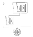
図2は、複数のプロセッサーによってロボットの制御装置が構成される一例を示す概念図である。この例では、ロボット100及びその制御装置200の他に、パーソナルコンピューター400,410と、LANなどのネットワーク環境を介して提供されるクラウドサービス500とが描かれている。パーソナルコンピューター400,410は、それぞれプロセッサーとメモリーとを含んでいる。また、クラウドサービス500においてもプロセッサーとメモリーを利用可能である。これらの複数のプロセッサーの一部又は全部を利用して、ロボット100の制御装置を実現することが可能である。
FIG. 2 is a conceptual diagram showing an example in which a robot control device is configured by a plurality of processors. In this example, in addition to the
図3は、複数のプロセッサーによってロボットの制御装置が構成される他の例を示す概念図である。この例では、ロボット100の制御装置200が、ロボット100の中に格納されている点が図2と異なる。この例においても、複数のプロセッサーの一部又は全部を利用して、ロボット100の制御装置を実現することが可能である。
FIG. 3 is a conceptual diagram showing another example in which a robot control device is configured by a plurality of processors. This example differs from FIG. 2 in that the
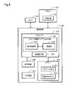
図4は、制御装置200の機能を示すブロック図である。制御装置200は、プロセッサー210とメモリー220と表示装置260と入力装置270とを備えている。メモリー220は、メインメモリーと不揮発性メモリーとを含む。プロセッサー210は、メモリー220に予め格納されたプログラム命令222を実行することにより、ロボット制御プログラム作成部240と制御実行部250の機能を実現する。ロボット制御プログラム作成部240は、表示制御部242と変換部244を含んでいる。表示制御部242は、ロボット100の作業の動作フローを作成するための入力画面(後述)を表示装置260に表示させる。変換部244は、入力画面で作成された動作フローを制御プログラム224に変換する。変換された制御プログラム224は、メモリー220に格納される。制御プログラム224は、機械語などの低級言語で記述されていてもよく、或いは、ロボット言語などの高級言語で記述されていてもよい。制御実行部250は、こうして作成された制御プログラム224を実行することによって、作業の動作をロボット100に実行させる。入力装置270は、キーボードやマウスなどの入力デバイスであり、教示者による入力や設定が入力装置270を用いて行われる。なお、ロボット制御プログラム作成部240と制御実行部250の機能の一部又は全部をハ―ドウェア回路で実現しても良い。ロボット制御プログラム作成部240の機能については更に後述する。
FIG. 4 is a block diagram showing the functions of the
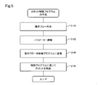
図5は、ロボット制御プログラムの作成手順を示すフローチャートであり、図6A~図6Dは、その手順の説明図である。図5の処理は、教示者がロボット制御プログラム作成部240を実現するアプリケーションプログラムを起動することによって開始される。
FIG. 5 is a flowchart showing a procedure for creating a robot control program, and FIGS. 6A to 6D are explanatory views of the procedure. The process of FIG. 5 is started by the instructor activating the application program that realizes the robot control
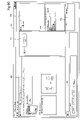
図6Aは、ロボット制御プログラム作成部240が起動すると表示制御部242が表示装置260に表示するウィンドウW1の一例を示している。このウィンドウW1は、1つ以上の動作を含む作業の動作フローを作成するための入力画面に相当する。ウィンドウW1は、以下の領域を含んでいる。
(1)メインビュー領域MV:後述する動作オブジェクト及び条件分岐オフジェクトの選択肢や、制御プログラムの実行結果、トラブルシュート(問題点の対策案)などを表示する領域である。
(2)動作フロー作成領域FL:複数のオブジェクトがグラフィカルに配置された動作フローを編集可能に表示する領域である。なお、動作フローで表される作業を「シーケンス」とも呼ぶ。
(3)シーケンス表示領域SQ:シーケンスのツリー構造を表示する領域である。
(4)パラメーター設定領域PR:作業全体に関する作業パラメーターや、個々の動作に関する動作パラメーターの設定を行うための領域である。
(5)結果領域RS:制御プログラムの実行結果を表示する領域である。
(6)実行指示領域RN:制御プログラムの実行を指示するための領域である。
FIG. 6A shows an example of the window W1 displayed on the
(1) Main view area MV: An area for displaying operation objects and conditional branch object options described later, control program execution results, troubleshooting (problem countermeasures), and the like.
(2) Operation flow creation area FL: An area in which an operation flow in which a plurality of objects are arranged graphically is displayed in an editable manner. The work represented by the operation flow is also called a "sequence".
(3) Sequence display area SQ: An area for displaying the tree structure of the sequence.
(4) Parameter setting area PR: An area for setting work parameters related to the entire work and operation parameters related to individual operations.
(5) Result area RS: An area for displaying the execution result of the control program.
(6) Execution instruction area RN: An area for instructing the execution of the control program.
図6Aの例では、ウィンドウW1内の複数の領域は、異なるフレームとして分割されているが、フレームに分割されていなくても良い。ウィンドウW1の左上には、作業の制御プログラムの作成手順の開始を指示するためのボタンBT1が設けられている。教示者がボタンBT1を押すと、図5のステップS110を開始するための入力画面が表示制御部242によって表示装置260に表示される。なお、本明細書では、教示者が、作業パラメーターを入力画面のボックスやフィールドに入力することを「入力する」と言い、教示者によって入力されたパラメーターを受け付けて内部の値を変更することを「設定する」と言う。
In the example of FIG. 6A, the plurality of regions in the window W1 are divided into different frames, but they do not have to be divided into frames. At the upper left of the window W1, a button BT1 for instructing the start of a procedure for creating a work control program is provided. When the instructor presses the button BT1, the input screen for starting step S110 in FIG. 5 is displayed on the
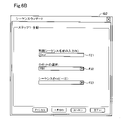
図6Bは、ステップS110を開始するための入力画面としてのウィンドウW2の一例を示している。このウィンドウW2は、以下の領域を含んでいる。
(1)シーケンス名設定領域F21:新たなシーケンスの名称を設定するための領域である。図6Bの例では、シーケンス名が「Seq1」と入力されている。
(2)ロボット選択領域F22:使用するロボットのタイプを複数の選択肢から選択するための領域である。図6Bの例では、「RB1」というタイプのロボットが選択されている。
(3)シーケンスコピー指示領域F23:既に作成済みのシーケンスをコピーすることを指定するための領域である。この領域には、例えば、予めメモリー220内に登録されている複数のシーケンスのシーケンス名がプルダウンメニューとして表示される。シーケンスコピーを使用する場合には、図6Cで説明する設定は不要となり、後述する図6Dの画面に移行する。
FIG. 6B shows an example of the window W2 as an input screen for starting step S110. This window W2 includes the following areas.
(1) Sequence name setting area F21: An area for setting a new sequence name. In the example of FIG. 6B, the sequence name is input as "Seq1".
(2) Robot selection area F22: An area for selecting the type of robot to be used from a plurality of options. In the example of FIG. 6B, a robot of the type "RB1" is selected.
(3) Sequence copy instruction area F23: An area for designating to copy a sequence that has already been created. In this area, for example, sequence names of a plurality of sequences registered in advance in the
本実施形態では、シーケンスコピーを使用せずに図6Cの画面に進む。すなわち、図6Bにおいて、教示者がシーケンスコピー指示領域F23の入力を行うこと無く「次へ」ボタンを押すと、表示装置260の表示内容が図6Cに示すウィンドウW1に変更される。
In this embodiment, the process proceeds to the screen of FIG. 6C without using the sequence copy. That is, in FIG. 6B, when the instructor presses the “Next” button without inputting the sequence copy instruction area F23, the display content of the
図6Cは、図6Aに示したウィンドウW1において、動作フローの作成を開始する状態を示している。ウィンドウW1の各領域には以下のような内容が表示される。
(1)メインビュー領域MV:
動作フローを構成する動作や条件分岐の分類を示す複数のカテゴリーと、各カテゴリーに属するオブジェクトの名称及びアイコンと、オブジェクトの内容の説明と、オブジェクトの概要を示す図とが表示される。メインビュー領域MVに表示されたオブジェクトは、ドラッグアンドドロップ等の操作によって動作フロー作成領域FL内の動作フローに任意に追加可能である。
(2)動作フロー作成領域FL:
1つ以上のオブジェクトがグラフィカルに配置された動作フローが編集可能に表示される。図6Cに示すように、動作フローの作成の開始時には、シーケンスのラベルを示すシーケンスブロックSB1のみが動作フロー作成領域FL内に配置される。
(3)シーケンス表示領域SQ:
動作フロー作成領域FLに表示されたシーケンスのツリー構造が表示される。
(4)パラメーター設定領域PR:
動作フロー作成領域FLに配置されたブロックのいずれかが選択されると、選択されたブロックに対するパラメーターが表示される。
FIG. 6C shows a state in which the creation of the operation flow is started in the window W1 shown in FIG. 6A. The following contents are displayed in each area of the window W1.
(1) Main view area MV:
A plurality of categories showing the classifications of operations and conditional branches constituting the operation flow, names and icons of objects belonging to each category, explanations of the contents of the objects, and a diagram showing an outline of the objects are displayed. The object displayed in the main view area MV can be arbitrarily added to the operation flow in the operation flow creation area FL by an operation such as drag and drop.
(2) Operation flow creation area FL:
The operation flow in which one or more objects are arranged graphically is displayed in an editable manner. As shown in FIG. 6C, at the start of creating an operation flow, only the sequence block SB1 indicating the label of the sequence is arranged in the operation flow creation area FL.
(3) Sequence display area SQ:
The tree structure of the sequence displayed in the operation flow creation area FL is displayed.
(4) Parameter setting area PR:
When any of the blocks placed in the operation flow creation area FL is selected, the parameters for the selected block are displayed.
図6Dは、ウィンドウW1の動作フロー作成領域FL内に、教示者が動作フローを作成した状態を示している。この例では、シーケンスブロックSB1の後に、接触オブジェクトOB1と、脱力オブジェクトOB2と、押付け探りオブジェクトOB3と、押付けオブジェクトOB4のブロックがこの順に配置されている。各オブジェクトのブロックの中には、そのオブジェクトの名称が表示される。4つのオブジェクトOB1~OB4はすべて動作オブジェクトであるが、条件分岐オブジェクトを配置することも可能である。条件分岐オブジェクトとは、予め定められた条件が成立するか否かに応じて、その進行先が切り換えられるオブジェクトを意味する。動作のカテゴリーと動作オブジェクトについては更に後述する。動作フローには、メインビュー領域MVに表示されたオブジェクトを任意に追加可能であり、また、動作フロー中の任意のオブジェクトを削除することも可能である。 FIG. 6D shows a state in which the instructor creates an operation flow in the operation flow creation area FL of the window W1. In this example, after the sequence block SB1, the contact object OB1, the weakening object OB2, the pressing search object OB3, and the pressing object OB4 are arranged in this order. The name of the object is displayed in the block of each object. All four objects OB1 to OB4 are operation objects, but it is also possible to arrange conditional branch objects. The conditional branch object means an object whose progress destination is switched depending on whether or not a predetermined condition is satisfied. The action categories and action objects will be described later. Objects displayed in the main view area MV can be arbitrarily added to the operation flow, and arbitrary objects in the operation flow can be deleted.
図6Dにおいて、動作フロー作成領域FLに配置されたブロックSB1,OB1~OB4のいずれかが選択されると、選択されたブロックに対するパラメーターがパラメーター設定領域PRに表示される。例えば、シーケンスブロックSB1が選択されると、シーケンス全体に関する作業パラメーターが表示される。また、オブジェクトのブロックOB1~OB4のいずれかが選択されると、そのオブジェクトに関するパラメーターが表示される。図6Dの例では、接触オブジェクトOB1に関するパラメーターが表示されている。これらのパラメーターは、必要に応じて変更される。 In FIG. 6D, when any of the blocks SB1 and OB1 to OB4 arranged in the operation flow creation area FL is selected, the parameters for the selected block are displayed in the parameter setting area PR. For example, when the sequence block SB1 is selected, working parameters for the entire sequence are displayed. Further, when any of the blocks OB1 to OB4 of the object is selected, the parameters related to the object are displayed. In the example of FIG. 6D, the parameters related to the contact object OB1 are displayed. These parameters are changed as needed.
図7は、動作フローを構成する際に利用可能な複数の動作オブジェクトの例を示しており、図8A~図8Dは幾つかの動作オブジェクトの動作の概要を示している。複数の動作オブジェクトは、例えば以下の4つに分類可能である。これらは、いずれも力制御を伴う動作である。 FIG. 7 shows an example of a plurality of motion objects that can be used when configuring the motion flow, and FIGS. 8A to 8D show an outline of the motion of some motion objects. A plurality of motion objects can be classified into the following four, for example. All of these are operations involving force control.
<分類1:接触>指定方向に移動して、反力を受けたら停止する動作である。
接触動作の分類は、接触オブジェクトを含む。図8Aに示すように、接触オブジェクトでは、エンドエフェクター140で保持したワークWKaを指定方向DDに移動させ、力検出器130で反力を検出した時にエンドエフェクター140を停止させる。なお、図8Aに示したワークWKa,WKbは、図1に示したワークWK1,WK2とは無関係であり、動作の概要を説明するための仮想的なワークである。この点は、後述する図8B~図8Dも同様である。
<Category 1: Contact> This is an operation that moves in a specified direction and stops when a reaction force is received.
The contact motion classification includes contact objects. As shown in FIG. 8A, in the contact object, the work WKa held by the
<分類2:倣い>指定軸の力が0になる状態を維持する動作である。
倣い動作の分類は、以下の3種類の動作オブジェクトを含む。
(a)脱力オブジェクト:指定軸の力が0になるように倣う動作である。
図8Bに示すように、脱力オブジェクトでは、指定軸の力が0になるように倣う動作が実行される。図8Bの例では、ワークWKa,WKb間のz軸方向の力が0でないときに-z方向にエンドエフェクター140を戻すことにより、力検出器130で検出されるz軸方向の力を0にしている。
(b)倣い移動オブジェクト:指定軸の力を0にするように倣いながら指定軌道を動く動作である。
(c)面合わせオブジェクト:指定方向に角度を倣いながら押し付けて、面と面とを合わせる動作である。
<Category 2: Copying> This is an operation of maintaining a state in which the force of the designated axis becomes 0.
The classification of imitation motion includes the following three types of motion objects.
(A) Weakness object: This is an operation that imitates the force of the designated axis to be zero.
As shown in FIG. 8B, in the weakening object, an operation of imitating the force of the designated axis becomes 0 is executed. In the example of FIG. 8B, when the force in the z-axis direction between the workpieces WKa and WKb is not 0, the
(B) Copying movement object: This is an operation of moving in a designated trajectory while copying so that the force of the designated axis becomes 0.
(C) Face-to-face object: This is an operation of aligning faces with each other by pressing them in a designated direction while tracing an angle.
<分類3:探り>指定方向の力が0となる位置を探る動作である。
探り動作の分類は、以下の2種類の動作オブジェクトを含む。
(a)押付け探りオブジェクト:押付ながら指定された軌跡で探って穴を見つける動作である。
図8Cに示すように、押付け探りオブジェクトでは、エンドエフェクター140で保持したワークWKaを指定方向に押付けながら、指定方向の力がゼロとなる位置を探り、穴Hbの位置で停止させる。探りの軌跡としては、直線軌跡や螺旋軌跡などの複数の候補の中から1つの軌跡を選択することが可能である。
(b)接触探りオブジェクト:接触動作を繰り返して穴を見つける動作である。
<Category 3: Search> This is an operation to search for a position where the force in the specified direction becomes 0.
The search motion classification includes the following two types of motion objects.
(A) Pushing search object: This is an operation of finding a hole by searching on a designated trajectory while pushing.
As shown in FIG. 8C, in the pressing search object, the work WKa held by the
(B) Contact search object: An operation of repeatedly contacting to find a hole.
<分類4:押付け>指定方向に指定の力で押し付ける動作である。
押付け動作の分類は、以下の2種類の動作オブジェクトを含む。
(a)押付け(単純押付け)オブジェクト:指定方向に指定の力で押し付ける動作である。この動作では、他の指定軸については「倣う」動作を実行させることも可能である。
(b)押付け移動オブジェクト:指定方向に指定の力で押し付けながら移動する動作である。この動作では、他の指定軸については「倣う」動作を実行させることも可能である。図8Dに示すように、押付け移動オブジェクトでは、指定方向DDにエンドエフェクター140を移動させて指定の力で押付け、その後、指定の力での押付けを維持しながら(すなわち、倣いながら)指定方向と異なる方向に移動する。図8Dの例では、エンドエフェクター140で保持したワークWKaをワークWKbの穴Hbに挿入する動作が、押付け移動によって実行されている。
<Category 4: Pressing> This is an operation of pressing in a specified direction with a specified force.
The classification of pressing motion includes the following two types of motion objects.
(A) Pressing (simple pressing) object: This is an operation of pressing in a specified direction with a specified force. In this operation, it is also possible to execute an operation of "imitating" for other designated axes.
(B) Pushing movement object: It is an operation of moving while pushing in a designated direction with a designated force. In this operation, it is also possible to execute an operation of "imitating" for other designated axes. As shown in FIG. 8D, in the pressing movement object, the
図6Dに示した動作オブジェクトOB1~OB4に関しては、動作の終了条件を定義するパラメーターと、動作の成否判定条件を定義するパラメーターとを設定可能である。例えば、接触オブジェクトOB1に関しては以下のパラメーターを設定できる。 For the operation objects OB1 to OB4 shown in FIG. 6D, a parameter that defines the operation end condition and a parameter that defines the operation success / failure determination condition can be set. For example, the following parameters can be set for the contact object OB1.
<接触オブジェクトOB1のパラメーター>
(1)動作を定義する動作パラメーターの例
・接触方向:-Z方向(接触方向は、作業パラメーターとして設定された嵌合方向から自動的に設定される。)
・接触予定距離:10mm
・動作速度:5mm/s
・接触時の力制御ゲイン:1.0
(2)終了条件の例
・目標力:5N(5Nを超えると動作を停止する)
(3)成否判定条件の例
・成否判定条件:タイムアウト時間=10秒(タイムアウト時間までに終了条件を満たした場合には動作が成功したものと判定し、終了条件を満たさなかった場合には動作が失敗したものと判定する。)
・失敗時動作:シーケンスを継続(動作が失敗したと判定された場合にどのように進めるかを指定する。シーケンスの継続又はシーケンスの終了を指定可能である。)
<Parameter of contact object OB1>
(1) Examples of operation parameters that define the operation-Contact direction: -Z direction (The contact direction is automatically set from the fitting direction set as the work parameter.)
・ Scheduled contact distance: 10 mm
・ Operating speed: 5 mm / s
・ Force control gain at the time of contact: 1.0
(2) Example of end condition ・ Target force: 5N (operation stops when 5N is exceeded)
(3) Examples of success / failure judgment conditions-Success / failure judgment conditions: Time-out time = 10 seconds (If the end condition is satisfied by the time-out time, it is judged that the operation was successful, and if the end condition is not satisfied, the operation is performed. Is determined to have failed.)
-Operation at failure: Continue the sequence (specify how to proceed when it is determined that the operation has failed. It is possible to specify the continuation of the sequence or the end of the sequence.)
これらの例から理解できるように、本実施形態では、動作を定義するパラメーターと、動作の終了条件を定義するパラメーターと、動作の成否判定条件を定義するパラメーターとを設定可能なパラメーター設定領域PRを表示可能なので、動作の終了や成功/失敗の判定を含む制御プログラムを容易に作成することが可能である。なお、動作の終了条件を定義するパラメーターと、動作の成否判定条件を定義するパラメーターとのうちの一方又は両方の設定が行えない形態としてもよい。 As can be understood from these examples, in the present embodiment, a parameter setting area PR in which parameters that define the operation, parameters that define the end condition of the operation, and parameters that define the success / failure judgment condition of the operation can be set is provided. Since it can be displayed, it is possible to easily create a control program including the end of operation and the determination of success / failure. In addition, one or both of the parameter defining the end condition of the operation and the parameter defining the success / failure determination condition of the operation may not be set.
なお、動作パラメーターの終了条件又は成否判定条件は、力検出器130で測定される力の周波数に基づいて判定を実行する条件を含むように設定することも可能である。
The end condition or success / failure determination condition of the operation parameter can be set to include a condition for executing the determination based on the frequency of the force measured by the
図9は、力検出器130で測定される力Fの変化の一例を示している。この例では、動作開始から0.5秒後以降の期間PPにおいて、力Fが振動している。このような振動は、周辺装置(例えばコンベアが動作していること)の影響である可能性がある。従って、ロボット100の動作が周辺装置の影響を受けることを回避するために、制御装置200が力Fの時間変化の周波数分析を実行して、予め指定した周波数のパワースペクトルが閾値以下又は閾値以上になることを検知したことを終了条件又は成否判定条件の一部として使用してもよい。図9の例では、期間PPが経過した後、すなわち、予め指定した周波数のパワースペクトルが閾値以下になった後に、動作が終了する旨の判定、又は動作の成功又は失敗の判定を行うことができる。こうすれば、力検出器130で測定される力の周波数に基づいて判定する条件を使用するので、図9のように動作によって振動が発生する場合にも、動作の終了の有無の判定や、動作の成否の判定をより正しく行うことが可能である。
FIG. 9 shows an example of the change in the force F measured by the
図6Dに示したように作業の動作フローが作成されると、この動作フローに従ってロボット100に作業を実行させることが可能である。例えば、図6Dの実行指示領域RN内にある「実行」ボタンを教示者が押すと、変換部244(図4)が動作フローを制御プログラムに変換し、制御実行部250がその制御プログラムを実行することによってロボット100に作業を実行させる。これは、制御プログラムの試行に相当する。
When the operation flow of the work is created as shown in FIG. 6D, it is possible to cause the
図10Aは、動作フローに従って作業を実行した結果を示す画面の一例を示している。
メインビュー領域MV内には、動作フローの実行時に力検出器130で検出された複数の力のうちから、X軸方向の力FxとX軸回りのトルクTxの時間変化が表示されている。なお、メインビュー領域MVには、力検出器130で検出された複数の力の中の任意の1つ以上の力の時間変化を選択して表示することが可能である。また、TCPの実測位置の時間変化や、TCPの目標位置と実測位置の偏差の時間変化をメインビュー領域MVに表示することも可能である。メインビュー領域MV内の結果表示の期間は、動作フロー中の任意の1つの動作オブジェクトの動作期間とすることも可能であり、また、実行開始から停止までの全期間とすることも可能である。例えば、動作フロー作成領域FL内で任意の動作オブジェクトを選択すると、その動作オブジェクトの動作期間の実行結果が表示される。また、シーケンスブロックSB1を選択すると、実行開始から停止までの全期間の結果が表示される。なお、メインビュー領域MV内の結果表示の期間は、複数の連続する動作オブジェクトに亘る動作期間としてもよい。結果領域RSにも、制御プログラムの実行結果の一部の情報が表示される。例えば、任意の動作オブジェクトについて、動作の終了状態(成功又は失敗)や、動作に要した時間、動作終了時の力、及び、動作終了時の位置などを結果領域RS内に表示可能である。なお、メインビュー領域MVには、図10Aに示したもの以外の種々の結果を表示できるようにしてもよい。例えば、ロボットの速度や各関節の角度などのロボットに関わる情報を表示してもよい。
FIG. 10A shows an example of a screen showing the result of executing the work according to the operation flow.
In the main view area MV, the time change of the force Fx in the X-axis direction and the torque Tx around the X-axis is displayed from among the plurality of forces detected by the
ウィンドウW1は、更に、実行した結果のデータを所望の場所に保存するためのフィールドやボタンを有するように構成されていることが好ましい。実行結果のデータを保存できるようにすれば、後述する調整において、過去のデータと見比べることが可能となる。なお、データの保存先は、ロボット制御装置200内でもよく、ロボット制御装置200に接続されたコンピューターやクラウドでもよい。また、データ形式は、データベースでもよく、ファイル形式でもよい。
The window W1 is further preferably configured to have fields and buttons for storing the data of the result of the execution in a desired location. If the execution result data can be saved, it can be compared with the past data in the adjustment described later. The data storage destination may be in the
教示者は、制御プログラムの実行結果を観察し、必要に応じて個々のオブジェクトのパラメーターを調整することが可能である(図5のステップS120)。この調整は、動作フロー作成領域FL内のオブジェクトOB1~OB4の任意の1つを選択した状態において、パラメーター設定領域PRに表示されるオブジェクトのパラメーターを変更することによって行うことができる。具体例として、例えば接触動作において接触したときの力が過度に大きな場合には、接触動作における速度を低下させるように接触オブジェクトのパラメーターが調整される。 The teacher can observe the execution result of the control program and adjust the parameters of the individual objects as needed (step S120 in FIG. 5). This adjustment can be performed by changing the parameters of the objects displayed in the parameter setting area PR while any one of the objects OB1 to OB4 in the operation flow creation area FL is selected. As a specific example, for example, if the force at the time of contact in the contact motion is excessively large, the parameters of the contact object are adjusted so as to reduce the speed in the contact motion.
図10Bは、パラメーターの調整後に制御プログラムを再度実行した結果の例を示している。この例では、調整後の力Fnew,Tnewのピークが、調整前の力Fold,Toldのピークに比べて小さくなっている。このように、このウィンドウW1では、動作フロー作成領域FL内で生成された動作フローのオブジェクトのパラメーターの調整と、その動作フロ―に従った作業の試行とを行うことができるので、適切に動作する動作フローを容易に作成できる。なお、図10Aで説明したように、過去の実行結果のデータを保存しておいた場合には、過去のデータを表示することも可能となる。 FIG. 10B shows an example of the result of executing the control program again after adjusting the parameters. In this example, the peaks of the adjusted forces Fnew and Tnew are smaller than the peaks of the unadjusted forces Fold and Told. In this way, in this window W1, it is possible to adjust the parameters of the object of the operation flow generated in the operation flow creation area FL and to try the work according to the operation flow, so that the operation is appropriate. You can easily create an operation flow to be performed. As described with reference to FIG. 10A, when the data of the past execution result is saved, the past data can be displayed.
図11は、力制御動作の問題点の対策案を提示する画面の一例を示す説明図である。この入力画面W1は、制御プログラムの実行後に、メインビュー領域MVのトラブルシュートのタブを選択することによって表示される。この状態のメインビュー領域MVを「対策案提示領域TS」と呼ぶ。対策案提示領域TSには、動作フローを構成する複数の動作オブジェクトOB1~OB4の名称が動作フローに従って配列されており、実行結果で問題のあった動作オブジェクトについて、その問題点と対策案が表示される。動作オブジェクトに問題点が存在するか否かは、例えば、作業の試行においてその動作オブジェクトの終了条件や成否判定条件が満たされていたか否かに応じて判定することができる。なお、「問題点」とは、ロボットの動作が予め設定した所定の動作でないことを意味する。 FIG. 11 is an explanatory diagram showing an example of a screen for presenting a countermeasure plan for a problem of force control operation. This input screen W1 is displayed by selecting the troubleshooting tab of the main view area MV after executing the control program. The main view area MV in this state is referred to as a "countermeasure proposal presentation area TS". In the countermeasure proposal presentation area TS, the names of a plurality of operation objects OB1 to OB4 constituting the operation flow are arranged according to the operation flow, and the problems and countermeasures are displayed for the operation objects having a problem in the execution result. Will be done. Whether or not there is a problem in the motion object can be determined, for example, depending on whether or not the end condition and the success / failure determination condition of the motion object are satisfied in the trial of the work. The "problem" means that the operation of the robot is not a predetermined operation set in advance.
対策案提示領域TSには、動作フロー作成領域FLにおいて教示者が選択した1つの動作オブジェクトのみを表示するようにしてもよい。また、メインビュー領域MVのトラブルシュートのタブを選択した後に対策案を提示する代わりに、表示制御部242が制御プログラムの実行結果から問題点を自動的に検出し、検出した問題点に対する対策案を提示するようにしてもよい。「問題点に対する対策案」は、「予め設定した所定の動作を実現するための対策案」と呼ぶことも可能である。 In the countermeasure proposal presentation area TS, only one operation object selected by the instructor in the operation flow creation area FL may be displayed. Further, instead of presenting a countermeasure plan after selecting the troubleshooting tab of the main view area MV, the display control unit 242 automatically detects the problem from the execution result of the control program, and the countermeasure plan for the detected problem is detected. May be presented. The "countermeasure plan for the problem" can also be called a "countermeasure plan for realizing a predetermined operation set in advance".
図12に拡大して示すように、この例では、対策案提示領域TS内に接触オブジェクトに関して以下の5つの項目について問題点があることが提示されている。
・「接触せずにタイムアウトする」
・「時間がかかる」
・「接触時の力が大きい」
・「動かしたい方向に動かない」
・「接触前に接触と誤判定する」
これらの5つの項目は、「予め設定した所定の動作では無いことを示す項目」に相当する。
As shown in an enlarged manner in FIG. 12, in this example, it is presented that there are problems with the following five items regarding the contact object in the countermeasure proposal presentation area TS.
・ "Time out without contact"
·"time consuming"
・ "The force at the time of contact is large"
・ "Does not move in the direction you want to move"
・ "Misjudgment as contact before contact"
These five items correspond to "items indicating that the operation is not a preset predetermined operation".
また、図12では、「接触せずにタイムアウトする」という問題点が教示者によって選択されており、その問題点に対する対策案として、「1.開始位置を確認する」、「2.動作のパラメーターを確認する」の対策案が提示されている。「2.動作のパラメーターを確認する」の対策案には、その動作のパラメーターを調整する画面に切り替えるためのボタンBT2が表示されている。 Further, in FIG. 12, the problem of "time-out without contact" is selected by the instructor, and as countermeasures for the problem, "1. Confirm the start position" and "2. Operation parameters". The countermeasure plan of "confirm" is presented. In the countermeasure plan of "2. Checking the operation parameters", the button BT2 for switching to the screen for adjusting the operation parameters is displayed.
図13は、図12のボタンBT2を押した場合に表示される対策案提示領域TSの例を示している。この対策案提示領域TSは、目標値フィールドTFと、パラメーター設定値テーブルPTと、を含んでいる。また、問題点を解消するためのパラメーターの変更の方向を説明する説明文として、「目標力を大きくすると速度が速くなります」及び「力制御ゲインを小さくすると速度が速くなります」という文章が表示されている。 FIG. 13 shows an example of a countermeasure proposal presentation area TS displayed when the button BT2 of FIG. 12 is pressed. This countermeasure proposal area TS includes a target value field TF and a parameter setting value table PT. In addition, as explanations explaining the direction of parameter changes to solve the problem, the sentences "Increasing the target force increases the speed" and "Reducing the force control gain increases the speed". It is displayed.
目標値フィールドTFは、その動作オブジェクトのパラメーターでは無いが、後述する第2特性値CV2を算出するために設定される目標値を入力するフィールドである。この例では、接触動作における目標移動距離が、目標値フィールドTFとして表示されている。 The target value field TF is not a parameter of the operation object, but is a field for inputting a target value set for calculating the second characteristic value CV2 described later. In this example, the target movement distance in the contact operation is displayed as the target value field TF.
パラメーター設定値テーブルPTには、その動作オブジェクトのパラメーターの名称と、その現在設定値と、推奨設定値とが表示される。パラメーター設定値テーブルPTのパラメーターとしては、その動作オブジェクトの複数のパラメーターのうち、その動作オブジェクトの問題点に関連するパラメーターのみを提示することが好ましい。「問題点に関連するパラメーター」とは、そのパラメーターを調整することによって問題点を解消できる可能性のあるパラメーターを意味する。図13の例では、接触オブジェクトの問題点に関連するパラメーターとして、「目標力」と「力制御ゲイン」と「タイムアウト時間」の3つが提示されている。パラメーター設定値テーブルPTに、その動作オブジェクトの問題点に関連するパラメーターのみを対策案として提示すれば、教示者がその動作オブジェクトの問題点を容易に解消できる。 In the parameter setting value table PT, the name of the parameter of the operation object, the current setting value, and the recommended setting value are displayed. As the parameters of the parameter setting value table PT, it is preferable to present only the parameters related to the problem of the operation object among the plurality of parameters of the operation object. "Parameters related to a problem" means a parameter that may be solved by adjusting the parameter. In the example of FIG. 13, three parameters, "target force", "force control gain", and "timeout time", are presented as parameters related to the problem of the contact object. If only the parameters related to the problem of the operation object are presented as a countermeasure in the parameter setting value table PT, the teacher can easily solve the problem of the operation object.
パラメーター設定値テーブルPTには、更に、動作オブジェクトのパラメーターから予想される特性値も表示される。ここでは、パラメーターから予想される特性値として、「予想移動距離」と「予想移動速度」と「予想接触時間」の3つの特性値が例示されている。これらのうち、「予想移動距離」と「予想移動速度」は、接触オブジェクトのパラメーターのみから予想される特性値である。このように、動作オブジェクトのパラメーターのみから予想される特性値を「第1特性値CV1」と呼ぶ。なお、「第1特性値CV1」を、「パラメーターの推奨設定値から算出した第1特性値」とも呼ぶ。一方、「予想接触時間」は、接触オブジェクトのパラメーターと、目標値フィールドTFに入力される目標値(図13の例では目標移動距離)とから予想される特性値である。このように、目標値フィールドTFに入力される目標値と動作オブジェクトのパラメーターの設定値から予想される特性値を「第2特性値CV2」と呼ぶ。なお、「第2特性値CV2」を、「目標値とパラメーターの推奨設定値から算出した第2特性値」とも呼ぶ。但し、図13の例では、目標値フィールドTFに目標値が入力されていないので、第2特性値CV2である予想接触時間の値は表示されていない。 In the parameter setting value table PT, the characteristic value expected from the parameter of the operation object is also displayed. Here, as characteristic values expected from the parameters, three characteristic values of "expected movement distance", "expected movement speed", and "expected contact time" are exemplified. Of these, the "expected movement distance" and the "expected movement speed" are characteristic values expected only from the parameters of the contact object. In this way, the characteristic value expected only from the parameters of the operating object is called the "first characteristic value CV1". The "first characteristic value CV1" is also referred to as a "first characteristic value calculated from the recommended setting values of the parameters". On the other hand, the "expected contact time" is a characteristic value expected from the parameters of the contact object and the target value (target movement distance in the example of FIG. 13) input to the target value field TF. In this way, the characteristic value expected from the target value input to the target value field TF and the set value of the parameter of the operation object is called "second characteristic value CV2". The "second characteristic value CV2" is also referred to as a "second characteristic value calculated from the target value and the recommended set value of the parameter". However, in the example of FIG. 13, since the target value is not input to the target value field TF, the value of the expected contact time, which is the second characteristic value CV2, is not displayed.
パラメーター設定値テーブルPTに表示されるパラメーターの推奨設定値は、その動作の問題点を解消できる可能性がある設定値である。この推奨設定値は、制御プログラムの実行結果に応じて、ロボット制御プログラム作成部240によって決定される。
Parameter setting value The recommended setting value of the parameter displayed in the table PT is a setting value which may solve the problem of the operation. This recommended setting value is determined by the robot control
対策案提示領域TSには、推奨設定値を受け入れることを示すボタンBT3と、新規設定値を入力する画面に切り換えるためのボタンBT4とが含まれている。ボタンBT3を押すと、推奨設定値が採用され、その後、実行指示領域RN(図6D)内の「実行」ボタンを教示者が押すと、推奨設定値を用いて動作フローが再度実行される。 The countermeasure proposal presentation area TS includes a button BT3 indicating that the recommended setting value is accepted, and a button BT4 for switching to a screen for inputting a new setting value. When the button BT3 is pressed, the recommended set value is adopted, and then when the instructor presses the "execute" button in the execution instruction area RN (FIG. 6D), the operation flow is executed again using the recommended set value.
図14は、図13において目標値フィールドTFに目標値が入力された後に表示される対策案提示領域TSを示している。この例では、目標値フィールドTFに入力された目標値と動作オブジェクトの設定値とから決まる第2特性値CV2である予想接触時間の値が表示されている。なお、動作オブジェクトのパラメーターのみから決まる第1特性値CV1のうち、「予想移動距離」は、目標値フィールドTFに入力された目標値と重複するので表示されていないが、目標値と同じ値を表示してもよい。 FIG. 14 shows a countermeasure proposal presentation area TS displayed after the target value is input to the target value field TF in FIG. 13. In this example, the value of the expected contact time, which is the second characteristic value CV2 determined from the target value input to the target value field TF and the set value of the motion object, is displayed. Of the first characteristic value CV1 determined only by the parameters of the motion object, the "expected movement distance" is not displayed because it overlaps with the target value input in the target value field TF, but the same value as the target value is used. It may be displayed.
このように、対策案提示領域TSに第1特性値や第2特性値CV2を表示するようにすれば、教示者がこれらの特性値を見て力制御動作の問題点を容易に解消することが可能である。 In this way, if the first characteristic value and the second characteristic value CV2 are displayed in the countermeasure proposal presentation area TS, the instructor can easily solve the problem of the force control operation by looking at these characteristic values. Is possible.
図15は、図13において新規設定値を入力する画面に切り換えるためのボタンBT4が押された後に表示される対策案提示領域TSを示している。この例では、パラメーターの現在設定値と推奨設定値に加えて、パラメーターの新規設定値を入力する設定値フィールドSFが表示されている。この設定値フィールドSFの値は、教示者が任意に変更可能である。推奨設定値と新規設定値の下方には、その設定値を受け入れることを示すボタンBT3a,BT3bが表示されている。教示者は、これらのボタンBT3a,BT3bのいずれかを押すことによって、推奨設定値か新規設定値のいずれかを採用することが可能である。従って、教示者が適切な設定値を任意に設定して力制御動作の問題点を容易に解消することが可能である。なお、パラメーターの新規設定値を入力する設定値フィールドSFを表示する際に、パラメーターの現在設定値と推奨設定値を表示しないようにしてもよい。 FIG. 15 shows a countermeasure proposal presentation area TS displayed after the button BT4 for switching to the screen for inputting a new setting value is pressed in FIG. 13. In this example, in addition to the current setting value and the recommended setting value of the parameter, the setting value field SF for inputting the new setting value of the parameter is displayed. The value of this set value field SF can be arbitrarily changed by the teacher. Below the recommended set value and the new set value, buttons BT3a and BT3b indicating that the set value is accepted are displayed. The teacher can adopt either the recommended setting value or the new setting value by pressing any of these buttons BT3a and BT3b. Therefore, it is possible for the instructor to arbitrarily set an appropriate set value and easily solve the problem of the force control operation. When displaying the setting value field SF for inputting the new setting value of the parameter, the current setting value and the recommended setting value of the parameter may not be displayed.
なお、対策案提示領域TSにおいてパラメーターの新規設定値を入力する代わりに、図1に示したパラメーター設定領域PRにおいてパラメーターの新規設定値を入力するようにしてもよい。 Instead of inputting the new parameter setting value in the countermeasure proposal presentation area TS, the parameter new setting value may be input in the parameter setting area PR shown in FIG.
図16は、接触オブジェクトの「接触前に接触と誤判定する」という問題点に対する対策案を提示する対策案提示領域TSの例を示している。ここでは、問題点を解消するためのパラメーターの変更の方向を説明する説明文として、「力制御ゲインを大きくする」及び「目標力を大きくする」という2つの文章が表示されている。このように、問題点を解消するためのパラメーターの変更の方向を説明する説明文として、1つ又は複数の説明文を対策案提示領域TSに表示するようにすれば、教示者が問題点を解消する設定値をより容易に入力することが可能となる。 FIG. 16 shows an example of a countermeasure proposal presentation area TS that presents a countermeasure proposal for the problem of “misdetermining contact as contact before contact” of the contact object. Here, two sentences "increase the force control gain" and "increase the target force" are displayed as explanatory sentences explaining the direction of changing the parameters for solving the problem. In this way, if one or more explanatory texts are displayed in the countermeasure proposal presentation area TS as explanatory texts explaining the direction of changing the parameters for solving the problems, the instructor can solve the problems. It becomes possible to more easily input the setting value to be eliminated.
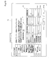
図17は、パラメーターの設定値を複数回試行した後に表示される対策案提示領域TSの例を示している。この例では、パラメーター設定値テーブルPTに、パラメーターの設定値の履歴が表示されている。具体的には、パラメーター設定値テーブルPTには、過去の設定値と、現在設定値と、推奨設定値と、新規設定値が表示されている。また、各設定値に対しては、設定値を受け入れることを示すボタンBT3a~BT3dが設けられている。従って、例えばボタンBT3bを押せば、過去に使用した設定値を再選択することが可能である。過去の設定値は1つに限らず、複数の過去の設定値を履歴として表示してもよい。 FIG. 17 shows an example of the countermeasure proposal presentation area TS displayed after the parameter setting values are tried a plurality of times. In this example, the history of the parameter setting values is displayed in the parameter setting value table PT. Specifically, the parameter setting value table PT displays the past setting value, the current setting value, the recommended setting value, and the new setting value. Further, for each set value, buttons BT3a to BT3d indicating that the set value is accepted are provided. Therefore, for example, by pressing the button BT3b, it is possible to reselect the set value used in the past. The past setting value is not limited to one, and a plurality of past setting values may be displayed as a history.
図17では、更に、過去の設定値と現在の設定値について、その設定値を用いた動作フローの実行結果を表示させるための結果表示ボタンBT4a,BT4bが設けられている。これらの結果表示ボタンBT4a,BT4bのいずれかを押すと、その設定値を用いた動作フローの実行結果が、前述した図10A又は図10Bに示したように、メインビュー領域MVに表示される。なお、このときに表示される実行結果としては、パラメーターの設定値の履歴に含まれる異なる設定値に対応する実行結果が識別可能な態様で表示されることが好ましい。こうすれば、教示者がパラメーターの設定値の履歴の中から、最もすぐれた実行結果を容易に選択できる。 Further, in FIG. 17, for the past set value and the current set value, result display buttons BT4a and BT4b for displaying the execution result of the operation flow using the set value are provided. When any of these result display buttons BT4a and BT4b is pressed, the execution result of the operation flow using the set value is displayed in the main view area MV as shown in FIG. 10A or FIG. 10B described above. As the execution result displayed at this time, it is preferable that the execution results corresponding to the different setting values included in the history of the parameter setting values are displayed in an identifiable manner. In this way, the teacher can easily select the best execution result from the history of the parameter setting values.
このように、図5のステップS120では、様々な方法でパラメーター調整を行うことが可能である。 As described above, in step S120 of FIG. 5, parameter adjustment can be performed by various methods.
こうして動作フローが完成すると、図5のステップS130において、教示者の指示に応じて変換部244が動作フローを制御プログラムに変換する。この指示は、例えば、動作フロー作成領域FLのコンテキストメニューから「制御プログラムの作成」を選択することによって行うことができる。なお、動作フローから制御プログラムへの変換と実行には、以下の3種類の方法いずれかを選択的に行えることが好ましい。
(1)動作フローを低級言語の制御プログラムに変換する。教示者は、変換された低級言語の制御プログラムを、自分で別個に記述した高級言語の制御プログラムから呼び出して実行する。この場合には、教示者が作業シーケンスを作成した後に、教示者が別個に記述する高級言語の制御プログラムの中で、例えば"FGRun シーケンス名"と記述することによって、そのシーケンスの制御プログラムが呼び出されて実行される。これは、最も基本的な実行方法である。
(2)動作フローを高級言語の制御プログラムに変換して、それを実行する。
(3)動作フローを低級言語の制御プログラムに変換して、それを直接実行する。
以下の説明では、主として上記(2)の方法で実行する場合を説明する。
When the operation flow is completed in this way, in step S130 of FIG. 5, the
(1) Convert the operation flow into a low-level language control program. The teacher calls and executes the converted low-level language control program from the high-level language control program described separately by himself / herself. In this case, after the teacher creates the work sequence, the control program of the sequence is called by writing, for example, "FGRun sequence name" in the control program of the high-level language described separately by the teacher. Is executed. This is the most basic way to do it.
(2) Convert the operation flow into a high-level language control program and execute it.
(3) Convert the operation flow into a low-level language control program and execute it directly.
In the following description, the case of executing by the method (2) above will be mainly described.
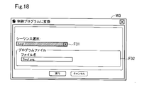
図18は、教示者の指示に応じて動作フローを制御プログラムに変換する際に表示される入力画面としてのウィンドウW3の一例を示している。このウィンドウW3は、制御プログラムに変換するシーケンス(すなわち動作フロー)を選択するシーケンス選択領域F31と、制御プログラムのファイル名を設定するプログラムファイル名設定領域F32とを含んでいる。なお、シーケンス選択領域F31は省略してもよい。なお、ウィンドウW3は、パラメーターの保存先などの情報を指定する領域を有するように構成されていてもよい。ウィンドウW3において「実行」ボタンを押すと、変換部244によって動作フローが制御プログラムに変換され、その制御プログラムがメモリー220内に格納される。
FIG. 18 shows an example of a window W3 as an input screen displayed when converting an operation flow into a control program according to an instruction of a teacher. This window W3 includes a sequence selection area F31 for selecting a sequence (that is, an operation flow) to be converted into a control program, and a program file name setting area F32 for setting a file name of the control program. The sequence selection area F31 may be omitted. The window W3 may be configured to have an area for designating information such as a parameter storage destination. When the "execute" button is pressed in the window W3, the operation flow is converted into a control program by the
図5のステップS140では、ステップS130で作成された制御プログラムに従って、ロボット制御装置200がロボットを制御し、ロボットに作業を実行させる。この作業は、製造ラインでロボット100の動作を確認する確認作業や、或いは、製造ラインで製品を製造するための本作業として実行可能である。
In step S140 of FIG. 5, the
以上のように、第1実施形態では、表示制御部242は、制御実行部250によって動作フローの制御プログラムが実行された後に、ロボット100の動作が予め設定した所定の動作でない場合に、予め設定した所定の動作を実現するための対策案を提示するので、その動作の問題点を解消して、正常に動作を実行させることが可能である。
As described above, in the first embodiment, the display control unit 242 is preset when the operation of the
また、第1実施形態では、動作フロー作成領域FLに動作オブジェクトと条件分岐オブジェクトとをグラフィカルに配置することによって、条件分岐を含む動作フローを容易に作成できるので、作業中の動作が失敗したときにそのリカバリーや終了処理を簡単に教示することが可能である。また、その動作フローがロボットの制御プログラムに変換されるので、制御プログラムを容易に作成することが可能である。 Further, in the first embodiment, by graphically arranging the operation object and the conditional branch object in the operation flow creation area FL, the operation flow including the conditional branch can be easily created, so that when the operation during work fails. It is possible to easily teach the recovery and termination processing. Moreover, since the operation flow is converted into the control program of the robot, it is possible to easily create the control program.
B. 他の実施形態:
本発明は、上述した実施形態に限られるものではなく、その趣旨を逸脱しない範囲において種々の形態で実現することができる。例えば、本発明は、以下の形態(aspect)によっても実現可能である。以下に記載した各形態中の技術的特徴に対応する上記実施形態中の技術的特徴は、本発明の課題の一部又は全部を解決するために、あるいは、本発明の効果の一部又は全部を達成するために、適宜、差し替えや、組み合わせを行うことが可能である。また、その技術的特徴が本明細書中に必須なものとして説明されていなければ、適宜、削除することが可能である。
B. Other embodiments:
The present invention is not limited to the above-described embodiment, and can be realized in various forms without departing from the spirit of the present invention. For example, the present invention can also be realized by the following aspect. The technical features in the above embodiments corresponding to the technical features in each of the embodiments described below are for solving some or all of the problems of the present invention, or part or all of the effects of the present invention. It is possible to replace or combine as appropriate to achieve the above. Further, if the technical feature is not described as essential in the present specification, it can be appropriately deleted.
(1)本発明の第1の形態によれば、力検出器を備えるロボットの作業の制御プログラムを作成するロボット制御装置が提供される。このロボット制御装置は、力制御動作を含む作業の動作フローを作成するための動作フロー作成領域を含む入力画面を表示装置に表示させる表示制御部と;作成された動作フローを制御プログラムに変換する変換部と;前記制御プログラムを実行して前記ロボットを制御する制御実行部と;を備える。前記表示制御部は、前記制御実行部によって前記制御プログラムが実行された後に、前記ロボットの動作が予め設定した所定の動作でない場合に、前記予め設定した所定の動作を実現するための対策案を提示する画面を前記表示装置に表示させるように構成されている。
このロボット制御装置によれば、制御実行部によって制御プログラムが実行された後に、表示制御部が予め設定した所定の動作を実現するための対策案を提示するので、その動作を正常に実行することが可能であり、教示者が問題点の無い制御プログラムを容易に作成できる。
(1) According to the first aspect of the present invention, there is provided a robot control device for creating a control program for the work of a robot equipped with a force detector. This robot control device has a display control unit that displays an input screen including an operation flow creation area for creating an operation flow including a force control operation on the display device; and converts the created operation flow into a control program. It includes a conversion unit; a control execution unit that executes the control program and controls the robot; The display control unit provides a countermeasure plan for realizing the preset predetermined operation when the operation of the robot is not a preset predetermined operation after the control program is executed by the control execution unit. The screen to be presented is configured to be displayed on the display device.
According to this robot control device, after the control program is executed by the control execution unit, the display control unit presents a countermeasure plan for realizing a predetermined operation preset, so that the operation can be executed normally. Is possible, and the teacher can easily create a control program without problems.
(2)上記ロボット制御装置において、前記表示制御部は、前記制御プログラムの実行結果から前記予め設定した所定の動作ではないことを示す項目を表示させ、前記画面を前記表示装置に表示させるように構成されていてもよい。
このロボット制御装置によれば、制御プログラムの実行結果から予め設定した所定の動作ではないことを示す項目を表示させので、その動作を正常に実行させることが可能であり、教示者が問題点の無い制御プログラムを容易に作成できる。
(2) In the robot control device, the display control unit displays an item indicating that the operation is not a predetermined operation preset from the execution result of the control program, and causes the display device to display the screen. It may be configured.
According to this robot control device, an item indicating that the operation is not a predetermined operation set in advance is displayed from the execution result of the control program, so that the operation can be executed normally, and the instructor has a problem. You can easily create a control program that does not exist.
(3)上記ロボット制御装置において、前記対策案は、前記力制御動作を特定する複数のパラメーターのうち、前記項目に関連するパラメーターを含むように構成されていてもよい。
このロボット制御装置によれば、対策案は、力制御動作を特定する複数のパラメーターのうち、前記項目に関連するパラメーターを含むので、教示者が問題点の無い制御プログラムを容易に作成できる。
(3) In the robot control device, the countermeasure plan may be configured to include a parameter related to the item among a plurality of parameters specifying the force control operation.
According to this robot control device, since the countermeasure plan includes the parameters related to the item among the plurality of parameters for specifying the force control operation, the instructor can easily create a control program without any problem.
(4)上記ロボット制御装置であって、前記項目が表示された場合に、前記画面に前記パラメーターの現在設定値と推奨設定値とを表示させるように構成されていてもよい。
このロボット制御装置によれば、前記項目が表示された場合に、画面にパラメーターの現在設定値と推奨設定値とを表示させるので、教示者が問題点の無い制御プログラムを容易に作成できる。
(4) The robot control device may be configured to display the current set value and the recommended set value of the parameter on the screen when the item is displayed.
According to this robot control device, when the above item is displayed, the current setting value and the recommended setting value of the parameter are displayed on the screen, so that the instructor can easily create a control program without any problem.
(5)上記ロボット制御装置において、前記画面に、前記パラメーターの前記推奨設定値から算出した第1特性値を表示させるように構成されていてもよい。
このロボット制御装置によれば、パラメーターの推奨設定値から算出した第1特性値を表示するので、教示者がその第1特性値を見て問題点の無い制御プログラムを容易に作成できる。
(5) The robot control device may be configured to display the first characteristic value calculated from the recommended set value of the parameter on the screen.
According to this robot control device, since the first characteristic value calculated from the recommended setting value of the parameter is displayed, the instructor can easily create a control program without any problem by looking at the first characteristic value.
(6)上記ロボット制御装置において、前記画面に、前記力制御動作の目標値を入力する目標値フィールドに前記目標値が入力されると、前記目標値と前記パラメーターの前記推奨設定値から算出した第2特性値を表示させるように構成されていてもよい。
このロボット制御装置によれば、パラメーターから決まらない力制御動作の目標値が入力されると、その目標値とパラメーターの推奨設定値から算出した第2特性値を表示するので、教示者がその第2特性値を見て問題点の無い制御プログラムを容易に作成できる。
(6) In the robot control device, when the target value is input to the target value field for inputting the target value of the force control operation on the screen, it is calculated from the target value and the recommended setting value of the parameter. It may be configured to display the second characteristic value.
According to this robot control device, when the target value of the force control operation that is not determined from the parameters is input, the second characteristic value calculated from the target value and the recommended setting value of the parameter is displayed, so that the instructor can use the second characteristic value. 2 It is possible to easily create a control program without problems by looking at the characteristic values.
(7)上記ロボット制御装置において、前記画面に、前記パラメーターの新規設定値を入力する設定値フィールドを表示させるように構成されていてもよい。
このロボット制御装置によれば、パラメーターの新規設定値を入力する設定値フィールドを表示させるので、教示者がその設定値フィールドに適切な設定値を任意に設定することによって、問題点の無い制御プログラムを容易に作成できる。
(7) In the robot control device, the screen may be configured to display a setting value field for inputting a new setting value of the parameter.
According to this robot control device, a setting value field for inputting a new setting value of a parameter is displayed. Therefore, the instructor can arbitrarily set an appropriate setting value in the setting value field, so that there is no problem in the control program. Can be easily created.
(8)上記ロボット制御装置において、前記表示制御部は、前記設定値フィールドに入力された前記新規設定値を用いて前記制御実行部によって前記制御プログラムが実行された後に、前記ロボットの動作が前記予め設定した所定の動作である場合、前記制御プログラムの実行結果を提示する画面を前記表示装置に表示させるように構成されていてもよい。
このロボット制御装置によれば、新規設定値を用いて制御プログラムが実行された後にその実行結果を提示する画面を表示するので、教示者がその動作の問題点が解消したか否かを容易に判断することが可能であり、教示者が問題点の無い制御プログラムを容易に作成できる。
(8) In the robot control device, the display control unit performs the operation of the robot after the control program is executed by the control execution unit using the new set value input in the set value field. When the predetermined operation is set in advance, the display device may be configured to display a screen for presenting the execution result of the control program.
According to this robot control device, a screen showing the execution result is displayed after the control program is executed using the newly set value, so that the instructor can easily determine whether or not the problem of the operation has been solved. It is possible to make a judgment, and the teacher can easily create a control program without problems.
(9)上記ロボット制御装置において、前記表示制御部は、前記パラメーターの設定値の履歴を表示させ、前記履歴から前記パラメーターの過去の設定値を選択可能な形態で前記画面を表示させるように構成されていてもよい。
このロボット制御装置によれば、パラメーターの設定値の履歴から過去の設定値を再度選択可能なので、教示者がその動作の問題点を容易に解消することが可能であり、教示者が問題点の無い制御プログラムを容易に作成できる。
(9) In the robot control device, the display control unit is configured to display a history of set values of the parameters and display the screen in a form in which past set values of the parameters can be selected from the history. It may have been done.
According to this robot control device, since the past set value can be selected again from the history of the parameter set value, the teacher can easily solve the problem of the operation, and the teacher can solve the problem. You can easily create a control program that does not exist.
(10)本発明の第2の形態によれば、力検出器を備えるロボットの作業の制御プログラムを作成するロボット制御装置が提供される。このロボット制御装置は、プロセッサーを備え、前記プロセッサーは、(a)力制御動作を含む作業の動作フローを作成するための動作フロー作成領域を含む入力画面を表示装置に表示させ、(b)作成された動作フローを制御プログラムに変換し、(c)前記制御プログラムを実行して前記ロボットを制御する、ように構成されている。前記プロセッサーは、前記制御プログラムを実行した後に、前記ロボットの動作が予め設定した所定の動作でない場合に、前記予め設定した所定の動作を実現するための対策案を提示する画面を前記表示装置に表示させる。
このロボット制御装置によれば、制御プログラムが実行された後に、予め設定した所定の動作を実現するための対策案を提示するので、その動作を正常に実行させることが可能であり、教示者が問題点の無い制御プログラムを容易に作成できる。
(10) According to the second aspect of the present invention, there is provided a robot control device that creates a control program for the work of a robot including a force detector. This robot control device includes a processor, and the processor causes a display device to display an input screen including (a) an operation flow creation area for creating an operation flow including a force control operation, and (b) creates the robot control device. The operation flow is converted into a control program, and (c) the control program is executed to control the robot. After executing the control program, the processor displays a screen on the display device for presenting a countermeasure plan for realizing the preset predetermined operation when the operation of the robot is not a preset predetermined operation. Display.
According to this robot control device, after the control program is executed, a countermeasure plan for realizing a predetermined predetermined operation is presented, so that the operation can be executed normally, and the instructor can execute the operation normally. You can easily create a control program without problems.
本発明は、上記以外の種々の形態で実現することも可能である。例えば、ロボットとロボット制御装置とを備えたロボットシステム、ロボット制御装置の機能を実現するためのコンピュータープログラム、そのコンピュータープログラムを記録した一時的でない記録媒体(non-transitory storage medium)等の形態で実現することができる。 The present invention can also be realized in various forms other than the above. For example, it is realized in the form of a robot system equipped with a robot and a robot control device, a computer program for realizing the function of the robot control device, and a non-transitory storage medium in which the computer program is recorded. can do.
30…カメラ、50…搬送装置、50a,50b…搬送ローラー、100…ロボット、110…アーム、120…アームフランジ、130…力検出器、140…エンドエフェクター、200…ロボット制御装置、210…プロセッサー、220…メモリー、222…プログラム命令、224…制御プログラム、240…ロボット制御プログラム作成部、242…表示制御部、244…変換部、250…制御実行部、260…表示装置、270…入力装置、400…パーソナルコンピューター、500…クラウドサービス 30 ... camera, 50 ... transfer device, 50a, 50b ... transfer roller, 100 ... robot, 110 ... arm, 120 ... arm flange, 130 ... force detector, 140 ... end effector, 200 ... robot control device, 210 ... processor, 220 ... Memory, 222 ... Program command, 224 ... Control program, 240 ... Robot control program creation unit, 242 ... Display control unit, 244 ... Conversion unit, 250 ... Control execution unit, 260 ... Display device, 270 ... Input device, 400 … Personal computer, 500… Cloud service
Claims (6)
力制御動作を含む作業の動作フローを作成するための動作フロー作成領域を含む入力画面を表示装置に表示させる表示制御部と、
作成された動作フローを制御プログラムに変換する変換部と、
前記制御プログラムを実行して前記ロボットを制御する制御実行部と、
を備え、
前記表示制御部は、前記制御実行部によって前記制御プログラムが実行された後に、前記ロボットの動作が予め設定した所定の動作でない場合に、前記予め設定した所定の動作を実現するための対策案を提示する画面を前記表示装置に表示させ、
前記表示制御部は、前記制御プログラムの実行結果から前記予め設定した所定の動作ではないことを示す項目を表示させ、前記画面を前記表示装置に表示させ、
前記対策案は、前記力制御動作を特定する複数のパラメーターのうち、前記項目に関連するパラメーターを含み、
前記表示制御部は、前記項目が表示された場合に、前記画面に前記パラメーターの現在設定値と推奨設定値とを表示させる、ロボット制御装置。 A robot control device that creates a control program for the work of a robot equipped with a force detector.
A display control unit that displays an input screen including an operation flow creation area for creating an operation flow of work including force control operation on the display device, and
A conversion unit that converts the created operation flow into a control program,
A control execution unit that executes the control program and controls the robot,
Equipped with
The display control unit provides a countermeasure plan for realizing the preset predetermined operation when the operation of the robot is not a preset predetermined operation after the control program is executed by the control execution unit. The screen to be presented is displayed on the display device, and the screen is displayed .
The display control unit displays an item indicating that the operation is not a predetermined operation set in advance from the execution result of the control program, and displays the screen on the display device.
The countermeasure plan includes parameters related to the item among a plurality of parameters specifying the force control operation.
The display control unit is a robot control device that displays the current set value and the recommended set value of the parameter on the screen when the item is displayed .
前記表示制御部は、前記画面に、前記パラメーターの前記推奨設定値から算出した第1特性値を表示させる、ロボット制御装置。 The robot control device according to claim 1 .
The display control unit is a robot control device that displays a first characteristic value calculated from the recommended set value of the parameter on the screen.
前記表示制御部は、前記画面に、前記力制御動作の目標値を入力する目標値フィールドに前記目標値が入力されると、前記目標値と前記パラメーターの前記推奨設定値から算出した第2特性値を表示させる、ロボット制御装置。 The robot control device according to claim 2 .
When the target value is input to the target value field for inputting the target value of the force control operation on the screen, the display control unit has a second characteristic calculated from the target value and the recommended set value of the parameter. A robot control device that displays values.
前記表示制御部は、前記画面に、前記パラメーターの新規設定値を入力する設定値フィールドを表示させる、ロボット制御装置。 The robot control device according to any one of claims 1 to 3 .
The display control unit is a robot control device that displays a setting value field for inputting a new setting value of the parameter on the screen.
前記表示制御部は、前記設定値フィールドに入力された前記新規設定値を用いて前記制御実行部によって前記制御プログラムが実行された後に、前記ロボットの動作が前記予め設定した所定の動作である場合、前記制御プログラムの実行結果を提示する画面を前記表示装置に表示させる、ロボット制御装置。 The robot control device according to claim 4 .
When the operation of the robot is a predetermined operation set in advance after the control program is executed by the control execution unit using the new set value input in the set value field. , A robot control device that causes the display device to display a screen that presents an execution result of the control program.
前記表示制御部は、前記パラメーターの設定値の履歴を表示させ、前記履歴から前記パラメーターの過去の設定値を選択可能な形態で前記画面を表示させる、ロボット制御装置。 The robot control device according to any one of claims 1 to 4 .
The display control unit is a robot control device that displays a history of set values of the parameters and displays the screen in a form in which past set values of the parameters can be selected from the history.
Priority Applications (3)
| Application Number | Priority Date | Filing Date | Title |
|---|---|---|---|
| JP2018084922A JP7087632B2 (en) | 2018-04-26 | 2018-04-26 | Robot control device |
| CN201910338198.7A CN110405729B (en) | 2018-04-26 | 2019-04-25 | Robot control device |
| US16/394,178 US11389954B2 (en) | 2018-04-26 | 2019-04-25 | Robot control device |
Applications Claiming Priority (1)
| Application Number | Priority Date | Filing Date | Title |
|---|---|---|---|
| JP2018084922A JP7087632B2 (en) | 2018-04-26 | 2018-04-26 | Robot control device |
Publications (3)
| Publication Number | Publication Date |
|---|---|
| JP2019188545A JP2019188545A (en) | 2019-10-31 |
| JP2019188545A5 JP2019188545A5 (en) | 2021-04-30 |
| JP7087632B2 true JP7087632B2 (en) | 2022-06-21 |
Family
ID=68292037
Family Applications (1)
| Application Number | Title | Priority Date | Filing Date |
|---|---|---|---|
| JP2018084922A Active JP7087632B2 (en) | 2018-04-26 | 2018-04-26 | Robot control device |
Country Status (3)
| Country | Link |
|---|---|
| US (1) | US11389954B2 (en) |
| JP (1) | JP7087632B2 (en) |
| CN (1) | CN110405729B (en) |
Families Citing this family (3)
| Publication number | Priority date | Publication date | Assignee | Title |
|---|---|---|---|---|
| CN114786888B (en) * | 2020-01-16 | 2024-07-30 | 欧姆龙株式会社 | Control device, control method, and control program |
| DE112021008005T5 (en) * | 2021-09-30 | 2024-05-16 | Fanuc Corporation | TEACHING DEVICE AND ROBOT SYSTEM |
| WO2024004171A1 (en) * | 2022-06-30 | 2024-01-04 | ファナック株式会社 | Robot control device and robot control system |
Citations (4)
| Publication number | Priority date | Publication date | Assignee | Title |
|---|---|---|---|---|
| US20120317535A1 (en) | 2010-02-26 | 2012-12-13 | Kuka Laboratories Gmbh | Process Module Library And Programming Environment For Programming A Manipulator Process |
| JP2014128857A (en) | 2012-12-28 | 2014-07-10 | Yaskawa Electric Corp | Robot teaching system and robot teaching method |
| JP2015033745A (en) | 2013-08-09 | 2015-02-19 | 株式会社安川電機 | Robot control device and method |
| JP2017164822A (en) | 2016-03-14 | 2017-09-21 | セイコーエプソン株式会社 | Control device and robot system |
Family Cites Families (16)
| Publication number | Priority date | Publication date | Assignee | Title |
|---|---|---|---|---|
| JP2950149B2 (en) * | 1994-05-30 | 1999-09-20 | 株式会社デンソー | Auto tuning controller |
| JPH08249026A (en) * | 1995-03-10 | 1996-09-27 | Fanuc Ltd | Programming method for system including robot |
| JPH10151588A (en) * | 1996-11-20 | 1998-06-09 | Tokyo Electric Power Co Inc:The | Overhead wire working device |
| CN102152313B (en) * | 2008-02-28 | 2012-12-12 | 松下电器产业株式会社 | Control apparatus and control method for a robot arm, robot, control program for a robot arm, and electronic integrated circuit for controlling a robot arm |
| US9599649B2 (en) * | 2011-05-02 | 2017-03-21 | Amber Precision Instruments, Inc. | System and method for electrostatic discharge testing of devices under test |
| EP2749974A2 (en) | 2012-12-28 | 2014-07-02 | Kabushiki Kaisha Yaskawa Denki | Robot teaching system, robot teaching assistant device, and robot teaching method |
| JP5939202B2 (en) | 2013-06-04 | 2016-06-22 | 株式会社安川電機 | Robot teaching auxiliary device, robot system, and robot teaching method |
| US9278449B1 (en) * | 2014-05-21 | 2016-03-08 | Bot & Dolly, Llc | Closed-loop control system for robotic operation |
| JP5927259B2 (en) * | 2014-09-30 | 2016-06-01 | ファナック株式会社 | Robot system for force control |
| DE102014226787B3 (en) * | 2014-12-22 | 2016-03-17 | Kuka Roboter Gmbh | Safe robot with pathway progress variables |
| US9707680B1 (en) * | 2015-05-28 | 2017-07-18 | X Development Llc | Suggesting, selecting, and applying task-level movement parameters to implementation of robot motion primitives |
| KR102094439B1 (en) * | 2015-08-25 | 2020-03-27 | 카와사키 주코교 카부시키 카이샤 | Industrial remote control robot system |
| KR102211012B1 (en) * | 2016-09-15 | 2021-02-03 | 구글 엘엘씨 | Deep reinforcement learning for robot operation |
| JP7069747B2 (en) * | 2018-01-26 | 2022-05-18 | セイコーエプソン株式会社 | Robot control device and robot system |
| JP6973119B2 (en) * | 2018-01-26 | 2021-11-24 | セイコーエプソン株式会社 | Robot control device and robot system |
| JP7067107B2 (en) * | 2018-02-19 | 2022-05-16 | セイコーエプソン株式会社 | Robot control device and robot system |
-
2018
- 2018-04-26 JP JP2018084922A patent/JP7087632B2/en active Active
-
2019
- 2019-04-25 CN CN201910338198.7A patent/CN110405729B/en active Active
- 2019-04-25 US US16/394,178 patent/US11389954B2/en active Active
Patent Citations (4)
| Publication number | Priority date | Publication date | Assignee | Title |
|---|---|---|---|---|
| US20120317535A1 (en) | 2010-02-26 | 2012-12-13 | Kuka Laboratories Gmbh | Process Module Library And Programming Environment For Programming A Manipulator Process |
| JP2014128857A (en) | 2012-12-28 | 2014-07-10 | Yaskawa Electric Corp | Robot teaching system and robot teaching method |
| JP2015033745A (en) | 2013-08-09 | 2015-02-19 | 株式会社安川電機 | Robot control device and method |
| JP2017164822A (en) | 2016-03-14 | 2017-09-21 | セイコーエプソン株式会社 | Control device and robot system |
Also Published As
| Publication number | Publication date |
|---|---|
| US20190329404A1 (en) | 2019-10-31 |
| CN110405729B (en) | 2022-10-18 |
| JP2019188545A (en) | 2019-10-31 |
| US11389954B2 (en) | 2022-07-19 |
| CN110405729A (en) | 2019-11-05 |
Similar Documents
| Publication | Publication Date | Title |
|---|---|---|
| JP7069747B2 (en) | Robot control device and robot system | |
| JP6973119B2 (en) | Robot control device and robot system | |
| JP6924145B2 (en) | Robot teaching method and robot arm control device | |
| JP7067107B2 (en) | Robot control device and robot system | |
| EP3875230A1 (en) | External input device, robot system, control method for robot system, control program, and recording medium | |
| JP5077323B2 (en) | Robot control system | |
| EP1712969B1 (en) | Robot program correcting apparatus | |
| JP6450960B2 (en) | Robot, robot system and teaching method | |
| US20180029232A1 (en) | Control apparatus and robot | |
| JP7087632B2 (en) | Robot control device | |
| JP5071361B2 (en) | Method for creating work program for double-arm robot and double-arm robot | |
| JP2011224696A (en) | Robot teaching replaying device and teaching replaying method | |
| US20180117764A1 (en) | Force control coordinate axis setting device, robot, and force control coordinate axis setting method | |
| Bolano et al. | Virtual reality for offline programming of robotic applications with online teaching methods | |
| CN115338855A (en) | Double-arm robot assembling system | |
| KR20230134328A (en) | Apparatus and method for teaching robot | |
| Kumar et al. | Intuitive human-robot interaction using augmented reality: A simulation study on KUKA IIWA robot | |
| JP2021037594A (en) | Robot simulation device | |
| JP7541955B2 (en) | Robot travelling cart position determination device, method and program | |
| US20240256229A1 (en) | Program creation device | |
| Syrjänen | Task level robot programming: Background, methods and current state | |
| US11712803B2 (en) | Teaching method | |
| JP3435954B2 (en) | Program creation device | |
| TW202426221A (en) | Device, method, and computer program for adjusting the posture of a robot | |
| Matour et al. | Towards Intuitive Extended Reality-Based Robot Control and Path Planning: Comparison of Augmented Reality and Mixed Reality-Based Approaches |
Legal Events
| Date | Code | Title | Description |
|---|---|---|---|
| A521 | Request for written amendment filed |
Free format text: JAPANESE INTERMEDIATE CODE: A523 Effective date: 20210317 |
|
| A621 | Written request for application examination |
Free format text: JAPANESE INTERMEDIATE CODE: A621 Effective date: 20210317 |
|
| A977 | Report on retrieval |
Free format text: JAPANESE INTERMEDIATE CODE: A971007 Effective date: 20211222 |
|
| A131 | Notification of reasons for refusal |
Free format text: JAPANESE INTERMEDIATE CODE: A131 Effective date: 20220201 |
|
| A521 | Request for written amendment filed |
Free format text: JAPANESE INTERMEDIATE CODE: A523 Effective date: 20220310 |
|
| TRDD | Decision of grant or rejection written | ||
| A01 | Written decision to grant a patent or to grant a registration (utility model) |
Free format text: JAPANESE INTERMEDIATE CODE: A01 Effective date: 20220510 |
|
| A61 | First payment of annual fees (during grant procedure) |
Free format text: JAPANESE INTERMEDIATE CODE: A61 Effective date: 20220523 |
|
| R150 | Certificate of patent or registration of utility model |
Ref document number: 7087632 Country of ref document: JP Free format text: JAPANESE INTERMEDIATE CODE: R150 |