WO2020032211A1 - Data generating device, data generating method, data generating program, and remote operation system - Google Patents
Data generating device, data generating method, data generating program, and remote operation system Download PDFInfo
- Publication number
- WO2020032211A1 WO2020032211A1 PCT/JP2019/031495 JP2019031495W WO2020032211A1 WO 2020032211 A1 WO2020032211 A1 WO 2020032211A1 JP 2019031495 W JP2019031495 W JP 2019031495W WO 2020032211 A1 WO2020032211 A1 WO 2020032211A1
- Authority
- WO
- WIPO (PCT)
- Prior art keywords
- robot
- real
- model
- peripheral object
- work space
- Prior art date
Links
Images


Classifications
-
- G—PHYSICS
- G09—EDUCATION; CRYPTOGRAPHY; DISPLAY; ADVERTISING; SEALS
- G09B—EDUCATIONAL OR DEMONSTRATION APPLIANCES; APPLIANCES FOR TEACHING, OR COMMUNICATING WITH, THE BLIND, DEAF OR MUTE; MODELS; PLANETARIA; GLOBES; MAPS; DIAGRAMS
- G09B19/00—Teaching not covered by other main groups of this subclass
- G09B19/24—Use of tools
-
- G—PHYSICS
- G09—EDUCATION; CRYPTOGRAPHY; DISPLAY; ADVERTISING; SEALS
- G09B—EDUCATIONAL OR DEMONSTRATION APPLIANCES; APPLIANCES FOR TEACHING, OR COMMUNICATING WITH, THE BLIND, DEAF OR MUTE; MODELS; PLANETARIA; GLOBES; MAPS; DIAGRAMS
- G09B19/00—Teaching not covered by other main groups of this subclass
-
- A—HUMAN NECESSITIES
- A63—SPORTS; GAMES; AMUSEMENTS
- A63F—CARD, BOARD, OR ROULETTE GAMES; INDOOR GAMES USING SMALL MOVING PLAYING BODIES; VIDEO GAMES; GAMES NOT OTHERWISE PROVIDED FOR
- A63F13/00—Video games, i.e. games using an electronically generated display having two or more dimensions
- A63F13/25—Output arrangements for video game devices
- A63F13/28—Output arrangements for video game devices responding to control signals received from the game device for affecting ambient conditions, e.g. for vibrating players' seats, activating scent dispensers or affecting temperature or light
-
- A—HUMAN NECESSITIES
- A63—SPORTS; GAMES; AMUSEMENTS
- A63F—CARD, BOARD, OR ROULETTE GAMES; INDOOR GAMES USING SMALL MOVING PLAYING BODIES; VIDEO GAMES; GAMES NOT OTHERWISE PROVIDED FOR
- A63F13/00—Video games, i.e. games using an electronically generated display having two or more dimensions
- A63F13/30—Interconnection arrangements between game servers and game devices; Interconnection arrangements between game devices; Interconnection arrangements between game servers
- A63F13/35—Details of game servers
-
- A—HUMAN NECESSITIES
- A63—SPORTS; GAMES; AMUSEMENTS
- A63F—CARD, BOARD, OR ROULETTE GAMES; INDOOR GAMES USING SMALL MOVING PLAYING BODIES; VIDEO GAMES; GAMES NOT OTHERWISE PROVIDED FOR
- A63F13/00—Video games, i.e. games using an electronically generated display having two or more dimensions
- A63F13/50—Controlling the output signals based on the game progress
-
- A—HUMAN NECESSITIES
- A63—SPORTS; GAMES; AMUSEMENTS
- A63F—CARD, BOARD, OR ROULETTE GAMES; INDOOR GAMES USING SMALL MOVING PLAYING BODIES; VIDEO GAMES; GAMES NOT OTHERWISE PROVIDED FOR
- A63F13/00—Video games, i.e. games using an electronically generated display having two or more dimensions
- A63F13/60—Generating or modifying game content before or while executing the game program, e.g. authoring tools specially adapted for game development or game-integrated level editor
- A63F13/65—Generating or modifying game content before or while executing the game program, e.g. authoring tools specially adapted for game development or game-integrated level editor automatically by game devices or servers from real world data, e.g. measurement in live racing competition
-
- A—HUMAN NECESSITIES
- A63—SPORTS; GAMES; AMUSEMENTS
- A63F—CARD, BOARD, OR ROULETTE GAMES; INDOOR GAMES USING SMALL MOVING PLAYING BODIES; VIDEO GAMES; GAMES NOT OTHERWISE PROVIDED FOR
- A63F13/00—Video games, i.e. games using an electronically generated display having two or more dimensions
- A63F13/60—Generating or modifying game content before or while executing the game program, e.g. authoring tools specially adapted for game development or game-integrated level editor
- A63F13/67—Generating or modifying game content before or while executing the game program, e.g. authoring tools specially adapted for game development or game-integrated level editor adaptively or by learning from player actions, e.g. skill level adjustment or by storing successful combat sequences for re-use
-
- A—HUMAN NECESSITIES
- A63—SPORTS; GAMES; AMUSEMENTS
- A63F—CARD, BOARD, OR ROULETTE GAMES; INDOOR GAMES USING SMALL MOVING PLAYING BODIES; VIDEO GAMES; GAMES NOT OTHERWISE PROVIDED FOR
- A63F13/00—Video games, i.e. games using an electronically generated display having two or more dimensions
- A63F13/90—Constructional details or arrangements of video game devices not provided for in groups A63F13/20 or A63F13/25, e.g. housing, wiring, connections or cabinets
-
- B—PERFORMING OPERATIONS; TRANSPORTING
- B25—HAND TOOLS; PORTABLE POWER-DRIVEN TOOLS; MANIPULATORS
- B25J—MANIPULATORS; CHAMBERS PROVIDED WITH MANIPULATION DEVICES
- B25J13/00—Controls for manipulators
- B25J13/006—Controls for manipulators by means of a wireless system for controlling one or several manipulators
-
- B—PERFORMING OPERATIONS; TRANSPORTING
- B25—HAND TOOLS; PORTABLE POWER-DRIVEN TOOLS; MANIPULATORS
- B25J—MANIPULATORS; CHAMBERS PROVIDED WITH MANIPULATION DEVICES
- B25J13/00—Controls for manipulators
- B25J13/02—Hand grip control means
-
- B—PERFORMING OPERATIONS; TRANSPORTING
- B25—HAND TOOLS; PORTABLE POWER-DRIVEN TOOLS; MANIPULATORS
- B25J—MANIPULATORS; CHAMBERS PROVIDED WITH MANIPULATION DEVICES
- B25J13/00—Controls for manipulators
- B25J13/06—Control stands, e.g. consoles, switchboards
-
- B—PERFORMING OPERATIONS; TRANSPORTING
- B25—HAND TOOLS; PORTABLE POWER-DRIVEN TOOLS; MANIPULATORS
- B25J—MANIPULATORS; CHAMBERS PROVIDED WITH MANIPULATION DEVICES
- B25J13/00—Controls for manipulators
- B25J13/06—Control stands, e.g. consoles, switchboards
- B25J13/065—Control stands, e.g. consoles, switchboards comprising joy-sticks
-
- B—PERFORMING OPERATIONS; TRANSPORTING
- B25—HAND TOOLS; PORTABLE POWER-DRIVEN TOOLS; MANIPULATORS
- B25J—MANIPULATORS; CHAMBERS PROVIDED WITH MANIPULATION DEVICES
- B25J13/00—Controls for manipulators
- B25J13/08—Controls for manipulators by means of sensing devices, e.g. viewing or touching devices
- B25J13/081—Touching devices, e.g. pressure-sensitive
- B25J13/082—Grasping-force detectors
-
- B—PERFORMING OPERATIONS; TRANSPORTING
- B25—HAND TOOLS; PORTABLE POWER-DRIVEN TOOLS; MANIPULATORS
- B25J—MANIPULATORS; CHAMBERS PROVIDED WITH MANIPULATION DEVICES
- B25J13/00—Controls for manipulators
- B25J13/08—Controls for manipulators by means of sensing devices, e.g. viewing or touching devices
- B25J13/088—Controls for manipulators by means of sensing devices, e.g. viewing or touching devices with position, velocity or acceleration sensors
-
- B—PERFORMING OPERATIONS; TRANSPORTING
- B25—HAND TOOLS; PORTABLE POWER-DRIVEN TOOLS; MANIPULATORS
- B25J—MANIPULATORS; CHAMBERS PROVIDED WITH MANIPULATION DEVICES
- B25J19/00—Accessories fitted to manipulators, e.g. for monitoring, for viewing; Safety devices combined with or specially adapted for use in connection with manipulators
- B25J19/02—Sensing devices
- B25J19/021—Optical sensing devices
-
- B—PERFORMING OPERATIONS; TRANSPORTING
- B25—HAND TOOLS; PORTABLE POWER-DRIVEN TOOLS; MANIPULATORS
- B25J—MANIPULATORS; CHAMBERS PROVIDED WITH MANIPULATION DEVICES
- B25J3/00—Manipulators of master-slave type, i.e. both controlling unit and controlled unit perform corresponding spatial movements
-
- B—PERFORMING OPERATIONS; TRANSPORTING
- B25—HAND TOOLS; PORTABLE POWER-DRIVEN TOOLS; MANIPULATORS
- B25J—MANIPULATORS; CHAMBERS PROVIDED WITH MANIPULATION DEVICES
- B25J9/00—Programme-controlled manipulators
- B25J9/0081—Programme-controlled manipulators with master teach-in means
-
- B—PERFORMING OPERATIONS; TRANSPORTING
- B25—HAND TOOLS; PORTABLE POWER-DRIVEN TOOLS; MANIPULATORS
- B25J—MANIPULATORS; CHAMBERS PROVIDED WITH MANIPULATION DEVICES
- B25J9/00—Programme-controlled manipulators
- B25J9/16—Programme controls
- B25J9/1602—Programme controls characterised by the control system, structure, architecture
- B25J9/1605—Simulation of manipulator lay-out, design, modelling of manipulator
-
- B—PERFORMING OPERATIONS; TRANSPORTING
- B25—HAND TOOLS; PORTABLE POWER-DRIVEN TOOLS; MANIPULATORS
- B25J—MANIPULATORS; CHAMBERS PROVIDED WITH MANIPULATION DEVICES
- B25J9/00—Programme-controlled manipulators
- B25J9/16—Programme controls
- B25J9/1602—Programme controls characterised by the control system, structure, architecture
- B25J9/161—Hardware, e.g. neural networks, fuzzy logic, interfaces, processor
-
- B—PERFORMING OPERATIONS; TRANSPORTING
- B25—HAND TOOLS; PORTABLE POWER-DRIVEN TOOLS; MANIPULATORS
- B25J—MANIPULATORS; CHAMBERS PROVIDED WITH MANIPULATION DEVICES
- B25J9/00—Programme-controlled manipulators
- B25J9/16—Programme controls
- B25J9/1628—Programme controls characterised by the control loop
- B25J9/163—Programme controls characterised by the control loop learning, adaptive, model based, rule based expert control
-
- B—PERFORMING OPERATIONS; TRANSPORTING
- B25—HAND TOOLS; PORTABLE POWER-DRIVEN TOOLS; MANIPULATORS
- B25J—MANIPULATORS; CHAMBERS PROVIDED WITH MANIPULATION DEVICES
- B25J9/00—Programme-controlled manipulators
- B25J9/16—Programme controls
- B25J9/1656—Programme controls characterised by programming, planning systems for manipulators
- B25J9/1661—Programme controls characterised by programming, planning systems for manipulators characterised by task planning, object-oriented languages
-
- B—PERFORMING OPERATIONS; TRANSPORTING
- B25—HAND TOOLS; PORTABLE POWER-DRIVEN TOOLS; MANIPULATORS
- B25J—MANIPULATORS; CHAMBERS PROVIDED WITH MANIPULATION DEVICES
- B25J9/00—Programme-controlled manipulators
- B25J9/16—Programme controls
- B25J9/1656—Programme controls characterised by programming, planning systems for manipulators
- B25J9/1671—Programme controls characterised by programming, planning systems for manipulators characterised by simulation, either to verify existing program or to create and verify new program, CAD/CAM oriented, graphic oriented programming systems
-
- B—PERFORMING OPERATIONS; TRANSPORTING
- B25—HAND TOOLS; PORTABLE POWER-DRIVEN TOOLS; MANIPULATORS
- B25J—MANIPULATORS; CHAMBERS PROVIDED WITH MANIPULATION DEVICES
- B25J9/00—Programme-controlled manipulators
- B25J9/16—Programme controls
- B25J9/1694—Programme controls characterised by use of sensors other than normal servo-feedback from position, speed or acceleration sensors, perception control, multi-sensor controlled systems, sensor fusion
- B25J9/1697—Vision controlled systems
-
- G—PHYSICS
- G09—EDUCATION; CRYPTOGRAPHY; DISPLAY; ADVERTISING; SEALS
- G09B—EDUCATIONAL OR DEMONSTRATION APPLIANCES; APPLIANCES FOR TEACHING, OR COMMUNICATING WITH, THE BLIND, DEAF OR MUTE; MODELS; PLANETARIA; GLOBES; MAPS; DIAGRAMS
- G09B19/00—Teaching not covered by other main groups of this subclass
- G09B19/16—Control of vehicles or other craft
-
- G—PHYSICS
- G09—EDUCATION; CRYPTOGRAPHY; DISPLAY; ADVERTISING; SEALS
- G09B—EDUCATIONAL OR DEMONSTRATION APPLIANCES; APPLIANCES FOR TEACHING, OR COMMUNICATING WITH, THE BLIND, DEAF OR MUTE; MODELS; PLANETARIA; GLOBES; MAPS; DIAGRAMS
- G09B5/00—Electrically-operated educational appliances
- G09B5/02—Electrically-operated educational appliances with visual presentation of the material to be studied, e.g. using film strip
-
- G—PHYSICS
- G09—EDUCATION; CRYPTOGRAPHY; DISPLAY; ADVERTISING; SEALS
- G09B—EDUCATIONAL OR DEMONSTRATION APPLIANCES; APPLIANCES FOR TEACHING, OR COMMUNICATING WITH, THE BLIND, DEAF OR MUTE; MODELS; PLANETARIA; GLOBES; MAPS; DIAGRAMS
- G09B9/00—Simulators for teaching or training purposes
Definitions
- the present invention relates to a data generation device, a data generation method, a data generation program, and a remote operation system in a system in which an operator remotely controls a remote robot through a network.
- Patent Literature 1 discloses a remote operation system that can grasp a communication delay between a slave device and a master device.
- the remote control system disclosed in Patent Document 1 includes a master device and a slave device.
- the slave device includes a slave robot that operates according to operation information corresponding to an operator's operation sent from the master device.
- the slave robot has an imaging device that images its own work environment, and the slave device sequentially shoots the work environment and transmits the photographed real image to the master device.
- the master device includes a simulator that performs an operation simulation based on operation information sent to the slave robot, and combines a real image sent from the slave device with a simulation image obtained by the operation simulation to display a display image. Generate. The ratio of the synthesis of the real image and the simulation image in the display image is changed according to the communication delay between the master device and the slave device.
- the ratio of the simulation image is increased to generate the display image.
- the actual image is an image that reflects the background of the work environment as well as the status of the slave robot
- the simulation image is an image that displays only the status of the slave robot. For this reason, it is possible for the operator to easily grasp the degree of the communication delay from the display image, for example, whether the background of the work environment appears dark.
- the present invention provides a data generation device, a data generation method, a data generation program, and a remote operation system that can suppress the influence of a communication delay between an operation terminal operated by an operator and a robot on the operation of the operator.
- the purpose is to provide.
- a data generation device includes an operation terminal having an operation device that receives an operation of an operator and a display device that can be visually recognized by the operator;
- a remote operation system including a real robot installed and connected via a network capable of data communication with the operation terminal, wherein at least a part of data used for generation of an image displayed on the display is generated.
- a working space model obtained by modeling the real working space as a moving image (time-varying image) on the display, and the working space model displays the real robot.
- the data generation device is created to operate in response to the operation of the operator, the data generating device acquires a state information acquisition unit that acquires state information indicating the state of the real surroundings, and a predetermined time from the current time based on the state information
- a prediction unit that predicts a state of the real peripheral object after a minute, and generates a predicted result as peripheral object model data used for creating the peripheral object model displayed on the display device.
- the robot model operates at the same time due to the time lag between when the operator operates the operating device and when the real robot performs the operation corresponding to the operation. And the operation of the real robot may be shifted.
- the prediction unit predicts the state of the real peripheral object a predetermined time later than the current time, and the prediction result is used as peripheral object model data used for creating a peripheral object model displayed on the display. Generated. Therefore, the same time lag between the state of the peripheral object model and the state of the real peripheral object as that between the robot model and the real robot can be generated. Thereby, the time axis of the robot model and the time axis of the peripheral object model can be made to coincide with each other, so that the influence of the communication delay on the operation of the operator can be suppressed.
- the real peripheral object may include at least one of a work to be worked by the real robot, a transfer device for transferring the work, and a moving device for moving the real robot.
- the state information may include imaging information generated by an imaging device installed in the work space imaging the real surroundings.
- the state information may include setting information set in a peripheral device as the real peripheral object.
- a deviation detecting unit for detecting the degree may be further provided. For example, when the displacement detected by the displacement detection unit is larger than a predetermined value, it is possible to take measures such as stopping the operation of the actual robot or correcting the model displayed on the display.
- the data generation device further includes a model correction unit that corrects the work space model so that the deviation is eliminated when the deviation detected by the deviation detecting unit exceeds a preset range. Is also good.
- the operation terminal may be a game device including a controller as the operation device.
- the operation terminal may be at least one of a personal information terminal (PDA (Personal Data Assistant)), a smartphone, a personal computer, a tablet, and a remote controller dedicated to a robot.
- PDA Personal Information terminal
- a data generation method includes an operation device having an operation device that accepts an operation of an operator and a display device that can be visually recognized by the operator; and an operation terminal installed in a work space;
- a remote operation system including a real robot connected via a communicable network, a data generating method for generating at least a part of data used for generating an image displayed on the display.
- a work space model that models the real work space is displayed as a moving image on the display, and the work space model is located around the real robot and a robot model that models the real robot.
- a peripheral object model obtained by modeling a peripheral object, wherein the robot model is created so as to operate in accordance with the operation of the operator on the operation device.
- the data generation method includes: a state information obtaining step of obtaining state information indicating a state of a peripheral object around the real robot; and predicting a state of the peripheral object after the present time based on the state information.
- a data generation program includes an operation device having an operation device that receives an operation of an operator and a display device that can be visually recognized by the operator; And a real robot connected via a communicable network, wherein at least a part of data used for generating an image displayed on the display is generated by being executed by a computer.
- a data generation program wherein the display device displays, as a moving image, a work space model that models the real work space, wherein the work space model includes a robot model that models the real robot, A peripheral object model that models a peripheral object around the real robot, wherein the robot model is
- the data generation program is generated by an operation of the operator, and the data generation program obtains state information indicating a state of a peripheral object around the real robot, and based on the state information, A prediction step of predicting a state of the peripheral object and generating a result of the prediction as peripheral object model data used for creating the peripheral object model displayed on the display device.
- the data generation program is stored in a storage device.
- the storage device is a readable / writable or readable device built in or external to the computer, and may be, for example, a hard disk, a flash memory, an optical disk, or the like.
- the program stored in the storage device may be executed on a computer to which the storage device is directly connected, or may be downloaded and executed on a computer connected to the storage device via a network (for example, the Internet). You may.
- the remote operation system is an operation terminal having an operation device that receives an operation of an operator and a display device that can be visually recognized by the operator, and is installed in an actual work space, and the operation terminal A real robot connected via a network capable of data communication, wherein the display device displays a working space model obtained by modeling the real working space as a moving image,
- the space model includes a robot model that models the real robot and a peripheral object model that models a real peripheral object around the real robot, wherein the robot model is operated by the operator with respect to the operating device.
- the remote operation system is configured to operate in accordance with the state information acquisition unit that acquires state information indicating the state of the real surroundings; And predicting the state of the real peripheral object a predetermined time later than the current time, and generating the predicted result as peripheral object model data used for creating the peripheral object model displayed on the display. And a data generation device including a prediction unit that performs the calculation.
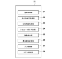
- FIG. 2 is a block diagram illustrating an example of a hardware configuration of a game device, a relay device, and an intermediary device in FIG. 1.
- FIG. 2 is a diagram schematically illustrating an example of the robot system in FIG. 1.
- FIG. 2 is a block diagram illustrating a functional configuration of a control unit of the game device in FIG. 1.
- FIG. 2 is a block diagram illustrating a functional configuration of a control unit of the relay device of FIG. 1.
- FIG. 4 is a diagram showing a processing flow before starting work of a robot in each of the game device and the relay device. It is a figure showing the processing flow after the start of work of the robot in each of the game device and the relay device. It is a figure for explaining an example of processing performed as time passes in each of a game device and a relay device.
- FIG. 1 is a block diagram showing the overall configuration of the remote operation system 1.
- the remote operation system 1 of the present embodiment includes a well-known various game device 2 (operation terminal) and a remote work site (work space; hereinafter, also referred to as an “actual work space”) different from the place where the operator is located. Is connected via the communication network 4 to the robot 51 installed in the robot. Then, the operator remotely controls the robot 51 using the game device 2 to cause the robot 51 to perform a predetermined operation.
- the remote control system 1 includes a plurality of game apparatuses 2, one intermediary apparatus 6, and a plurality of robot systems 5, which can communicate with each other via a communication network 4 such as the Internet.
- the game device 2 is, for example, a stationary game device placed at the home of the operator or a portable game device carried by the operator.
- the robot system 5 includes a robot 51 to be remotely controlled by an operator, one or more peripheral devices 52 installed around the robot 51, and a relay device 53.
- the robot 51, the peripheral device 52, and the relay device 53 are all installed at a remote work site remote from a place where an operator operating the game apparatus 2 is located. At the work site, one or more robot systems 5 exist.
- the plurality of robot systems 5 included in the remote control system 1 may be installed at the same work site or at different work sites. Also, a plurality of robot systems 5 installed at the same work site may have peripheral devices 52 shared by each other. Note that the plurality of robot systems 5 may include a plurality of peripheral devices 52 of the same type or different types. However, in FIG. 1, for simplification of the drawing, a block indicating the peripheral devices 52 is one for each robot system 5. Only one is shown.
- the relay device 53 is communicably connected to each of the robot 51 and the peripheral device 52 of the same robot system 5 including the relay device 53.
- the relay device 53 sends information transmitted from the game device 2 or the mediation device 6 to the robot 51 or the peripheral device 52 via the communication network 4 or transmits information of the robot 51 or the peripheral device 52 to the game device 2 or the mediation device 6. Or send it to
- the mediation device 6 assigns one robot system 5 to one operator (one game device 2). More specifically, the operator accesses the intermediary device 6 from the game device 2 and registers the user in advance, and the user ID is given to the operator by the user registration. When the operator inputs his / her user ID in the game device 2 and sends an operation request to the mediation device 6, the mediation device 6 that has received the operation request associates the game device 2 with one of the robot systems 5, The game device 2 is connected to the relay device 53 of the robot system 5 associated with the game device 2 via the communication network 4.
- the intermediary device 6 upon receiving an operation request from the game device 2, the intermediary device 6 sends to the game device 2 work list information indicating the content of the work or the like.
- the operation request includes desired condition information input by the operator.
- the desired condition information includes the type of the robot, the work content of the robot, the target work, the work amount, and part or all of the work time.
- the intermediary device 6 filters, based on the desired condition information included in the operation request, those that meet the conditions desired by the operator, and sends the filtered work list to the game device 2.
- designation information corresponding to the designation of the operator is transmitted from the game device 2 to the intermediary device 6. .
- the mediation device 6 connects the game device 2 to the relay device 53 of the robot system 5 corresponding to the designated information.
- the operator can remotely control the robots 51 at various work sites physically far apart using the game apparatus 2.
- the remote control system 1 allows the operator to operate the robot 51 at the work site on the back side of the earth while staying at home.
- a communication environment of each of the game device 2 and the robot system 5 and a physical distance between the game device 2 and the robot system 5 are set.
- a communication delay due to the above may occur.
- the remote operation system 1 that suppresses the influence of a communication delay occurring between the game device 2 and the robot 51 connected to each other on the operation of the operator is realized.
- FIG. 2 illustrates an example of a hardware configuration of the game device 2, the relay device 53, and the mediation device 6.
- the game device 2 includes a game device body 2a, a display device 25 (display), a speaker 27, and a controller 28 (operator) connected thereto.
- the game apparatus main body 2a includes a control unit 21, a communication unit 22, and a storage unit 23 such as a hard disk or a memory card on a bus 20.
- the control unit 21 generates operation information to be sent to the robot 51 via the communication network 4 based on the operation of the controller 28.
- the robot 51 operates based on this operation information.
- the control unit 21 generates an image displayed on the display device 25 based on an operation of the controller 28.
- the control unit 21 includes a CPU 210, a ROM (flash memory) 211, a RAM 212, an image processor 213, an audio processor 214, and an operation unit 215.
- the CPU 210 controls the operation of each unit of the game device 2.
- the ROM 211 stores a basic program of the game apparatus 2 and the like.
- the storage unit 23 stores a remote operation program for operating the robot 51 by remote operation, a game program for executing various games, and the like.
- the RAM 212 a work area used when the CPU 210 executes the game program is set.
- the storage of the remote control program in the storage unit 23 is essential, but the storage of the game program is not essential.
- the ROM 211, the RAM 212, the storage unit 23, and the like of the control unit 21 in which various programs and data are stored are collectively referred to as a storage device of the game device 2.
- the image processor 213 includes a GPU (Graphics Processing Unit) capable of generating a game screen.
- a video RAM (VRAM) 24 is connected to the image processor 213.
- a display device 25 is connected to the VRAM 24.
- the audio processor 214 includes a DSP (Digital Signal Processor) that generates game audio.
- the sound processor 214 transmits the generated game sound to the amplifier 26 including the D / A converter.
- the amplifier 26 amplifies this audio signal and transmits it to the speaker 27.
- the controller 28 is connected to the operation unit 215 by wireless or wired communication.
- the controller 28 includes a cross button, a push switch, a joystick, a mouse, a keyboard, a touch panel, and the like. Further, the operation unit 215 detects an operation signal from the user via the controller 28, and transmits the operation signal to the CPU 210.
- the communication unit 22 is a communication device that communicates with the mediation device 6 and the relay device 53 via the communication network 4.
- the mediation device 6 includes a control unit 61, a communication unit 62, and a storage unit 63.
- the control unit 61 is configured by, for example, an arithmetic unit having a processor and a memory. Specifically, the arithmetic unit is configured by, for example, a microcontroller, an MPU, an FPGA (Field Programmable Gate Array), a PLC (Programmable Logic Controller), a computer, a personal computer, and the like.
- the control unit 61 may be configured by a single arithmetic unit that performs centralized control, or may be configured by a plurality of arithmetic units that perform distributed control.
- the communication unit 62 is a communication device that communicates with the game device 2 and the relay device 53 via the communication network 4.
- the storage unit 63 is a readable / writable or readable storage device, and is, for example, a hard disk, a flash memory, an optical disk, or the like.
- the control unit 61 controls the operation of each unit of the mediation device 6.
- Various programs and data for controlling the operation of the mediation device 6, such as a program for associating the game device 2 with the robot system 5, are stored in the memory and the storage unit 63 of the control unit 61.
- the relay device 53 includes a control unit 55, a communication unit 56, and a storage unit 57.
- the control unit 55 is configured by, for example, an arithmetic unit having a processor and a memory. Specifically, the arithmetic unit is configured by, for example, a microcontroller, an MPU, an FPGA (Field Programmable Gate Array), a PLC (Programmable Logic Controller), a computer, a personal computer, and the like.
- the control unit 55 may be configured by a single arithmetic unit that performs centralized control, or may be configured by a plurality of arithmetic units that perform distributed control.
- the communication unit 56 is a communication device that communicates with the game device 2, the mediation device 6, the robot 51, and the peripheral device 52 via the communication network 4.
- the storage unit 57 is a readable / writable or readable storage device, and is, for example, a hard disk, a flash memory, an optical disk, or the like.
- the control unit 55 controls the operation of the relay device 53. Various programs and data for controlling the operation of the relay device 53 are stored in the memory and the storage unit 57 of the control unit 55.
- FIG. 3 schematically shows an example of the robot system 5.
- the robot 51 performs an operation of picking the work W conveyed by the conveyor 52a.
- the robot 51 is an industrial robot.
- the robot 51 includes a robot main body 51a to be remotely operated by an operator, and a robot controller 51b for controlling the operation of the robot main body 51a.
- the robot main body 51a shown in FIG. 3 is a vertical articulated robot arm having a tool attached to the distal end.
- a workpiece W is attached to the distal end of the vertical articulated robot arm as a tool.
- a gripping hand capable of gripping is mounted.
- the robot controller 51b includes a processor.
- the processor performs decoding, arithmetic processing, and the like of stored programs and various signals input from the outside, and controls the operation of the robot body 51a and outputs signals from various output ports. Take control.
- the robot system 5 of FIG. 3 includes, as the peripheral devices 52, a conveyor 52a for transporting a work to be worked, one or more (two in this example) imaging devices 52b for shooting the work situation of the robot 51, and a work.
- a sensor 52c for detecting the position of W is provided.
- the configuration of the robot system 5 shown in FIG. 3 is an example, and the types of the robot 51 and the peripheral devices 52 are configured according to the work of the robot 51.
- the operation of the robot 51 may be, for example, a painting operation, a lunch box arrangement operation, a welding operation, or the like, in addition to the picking operation.
- the robot 51 need not be a vertical articulated robot, but may be an industrial robot such as a horizontal articulated robot, a parallel link robot, a polar coordinate robot, a cylindrical coordinate robot, or a rectangular coordinate robot.
- the transfer device as the peripheral device 52 for transferring the work W to be worked may be a transfer device other than the conveyor.
- the peripheral device 52 may include a moving device that moves the robot body 51a.
- the one or more sensors as the peripheral device 52 may be, for example, a sensor that detects the position or posture of the robot 51 instead of or in addition to the sensor that detects the position of the work W.
- the one or more sensors as the peripheral device 52 include a sensor that detects the position, orientation, or orientation of the inspection target.
- the robot system 5 may include a plurality of imaging devices 52b as the peripheral devices 52. As shown in FIG. 3, the imaging device 52b may be attached to the robot main body 51a, or may be provided at a fixed position in the work space.
- FIG. 4 is a block diagram showing a functional configuration of the control unit 21 of the game device 2.
- the control unit 21 of the game device 2 includes, as functional components, a communication control unit 31, an operation-side time management unit 32, a state information acquisition unit 33, a simulation unit (prediction unit) 34, an image display unit 35, a communication delay measurement unit. 36, a deviation detecting unit 37, and a model correcting unit 38.
- These functional units are functionally realized in cooperation with a predetermined program stored in the storage device of the game device 2.
- the predetermined program stored in the storage device of the game device 2 includes the “data generation program” of the present invention.
- the communication control unit 31 controls the communication unit 22 to send the above-described operation request and designation information to the mediation device 6, and receive list information from the mediation device 6.
- the communication control unit 31 controls the communication unit 22 to receive information from the mediation device 6 for the mediation device 6 to make a communication connection with the robot system 5 associated with the game device 2.
- the communication control unit 31 controls the communication unit 22 to send operation information generated by the operator operating the controller 28 to the corresponding relay device 53 of the robot system 5.
- the operation-side time management unit 32 manages the time on the game device 2 side so that the time from when the operator operates the controller 28 to when the robot 51 operates based on the operation is kept constant. I do.
- the state information acquisition unit 33 and the simulation unit 34 generate at least a part of data used for generating an image displayed on the display device 25.
- the display device 25 displays, as a moving image, a work space model obtained by modeling a work space (hereinafter, “actual work space”) in which a robot (hereinafter, “actual robot”) 51 actually exists.
- the work space model includes a robot model and a peripheral object model arranged in a virtual work space.
- the robot model is a model of the real robot 51.
- the peripheral object model is a model of a predetermined peripheral object around the real robot 51 (hereinafter, “real peripheral object”).
- the actual peripheral object includes a peripheral device 52 and a work W located around the robot 51, and the peripheral object model includes a corresponding peripheral device model and a work model.
- robot model data and peripheral object model data are used for generating an image displayed on the display device 25.
- the robot model data includes static information of the real robot 51.
- the static information of the robot model includes, for example, structural information indicating the structure of the real robot 51 (the number of joints and the link length of the robot main body 51a, the structure of the tool, and the like) and information indicating the position and / or posture before starting the work. (For example, rotation angle information of a servo motor included in the robot body 51a).
- the robot model data includes dynamic information of the robot model, that is, operation information (command) of the operator on the controller 28. This operation information is used for operating the robot model, and is also transmitted from the game device 2 to the real robot 51 via the communication network 4 and used for the operation of the real robot 51.
- the real robot 51 at the work site also operates.
- the real robot 51 operates with a certain time delay from the operation of the robot model.
- the peripheral object model data includes static information of the actual peripheral object.
- the static information of the real peripheral object includes structural information of the peripheral device 52, information indicating the position and / or posture of the peripheral device 52 before the start of work, shape data and structure information of the work W to be worked by the real robot 51. , Information indicating the position and / or posture of the work W before the start of the work.
- the peripheral object model data includes information that predicts the position and orientation of the actual peripheral object a predetermined time ahead. This prediction is performed by the state information acquisition unit 33 and the simulation unit 34.
- the game device 2 including the state information acquisition unit 33 and the simulation unit 34 corresponds to the “data generation device” of the present invention.
- the state information obtaining unit 33 obtains state information indicating the state of a peripheral device 52 around the real robot 51 or the state of a real peripheral object such as a work W. Then, the simulating unit 34 simulates a change in the position or orientation of the real peripheral object over time based on the state information. For example, the state information acquisition unit 33 outputs, at a certain point, information indicating a transfer speed set in a transfer device (in this example, a conveyor 51a) as the peripheral device 52 and information indicating a position of the work W transferred to the transfer device. Is obtained as the state information, the simulation unit 34 can easily calculate the position and orientation of the work W a predetermined time ahead from the transport speed information and the work position information. As described above, the simulation unit 34 predicts the state of the real peripheral object a predetermined time later than the current time by the simulation. Then, the simulation unit 34 generates the predicted result as peripheral object model data used for creating a peripheral object model.
- a transfer speed set in a transfer device in this example, a
- the image display unit 35 displays the work space model created based on the robot model data and the peripheral object model data on the display device 25.
- the image display unit 35 arranges a virtual camera in a virtual work space in which a robot model and a peripheral object model created based on the robot model data and the peripheral object model data are arranged.
- the image captured by the virtual camera is displayed on the display device 25.
- the position, orientation, zoom, and the like of the virtual camera may be determined in advance, or may be changeable according to, for example, an operation performed on the controller 28 by an operator.
- the position and orientation of the virtual camera in the virtual work space may correspond to the position and orientation of the imaging device 52b in the real work space, respectively.
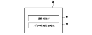
- FIG. 5 is a block diagram showing a functional configuration of the control unit 55 of the relay device 53.
- the control unit 55 of the relay device 53 has a communication control unit 71 and a robot-side time management unit 72 as a functional configuration. These functional units are functionally realized in cooperation with a predetermined program stored in the control unit 55 and / or the storage unit 57 of the relay device 53.
- the communication control unit 71 controls the communication unit 56 to receive, from the game device 2, operation information generated by the operator operating the controller 28.
- the robot-side time management unit 72 manages the time on the robot system 5 side so that the time from when the operator operates the controller 28 to when the robot 51 operates based on the operation is kept constant. I do.
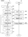
- FIG. 6 is a diagram showing a processing flow before starting work of the robot 51 in each of the game apparatus 2 and the relay apparatus 53.
- the robot model, the peripheral device model, and the work model in the work space model are created so as to be in the same state as the real robot 51, the peripheral device 52, and the work W, respectively.
- the communication control unit 71 of the relay apparatus 53 transmits information for creating a work space model before the start of work to the game apparatus. 2 (step S201).
- the information for creating the work space model before the start of the work includes state information indicating the state of the real surroundings around the real robot 51.
- the state information includes imaging information generated by imaging the peripheral device 52 and the work W by the imaging device 52b installed in the actual work space. Further, the state information includes detection information of a sensor as the peripheral device 52.
- the detection information of the sensor includes, for example, information indicating whether the work W is at a predetermined position in the work space, information indicating the position or posture of the work W, and the like.
- the state information includes setting information set in the peripheral device 52. For example, when the robot system 5 includes a transfer device as the peripheral device 52, the setting information may include a transfer speed and a transfer interval set for the transfer device.
- the transport interval may be the distance between the workpieces W to be transported, or from the time when a certain workpiece W is transported to a predetermined position in front of the robot 51, the next workpiece W is transported to a predetermined location. May be a time interval until the time.
- the status information sent from the relay device 53 to the game device 2 includes information indicating the status of the real robot 51.
- the information indicating the state of the real robot 51 may include, for example, posture information and position information of the real robot 51 stored in the robot controller 51b.
- the information indicating the state of the real robot 51 may include imaging information obtained by the imaging device 52b, which is the peripheral device 52, and detection information of the sensor 52c.
- the status information acquisition unit 33 acquires the status information received from the relay device 53 (Step S101). Then, the simulation unit 34 creates a work space model having the same state as the actual work space before the start of the work, based on the state information acquired by the state information acquisition unit 33 (step S102).
- the state information includes, for example, shape data and structure information of the work W, the position and orientation of the work W, position information and structure information of the peripheral device 52, setting information, and the like.
- the simulating unit 34 determines the position information (position coordinates in the coordinate system set for the actual work space) and the posture information (the rotation angle of the servo motor of the robot body 51a) before the start of the work. Information, etc.), a robot model is created such that the state (position, posture, etc.) of the robot model is the same as that of the real robot 51. Further, the simulating unit 34 creates a peripheral object model based on the state information of the actual peripheral object before the start of the work so that the peripheral object model is in the same state as the actual peripheral object.
- the image display unit 35 generates an image of the work space model created in step S102 and displays the image on the display device 25 (step S103). Thus, preparations for starting work are completed.
- FIG. 7 is a processing flow after the operation of the robot 51 in each of the game device 2 and the relay device 53 is started.
- FIG. 8 is a diagram for explaining an example of processing executed with time in each of game device 2 and relay device 53.
- step S105 the control unit 21 of the game device 2 determines whether or not an operation for instructing to start a work has been performed (step S105). If there is no work start instruction (Step S105: No), the state is a standby state until there is a work start instruction.
- the communication control unit 31 transmits a work start instruction to the relay device 53 (step S106). Further, the operation-side time management unit 32 stores the transmission time of the work start instruction in the storage device (the RAM 212 or the storage unit 23 or the like) of the game device 2 as the operation-side reference time t1 (step S107, see also FIG. 8). .
- the communication control unit 71 of the relay device 53 receives the work start instruction (step S202)
- the communication control unit 71 sets the work time after waiting for a predetermined time ⁇ t from the reception time of the work start instruction.
- a work start instruction is sent to the robot 51 and the peripheral device 52 (step S203).
- the robot-side time management unit 72 stores a time later than the reception time of the work start instruction by a predetermined time ⁇ t as the robot-side reference time t2 (step S204, see also FIG. 8).
- the work of the robot model is started from the operation-side reference time t1
- the real robot is started from the robot-side reference time t2.
- Work is started.
- the work start instruction sent from the game device 2 to the robot system 5 may include a command to shift the peripheral device 52 from the stopped state to the operating state.
- the work model of the work space model may start to be transported by the transfer device model from the operation-side reference time t1, and the real work W of the actual work space may be started to be transferred by the transfer device from the robot-side reference time t2.
- the robot 51 can be remotely operated. That is, when an operation for operating the robot 51 is performed on the controller 28 (step S108: Yes), operation information is generated.
- the simulation unit 34 simulates the operation of the robot model based on the operation information (Step S109). Further, the communication control unit 31 transmits to the relay device 53, together with the operation information, the elapsed time T from the reference time t1 indicating the time elapsed until the operation corresponding to the operation information is performed (step S110).
- step S205 time information indicating the time at which the operation corresponding to the operation information was performed, such as time information indicating the time at which the operation was performed, may be transmitted instead of the elapsed time T.
- the simulating unit 34 simulates the state of an actual peripheral object (step S111). Specifically, the simulation unit 34 predicts the state of the real peripheral object a predetermined time later than the current time based on the state information, and uses the predicted result as peripheral object model data used for creating a peripheral object model. Generate.
- the state information need not be the information acquired by the state information acquisition unit 33 in step S101 before the start of the work, and may be information acquired after the start of the work. That is, the latest state information may be sequentially transmitted from the robot system 5 to the game apparatus 2, and the state information acquisition unit 33 may sequentially acquire the latest state information.
- the simulating unit 34 may predict the state of a real surrounding object based on the latest state information.
- the image display unit 35 displays an image indicating the work space model on the display device 25 based on the data generated based on the simulation results in steps S109 and S111 (step S112).
- the image display unit 35 displays the work space model of the situation ahead of the actual work space situation by the difference (t2-t1) between the robot-side reference time t2 and the operation-side reference time t1.
- the actual work space is only the difference (t2-t1) between the robot-side reference time t2 and the operation-side reference time t1. Work progresses late.
- Steps S108 to S112 are repeated until an operation for terminating the operation is performed on the controller 28 or until a certain operation is completed (Step S113: No).
- the robot-side time management unit 72 does not set the reception time of the work start instruction to the robot-side reference time t2, but sets the time after waiting for a predetermined time ⁇ t from the reception time of the work start instruction to the robot-side reference time. It is set as t2.
- the robot-side time management unit 72 does not set the reception time of the work start instruction to the robot-side reference time t2, but sets the time after waiting for a predetermined time ⁇ t from the reception time of the work start instruction to the robot-side reference time. It is set as t2.
- the waiting time ⁇ t may be set based on an actual communication delay between the game apparatus 2 and the robot system 5 (specifically, the relay apparatus 53).
- the communication delay measuring unit 36 measures a communication delay between the game device 2 and the robot system 5 (more specifically, the relay device 53) associated therewith. The measurement of the communication delay is performed by a known method.
- the robot-side time management unit 72 determines the length of the waiting time ⁇ t, in other words, the robot-side reference time t2 and the operation-side reference time according to the degree of change in the communication delay measured by the communication delay measurement unit 36 before step S105. A difference (t2 ⁇ t1) from t1 may be set.
- the work space model is periodically corrected.
- the deviation detecting unit 37 detects the degree of deviation between the state of the work space model displayed on the display device 25 at a predetermined time and the state of the actual work space after a predetermined time from the predetermined time. . More specifically, the shift detecting unit 37 determines the state of the work space model at a predetermined time and the actual time after the difference (t2-t1) between the robot-side reference time t2 and the operation-side reference time t1 from the predetermined time. The degree of deviation from the state of the work space is detected.
- the shift detecting unit 37 may calculate the state of the work space model at the time ta predicted by the simulation unit 34 based on the state information indicating the state of the actual work space at a certain time ta and the state information acquired before the time ta. May be compared with each other to detect the degree of deviation.
- the state information indicating the state of the actual work space compared by the shift detection unit 37 may include the state information used by the simulation unit 34 to predict the state of the actual surroundings.
- the displacement detection unit 37 receives, for example, imaging information of the actual working space at the time ta from the robot system 5 and determines the position and orientation of the real peripheral object (the peripheral device 52 or the work W) from the imaging information by image recognition. Is also good.
- the shift detection unit 37 determines the position and orientation of the real peripheral object determined from the imaging information at time ta and the work space at time (that is, time (ta ⁇ (t2 ⁇ t1))) corresponding to the real work space at time ta. Compare the position and orientation of the peripheral object model in the model. In other words, the shift detecting unit 37 determines the state of the actual peripheral object (the position and orientation of the peripheral device 52 and the work W, etc.) determined from the imaging information at the time ta and the peripheral object just before the time ta by the time (t2-t1). Compare with model state.
- the model correcting unit 38 corrects the work space model so that the displacement is eliminated.
- the model correction unit 38 may adjust the state information used by the simulation unit 34 by the deviation detected by the deviation detection unit 37.
- the model correction unit 38 may adjust the peripheral object model data generated by the simulation unit 34 by the deviation detected by the deviation detection unit 37.
- the simulation unit 34 simulates the state of the real peripheral object after the model correction unit 38 corrects the work space model
- the simulation unit 34 simulates the state of the real peripheral object in consideration of the correction of the work space model.
- the state of the real surroundings is predicted by the simulation unit 34 a predetermined time after the current time.
- the prediction result is generated as peripheral object model data used for creating a peripheral object model displayed on the display device 25. Therefore, the same time lag between the state of the peripheral object model and the state of the real peripheral object as that between the robot model and the real robot can be generated. Thereby, the time axis of the robot model and the time axis of the peripheral object model can be made to coincide with each other, so that the influence of the communication delay on the operation of the operator can be suppressed.
- the shift detecting unit 37 detects a shift between the state of the work space model displayed on the display device 25 at a predetermined time and the state of the actual work space after a predetermined time from the predetermined time. Is detected, and the model correction unit 38 corrects the work space model such that the deviation is eliminated when the deviation detected by the deviation detecting unit 37 exceeds a preset range. Therefore, it is possible to suppress a deviation between the state of the work space model displayed on the display device 25 and the state of the actual work space.
- the game device 2 is exemplified as the operation terminal, but the operation terminal in the present invention may not be the game device 2.
- the operation terminal only needs to have an operation device that receives an operation of the operator and a display device that can be visually recognized by the operator.
- the game device 2 may be any of a personal information terminal (PDA (Personal Data Assistant)), a smartphone, a personal computer, a tablet, and a remote controller dedicated to a robot, in addition to various known game devices.
- PDA Personal Information terminal
- the control unit of the mediation device 6 or another server device may function as a state information acquisition unit and a prediction unit by executing a predetermined program.
- the “data generation device” of the present invention may not be an operation terminal operated by the operator, and may be a device that communicates with the operation terminal.
- the data generation device of the present invention may be the robot controller 51b, the relay device 53, the mediation device 6, or a server device different from the mediation device 6.
- the data generation device of the present invention may not include a part or all of the communication delay measurement unit 36, the shift detection unit 37, and the model correction unit 38.
- the “data generation program” of the present invention includes, instead of or in addition to the storage device of the game device 2 as the operation terminal, the robot controller 51b, the relay device 53, the mediation device 6, and a server separate from the mediation device 6.
- the information may be stored in a storage device provided in at least one of the devices.
- the “data generation program” of the present invention is executed by a computer incorporated in each of at least one of the robot controller 51b, the relay device 53, the mediation device 6, and a server device different from the mediation device 6, and What is necessary is just what makes a computer function as a state information acquisition unit and a prediction unit.
- the processing flows of the game device 2 and the relay device 53 described with reference to FIGS. 6 and 7 do not limit the present invention.
- the remote control system 1 may include only one game device 2. Further, the remote control system 1 may include only one robot system 5. Further, the remote control system 1 does not need to include the mediation device 6. Further, the relay device 53 and the robot controller 51b in the robot system 5 may be integrally configured. That is, the robot system 5 may include one control device having both functions of the relay device 53 and the robot controller 51b.
- the real robot in the present invention may not be an industrial robot, but may be any robot that operates according to the operation of the operator at the operation terminal.
- the real robot of the present invention may be a service robot that provides services such as care, medical care, transportation, cleaning, and cooking.
- the real robot of the present invention may be a humanoid.
- the real robot operates based on operation information generated by the operation of the operating device by the operator, but the real robot may operate based on not only the operation information but also a preset task program.
- the data generation program predicts the state of the real peripheral object after the current time based on the state information obtaining step of obtaining state information indicating the state of the real peripheral object and the state information. And a predicting step of generating the result obtained as the peripheral object model data used for creating the peripheral object model displayed on the display device, by the controller 21 of the game apparatus 2 as an operation terminal.
- the data generation program of the present invention may cause another computer to execute the above-described state information acquisition step and prediction step.
- the data generation program according to the present invention includes a controller provided in at least one of the robot controller 51b, the relay device 53, the mediation device 6, and a server device different from the mediation device 6 for performing the state information acquisition step and the prediction step described above. (A computer).
- the data generation program may be distributed and stored in a plurality of storage devices. For example, a part of the data generation program may be stored in the storage device of the operation terminal, and the other part may be stored in another storage device (for example, the relay device 53). Further, the data generation program according to the present invention may be configured such that the state of the work space model displayed on the display at a predetermined time and the state of the real work space after the predetermined time by the predetermined time are provided. May be executed by a computer. Further, the data generation program according to the present invention further includes a model correction step of correcting the work space model such that the shift is eliminated when the shift detected in the shift detection step exceeds a preset range. The program may be executed by a computer.
- Robot system 2 Game device (operation terminal) 4: Communication network 5: Robot system 6: Mediation device 25: Display device (display device) 28: Controller (operator) 33: state information acquisition unit 34: simulation unit (prediction unit) 35: Image display unit 36: Communication delay measurement unit 37: Displacement detection unit 38: Model correction unit 51: Robot 51a: Robot body 51b: Robot controller 52: Peripheral device 52a: Conveyor 52b: Imaging device 52c: Sensor 53: Relay device 55: Control unit
Abstract
This data generating device is a data generating device for generating at least some data used to generate an image to be displayed on a display unit, wherein: a working space model which models an actual working space is displayed on the display unit as a moving image; the working space model includes a robot model which models an actual robot, and a peripheral object model which models prescribed peripheral objects at the periphery of the actual robot; the robot model is created in such a way as to act in accordance with operations performed by an operator with respect to an operating device; and the data generating device is provided with a state information acquiring unit which acquires state information indicating the state of the peripheral objects, and a predicting unit which predicts the state of the peripheral objects a prescribed length of time after the current time, on the basis of the state information, and generates the predicted results as peripheral object model data to be used to generate the peripheral object model to be displayed on the display unit.
Description
本発明は、操作者がネットワークを通じて遠隔地のロボットを遠隔操作するシステムにおけるデータ生成装置、データ生成方法、データ生成プログラムおよび遠隔操作システムに関する。
The present invention relates to a data generation device, a data generation method, a data generation program, and a remote operation system in a system in which an operator remotely controls a remote robot through a network.
従来、操作者がネットワークを通じて遠隔地のロボットを遠隔操作するシステムが知られている。この種のシステムでは、操作者が操作する操作装置とロボットとの間で通信遅延が生じる虞がある。例えば特許文献1には、スレーブ装置とマスタ装置との間の通信遅延を把握することができる遠隔操作システムが開示されている。
Conventionally, there is known a system in which an operator remotely controls a robot at a remote place through a network. In this type of system, there is a possibility that a communication delay may occur between the robot and the operating device operated by the operator. For example, Patent Literature 1 discloses a remote operation system that can grasp a communication delay between a slave device and a master device.
特許文献1に開示された遠隔操作システムでは、マスタ装置とスレーブ装置とを備えている。スレーブ装置は、マスタ装置から送られた操作者の操作に対応する操作情報に従って動作するスレーブロボットを備える。スレーブロボットは、自身の作業環境を撮像する撮像機器を有しており、スレーブ装置は、作業環境を逐次撮影し、撮影した実画像をマスタ装置に送信する。マスタ装置は、スレーブロボットに送られる操作情報に基づいて動作シミュレーションを行うシミュレータを備えており、スレーブ装置から送られた実画像と動作シミュレーションにより得られたシミュレーション画像とを合成することにより表示画像を生成する。表示画像における実画像とシミュレーション画像の合成の割合は、マスタ装置とスレーブ装置の間の通信遅延に応じて変えている。具体的には、通信遅延が大きい場合は、シミュレーション画像の割合を大きくして表示画像が生成される。実画像が、スレーブロボットの状況と共に作業環境の背景等についても映りこんだ画像であるのに対して、シミュレーション画像は、スレーブロボットの状況のみを表示した画像である。このため、操作者が、表示画像における例えば作業環境の背景が色濃く映っているか等から通信遅延がどの程度生じているかを容易に把握することを可能にしている。
遠隔 The remote control system disclosed in Patent Document 1 includes a master device and a slave device. The slave device includes a slave robot that operates according to operation information corresponding to an operator's operation sent from the master device. The slave robot has an imaging device that images its own work environment, and the slave device sequentially shoots the work environment and transmits the photographed real image to the master device. The master device includes a simulator that performs an operation simulation based on operation information sent to the slave robot, and combines a real image sent from the slave device with a simulation image obtained by the operation simulation to display a display image. Generate. The ratio of the synthesis of the real image and the simulation image in the display image is changed according to the communication delay between the master device and the slave device. Specifically, when the communication delay is large, the ratio of the simulation image is increased to generate the display image. The actual image is an image that reflects the background of the work environment as well as the status of the slave robot, whereas the simulation image is an image that displays only the status of the slave robot. For this reason, it is possible for the operator to easily grasp the degree of the communication delay from the display image, for example, whether the background of the work environment appears dark.
しかしながら、特許文献1のシステムでは、操作者は、実画像とシミュレーション画像の合成割合から通信遅延の程度を判断する必要があり、また、通信遅延が大きいと判断した場合には、マスタ装置へ与える操作量を減らすなどの対応を適宜とる必要がある。このため、上述のシステムでは、操作者は、ロボットの操作以外に通信遅延に伴う状況判断を行う必要があり、操作者がロボットの操作に集中できない虞がある。
However, in the system of Patent Document 1, it is necessary for the operator to determine the degree of the communication delay from the combination ratio of the real image and the simulation image, and when it is determined that the communication delay is large, the communication delay is given to the master device. It is necessary to take appropriate measures such as reducing the amount of operation. For this reason, in the above-described system, the operator needs to make a situation determination due to the communication delay in addition to the operation of the robot, and the operator may not be able to concentrate on the operation of the robot.
そこで本発明は、操作者が操作する操作端末とロボットとの間の通信遅延が操作者の操作に与える影響を抑制することができるデータ生成装置、データ生成方法、データ生成プログラムおよび遠隔操作システムを提供することを目的とする。
Accordingly, the present invention provides a data generation device, a data generation method, a data generation program, and a remote operation system that can suppress the influence of a communication delay between an operation terminal operated by an operator and a robot on the operation of the operator. The purpose is to provide.
上記の課題を解決するために、本発明の一態様に係るデータ生成装置は、操作者の操作を受け付ける操作器および前記操作者が視認可能な表示器を有する操作端末と、実作業空間内に設置され、前記操作端末とデータ通信可能なネットワークを介して接続された実ロボットと、を備える遠隔操作システムにおいて、前記表示器に表示される画像の生成に使用される少なくとも一部のデータを生成するためのデータ生成装置であって、前記表示器には、前記実作業空間をモデル化した作業空間モデルが動画像(time-varying image)として表示され、前記作業空間モデルは、前記実ロボットをモデル化したロボットモデルと、前記実ロボットの周辺にある実周辺物をモデル化した周辺物モデルとを含み、前記ロボットモデルは、前記操作器に対する前記操作者の操作に応じて動作するように作成され、前記データ生成装置は、前記実周辺物の状態を示す状態情報を取得する状態情報取得部と、前記状態情報に基づき、現時点より所定時間分だけ後の前記実周辺物の状態を予測するとともに、予測した結果を、前記表示器に表示される前記周辺物モデルの作成に使用される周辺物モデルデータとして生成する予測部と、を備える。
In order to solve the above problems, a data generation device according to one embodiment of the present invention includes an operation terminal having an operation device that receives an operation of an operator and a display device that can be visually recognized by the operator; A remote operation system including a real robot installed and connected via a network capable of data communication with the operation terminal, wherein at least a part of data used for generation of an image displayed on the display is generated. A working space model obtained by modeling the real working space as a moving image (time-varying image) on the display, and the working space model displays the real robot. A robot model, and a peripheral object model that models an actual peripheral object around the real robot, wherein the robot model is The data generation device is created to operate in response to the operation of the operator, the data generating device acquires a state information acquisition unit that acquires state information indicating the state of the real surroundings, and a predetermined time from the current time based on the state information A prediction unit that predicts a state of the real peripheral object after a minute, and generates a predicted result as peripheral object model data used for creating the peripheral object model displayed on the display device. .
操作端末と実ロボットとの間に通信遅延がある場合、操作者が操作器を操作してからその操作に対応する動作を実ロボットが行うまでの間のタイムラグにより、同時刻におけるロボットモデルの動作と実ロボットの動作との間にずれが生じ得る。前記構成によれば、予測部により、現時点より所定時間分後の実周辺物の状態が予測され、その予測結果が表示器に表示される周辺物モデルの作成に使用される周辺物モデルデータとして生成される。このため、周辺物モデルの状態と実周辺物の状態との間にも、ロボットモデルと実ロボットとの間と同じ時間ずれを生じさせることができる。これにより、ロボットモデルと周辺物モデルとの時間軸を一致させることができるため、通信遅延が操作者の操作に与える影響を抑制することができる。
If there is a communication delay between the operating terminal and the real robot, the robot model operates at the same time due to the time lag between when the operator operates the operating device and when the real robot performs the operation corresponding to the operation. And the operation of the real robot may be shifted. According to the configuration, the prediction unit predicts the state of the real peripheral object a predetermined time later than the current time, and the prediction result is used as peripheral object model data used for creating a peripheral object model displayed on the display. Generated. Therefore, the same time lag between the state of the peripheral object model and the state of the real peripheral object as that between the robot model and the real robot can be generated. Thereby, the time axis of the robot model and the time axis of the peripheral object model can be made to coincide with each other, so that the influence of the communication delay on the operation of the operator can be suppressed.
前記実周辺物は、前記実ロボットの作業対象であるワーク、前記ワークを搬送する搬送装置、および前記実ロボットを移動させる移動装置の少なくとも1つを含んでもよい。
The real peripheral object may include at least one of a work to be worked by the real robot, a transfer device for transferring the work, and a moving device for moving the real robot.
前記状態情報は、前記作業空間に設置された撮像装置が前記実周辺物を撮像することにより生成される撮像情報を含んでもよい。
The state information may include imaging information generated by an imaging device installed in the work space imaging the real surroundings.
前記状態情報は、前記実周辺物としての周辺機器に設定された設定情報を含んでもよい。
状態 The state information may include setting information set in a peripheral device as the real peripheral object.
上記のデータ生成装置は、所定の時点において前記表示器に表示された前記作業空間モデルの状況と、前記所定の時点より前記所定時間分だけ後の前記実作業空間の状況との間のズレの程度を検知するズレ検知部を更に備えてもよい。例えば、ズレ検知部により検知されるズレが所定の値より大きい場合に、実ロボットの作業を停止させる、あるいは表示器に表示されるモデルを補正するなどの対応が可能になる。
The data generation device described above, the deviation of the state between the state of the work space model displayed on the display at a predetermined time and the state of the real work space after the predetermined time by the predetermined time A deviation detecting unit for detecting the degree may be further provided. For example, when the displacement detected by the displacement detection unit is larger than a predetermined value, it is possible to take measures such as stopping the operation of the actual robot or correcting the model displayed on the display.
上記のデータ生成装置は、前記ズレ検知部により検知されたズレが予め設定された範囲を超えた場合に、前記ズレが解消されるように前記作業空間モデルを補正するモデル補正部を更に備えてもよい。
The data generation device further includes a model correction unit that corrects the work space model so that the deviation is eliminated when the deviation detected by the deviation detecting unit exceeds a preset range. Is also good.
前記操作端末は、前記操作器としてのコントローラを含むゲーム装置であってもよい。
The operation terminal may be a game device including a controller as the operation device.
前記操作端末は、個人情報端末(PDA(Personal Data Assistant))、スマートフォン、パーソナルコンピュータ、タブレット、およびロボット専用遠隔操作器のうちの少なくとも1つであってもよい。
The operation terminal may be at least one of a personal information terminal (PDA (Personal Data Assistant)), a smartphone, a personal computer, a tablet, and a remote controller dedicated to a robot.
また、本発明の一態様に係るデータ生成方法は、操作者の操作を受け付ける操作器および前記操作者が視認可能な表示器を有する操作端末と、作業空間内に設置され、前記操作端末とデータ通信可能なネットワークを介して接続された実ロボットと、を備える遠隔操作システムにおいて、前記表示器に表示される画像の生成に使用される少なくとも一部のデータを生成するためのデータ生成方法であって、前記表示器には、前記実作業空間をモデル化した作業空間モデルが動画像として表示され、前記作業空間モデルは、前記実ロボットをモデル化したロボットモデルと、前記実ロボットの周辺にある周辺物をモデル化した周辺物モデルとを含み、前記ロボットモデルは、前記操作器に対する前記操作者の操作に応じて動作するように作成され、前記データ生成方法は、前記実ロボットの周辺にある周辺物の状態を示す状態情報を取得する状態情報取得ステップと、前記状態情報に基づき、現時点より後の前記周辺物の状態を予測するとともに、予測した結果を、前記表示器に表示される前記周辺物モデルの作成に使用される周辺物モデルデータとして生成する予測ステップと、を含む。
In addition, a data generation method according to one embodiment of the present invention includes an operation device having an operation device that accepts an operation of an operator and a display device that can be visually recognized by the operator; and an operation terminal installed in a work space; In a remote operation system including a real robot connected via a communicable network, a data generating method for generating at least a part of data used for generating an image displayed on the display. A work space model that models the real work space is displayed as a moving image on the display, and the work space model is located around the real robot and a robot model that models the real robot. A peripheral object model obtained by modeling a peripheral object, wherein the robot model is created so as to operate in accordance with the operation of the operator on the operation device. Wherein the data generation method includes: a state information obtaining step of obtaining state information indicating a state of a peripheral object around the real robot; and predicting a state of the peripheral object after the present time based on the state information. A prediction step of generating a predicted result as peripheral object model data used for creating the peripheral object model displayed on the display.
また、本発明の一態様に係るデータ生成プログラムは、操作者の操作を受け付ける操作器および前記操作者が視認可能な表示器を有する操作端末と、作業空間内に設置され、前記操作端末とデータ通信可能なネットワークを介して接続された実ロボットと、を備える遠隔操作システムにおいて、コンピュータに実行されることにより、前記表示器に表示される画像の生成に使用される少なくとも一部のデータを生成するデータ生成プログラムであって、前記表示器には、前記実作業空間をモデル化した作業空間モデルが動画像として表示され、前記作業空間モデルは、前記実ロボットをモデル化したロボットモデルと、前記実ロボットの周辺にある周辺物をモデル化した周辺物モデルとを含み、前記ロボットモデルは、前記操作器に対する前記操作者の操作により生成され、前記データ生成プログラムは、前記実ロボットの周辺にある周辺物の状態を示す状態情報を取得する状態情報取得ステップと、前記状態情報に基づき、現時点より後の前記周辺物の状態を予測するとともに、予測した結果を、前記表示器に表示される前記周辺物モデルの作成に使用される周辺物モデルデータとして生成する予測ステップと、を前記コンピュータに実行させる。
In addition, a data generation program according to one embodiment of the present invention includes an operation device having an operation device that receives an operation of an operator and a display device that can be visually recognized by the operator; And a real robot connected via a communicable network, wherein at least a part of data used for generating an image displayed on the display is generated by being executed by a computer. A data generation program, wherein the display device displays, as a moving image, a work space model that models the real work space, wherein the work space model includes a robot model that models the real robot, A peripheral object model that models a peripheral object around the real robot, wherein the robot model is The data generation program is generated by an operation of the operator, and the data generation program obtains state information indicating a state of a peripheral object around the real robot, and based on the state information, A prediction step of predicting a state of the peripheral object and generating a result of the prediction as peripheral object model data used for creating the peripheral object model displayed on the display device.
なお、前記データ生成プログラムは、記憶装置に記憶される。前記記憶装置は、コンピュータに内蔵または外付けされる読み書き可能または読み取り可能な装置であり、例えば、ハードディスク、フラッシュメモリ、光ディスク等を用いることができる。前記記憶装置に記憶されたプログラムは、前記記憶装置が直接接続されるコンピュータにおいて実行されてもよいし、前記記憶装置とネットワーク(例えば、インターネット)を介して接続されたコンピュータにおいてダウンロードされて実行されてもよい。
The data generation program is stored in a storage device. The storage device is a readable / writable or readable device built in or external to the computer, and may be, for example, a hard disk, a flash memory, an optical disk, or the like. The program stored in the storage device may be executed on a computer to which the storage device is directly connected, or may be downloaded and executed on a computer connected to the storage device via a network (for example, the Internet). You may.
また、本発明の一態様に係る遠隔操作システムは、操作者の操作を受け付ける操作器および前記操作者が視認可能な表示器を有する操作端末と、実作業空間内に設置され、前記操作端末とデータ通信可能なネットワークを介して接続された実ロボットと、を備える遠隔操作システムであって、前記表示器には、前記実作業空間をモデル化した作業空間モデルが動画像として表示され、前記作業空間モデルは、前記実ロボットをモデル化したロボットモデルと、前記実ロボットの周辺にある実周辺物をモデル化した周辺物モデルとを含み、前記ロボットモデルは、前記操作器に対する前記操作者の操作に応じて動作するように作成され、前記遠隔操作システムは、前記実周辺物の状態を示す状態情報を取得する状態情報取得部と、前記状態情報に基づき、現時点より所定時間分だけ後の前記実周辺物の状態を予測するとともに、予測した結果を、前記表示器に表示される前記周辺物モデルの作成に使用される周辺物モデルデータとして生成する予測部とを備えるデータ生成装置を備える。
Further, the remote operation system according to one aspect of the present invention is an operation terminal having an operation device that receives an operation of an operator and a display device that can be visually recognized by the operator, and is installed in an actual work space, and the operation terminal A real robot connected via a network capable of data communication, wherein the display device displays a working space model obtained by modeling the real working space as a moving image, The space model includes a robot model that models the real robot and a peripheral object model that models a real peripheral object around the real robot, wherein the robot model is operated by the operator with respect to the operating device. The remote operation system is configured to operate in accordance with the state information acquisition unit that acquires state information indicating the state of the real surroundings; And predicting the state of the real peripheral object a predetermined time later than the current time, and generating the predicted result as peripheral object model data used for creating the peripheral object model displayed on the display. And a data generation device including a prediction unit that performs the calculation.
本発明によれば、操作者が操作する操作端末とロボットとの間の通信遅延が操作者の操作に与える影響を抑制することができる。
According to the present invention, it is possible to suppress the influence of the communication delay between the operation terminal operated by the operator and the robot on the operation of the operator.
以下、本発明の一実施形態について、図面を参照しながら説明する。
Hereinafter, an embodiment of the present invention will be described with reference to the drawings.
(システムの概要)
まず本実施形態に係る遠隔操作システム1の概要を、図1を参照して説明する。図1は、遠隔操作システム1の全体構成を示すブロック図である。本実施形態の遠隔操作システム1は、公知の各種ゲーム装置2(操作端末)と、操作者の居る場所とは異なる遠隔地の作業現場(作業空間。以下、「実作業空間」ともいう。)に設置されたロボット51とを通信ネットワーク4を介して接続する。そして、操作者にゲーム装置2を用いてロボット51を遠隔操作させて、当該ロボット51に所定の作業を遂行させる。 (Overview of the system)
First, an outline of aremote operation system 1 according to the present embodiment will be described with reference to FIG. FIG. 1 is a block diagram showing the overall configuration of the remote operation system 1. The remote operation system 1 of the present embodiment includes a well-known various game device 2 (operation terminal) and a remote work site (work space; hereinafter, also referred to as an “actual work space”) different from the place where the operator is located. Is connected via the communication network 4 to the robot 51 installed in the robot. Then, the operator remotely controls the robot 51 using the game device 2 to cause the robot 51 to perform a predetermined operation.
まず本実施形態に係る遠隔操作システム1の概要を、図1を参照して説明する。図1は、遠隔操作システム1の全体構成を示すブロック図である。本実施形態の遠隔操作システム1は、公知の各種ゲーム装置2(操作端末)と、操作者の居る場所とは異なる遠隔地の作業現場(作業空間。以下、「実作業空間」ともいう。)に設置されたロボット51とを通信ネットワーク4を介して接続する。そして、操作者にゲーム装置2を用いてロボット51を遠隔操作させて、当該ロボット51に所定の作業を遂行させる。 (Overview of the system)
First, an outline of a
遠隔操作システム1は、複数のゲーム装置2と、1つの仲介装置6と、複数のロボットシステム5とを含み、これらは例えばインターネット等の通信ネットワーク4を介して相互に通信可能となっている。ゲーム装置2は、例えば操作者の自宅などに置かれた据え置き型のゲーム装置または操作者が携帯する携帯型ゲーム装置である。
The remote control system 1 includes a plurality of game apparatuses 2, one intermediary apparatus 6, and a plurality of robot systems 5, which can communicate with each other via a communication network 4 such as the Internet. The game device 2 is, for example, a stationary game device placed at the home of the operator or a portable game device carried by the operator.
ロボットシステム5は、操作者に遠隔操作される対象であるロボット51と、ロボット51の周辺に設置された1以上の周辺機器52と、中継装置53とを備える。ロボット51、周辺機器52および中継装置53はいずれも、ゲーム装置2を操作する操作者が居る場所から離れた遠隔地の作業現場に設置されている。作業現場には、1以上のロボットシステム5が存在する。
The robot system 5 includes a robot 51 to be remotely controlled by an operator, one or more peripheral devices 52 installed around the robot 51, and a relay device 53. The robot 51, the peripheral device 52, and the relay device 53 are all installed at a remote work site remote from a place where an operator operating the game apparatus 2 is located. At the work site, one or more robot systems 5 exist.
なお、遠隔操作システム1が有する複数のロボットシステム5の一部または全部は、互いに同じ作業現場に設置されていてもよいし異なる作業現場に設置されていてもよい。また、同じ作業現場に設置された複数のロボットシステム5が、互いに共有する周辺機器52を有していてもよい。なお、複数のロボットシステム5は、互いに種類が同じまたは異なる複数の周辺機器52を含み得るが、図1では、図の簡略化のため、周辺機器52を示すブロックを1のロボットシステム5につき1つだけ示す。
Note that some or all of the plurality of robot systems 5 included in the remote control system 1 may be installed at the same work site or at different work sites. Also, a plurality of robot systems 5 installed at the same work site may have peripheral devices 52 shared by each other. Note that the plurality of robot systems 5 may include a plurality of peripheral devices 52 of the same type or different types. However, in FIG. 1, for simplification of the drawing, a block indicating the peripheral devices 52 is one for each robot system 5. Only one is shown.
中継装置53は、当該中継装置53を含む同じロボットシステム5のロボット51および周辺機器52のそれぞれに通信可能に接続されている。中継装置53は、通信ネットワーク4を介して、ゲーム装置2または仲介装置6から送られる情報をロボット51または周辺機器52に送ったり、ロボット51または周辺機器52の情報をゲーム装置2または仲介装置6に送ったりする。
The relay device 53 is communicably connected to each of the robot 51 and the peripheral device 52 of the same robot system 5 including the relay device 53. The relay device 53 sends information transmitted from the game device 2 or the mediation device 6 to the robot 51 or the peripheral device 52 via the communication network 4 or transmits information of the robot 51 or the peripheral device 52 to the game device 2 or the mediation device 6. Or send it to
仲介装置6は、1の操作者(1のゲーム装置2)に対して1のロボットシステム5を割り当てる。より詳しくは、操作者は、ゲーム装置2から仲介装置6にアクセスして予めユーザ登録を行っており、ユーザ登録により操作者にはユーザIDが付与されている。操作者はゲーム装置2において自己のユーザIDを入力し仲介装置6に対して操作要求を送ると、操作要求を受信した仲介装置6は、ゲーム装置2をいずれかのロボットシステム5に対応付けるとともに、ゲーム装置2と対応付けたロボットシステム5の中継装置53とを、通信ネットワーク4を介して互いに通信接続させる。
The mediation device 6 assigns one robot system 5 to one operator (one game device 2). More specifically, the operator accesses the intermediary device 6 from the game device 2 and registers the user in advance, and the user ID is given to the operator by the user registration. When the operator inputs his / her user ID in the game device 2 and sends an operation request to the mediation device 6, the mediation device 6 that has received the operation request associates the game device 2 with one of the robot systems 5, The game device 2 is connected to the relay device 53 of the robot system 5 associated with the game device 2 via the communication network 4.
例えば仲介装置6は、ゲーム装置2から操作要求を受け付けると、作業内容などを示す作業リスト情報を当該ゲーム装置2に送る。操作要求には、操作者が入力した希望条件情報が含まれる。希望条件情報には、ロボットの種類、ロボットの作業内容、対象ワーク、作業量、作業時間の一部または全部が含まれる。仲介装置6は、操作要求を受信すると、その操作要求に含まれる希望条件情報に基づき、操作者が希望する条件に合うものをフィルタリングし、ゲーム装置2にフィルタリングされた作業リストを送る。操作者はゲーム装置2の表示装置25に表示された作業リストの中から、希望するものを1つ指定すると、ゲーム装置2から仲介装置6に、操作者の指定に対応した指定情報が送られる。仲介装置6は、そのゲーム装置2を、指定情報に対応するロボットシステム5の中継装置53に接続する。
For example, upon receiving an operation request from the game device 2, the intermediary device 6 sends to the game device 2 work list information indicating the content of the work or the like. The operation request includes desired condition information input by the operator. The desired condition information includes the type of the robot, the work content of the robot, the target work, the work amount, and part or all of the work time. Upon receiving the operation request, the intermediary device 6 filters, based on the desired condition information included in the operation request, those that meet the conditions desired by the operator, and sends the filtered work list to the game device 2. When the operator designates one desired item from the work list displayed on the display device 25 of the game device 2, designation information corresponding to the designation of the operator is transmitted from the game device 2 to the intermediary device 6. . The mediation device 6 connects the game device 2 to the relay device 53 of the robot system 5 corresponding to the designated information.
このように、遠隔操作システム1では、操作者がゲーム装置2を用いて物理的に遠く離れた様々な作業現場のロボット51を遠隔操作することが可能となっている。例えば、遠隔操作システム1により、操作者は自宅に居ながら、地球の裏側の作業現場にあるロボット51を操作することが可能である。互いに接続されたゲーム装置2とロボットシステム5(より詳しくはロボット51)との間には、ゲーム装置2およびロボットシステム5の各々の通信環境やゲーム装置2およびロボットシステム5の互いの物理的距離などに起因した通信遅延が生じ得る。本実施形態では、後述するように、互いに接続されたゲーム装置2とロボット51との間に生じる通信遅延が、操作者の操作に与える影響を抑制する遠隔操作システム1を実現している。
As described above, in the remote control system 1, the operator can remotely control the robots 51 at various work sites physically far apart using the game apparatus 2. For example, the remote control system 1 allows the operator to operate the robot 51 at the work site on the back side of the earth while staying at home. Between the game device 2 and the robot system 5 (more specifically, the robot 51) connected to each other, a communication environment of each of the game device 2 and the robot system 5 and a physical distance between the game device 2 and the robot system 5 are set. For example, a communication delay due to the above may occur. In the present embodiment, as will be described later, the remote operation system 1 that suppresses the influence of a communication delay occurring between the game device 2 and the robot 51 connected to each other on the operation of the operator is realized.
(ハードウェア構成)
図2に、ゲーム装置2、中継装置53および仲介装置6のハードウェア構成の一例を示す。なお、図2では、複数のゲーム装置2のうちの1のゲーム装置2のみ示し、複数のロボットシステム5のうちの1のロボットシステム5のみ示す。ゲーム装置2は、ゲーム装置本体2aと、それに接続される表示装置25(表示器)、スピーカ27、コントローラ28(操作器)を備える。 (Hardware configuration)
FIG. 2 illustrates an example of a hardware configuration of thegame device 2, the relay device 53, and the mediation device 6. In FIG. 2, only one game device 2 of the plurality of game devices 2 is shown, and only one robot system 5 of the plurality of robot systems 5 is shown. The game device 2 includes a game device body 2a, a display device 25 (display), a speaker 27, and a controller 28 (operator) connected thereto.
図2に、ゲーム装置2、中継装置53および仲介装置6のハードウェア構成の一例を示す。なお、図2では、複数のゲーム装置2のうちの1のゲーム装置2のみ示し、複数のロボットシステム5のうちの1のロボットシステム5のみ示す。ゲーム装置2は、ゲーム装置本体2aと、それに接続される表示装置25(表示器)、スピーカ27、コントローラ28(操作器)を備える。 (Hardware configuration)
FIG. 2 illustrates an example of a hardware configuration of the
図2に示すように、ゲーム装置本体2aは、バス20上に制御部21、通信部22、およびハードディスクまたはメモリーカード等の記憶部23を備える。制御部21は、コントローラ28の操作に基づき、通信ネットワーク4を介してロボット51に送られる操作情報を生成する。なお、ロボット51は、この操作情報に基づき動作する。また、制御部21は、コントローラ28の操作に基づき、表示装置25に表示される画像を生成する。このような制御部21は、CPU210、ROM(フラッシュメモリ)211、RAM212、画像プロセッサ213、音声プロセッサ214、および操作部215を備えている。
As shown in FIG. 2, the game apparatus main body 2a includes a control unit 21, a communication unit 22, and a storage unit 23 such as a hard disk or a memory card on a bus 20. The control unit 21 generates operation information to be sent to the robot 51 via the communication network 4 based on the operation of the controller 28. The robot 51 operates based on this operation information. Further, the control unit 21 generates an image displayed on the display device 25 based on an operation of the controller 28. The control unit 21 includes a CPU 210, a ROM (flash memory) 211, a RAM 212, an image processor 213, an audio processor 214, and an operation unit 215.
CPU210はゲーム装置2の各部の動作を制御する。ROM211には、ゲーム装置2の基本プログラム等が記憶されている。記憶部23には、遠隔操作によりロボット51を動作させるための遠隔操作プログラムや、各種ゲームを実行するためのゲームプログラム等が記憶されている。RAM212には、CPU210がゲームプログラムを実行する際に使用されるワークエリアが設定される。なお、本実施形態では、記憶部23における上記遠隔操作プログラムの記憶は必須であるが、上記ゲームプログラムの記憶は必須ではない。なお、以下の説明では、各種プログラムやデータが記憶された制御部21のROM211やRAM212および記憶部23などを総称して、ゲーム装置2の記憶装置と呼ぶこととする。
The CPU 210 controls the operation of each unit of the game device 2. The ROM 211 stores a basic program of the game apparatus 2 and the like. The storage unit 23 stores a remote operation program for operating the robot 51 by remote operation, a game program for executing various games, and the like. In the RAM 212, a work area used when the CPU 210 executes the game program is set. In the present embodiment, the storage of the remote control program in the storage unit 23 is essential, but the storage of the game program is not essential. In the following description, the ROM 211, the RAM 212, the storage unit 23, and the like of the control unit 21 in which various programs and data are stored are collectively referred to as a storage device of the game device 2.
画像プロセッサ213は、ゲーム画面を生成可能なGPU(Graphics Processing Unit)を備える。画像プロセッサ213には、ビデオRAM(VRAM)24が接続される。このVRAM24には表示装置25が接続されている。
The image processor 213 includes a GPU (Graphics Processing Unit) capable of generating a game screen. A video RAM (VRAM) 24 is connected to the image processor 213. A display device 25 is connected to the VRAM 24.
音声プロセッサ214は、ゲーム音声を生成するDSP(Digital Signal Processor)を備える。音声プロセッサ214は、生成したゲーム音声をD/Aコンバータを含むアンプ26に送信する。アンプ26は、この音声信号を増幅してスピーカ27に送信する。
The audio processor 214 includes a DSP (Digital Signal Processor) that generates game audio. The sound processor 214 transmits the generated game sound to the amplifier 26 including the D / A converter. The amplifier 26 amplifies this audio signal and transmits it to the speaker 27.
操作部215には、コントローラ28が無線または有線で通信接続されている。コントローラ28は、十字ボタン、プッシュスイッチ、ジョイスティック、マウス、キーボードおよびタッチパネルなどを含む。また、操作部215は、ユーザによるコントローラ28を介した操作信号を検出し、その操作信号をCPU210に送信する。
The controller 28 is connected to the operation unit 215 by wireless or wired communication. The controller 28 includes a cross button, a push switch, a joystick, a mouse, a keyboard, a touch panel, and the like. Further, the operation unit 215 detects an operation signal from the user via the controller 28, and transmits the operation signal to the CPU 210.
通信部22は、通信ネットワーク4を介して仲介装置6および中継装置53と通信する通信機器である。
The communication unit 22 is a communication device that communicates with the mediation device 6 and the relay device 53 via the communication network 4.
仲介装置6は、制御部61、通信部62および記憶部63を備えている。制御部61は、例えばプロセッサとメモリとを有する演算器で構成される。この演算器は、具体的には、例えばマイクロコントローラ、MPU、FPGA(Field Programmable Gate Array)、PLC(Programmable Logic Controller)、コンピュータ、パーソナルコンピュータなどで構成される。制御部61は、集中制御を行う単独の演算器で構成されてもよく、分散制御を行う複数の演算器で構成されてもよい。通信部62は、通信ネットワーク4を介してゲーム装置2および中継装置53と通信する通信機器である。記憶部63は、読み書き可能または読み取り可能な記憶装置であり、例えば、ハードディスク、フラッシュメモリ、光ディスク等である。制御部61は仲介装置6の各部の動作を制御する。制御部61のメモリや記憶部63には、ゲーム装置2をロボットシステム5に対応付けを行うプログラムなどの仲介装置6の動作を制御する各種プログラムやデータが記憶されている。
The mediation device 6 includes a control unit 61, a communication unit 62, and a storage unit 63. The control unit 61 is configured by, for example, an arithmetic unit having a processor and a memory. Specifically, the arithmetic unit is configured by, for example, a microcontroller, an MPU, an FPGA (Field Programmable Gate Array), a PLC (Programmable Logic Controller), a computer, a personal computer, and the like. The control unit 61 may be configured by a single arithmetic unit that performs centralized control, or may be configured by a plurality of arithmetic units that perform distributed control. The communication unit 62 is a communication device that communicates with the game device 2 and the relay device 53 via the communication network 4. The storage unit 63 is a readable / writable or readable storage device, and is, for example, a hard disk, a flash memory, an optical disk, or the like. The control unit 61 controls the operation of each unit of the mediation device 6. Various programs and data for controlling the operation of the mediation device 6, such as a program for associating the game device 2 with the robot system 5, are stored in the memory and the storage unit 63 of the control unit 61.
中継装置53は、制御部55、通信部56および記憶部57を備えている。制御部55は、例えばプロセッサとメモリとを有する演算器で構成される。この演算器は、具体的には、例えばマイクロコントローラ、MPU、FPGA(Field Programmable Gate Array)、PLC(Programmable Logic Controller)、コンピュータ、パーソナルコンピュータなどで構成される。制御部55は、集中制御を行う単独の演算器で構成されてもよく、分散制御を行う複数の演算器で構成されてもよい。通信部56は、通信ネットワーク4を介してゲーム装置2、仲介装置6、ロボット51、および周辺機器52と通信する通信機器である。記憶部57は、読み書き可能または読み取り可能な記憶装置であり、例えば、ハードディスク、フラッシュメモリ、光ディスク等である。制御部55は、中継装置53の動作を制御する。制御部55のメモリや記憶部57には、中継装置53の動作を制御する各種プログラムやデータが記憶されている。
The relay device 53 includes a control unit 55, a communication unit 56, and a storage unit 57. The control unit 55 is configured by, for example, an arithmetic unit having a processor and a memory. Specifically, the arithmetic unit is configured by, for example, a microcontroller, an MPU, an FPGA (Field Programmable Gate Array), a PLC (Programmable Logic Controller), a computer, a personal computer, and the like. The control unit 55 may be configured by a single arithmetic unit that performs centralized control, or may be configured by a plurality of arithmetic units that perform distributed control. The communication unit 56 is a communication device that communicates with the game device 2, the mediation device 6, the robot 51, and the peripheral device 52 via the communication network 4. The storage unit 57 is a readable / writable or readable storage device, and is, for example, a hard disk, a flash memory, an optical disk, or the like. The control unit 55 controls the operation of the relay device 53. Various programs and data for controlling the operation of the relay device 53 are stored in the memory and the storage unit 57 of the control unit 55.
図3に、ロボットシステム5の一例を模式的に示す。このロボットシステム5では、コンベア52aにて搬送されるワークWをピッキングする作業をロボット51が行う。図3に示されたロボットシステム5において、ロボット51は、産業用ロボットである。ロボット51は、操作者に遠隔操作される対象であるロボット本体51aと、ロボット本体51aの動作を制御するロボットコントローラ51bとを含む。図3に示したロボット本体51aは、先端部にツールが装着された垂直多関節型のロボットアームであり、本例では、ツールとして、垂直多関節型のロボットアームの先端部には、ワークWを把持可能な把持ハンドが装着されている。ロボットコントローラ51bは、プロセッサを備えており、格納されたプログラムや外部から入力される各種信号の解読・演算処理などをプロセッサで行い、ロボット本体51aの動作制御、各種出力ポートからの信号出力などをつかさどる。また、図3のロボットシステム5は、周辺機器52として、作業対象であるワークを搬送するコンベア52a、ロボット51の作業状況を撮像する1以上の(本例では2つの)撮像装置52b、およびワークWの位置を検知するセンサ52cなどを備える。
FIG. 3 schematically shows an example of the robot system 5. In the robot system 5, the robot 51 performs an operation of picking the work W conveyed by the conveyor 52a. In the robot system 5 shown in FIG. 3, the robot 51 is an industrial robot. The robot 51 includes a robot main body 51a to be remotely operated by an operator, and a robot controller 51b for controlling the operation of the robot main body 51a. The robot main body 51a shown in FIG. 3 is a vertical articulated robot arm having a tool attached to the distal end. In this example, a workpiece W is attached to the distal end of the vertical articulated robot arm as a tool. A gripping hand capable of gripping is mounted. The robot controller 51b includes a processor. The processor performs decoding, arithmetic processing, and the like of stored programs and various signals input from the outside, and controls the operation of the robot body 51a and outputs signals from various output ports. Take control. Further, the robot system 5 of FIG. 3 includes, as the peripheral devices 52, a conveyor 52a for transporting a work to be worked, one or more (two in this example) imaging devices 52b for shooting the work situation of the robot 51, and a work. A sensor 52c for detecting the position of W is provided.
なお、図3に示されたロボットシステム5の構成は、一例であり、ロボット51や周辺機器52の種類などは、ロボット51の作業内容に応じた構成となっている。例えば、ロボット51の作業は、ピッキング作業の他にも、例えば塗装作業や弁当盛り付け作業、溶接作業等であってもよい。また、ロボット51は、垂直多関節型ロボットでなくてもよく、例えば水平多関節型ロボット、パラレルリンク型ロボット、極座標ロボット、円筒座標型ロボット、直角座標型ロボット等の産業用ロボットでもよい。また、作業対象であるワークWを搬送する周辺機器52としての搬送装置は、コンベア以外の搬送装置でもよい。周辺機器52は、ロボット本体51aを移動させる移動装置を含んでもよい。周辺機器52としての1以上のセンサは、ワークWの位置を検知するセンサの代わりにまたは加えて、ロボット51の位置や姿勢を検知するセンサなどであってもよい。周辺機器52としての1以上のセンサには、検査対象物の位置、向きまたは向きを検知するセンサを含む。また、ロボットシステム5は、周辺機器52として複数の撮像装置52bを備えてもよい。図3に示すように、撮像装置52bはロボット本体51aに取り付けられていてもよいし、作業空間において固定した位置に設けられていてもよい。
The configuration of the robot system 5 shown in FIG. 3 is an example, and the types of the robot 51 and the peripheral devices 52 are configured according to the work of the robot 51. For example, the operation of the robot 51 may be, for example, a painting operation, a lunch box arrangement operation, a welding operation, or the like, in addition to the picking operation. The robot 51 need not be a vertical articulated robot, but may be an industrial robot such as a horizontal articulated robot, a parallel link robot, a polar coordinate robot, a cylindrical coordinate robot, or a rectangular coordinate robot. Further, the transfer device as the peripheral device 52 for transferring the work W to be worked may be a transfer device other than the conveyor. The peripheral device 52 may include a moving device that moves the robot body 51a. The one or more sensors as the peripheral device 52 may be, for example, a sensor that detects the position or posture of the robot 51 instead of or in addition to the sensor that detects the position of the work W. The one or more sensors as the peripheral device 52 include a sensor that detects the position, orientation, or orientation of the inspection target. Further, the robot system 5 may include a plurality of imaging devices 52b as the peripheral devices 52. As shown in FIG. 3, the imaging device 52b may be attached to the robot main body 51a, or may be provided at a fixed position in the work space.
(機能的構成)
図4は、ゲーム装置2の制御部21の機能的構成を示すブロック図である。ゲーム装置2の制御部21は、機能的構成として、通信制御部31、操作側時間管理部32、状態情報取得部33、シミュレート部(予測部)34、画像表示部35、通信遅延計測部36、ズレ検知部37、モデル補正部38を有している。これらの機能部は、ゲーム装置2の記憶装置に記憶された所定のプログラムとの協働によって機能的に実現される。なお、ゲーム装置2の記憶装置に記憶された所定のプログラムには、本発明の「データ生成プログラム」が含まれる。 (Functional configuration)
FIG. 4 is a block diagram showing a functional configuration of thecontrol unit 21 of the game device 2. The control unit 21 of the game device 2 includes, as functional components, a communication control unit 31, an operation-side time management unit 32, a state information acquisition unit 33, a simulation unit (prediction unit) 34, an image display unit 35, a communication delay measurement unit. 36, a deviation detecting unit 37, and a model correcting unit 38. These functional units are functionally realized in cooperation with a predetermined program stored in the storage device of the game device 2. The predetermined program stored in the storage device of the game device 2 includes the “data generation program” of the present invention.
図4は、ゲーム装置2の制御部21の機能的構成を示すブロック図である。ゲーム装置2の制御部21は、機能的構成として、通信制御部31、操作側時間管理部32、状態情報取得部33、シミュレート部(予測部)34、画像表示部35、通信遅延計測部36、ズレ検知部37、モデル補正部38を有している。これらの機能部は、ゲーム装置2の記憶装置に記憶された所定のプログラムとの協働によって機能的に実現される。なお、ゲーム装置2の記憶装置に記憶された所定のプログラムには、本発明の「データ生成プログラム」が含まれる。 (Functional configuration)
FIG. 4 is a block diagram showing a functional configuration of the
通信制御部31は、通信部22を制御して、仲介装置6に上述した操作要求や指定情報を送ったり、仲介装置6からリスト情報を受信したりする。また、通信制御部31は、通信部22を制御して、仲介装置6がゲーム装置2と対応付けたロボットシステム5と通信接続するための情報を仲介装置6から受信する。また、通信制御部31は、通信部22を制御して、操作者がコントローラ28を操作することで生成された操作情報を、対応するロボットシステム5の中継装置53に送る。
The communication control unit 31 controls the communication unit 22 to send the above-described operation request and designation information to the mediation device 6, and receive list information from the mediation device 6. In addition, the communication control unit 31 controls the communication unit 22 to receive information from the mediation device 6 for the mediation device 6 to make a communication connection with the robot system 5 associated with the game device 2. Further, the communication control unit 31 controls the communication unit 22 to send operation information generated by the operator operating the controller 28 to the corresponding relay device 53 of the robot system 5.
操作側時間管理部32は、コントローラ28に対して操作者が操作してから、その操作に基づきロボット51が動作するまでの時間が一定に保たれるように、ゲーム装置2側の時間を管理する。
The operation-side time management unit 32 manages the time on the game device 2 side so that the time from when the operator operates the controller 28 to when the robot 51 operates based on the operation is kept constant. I do.
状態情報取得部33およびシミュレート部34は、表示装置25に表示される画像の生成に使用される少なくとも一部のデータを生成する。具体的には、表示装置25には、ロボット(以下、「実ロボット」)51が実際に存在する作業空間(以下、「実作業空間」)をモデル化した作業空間モデルが動画像として表示される。作業空間モデルは、仮想の作業空間に配置されたロボットモデルおよび周辺物モデルを含む。ロボットモデルは、実ロボット51をモデル化したものである。周辺物モデルは、実ロボット51の周辺にある所定の周辺物(以下、「実周辺物」)をモデル化したものである。実周辺物には、ロボット51の周辺に位置する周辺機器52およびワークWが含まれ、周辺物モデルには、これらに対応した周辺機器モデルおよびワークモデルが含まれる。表示装置25に表示される画像の生成には、ロボットモデルデータや周辺物モデルデータが用いられる。
The state information acquisition unit 33 and the simulation unit 34 generate at least a part of data used for generating an image displayed on the display device 25. Specifically, the display device 25 displays, as a moving image, a work space model obtained by modeling a work space (hereinafter, “actual work space”) in which a robot (hereinafter, “actual robot”) 51 actually exists. You. The work space model includes a robot model and a peripheral object model arranged in a virtual work space. The robot model is a model of the real robot 51. The peripheral object model is a model of a predetermined peripheral object around the real robot 51 (hereinafter, “real peripheral object”). The actual peripheral object includes a peripheral device 52 and a work W located around the robot 51, and the peripheral object model includes a corresponding peripheral device model and a work model. For generating an image displayed on the display device 25, robot model data and peripheral object model data are used.
ロボットモデルデータには、実ロボット51の静的情報が含まれる。ロボットモデルの静的情報には、例えば、実ロボット51の構造を示す構造情報(ロボット本体51aの関節数やリンク長、ツールの構造、など)や作業開始前の位置および/または姿勢を示す情報(例えばロボット本体51aが有するサーボモータの回転角度情報)などが含まれる。また、ロボットモデルデータには、ロボットモデルの動的情報、つまりコントローラ28に対する操作者の操作情報(コマンド)が含まれる。この操作情報は、ロボットモデルを動作させるために使用されるとともに、通信ネットワーク4を介してゲーム装置2から実ロボット51に送られて、実ロボット51の動作にも使用される。つまり、操作者が、表示装置25の表示画面を見ながらコントローラ28を操作して、表示画面上のロボットモデルを動作させると、作業現場の実ロボット51も同様に動作する。ただし、後述するように、ロボットモデルの動作に一定時間遅れて実ロボット51は動作する。
The robot model data includes static information of the real robot 51. The static information of the robot model includes, for example, structural information indicating the structure of the real robot 51 (the number of joints and the link length of the robot main body 51a, the structure of the tool, and the like) and information indicating the position and / or posture before starting the work. (For example, rotation angle information of a servo motor included in the robot body 51a). In addition, the robot model data includes dynamic information of the robot model, that is, operation information (command) of the operator on the controller 28. This operation information is used for operating the robot model, and is also transmitted from the game device 2 to the real robot 51 via the communication network 4 and used for the operation of the real robot 51. That is, when the operator operates the controller 28 while looking at the display screen of the display device 25 to operate the robot model on the display screen, the real robot 51 at the work site also operates. However, as described later, the real robot 51 operates with a certain time delay from the operation of the robot model.
周辺物モデルデータには、実周辺物の静的情報が含まれる。実周辺物の静的情報には、周辺機器52の構造情報、周辺機器52の作業開始前の位置および/または姿勢を示す情報、実ロボット51の作業対象であるワークWの形状データや構造情報、ワークWの作業開始前の位置および/または姿勢を示す情報が含まれる。また、周辺物モデルデータには、実周辺物の所定時間先の位置や姿勢を予測した情報が含まれる。この予測を状態情報取得部33およびシミュレート部34が行う。本実施形態では、状態情報取得部33およびシミュレート部34を備えるゲーム装置2が、本発明の「データ生成装置」に対応する。
(4) The peripheral object model data includes static information of the actual peripheral object. The static information of the real peripheral object includes structural information of the peripheral device 52, information indicating the position and / or posture of the peripheral device 52 before the start of work, shape data and structure information of the work W to be worked by the real robot 51. , Information indicating the position and / or posture of the work W before the start of the work. Further, the peripheral object model data includes information that predicts the position and orientation of the actual peripheral object a predetermined time ahead. This prediction is performed by the state information acquisition unit 33 and the simulation unit 34. In the present embodiment, the game device 2 including the state information acquisition unit 33 and the simulation unit 34 corresponds to the “data generation device” of the present invention.
具体的には、状態情報取得部33が、実ロボット51の周りの周辺機器52やワークWなどの実周辺物の状態を示す状態情報を取得する。そして、シミュレート部34は、状態情報に基づき、時間経過に伴う実周辺物の位置や姿勢の変化をシミュレートする。例えば状態情報取得部33が、ある時点における周辺機器52としての搬送装置(本例では、コンベア51a)に設定された搬送速度を示す情報と当該搬送装置に搬送されるワークWの位置を示す情報とを状態情報として取得した場合、シミュレート部34は、その搬送速度情報およびワーク位置情報から、一定時間先のワークWの位置や姿勢を容易に算出可能である。このようにシミュレート部34は、シミュレーションにより現時点より所定時間分だけ後の実周辺物の状態を予測する。そして、シミュレート部34は、予測した結果を周辺物モデルの作成に使用される周辺物モデルデータとして生成する。
Specifically, the state information obtaining unit 33 obtains state information indicating the state of a peripheral device 52 around the real robot 51 or the state of a real peripheral object such as a work W. Then, the simulating unit 34 simulates a change in the position or orientation of the real peripheral object over time based on the state information. For example, the state information acquisition unit 33 outputs, at a certain point, information indicating a transfer speed set in a transfer device (in this example, a conveyor 51a) as the peripheral device 52 and information indicating a position of the work W transferred to the transfer device. Is obtained as the state information, the simulation unit 34 can easily calculate the position and orientation of the work W a predetermined time ahead from the transport speed information and the work position information. As described above, the simulation unit 34 predicts the state of the real peripheral object a predetermined time later than the current time by the simulation. Then, the simulation unit 34 generates the predicted result as peripheral object model data used for creating a peripheral object model.
画像表示部35は、ロボットモデルデータおよび周辺物モデルデータに基づき作成される作業空間モデルを、表示装置25に表示する。例えば、画像表示部35は、ロボットモデルデータおよび周辺物モデルデータに基づき作成されたロボットモデルおよび周辺物モデルが配置される仮想の作業空間に、仮想のカメラを配置する。この仮想のカメラにより撮像した画像を、表示装置25に表示する。仮想カメラの位置、向き、ズームなどは、予め定められていてもよいし、例えばコントローラ28に対する操作者の操作に応じて変更可能であってもよい。仮想作業空間における仮想カメラの位置や向きが、実作業空間における撮像装置52bの位置や向きとそれぞれ対応していてもよい。
The image display unit 35 displays the work space model created based on the robot model data and the peripheral object model data on the display device 25. For example, the image display unit 35 arranges a virtual camera in a virtual work space in which a robot model and a peripheral object model created based on the robot model data and the peripheral object model data are arranged. The image captured by the virtual camera is displayed on the display device 25. The position, orientation, zoom, and the like of the virtual camera may be determined in advance, or may be changeable according to, for example, an operation performed on the controller 28 by an operator. The position and orientation of the virtual camera in the virtual work space may correspond to the position and orientation of the imaging device 52b in the real work space, respectively.
通信遅延計測部36、ズレ検知部37およびモデル補正部38について、詳細は後述する。
The details of the communication delay measuring unit 36, the shift detecting unit 37, and the model correcting unit 38 will be described later.
図5は、中継装置53の制御部55の機能的構成を示すブロック図である。中継装置53の制御部55は、機能的構成として、通信制御部71、ロボット側時間管理部72を有している。これらの機能部は、中継装置53の制御部55および/または記憶部57に記憶された所定のプログラムとの協働によって機能的に実現される。
FIG. 5 is a block diagram showing a functional configuration of the control unit 55 of the relay device 53. The control unit 55 of the relay device 53 has a communication control unit 71 and a robot-side time management unit 72 as a functional configuration. These functional units are functionally realized in cooperation with a predetermined program stored in the control unit 55 and / or the storage unit 57 of the relay device 53.
通信制御部71は、通信部56を制御して、ゲーム装置2から、操作者がコントローラ28を操作することで生成された操作情報を受信する。
The communication control unit 71 controls the communication unit 56 to receive, from the game device 2, operation information generated by the operator operating the controller 28.
ロボット側時間管理部72は、コントローラ28に対して操作者が操作してから、その操作に基づきロボット51が動作するまでの時間が一定に保たれるように、ロボットシステム5側の時間を管理する。
The robot-side time management unit 72 manages the time on the robot system 5 side so that the time from when the operator operates the controller 28 to when the robot 51 operates based on the operation is kept constant. I do.
(処理フロー)
次に、ゲーム装置2および中継装置53の各々における実行処理について、図6~8を参照して説明する。 (Processing flow)
Next, execution processing in each of thegame device 2 and the relay device 53 will be described with reference to FIGS.
次に、ゲーム装置2および中継装置53の各々における実行処理について、図6~8を参照して説明する。 (Processing flow)
Next, execution processing in each of the
図6は、ゲーム装置2および中継装置53の各々におけるロボット51の作業開始前の処理フローを示す図である。作業開始前において、作業空間モデルにおけるロボットモデル、周辺機器モデルおよびワークモデルは、実ロボット51、周辺機器52およびワークWと、それぞれ互いに同じ状態となるように作成される。
FIG. 6 is a diagram showing a processing flow before starting work of the robot 51 in each of the game apparatus 2 and the relay apparatus 53. Before starting the work, the robot model, the peripheral device model, and the work model in the work space model are created so as to be in the same state as the real robot 51, the peripheral device 52, and the work W, respectively.
具体的には、仲介装置6によりゲーム装置2と中継装置53とが接続されると、まず中継装置53の通信制御部71は、作業開始前の作業空間モデルを作成するための情報をゲーム装置2に送信する(ステップS201)。作業開始前の作業空間モデルを作成するための情報には、実ロボット51の周辺にある実周辺物の状態を示す状態情報が含まれる。
Specifically, when the game apparatus 2 and the relay apparatus 53 are connected by the intermediary apparatus 6, first, the communication control unit 71 of the relay apparatus 53 transmits information for creating a work space model before the start of work to the game apparatus. 2 (step S201). The information for creating the work space model before the start of the work includes state information indicating the state of the real surroundings around the real robot 51.
本実施形態では、状態情報には、実作業空間に設置された撮像装置52bが周辺機器52およびワークWを撮像することにより生成される撮像情報が含まれる。また、状態情報には、周辺機器52としてのセンサの検知情報が含まれる。センサの検知情報には、例えばワークWが作業空間の所定の位置にあるか否かを示す情報や、ワークWの位置または姿勢を示す情報などが含まれる。また、状態情報には、周辺機器52に設定された設定情報が含まれる。設定情報には、例えばロボットシステム5が周辺機器52として搬送装置を含む場合、搬送装置に対し設定された搬送速度や搬送間隔が含まれてもよい。搬送間隔は、搬送されるワークW間の距離であってもよいし、あるワークWがロボット51の前の所定の位置に搬送された時点から、その次のワークWが所定の位置に搬送されるまでの時間間隔などであってもよい。
In the present embodiment, the state information includes imaging information generated by imaging the peripheral device 52 and the work W by the imaging device 52b installed in the actual work space. Further, the state information includes detection information of a sensor as the peripheral device 52. The detection information of the sensor includes, for example, information indicating whether the work W is at a predetermined position in the work space, information indicating the position or posture of the work W, and the like. The state information includes setting information set in the peripheral device 52. For example, when the robot system 5 includes a transfer device as the peripheral device 52, the setting information may include a transfer speed and a transfer interval set for the transfer device. The transport interval may be the distance between the workpieces W to be transported, or from the time when a certain workpiece W is transported to a predetermined position in front of the robot 51, the next workpiece W is transported to a predetermined location. May be a time interval until the time.
また、ステップS201で中継装置53からゲーム装置2に送られる状態情報には、実ロボット51の状態を示す情報も含まれる。実ロボット51の状態を示す情報には、例えばロボットコントローラ51bが記憶している実ロボット51の姿勢情報や位置情報が含まれてもよい。また、実ロボット51の状態を示す情報には、周辺機器52である撮像装置52bにより得られる撮像情報やセンサ52cの検知情報が含まれてもよい。
{Circle around (2)} In step S201, the status information sent from the relay device 53 to the game device 2 includes information indicating the status of the real robot 51. The information indicating the state of the real robot 51 may include, for example, posture information and position information of the real robot 51 stored in the robot controller 51b. The information indicating the state of the real robot 51 may include imaging information obtained by the imaging device 52b, which is the peripheral device 52, and detection information of the sensor 52c.
ゲーム装置2側では、状態情報取得部33は、中継装置53から受信した状態情報を取得する(ステップS101)。そして、シミュレート部34は、状態情報取得部33により取得した状態情報に基づき、作業開始前の実作業空間と同じ状態の作業空間モデルを作成する(ステップS102)。状態情報には、例えば、ワークWの形状データや構造情報、ワークWの位置や向き、周辺機器52の位置情報や構造情報、設定情報などが含まれている。
On the game device 2 side, the status information acquisition unit 33 acquires the status information received from the relay device 53 (Step S101). Then, the simulation unit 34 creates a work space model having the same state as the actual work space before the start of the work, based on the state information acquired by the state information acquisition unit 33 (step S102). The state information includes, for example, shape data and structure information of the work W, the position and orientation of the work W, position information and structure information of the peripheral device 52, setting information, and the like.
具体的には、シミュレート部34は、作業開始前の実ロボット51の位置情報(実作業空間に対し設定された座標系における位置座標)および姿勢情報(ロボット本体51aが有するサーボモータの回転角度情報など)に基づき、ロボットモデルの状態(位置や姿勢など)が実ロボット51と同じ状態となるように、ロボットモデルを作成する。また、シミュレート部34は、作業開始前の実周辺物の状態情報に基づき、周辺物モデルが実周辺物と同じ状態となるように、周辺物モデルを作成する。
Specifically, the simulating unit 34 determines the position information (position coordinates in the coordinate system set for the actual work space) and the posture information (the rotation angle of the servo motor of the robot body 51a) before the start of the work. Information, etc.), a robot model is created such that the state (position, posture, etc.) of the robot model is the same as that of the real robot 51. Further, the simulating unit 34 creates a peripheral object model based on the state information of the actual peripheral object before the start of the work so that the peripheral object model is in the same state as the actual peripheral object.
画像表示部35は、ステップS102で作成した作業空間モデルの画像を生成して、表示装置25に表示する(ステップS103)。こうして、作業開始の準備が整う。
The image display unit 35 generates an image of the work space model created in step S102 and displays the image on the display device 25 (step S103). Thus, preparations for starting work are completed.
図7は、ゲーム装置2および中継装置53の各々におけるロボット51の作業開始後の処理フローである。また、図8は、ゲーム装置2および中継装置53の各々において時間の経過に伴い実行される処理の一例を説明するための図である。
FIG. 7 is a processing flow after the operation of the robot 51 in each of the game device 2 and the relay device 53 is started. FIG. 8 is a diagram for explaining an example of processing executed with time in each of game device 2 and relay device 53.
ステップS103の後、ゲーム装置2の制御部21は、作業開始を指示する操作がなされたか否かを判定する(ステップS105)。作業開始指示がない場合(ステップS105:No)、作業開始指示があるまで待機した状態となる。操作者によりコントローラ28に対して作業開始を指示する操作がなされると(ステップS105:Yes)、通信制御部31は、中継装置53に作業開始指示を送信する(ステップS106)。また、操作側時間管理部32は、作業開始指示の送信時刻を、操作側基準時刻t1としてゲーム装置2の記憶装置(RAM212または記憶部23など)に記憶する(ステップS107、図8も参照)。
After step S103, the control unit 21 of the game device 2 determines whether or not an operation for instructing to start a work has been performed (step S105). If there is no work start instruction (Step S105: No), the state is a standby state until there is a work start instruction. When the operator performs an operation for instructing the controller 28 to start work (step S105: Yes), the communication control unit 31 transmits a work start instruction to the relay device 53 (step S106). Further, the operation-side time management unit 32 stores the transmission time of the work start instruction in the storage device (the RAM 212 or the storage unit 23 or the like) of the game device 2 as the operation-side reference time t1 (step S107, see also FIG. 8). .
ロボットシステム5側では、中継装置53の通信制御部71が作業開始指示を受信すると(ステップS202)、通信制御部71は、作業開始指示の受信時刻から所定時間Δtだけ待機した後の時刻を作業開始時刻とし、ロボット51および周辺機器52に作業開始指示を送る(ステップS203)。また、ロボット側時間管理部72は、作業開始指示の受信時刻から所定時間Δtだけ後の時刻を、ロボット側基準時刻t2として記憶する(ステップS204、図8も参照)。
On the robot system 5 side, when the communication control unit 71 of the relay device 53 receives the work start instruction (step S202), the communication control unit 71 sets the work time after waiting for a predetermined time Δt from the reception time of the work start instruction. As a start time, a work start instruction is sent to the robot 51 and the peripheral device 52 (step S203). Further, the robot-side time management unit 72 stores a time later than the reception time of the work start instruction by a predetermined time Δt as the robot-side reference time t2 (step S204, see also FIG. 8).
こうして、以降に説明するように、表示装置25に表示される作業空間モデルでは、操作側基準時刻t1からロボットモデルの作業が開始され、一方、実作業空間では、ロボット側基準時刻t2から実ロボットの作業が開始される。言い換えれば、実作業空間は、作業空間モデルよりも基準時刻の差分(t2-t1)だけ遅れて作業が進行する。例えばゲーム装置2からロボットシステム5に送られる作業開始指示には、周辺機器52を停止状態から稼働状態に移行する指令が含まれてもよい。例えば作業空間モデルのワークモデルは、搬送装置モデルにより操作側基準時刻t1から搬送され始め、実作業空間の実ワークWは、搬送装置によりロボット側基準時刻t2から搬送され始めてもよい。
Thus, as described below, in the work space model displayed on the display device 25, the work of the robot model is started from the operation-side reference time t1, whereas, in the actual work space, the real robot is started from the robot-side reference time t2. Work is started. In other words, in the actual work space, work progresses with a delay (t2−t1) of the reference time from the work space model. For example, the work start instruction sent from the game device 2 to the robot system 5 may include a command to shift the peripheral device 52 from the stopped state to the operating state. For example, the work model of the work space model may start to be transported by the transfer device model from the operation-side reference time t1, and the real work W of the actual work space may be started to be transferred by the transfer device from the robot-side reference time t2.
ゲーム装置2では、ステップS107で基準時刻t1を設定した後、ロボット51の遠隔操作が可能となる。すなわち、コントローラ28に対してロボット51を操作するための操作が行われた場合(ステップS108:Yes)、操作情報が生成される。シミュレート部34は、操作情報に基づき、ロボットモデルの動作をシミュレートする(ステップS109)。また、通信制御部31は、操作情報とともに、その操作情報に対応した操作を行うまでに経過した時間を示す基準時刻t1からの経過時間Tとを中継装置53に送信する(ステップS110)。
In the game device 2, after the reference time t1 is set in step S107, the robot 51 can be remotely operated. That is, when an operation for operating the robot 51 is performed on the controller 28 (step S108: Yes), operation information is generated. The simulation unit 34 simulates the operation of the robot model based on the operation information (Step S109). Further, the communication control unit 31 transmits to the relay device 53, together with the operation information, the elapsed time T from the reference time t1 indicating the time elapsed until the operation corresponding to the operation information is performed (step S110).
ロボットシステム5側では、中継装置53の通信制御部71が、ゲーム装置2から操作情報と時間情報とをセットで受信すると、基準時刻t2からの経過時間T後に、受信した操作情報に基づく操作を実行するように、ロボット51に動作指令を送る(ステップS205)。なお、ステップS110では、経過時間Tの代わりに、操作した時刻を示す時刻を示す時刻情報など、操作情報に対応した操作がなされた時間を示す時間情報が送られればよい。
On the robot system 5 side, when the communication control unit 71 of the relay device 53 receives the operation information and the time information from the game device 2 as a set, after the elapsed time T from the reference time t2, the communication control unit 71 performs the operation based on the received operation information. An operation command is sent to the robot 51 to execute (step S205). In step S110, time information indicating the time at which the operation corresponding to the operation information was performed, such as time information indicating the time at which the operation was performed, may be transmitted instead of the elapsed time T.
また、ステップS108で操作があったと判定されたか否かに関わらず、シミュレート部34は、実周辺物の状態をシミュレートする(ステップS111)。具体的に、シミュレート部34は、状態情報に基づき、現時点より所定時間分だけ後の実周辺物の状態を予測し、予測した結果を周辺物モデルの作成に使用される周辺物モデルデータとして生成する。なお、状態情報は、状態情報取得部33が作業開始前にステップS101で取得したものでなくてもよく、作業開始後に取得した情報であってもよい。つまり、ロボットシステム5からゲーム装置2に最新の状態情報が、逐次送られてもよく、状態情報取得部33は、最新の状態情報を逐次取得してもよい。シミュレート部34は、最新の状態情報に基づき実周辺物の状態を予測してもよい。
(4) Regardless of whether it is determined in step S108 that an operation has been performed, the simulating unit 34 simulates the state of an actual peripheral object (step S111). Specifically, the simulation unit 34 predicts the state of the real peripheral object a predetermined time later than the current time based on the state information, and uses the predicted result as peripheral object model data used for creating a peripheral object model. Generate. Note that the state information need not be the information acquired by the state information acquisition unit 33 in step S101 before the start of the work, and may be information acquired after the start of the work. That is, the latest state information may be sequentially transmitted from the robot system 5 to the game apparatus 2, and the state information acquisition unit 33 may sequentially acquire the latest state information. The simulating unit 34 may predict the state of a real surrounding object based on the latest state information.
画像表示部35は、ステップS109およびS111でのシミュレーション結果に基づき生成されるデータに基づき、作業空間モデルを示す画像を表示装置25に表示する(ステップS112)。画像表示部35は、実際の作業空間の状況に対してロボット側基準時刻t2と操作側基準時刻t1との差分(t2-t1)だけ先の状況の作業空間モデルを表示する。言い換えれば、図8に示すように、表示装置25に表示される作業空間モデルに対して、実際の作業空間は、ロボット側基準時刻t2と操作側基準時刻t1との差分(t2-t1)だけ遅れて作業が進行する。
The image display unit 35 displays an image indicating the work space model on the display device 25 based on the data generated based on the simulation results in steps S109 and S111 (step S112). The image display unit 35 displays the work space model of the situation ahead of the actual work space situation by the difference (t2-t1) between the robot-side reference time t2 and the operation-side reference time t1. In other words, as shown in FIG. 8, with respect to the work space model displayed on the display device 25, the actual work space is only the difference (t2-t1) between the robot-side reference time t2 and the operation-side reference time t1. Work progresses late.
コントローラ28に対して作業終了のための操作が行われるまで、あるいは一定の作業が完了するまでは(ステップS113:No)、ステップS108~S112が繰り返される。
Steps S108 to S112 are repeated until an operation for terminating the operation is performed on the controller 28 or until a certain operation is completed (Step S113: No).
上述のステップS203では、ロボット側時間管理部72は、作業開始指示の受信時刻をロボット側基準時刻t2とせず、作業開始指示の受信時刻から所定時間Δtだけ待機した後の時刻をロボット側基準時刻t2として設定している。このように、操作側基準時刻t1とロボット側基準時刻t2との間に一定の間隔を設けることで、ゲーム装置2とロボットシステム5との通信遅延(図8のΔd1,Δd2参照)の変動を吸収している。
In the above-described step S203, the robot-side time management unit 72 does not set the reception time of the work start instruction to the robot-side reference time t2, but sets the time after waiting for a predetermined time Δt from the reception time of the work start instruction to the robot-side reference time. It is set as t2. Thus, by providing a constant interval between the operation-side reference time t1 and the robot-side reference time t2, the fluctuation of the communication delay between the game device 2 and the robot system 5 (see Δd1 and Δd2 in FIG. 8) is reduced. Absorbing.
なお、待機時間Δtは、ゲーム装置2とロボットシステム5(詳細には中継装置53)との間の実際に通信遅延に基づき設定されてもよい。通信遅延計測部36は、ゲーム装置2とそれに対応付けられたロボットシステム5(より詳しくは中継装置53)との間の通信遅延を計測する。通信遅延の計測は、周知の方法で実施される。ロボット側時間管理部72は、ステップS105の前に通信遅延計測部36により計測された通信遅延の変動度合いに応じて、待機時間Δtの長さ、言い換えればロボット側基準時刻t2と操作側基準時刻t1との差分(t2-t1)が設定されてもよい。
The waiting time Δt may be set based on an actual communication delay between the game apparatus 2 and the robot system 5 (specifically, the relay apparatus 53). The communication delay measuring unit 36 measures a communication delay between the game device 2 and the robot system 5 (more specifically, the relay device 53) associated therewith. The measurement of the communication delay is performed by a known method. The robot-side time management unit 72 determines the length of the waiting time Δt, in other words, the robot-side reference time t2 and the operation-side reference time according to the degree of change in the communication delay measured by the communication delay measurement unit 36 before step S105. A difference (t2−t1) from t1 may be set.
また、本実施形態では、ステップS108~S112を繰り返す際に、定期的に、作業空間モデルを補正する。ズレ検知部37は、所定の時点において表示装置25に表示された作業空間モデルの状況と、所定の時点より所定の時間分だけ後の実作業空間の状況との間のズレの程度を検知する。より詳しくは、ズレ検知部37は、所定の時点の作業空間モデルの状況と、当該所定の時点より、ロボット側基準時刻t2と操作側基準時刻t1との差分(t2-t1)だけ後の実作業空間の状況との間のズレの程度を検知する。
In addition, in this embodiment, when steps S108 to S112 are repeated, the work space model is periodically corrected. The deviation detecting unit 37 detects the degree of deviation between the state of the work space model displayed on the display device 25 at a predetermined time and the state of the actual work space after a predetermined time from the predetermined time. . More specifically, the shift detecting unit 37 determines the state of the work space model at a predetermined time and the actual time after the difference (t2-t1) between the robot-side reference time t2 and the operation-side reference time t1 from the predetermined time. The degree of deviation from the state of the work space is detected.
例えばズレ検知部37は、ある時刻taの実作業空間の状態を示す状態情報と、当該時刻taより前に取得した状態情報に基づきシミュレート部34により予測した当該時刻taの作業空間モデルの状態とを比較してズレの程度を検知してもよい。ズレ検知部37が比較する実作業空間の状態を示す状態情報には、シミュレート部34が実周辺物の状態を予測するために使用する状態情報が含まれてもよい。ズレ検知部37は、例えば時刻taの実作業空間の撮像情報をロボットシステム5から受信し、その撮像情報から実周辺物(周辺機器52やワークW)の位置や姿勢を画像認識で判断してもよい。ズレ検知部37は、時刻taの撮像情報から判断した実周辺物の位置や姿勢と、時刻taの実作業空間に対応する時刻(つまり、時刻(ta-(t2-t1)))の作業空間モデルにおける周辺物モデルの位置や姿勢を比較する。つまり、ズレ検知部37は、時刻taの撮像情報から判断した実周辺物の状態(周辺機器52やワークWの位置や姿勢など)と、時刻taより時間(t2-t1)だけ前の周辺物モデルの状態とを比較する。
For example, the shift detecting unit 37 may calculate the state of the work space model at the time ta predicted by the simulation unit 34 based on the state information indicating the state of the actual work space at a certain time ta and the state information acquired before the time ta. May be compared with each other to detect the degree of deviation. The state information indicating the state of the actual work space compared by the shift detection unit 37 may include the state information used by the simulation unit 34 to predict the state of the actual surroundings. The displacement detection unit 37 receives, for example, imaging information of the actual working space at the time ta from the robot system 5 and determines the position and orientation of the real peripheral object (the peripheral device 52 or the work W) from the imaging information by image recognition. Is also good. The shift detection unit 37 determines the position and orientation of the real peripheral object determined from the imaging information at time ta and the work space at time (that is, time (ta− (t2−t1))) corresponding to the real work space at time ta. Compare the position and orientation of the peripheral object model in the model. In other words, the shift detecting unit 37 determines the state of the actual peripheral object (the position and orientation of the peripheral device 52 and the work W, etc.) determined from the imaging information at the time ta and the peripheral object just before the time ta by the time (t2-t1). Compare with model state.
そして、モデル補正部38は、ズレ検知部37により検知されたズレが予め設定された範囲を超えた場合に、ズレが解消されるように作業空間モデルを補正する。例えば、モデル補正部38は、シミュレート部34に用いられる状態情報を、ズレ検知部37により検知したズレだけ調整してもよい。あるいは、モデル補正部38は、シミュレート部34により生成された周辺物モデルデータを、ズレ検知部37により検知したズレだけ調整してもよい。なお、モデル補正部38が作業空間モデルの補正を行った後に、シミュレート部34が実周辺物の状態をシミュレートする場合、作業空間モデルの補正を加味して、実周辺物の状態をシミュレートする。
Then, when the displacement detected by the displacement detecting unit 37 exceeds a preset range, the model correcting unit 38 corrects the work space model so that the displacement is eliminated. For example, the model correction unit 38 may adjust the state information used by the simulation unit 34 by the deviation detected by the deviation detection unit 37. Alternatively, the model correction unit 38 may adjust the peripheral object model data generated by the simulation unit 34 by the deviation detected by the deviation detection unit 37. When the simulation unit 34 simulates the state of the real peripheral object after the model correction unit 38 corrects the work space model, the simulation unit 34 simulates the state of the real peripheral object in consideration of the correction of the work space model. To
以上説明したように、本実施形態のデータ生成装置としてのゲーム装置2および遠隔操作システム1によれば、シミュレート部34により、現時点より所定時間分後の実周辺物の状態が予測され、その予測結果が、表示装置25に表示される周辺物モデルの作成に使用される周辺物モデルデータとして生成される。このため、周辺物モデルの状態と実周辺物の状態との間にも、ロボットモデルと実ロボットとの間と同じ時間ずれを生じさせることができる。これにより、ロボットモデルと周辺物モデルとの時間軸を一致させることができるため、通信遅延が操作者の操作に与える影響を抑制することができる。
As described above, according to the game device 2 and the remote operation system 1 as the data generation device of the present embodiment, the state of the real surroundings is predicted by the simulation unit 34 a predetermined time after the current time. The prediction result is generated as peripheral object model data used for creating a peripheral object model displayed on the display device 25. Therefore, the same time lag between the state of the peripheral object model and the state of the real peripheral object as that between the robot model and the real robot can be generated. Thereby, the time axis of the robot model and the time axis of the peripheral object model can be made to coincide with each other, so that the influence of the communication delay on the operation of the operator can be suppressed.
また、本実施形態では、ズレ検知部37が所定の時点において表示装置25に表示された作業空間モデルの状況と、所定の時点より所定時間分だけ後の実作業空間の状況との間のズレの程度を検知し、モデル補正部38が、ズレ検知部37により検知されたズレが予め設定された範囲を超えた場合に、ズレが解消されるように作業空間モデルを補正する。このため、表示装置25に表示される作業空間モデルの状況と実作業空間の状況との間のズレを抑制することができる。
Further, in the present embodiment, the shift detecting unit 37 detects a shift between the state of the work space model displayed on the display device 25 at a predetermined time and the state of the actual work space after a predetermined time from the predetermined time. Is detected, and the model correction unit 38 corrects the work space model such that the deviation is eliminated when the deviation detected by the deviation detecting unit 37 exceeds a preset range. Therefore, it is possible to suppress a deviation between the state of the work space model displayed on the display device 25 and the state of the actual work space.
(その他の実施形態)
本発明は上述の実施形態に限定されるものではなく、本発明の要旨を逸脱しない範囲で種々の変形が可能である。 (Other embodiments)
The present invention is not limited to the above embodiments, and various modifications can be made without departing from the spirit of the present invention.
本発明は上述の実施形態に限定されるものではなく、本発明の要旨を逸脱しない範囲で種々の変形が可能である。 (Other embodiments)
The present invention is not limited to the above embodiments, and various modifications can be made without departing from the spirit of the present invention.
例えば、上記実施形態では、操作端末としてゲーム装置2が例示されたが、本発明における操作端末はゲーム装置2でなくてもよい。操作端末は、操作者の操作を受け付ける操作器および操作者が視認可能な表示器を有するものであればよい。例えばゲーム装置2は、公知の各種ゲーム装置の他に、例えば個人情報端末(PDA(Personal Data Assistant))、スマートフォン、パーソナルコンピュータ、タブレット、およびロボット専用遠隔操作器のいずれかであってもよい。
For example, in the above embodiment, the game device 2 is exemplified as the operation terminal, but the operation terminal in the present invention may not be the game device 2. The operation terminal only needs to have an operation device that receives an operation of the operator and a display device that can be visually recognized by the operator. For example, the game device 2 may be any of a personal information terminal (PDA (Personal Data Assistant)), a smartphone, a personal computer, a tablet, and a remote controller dedicated to a robot, in addition to various known game devices.
また、例えば、仲介装置6または別のサーバ装置の制御部が、所定のプログラムを実行することにより、状態情報取得部および予測部として機能してもよい。つまり、本発明の「データ生成装置」は、操作者が操作する操作端末でなくてもよく、操作端末と通信する装置であってもよい。例えば、本発明のデータ生成装置は、ロボットコントローラ51b、中継装置53、仲介装置6、あるいは仲介装置6とは別のサーバ装置であってもよい。本発明のデータ生成装置は、通信遅延計測部36、ズレ検知部37およびモデル補正部38の一部または全部を備えていなくてもよい。
For example, the control unit of the mediation device 6 or another server device may function as a state information acquisition unit and a prediction unit by executing a predetermined program. That is, the “data generation device” of the present invention may not be an operation terminal operated by the operator, and may be a device that communicates with the operation terminal. For example, the data generation device of the present invention may be the robot controller 51b, the relay device 53, the mediation device 6, or a server device different from the mediation device 6. The data generation device of the present invention may not include a part or all of the communication delay measurement unit 36, the shift detection unit 37, and the model correction unit 38.
また、本発明の「データ生成プログラム」は、操作端末としてのゲーム装置2の記憶装置の代わりにまたは加えて、ロボットコントローラ51b、中継装置53、仲介装置6、および仲介装置6とは別のサーバ装置の少なくとも1つが備える記憶装置に記憶されていてもよい。また、本発明の「データ生成プログラム」は、ロボットコントローラ51b、中継装置53、仲介装置6、および仲介装置6とは別のサーバ装置の少なくとも1つが夫々内蔵するコンピュータに実行されることにより、当該コンピュータに状態情報取得部および予測部として機能させるものであればよい。図6および図7に沿って説明したゲーム装置2および中継装置53の処理フローも、本発明を制限するものではない。
In addition, the “data generation program” of the present invention includes, instead of or in addition to the storage device of the game device 2 as the operation terminal, the robot controller 51b, the relay device 53, the mediation device 6, and a server separate from the mediation device 6. The information may be stored in a storage device provided in at least one of the devices. In addition, the “data generation program” of the present invention is executed by a computer incorporated in each of at least one of the robot controller 51b, the relay device 53, the mediation device 6, and a server device different from the mediation device 6, and What is necessary is just what makes a computer function as a state information acquisition unit and a prediction unit. The processing flows of the game device 2 and the relay device 53 described with reference to FIGS. 6 and 7 do not limit the present invention.
また、遠隔操作システム1は、ゲーム装置2を1つだけ備えてもよい。また、遠隔操作システム1は、ロボットシステム5を1つだけ備えてもよい。また、遠隔操作システム1は、仲介装置6を備えなくてもよい。また、ロボットシステム5における中継装置53とロボットコントローラ51bとは一体的に構成されていてもよい。すなわち、ロボットシステム5は、中継装置53とロボットコントローラ51bの各々の機能を兼ね備える1台の制御装置を備えてもよい。
The remote control system 1 may include only one game device 2. Further, the remote control system 1 may include only one robot system 5. Further, the remote control system 1 does not need to include the mediation device 6. Further, the relay device 53 and the robot controller 51b in the robot system 5 may be integrally configured. That is, the robot system 5 may include one control device having both functions of the relay device 53 and the robot controller 51b.
また、本発明における実ロボットは、産業用ロボットでなくてもよく、操作端末における操作者の操作に応じて動作するロボットであればよい。例えば本発明の実ロボットは、介護、医療、運搬、清掃、料理などのサービスを提供するサービス用ロボットであってもよい。また、本発明の実ロボットは、ヒューマノイドであってもよい。実ロボットは、操作者による操作器の操作により生成される操作情報に基づき動作するが、実ロボットは、当該操作情報だけでなく予め設定したタスクプログラムに基づいても動作してよい。
The real robot in the present invention may not be an industrial robot, but may be any robot that operates according to the operation of the operator at the operation terminal. For example, the real robot of the present invention may be a service robot that provides services such as care, medical care, transportation, cleaning, and cooking. Further, the real robot of the present invention may be a humanoid. The real robot operates based on operation information generated by the operation of the operating device by the operator, but the real robot may operate based on not only the operation information but also a preset task program.
上記実施形態では、データ生成プログラムは、実周辺物の状態を示す状態情報を取得する状態情報取得ステップと、前記状態情報に基づき、現時点より後の前記実周辺物の状態を予測するとともに、予測した結果を、前記表示器に表示される前記周辺物モデルの作成に使用される周辺物モデルデータとして生成する予測ステップと、を操作端末としてのゲーム装置2の制御器21に実行させるものであったが、本発明のデータ生成プログラムは、上述した状態情報取得ステップおよび予測ステップを、他のコンピュータに実行させてもよい。例えば、本発明のデータ生成プログラムは、上述した状態情報取得ステップおよび予測ステップを、ロボットコントローラ51b、中継装置53、仲介装置6、および仲介装置6とは別のサーバ装置の少なくとも1つが備える制御器(コンピュータ)に実行させてもよい。データ生成プログラムは複数の記憶装置に分散して記憶されていてもよい。例えばデータ生成プログラムの一部が操作端末の記憶装置に記憶され、それ以外が別の記憶装置(例えば中継装置53など)に記憶されていてもよい。また、本発明のデータ生成プログラムは、所定の時点において前記表示器に表示された前記作業空間モデルの状況と、前記所定の時点より前記所定時間分だけ後の前記実作業空間の状況との間のズレの程度を検知するズレ検知ステップを、コンピュータに実行させてもよい。また、本発明のデータ生成プログラムは、前記ズレ検知ステップにより検知されたズレが予め設定された範囲を超えた場合に、前記ズレが解消されるように前記作業空間モデルを補正するモデル補正ステップをコンピュータに実行させてもよい。
In the above embodiment, the data generation program predicts the state of the real peripheral object after the current time based on the state information obtaining step of obtaining state information indicating the state of the real peripheral object and the state information. And a predicting step of generating the result obtained as the peripheral object model data used for creating the peripheral object model displayed on the display device, by the controller 21 of the game apparatus 2 as an operation terminal. However, the data generation program of the present invention may cause another computer to execute the above-described state information acquisition step and prediction step. For example, the data generation program according to the present invention includes a controller provided in at least one of the robot controller 51b, the relay device 53, the mediation device 6, and a server device different from the mediation device 6 for performing the state information acquisition step and the prediction step described above. (A computer). The data generation program may be distributed and stored in a plurality of storage devices. For example, a part of the data generation program may be stored in the storage device of the operation terminal, and the other part may be stored in another storage device (for example, the relay device 53). Further, the data generation program according to the present invention may be configured such that the state of the work space model displayed on the display at a predetermined time and the state of the real work space after the predetermined time by the predetermined time are provided. May be executed by a computer. Further, the data generation program according to the present invention further includes a model correction step of correcting the work space model such that the shift is eliminated when the shift detected in the shift detection step exceeds a preset range. The program may be executed by a computer.
1 :遠隔操作システム
2 :ゲーム装置(操作端末)
4 :通信ネットワーク
5 :ロボットシステム
6 :仲介装置
25 :表示装置(表示器)
28 :コントローラ(操作器)
33 :状態情報取得部
34 :シミュレート部(予測部)
35 :画像表示部
36 :通信遅延計測部
37 :ズレ検知部
38 :モデル補正部
51 :ロボット
51a :ロボット本体
51b :ロボットコントローラ
52 :周辺機器
52a :コンベア
52b :撮像装置
52c :センサ
53 :中継装置
55 :制御部 1: Remote operation system 2: Game device (operation terminal)
4: Communication network 5: Robot system 6: Mediation device 25: Display device (display device)
28: Controller (operator)
33: state information acquisition unit 34: simulation unit (prediction unit)
35: Image display unit 36: Communication delay measurement unit 37: Displacement detection unit 38: Model correction unit 51:Robot 51a: Robot body 51b: Robot controller 52: Peripheral device 52a: Conveyor 52b: Imaging device 52c: Sensor 53: Relay device 55: Control unit
2 :ゲーム装置(操作端末)
4 :通信ネットワーク
5 :ロボットシステム
6 :仲介装置
25 :表示装置(表示器)
28 :コントローラ(操作器)
33 :状態情報取得部
34 :シミュレート部(予測部)
35 :画像表示部
36 :通信遅延計測部
37 :ズレ検知部
38 :モデル補正部
51 :ロボット
51a :ロボット本体
51b :ロボットコントローラ
52 :周辺機器
52a :コンベア
52b :撮像装置
52c :センサ
53 :中継装置
55 :制御部 1: Remote operation system 2: Game device (operation terminal)
4: Communication network 5: Robot system 6: Mediation device 25: Display device (display device)
28: Controller (operator)
33: state information acquisition unit 34: simulation unit (prediction unit)
35: Image display unit 36: Communication delay measurement unit 37: Displacement detection unit 38: Model correction unit 51:
Claims (11)
- 操作者の操作を受け付ける操作器および前記操作者が視認可能な表示器を有する操作端末と、実作業空間内に設置され、前記操作端末とデータ通信可能なネットワークを介して接続された実ロボットと、を備える遠隔操作システムにおいて、前記表示器に表示される画像の生成に使用される少なくとも一部のデータを生成するためのデータ生成装置であって、
前記表示器には、前記実作業空間をモデル化した作業空間モデルが動画像として表示され、
前記作業空間モデルは、前記実ロボットをモデル化したロボットモデルと、前記実ロボットの周辺にある実周辺物をモデル化した周辺物モデルとを含み、
前記ロボットモデルは、前記操作器に対する前記操作者の操作に応じて動作するように作成され、
前記データ生成装置は、
前記実周辺物の状態を示す状態情報を取得する状態情報取得部と、
前記状態情報に基づき、現時点より所定時間分だけ後の前記実周辺物の状態を予測するとともに、予測した結果を、前記表示器に表示される前記周辺物モデルの作成に使用される周辺物モデルデータとして生成する予測部と、を備える、データ生成装置。 An operation device having an operation device that receives an operation of the operator and a display device that can be visually recognized by the operator, and an actual robot installed in an actual work space and connected to the operation terminal via a network capable of data communication. A data generation device for generating at least a part of data used for generating an image displayed on the display,
On the display, a work space model that models the actual work space is displayed as a moving image,
The work space model includes a robot model that models the real robot and a peripheral object model that models a real peripheral object around the real robot,
The robot model is created to operate in response to an operation of the operator on the operation device,
The data generation device,
A state information acquisition unit that acquires state information indicating the state of the real surroundings,
Based on the state information, predicts the state of the real peripheral object a predetermined time later than the current time, and uses the predicted result as a peripheral object model used to create the peripheral object model displayed on the display. A data generation device comprising: a prediction unit configured to generate data. - 前記実周辺物は、前記実ロボットの作業対象であるワーク、前記ワークを搬送する搬送装置、および前記実ロボットを移動させる移動装置の少なくとも1つを含む、請求項1に記載のデータ生成装置。 2. The data generation device according to claim 1, wherein the real peripheral object includes at least one of a work to be worked by the real robot, a transfer device that transfers the work, and a moving device that moves the real robot.
- 前記状態情報は、前記作業空間に設置された撮像装置が前記実周辺物を撮像することにより生成される撮像情報を含む、請求項1または2に記載のデータ生成装置。 3. The data generation device according to claim 1, wherein the state information includes imaging information generated by an imaging device installed in the work space imaging the real surroundings. 4.
- 前記状態情報は、前記実周辺物としての周辺機器に設定された設定情報を含む、請求項1~3のいずれか1項に記載のデータ生成装置。 The data generation device according to any one of claims 1 to 3, wherein the status information includes setting information set in a peripheral device as the real peripheral.
- 所定の時点において前記表示器に表示された前記作業空間モデルの状況と、前記所定の時点より前記所定時間分だけ後の前記実作業空間の状況との間のズレの程度を検知するズレ検知部を更に備える、請求項1~4のいずれか1項に記載のデータ生成装置。 A deviation detecting unit that detects a degree of deviation between a state of the work space model displayed on the display at a predetermined time and a state of the actual work space after the predetermined time by the predetermined time The data generation device according to any one of claims 1 to 4, further comprising:
- 前記ズレ検知部により検知されたズレが予め設定された範囲を超えた場合に、前記ズレが解消されるように前記作業空間モデルを補正するモデル補正部を更に備える、請求項5に記載のデータ生成装置。 The data according to claim 5, further comprising: a model correction unit that corrects the work space model so that the deviation is eliminated when the deviation detected by the deviation detection unit exceeds a preset range. Generator.
- 前記操作端末は、前記操作器としてのコントローラを含むゲーム装置である、請求項1~6のいずれか1項に記載のデータ生成装置。 The data generation device according to any one of claims 1 to 6, wherein the operation terminal is a game device including a controller as the operation device.
- 前記操作端末は、個人情報端末(PDA(Personal Data Assistant))、スマートフォン、パーソナルコンピュータ、タブレット、およびロボット専用遠隔操作器のうちの少なくとも1つである、請求項1~7のいずれか1項に記載のデータ生成装置。 The device according to any one of claims 1 to 7, wherein the operation terminal is at least one of a personal information terminal (PDA (Personal Data Assistant)), a smartphone, a personal computer, a tablet, and a remote controller dedicated to a robot. A data generation device as described.
- 操作者の操作を受け付ける操作器および前記操作者が視認可能な表示器を有する操作端末と、作業空間内に設置され、前記操作端末とデータ通信可能なネットワークを介して接続された実ロボットと、を備える遠隔操作システムにおいて、前記表示器に表示される画像の生成に使用される少なくとも一部のデータを生成するためのデータ生成方法であって、
前記表示器には、前記実作業空間をモデル化した作業空間モデルが動画像として表示され、
前記作業空間モデルは、前記実ロボットをモデル化したロボットモデルと、前記実ロボットの周辺にある実周辺物をモデル化した周辺物モデルとを含み、
前記ロボットモデルは、前記操作器に対する前記操作者の操作に応じて動作するように作成され、
前記データ生成方法は、
前記実周辺物の状態を示す状態情報を取得する状態情報取得ステップと、
前記状態情報に基づき、現時点より後の前記実周辺物の状態を予測するとともに、予測した結果を、前記表示器に表示される前記周辺物モデルの作成に使用される周辺物モデルデータとして生成する予測ステップと、を含む、データ生成方法。 An operation device having an operation device that accepts an operation of the operator and a display device that can be visually recognized by the operator, and a real robot installed in a work space and connected to the operation terminal via a network capable of data communication, A data generation method for generating at least a part of data used for generation of an image displayed on the display device,
On the display, a work space model that models the real work space is displayed as a moving image,
The work space model includes a robot model that models the real robot and a peripheral object model that models a real peripheral object around the real robot,
The robot model is created to operate in response to an operation of the operator on the operation device,
The data generation method includes:
State information acquisition step of acquiring state information indicating the state of the real surroundings,
Based on the state information, predict the state of the real peripheral object after the current time, and generate the predicted result as peripheral object model data used for creating the peripheral object model displayed on the display. A data generation method, comprising: a prediction step. - 操作者の操作を受け付ける操作器および前記操作者が視認可能な表示器を有する操作端末と、作業空間内に設置され、前記操作端末とデータ通信可能なネットワークを介して接続された実ロボットと、を備える遠隔操作システムにおいて、コンピュータに実行されることにより、前記表示器に表示される画像の生成に使用される少なくとも一部のデータを生成するデータ生成プログラムであって、
前記表示器には、前記実作業空間をモデル化した作業空間モデルが動画像として表示され、
前記作業空間モデルは、前記実ロボットをモデル化したロボットモデルと、前記実ロボットの周辺にある実周辺物をモデル化した周辺物モデルとを含み、
前記ロボットモデルは、前記操作器に対する前記操作者の操作により生成され、
前記データ生成プログラムは、
前記実周辺物の状態を示す状態情報を取得する状態情報取得ステップと、
前記状態情報に基づき、現時点より後の前記実周辺物の状態を予測するとともに、予測した結果を、前記表示器に表示される前記周辺物モデルの作成に使用される周辺物モデルデータとして生成する予測ステップと、を前記コンピュータに実行させる、データ生成プログラム。 An operation device having an operation device that accepts an operation of the operator and a display device that can be visually recognized by the operator, and a real robot installed in a work space and connected to the operation terminal via a network capable of data communication, In a remote operation system comprising: a data generation program that, when executed by a computer, generates at least a part of data used for generating an image displayed on the display,
On the display, a work space model that models the actual work space is displayed as a moving image,
The work space model includes a robot model that models the real robot and a peripheral object model that models a real peripheral object around the real robot,
The robot model is generated by an operation of the operator on the operation device,
The data generation program includes:
State information acquisition step of acquiring state information indicating the state of the real surroundings,
Based on the state information, predict the state of the real peripheral object after the current time, and generate the predicted result as peripheral object model data used for creating the peripheral object model displayed on the display. A data generation program for causing the computer to execute a prediction step. - 操作者の操作を受け付ける操作器および前記操作者が視認可能な表示器を有する操作端末と、実作業空間内に設置され、前記操作端末とデータ通信可能なネットワークを介して接続された実ロボットと、を備える遠隔操作システムであって、
前記表示器には、前記実作業空間をモデル化した作業空間モデルが動画像として表示され、
前記作業空間モデルは、前記実ロボットをモデル化したロボットモデルと、前記実ロボットの周辺にある実周辺物をモデル化した周辺物モデルとを含み、
前記ロボットモデルは、前記操作器に対する前記操作者の操作に応じて動作するように作成され、
前記遠隔操作システムは、前記実周辺物の状態を示す状態情報を取得する状態情報取得部と、前記状態情報に基づき、現時点より所定時間分だけ後の前記実周辺物の状態を予測するとともに、予測した結果を、前記表示器に表示される前記周辺物モデルの作成に使用される周辺物モデルデータとして生成する予測部とを備えるデータ生成装置を備える、遠隔操作システム。 An operation device having an operation device that receives an operation of the operator and a display device that can be visually recognized by the operator, and an actual robot installed in an actual work space and connected to the operation terminal via a network capable of data communication. A remote control system comprising:
On the display, a work space model that models the real work space is displayed as a moving image,
The work space model includes a robot model that models the real robot and a peripheral object model that models a real peripheral object around the real robot,
The robot model is created to operate in response to an operation of the operator on the operation device,
The remote operation system, a state information acquisition unit that acquires state information indicating the state of the real surroundings, and, based on the state information, predicts the state of the real surroundings a predetermined time later than the current time, A prediction unit configured to generate a prediction result as peripheral object model data used for creating the peripheral object model displayed on the display unit.
Priority Applications (3)
| Application Number | Priority Date | Filing Date | Title |
|---|---|---|---|
| CN201980048635.XA CN112469538B (en) | 2018-08-10 | 2019-08-08 | Data generation device and method, data generation program, and remote operation system |
| KR1020217006823A KR102518766B1 (en) | 2018-08-10 | 2019-08-08 | Data generating device, data generating method, data generating program, and remote control system |
| US17/267,288 US20210316461A1 (en) | 2018-08-10 | 2019-08-08 | Data generation device, method of generating data, and remote manipulation system |
Applications Claiming Priority (4)
| Application Number | Priority Date | Filing Date | Title |
|---|---|---|---|
| JP2018151917 | 2018-08-10 | ||
| JP2018-151917 | 2018-08-10 | ||
| JP2019-105754 | 2019-06-05 | ||
| JP2019105754A JP7281349B2 (en) | 2018-08-10 | 2019-06-05 | remote control system |
Publications (1)
| Publication Number | Publication Date |
|---|---|
| WO2020032211A1 true WO2020032211A1 (en) | 2020-02-13 |
Family
ID=77926803
Family Applications (1)
| Application Number | Title | Priority Date | Filing Date |
|---|---|---|---|
| PCT/JP2019/031495 WO2020032211A1 (en) | 2018-08-10 | 2019-08-08 | Data generating device, data generating method, data generating program, and remote operation system |
Country Status (4)
| Country | Link |
|---|---|
| KR (1) | KR102518766B1 (en) |
| CN (1) | CN112469538B (en) |
| TW (1) | TW202014278A (en) |
| WO (1) | WO2020032211A1 (en) |
Cited By (1)
| Publication number | Priority date | Publication date | Assignee | Title |
|---|---|---|---|---|
| WO2023053520A1 (en) * | 2021-09-30 | 2023-04-06 | ソニーグループ株式会社 | Information processing system, information processing method, and program |
Families Citing this family (2)
| Publication number | Priority date | Publication date | Assignee | Title |
|---|---|---|---|---|
| US20220317655A1 (en) * | 2020-07-01 | 2022-10-06 | Toshiba Mitsubishi-Electric Industrial Systems Corporation | Manufacturing facility diagnosis support apparatus |
| TWI822406B (en) * | 2022-10-20 | 2023-11-11 | 國立中正大學 | Universal translation control system for remote control of robots with joysticks |
Citations (5)
| Publication number | Priority date | Publication date | Assignee | Title |
|---|---|---|---|---|
| JPH01209505A (en) * | 1988-02-17 | 1989-08-23 | Toshiba Corp | Teaching device for remote control robot |
| JPH0719818A (en) * | 1993-06-30 | 1995-01-20 | Kajima Corp | Three-dimensional movement predicting device |
| JP2014229157A (en) * | 2013-05-24 | 2014-12-08 | 日本電信電話株式会社 | Delay compensation device, method, program, and recording medium |
| JP2017056529A (en) * | 2015-09-17 | 2017-03-23 | 株式会社安川電機 | Transfer system and transfer method |
| JP2017519644A (en) * | 2014-04-30 | 2017-07-20 | パーカー、コールマン、ピー.PARKER,Coleman,P. | Robot control system using virtual reality input |
Family Cites Families (4)
| Publication number | Priority date | Publication date | Assignee | Title |
|---|---|---|---|---|
| US7312766B1 (en) * | 2000-09-22 | 2007-12-25 | Canadian Space Agency | Method and system for time/motion compensation for head mounted displays |
| JP2015047666A (en) | 2013-09-02 | 2015-03-16 | トヨタ自動車株式会社 | Remote operation device and operation image display method |
| JP6350037B2 (en) * | 2014-06-30 | 2018-07-04 | 株式会社安川電機 | Robot simulator and robot simulator file generation method |
| US10905508B2 (en) * | 2015-08-25 | 2021-02-02 | Kawasaki Jukogyo Kabushiki Kaisha | Remote control robot system |
-
2019
- 2019-08-08 KR KR1020217006823A patent/KR102518766B1/en active IP Right Grant
- 2019-08-08 WO PCT/JP2019/031495 patent/WO2020032211A1/en active Application Filing
- 2019-08-08 CN CN201980048635.XA patent/CN112469538B/en active Active
- 2019-08-12 TW TW108128595A patent/TW202014278A/en unknown
Patent Citations (5)
| Publication number | Priority date | Publication date | Assignee | Title |
|---|---|---|---|---|
| JPH01209505A (en) * | 1988-02-17 | 1989-08-23 | Toshiba Corp | Teaching device for remote control robot |
| JPH0719818A (en) * | 1993-06-30 | 1995-01-20 | Kajima Corp | Three-dimensional movement predicting device |
| JP2014229157A (en) * | 2013-05-24 | 2014-12-08 | 日本電信電話株式会社 | Delay compensation device, method, program, and recording medium |
| JP2017519644A (en) * | 2014-04-30 | 2017-07-20 | パーカー、コールマン、ピー.PARKER,Coleman,P. | Robot control system using virtual reality input |
| JP2017056529A (en) * | 2015-09-17 | 2017-03-23 | 株式会社安川電機 | Transfer system and transfer method |
Non-Patent Citations (1)
| Title |
|---|
| KOSUGE, KAZUHIRO: "Teleoperation via Computer Network Using Environmental Predictive Display", JOURNAL OF THE ROBOTICS SOCIETY OF JAPAN, vol. 17, no. 4, 15 May 1999 (1999-05-15), pages 473 - 476 * |
Cited By (1)
| Publication number | Priority date | Publication date | Assignee | Title |
|---|---|---|---|---|
| WO2023053520A1 (en) * | 2021-09-30 | 2023-04-06 | ソニーグループ株式会社 | Information processing system, information processing method, and program |
Also Published As
| Publication number | Publication date |
|---|---|
| CN112469538A (en) | 2021-03-09 |
| KR102518766B1 (en) | 2023-04-06 |
| TW202014278A (en) | 2020-04-16 |
| KR20210041048A (en) | 2021-04-14 |
| CN112469538B (en) | 2024-04-19 |
Similar Documents
| Publication | Publication Date | Title |
|---|---|---|
| JP7281349B2 (en) | remote control system | |
| US11220002B2 (en) | Robot simulation device | |
| US11197730B2 (en) | Manipulator system | |
| WO2020032211A1 (en) | Data generating device, data generating method, data generating program, and remote operation system | |
| CN109313417B (en) | Aiding in robot positioning | |
| CN107116565B (en) | Control device, robot, and robot system | |
| JP4137862B2 (en) | Measuring device and robot control device | |
| US11192249B2 (en) | Simulation device for robot | |
| JP2012187651A (en) | Image processing apparatus, image processing system, and guidance apparatus therefor | |
| JP6598191B2 (en) | Image display system and image display method | |
| US20220212340A1 (en) | Control device, control system, mechanical apparatus system, and controlling method | |
| EP4011568A1 (en) | Control device, control system, robot system, and control method | |
| JP2021121974A (en) | Route data creation device, route data creation system and route data creation method | |
| JPH01209505A (en) | Teaching device for remote control robot | |
| JP2022500260A (en) | Controls for robotic devices, robotic devices, methods, computer programs and machine-readable storage media | |
| JPH01271185A (en) | Remote robot manipulating system | |
| JP2020082314A (en) | Learning device, robot control method, and robot control system | |
| JP7366264B2 (en) | Robot teaching method and robot working method | |
| TW202017626A (en) | Information processing device, mediation device, simulate system, and information processing method | |
| JP7473685B2 (en) | Control device, robot system and learning device | |
| JP2022132506A (en) | Simulation method, simulation system, and data structure of module data | |
| JPH0386484A (en) | Remote operation device for robot | |
| WO2024013895A1 (en) | Remote control system, remote control method, and remote control program | |
| JPH03287394A (en) | Remote handling device | |
| WO2022153923A1 (en) | Robot system and robot control method |
Legal Events
| Date | Code | Title | Description |
|---|---|---|---|
| 121 | Ep: the epo has been informed by wipo that ep was designated in this application |
Ref document number: 19847499 Country of ref document: EP Kind code of ref document: A1 |
|
| NENP | Non-entry into the national phase |
Ref country code: DE |
|
| 122 | Ep: pct application non-entry in european phase |
Ref document number: 19847499 Country of ref document: EP Kind code of ref document: A1 |