JP5190761B2 - MOBILE ROBOT MONITORING DEVICE AND MONITORING METHOD - Google Patents
MOBILE ROBOT MONITORING DEVICE AND MONITORING METHOD Download PDFInfo
- Publication number
- JP5190761B2 JP5190761B2 JP2008002853A JP2008002853A JP5190761B2 JP 5190761 B2 JP5190761 B2 JP 5190761B2 JP 2008002853 A JP2008002853 A JP 2008002853A JP 2008002853 A JP2008002853 A JP 2008002853A JP 5190761 B2 JP5190761 B2 JP 5190761B2
- Authority
- JP
- Japan
- Prior art keywords
- mobile robot
- person
- dimensional
- robot
- reflector
- Prior art date
- Legal status (The legal status is an assumption and is not a legal conclusion. Google has not performed a legal analysis and makes no representation as to the accuracy of the status listed.)
- Active
Links
Images


Description
本発明は、人と移動ロボットが同一エリアを移動する場合に、移動ロボットの安全機能が誤動作しても、人の安全を確保するための移動ロボットの監視装置および監視方法に関する。 The present invention relates to a mobile robot monitoring apparatus and a monitoring method for ensuring human safety even when a safety function of a mobile robot malfunctions when a human and a mobile robot move in the same area.
従来、産業用ロボット等を使用する場合、柵や光学センサなどでロボットの稼動範囲を囲い、人とロボットの行動範囲を区切ることによって安全を確保している。
しかし、この手段では、柵の設置にコストと時間がかかるためロボットの配置を自由に変更することが難しいことや、セル生産方式等で人とロボットが混在して協働することができないといったことが問題となる。
Conventionally, when an industrial robot or the like is used, safety is ensured by enclosing the operation range of the robot with a fence or an optical sensor and dividing the action range of the person and the robot.
However, with this method, it is difficult to change the placement of the robot freely because it takes cost and time to install the fence, and it is impossible to co-operate with humans and robots in the cell production method etc. Is a problem.
そこで、人と移動ロボットが同一エリアを移動することを前提としたシステムが、例えば特許文献1、2に提案されている。
For this reason, systems based on the premise that a person and a mobile robot move in the same area have been proposed in
特許文献1は、安全機能を設けたものにあって、人などの接近を確実に検出し、信頼性を高めることを目的とする。
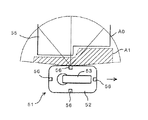
そのため、このシステムでは、図5に示すように、移動ロボット51の無人搬送車52の前後、左右の各辺部の中央部に、移動ロボット51の周囲に設定される検出エリア内への障害物の侵入を検出するための距離測定式のエリアセンサ56を設ける。エリアセンサ56は、検出可能範囲A0内で障害物の検出エリアA1を自在に設定,切替えでき、固定設備55を向く側のエリアセンサ56に関して、その検出エリアA1を固定設備55の凹凸形状に応じて予め設定する。ロボットコントローラは、ロボットアーム53による作業中に、エリアセンサ56により検出エリアA1内への障害物の侵入が検出されたときに、ロボットアーム53を一時停止させるものである。
Therefore, in this system, as shown in FIG. 5, obstacles to the detection area set around the
特許文献2は、天候等の環境状況に左右されることがなく、歩行者を誘導する歩行エリア及びその周辺エリアを移動する物体に対し、歩行者と自動車とを詳細に識別し、歩行者及び特に交通弱者が安全に歩行エリアを渡り終えられるように適切な手段が講じられるようにすることを目的とする。
そのため、この方法では、図6に示すように、横断歩道61と横断歩道61の周辺エリア69とをカバーする検出範囲70に、レーザ感知器72によるエリアセンサによりパルスレーザ光71を投射しながら走査して光の反射時間を計測し、物体Sが存在しない時の反射時間と物体Sが存在する時の反射時間との差を走査各点ごとに求めることにより物体Sの形状と、大きさと、走査ごとの物体Sの位置の変化によるベクトルとを演算し、その演算値から、横断歩道61を誘導方向Pに移動する物体Sと、横断歩道61を横切る方向に移動する物体Sとを識別するものである。
Therefore, in this method, as shown in FIG. 6, scanning is performed while projecting
特許文献1の「移動ロボット及び移動ロボットシステム」は、移動ロボット側にエリアセンサを搭載して,安全機能の向上を図っている。
しかし、移動ロボットに搭載された安全機能は、必ずしも完全ではなく、搭載電源の電圧低下、外部からのノイズ等により誤動作する可能性がある。
そのため、人と同一エリアを移動する従来の移動ロボットは、人の安全性確保のため、人との接近が少ない作業ロボット、例えば掃除ロボット,搬送用台車などが実用化されるにとどまっている。
The “mobile robot and mobile robot system” of
However, the safety function mounted on the mobile robot is not always perfect, and may malfunction due to a voltage drop of the mounted power supply, noise from the outside, or the like.
For this reason, conventional mobile robots that move in the same area as humans have only been put into practical use, such as cleaning robots and transport carts, that are less accessible to humans in order to ensure human safety.
特許文献2の「エリアセンサによる物体識別方法」は、道路交差点における移動物体を識別する方法であり、レーザによるエリアセンサで動いている物体の大きさと速さを検出して,人と車を識別している。
そのため、この方法では、移動ロボットの大きさと速度が、人と同じ程度である場合に、人と移動ロボットの識別ができない問題点があった。
The “object identification method using an area sensor” in
Therefore, in this method, there is a problem that the mobile robot cannot be identified when the size and speed of the mobile robot are the same as those of a human.
さらに現在,実証試験段階であるが,人と同一エリアを移動する移動ロボットの安全性確保のため、イネーブルスイッチを持った監視員(人間)により最終的な安全を確保している。(2005年日本国博覧会(愛知万博)での独立行政法人新エネルギー・産業技術総合開発機構(NEDO)実証試験において実施されている)。 Furthermore, although it is currently in the demonstration test stage, the final safety is secured by a supervisor (human) with an enable switch to ensure the safety of the mobile robot moving in the same area as the human. (It is being carried out in the New Energy and Industrial Technology Development Organization (NEDO) demonstration test at the 2005 Japan Exposition (Aichi Expo)).
本発明は、上述した問題点を解決するために創案されたものである。すなわち、本発明の目的は、人と移動ロボットが同一エリアを移動する場合に、移動ロボットの大きさと速度が人と同じ程度である場合でも人と移動ロボットを確実に識別することができ、移動ロボットの安全機能が誤動作しても監視員なしで人の安全を確保することのできる移動ロボットの監視装置および監視方法を提供することにある。 The present invention has been developed to solve the above-described problems. That is, the object of the present invention is to reliably identify a person and a mobile robot even when the size and speed of the mobile robot are the same as those of a person when the person and the mobile robot move in the same area. It is an object of the present invention to provide a monitoring device and a monitoring method for a mobile robot that can ensure the safety of a person without a supervisor even if the safety function of the robot malfunctions.
本発明によれば、移動ロボットに取り付けられレーザ光を強く反射するリフレクタと、
前記移動ロボットの移動エリアを3次元計測する3次元レーザレーダと、
該3次元レーザレーダによる計測結果から前記移動ロボットと人とを識別し、人と移動ロボットの相対距離が所定の閾値より小さいときに移動ロボットの動作を抑制するロボット抑制装置とを備えた、ことを特徴とする移動ロボットの監視装置が提供される。
According to the present invention, a reflector that is attached to a mobile robot and strongly reflects laser light;
A three-dimensional laser radar that three-dimensionally measures a moving area of the mobile robot;
A robot suppressing device for discriminating between the mobile robot and the person from the measurement result by the three-dimensional laser radar and suppressing the movement of the mobile robot when the relative distance between the person and the mobile robot is smaller than a predetermined threshold; A mobile robot monitoring device is provided.
本発明の好ましい実施形態によれば、前記リフレクタは、一定のパターンで反射率を増減可能な可変反射板である。 According to a preferred embodiment of the present invention, the reflector is a variable reflector that can increase or decrease the reflectance in a constant pattern.
前記可変反射板は、反射強度の強い表面と弱い裏面とを有する強弱反射板と、該強弱反射板を一定のパターンで反転させる反転モータとからなる、ことが好ましい。 The variable reflecting plate is preferably composed of a strong and weak reflecting plate having a surface with a strong reflection intensity and a weak back surface, and a reversing motor for inverting the strong and weak reflecting plate in a certain pattern.
また、前記可変反射板は、反射強度の強い表面を有する強反射板と、該強反射板の表面を一定のパターンで開閉する遮光機構とからなる、ことが好ましい。 Further, it is preferable that the variable reflecting plate includes a strong reflecting plate having a surface with high reflection intensity and a light shielding mechanism for opening and closing the surface of the strong reflecting plate in a certain pattern.
また本発明によれば、(A)レーザ光を強く反射するリフレクタを移動ロボットに取り付け、
(B)3次元レーザレーダにより前記移動ロボットの移動エリアを3次元計測し、
(C)前記3次元計測で得られた3次元データとレーザ光の強度分布から、前記移動ロボットと人とを識別し、人と移動ロボットの相対距離が所定の閾値より小さいときに移動ロボットの動作を抑制する、ことを特徴とする移動ロボットの監視方法が提供される。
According to the present invention, (A) a reflector that strongly reflects laser light is attached to a mobile robot;
(B) Three-dimensional measurement of the moving area of the mobile robot using a three-dimensional laser radar;
(C) The mobile robot and the person are identified from the three-dimensional data obtained by the three-dimensional measurement and the intensity distribution of the laser beam, and when the relative distance between the person and the mobile robot is smaller than a predetermined threshold, There is provided a method for monitoring a mobile robot, characterized by suppressing movement.
本発明の好ましい実施形態によれば、(C1)前記3次元計測で得られた3次元データから固定物を除外し、
(C2)固定物を除外した3次元データから、あらかじめ設定した距離範囲内に存在するデータ同士をグループ分けし、
(C3)各グループの重心を算出し、
(C4)各グループのレーザ反射強度の平均または最大値を算出し、一定閾値以上の場合に移動ロボット、それ以外を人と判定し、
(C5)移動ロボットと人の重心距離が所定の閾値より小さいときに移動ロボットの動作を抑制する。
According to a preferred embodiment of the present invention, (C1) excluding a fixed object from the three-dimensional data obtained by the three-dimensional measurement,
(C2) From the three-dimensional data excluding fixed objects, data existing within a preset distance range are grouped,
(C3) Calculate the center of gravity of each group,
(C4) The average or maximum value of the laser reflection intensity of each group is calculated.
(C5) The movement of the mobile robot is suppressed when the distance between the center of gravity of the mobile robot and the person is smaller than a predetermined threshold.
上記本発明の装置および方法によれば、レーザ光を強く反射するリフレクタを移動ロボットに取り付け、3次元レーザレーダによる3次元計測で得られたレーザ光の強度分布から移動ロボットと人とを識別するので、人と移動ロボットが同一エリアを移動する場合に、移動ロボットの大きさと速度が人と同じ程度である場合でも人と移動ロボットを確実に識別することができる。 According to the apparatus and method of the present invention, the reflector that strongly reflects the laser beam is attached to the mobile robot, and the mobile robot and the person are discriminated from the intensity distribution of the laser beam obtained by the three-dimensional measurement by the three-dimensional laser radar. Therefore, when a person and a mobile robot move in the same area, the person and the mobile robot can be reliably identified even if the size and speed of the mobile robot are about the same as those of the person.
また、3次元計測で得られた3次元データから人と移動ロボットの相対距離が所定の閾値より小さいときに移動ロボットの動作を抑制するので、移動ロボットの安全機能が誤動作しても監視員なしで人の安全を確保することができる。 In addition, since the operation of the mobile robot is suppressed when the relative distance between the person and the mobile robot is smaller than a predetermined threshold from the three-dimensional data obtained by the three-dimensional measurement, there is no supervisor even if the safety function of the mobile robot malfunctions. Can secure human safety.
すなわち本発明では、3次元レーザレーダを用いて、3次元形状の計測とレーザ光が計測対象物に反射して返って来た信号の強度の計測を同時に実行して、人と移動ロボットが混在しているエリアの3次元情報を取得する。
これにより移動ロボットが移動するエリアの3次元情報から人と移動ロボットの位置情報を得るとともに、移動ロボットにはレーザ光を強く反射するリフレクタ(反射板)を取り付けておき、反射の強弱で人か移動ロボットかの区別を行う。
この結果、人と移動ロボットの位置が近接していると判断した場合に、その移動ロボットの動作速度を低下させる。
In other words, in the present invention, a three-dimensional laser radar is used to simultaneously measure a three-dimensional shape and measure the intensity of the signal returned from the reflected laser beam to the object to be measured. The three-dimensional information of the area being acquired is acquired.
As a result, the position information of the person and the mobile robot is obtained from the three-dimensional information of the area where the mobile robot moves, and a reflector (reflector) that strongly reflects the laser beam is attached to the mobile robot. Distinguish between mobile robots.
As a result, when it is determined that the position of the person and the mobile robot is close, the operation speed of the mobile robot is reduced.
これにより、人と移動ロボットが接触する恐れがある場合に、移動ロボットに非常停止をかけた時の空走距離を縮めて、接触を防止することができる。また、万が一接触が発生した場合でも、速度が遅いことにより人がこうむるダメージも低減することができる。
従って、安全性を維持したまま、柵の制約を受けずに移動ロボットの配置を変更することができ、人と移動ロボットを混在・協働させることができる。
As a result, when there is a possibility that a person and the mobile robot come into contact with each other, it is possible to reduce the free running distance when an emergency stop is applied to the mobile robot, thereby preventing contact. Moreover, even if a contact occurs, damage caused by a person due to the slow speed can be reduced.
Accordingly, it is possible to change the arrangement of the mobile robot without being restricted by the fence while maintaining safety, and to mix and cooperate humans and mobile robots.
さらにリフレクタの反射を、一定のパターンでON/OFFすることにより、人か移動ロボットかの区別をするのと同時に、複数ある移動ロボットの区別・特定することも可能である。 Further, by turning ON / OFF the reflection of the reflector in a fixed pattern, it is possible to distinguish between a human and a mobile robot and at the same time distinguish and specify a plurality of mobile robots.
以下、本発明の好ましい実施例を図面を参照して説明する。なお、各図において共通する部分には同一の符号を付し、重複した説明を省略する。 Hereinafter, preferred embodiments of the present invention will be described with reference to the drawings. In addition, the same code | symbol is attached | subjected to the common part in each figure, and the overlapping description is abbreviate | omitted.
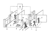
図1は、本発明による人と移動ロボットが同一エリアを移動する共存環境のイメージ図である。
この図において、1は移動ロボット、2は人(人間)、3は床面、4は床面に置かれた固定物である。
このロボットと人の共存環境において、移動ロボット1はワイヤレスラン等でそれぞれ個別に制御され、人と同一エリアを移動しながら予め定められた作業を行う。また、各移動ロボット1は、人との接触を回避する安全機能をそれぞれ搭載している。
この共存環境において、人2は、例えば作業員であり、移動ロボット1と同一エリアを移動しながら種々の作業を行う。
この例において、移動ロボット1の大きさと速度は、人2と同じ程度であるものとする。しかし、本発明はこれに限定される、大きさと速度が大きく相違してもよい。
FIG. 1 is an image diagram of a coexistence environment in which a person and a mobile robot according to the present invention move in the same area.
In this figure, 1 is a mobile robot, 2 is a person (human), 3 is a floor surface, and 4 is a fixed object placed on the floor surface.
In this robot-human coexistence environment, the
In this coexistence environment, the
In this example, it is assumed that the size and speed of the
図2は、本発明による移動ロボットの監視装置の構成図である。この図は、図1のあるエリアを上方から見た平面図である。
この図において、本発明の監視装置10は、リフレクタ12、3次元レーザレーダ14及びロボット抑制装置16を備える。
FIG. 2 is a block diagram of a monitoring apparatus for a mobile robot according to the present invention. This figure is a plan view of an area in FIG. 1 as viewed from above.
In this figure, a
リフレクタ12は、移動ロボット1に取り付けられレーザ光を強く反射する反射板である。このリフレクタ12は、一定のパターンで反射率を増減可能な可変反射板であるのがよい。
この可変反射板は、例えば、反射強度の強い表面と弱い裏面とを有する強弱反射板と、強弱反射板を一定のパターンで反転させる反転モータとからなる。
また可変反射板は、反射強度の強い表面を有する強反射板と、強反射板の表面を一定のパターンで開閉する遮光機構とから構成してもよい。
The
This variable reflector includes, for example, a strong and weak reflector having a front surface having a high reflection intensity and a weak back surface, and a reversing motor that reverses the strong and weak reflector in a fixed pattern.
The variable reflecting plate may be composed of a strong reflecting plate having a surface with high reflection intensity and a light shielding mechanism that opens and closes the surface of the strong reflecting plate in a certain pattern.
3次元レーザレーダ14は、移動ロボット1の移動エリアを3次元計測する。
ロボット抑制装置16は、例えばコンピュータ(PC)であり、3次元レーザレーダ14による計測結果から移動ロボット1と人2とを識別し、人と移動ロボットの相対距離が所定の閾値より小さいときに移動ロボットの動作を抑制する。
この例では、4台の3次元レーザレーダ14がそれぞれ半円形の破線で示す範囲を3次元計測し、この図の矩形領域をカバーして計測するようになっている。
The three-
The
In this example, the four three-
図3は、3次元レーザレーダの原理図である。この図において、(A)は3次元レーザレーダと計測対象物との関係図、(B)は照射光と反射光のデータ例、(C)は2次元スキャンのイメージ図である。
図3(A)(B)に示すように、3次元レーザレーダ14では、パルス状または変調をかけたレーザ光を照射光6として照射し、計測対象物7で反射して戻ってくる反射光8までの時間差Δtを計ることにより計測対象物7までの距離値と、反射光8を光学センサで受けた時の波形振幅から受光強度とをそれぞれ計測することができる。
また図3(C)に示すように、この照射光6を上下左右に2次元的にスキャンすることにより、計測対象物7の3次元形状と反射強度の情報を得ることができる。
FIG. 3 is a principle diagram of a three-dimensional laser radar. In this figure, (A) is a relationship diagram between a three-dimensional laser radar and a measurement object, (B) is a data example of irradiation light and reflected light, and (C) is an image diagram of a two-dimensional scan.
As shown in FIGS. 3A and 3B, the three-
Further, as shown in FIG. 3C, information of the three-dimensional shape and reflection intensity of the
3次元レーザデータ14による計測結果は、ヨー方向の角度θ、ピッチ方向の角度φ、距離D、受光強度Mを一組としたデータ列となる。θ、φ、Dから、計測対象物7の3次元座標X、Y、Zを算出可能である。
The measurement result by the three-
図4は、本発明による移動ロボットの監視方法の説明図である。
図4(A)は、3次元レーザレーダ14により移動ロボット1の移動エリアを3次元計測して得られた3次元データの模式図である。
FIG. 4 is an explanatory diagram of a mobile robot monitoring method according to the present invention.
FIG. 4A is a schematic diagram of three-dimensional data obtained by three-dimensionally measuring the moving area of the
図4(B)では、得られた3次元データから床面3やフェンス等の固定物4を除外する。この除外は、人2や移動ロボット1が存在しない状態で3次元レーザレーダにより計測した結果を背景情報として記録しておき、人や移動ロボットを含む計測結果から差し引く手段や、あらかじめ床面からの高さが数十センチ以内、フェンスからの幅、高さ方向の距離が数十センチ以内といった不感帯を設定しておき、計測結果中で不感帯の範囲に含まれるデータを削除する手段などで実行することができる。
In FIG. 4B, the fixed
図4(C)では、固定物を除外した3次元データから、それぞれあらかじめ設定した距離範囲内に存在するデータ同士をグループ分けする。
図4(D)では、各グループの重心を算出する等の手段で、計測された物体の位置を算出する。この重心算出において、各グループの背面形状が不明な場合には、これを平面または正面形状で模擬してもよい。
In FIG. 4C, data existing within a predetermined distance range is grouped from the three-dimensional data excluding fixed objects.
In FIG. 4D, the position of the measured object is calculated by means such as calculating the center of gravity of each group. In the calculation of the center of gravity, when the back shape of each group is unknown, this may be simulated by a flat or front shape.
図4(E)では、各グループにレーザ反射強度の平均または最大値を算出し、一定閾値以上の場合に移動ロボット、それ以外を人と判定する。レーザの反射強度は算出値のまま用いてもよいし、反射強度が距離の自乗に反比例するという特性から、距離値により補正をかけてから用いてもよい。 In FIG. 4E, the average or maximum value of the laser reflection intensity is calculated for each group, and a mobile robot is determined if it is equal to or greater than a certain threshold value, and the other is determined as a person. The reflection intensity of the laser may be used as it is, or may be used after being corrected by the distance value because the reflection intensity is inversely proportional to the square of the distance.
図4(F)では、人と移動ロボットとがあらかじめ設定した距離以内に近づいた場合、当該移動ロボットに対し、動作速度を低下させるなどの指令を与える。すなわち、移動ロボットと人の重心距離が所定の閾値より小さいときに移動ロボットの動作を抑制する。
この移動ロボットの動作抑制は、例えば移動ロボットを制御するワイヤレスランとは別個の無線指令ラインを冗長的に設け、この無線指令ラインでそれぞれ該当する移動ロボットを制御するのがよい。
In FIG. 4F, when a person and the mobile robot are within a preset distance, a command to reduce the operation speed is given to the mobile robot. That is, the movement of the mobile robot is suppressed when the distance between the center of gravity of the mobile robot and the person is smaller than a predetermined threshold.
In order to suppress the movement of the mobile robot, for example, it is preferable to redundantly provide a radio command line separate from a wireless run for controlling the mobile robot, and to control the corresponding mobile robot using the radio command line.
上述したように、本発明では、人か移動ロボットかを区別するために、移動ロボット1にリフレクタ12を取り付ける。リフレクタ12は、これを反射強度の強い表面と弱い裏面とを一定のパターンで反転させ、或いは、リフレクタ表面にシャッター等の遮光機構を設け一定のパターンで開閉することにより、3次元レーザレーダ14で移動ロボット1を区別・特定するための情報を提供することが可能である。
As described above, in the present invention, the
たとえば、移動ロボットAと移動ロボットBの2台が存在する時、Aは1秒周期でリフレクタの反射をON→ON→OFF→OFFというパターンを繰り返し、BではON→ON→OFF→ONと繰り返させることにより、信号強度を計測した3次元レーザレーダでAとBを区別することができる。 For example, when there are two mobile robots A and B, A repeats the pattern of reflector reflection ON → ON → OFF → OFF in 1 second cycle, and B repeats ON → ON → OFF → ON. By doing so, A and B can be distinguished by a three-dimensional laser radar that measures the signal intensity.
または、3次元レーザレーダ側から無線等を使って各移動ロボットに個別に呼びかけを行い、呼ばれた移動ロボットだけがリフレクタをONすることによっても移動ロボットを特定することが可能である。 Alternatively, it is possible to specify a mobile robot by calling each mobile robot individually from the 3D laser radar side using wireless or the like, and only the called mobile robot turns on the reflector.
なお、本発明において、「移動ロボット」とは、自走可能なロボットを意味する。しかし、本発明は、固定配置されているロボットにも適用でき、この場合は、3次元レーザレーダ側であらかじめ各ロボットの位置を記憶していれば良い。また、ロボットが走行する場合には、本発明によりどの移動ロボットが人と接近しており、どの移動ロボットに速度低下を指示すればよいかを特定することができる。 In the present invention, the “mobile robot” means a robot that can run on its own. However, the present invention can also be applied to a fixedly arranged robot. In this case, the position of each robot may be stored in advance on the three-dimensional laser radar side. Further, when the robot travels, the present invention can specify which mobile robot is approaching a person and which mobile robot should be instructed to decrease the speed.
上述したように、本発明の装置および方法によれば、レーザ光を強く反射するリフレクタ12を移動ロボット1に取り付け、3次元レーザレーダ14による3次元計測で得られたレーザ光の強度分布から移動ロボット1と人2とを識別するので、人と移動ロボットが同一エリアを移動する場合に、移動ロボット1の大きさと速度が人2と同じ程度である場合でも人と移動ロボットを確実に識別することができる。
As described above, according to the apparatus and method of the present invention, the
また、3次元計測で得られた3次元データから人2と移動ロボット1の相対距離が所定の閾値より小さいときに移動ロボットの動作を抑制するので、移動ロボットの安全機能が誤動作しても監視員なしで人の安全を確保することができる。
In addition, since the movement of the mobile robot is suppressed when the relative distance between the
すなわち本発明では、3次元レーザレーダ14を用いて、3次元形状の計測とレーザ光が計測対象物に反射して返って来た信号の強度の計測を同時に実行して、人2と移動ロボット1が混在しているエリアの3次元情報を取得する。
これによりエリアの3次元情報から人2と移動ロボット1の位置情報を得るとともに、移動ロボット1にはレーザ光を強く反射するリフレクタ12(反射板)を取り付けておき、反射の強弱で人か移動ロボットかの区別を行う。
この結果、人と移動ロボットの位置が近接していると判断した場合に、その移動ロボットの動作速度を低下させる。
In other words, in the present invention, the three-
As a result, the position information of the
As a result, when it is determined that the position of the person and the mobile robot is close, the operation speed of the mobile robot is reduced.
これにより、人と移動ロボットが接触する恐れがある場合に、移動ロボットに非常停止をかけた時の空走距離を縮めて、接触を防止することができる。また、万が一接触が発生した場合でも、速度が遅いことにより人がこうむるダメージも低減することができる。
従って、安全性を維持したまま、柵の制約を受けずに移動ロボットの配置を変更することができ、人と移動ロボットを混在・協働させることができる。
As a result, when there is a possibility that a person and the mobile robot come into contact with each other, it is possible to reduce the free running distance when an emergency stop is applied to the mobile robot, thereby preventing contact. Moreover, even if a contact occurs, damage caused by a person due to the slow speed can be reduced.
Accordingly, it is possible to change the arrangement of the mobile robot without being restricted by the fence while maintaining safety, and to mix and cooperate humans and mobile robots.
さらにリフレクタの反射を、一定のパターンでON/OFFすることにより、人か移動ロボットかの区別をするのと同時に、複数ある移動ロボットの区別・特定することも可能である。 Further, by turning ON / OFF the reflection of the reflector in a fixed pattern, it is possible to distinguish between a human and a mobile robot and at the same time distinguish and specify a plurality of mobile robots.
なお、本発明は、上述した実施形態に限定されず、本発明の要旨を逸脱しない範囲で種々に変更することができることは勿論である。 In addition, this invention is not limited to embodiment mentioned above, Of course, it can change variously in the range which does not deviate from the summary of this invention.
1 移動ロボット、2 人(人間)、3 床面、4 固定物、
6 照射光、7 計測対象物、8 反射光、
10 監視装置、12 リフレクタ(反射板)、
14 3次元レーザレーダ、16 ロボット抑制装置
1 mobile robot, 2 people (human), 3 floor, 4 fixed object,
6 Irradiation light, 7 Measurement object, 8 Reflected light,
10 monitoring device, 12 reflector (reflector),
14 Three-dimensional laser radar, 16 Robot restraint device
Claims (2)
前記移動ロボットの移動エリアを3次元計測する3次元レーザレーダと、
該3次元レーザレーダによる計測結果から前記移動ロボットと人とを識別し、人と移動ロボットの相対距離が所定の閾値より小さいときに移動ロボットの動作を抑制するロボット抑制装置とを備え、
(C1)前記3次元計測で得られた3次元データから固定物を除外し、
(C2)固定物を除外した3次元データから、あらかじめ設定した距離範囲内に存在するデータ同士をグループ分けし、
(C3)各グループの重心を算出し、
(C4)各グループのレーザ反射強度の平均を算出し、一定閾値以上の場合に移動ロボット、それ以外を人と判定し、
(C5)移動ロボットと人の重心距離が所定の閾値より小さいときに移動ロボットの動作を抑制する、ことを特徴とする移動ロボットの監視装置。 A reflector attached to the mobile robot that strongly reflects the laser beam;
A three-dimensional laser radar that three-dimensionally measures a moving area of the mobile robot;
Distinguish between humans and the mobile robot from the measurement result by the three-dimensional laser radar, Bei example and suppressing robot suppression device the operation of the mobile robot when the relative distance of the person and the mobile robot is smaller than a predetermined threshold value,
(C1) A fixed object is excluded from the three-dimensional data obtained by the three-dimensional measurement,
(C2) From the three-dimensional data excluding fixed objects, data existing within a preset distance range are grouped,
(C3) Calculate the center of gravity of each group,
(C4) Calculate the average of the laser reflection intensity of each group, and determine that the robot is a mobile robot if it is equal to or greater than a certain threshold, and the other is a person
(C5) A mobile robot monitoring device, characterized in that the mobile robot operation is suppressed when the distance between the center of gravity of the mobile robot and the person is smaller than a predetermined threshold .
(B)3次元レーザレーダにより前記移動ロボットの移動エリアを3次元計測し、
(C)前記3次元計測で得られた3次元データとレーザ光の強度分布から、前記移動ロボットと人とを識別し、人と移動ロボットの相対距離が所定の閾値より小さいときに移動ロボットの動作を抑制する場合に、
(C1)前記3次元計測で得られた3次元データから固定物を除外し、
(C2)固定物を除外した3次元データから、あらかじめ設定した距離範囲内に存在するデータ同士をグループ分けし、
(C3)各グループの重心を算出し、
(C4)各グループのレーザ反射強度の平均を算出し、一定閾値以上の場合に移動ロボット、それ以外を人と判定し、
(C5)移動ロボットと人の重心距離が所定の閾値より小さいときに移動ロボットの動作を抑制する、ことを特徴とする移動ロボットの監視方法。 (A) A reflector that strongly reflects laser light is attached to the mobile robot,
(B) Three-dimensional measurement of the moving area of the mobile robot using a three-dimensional laser radar;
(C) The mobile robot and the person are identified from the three-dimensional data obtained by the three-dimensional measurement and the intensity distribution of the laser beam, and when the relative distance between the person and the mobile robot is smaller than a predetermined threshold, When suppressing the operation ,
(C1) A fixed object is excluded from the three-dimensional data obtained by the three-dimensional measurement,
(C2) From the three-dimensional data excluding fixed objects, data existing within a preset distance range are grouped,
(C3) Calculate the center of gravity of each group,
(C4) Calculate the average of the laser reflection intensity of each group, and determine that the robot is a mobile robot if it is equal to or greater than a certain threshold, and the other is a person
(C5) A method for monitoring a mobile robot, characterized in that the operation of the mobile robot is suppressed when the distance between the center of gravity of the mobile robot and the person is smaller than a predetermined threshold .
Priority Applications (1)
| Application Number | Priority Date | Filing Date | Title |
|---|---|---|---|
| JP2008002853A JP5190761B2 (en) | 2008-01-10 | 2008-01-10 | MOBILE ROBOT MONITORING DEVICE AND MONITORING METHOD |
Applications Claiming Priority (1)
| Application Number | Priority Date | Filing Date | Title |
|---|---|---|---|
| JP2008002853A JP5190761B2 (en) | 2008-01-10 | 2008-01-10 | MOBILE ROBOT MONITORING DEVICE AND MONITORING METHOD |
Publications (2)
| Publication Number | Publication Date |
|---|---|
| JP2009162709A JP2009162709A (en) | 2009-07-23 |
| JP5190761B2 true JP5190761B2 (en) | 2013-04-24 |
Family
ID=40965480
Family Applications (1)
| Application Number | Title | Priority Date | Filing Date |
|---|---|---|---|
| JP2008002853A Active JP5190761B2 (en) | 2008-01-10 | 2008-01-10 | MOBILE ROBOT MONITORING DEVICE AND MONITORING METHOD |
Country Status (1)
| Country | Link |
|---|---|
| JP (1) | JP5190761B2 (en) |
Families Citing this family (12)
| Publication number | Priority date | Publication date | Assignee | Title |
|---|---|---|---|---|
| DE112011103155T5 (en) * | 2010-09-21 | 2013-07-18 | Toyota Jidosha Kabushiki Kaisha | Mobile body |
| JP5481358B2 (en) * | 2010-11-29 | 2014-04-23 | 本田技研工業株式会社 | POSITION INFORMATION CONTROL SYSTEM, POSITION INFORMATION CONTROL DEVICE, POSITION INFORMATION CONTROL METHOD, AND POSITION INFORMATION CONTROL PROGRAM |
| JP5595354B2 (en) * | 2011-08-01 | 2014-09-24 | 大成建設株式会社 | Position confirmation system |
| JP5377689B2 (en) | 2011-09-21 | 2013-12-25 | 斎藤 光正 | LED lighting fixture with built-in standing wave radar |
| JP2014188645A (en) * | 2013-03-28 | 2014-10-06 | Seiko Epson Corp | Robot group system |
| JP6153434B2 (en) * | 2013-09-26 | 2017-06-28 | オリンパス株式会社 | Cell observation information processing system, cell observation information processing method, cell observation information processing program, recording unit provided in cell observation information processing system, device provided in cell observation information processing system |
| WO2017033360A1 (en) * | 2015-08-25 | 2017-03-02 | 川崎重工業株式会社 | Remote control manipulator system and operation method thereof |
| JP6695169B2 (en) * | 2016-02-29 | 2020-05-20 | 大同信号株式会社 | Fail-safe method of crossing obstacle detection device |
| JP7392963B2 (en) * | 2017-09-05 | 2023-12-06 | 日本電気株式会社 | Spatial recognition device, spatial recognition method, program |
| JP7135496B2 (en) | 2018-06-26 | 2022-09-13 | セイコーエプソン株式会社 | 3D measuring device, control device and robot system |
| JP7346997B2 (en) * | 2019-08-21 | 2023-09-20 | オムロン株式会社 | Robot control device, robot control method, and program |
| CN116501070B (en) * | 2023-06-30 | 2023-09-19 | 深圳市欢创科技有限公司 | Recharging method, robot and storage medium |
Family Cites Families (5)
| Publication number | Priority date | Publication date | Assignee | Title |
|---|---|---|---|---|
| JP2003105807A (en) * | 2001-09-27 | 2003-04-09 | Komatsu Ltd | Stop control method in intrusion-prohibitive region for service car and its controller |
| DE10152543A1 (en) * | 2001-10-24 | 2003-05-08 | Sick Ag | Method and device for controlling a safety-relevant function of a machine |
| JP2004325272A (en) * | 2003-04-25 | 2004-11-18 | Nippon Telegr & Teleph Corp <Ntt> | Positioning system, terminal, base station and information providing system |
| JP4069926B2 (en) * | 2005-01-11 | 2008-04-02 | 株式会社Ihi | Object detection device |
| JP4871034B2 (en) * | 2006-06-14 | 2012-02-08 | 富士通株式会社 | Radar device and reflection device |
-
2008
- 2008-01-10 JP JP2008002853A patent/JP5190761B2/en active Active
Also Published As
| Publication number | Publication date |
|---|---|
| JP2009162709A (en) | 2009-07-23 |
Similar Documents
| Publication | Publication Date | Title |
|---|---|---|
| JP5190761B2 (en) | MOBILE ROBOT MONITORING DEVICE AND MONITORING METHOD | |
| CN108490447B (en) | Anti-pinch system and method for platform door and train | |
| JP6601155B2 (en) | Robot control system | |
| US20210171324A1 (en) | Engineering machinery and dynamic anti-collision method, device, and system for operation space of the engineering machinery | |
| EP2506106B1 (en) | Autonomous moving object and control method | |
| JP4701290B2 (en) | Radiation imaging inspection method and radiation imaging inspection system for moving body | |
| CN103269914B (en) | The automatic method of operating of vehicle closure member and corresponding equipment and the vehicle | |
| US9804605B2 (en) | Position identification device and mobile robot provided with same | |
| ES2634684T3 (en) | Device to aid the operation of a crane | |
| CN110461753A (en) | Method and apparatus for monitoring elevator cab door | |
| JP6828579B2 (en) | Environmental maintenance robot and its control program | |
| CN107000766A (en) | Door system with the sensor unit for contactless passenger carriage monitoring | |
| JP5963400B2 (en) | Method and apparatus for detecting train stop position | |
| JP2013131100A (en) | Number of persons prediction method, number of persons prediction device, movable robot, and program | |
| JP2013527423A (en) | Method and apparatus for measuring the spatial expansion of an object | |
| JP6187499B2 (en) | Self-localization method for autonomous mobile robot, autonomous mobile robot, and landmark for self-localization | |
| KR101962403B1 (en) | An Apparatus and A Method For Stop Guidance In Position Based On Phased-Array Optical Beams | |
| JP4561499B2 (en) | Vehicle driving support device | |
| US20220119229A1 (en) | Crane anti-collision system, method, program, and manufacturing method | |
| KR20220146617A (en) | Method and apparatus for detecting blooming in lidar measurements | |
| KR101710131B1 (en) | Apparatus for measuring displacement of tunnal | |
| CN113085848B (en) | Control method and device for unmanned road roller, electronic equipment and storage medium | |
| CN113734207B (en) | Vehicle safety protection system and method and vehicle | |
| JP6187500B2 (en) | Self-localization method for autonomous mobile robot, autonomous mobile robot, and landmark for self-localization | |
| Bostelman et al. | Safe control of manufacturing vehicles research towards standard test methods |
Legal Events
| Date | Code | Title | Description |
|---|---|---|---|
| A621 | Written request for application examination |
Free format text: JAPANESE INTERMEDIATE CODE: A621 Effective date: 20101125 |
|
| A977 | Report on retrieval |
Free format text: JAPANESE INTERMEDIATE CODE: A971007 Effective date: 20121010 |
|
| A131 | Notification of reasons for refusal |
Free format text: JAPANESE INTERMEDIATE CODE: A131 Effective date: 20121012 |
|
| A521 | Written amendment |
Free format text: JAPANESE INTERMEDIATE CODE: A523 Effective date: 20121211 |
|
| TRDD | Decision of grant or rejection written | ||
| A01 | Written decision to grant a patent or to grant a registration (utility model) |
Free format text: JAPANESE INTERMEDIATE CODE: A01 Effective date: 20130107 |
|
| A61 | First payment of annual fees (during grant procedure) |
Free format text: JAPANESE INTERMEDIATE CODE: A61 Effective date: 20130120 |
|
| R151 | Written notification of patent or utility model registration |
Ref document number: 5190761 Country of ref document: JP Free format text: JAPANESE INTERMEDIATE CODE: R151 |
|
| FPAY | Renewal fee payment (event date is renewal date of database) |
Free format text: PAYMENT UNTIL: 20160208 Year of fee payment: 3 |
|
| R250 | Receipt of annual fees |
Free format text: JAPANESE INTERMEDIATE CODE: R250 |
|
| R250 | Receipt of annual fees |
Free format text: JAPANESE INTERMEDIATE CODE: R250 |