WO2009107358A1 - Control apparatus and control method for a robot arm, robot, control program for a robot arm, and electronic integrated circuit for controlling a robot arm - Google Patents
Control apparatus and control method for a robot arm, robot, control program for a robot arm, and electronic integrated circuit for controlling a robot arm Download PDFInfo
- Publication number
- WO2009107358A1 WO2009107358A1 PCT/JP2009/000783 JP2009000783W WO2009107358A1 WO 2009107358 A1 WO2009107358 A1 WO 2009107358A1 JP 2009000783 W JP2009000783 W JP 2009000783W WO 2009107358 A1 WO2009107358 A1 WO 2009107358A1
- Authority
- WO
- WIPO (PCT)
- Prior art keywords
- robot arm
- information
- correction
- unit
- motion
- Prior art date
Links
Images


Classifications
-
- B—PERFORMING OPERATIONS; TRANSPORTING
- B25—HAND TOOLS; PORTABLE POWER-DRIVEN TOOLS; MANIPULATORS
- B25J—MANIPULATORS; CHAMBERS PROVIDED WITH MANIPULATION DEVICES
- B25J13/00—Controls for manipulators
- B25J13/08—Controls for manipulators by means of sensing devices, e.g. viewing or touching devices
- B25J13/085—Force or torque sensors
-
- B—PERFORMING OPERATIONS; TRANSPORTING
- B25—HAND TOOLS; PORTABLE POWER-DRIVEN TOOLS; MANIPULATORS
- B25J—MANIPULATORS; CHAMBERS PROVIDED WITH MANIPULATION DEVICES
- B25J9/00—Programme-controlled manipulators
- B25J9/16—Programme controls
- B25J9/1628—Programme controls characterised by the control loop
- B25J9/1633—Programme controls characterised by the control loop compliant, force, torque control, e.g. combined with position control
-
- G—PHYSICS
- G05—CONTROLLING; REGULATING
- G05B—CONTROL OR REGULATING SYSTEMS IN GENERAL; FUNCTIONAL ELEMENTS OF SUCH SYSTEMS; MONITORING OR TESTING ARRANGEMENTS FOR SUCH SYSTEMS OR ELEMENTS
- G05B19/00—Programme-control systems
- G05B19/02—Programme-control systems electric
- G05B19/42—Recording and playback systems, i.e. in which the programme is recorded from a cycle of operations, e.g. the cycle of operations being manually controlled, after which this record is played back on the same machine
- G05B19/423—Teaching successive positions by walk-through, i.e. the tool head or end effector being grasped and guided directly, with or without servo-assistance, to follow a path
-
- G—PHYSICS
- G05—CONTROLLING; REGULATING
- G05B—CONTROL OR REGULATING SYSTEMS IN GENERAL; FUNCTIONAL ELEMENTS OF SUCH SYSTEMS; MONITORING OR TESTING ARRANGEMENTS FOR SUCH SYSTEMS OR ELEMENTS
- G05B2219/00—Program-control systems
- G05B2219/30—Nc systems
- G05B2219/36—Nc in input of data, input key till input tape
- G05B2219/36418—Modify trajectory by operator gesture, gesture force sensed by end effector
-
- G—PHYSICS
- G05—CONTROLLING; REGULATING
- G05B—CONTROL OR REGULATING SYSTEMS IN GENERAL; FUNCTIONAL ELEMENTS OF SUCH SYSTEMS; MONITORING OR TESTING ARRANGEMENTS FOR SUCH SYSTEMS OR ELEMENTS
- G05B2219/00—Program-control systems
- G05B2219/30—Nc systems
- G05B2219/36—Nc in input of data, input key till input tape
- G05B2219/36432—By putting some constraints on some DOF, move within limited volumes, areas, planes, limits motion in x, y or z planes, virtual reality constraints
-
- G—PHYSICS
- G05—CONTROLLING; REGULATING
- G05B—CONTROL OR REGULATING SYSTEMS IN GENERAL; FUNCTIONAL ELEMENTS OF SUCH SYSTEMS; MONITORING OR TESTING ARRANGEMENTS FOR SUCH SYSTEMS OR ELEMENTS
- G05B2219/00—Program-control systems
- G05B2219/30—Nc systems
- G05B2219/36—Nc in input of data, input key till input tape
- G05B2219/36489—Position and force
-
- G—PHYSICS
- G05—CONTROLLING; REGULATING
- G05B—CONTROL OR REGULATING SYSTEMS IN GENERAL; FUNCTIONAL ELEMENTS OF SUCH SYSTEMS; MONITORING OR TESTING ARRANGEMENTS FOR SUCH SYSTEMS OR ELEMENTS
- G05B2219/00—Program-control systems
- G05B2219/30—Nc systems
- G05B2219/37—Measurements
- G05B2219/37357—Force, pressure, weight or deflection
-
- G—PHYSICS
- G05—CONTROLLING; REGULATING
- G05B—CONTROL OR REGULATING SYSTEMS IN GENERAL; FUNCTIONAL ELEMENTS OF SUCH SYSTEMS; MONITORING OR TESTING ARRANGEMENTS FOR SUCH SYSTEMS OR ELEMENTS
- G05B2219/00—Program-control systems
- G05B2219/30—Nc systems
- G05B2219/39—Robotics, robotics to robotics hand
- G05B2219/39325—External force control, additional loop comparing forces corrects position
-
- G—PHYSICS
- G05—CONTROLLING; REGULATING
- G05B—CONTROL OR REGULATING SYSTEMS IN GENERAL; FUNCTIONAL ELEMENTS OF SUCH SYSTEMS; MONITORING OR TESTING ARRANGEMENTS FOR SUCH SYSTEMS OR ELEMENTS
- G05B2219/00—Program-control systems
- G05B2219/30—Nc systems
- G05B2219/39—Robotics, robotics to robotics hand
- G05B2219/39343—Force based impedance control
-
- G—PHYSICS
- G05—CONTROLLING; REGULATING
- G05B—CONTROL OR REGULATING SYSTEMS IN GENERAL; FUNCTIONAL ELEMENTS OF SUCH SYSTEMS; MONITORING OR TESTING ARRANGEMENTS FOR SUCH SYSTEMS OR ELEMENTS
- G05B2219/00—Program-control systems
- G05B2219/30—Nc systems
- G05B2219/40—Robotics, robotics mapping to robotics vision
- G05B2219/40411—Robot assists human in non-industrial environment like home or office
Definitions
- the present invention relates to a robot arm control device and control method for generating and teaching a robot motion, a robot having a robot arm control device, a robot arm program, and an integrated electronic circuit for robot arm control.
- home robots such as care robots or housework support robots have been actively developed. Unlike an industrial robot, a home robot is operated by an amateur at home, so it needs to be able to easily teach the operation. Furthermore, since the operating environment when the robot is working varies depending on the home, it is necessary to flexibly cope with the home environment.
- a force sensor is attached to the wrist of the robot, the teacher directly holds the handle attached to the tip of the force sensor, and the robot is guided to the teaching point to teach the robot position. (See Patent Document 1 and Patent Document 2).
- Patent Document 1 since it is necessary for the teacher to teach all the teaching points, the teaching takes time and is very troublesome. Furthermore, in the industrial field, when correcting a part of the taught movement, it must be corrected by programming with a remote device called a teaching pendant, or all operations must be taught from the beginning. Was bad.
- the object of the present invention has been made in view of such problems, and is adapted to the environment in which the robot arm operates, and further, robot control that enables the operator to teach the robot in a short time.
- a robot arm control apparatus and method a robot, a robot arm control program, and an integrated electronic circuit for controlling a robot arm.
- the present invention is configured as follows.
- a control device for a robot arm that controls the operation of the robot arm
- the motion information is acquired from a motion information database in which at least one of the position, posture, and speed of the robot arm corresponding to the motion is stored as motion information in time series, and a person
- a position control unit for controlling the robot arm to move based on the motion information An operation correction unit that corrects the operation information according to the correction operation information at each time acquired by the information acquisition unit while the robot arm is moving while being controlled by the position control unit.
- a robot arm control device that controls the movement of the robot arm based on the movement information corrected by the movement correction unit.
- a robot arm control method for controlling an operation of a robot arm
- the information acquisition unit acquires the information from the operation information database in which at least one of the position, posture, and speed of the robot arm corresponding to the operation is stored as operation information in time series.
- the information acquisition unit acquires at least one correction operation information of the position, posture, and speed of the robot arm when correcting the operation of the robot arm
- the position control unit controls the robot arm to move based on the operation information
- the operation information is corrected by the operation correction unit according to the correction operation information at each time acquired by the information acquisition unit
- a robot arm control method is provided that controls the movement of the robot arm based on the movement information corrected by the movement correction unit.
- the robot arm comprising the robot arm control device according to any one of the first to 25th aspects for controlling the robot arm.
- a robot arm control program for controlling the operation of the robot arm
- the information acquisition unit acquires the information from the operation information database in which at least one of the position, posture, and speed of the robot arm corresponding to the operation is stored as operation information in time series.
- the information acquisition unit acquires at least one correction operation information of the position, posture and speed of the robot arm when correcting the operation of the robot arm, Controlling the robot arm with a position controller to move based on the motion information; While the robot arm is moving while being controlled by the position control unit, the operation correction unit corrects the operation information according to the correction operation information at each time acquired by the information acquisition unit.
- a robot arm control program for executing a step of controlling the movement of the robot arm based on the movement information corrected by the movement correction unit is provided.
- an integrated electronic circuit for controlling the operation of the robot arm The motion information is acquired from a motion information database in which at least one of the position, posture, and speed of the robot arm corresponding to the motion is stored as motion information in time series, and a person To obtain at least one correction operation information of the position, posture and speed of the robot arm when correcting the operation of the robot arm, A position control unit for controlling the robot arm to move based on the motion information; An operation correction unit that corrects the operation information according to the correction operation information at each time acquired by the information acquisition unit while the robot arm is moving while being controlled by the position control unit. And An integrated electronic circuit for controlling a robot arm is provided, wherein the operation of the robot arm is controlled based on the motion information corrected by the motion correction unit.
- the robot arm control device includes the motion information database, the force detection unit, and the motion correction unit. It is possible to control the robot arm that can easily correct the operation of the robot arm according to the force of the person.
- the robot arm control device further includes operation template information, environment information, correction parameter information, and the like, so that the robot arm operation can be easily generated, and in addition, specified by the correction parameter. Only the corrected parameters can be corrected.
- the robot operation described in the operation information can be easily performed according to human power. Robot control that can be corrected becomes possible.
- FIG. 1 is a diagram showing an outline of a configuration of a robot arm control device and a robot arm that is a control target that constitute a robot system according to a first embodiment of the present invention.
- FIG. 2A is a diagram illustrating a detailed configuration of a robot arm control device and a robot arm that is a control target that configure the robot system according to the first embodiment of the present invention;
- FIG. 2B is a diagram illustrating a detailed configuration of a robot arm control device and a robot arm that is a control target that configure a robot system according to a modification of the first embodiment of the present invention;
- FIG. 1 is a diagram showing an outline of a configuration of a robot arm control device and a robot arm that is a control target that constitute a robot system according to a first embodiment of the present invention.
- FIG. 2A is a diagram illustrating a detailed configuration of a robot arm control device and a robot arm that is a control target that configure the robot system according to the first embodiment of the present invention
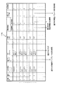
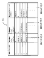
- FIG. 3 is a diagram illustrating a list of operation information in the operation information database of the robot arm control device according to the first embodiment.
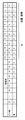
- FIG. 4 is a diagram illustrating flag information in the operation information database of the robot arm control device according to the first embodiment.
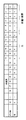
- FIG. 5 is a diagram illustrating correction parameter flag information in the operation information database of the robot arm control device according to the first embodiment.
- FIG. 6 is a diagram illustrating a list of information stored in the operation selection unit of the robot arm control device according to the first embodiment.
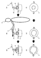
- FIG. 7 is an explanatory diagram for explaining an operation state and a human operation state of the robot arm control device according to the first embodiment of the present invention.
- FIG. 8A to 8C are explanatory diagrams for explaining the operation state, operation state, and operation state of the robot arm control device according to the first embodiment of the present invention, respectively.
- FIG. 9 is a diagram illustrating the display unit of the peripheral device of the robot system according to the first embodiment of the present invention.
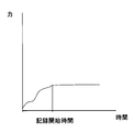
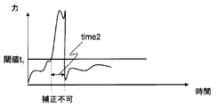
- FIG. 10 is a graph showing the relationship between the force applied by a person and the time in the first embodiment.
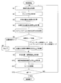
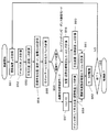
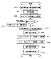
- FIG. 11 is a flowchart showing operation steps of an operation correction unit, an operation selection unit, a correction method setting unit, an operation storage unit, an operation information database, and a control parameter management unit of the robot arm control apparatus according to the first embodiment of the present invention.
- FIG. 9 is a diagram illustrating the display unit of the peripheral device of the robot system according to the first embodiment of the present invention.
- FIG. 10 is a graph showing the relationship between the force applied by a person and the time in the first embodiment.
- FIG. 11 is a flowchart showing operation steps of an operation correction unit, an operation selection unit,
- FIG. 12 is a block diagram illustrating a configuration of a control unit of the robot arm control device according to the first embodiment of the present invention.
- FIG. 13 is a flowchart showing the operation steps of the control unit of the control device for the robot arm in the first embodiment of the present invention
- FIG. 14A is a diagram illustrating an operation state of the robot arm control device according to the second embodiment of the present invention
- FIG. 14B is a diagram illustrating an operation state of the control device for the robot arm according to the second embodiment of the present invention
- FIG. 15 is a diagram for explaining information such as a flag in the operation information database of the control device for the robot arm according to the second embodiment of the present invention.
- FIG. 13 is a flowchart showing the operation steps of the control unit of the control device for the robot arm in the first embodiment of the present invention
- FIG. 14A is a diagram illustrating an operation state of the robot arm control device according to the second embodiment of the present invention
- FIG. 14B is a diagram illustrating an operation state of the control
- FIG. 16 is a diagram illustrating flag information in the operation information database of the robot arm control device according to the second embodiment of the present invention.
- FIG. 17 is a diagram illustrating correction parameter flag information in the operation information database of the robot arm control device according to the second embodiment of the present invention.
- FIG. 18 is a diagram illustrating the operation of the hand of the robot arm with the operation template information of the control device for the robot arm according to the second embodiment of the present invention.
- FIG. 19 is a flowchart showing operation steps of an operation correction unit, an operation selection unit, a correction method setting unit, an operation storage unit, an operation information database, and a control parameter management unit of the robot arm control apparatus according to the second embodiment of the present invention.
- FIG. 19 is a flowchart showing operation steps of an operation correction unit, an operation selection unit, a correction method setting unit, an operation storage unit, an operation information database, and a control parameter management unit of the robot arm control apparatus according to the second embodiment of the present invention.
- FIG. 20 is a block diagram illustrating a configuration of a control unit of the robot arm control device according to the second embodiment of the present invention.
- FIG. 21 is a flowchart showing the operation steps of the control unit of the robot arm control device according to the second embodiment of the present invention
- FIGS. 22 (a) to 22 (f) are explanatory views showing the control operation state of the robot arm and the operation state by a human by the robot arm control device, respectively, in the third embodiment of the present invention.
- FIG. 23 is a diagram illustrating a detailed configuration of a robot arm control device and a robot arm that is a control target that configure a robot system according to a third embodiment of the present invention.
- FIG. 24 is an explanatory diagram in the form of a list of operation information in the operation information database.
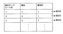
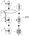
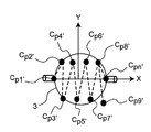
- FIG. 25A is a diagram for explaining a list of operation template information in the third embodiment of the present invention
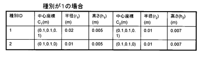
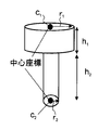
- FIG. 25B is a tabular view showing the center coordinates and radius of the action template when the action template ID in the table of FIG. 25A is “1” and the type is 1.
- FIG. 25C is a tabular diagram showing the center coordinates and radius of the action template when the action template ID in the table of FIG. 25A is “2” and the type is 2.
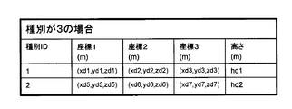
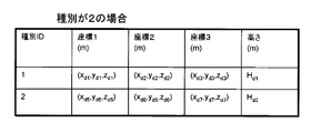
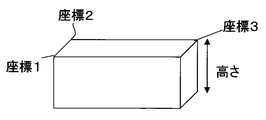
- FIG. 25D is a table format diagram showing coordinates 1 to 4 of the action template when the action template ID in the table of FIG. 25A is “3” and the type is 3.
- FIG. 25E is the operation template information of FIG.
- FIG. 25D is a diagram for explaining the operation in which the hand of the robot arm moves zigzag and stirs in the pan.
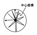
- FIG. 25F is the operation template information of FIG. 25B, and is a diagram for explaining the operation of moving the hand of the robot arm so as to draw a circle and stirring the pot.
- FIG. 25G is the operation template information of FIG. 25C, and is a diagram for explaining the operation in which the hand of the robot arm moves radially and stirs in the pan.
- FIG. 26A is a diagram illustrating an operation of stirring the pot at the hand of the robot arm in the operation template information in the third embodiment of the present invention.
- FIG. 26B is a diagram for explaining the operation of stirring the pot at the hand of the robot arm in the operation template information in the third embodiment of the present invention
- FIG. 26C is a diagram illustrating an operation of stirring the pot at the hand of the robot arm in the operation template information in the third embodiment of the present invention
- FIG. 27 is a diagram illustrating flag information of the operation information database in the third embodiment of the present invention.
- FIG. 28A is a diagram illustrating a list of environment information in the environment information database according to the third embodiment of the present invention.
- FIG. 28B is an explanatory diagram for explaining the environment information of the environment information database in a table format according to the third embodiment of the present invention.
- FIG. 28C is an explanatory diagram for explaining the environment information in the environment information database in a table format according to the third embodiment of the present invention.
- FIG. 28D is an explanatory diagram for explaining the environment information in the environment information database in the third embodiment of the present invention in a table format;
- FIG. 28E is an explanatory diagram illustrating information about an object of environment information in the environment information database according to the third embodiment of the present invention.
- FIG. 28F is an explanatory diagram illustrating information related to a circle of environment information in the environment information database according to the third embodiment of the present invention.
- FIG. 28G is an explanatory diagram illustrating information related to a rectangular parallelepiped of environment information in the environment information database according to the third embodiment of the present invention.
- FIG. 29 is a diagram illustrating a list of correction parameters in a correction parameter database according to the third embodiment of the present invention.
- FIG. 30 is a diagram for explaining information on correction parameter flags in the third embodiment of the present invention.
- FIG. 31A is an explanatory diagram showing a control operation state of a robot arm and an operation state by a human by the robot arm control device according to the third embodiment of the present invention;
- FIG. 31B is an explanatory diagram showing a control operation state of the robot arm by the robot arm control device according to the third embodiment of the present invention;
- FIG. 31C is an explanatory diagram showing a control operation state of the robot arm by the robot arm control device according to the third embodiment of the present invention;
- FIG. 31A is an explanatory diagram showing a control operation state of a robot arm and an operation state by a human by the robot arm control device according to the third embodiment of the present invention;
- FIG. 31B is an explanatory diagram showing a control operation state of the robot arm by the robot arm control
- FIG. 31D is a plan view for explaining a control operation state of the robot arm by the robot arm control device according to the third embodiment of the present invention
- FIG. 32 shows an operation correction unit, an information generation unit, an operation selection unit, a correction method setting unit, an operation storage unit, an operation information database, an environment information database, and a correction parameter database of the robot arm control device according to the third embodiment of the present invention.
- FIGS. 33 (a) to 33 (g) are explanatory views showing the control operation state of the robot arm and the operation state by a human by the control device for the robot arm in the fourth embodiment of the present invention, FIG.
- FIG. 34 is a diagram illustrating a list of operation information in the operation information database of the robot arm control device according to the fourth embodiment of the present invention.
- FIG. 35A is an explanatory diagram illustrating an operation state of the robot arm control device according to the fourth embodiment of the present invention.
- FIG. 35B is a plan view showing an operation state of the control device for the robot arm in the fourth embodiment of the present invention;
- FIG. 35C is a plan view showing an operation state of the robot arm control device according to the fourth embodiment of the present invention;
- FIG. 35D is a plan view showing an operation state of the control device for the robot arm according to the fourth embodiment of the present invention;
- FIG. 35E is a plan view showing an operation state of the robot arm control apparatus according to the fourth embodiment of the present invention;
- FIG. 35A is an explanatory diagram illustrating an operation state of the robot arm control device according to the fourth embodiment of the present invention.
- FIG. 35B is a plan view showing an operation state of the control device for the robot arm in the
- FIG. 36 is a diagram illustrating a detailed configuration of a robot arm control device and a robot arm that is a control target that configure a robot system according to a fifth embodiment of the present invention
- FIG. 37 is a diagram illustrating a list of operation information in the operation information database of the robot system and cooking appliance information in the cooking appliance information database according to the fifth embodiment of the present invention.
- FIG. 38A is a diagram showing the relationship between the force applied by a person and the time in the sixth embodiment of the present invention
- FIG. 38B is a diagram showing a relationship between the force applied by a person and the time in the sixth embodiment of the present invention
- FIG. 39 is a diagram for explaining a list of information set in the correction method setting unit in the sixth embodiment of the present invention.
- FIG. 38A is a diagram showing the relationship between the force applied by a person and the time in the sixth embodiment of the present invention
- FIG. 38B is a diagram showing a relationship between the force applied by a person and the time in the sixth embodiment of the present
- FIG. 40 is a diagram showing an outline of a configuration of a robot arm control device and a robot arm that is a control target that constitute a robot system according to a seventh embodiment of the present invention
- FIG. 41 is a diagram illustrating a detailed configuration of a robot arm control device and a robot arm that is a control target that configure a robot system according to a seventh embodiment of the present invention
- FIG. 42 is an explanatory diagram in the form of a list of operation information in the operation information database.
- FIG. 43A is a diagram illustrating a list of environment information in the environment information database according to the seventh embodiment of the present invention.
- FIG. 43B is a diagram illustrating a list of environment information in the environment information database according to the seventh embodiment of the present invention.
- FIG. 43A is a diagram illustrating a list of environment information in the environment information database according to the seventh embodiment of the present invention.
- FIG. 43B is a diagram illustrating a list of environment information in the environment information database according to the seventh embodiment of the present
- FIG. 43C is a diagram showing an object represented by the environment information in the environment information database of FIG. 43B in the seventh embodiment of the present invention
- FIG. 43D is a diagram illustrating a list of environment information in the environment information database according to the seventh embodiment of the present invention
- FIG. 43E is a diagram showing an object represented by the environment information in the environment information database of FIG. 43D in the seventh embodiment of the present invention
- FIG. 43F is a diagram illustrating a list of environment information in the environment information database according to the seventh embodiment of the present invention
- FIG. 43G is a diagram showing a circle represented by the environment information in the environment information database of FIG. 43F in the seventh embodiment of the present invention.
- a control device for a robot arm that controls the operation of the robot arm
- the motion information is acquired from a motion information database in which at least one of the position, posture, and speed of the robot arm corresponding to the motion is stored as motion information in time series, and a person
- a position control unit for controlling the robot arm to move based on the motion information An operation correction unit that corrects the operation information according to the correction operation information at each time acquired by the information acquisition unit while the robot arm is moving while being controlled by the position control unit.
- a robot arm control device that controls the movement of the robot arm based on the movement information corrected by the movement correction unit.
- the operation information can be corrected according to human power.
- a control device for a robot arm that controls the operation of the robot arm,
- the robot arm obtains the motion information from the motion information database stored as time-series motion information of the force applied to the object by the robot arm corresponding to the motion, and a person operates the robot arm to
- An information acquisition unit for acquiring correction operation information related to the force applied by the robot arm when correcting the operation of A force control unit that controls the object while pressing it with the force of the motion information;
- an operation correction unit that corrects the operation information according to the correction operation information at each time acquired by the information acquisition unit,
- a robot arm control device for controlling the movement of the robot arm based on the movement information corrected by the movement correction unit.
- the information processing unit further includes a force detection unit that detects the force of the person applied to the robot arm, and the information acquisition unit detects the force of the person detected by the force detection unit.
- the correction operation information is acquired according to the above, and the robot arm control device according to the first or second aspect is provided.
- the motion information acquired by the information acquisition unit includes geometric motion template information for generating the motion of the robot arm, An environment information acquisition unit for acquiring environment information related to an environment in which the robot arm operates; A motion information expansion unit that generates the motion information of the robot arm from the motion template information included in the motion information based on the environment information; Further, the information acquisition unit may acquire each time acquired by the information acquisition unit while the robot arm is moving while being controlled by the position control unit with the operation information expanded by the operation information expansion unit.
- the template information of the operation is corrected in accordance with the corrected operation information in the operation, and the template information corrected by the operation correction unit is based on the operation information generated by the operation information expansion unit.
- the robot arm control device according to the first or third aspect is characterized by controlling the operation of the robot arm.
- the operation information can be corrected based on environment information, and further, the operation information in the operation information database can be corrected according to the human power.
- the robot arm control device further comprising a correction method setting unit for setting a method of correcting the motion information by the motion correction unit,
- a correction method setting unit for setting a method of correcting the motion information by the motion correction unit
- the operation method can be set.
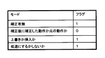
- the correction method setting unit sets correction information indicating whether or not to correct the operation information
- the operation correction unit refers to the correction presence / absence information set by the correction method setting unit and indicates that the correction information of the operation information is corrected
- the operation correction unit performs the operation.
- the robot arm according to the fifth aspect wherein the operation information is not corrected when the information on correction is not corrected while the correction information setting unit sets the correction method.
- a control apparatus is provided.
- the correction method setting unit corrects the correction when the human force detected by the force detection unit becomes smaller than a threshold value after correction by the operation correction unit.
- Set the correction method of whether to return to the operation before the correction, or the operation correction unit is set by the correction method setting unit, referring to the correction method, If the human force detected by the force detection unit becomes smaller than a threshold value after correction by the operation correction unit, whether to operate with the corrected operation or to return to the operation before the correction Switch Based on the motion information corrected by the motion correction unit, after controlling the motion of the robot arm and correcting by the motion correction unit, the human force detected by the force detection unit is greater than a threshold value.
- the robot arm control device according to the fifth aspect, wherein the operation of the robot arm is controlled by the operation switched by the correction method set by the correction method setting unit when the value becomes smaller.
- the correction method setting unit when the correction method setting unit is set to correct the operation information, and after the correction by the operation correction unit is set to not correct the operation information, Set the correction method to operate in the corrected operation or return to the operation before the correction, the operation correction unit with reference to the correction method set in the correction method setting unit, When the operation information is set to be corrected and the operation correction unit is set to correct the operation information and then the operation information is set not to be corrected, the operation is performed with the corrected operation or the operation before the correction is restored.
- Switch or The correction method when the operation information is set not to be corrected after the operation of the robot arm is controlled and corrected by the operation correction unit based on the operation information corrected by the operation correction unit.
- a robot arm control device according to a sixth aspect, wherein the operation of the robot arm is controlled by an operation switched by the correction method set by a setting unit.
- the operation information is set to be corrected and the operation correction unit is set to correct the operation information, the operation information is set to be corrected. It is possible to switch back to the operation before applying human power.
- the correction method setting unit operates by overwriting the operation after correction by the operation correction unit over the operation before correction or by inserting it.
- the operation correction unit refers to the correction method set by the correction method setting unit, and the operation after the correction by the operation correction unit is overwritten on the operation before correction or is inserted.
- Switch the operation Based on the motion information corrected by the motion correction unit, the motion of the robot arm is controlled and corrected by the motion correction unit, and then switched by the correction method set by the correction method setting unit.
- the robot arm control device according to the fifth aspect, wherein the operation of the robot arm is controlled by the operation performed.
- the correction method setting unit can switch between the operation after correction by the operation correction unit over the operation before correction or the operation after insertion. .
- the robot arm control device corrects the operation so as to be slower or stopped than the portion of the above.
- the correction method setting unit when the correction method setting unit switches to an operation in which a person directly grips the robot arm and operates the robot arm to perform the correction, the correction method setting unit determines the speed of the operation before the switching. Set the correction method for whether or not to operate at low speed, The operation correction unit refers to the correction method set by the correction method setting unit. When a person directly grips the robot arm and operates the robot arm, the speed of the robot arm is controlled before the operation.
- the correction method setting unit The robot arm control device according to a fifth aspect, wherein the operation of the robot arm is controlled by the operation switched by the correction method set in (5).
- the correction method setting unit can switch whether or not to change the speed of the motion information according to the human power.
- the apparatus further includes a correction parameter type acquisition unit that acquires a type of a parameter to be corrected. At least one of the position, posture, and speed of the robot arm is determined for each direction.
- the motion correction unit refers to the type of the parameter to be corrected acquired by the correction parameter acquisition unit.
- a robot arm control device according to a first aspect of correcting only the determined correction parameter is provided.
- the apparatus further includes a correction parameter type acquisition unit that acquires a type of parameter to be corrected, and the type of parameter to be corrected is the position of the operation information when the operation information is corrected. And at least one type of posture and speed is determined by direction, When the motion correction unit corrects the motion information in the motion information database, the motion correction unit refers to the type of the parameter to be corrected acquired by the correction parameter acquisition unit.
- a robot arm control device according to a first aspect of correcting only the determined correction parameter is provided.
- the apparatus further includes a correction parameter type acquisition unit that acquires a type of a parameter to be corrected, and the type of the parameter to be corrected is the value of the operation information when the operation information is corrected.
- the type of information about force is determined by direction
- the motion correction unit refers to the type of the parameter to be corrected acquired by the correction parameter acquisition unit.
- the robot arm control device according to the second aspect, wherein only the determined correction parameter is corrected.
- the apparatus further includes a correction parameter type acquisition unit that acquires a type of a parameter to be corrected, and the type of the parameter to be corrected is the value of the operation information when the operation information is corrected. It determines the type of each parameter that makes up the template information of the action, When the motion correction unit corrects the motion information in the motion information database, the motion correction unit refers to the type of the parameter to be corrected acquired by the correction parameter acquisition unit.
- a correction parameter type acquisition unit that acquires a type of a parameter to be corrected, and the type of the parameter to be corrected is the value of the operation information when the operation information is corrected. It determines the type of each parameter that makes up the template information of the action.
- the motion correction unit refers to the type of the parameter to be corrected acquired by the correction parameter acquisition unit.
- the robot arm control device according to the fourth aspect, wherein only the determined correction parameter is corrected.
- the motion correction unit restrains the motion of the robot arm according to the force of the person detected by the force detection unit according to the type of the correction parameter.
- the robot arm control device according to any one of the thirteenth to fifteenth aspects is provided, which corrects the motion information in the motion information database.
- any one of the thirteenth to fifteenth aspects further comprising an information generation unit that creates the operation information in association with the type of the correction parameter.
- an information generation unit that creates the operation information in association with the type of the correction parameter.
- the operation information and the type of the correction parameter can be created in association with each other.
- the robot arm according to any one of the thirteenth to fifteenth aspects, wherein the robot arm has a display unit that displays the correction parameter when the operation correction unit corrects the operation.
- a control device is provided.
- the correction parameter can be displayed.
- the high-rigidity position control mode prevents the robot arm from moving and touching by a human operation.
- a control device for a robot arm which corrects force information.
- the motion information in the motion information database is corrected with low-rigidity position control according to the force of the person during operation with position control and impedance control. can do.
- the motion correction unit may be configured to correct the motion information while the robot arm is moving while being controlled by the position control unit.
- the control device for the robot arm according to the first or fourth aspect is provided, wherein the correction is performed by switching to a control mode in which the movement is performed by the operation.
- the motion correction unit corrects the motion information in the motion information database by impedance control according to the force of the person during the motion by position control based on the information in the motion information database. can do.
- a twenty-first aspect of the present invention further comprising an operation storage unit that stores the operation corrected by the operation correction unit,
- the robot arm control device according to any one of the first to fourth aspects, wherein the storage start time of the motion storage unit starts after a certain time has elapsed since the correction was started. provide.
- the storage start time of the operation storage unit can be started after a certain time has elapsed since the correction was started.
- the apparatus further includes an operation storage unit that stores the operation corrected by the operation correction unit, The control of the robot arm according to the third aspect, wherein the storage start time of the motion storage unit starts when the human power detected by the force detection unit exceeds a certain threshold value. Providing equipment.
- the storage start time of the motion storage unit can be determined according to the human power.
- the motion information acquisition unit acquires a plurality of the motion information, From the plurality of movement information acquired by the movement information acquisition unit, further comprising a movement selection unit that selects movement information according to the force of the person detected by the force detection unit, The motion correction unit corrects the motion information selected by the motion selection unit, and provides the robot arm control device according to the third aspect.
- the correction method setting unit determines whether to switch the motion information to be corrected or not according to a human force detected by the force detection unit.
- a robot arm control device according to the third aspect is provided.
- another peripheral device existing around the robot arm, a peripheral device information acquisition unit that acquires peripheral device information that is information related to the peripheral device, and the operation correction unit Provides the robot arm control device according to the first or second aspect, wherein the peripheral device is controlled when the motion information is corrected.
- peripheral devices can be controlled during the correction of the operation information.
- a robot arm control method for controlling an operation of a robot arm
- the information acquisition unit acquires the information from the operation information database in which at least one of the position, posture, and speed of the robot arm corresponding to the operation is stored as operation information in time series.
- the information acquisition unit acquires at least one correction operation information of the position, posture and speed of the robot arm when correcting the operation of the robot arm, Controlling the robot arm with a position controller to move based on the motion information; While the robot arm is moving while being controlled by the position control unit, the operation information is corrected by the operation correction unit according to the correction operation information at each time acquired by the information acquisition unit, A robot arm control method is provided that controls the movement of the robot arm based on the movement information corrected by the movement correction unit.
- the robot arm control method stores operation information, which is information related to the operation of the robot arm, detects a human force, and corrects the operation information according to the human force.
- operation information which is information related to the operation of the robot arm.
- the robot arm comprising the robot arm control device according to any one of the first to 25th aspects for controlling the robot arm.
- a robot arm control program for controlling the operation of the robot arm
- the information acquisition unit acquires the information from the operation information database in which at least one of the position, posture, and speed of the robot arm corresponding to the operation is stored as operation information in time series.
- the information acquisition unit acquires at least one correction operation information of the position, posture and speed of the robot arm when correcting the operation of the robot arm, Controlling the robot arm with a position controller to move based on the motion information; While the robot arm is moving while being controlled by the position control unit, the operation correction unit corrects the operation information according to the correction operation information at each time acquired by the information acquisition unit.
- a robot arm control program for executing a step of controlling the movement of the robot arm based on the movement information corrected by the movement correction unit is provided.
- the method includes a step of correcting the motion information in the motion information database using a motion information database in which information on the motion of the robot arm is stored and according to the detected human power.
- a robot arm control program can be provided.
- an integrated electronic circuit for controlling the operation of the robot arm The motion information is acquired from a motion information database in which at least one of the position, posture, and speed of the robot arm corresponding to the motion is stored as motion information in time series, and a person To obtain at least one correction operation information of the position, posture and speed of the robot arm when correcting the operation of the robot arm, A position control unit for controlling the robot arm to move based on the motion information; An operation correction unit that corrects the operation information according to the correction operation information at each time acquired by the information acquisition unit while the robot arm is moving while being controlled by the position control unit. And An integrated electronic circuit for controlling a robot arm is provided, wherein the operation of the robot arm is controlled based on the motion information corrected by the motion correction unit.
- an operation information database in which information related to the operation of the robot arm is stored, and an operation correction unit that corrects the operation information in the operation information database according to the human force detected by the force detection unit. It is possible to provide an integrated electronic circuit for controlling a robot arm.
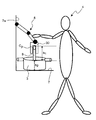
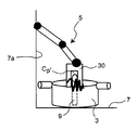
- FIG. 1 is a diagram showing an outline of a robot system 1 including a robot arm 5 and its control device 70 in the first embodiment of the present invention.
- the robot arm 5 of the robot system 1 is installed on a wall surface 7a of a work table 7 such as a kitchen or a table in the home, and the base end of the robot arm 5 is fixed to the wall surface 7a.
- the robot 8 is movably supported on the rail 8, and the robot arm 5 is movable on the rail 8 in the lateral direction along the rail 8, for example, in the horizontal direction by the force of the person 4.
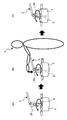
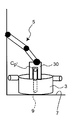
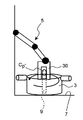
- the robot system 1 is a work performed in cooperation with the robot arm 5 and the person 4 in the home, for example, a work of stirring the ingredients in the pot 3 using the robot arm 5 or a robot arm.
- 5 is a robot system that uses 5 to wipe the kitchen dirt.
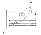
- An example of the operation procedure of the robot system 1 such as a stirring operation in the pot 3 by the robot system 1 or a wiping and cleaning operation of the top plate of the IH cooking heater by the robot system 1 is shown in FIG.
- the person 4 directly grips or pushes the robot arm 5 of the robot system 1, the person 4 applies force to the robot arm 5. Then, the robot arm 5 of the robot system 1 is moved along the rail 8 by the force applied from the person 4 to the robot arm 5, thereby guiding the robot arm 5 to the vicinity of the instrument 3.
- the person 4 applies a tool 9 such as a ladle for stirring work or a tool 46 for wiping work to the hand 30 of the robot arm 5 of the robot system 1, that is, the tip hand 30 (see FIG. 14A of the second embodiment). ).
- a tool 9 such as a ladle for stirring work or a tool 46 for wiping work to the hand 30 of the robot arm 5 of the robot system 1, that is, the tip hand 30 (see FIG. 14A of the second embodiment).
- the robot The arm 5 is actuated to start a preselected operation, that is, a stirring operation or a wiping operation.
- a preselected operation that is, a stirring operation or a wiping operation.
- the person 4 confirms the state of the ingredients in the pot 3, and the person 4 applies force to the robot arm 5.
- the operation storing unit 15 uses the information stored in the operation information database 17 to select an optimal mixing method, which will be described later, and a display unit described later
- the person 4 directly applies force to the robot arm 5 in the direction to be corrected by directly gripping or pushing the robot arm 5 of the robot system 1, and the operation of the robot arm 5 of the robot system 1. Correct.
- the rail 8 is arranged on the wall surface 7a of the work table 7.
- it can be installed at a place suitable for work such as a ceiling surface or a side surface of the island kitchen top plate.
- operation panel 13 is fixed to the side surface of the cooking device 6, a remote control capable of remote operation may be used instead of the operation panel 13.
- FIG. 2 is a diagram showing a detailed configuration of the robot arm 5 to be controlled and the control device 70 of the robot arm 5 that constitute the robot system 1.
- the control device 70 of the robot arm 5 includes a control device main body 11, a motion generation device 12 that generates motion of the robot arm 5, and a peripheral device 14, as shown in detail in FIG. 2.
- the control device main body 11, the motion generation device 12, and the peripheral device 14 are each configured by a general personal computer as an example.
- the control device main body 11 is configured to have a control parameter management unit 21 and a control unit 22. Between the control unit 22 and the control parameter management unit 21, information on the hand position and force of the robot arm 5 is input / output.
- the motion generation device 12 is configured to include a motion information database 17, a motion selection unit 27, a motion correction unit 20, a correction method setting unit 23, and a motion storage unit 15. Between the motion correction unit 20 and the control parameter management unit 21, hand position and posture of the robot arm 5, information on the force applied by the person 4, an operation command and the like are input and output, and the control parameter management unit 21. From the hand position and posture of the robot arm 5 and information on the force applied by the person 4, etc. are output to the action storage unit 15, and the hand position and posture of the robot arm 5 and the person 4 are added. The force information and the like are output to the operation selection unit 27.
- the 2A has a function of acquiring the operation information selected by the operation selection unit 27 from the operation information database 17 as described later, but is not limited thereto. This function may be provided as the first information acquisition unit 101 independently of the operation correction unit 20.
- the control parameter management unit 21 shown in FIG. 2A has a function of acquiring operation information such as the hand position and posture of the robot arm 5 and information on the force applied by the person 4 as will be described later.
- the present invention is not limited to this, and this function may be provided as the second information acquisition unit 102 independently of the control parameter management unit 21. In this case, in addition to the case where the first information acquisition unit 101 and the second information acquisition unit 102 are provided separately, as shown in FIG.
- the first information acquisition unit 101 and the second information acquisition unit 100 are included in one information acquisition unit 100.
- the information acquisition unit 102 may be included.
- FIG. 2B only the part having the information acquisition function is different from FIG. 2A, and the function itself is the same. Therefore, the following description will be made based on FIG. 2A as a representative example.
- the peripheral device 14 is configured to have a data input IF (interface) 26, an input / output IF (interface) 24, a motor driver 25, and the display unit 2.
- Control information such as a control signal is output from the control unit 22 to the input / output IF 24.
- correction information such as correction parameters stored in the motion information database 17 and a video or photograph or text corresponding to the motion ID are output to the display unit 2, and the robot arm 5 described by the motion information is described.
- the video, photograph or text of the operation is displayed on the display unit 2.
- the input / output IF 24 is configured to have, for example, a D / A board, an A / D board, a counter board, and the like connected to an expansion slot such as a PCI bus of a personal computer.
- the input / output IF 24 receives each joint angle information output from an encoder 44 described later and angle information output from the encoder 61 of the hand 30 of each joint portion of the robot arm 5 and inputs it to the control unit 22.
- Control information such as a control signal is input from the control unit 22 to the input / output IF 24, and control information such as a control command value is output to the motor driver 25.
- the motor driver 25 outputs control information such as control command values to the motor 43 described later and the motor 62 of the hand 30 of each joint portion of the robot arm 5.
- the operations of the motion generation device 12, the control device main body 11, and the peripheral device 14 are executed, and output from encoders 44 described later of each joint portion of the robot arm 5.
- the respective joint angle information is taken into the control device main body 11 through the counter board of the input / output IF 24, and the control command value in the rotation operation of each joint by the control device main body 11 based on the taken joint angle information. Is calculated.
- the calculated control command values are given to the motor driver 25 for driving and controlling the joints of the robot arm 5 through the D / A board of the input / output IF 24, and the control command values sent from the motor driver 25 are sent. Accordingly, the motor 43 of each joint portion of the robot arm 5 is driven.
- a hand drive motor 62 and an encoder 61 that detects the rotation phase angle of the rotation shaft of the hand drive motor 62 are further provided in the hand 30.
- the rotation angle information detected by the encoder 61 is taken into the control device main body 11 through the counter board of the input / output IF 24, and the control unit 22 of the control device main body 11 is based on the taken rotation angle information.
- a control command value for the opening / closing operation of the hand 30 is calculated by the hand control unit 54 (shown in FIG. 12).
- the calculated control command value is given to the motor driver 25 that also opens and closes the hand 30 through the D / A board of the input / output IF 24, and the motor 62 is rotated according to each control command value sent from the motor driver 25.
- the hand 30 is opened and closed by controlling the drive and rotating the rotating shaft of the motor 62 for driving the hand forward and backward.
- the robot arm 5 is an articulated robot arm, which is a multi-link manipulator with 6 degrees of freedom, and includes the hand 30 and a forearm link 32 having a wrist 31 to which the hand 30 is attached at the tip, An upper arm link 33 whose front end is rotatably connected to the base end of the forearm link 32 and a base portion 34 on which the base end of the upper arm link 33 is rotatably connected and supported are provided.
- the base part 34 is connected to the rail 8 so as to be movable, it may be fixed at a fixed position.
- the wrist portion 31 has three rotation axes of the fourth joint portion 38, the fifth joint portion 39, and the sixth joint portion 40, and the relative posture (direction) of the hand 30 with respect to the forearm link 32. Can be changed. That is, in FIG. 2A, the fourth joint portion 38 can change the relative posture around the horizontal axis of the hand 30 with respect to the wrist portion 31.
- the fifth joint portion 39 can change the relative posture of the hand 30 with respect to the wrist portion 31 around the vertical axis perpendicular to the horizontal axis of the fourth joint portion 38.
- the sixth joint portion 40 can change the relative posture of the hand 30 with respect to the wrist portion 31 about the horizontal axis orthogonal to the horizontal axis of the fourth joint portion 38 and the vertical axis of the fifth joint portion 39.
- the other end of the forearm link 32 is rotatable around the third joint portion 37 with respect to the tip of the upper arm link 33, that is, around a horizontal axis parallel to the horizontal axis of the fourth joint portion 38.
- the other end of the upper arm link 33 is rotatable around the second joint portion 36 with respect to the base portion 34, that is, around a horizontal axis parallel to the horizontal axis of the fourth joint portion 38.
- the upper movable portion 34a of the pedestal 34 rotates around the first joint 35 relative to the lower fixed portion 34b of the pedestal 34, that is, around the vertical axis parallel to the vertical axis of the fifth joint 39. It is possible.
- the robot arm 5 constitutes the multi-link manipulator having 6 degrees of freedom so as to be rotatable around a total of six axes.
- each joint portion constituting the rotation portion of each axis there is a rotation drive device such as a motor 43 and an encoder 44 (actually, a robot arm) that detects a rotation phase angle (that is, a joint angle) of the rotation axis of the motor 43. 5 is provided in each joint part).
- the motor 43 (actually disposed inside each joint portion of the robot arm 5) supports a pair of members (for example, a rotation side member and the rotation side member) constituting each joint portion. Of the support side member) is driven and controlled by a motor driver 25 described later.
- the rotation shaft of the motor 43 provided in one member of each joint portion is connected to the other member of each joint portion, and rotates the rotation shaft forward and backward, whereby the other member is moved with respect to the one member. Can be rotated around each axis.
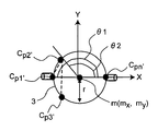
- Reference numeral 41 denotes an absolute coordinate system in which the relative positional relationship is fixed with respect to the lower fixed portion 34 b of the base portion 34
- reference numeral 42 denotes a hand coordinate system in which the relative positional relationship with respect to the hand 30 is fixed.
- the origin position O e (x, y, z) of the hand coordinate system 42 viewed from the absolute coordinate system 41 is the hand position of the robot arm 5, and the posture of the hand coordinate system 42 viewed from the absolute coordinate system 41 is the roll angle and the pitch angle.
- the horizontal axis of the sixth joint portion 40 can be positioned parallel to the x axis of the hand coordinate system 42
- the horizontal axis of the fourth joint portion 38 can be positioned parallel to the y axis
- z It is preferable that the vertical axis of the fifth joint portion 39 can be positioned parallel to the axis.
- the rotation angle of the hand coordinate system 42 with respect to the x-axis is the yaw angle ⁇
- the rotation angle with respect to the y-axis is the pitch angle ⁇
- the rotation angle with respect to the z-axis is the roll angle ⁇ .
- Reference numeral 26 denotes a data input IF (interface), which is a correction for the person 4 to input or change operation information or a parameter type to be corrected, which will be described later, using an input device such as a keyboard or a mouse or a microphone. This is an interface for inputting method setting information to the correction method setting unit 23. Further, the data input IF 26 may receive an instruction to start and end the control operation from the person 4 to the correction method setting unit 23 using an input device such as the button 13a of the operation panel 13 of FIG. . As the button 13a, for example, it is possible to input a control operation start and a control operation end with one button as a toggle switch, or a control operation start button and a control operation end button may be provided separately.
- a display unit for example, a display device installed on the side surface of the robot arm 5 or the workbench 7 and displays operation information described later or the type of parameter to be corrected.
- the operation information database 17 inputs / outputs operation information to / from the operation selection unit 27, inputs / outputs operation information to / from the operation correction unit 20, and the operation storage unit 15 stores various operation information. Input and memorize.
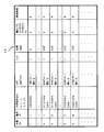
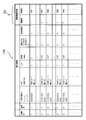
- the operation information database 17 for example, information related to the operation of the robot arm 5 shown in FIG.
- information related to the operation a work ID number for identifying a work (see the column of “work ID” in FIG. 3) and an operation ID number for identifying individual actions in the work (in FIG. 3).
- the parameters of the hand position and posture of the robot arm 5 see the column “Operation ID”
- information on the hand position and posture of the robot arm 5 in that motion see the column “Position and posture” in FIG. 3
- Information relating to a flag indicating which information is valid see the “flag” column in FIG. 3) and information indicating whether the hand 30 is open or closed (see the “hand” column in FIG.
- Information relating to the time during which each action acts (see the “time” column in FIG. 3), and the type of parameter to be corrected when the action correction unit 20 described later corrects action information in the action information database 17.
- information( 3) (see the column “Correction Parameters” in FIG. 3), and progress information (see the “Progress Information” column in FIG. 3) indicating whether or not the operation of the robot arm 5 selected by the action selection unit 27 described later is currently being executed. It is comprised so that it may contain.
- the work ID is a code used to identify information related to the work
- the action ID is a code used to identify information related to the action.
- the information related to the “flag” in the motion information database 17 in FIG. 3 is a value indicating which information of the hand position and posture of the robot arm 5 based on the motion information indicated by each “motion ID” is valid. Specifically, it is represented by the 32-bit numerical value shown in FIG. In FIG. 4, “1” is set when each value of the hand position and posture is valid, and “0” is set when each value of the hand position and posture is invalid. For example, in the 0th bit, “1” is set when the x coordinate value of the hand position of the robot arm 5 is valid, and “0” is set when the x coordinate value of the hand position is invalid.
- the robot arm 5 When the z-coordinate value of the hand position is valid, “1” is set, and when the z-coordinate value of the hand position is invalid, “0” is set.
- the orientation ⁇ Each represents the validity of ⁇ and ⁇ (that is, “1” when valid and “0” when invalid).
- the 7th to 31st bits are not used, so “0” is inserted.
- the flag may be a variable that can store only 6 bits.
- the 0th bit to the 2nd bit are “1”, it indicates that only x, y, z information is valid among the operation information, and the 3rd to 5th bits are “ Therefore, it is assumed that any value stored in the values of ⁇ , ⁇ , and ⁇ in the operation information is invalid.
- the information regarding “hand” indicating whether or not the hand 30 is opened / closed in the operation information database 17 of FIG. 3 is a flag indicating whether the hand 30 is open / closed while the robot arm 5 is operating. Is described as “0”, and “1” is described when the hand 30 is closed.
- the information related to “time” in the motion information database 17 in FIG. 3 is the time for executing each motion of the robot arm 5, and the motion stored in this “motion ID” is the information related to “time” here. It represents performing over time stored as. That is, it represents the relative time from the previous operation, not the absolute time. That is, it represents the time until the hand 30 of the robot arm 5 moves to the position and posture indicated by the “operation ID”.
- FIG. 3 is information indicating which parameter is corrected by the operation correction unit 20 to be described later. Specifically, it is represented by a 32-bit numerical value shown in FIG. In FIG. 5, “1” is set when each value of the hand position and posture can be corrected by each bit, and “0” is set when the values of the hand position and posture cannot be corrected. .
- “1” is set when the x-coordinate value of the hand position can be corrected
- “0” is set when the x-coordinate value of the hand position cannot be corrected.
- “1” is set.
- the y-coordinate value of the hand position cannot be corrected “0” is set.
- the hand position is set. If the z-coordinate value can be corrected, it is set to “1”. If the z-coordinate value of the hand position cannot be corrected, it is set to “0”. , ⁇ , and ⁇ respectively represent correction possibilities (that is, “1” when correction is possible and “0” when correction is impossible).
- the correction parameter flag is valid only for the parameter for which the “flag” in the operation information database 17 is valid, and “1” is set in the correction parameter flag for the parameter for which “flag” is invalid, that is, “0” is set. If it is, “0” is assumed to be set.
- the correction parameter flag is prepared in a large number (32 bits) for future expansion, in this example, since the 7th to 31st bits are not used, “0” is set. It is good also as a variable which can store only a bit.
- “Progress information” is an information flag indicating whether or not the robot arm 5 is currently being operated. If the operation is being executed, “1” is set. If the operation is not being executed, “0” is set.
- the motion information is stored in the motion information database 17 by the motion storage unit 15. Specifically, the person 4 causes the robot arm 5 to perform the operation of the robot arm 5 to be selected, and the operation selection unit 27 performs work on the basis of the information stored in the operation information database 17 by the operation storage unit 15. Select the work you want to do. Then, when the selected work is started, “1” is stored in the motion information database 17 by the motion storage unit 15 for the currently running motion among the motions of the task, and “0” is set for the motion that is not working. Is stored in the operation information database 17 by the operation storage unit 15.
- Reference numeral 27 in FIG. 2A denotes an operation selection unit, which is based on the position of the hand of the robot arm 5 when a person applies force to the robot arm 5 and the time at that time, among the operations stored in the operation control database 17.
- the operation to be performed by the robot arm 5 is selected from the operations in the operation control database 17.
- the motion selection unit 27 receives, from the control parameter management unit 21, the hand position and posture of the robot arm 5, information on the force applied by the person 4, etc. Information on the hand position and posture of the robot arm 5 is input / output.
- a work including the selected action is selected from the work list of the action information database 17 by the action selecting unit 27, and among the selected works, the “action ID” related to the currently executed action “ “1” is set in the “progress information” by the operation selection unit 27, and “0” is set by the operation selection unit 27 for “operation ID” of other operations.
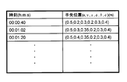
- the movement that the person 4 wants to operate is executed by directly grasping the robot arm 5 and operating the robot arm 5, and at that time, as shown in FIG.
- the hand position of the robot arm 5 when the force is applied and the time at that time are associated with each other and stored in the motion information database 17 by the motion storage unit 15.
- the information on the hand position and posture of the robot arm 5 that is stored in advance in the motion information database 17 and related to the motions of all the robot arms 5, and the motion information database as shown in FIG. 17, the information on the hand position and posture of the robot arm 5 is compared with each other in time series by the motion selection unit 27, and the information on the hand position and posture of the robot arm 5 when the person 4 applies force is If the difference between the robot arm 5 pre-stored in the information database 17 and the information on the hand position and posture of the robot arm 5 relating to a certain movement is within a predetermined error range, the movement is determined to match.
- the operation selecting unit 2 determines that the operation that is determined by the selection unit 27 and is determined to be the same as the operation that the person 4 wants the robot arm 5 to operate.
- the action selection unit 27 selects a default work (for example, a work whose “work ID” number is “1”). All the operations of the work of “work ID” selected by the motion selection unit 27 are executed in order from the smallest “motion ID” number, and when the operation is executed up to the last operation, Returning to the operation of “operation ID” at the head of “ID”, a series of operations are repeatedly executed.
- a default work for example, a work whose “work ID” number is “1”. All the operations of the work of “work ID” selected by the motion selection unit 27 are executed in order from the smallest “motion ID” number, and when the operation is executed up to the last operation, Returning to the operation of “operation ID” at the head of “ID”, a series of operations are repeatedly executed.
- the person 4 holds the robot arm 5 directly, and the person 4 holds the robot arm 5 in the impedance control mode to be described later.
- information on the hand position and posture of the robot arm 5 is acquired at certain time intervals (for example, every 0.2 msec), and is stored in the operation information database 17 by the operation storage unit 15 along with the time. To make it.
- correction method setting unit 23 is a correction method setting unit, which sets a method of correcting operation information of the robot arm 5 by the operation correction unit 20 described later.
- Correction method setting information is input to the correction method setting unit 23 from the data input IF 26, and information on whether correction is present (for example, a flag indicating whether correction is present) between the operation correction unit 20 and the correction method setting unit 23. Input or output.
- the operation correction unit 20 outputs correction information related to operation information such as correction parameters to the display unit 2. Specifically, when the force of the person 4 is applied to the robot arm 5, information on whether or not to correct the operation of the robot arm 5 (for example, a correction presence / absence flag) is input via the data input IF 26. Is set by the correction method setting unit 23.
- the correction method setting unit 23 sets the correction presence / absence flag to “1” when correction is performed, and the correction presence / absence flag is set to “0” when correction is not performed. With this setting, if the person 4 accidentally applies force to the robot arm 5 while the robot arm 5 is operating, the correction presence / absence flag is set to “0” by the correction method setting unit 23. When the robot arm 5 is operated in the position control mode to be described later, the operation of the robot arm 5 can be continued without erroneously correcting the operation of the robot arm 5.
- the person 4 may directly input setting information such as information on the presence / absence of correction such as a flag indicating whether or not correction is performed by the data input IF 26.
- Information on presence / absence of correction such as a flag may be set in advance.
- Reference numeral 20 denotes an operation correction unit, which is a position control mode (to be described later) based on the position, orientation, and time information in the operation information database 17. This is a function for correcting the motion information of the robot arm 5 in the motion information database 17 by the motion correction unit 20.
- the person 4 selects the work to be executed by the robot arm 5 from the “work ID” in the motion information database 17 by the motion selection unit 27, and instructs the motion correction unit 20 to start the motion.
- the motion correction unit 20 uses the motion information (specifically, position information, posture information, and time information) of the work of “work ID” selected from the motion information database 17 to be a position described later.
- a command is issued to the control parameter management unit 21 described later so as to operate in the control mode.
- the control parameter management unit 21 receives a command from the operation correction unit 20 and issues a command to the control unit 22 to perform a stirring operation in the position control mode, the control parameter management unit 21 in FIG. As shown in (a), the robot arm 5 starts a stirring operation.
- the robot arm 5 When the robot arm 5 is used to stir the upper portion of the pot 3, the person 4 confirms the condition of the ingredients in the pot 3 and the like is shown in FIG. As described above, the correction operation will be described below, taking as an example the case where the operation of the robot arm 5 is corrected when it is desired to stir the bottom side of the pot 3 so that the bottom of the pot 3 is rubbed a little. .
- the correction method setting unit 23 sets the correction presence / absence flag regarding the operation in the operation information database 17 via the data input IF 26. Change from “0” to “1”.
- the operation correction unit 20 receives the information of the correction presence / absence flag “1” output from the correction method setting unit 23 and moves to the control parameter management unit 21 in a hybrid impedance control mode (moved in the position control mode) described later.
- a command is issued so as to operate in a mode in which the human force is moved in the direction detected by the force detection unit 53 by impedance control.
- the control unit 22 receives the operation command in the hybrid impedance control mode from the control parameter management unit 21, and the control command value is input from the motor driver 25 to the motors 43 and 62 via the input / output IF 24.
- the operation in the hybrid impedance control mode is started.
- the person 4 directly grips the robot arm 5, and the ladle 9 held by the hand 30 of the robot arm 5 holds the pan 3.
- the position is controlled by the hybrid impedance control mode.
- the force of the person 4 is detected by a force detection unit 53 described later, and the impedance of the robot arm 5 is controlled in the z-axis direction in the direction in which the person 4 applies the force to the robot arm 5.
- the mixing operation can be corrected as shown in FIG. 8C.
- the value of ⁇ z is z
- the correction value in the axial direction is transmitted to the operation correction unit 20 via the control unit 22 and the control parameter management unit 21.
- the motion correction unit 20 when the correction presence / absence flag input from the correction method setting unit 23 to the motion correction unit 20 is “1”, all z coordinates of the motion information of the work of the selected “work ID” are selected. ⁇ z is subtracted from this value, and the corrected operation information is transmitted from the operation correction unit 20 to the control parameter management unit 21.
- the control parameter management unit 21 instructs the control unit 22 to operate with coordinates corrected by ⁇ z.
- the motion information subtracted by ⁇ z is sent from the motion correction unit 20 to the motion storage unit 15 described later, and is stored in the motion information database 17 by the motion storage unit 15.
- the motion correction unit 20 switches to the hybrid impedance control mode while operating in the position control mode based on the position, posture, and time information of the motion information database 17, and the person 4 applies power to the robot arm 5.
- the position and orientation generated in advance can be corrected for each direction (for example, for three directions orthogonal to each other (for example, x, y, and z-axis directions)).
- the display unit 2 displays the display unit 2 on the left and right screens, and the robot described in the operation information on the left screen (see A in FIG. 9). It is displayed as an image, a photograph or a text of the operation of the arm 5. Further, on the screen on the right side (see B in FIG. 9), which parameters can be corrected is displayed as an image, a photograph, or text.
- the correction parameter flag is set so that the robot arm 5 operates only in the z-axis direction. Therefore, by applying a force from the top to the robot arm 5 by hand, the operation of the robot arm 5 is corrected.
- the video or photo that is being displayed is displayed.
- the motion correction unit 15 is an operation storage unit that stores the corrected operation information in the operation information database 17.
- the motion information corrected by the motion correction unit 20 is input to the motion storage unit 15, and the hand position and posture of the robot arm 5 and the force applied by the person 4 are input from the control parameter management unit 21.
- the person 4 grips the robot arm 5 and applies a force to the robot arm 5 to correct the operation of the robot arm 5, but the person 4 starts to apply a force to the robot arm 5. Therefore, it takes a certain time until the operation of the robot arm 5 is stabilized.
- the correction method is performed.
- the value of the force detected by the force detection unit 53 while the person 4 is applied to the robot arm 5 until the correction presence / absence flag input from the setting unit 23 to the operation storage unit 15 is switched to “0”.
- the operation of the robot arm 5 up to the time point below is stored.
- the memory start time may be a constant value, or the memory start time may be a time when the vertical axis is the force applied by the person 4 to the robot arm 5 and the horizontal axis is time as shown in FIG. In the graph, the time when the force applied by the person 4 to the robot arm 5 is constant may be used.
- control parameter management unit 21 Details of the control parameter management unit 21 will be described.
- the control parameter management unit 21 is configured to switch the mode among the three operation modes of the robot arm 5, that is, the position control mode, the impedance control mode, and the hybrid impedance control mode, based on an instruction from the motion correction unit 20. And setting of mechanical impedance set value in impedance control mode and hybrid impedance control mode, setting of hand position and posture target correction output rd ⁇ output by hybrid impedance calculation unit 51 described later, and target trajectory generation The operation information is set in the unit 55. Further, the control parameter management unit 21 notifies the motion correction unit 20 of the hand position and force information of the robot arm 5 input from the control unit 22 to the control parameter management unit 21.
- the position control mode is a mode in which the robot arm 5 is operated based on a hand position and posture target vector command of a target trajectory generation unit 55 described later. Specifically, the robot arm 5 is used during a work such as a stirring work or a wiping and cleaning work. Is the mode that operates.
- the impedance control mode is a mode in which the robot arm 5 is operated according to the force detected by the force detection unit 53 and applied to the robot arm 5 from the person 4 or the like. For example, as shown in FIG. This is a mode in which the robot arm 5 operates when the person 4 directly holds the robot 5 and guides the robot arm 5 to the work place.
- the force applied to the robot arm 5 from the person 4 or the like while the robot arm 5 is operating in the position control mode is detected by the force detection unit 53, and the force detected by the force detection unit 53 is detected.
- the control parameter management unit 21 outputs a command for switching from the position control mode to the hybrid impedance control mode to the control unit 22 from the motion correction unit 20. To do.
- the person 4 when the robot arm 5 is operating in the hybrid impedance control mode, the person 4 changes the setting of the hand position and posture target correction output rd ⁇ output by the mechanical impedance parameter or the impedance calculation unit 51 according to the parameter to be corrected. To do.
- the control parameter management unit 21 outputs the inertia M, the viscosity D, and the stiffness K of the mechanical impedance parameter calculated based on the equations (3) to (5) to the control unit 22.
- the person 4 uses the ladle 9 held by the hand 30 of the robot arm 5 to When the robot arm 5 is to be corrected so as to stir the bottom side of the pot 3 with respect to the motion of stirring the portion of the robot 3, the position component and posture of the robot arm 5 other than the z-axis If the component moves easily, it becomes difficult to correct the operation of the robot arm 5. Therefore, the control parameter management unit 21 increases the above correction value only for the position component and posture component of the robot arm 5 other than the z axis (specifically, for example, about 10 times the above correction value). By setting, the viscosity D and the rigidity K of the robot arm 5 are set so as to increase, and resistance or hardness is generated in the movement of the robot arm 5, and the robot arm 5 becomes difficult to move.
- the motion selection unit 27, the motion storage unit 15, and the motion correction unit 20 receive information on the hand position and posture of the robot arm 5 and the force applied by the person 4. Need to be notified. Therefore, when receiving information on the hand position and force of the robot arm 5 from the control unit 22 to the control parameter management unit 21, the control parameter management unit 21 moves to the operation selection unit 27, the operation storage unit 15, and the operation correction unit 20. Notification of such information is performed. Further, the control parameter management unit 21 notifies the control unit 22 of the operation information such as the position, posture, and time input from the operation correction unit 20 to the control parameter management unit 21.
- the person 4 when the person 4 actually holds the robot arm 5 and moves the robot arm 5, the person 4 causes the robot arm 5 to perform a stirring operation. Then, information on the hand position and posture of the robot arm 5 at that time is stored in the motion information database 17 by the motion storage unit 15.
- the motion selection unit 27 stores the information on the hand position and posture of the robot arm 5 stored in the motion information database 17 this time, and the robots for the respective motions stored in the motion information database 17 and stored in advance. The information on the hand position and posture of the arm 5 is compared, and an operation related to the information on the hand position and posture of the robot arm 5 that matches or is similar within an allowable range is selected.
- the operation including the operation is selected by the operation selection unit 27 from the list of operations stored in advance in the operation information database 17, and the current operation is selected by the operation selection unit 27 in the progress information of the operation information database 17.
- Set (step S40) In the list of operations, for example, a plurality of agitation operations (specifically, a task of agitation quickly, a task of agitation slowly, a task of agitation in the same rotation direction, a task of agitation in both forward and reverse rotation directions, etc.) are listed. In addition to selecting a matching operation from among them, different types of operations are listed in the list of operations, for example, agitation operation and wiping operation. It is possible to select
- the motion correction unit 20 issues a motion command to the control parameter management unit 21 so that the robot arm 5 operates in the impedance control mode and The control mode is set, and the person 4 guides the robot arm 5 while grasping the vicinity of the pan 3 (step S41), and instructs the correction method setting unit 23 to start the mixing operation at the data input IF 26.
- the command is further sent from the correction method setting unit 23 to the control unit 22 via the control parameter management unit 21.
- Step S42 when the control unit 22 is notified of the stirring work start command input from the correction method setting unit 23 to the control parameter management unit 21, the control unit 22 starts the stirring operation in the position control mode ( Step S42).
- the correction method is set by the correction method setting unit 23. Specifically, the setting of setting the correction presence / absence flag information from “0” to “1” in the operation information database 17 via the data input IF 26 and the correction method setting unit 23 to start correction. Is performed by the correction method setting unit 23 (step S43).
- the motion correction unit 20 outputs the correction flag “1” output from the correction method setting unit 23.
- the control parameter management unit 21 is instructed to operate in the hybrid impedance control mode, and is set in the hybrid impedance control mode (step S44).
- the control unit 22 receives the operation command in the hybrid impedance control mode from the control parameter management unit 21, and the control command value is input from the motor driver 25 to the motors 43 and 62 via the input / output IF 24.
- the operation in the hybrid impedance control mode is started.
- the unit 20 instructs the control parameter management unit 21 to operate in the position control mode, sets the position control mode, and thereafter causes the robot arm 5 to operate in the position control mode without correction.
- the impedance parameter is set or the hand position and posture target correction output rd ⁇ output by the impedance calculation unit 51 are set (Ste S45).
- the impedance parameter is set by a command to set the correction parameter flag to be corrected to “1” from the operation correction unit 20 to the control parameter management unit 21 via the data input IF 26 and the correction method setting unit 23. Enter.
- the hand position and posture target correction output rd ⁇ output by the impedance calculation unit 51 as described later, according to the parameter to be corrected input from the control parameter management unit 21 to the impedance calculation unit 51.
- the setting of the hand position and posture target correction output rd ⁇ output from the impedance calculation unit 51 to the position error calculation unit 80 is changed.
- the motion correction unit 20 corrects the motion information in the motion information database 17 (step S46). .
- the motion information corrected by the motion correction unit 20 is stored in the motion information database 17 by the motion storage unit 15 (step S47).
- FIG. 12 shows a block diagram of the control unit 22 in the position control mode, the impedance control mode, and the hybrid impedance control mode.
- the control unit 22 controls the mechanical impedance value of the robot arm 5 to the mechanical impedance setting value of the robot arm 5 set based on the set values of the inertia M, the viscosity D, and the stiffness K set by the control parameter management unit 21. To do.
- the current value (joint angle vector) vector q [q 1 , q 2 , q 3 , q 4 , q 5 , q 6 ] T of the joint angle measured by the encoder 44 of each joint. Is output and taken into the control unit 22 by the input / output IF 24.
- q 1 , q 2 , q 3 , q 4 , q 5 , q 6 are respectively the first joint part 35, the second joint part 36, the third joint part 37, the fourth joint part 38, and the fifth joint. This is the joint angle of the part 39 and the sixth joint part 40.
- Reference numeral 55 denotes a target trajectory generation unit.
- the target trajectory generation unit 55 In the position control mode and the hybrid impedance control mode, the target trajectory generation unit 55 generates a target trajectory from the operation information generated by the operation correction unit 20 and input to the target trajectory generation unit 55 via the control parameter management unit 21. produced by target track generation unit 55 of the hand position and orientation target vectors r d to.
- the hand position and posture for realizing the target motion of the robot arm 5 target vector r d is outputted from the target track generation unit 55 to the positional error calculation unit 80.
- the impedance control mode, the tip unit position of the robot arm 5 at the time of switching to the impedance control mode, the tip unit position and orientation target vector r d outputted to the target. Further, an opening / closing command for the hand 30 is issued to the hand control unit 54 described later by the “hand” opening / closing flag in the operation information database 17.
- a hand control unit 54 which issues a command to the robot arm 5 via the input / output IF 24 to open and close the hand 30 according to the open / close flag input from the target trajectory generating unit 55.
- a force detection unit 53 detects an external force applied to the robot arm 5 due to contact between the person 4 and the robot arm 5.
- 5 , i 6 ] T is taken in via the input / output IF 24, and the current value q of the joint angle is taken in via the input / output IF 24, and the joint angle error compensation from the approximate inverse kinematics calculation unit 57 described later is performed.
- the output u que is captured.
- v [v x , v y , v z , ⁇ x , ⁇ y , ⁇ z ] T
- (v x , v y , v z ) is the robot arm 5 in the hand coordinate system 42.
- the translation speed of the hand, ( ⁇ x , ⁇ y , ⁇ z ) is the angular velocity of the hand of the robot arm 5 in the hand coordinate system 42.
- m is the weight of the gripped object gripped by the hand 30, and g is the gravitational acceleration.
- the value of the weight m of the gripping object can be input to the force detection unit 53 by the person 4 via the input / output IF 24 before gripping the object. It is also possible to actually hold the object with the hand 30 of the robot arm 5 and calculate the value of the weight m of the grasped object from the estimation result of the equivalent hand external force F ext of the force detection unit 53 at that time. .
- the impedance calculation unit 51 is a part that performs a function of realizing the control of the value of the mechanical impedance of the robot arm 5 to the mechanical impedance set value in the robot arm 5, and the position control mode or impedance control mode from the control parameter management unit 21. or together with the information of the hybrid impedance control mode is inputted, the tip unit position and orientation target vector r d outputted from the target track generation unit 55, the impedance parameters set in advance by the control parameter managing unit 21 the inertia M, viscosity D And the stiffness K, the current value q of the joint angle, and the external force F ext detected by the force detector 53 are input.
- the control parameter management unit 21 switches to the position control mode, 0 is output from the impedance calculation unit 51.
- the inertia parameters M, viscosity D, stiffness K, and joint angle which are impedance parameters set in advance by the control parameter management unit 21, are set.
- the hand position and posture target correction for realizing control of the mechanical impedance value of the robot arm 5 to the mechanical impedance set value on the robot arm 5 is performed.
- the output rd ⁇ is calculated by the impedance calculation unit 51 according to the following equation (6), and the hand position and posture target correction output rd ⁇ obtained by calculation is output to the position error calculation unit 80.
- Hand position and orientation target correcting output r d? Is added by the position error calculation unit 80 to output to the hand position and orientation target vector r d of the target track generation unit 55, the tip unit position and orientation correction target vector r dm is generated .
- the hand position and posture target correction output rd ⁇ sets components other than the z component of 0 to 0.
- the 58 is a forward kinematics calculation unit to which the joint angle vector q, which is the current value q of the joint angle measured by the encoder 44 of each joint unit from the robot arm 5, is input via the input / output IF 24.
- the geometrical calculation of the conversion from the joint angle vector q of the arm 5 to the hand position and posture vector r is performed by the forward kinematics calculation unit 58, and the hand position and posture vector r are converted into the target trajectory generation unit 55 and the position error calculation unit. Output to 80 respectively.
- Reference numeral 56 denotes a position error compensation unit, which includes a hand position and posture vector r calculated by a forward kinematics calculation unit 58 from a joint angle vector q measured by the robot arm 5, and a hand position and posture correction target vector r dm .
- the error r e is determined by the position error calculation unit 80, the error r e is inputted to the positional error compensating unit 56, the forward kinematical calculation unit 58, the position error compensation output u re is approximate inverse kinematics calculation unit Output to 57.
- the joint angle error compensation output u qe is given as a voltage command value to the motor driver 25 of the robot arm 5 via the D / A board of the input / output IF 24, and each joint portion is driven to rotate forward and backward by each motor 43. 5 operates.
- Basic impedance control operation is a positional error compensating unit 56 according to the hand position and feedback control of the orientation error r e (position control), was shown by and the reference numeral 59 surrounded by a dotted line The portion is a position control unit 59.
- positional error compensating unit 56 for example, using a PID compensator, the tip unit position and orientation error r e acts to control by the position control unit 59 to converge to 0, the impedance control operation of the robot arm 5 to the target Can be realized.
- the hand position and posture target correction output rd ⁇ is calculated by the impedance calculation unit 51 relative to the position control unit 59 described above.
- the values are added by the unit 80, and the target values of the hand position and posture are corrected.
- the position control unit 59 described above causes the hand position and posture target values to deviate slightly from the original values, and as a result, the value of the mechanical impedance of the robot arm 5 is set appropriately. An operation for controlling to the set value is realized, and the position control operation of the position controller 59 can be corrected.
- Joint angle data (joint variable vector or joint angle vector q) measured by each encoder 44 of the joint portion of the robot arm 5 is transmitted from the encoder 44 via the input / output IF 24 to the control unit 22 of the control device main body 11. (Step S1).
- the inverse kinematics calculation unit 57 uses the Jacobian matrix J r required for the kinematics calculation of the robot arm 5. Is calculated (step S2).
- the forward kinematics calculator 58 calculates the current hand position and posture vector r of the robot arm 5 from the joint angle data (joint variable vector or joint angle vector q) from each encoder 44 of the robot arm 5. And it outputs to the position error calculation part 80 and the target track
- the target trajectory calculation unit 55 calculates the hand position and posture target of the robot arm 5 based on the motion information transmitted from the motion correction unit 20 via the control parameter management unit 21. while outputting the position error calculation unit 80 calculates the vector r d, the impedance control mode, outputs the hand position of the robot arm 5, a position error calculator 80 as hand position and orientation target vectors r d to the target (Step S4).
- the force detection unit 53 calculates the equivalent hand external force at the hand of the robot arm 5 from the drive current value i of the motor 43, the joint angle data (joint variable vector or joint angle vector q), and the joint angle error compensation output u qe. F ext is calculated and output to the impedance calculator 51 (step S5).
- step S6 the control parameter management unit 21 sets the hybrid impedance control mode when instructed by the operation correction unit 20 that there is correction, and when instructed by the operation correction unit 20 without correction. Set the position control mode.
- step S7 the process proceeds to step S7.
- step S8 the process proceeds to step S8.
- step S7 processing in the impedance calculation unit 51
- the impedance calculation unit 51 sets the hand position and posture target correction output rd ⁇ to 0. Let it be a vector. Thereafter, the process proceeds to step S9.
- step S8 when the impedance control mode is set in the control parameter management unit 21 (when the control parameter management unit 21 instructs that there is correction), or when the hybrid impedance control mode is set.
- step S9 the position in the error calculator 80, the sum (r d of the tip unit position and orientation target correcting output r d? From the hand position and orientation from the target track generation unit 55 target vector r d and the impedance calculation unit 51 The hand position and posture correction target vector r dm which is + r d ⁇ ) are calculated.
- the position error calculation unit 80 is a hand position that is a difference (r dm ⁇ r) between the hand position and posture correction target vector r dm and the current hand position and posture vector r from the forward kinematics calculation unit 58. and an error r e of the posture calculated, and outputs the positional error compensating unit 56.
- a specific example of the position error compensator 56 is a PID compensator. The position error compensator 56 is controlled so that the position error converges to 0 by appropriately adjusting the three gains of proportionality, differentiation, and integration, which are constant diagonal matrices.
- the approximation reverse kinematical calculation unit 57 by multiplying the inverse matrix of the Jacobian matrix J r calculated in step S2 to the positional error compensating output u re, the positional error compensating output u re, the error of the tip unit position and orientation
- the approximate inverse kinematics calculation unit 57 converts the value relating to the joint angle error compensation output u qe which is a value relating to the joint angle error (step S10).
- the joint angle error compensation output u qe is given from the approximate inverse kinematics calculation unit 57 to the motor driver 25 through the input / output IF 24.
- the motor driver 25 determines each joint part based on the joint angle error compensation output u qe.
- the amount of current flowing through the motor 43 is changed. Due to this change in the amount of current, a rotational motion of each joint portion of the robot arm 5 occurs, and the robot arm 5 operates (step S11).
- step S11 when continuing the control operation from step S1 to step S11, the process returns to step S1, while in other cases (in the case of ending only the control operation, not turning off the power or stopping the robot). Steps S1 to S11 of the control operation are finished (step S12).
- the person 4 directly grips the robot arm 5 by hybrid impedance control during operation in the position control mode based on the operation information.
- the operation by the robot arm 5 is realized.
- the robot arm 5 operating in the position control mode can be moved from the position control mode to the hybrid impedance control mode.
- the person 4 directly grips and moves the robot arm 5, the person 4 can easily correct the desired movement of the robot arm 5.
- a correction method setting unit 23 is provided, and the operation of the robot arm 5 is not corrected when the person 4 accidentally applies a force to the robot arm 5 without intention of correction by switching the correction. Therefore, the operation of the robot arm 5 can be continued without being corrected.
- the operation selection unit 27 selects an operation by operating the person 4, that is, by holding the robot arm 5 and applying a force, but the person 4 is selected from the list of operations displayed on the display unit 2.
- the work to be performed may be selected via the operation selection unit 27 by using the data input IF 26 such as the button 13 a of the operation panel 13. In this case, it is necessary to connect so that the command information is input from the data input IF 26 to the operation selection unit 27.
- the correction method setting unit 23 described that the correction presence / absence flag is switched from “0” to “1” to switch from the position control mode to the hybrid impedance control mode. It is also possible to always operate in the hybrid impedance control mode instead of the position control mode. In this case, an erroneous operation when the person 4 accidentally applies force to the robot arm 5 cannot be prevented, but the correction can be made at any time without switching the correction.
- the basic configuration of the control device 70 of the robot arm 5 of the robot system 1 is the same as that in the first embodiment, so that the description of the common parts is omitted and the different parts are omitted. Only the details will be described below.
- a person 4 attaches a sponge 46 as an example of a tool for wiping and cleaning to the tip of the robot arm 5 of the robot system 1, that is, the hand 30 at the tip.
- FIG. 15 shows an operation information database 17A (an operation information database 17A arranged in place of the operation information database 17 at the position of the operation information database 17 in FIG. 2A). Since “position and orientation”, “hand”, “time”, and “progress information” are the same as those in the first embodiment, their descriptions are omitted.
- the information on the “force” in the motion information database 17A indicates information on the force applied to the target object when the robot arm 5 performs work, and the components of the force in the x, y, z, ⁇ , ⁇ , and ⁇ directions are indicated.
- f z 5 [N]
- wiping and cleaning the top board such as the IH cooking heater 6, This parameter is used when rubbing by applying force in the direction along the surface.
- the information on the “flag” in the motion information database 17A is a value indicating which of the position, posture, and force is valid, specifically, a 32-bit numerical value shown in FIG. In each bit, “1” is set when each value of position, posture, and force is valid, and “0” is set when each value of position, posture, and force is invalid. For example, in the 0th bit, “1” is set when the x coordinate value of the hand position of the robot arm 5 is valid, and “0” is set when the x coordinate value of the hand position is invalid.
- the orientation ⁇ Represents the effectiveness of ⁇ and ⁇ respectively (ie, “1” when valid, “0” when invalid), and each component of force is valid or invalid in the 6th to 11th bits (That is, “1” when valid, “0” when invalid) To).
- information about the flag is prepared for future expansion (32 bits), so in this example, the 13th to 31st bits are not used. Put it in.
- the information related to the “correction parameter flag” in the motion information database 17A is represented by a 32-bit value as information indicating which parameter is to be corrected by the motion correction unit 20 as in the first embodiment, and is stored in the motion information database 17A.
- the types of parameters that can be corrected are described as shown in FIG. Specifically, when only the fz coordinate that is the force in the z-axis direction of the force is corrected in the motion information database, “1” is described in the eighth bit, and “0” is otherwise indicated.
- the person 4 uses the data input IF 26 such as the button 13a on the operation panel 13 to select the wiping operation from the operations in the operation information database 17A by the operation selection unit 27 and to start the operation of the wiping operation. To the control unit 22.
- FIG. 18 is a plan view of the IH cooking heater 6 as seen from the ceiling side.
- the tip of the robot arm 5, that is, the hand 30 moves in a trajectory as shown by an arrow in FIG. 18 and the top plate of the IH cooking heater 6 is wiped and cleaned by the sponge 46, the motion information x,
- the value of the y coordinate is stored in the operation information database 17A as the coordinate of the hand position of the robot arm 5.
- These tracks perform wiping and cleaning operations while pressing the sponge 46 held by the hand 30 against the top plate of the IH cooking heater 6 in the z-axis direction with a certain force. Have information. Specifically, as shown in FIG.
- the operation correction unit 20 first checks whether or not the bit of the force component is “1” in the “flag” in order to realize the operation of the wiping cleaning work before correction. At this time, when the motion correction unit 20 determines that the bit of the force component is “1” even in one of the six axes, the motion correction unit 20 determines that the “position / posture” and “force ”,“ Flag ”,“ time ”, and“ hand ”are sent to the control parameter management unit 21 a control command for controlling the operation information in a force hybrid impedance control mode (force hybrid impedance control mode) described later. In the force hybrid impedance control mode, the position control or the impedance control is switched for each direction, and a specified force is applied to perform the wiping operation.
- a force hybrid impedance control mode force hybrid impedance control mode
- the force is applied only during the wiping and cleaning operation in the z-axis direction, and the others are operated in the position control mode. Therefore, when switching to the force hybrid impedance control mode, such an operation is performed together with the “flag” in FIG. Command is issued from the operation correction unit 20 to the control parameter management unit 21.
- the correction method setting unit 23 sets no correction and the control is performed in the force hybrid impedance control mode
- the person 4 erroneously applies a force to the robot arm 5 in the z-axis direction to
- the impedance calculation unit 51 which will be described later, wipes and cleans the robot arm 5 by controlling the robot arm 5 so that the robot arm 5 does not move further when the hand of the robot arm 5 moves beyond a certain value. Etc. can be performed safely.
- the person 4 confirms the heavily soiled portion G of the top plate as shown in FIG. As described above, the case where it is desired to correct the operation of the robot arm 5 will be described below.
- the person 4 uses the correction method setting unit 23 via the data input IF 26 to change the correction flag from “0” to “1”, and to correct only the z-axis force of the correction parameter.
- a control command for setting only the eighth bit of the correction parameter in FIG. 16 to “1” is output from the correction method setting unit 23 to the control parameter management unit 21 via the operation correction unit 20.
- the control parameter management unit 21 does not switch to the hybrid impedance control mode of the first embodiment, but will be described later.
- a control command for operating in the high-rigidity position control mode is issued to the control unit 22.
- high rigidity at the time of position control can be set for each direction, so that the person 4 can contact the floor surface or the like even if force is applied to the robot arm 5.
- This is a mode for avoiding easy movement.
- a control command is issued from the control parameter management unit 21 to the control unit 22 so that the robot arm 5 operates in the high-rigidity position control mode only in the z-axis direction and the robot arm 5 operates in the normal position control mode in the other directions. .
- the control part 22 controls the wiping cleaning operation
- the person 4 When the robot arm 5 performs the wiping and cleaning operation in this way, and when the robot arm 5 is wiping and cleaning the highly dirty portion G of the top board, the person 4 directly grips the robot arm 5 and The person 4 applies a force to the robot arm 5 that the person 4 wants to apply to the robot arm 5 that is performing the wiping and cleaning operation downward toward the top plate of the IH cooking heater 6.
- the high-rigidity position control mode is a mode in which the position control mode of the first embodiment is further increased in rigidity, and a gain in a position error compensation unit 56 described later is increased (from the control parameter management unit 21 to the position error compensation unit 56).
- the position error compensator 56 increases the gain from that in the normal position control mode (specifically, the normal position control mode).
- the force detected by the force detection unit 53 of the control unit 22 is notified to the operation correction unit 20 via the control parameter management unit 21. Then, the motion correction unit 20 replaces the force in the z-axis direction of the motion information database 17A with the force notified to the motion correction unit 20, and stores it in the motion information database 17A by the motion storage unit 15.
- control parameter management unit 21 adds information on setting of switching to any one of the impedance control mode, the force hybrid impedance control mode, and the high-rigidity position control mode, and the position and orientation information.
- the function of notifying force information to the target trajectory generation unit 55 is provided.
- step S40 of the first embodiment Similar to step S40 of the first embodiment, first, the person 4 actually holds the robot arm 5 and moves the robot arm 5, so that the person 4 causes the robot arm 5 to perform the wiping operation. Then, the information on the hand position and posture of the robot arm 5 at that time is stored in the motion information database 17A by the motion storage unit 15. Next, the motion selection unit 27 stores the information on the hand position and posture of the robot arm 5 currently stored in the motion information database 17A and the robots for the respective motions stored in advance and stored in the motion information database 17A. The information on the hand position and posture of the arm 5 is compared, and an operation related to the information on the hand position and posture of the robot arm 5 that matches or is similar within an allowable range is selected.
- the operation selection unit 27 selects a task including the operation from a list of tasks stored in advance in the operation information database 17A, and sets the current operation in the progress information of the operation information database 17A (Step S1). S121).
- a plurality of wiping and cleaning operations specifically, wiping to wipe strongly, wiping to weakly, wiping and cleaning in the same rotational direction, and both forward and reverse rotational directions
- different types of operations are listed in the list of operations, for example, wiping operations and mixing operations. In this case, it is possible to select a matching operation.
- step S41 of the first embodiment when the current work is set in the progress information of the motion information database 17A, the motion correction unit 20 sends the robot arm 5 to the control parameter management unit 21 in the impedance control mode.
- An operation command is issued so as to operate, and the impedance control mode is set.
- the person 4 guides the robot arm 5 to the vicinity of the IH cooking heater 6 (step S122), and a correction method for the command to start the wiping cleaning operation is performed at the data input IF This is performed for the setting unit 23.
- the command is further sent from the correction method setting unit 23 to the control unit 22 via the control parameter management unit 21.
- a command to start the wiping operation input from the correction method setting unit 23 to the control parameter management unit 21 is notified to the control unit 22, and the operation correction unit 20 applies power to the “flag” of the operation information database 17 ⁇ / b> A.
- the control unit 22 starts the wiping operation in the force hybrid impedance control mode (step S123).
- the motion correction unit 20 causes the control unit 22 to perform the wiping operation in the position control mode set in step S122. Start.
- the correction method is set by the correction method setting unit 23.
- the setting of starting correction is corrected by setting the information of the presence / absence of correction flag from “0” to “1” in the operation information database 17A via the data input IF 26 and the correction method setting unit 23. This is performed by the method setting unit 23 (step S124).
- correction when correction is set (when the correction presence / absence flag is set from “0” to “1”) and when the force component is corrected with the correction parameter (when the force component flag is “1”) ) Indicates that the operation correction unit 20 has a correction presence / absence flag “1” output from the correction method setting unit 23 and any one of the sixth to eleventh bits (force component) of the correction parameter is “1”.
- the control parameter management unit 21 is instructed to operate in the high-rigidity position control mode, and the high-rigidity position control mode is set (step S125).
- the control unit 22 receives the operation command in the high-rigidity position control mode from the control parameter management unit 21, and the control command value is input from the motor driver 25 to the motors 43 and 62 via the input / output IF 24, and the robot arm 5 Starts operation in the high-rigidity position control mode.
- the high-rigidity position control mode for each direction is set (step S126).
- the setting of the high-rigidity position control mode for each direction is performed by setting the correction parameter flag to be corrected from the operation correction unit 20 to the control parameter management unit 21 via the data input IF 26 and the correction method setting unit 23 as described above. Enter a command such as
- the motion correction unit 20 corrects the motion information in the motion information database 17A (step S127).
- the corrected operation information is stored in the operation information database 17A by the operation storage unit 15 (step S128), as in step S47 of the first embodiment.
- control unit 22 Details of the control unit 22 will be described with reference to FIG.
- the force detection unit 53 the approximate inverse kinematics calculation unit 57, the forward kinematics calculation unit 58, the hand control unit 54, and the position error calculation unit 80 are the same as those in the first embodiment, respectively. Those explanations are omitted.
- the target trajectory generation unit 55 is generated by the motion correction unit 20 and input to the target trajectory generation unit 55 via the control parameter management unit 21 in the impedance control mode, force hybrid impedance control mode, and high-rigidity position control mode. from operation information, and generates the target track generation unit 55 of the hand position and orientation target vector r d of the target.
- Target track generation unit 55 receives an input of operation information from the control parameter managing unit 21, in the hand position and orientation target vector r d and the target track generation unit 55 for realizing the operation of the robot arm 5 to the target
- the generated hand force vector f d and a flag indicating which parameter is valid for each direction are output from the target trajectory generation unit 55 to the position error calculation unit 80.
- Target track generation unit 55 uses the polynomial interpolation interpolates the track and force between the respective points, it generates a tip unit position and orientation target vector r d and the force vector f d.
- an opening / closing command for the hand 30 is issued to the hand control unit 54 described later by the “hand” opening / closing flag in the operation information database 17A.
- the impedance calculation unit 51 is a part that fulfills the function of realizing the control of the value of the mechanical impedance of the robot arm 5 to the mechanical impedance set value in the robot arm 5, and has been switched to the position control mode by the control parameter management unit 21. In this case, 0 is output from the impedance calculation unit 51.
- the impedance control mode is designated by the control parameter management unit 21
- the hand position and posture target correction output rd ⁇ is output as in the first embodiment.
- the control parameter management unit 21 switches to the force hybrid impedance control mode, if the force component specified by the “flag” exists, the inertia M, which is the impedance parameter set by the control parameter management unit 21.
- the hand position and posture target correction output rd ⁇ for realizing the control of the mechanical impedance value of the robot arm 5 is calculated by the impedance calculation unit 51 according to the following equation (10) and obtained by calculation.
- the hand position and posture target correction output rd ⁇ is output to the position error calculation unit 80.
- Hand position and orientation target correcting output r d? Similarly to the first embodiment, it is added by the positional error calculation unit 80 to output to the hand position and orientation target vector r d of the target track generation unit 55, the tip unit position and orientation correction target vector r dm is generated.
- the tip unit position and orientation correction target vector r dm is generated.
- the operation of the robot arm 5 in the impedance control is constrained according to the correction parameter, for example, only the z-axis is subjected to a cleaning operation by applying a force to the robot arm 5, and the components of the other axes are in the position control mode.
- components other than the z component of the hand position and posture target correction output rd ⁇ are set to 0.
- the hand position and posture vector r of the actual robot arm 5 set from the target trajectory generation unit 55 is, for example, the force of the person 4 to the robot arm 5 by mistake.
- the calculated hand position and posture target correction output rd ⁇ are set to a certain value or less so as to exceed the certain range. Adjust so that the robot arm 5 does not move.
- whether or not the robot arm 5 has moved beyond a certain range is determined as follows. That is, the actual hand position of the robot arm 5 is stored in time series, and it is detected whether or not the hand position has moved beyond a certain threshold value within a certain time. Specifically, in the erroneous operation determination unit 68 of FIG. 20, the actual hand position r of the robot arm 5 output from the forward kinematics calculation unit 58 is stored in time series, and within a certain time, a certain threshold value or more. The erroneous operation determination unit 68 determines whether or not the hand position has moved.
- the erroneous operation determination unit 68 determines that the movement is greater than a certain threshold value, an erroneous operation determination is made to the impedance calculation unit 51 so that the calculated hand position and posture target correction output rd ⁇ is less than a certain value. Take out from part 68.
- the position error compensator 56 has three constants, a proportional matrix, a differential matrix, and an integral matrix, which are constant diagonal matrices when the high-rigidity position control mode is set.
- the gain is set large to a preset value (a large value is set as compared with the normal position control mode. Specifically, it is set to a value about twice that in the normal position control mode.
- the high rigidity means that the rigidity is higher than that in the normal position control.If the value is about twice that in the normal position control mode, the rigidity can be increased by about twice.
- highly rigid position control can be realized. Note that by changing the value of the gain for each component, for example, it is possible to control so that only the z-axis direction is highly rigid and the other directions are operated by normal position control.
- Joint angle data (joint variable vector or joint angle vector q) measured by each encoder 44 of the joint portion of the robot arm 5 is transmitted from the encoder 44 via the input / output IF 24 to the control unit 22 of the control device main body 11. (Step S51).
- step S52 based on the joint angle data taken into the control unit 22 (joint variable vector or joint angle vector q), by reverse kinematical calculation unit 57, the Jacobian matrix required kinematic calculation of the robot arm 5 J r etc. Is calculated (step S52).
- the forward kinematics calculator 58 calculates the current hand position and posture vector r of the robot arm 5 from the joint angle data (joint variable vector or joint angle vector q) from each encoder 44 of the robot arm 5.
- the position error calculation unit 80, the target trajectory generation unit 55, and the impedance 51 are output (step S53).
- the trajectory calculation unit 55 calculates and outputs the position error calculation unit 80 (step S54).
- the force detection unit 53 calculates the equivalent hand external force at the hand of the robot arm 5 from the drive current value i of the motor 43, the joint angle data (joint variable vector or joint angle vector q), and the joint angle error compensation output u qe. F ext is calculated and output to the impedance calculator 51 (step S55).
- step S56 when the control parameter management unit 21 is instructed by the operation correction unit 20 that there is no correction, the force hybrid impedance control mode is set, and when the operation correction unit 20 instructs that there is correction. Sets the high-rigidity position control mode.
- step S57 When in the high-rigidity position control mode only, the process proceeds to step S57.
- step S58 When in the force hybrid impedance control mode, the process proceeds to step S58.
- step S57 processing in the impedance calculation unit 51
- the hand position and posture target correction output r d ⁇ is set in the impedance calculation unit 51. Is a 0 vector. Thereafter, the process proceeds to step S59.
- step S58 when the force hybrid impedance control mode is set in the control parameter management unit 21, the inertia M, the viscosity D, the stiffness K, and the joint angle data of the mechanical impedance parameter set in the control parameter management unit 21 ( From the joint variable vector or joint angle vector q) and the equivalent hand external force F ext applied to the robot arm 5 calculated by the force detector 53, the hand position and posture target correction output rd ⁇ is calculated by the impedance calculator 51.
- the impedance calculation unit 51 based on the correction parameter, the actual hand position r (the actual hand position r of the robot arm 5 output from the forward kinematics calculation unit 58) (see step S53) exceeds a certain range. When it is detected that it has moved, the calculated hand position and posture target correction output rd ⁇ are set to a certain value or less.
- step S59 or step S60 the positional error calculation unit 80, the tip unit position and orientation target correcting output r d? From the hand position and orientation from the target track generation unit 55 target vector r d and the impedance calculation unit 51 The hand position and posture correction target vector r dm which is (r d + r d ⁇ ) is calculated.
- the position error calculation unit 80 is a hand position that is a difference (r dm ⁇ r) between the hand position and posture correction target vector r dm and the current hand position and posture vector r from the forward kinematics calculation unit 58. and an error r e of the posture calculated, and outputs the positional error compensating unit 56.
- a PID compensator can be considered as a specific example of the position error compensator 56.
- the position error compensator 56 is controlled so that the position error converges to 0 by appropriately adjusting the three gains of proportionality, differentiation, and integration, which are constant diagonal matrices.
- the gain is increased to a certain value (a larger value is set as compared with the normal position control mode. Specifically, it is set to a value about twice that in the normal position control mode.
- high rigidity means that the rigidity is increased compared to the normal position control.If the value is about twice that in the normal position control mode, the rigidity is increased by about twice. To achieve position control with high rigidity.
- the approximation reverse kinematical calculation unit 57 by multiplying the inverse matrix of the Jacobian matrix J r calculated in step S52 to the positional error compensating output u re, the positional error compensating output u re, the error of the tip unit position and orientation
- the approximate inverse kinematics calculation unit 57 converts the value related to the joint angle error compensation output u qe which is a value related to the joint angle error (step S61).
- the joint angle error compensation output u qe is given from the approximate inverse kinematics calculation unit 57 to the motor driver 25 through the input / output IF 24.
- the motor driver 25 determines each joint part based on the joint angle error compensation output u qe.
- the amount of current flowing through the motor 43 is changed. Due to this change in the amount of current, a rotational motion of each joint portion of the robot arm 5 occurs, and the robot arm 5 operates (step S62).
- Step S51 to S62 of the control operation are continued, the process returns to the step S51, while in other cases (in the case of ending only the control operation, not turning off the power or stopping the robot). Steps S51 to S62 of the control operation are finished (step S63).
- the above steps S51 to S62 are repeatedly executed as a control calculation loop, thereby controlling the operation of the robot arm 5, that is, controlling the mechanical impedance value of the robot arm 5 to the appropriately set value. Operation can be realized.
- the robot arm is corrected by correcting the force information of the correction parameter by the high-rigidity position control during the operation by the force hybrid impedance control according to the operation information.
- the work according to 5 is realized.
- the robot arm 5 can be classified by direction (in the example, IH cooking heater). 6) While applying a force (in the direction of the top plate 6) and wiping and cleaning, switch to the high-rigidity position control mode, and the person 4 directly grips the robot arm 5 and applies a force in each direction.
- direction in the example, IH cooking heater.
- the movement (force component) of the robot arm 5 desired by the person 4 can be easily performed without touching the floor surface or the like and being affected by the drag from the contact surface. Can be corrected.
- FIG. 22 (d) is a view of FIG. 22 (a) viewed from above
- the robot arm 5 of the robot system 1 is used to place the A case where the mixing work is performed will be described as an example.
- FIG. 23 is a diagram showing a detailed configuration of the robot arm 5 to be controlled and the control device 70 of the robot arm 5 that constitute the robot system 1.
- the control device 70 of the robot arm 5 includes a control device main body 11, a motion generation device 12 that generates motion of the robot arm 5, and a peripheral device 14, as shown in detail in FIG. 23.
- the robot arm 5, the peripheral device 14, the control device main body 11, the operation selection unit 27, and the correction method setting unit 23 are the same as those in the first embodiment, and thus description thereof is omitted.
- the third embodiment is different from the previous embodiment in that an environmental information database 18, a correction parameter database 19, an information generation unit 29, and an operation information expansion unit 10 are newly provided. ing.
- the motion information database 17B shown in FIG. 24 is a motion information database corresponding to the motion information database 17 of the first embodiment or the motion information database 17A of the second embodiment, and the position and posture of the robot arm 5 at a certain time. And the like, and information generated by the information generation unit 29 described later is stored in the operation information database 17B.
- the environment information database 18 is information relating to the environment of the robot arm 5 when the robot arm 5 and the person 4 cooperate to perform the work, for example, an instrument 9 such as a ladle or an instrument 3 such as a pan.
- Information related to tools required when the robot arm 5 operates or information related to the operating environment of the IH cooking heater or the gas stove cooking device 6 is stored, and environmental information is generated by the information generation unit 29 described later. And stored in the environment information database 18 by the information generation unit 29.
- the correction parameter database 19 is information related to the type of parameter to be corrected when the operation correction unit 20 described later corrects the operation information in the operation information database 17B.
- the correction parameter database 19 is generated by the information generation unit 29 and is stored in the correction parameter database 19. It is stored in the generation unit 29.
- the motion correction unit 20 described later can function as an example of an environment information acquisition unit that acquires environment information about an environment in which the robot arm 5 operates or an example of an operation information acquisition unit that acquires operation information.
- the motion information database 17B is, for example, information regarding the motion of the robot arm 5 shown in FIG. 24, and includes “work ID”, “motion ID”, “position / posture”, “hand”, and “progress information”. Are the same as in the case of the first embodiment, and the description thereof is omitted.
- 25A to 25G are information related to “operation template ID” (a code used to identify information related to the operation template) in the operation information database 17B, and represent information related to the operation template.
- the information on the motion template is geometric information for generating the hand position of the robot arm 5, and specifically, as shown in FIG. 25F, the hand of the robot arm 5 forms a circle. When operating like drawing, it is represented by center coordinates and radius as shown in FIG. 25B.
- the operation template information will be described in detail below.
- “Action template ID” in the action information database 17B of FIG. 24, that is, “Action template ID” for identifying information related to the action template refers to “Action template ID” shown in FIG. 25A. Then, the hand position and posture of the robot arm 5 are generated from the action template information and environment information described later. For example, when the “operation template ID” in the operation information database 17B of FIG. 24 is “1”, it means the operation template information when the “operation template ID” of FIG. 25A is “1”.
- FIGS. 26A to 26C each show a view of the pan 3 from above, and the arrows in the figure indicate the trajectory along which the hand of the robot arm 5 moves.
- the operation of the operation template information for example, as shown in FIG. 26A, the hand of the robot arm 5 moves in a circle to stir the pot 3, and the robot arm 5 as shown in FIG. 26B.
- the hand of the robot arm 5 moves zigzag and stirs in the pan 3, and the hand of the robot arm 5 moves radially between the center and the periphery of the pan 3 as shown in FIG.
- the movement which stirs is illustrated.
- “1” is described in the “type” of the action template information in FIG. 25A
- “2” is described in the “type” of the action template information in the case of the movement of FIG.
- “3” is described in “Type” of the operation template information.
- the center coordinates of the circle (such as (x b1 , y b1 , z b1 )) and the radius (r b1 , etc.) when the hand of the robot arm 5 moves in a circle to stir the inside of the pan 3 ) Is stored as shown in FIG. 25B.
- 25A corresponds to the case where the “type ID” in FIG. 25C is “1”, and the case where the “type” in the operation template information in FIG. 25A is “2” and the “type ID” is “1”.
- the center coordinates and radius of the radiation when the hand of the robot arm 5 moves radially and stirs in the pan 3 are stored as shown in FIG. 25C.
- FIG. 25B, FIG. 25C, and FIG. 25D are corrected by the environment information database 18 in the information generation unit 29, which will be described later, and then the operation information expansion unit 10 described later.
- Information on the hand position and posture of the robot arm 5 is created and stored in the motion information database 17B.
- the action template information is not limited to the above three (FIGS. 25B, 25C, and 25D), but is geometric information that can generate the hand position and posture of the robot arm 5 (the hand arm of the robot arm 5). Any geometrical trajectory information) may be used.
- the information related to the “flag” in the motion information database 17B in FIG. 24 is a value indicating which of the hand position, posture, and motion template information of the robot arm 5 of the motion information indicated by each “motion ID” is valid. Specifically, it is represented by a 32-bit numerical value shown in FIG. In FIG. 27, when the values of the hand position, posture, and motion template information of the robot arm 5 are valid for each bit, “1” is set, and the hand position, posture, and motion template information of the robot arm 5 are When each value is invalid, “0” is set. For example, in the 0th bit, “1” is set when the x coordinate value of the hand position of the robot arm 5 is valid, and “0” is set when the x coordinate value of the hand position is invalid.
- ⁇ respectively represent the validity (ie, “1” when valid, “0” when invalid), and the sixth bit represents the validity of the operation template information (ie, valid) Is “1”, and “0” when invalid.)
- the 7th to 31st bits are not used, so “0” is inserted.
- the 0th bit to the 2nd bit are “1”, it indicates that only x, y, z information is valid among the operation information, and the 3rd to 5th bits are “ Therefore, it is assumed that any value stored in the values of ⁇ , ⁇ , ⁇ , and motion template information among the motion information is invalid.
- the information related to “time” in the operation information database 17B in FIG. 24 is the time for executing each operation of the robot arm 5, and the operation stored in this “operation ID” is the information related to “time” here. It represents performing over time stored as. That is, it represents the relative time from the previous operation, not the absolute time. Furthermore, when the operation template information is valid for the operation indicated by the “operation ID”, it represents the time that the operation template information has to operate. If the hand position and posture of the robot arm 5 are valid, the motion indicated by the “motion ID” represents the time until the robot arm 5 moves to the designated position and posture.
- the “environment information ID” (a code used to identify the environment information) in the operation information database 17B of FIG. 24 includes two types of “environment information ID”.
- the information related to the “ambient environment” represented by the first “environment information ID” is information related to the surrounding environment in which the robot arm 5 acts. For example, when the robot arm 5 is performing a stirring operation, Represents information such as pan 3.
- the information regarding the “grip object” represented by the second “environment information ID” is information regarding the object gripped by the robot arm 5. For example, when the robot arm 5 is performing a mixing operation, the robot arm 5 5 represents information such as the ladle 9 held by the user.
- Each “environment information ID” is one of the values of “environment information ID” shown in FIG. 28A to be described later, and is information indicating in which environment the operation is performed.
- Information relating to “correction parameter ID” (a code used to identify information related to the correction parameter) in the operation information database 17 in FIG. 24 is one of the values of “correction parameter ID” shown in FIG. 29 described later. Yes, it is information indicating which parameter is corrected by the operation correction unit 20 described later.
- the environment information database 18 is, for example, information related to the operating environment of the robot arm 5 shown in FIG. 28A, “environment information ID” representing the environment information ID number for identifying the environment, and “type” representing the type of the environment information. And “type ID” for identifying each type. 28B, 28C, and 28D, respectively, according to the “type” of environment information. That is, when the “type” of the environmental information in FIG. 28A is “1”, the table in FIG. 28B is referred to, and when the “type” of the environmental information in FIG. 28A is “2”, refer to the table in FIG. If the “type” of the environment information in FIG. 28A is “3”, the table in FIG. 28D is referred to.
- FIG. 28B is information representing a cylindrical object as shown in FIG. 28E, and can approximately represent a home pot 3 or the like.
- the cylindrical object includes information on the center coordinates of the bottom surface of the cylinder, the radius of the bottom surface, and the height of the cylinder.
- the case where the “type” of the environment information in FIG. 28A is “2” and the “type ID” is “1” corresponds to the case where the “type ID” is “1” in FIG.
- FIG. 28C is information about a circle as shown in FIG. 28F, and can approximately represent, for example, a portion where the pan 3 of the IH cooking heater 6 is placed. Specifically, it consists of information on the center coordinates and radius of the circle.
- the “type” of the environment information in FIG. 28D is “3” and the “type ID” is “1”, this corresponds to the case where the “type ID” in FIG. (1, coordinate 2, coordinate 3, height) is set as the environment information of the “environment information ID”.
- Information representing a rectangular parallelepiped as shown in FIG. 28G can approximately represent a sink or bathtub in a home kitchen.
- the upper surface of the rectangular parallelepiped is the coordinates of one point on the upper surface (“coordinate 2” of one corner of the upper surface in FIG. 28G) and its coordinates (“coordinates of one corner of the upper surface in FIG. 28G). 2 ”) and the coordinates of two adjacent points (in FIG. 28G, the above-mentioned corner“ coordinate 2 ”of the upper surface and“ coordinate 1 ”and“ coordinate 3 ”of the two adjacent corners) are orthogonal to the upper surface. Information on the height of the direction.
- the correction parameter database 19 is information on, for example, the information shown in FIG. 29, which is related to the type of parameter to be corrected when the operation correction unit 20 described later corrects the operation information in the operation information database 17B. Specifically, a “correction parameter ID” for identifying a correction parameter, an “operation information flag” indicating which parameter of the operation information is to be corrected for each “correction parameter ID”, and which environmental information An “environment information flag” indicating whether the parameter is to be corrected and an “operation template flag” indicating which parameter of the operation template information is to be corrected are provided.
- the “motion information flag” is represented by a 32-bit value as in FIG. 27, and among the parameters described in “flag” of the motion information database 17B in FIG. 3, the types of parameters that can be corrected are the same as those in FIG. Describe by method. Specifically, when only the x coordinate is corrected when the x, y, and z coordinates are valid in the motion information database 17B, “1” is written in the 0th bit, and “0” is written in the other bits.
- the “environment information flag” is represented by a 32-bit value.
- “1” is set to the 0th bit
- “0” is set to the 0th bit.
- amendment of the center coordinate of FIG. 28B of the environment information database 18 is described in the coordinate 1 of FIG.
- the presence / absence of correction of the center coordinate of C in FIG. 28 is described in the coordinate 1 of FIG.
- the “operation template flag” is represented by a 32-bit value as shown in FIG. 30.
- “1” is corrected at the 0th bit. If not, “0” is written in the 0th bit.
- movement template information is described in the coordinate 1 of FIG.
- Reference numeral 29 denotes an information generation unit, which is based on external input information, input information from the data input IF 26, and input information from the control parameter management unit 21, which will be described later, and the operation information in the operation information database 17B and the environment information database 18. And the correction parameters of the correction parameter database 19 are generated and output to the operation information database 17B, the environment information database 18 and the correction parameter database 19, respectively.
- the operation template information in the operation information database 17B represents an operation in which the hand of the robot arm 5 operates in a certain pattern as shown in FIG.
- Geometric information is collected from the information database 16 in the web server, and information necessary for the geometric information is stored as shown in FIG.
- the manufacturer may store the geometric information in advance at the time of shipment.
- the environmental information database 18 attaches RFID tags to, for example, the pan 3 and the ladle 9, the sink to be operated, the IH cooking heater, and the like, and detects the positions of these objects with a tag detector. Further, the information generation unit 29 collects the object dimension information from the information database 16 in the external web server through the Internet 28 and stores it in the environment information database 18.
- the environment is photographed with an image capturing device such as a camera, model matching processing is performed between the obtained image data and the image of the object stored in advance, and the size of the object or the position of the object is extracted. You may make it memorize
- an image capturing device such as a camera
- an ultrasonic transmitter is installed on the object, and ultrasonic waves emitted by the ultrasonic transmitter are received by a plurality of ultrasonic receivers provided on the ceiling, etc.
- the three-dimensional position of the ultrasonic transmitter (the value of the three-dimensional position coordinate) may be calculated from the difference in arrival time between the two and stored in the environment information database 18.
- Information on the hand position and posture of the robot arm 5 in the motion information database 17B is obtained by correcting the motion template information with the environment information database 18 by the motion information expansion unit 10 described later, Is created and stored in the operation information database 17B.
- the person 4 directly holds the robot arm 5 and moves the robot arm 5 in the impedance control mode to make a certain constant.
- Information on the hand position and posture of the robot arm 5 is acquired every time (for example, every 0.2 msec) and stored in the motion information database 17B along with the time.
- the motion information expansion unit 10 uses the motion template information and the environment information from the environment information database 18 to generate motion information on the position, posture, and time of the motion information database 17B, which is the hand position of the robot arm 5. Specifically, for example, a case where the “work ID” in the motion information database 17B illustrated in FIG. 24 is “1” and the “motion ID” is “1” will be described below.
- the person 4 Before generating the hand position and posture information of the robot arm 5 from the motion template information, as shown in FIG. 31A, the person 4 directly holds the robot arm 5 to the vicinity of the pot 3 where the stirring work is performed.
- the arm 5 is guided. This is realized in an impedance control mode, which will be described later.
- the impedance control mode is set in advance so that the person 4 grips the robot arm 5 and the robot arm 5 By applying force to the robot arm 5, the robot arm 5 can be moved by the person 4.
- the motion information expanding unit 10 uses the information in the environment information database 18 to determine the z position of the hand position of the robot arm 5 for the stirring operation.
- a value of the axis component is obtained by the motion information expansion unit 10. Specifically, as shown in FIG. 31B, it is assumed that the stirring operation is performed at a portion on the bottom side in the pot 3, that is, a position slightly lifted from the bottom of the pot 3, and the hand position O of the robot arm 5 in FIG.
- FIG. 31C is a view of the pot 3 from above, m (m x, m y ) is the center coordinates of the pot 3, r represents the radius of the inner pot 3.
- m (m x, m y ) is the center coordinates of the pot 3
- r represents the radius of the inner pot 3.
- C p1 ′ , C p2 ′ ,..., C p8 ′ are the coordinates at each position when the circumference of the edge of the pan 3 is divided into eight equal parts, and C p1 ′ , C p2 ′ , ..
- the x-axis and y-axis values of the coordinates C p2 ′ ,..., C p8 ′ are calculated by the motion information expansion unit 10 and the above-described O pz ′ is substituted as the z-axis coordinates, Eight coordinates of C p1 ′ , C p2 ′ ,..., C p8 ′ can be obtained by the motion information expansion unit 10. As described above, since the mixing operation makes one round in 3 seconds, the arrival time to each of the coordinates C p1 ′ , C p2 ′ ,..., C p8 ′ is 3/8 seconds.
- the posture of the hand of the robot arm 5 when the person 4 is guided is directly substituted by the motion information expansion unit 10.
- the eight coordinates of the coordinates C p1 ′ , C p2 ′ ,..., C p8 ′ generated by the motion information expansion unit 10 and the information on the respective times are, for example, “work ID” in the motion information database 17B of FIG. Stored in the column of “3” and “operation ID” “1” to “8” as shown in FIG.
- the information of the “flag” in the motion information database 17B has the position and orientation bits (from the 0th bit to the 5th bit) in FIG. 27 as “1” and the other bits as “0”. Set by the expansion unit 10.
- the correction parameter is stored in the motion information database 17B by the motion information expansion unit 10 with “correction parameter ID” “3”, and the “motion information flag” of the correction parameters in FIG. 29 can be corrected in position and orientation. Therefore, the 0th to 5th bits in FIG. 27 are set to “1” and the other bits are set to “0” by the operation information expansion unit 10. In the “environment information flag”, the information on the radius, center coordinates and height of the pan 3 can be corrected. Therefore, the 0th, 1st and 2nd bits and the 12th and 13th bits in FIG. 30 are set to “1”. “0” is set by the operation information expansion unit 10. Since the parameters of FIG. 28B can be corrected for the “motion template flag”, the 0th, 1st, 2nd and 12th bits of FIG. Set.
- the motion information expansion unit 10 calculates the hand position and posture of the robot arm 5 based on the motion template information and the information from the environment information database 18, and the motion information whose “work ID” is “3” in FIG. Store in the operation information database 17B. Based on the motion information stored in the motion information database 17B by the motion information expansion unit 10, the motion correction unit 20 issues a command to the control parameter management unit 21 to execute the stirring work in the position control mode. Stirring in position control mode works.
- FIG. 22 (a) and FIG. 22 (a) are views of FIG. 22 (c) seen from above.
- FIG. 22 (f) is a view of FIG. 22 (c) seen from above.
- the person 4 changes the correction presence / absence flag from “0” to “1” in the correction method setting unit 23.
- the motion correction unit 20 receives the correction presence / absence flag “1” from the correction method setting unit 23, and then transfers the force to the control parameter management unit 21 while moving the robot arm 5 in the hybrid impedance control mode (position control mode described later).
- a command is issued from the motion correction unit 20 so that the robot arm 5 operates in a mode in which the detection unit 53 moves the robot arm 5 by impedance control in the direction in which the force of the person 4 is detected.
- FIG. 22E is a view of FIG. 22B viewed from above
- the person 4 directly grips the robot arm 5 and the robot arm 5
- the robot arm 5 is moved in the position control mode by the hybrid impedance control mode.
- the force detection unit 53 detects the force of the person 4 and moves the robot arm 5 in the y-axis direction in the direction in which the force is applied. As shown in FIG. The operation can be corrected.
- the operation template flag is set to “0” only for the 12th bit in FIG. 30 as in the case where “correction parameter ID” in FIG. 29 is “1”.
- the correction method setting unit 23 changes the setting from “1” to “1”
- the correction method setting unit sets only the 12th bit in FIG. 30 to “1”.
- the operation correction unit 20 receives a correction presence / absence flag “1” from the correction method setting unit 23 and issues a command from the operation correction unit 20 to the control parameter management unit 21.
- the robot arm 5 When changing the radius of the circle to be stirred, in this example, the robot arm 5 is operated only in the x-axis direction and the y-axis direction by the impedance control.
- the motion correction unit 20 receives information on the hand position of the robot arm 5 that has moved under the force of the person 4 by a notification from the control unit 22, and changes the radius value of the motion template information in FIG. 25B. Specifically, if the robot arm 5 is moved by ⁇ r in the radial direction under the force of the person 4, ⁇ r is subtracted by the motion correction unit 20 from the radius value r. That is, (r ⁇ r) is calculated by the motion correction unit 20.
- the hand position and posture information of the robot arm 5 is generated again by the motion information expansion unit 10, thereby reducing the vicinity of the center of the pan 3 as shown in FIG. It is possible to realize the mixing action as depicted.
- the motion information expansion unit 10 The motion information expansion unit 10, the motion correction unit 20, the information generation unit 29, the motion selection unit 27, the correction method setting unit 23, the motion storage unit 15, the motion information database 20, the environment information database 18, the correction parameter database 19, and the control described above.
- the operation steps of the parameter management unit 21 will be described based on the flowchart of FIG.
- the information generation unit 29 collects the operation template information and the environment information such as the pot 3 or the kitchen from the information database 16 in the external web server through the Internet 28 or collects the environment information by image recognition or the like. Information is stored in the operation information database 17B and the environment information database 18 by the information generation unit 29 (step S20).
- step S40 of the previous embodiment the person 4 performs the action he wants to stir, and the person 4 actually grips the robot arm 5 and moves the robot arm 5 so that the robot arm 5 performs the stir action.
- the operation selection unit 27 selects a mixing operation corresponding to the operation that the person 4 wants to mix from the list of operations of the robot arm 5, and the selected operation is displayed in the progress information of the operation information database 17B. This operation is set by the operation selection unit 27 (step S21).
- the motion correction unit 20 issues a motion command to the control parameter management unit 21 so that the robot arm 5 operates in the impedance control mode.
- the control mode is set, and the person 4 guides the robot arm 5 while gripping it to the vicinity of the pan 3 (step S22), and instructs the correction method setting unit 23 to start a stirring operation at the data input IF 26.
- step S23 determines whether or not the motion template flag is valid for the selected work. If not valid, the process proceeds to step S25, and if valid, the process proceeds to step S24.
- the selected work is an operation parameter (step S23) (specifically, when the operation template information is valid in the flag of FIG. 24, it is determined that the selected work is performed with the operation indicated by the operation parameter)
- step S24 the information on the hand position, posture, and time of the robot arm 5 is generated by the motion information developing unit 10 from the environment information and the motion parameters.
- step S25 a stirring operation is started by the control unit 22 in the position control mode via the control parameter management unit 21 according to a command from the operation correction unit 20 (step S25).
- step S25 if the information on the hand position and posture of the robot arm 5 is valid in the selected operation, the mixing operation is started by the control unit 22 with the value (step S25).
- the correction method is set by the correction method setting unit 23.
- the operation information database is set via the data input IF 26 and the correction method setting unit 23.
- the correction method setting section 23 performs setting such as setting the correction flag information from “0” to “1” and starting correction (step S26).
- the motion correction unit 20 outputs the correction flag “1” output from the correction method setting unit 23.
- the control parameter management unit 21 is instructed to operate in the hybrid impedance control mode, and is set in the hybrid impedance control mode (step S27).
- the control unit 22 receives the operation command in the hybrid impedance control mode from the control parameter management unit 21, and the control command value is input from the motor driver 25 to the motors 43 and 62 via the input / output IF 24.
- the operation in the hybrid impedance control mode is started.
- the unit 20 instructs the control parameter management unit 21 to operate in the position control mode, sets the position control mode, and thereafter causes the robot arm 5 to operate in the position control mode without correction.
- the setting of the impedance parameter or the hand position of the robot arm 5 output by the impedance calculation unit 51 and the posture target correction output rd ⁇ Setting is performed (step S28).
- the impedance parameter is set by a command to set the correction parameter flag to be corrected to “1” from the operation correction unit 20 to the control parameter management unit 21 via the data input IF 26 and the correction method setting unit 23. Enter.
- the impedance calculation unit according to the parameter to be corrected input from the control parameter management unit 21 to the impedance calculation unit 51 is changed.
- the motion correction unit 20 corrects the motion information in the motion information database 17B (step S29). .
- the motion information corrected by the motion correction unit 20 is stored in the motion information database 17B by the motion storage unit 15 (step S30).
- the motion information database 17B having the motion template information and the environment database 18 it is not necessary for the person 4 to generate all the trajectories of the robot arm 5, and work can be performed efficiently.
- the person 4 can easily correct the radius of the mixing operation by directly holding the robot arm 5.
- the correction parameter corrects the parameter of the operation template information.
- the environment information radius is a correction parameter, and some parameters of the environment information (specifically, the radius of the pan 3) The same effect can be obtained by instructing to correct the above.
- the correction parameter corrects the parameter of the operation template information (specifically, the radius of the stirring operation). However, as in the first embodiment, the height of the stirring is corrected. Therefore.
- FIG. 33 (d) is a view of FIG. 33 (a) as viewed from above
- the pan 3 is zigzaged using the robot arm 5 of the robot system 1.
- FIG. 34 shows a motion information database 17C that performs the work of stirring in a zigzag manner (the motion information database 17C arranged in place of the motion information database 17B at the position of the motion information database 17B in FIG. 23). Since the definitions are the same as in the case of the third embodiment, their descriptions are omitted.
- the motion information expansion unit 10 uses the motion template information and the environment information from the environment information database 18 to use the position and posture of the motion information database 17C, which is the hand position of the robot arm 5. And time. Specifically, for example, a case where the “work ID” in the motion information database 17C illustrated in FIG. 34 is “1” and the “motion ID” is “1” will be described below.
- the operation information shown when the “operation ID” is “1” is that the sixth bit of the flag indicated by the 32-bit numerical value shown in FIG. 27 is “1”, and the rest are all “0” (operation template information). Only “valid”), “operation template ID” is “1”, and “time” is 3 seconds.
- the robot arm 5 stirs the pot 3 in a zigzag manner as shown in FIG. 26B. In this example, the operation is performed in one cycle ((g) in FIG. 33).
- the “inverted V-shaped” operation shown in FIG. 1 is taken as one cycle), and the mixing operation takes 3 seconds.
- the operating environment information is “environment information ID” “4” of “gripping object” and “environment information ID” “4” of “gripping object” as in the case of the third embodiment. Therefore, since the “type” of “environment information ID” in FIG. 28A is “1” and “type ID” is “1”, the “type ID” in FIG. 28B is “1”. Referring to it, it works in a cylindrical shape like a pan 3 having a center coordinate (0.1 m, 0.1 m, 0.1 m) and a radius of 0.2 m and a height of 0.3 m (that is, it stirs in a zigzag manner). )It is shown that.
- the robot arm 5 Before generating the hand position and posture information of the robot arm 5 from the motion template information, as shown in FIG. 31A, the robot arm 5 reaches the vicinity of the pot 3 where the stirring operation is performed. Directly grasp and guide.
- the motion information developing unit 10 determines the hand position of the robot arm 5 for the stirring operation from the information in the environment information database 18.
- the value of the z-axis component is obtained.
- the z coordinate of the hand position O p of the robot arm 5 of FIG. 31A is set to O pz .
- the z coordinate of the corrected hand position O p ′ of the robot arm 5 is set to O pz ′, and the heights of the ladle 9 and the pan 3 are h 1 (0.2 m) and the height of the pan 3 from the environmental information database 18, respectively.
- Is h 2 (0.3 m) the z-coordinate of the corrected hand position O p ′ of the robot arm 5 is the motion information expansion unit according to the following formula:
- O pz ′ O pz ⁇ (h 1 ⁇ h 2 ) + ⁇ Calculated by 10. If ⁇ is a positive value, the mixing operation can be realized at a position slightly lifted from the bottom of the pan 3.
- FIG. 35A is a view of the pot 3 from above, m (m x, m y ) is the center coordinates, r of the pot 3 represents the inner radius of the pot 3.
- m (m x, m y ) is the center coordinates, r of the pot 3 represents the inner radius of the pot 3.
- the coordinate C p2 ′ is a value (d x1 , d x2 ) obtained by subtracting the x coordinate and the y coordinate of the coordinate 1 by the motion information expansion unit 10 for each of the x coordinate and the y coordinate of the coordinate 2 in FIG.
- x 2 r cos ⁇ 2 + m x
- y 2 r sin operation information developing unit 10 as a 2 + m y.
- the coordinate C p4 ′ the value obtained by subtracting the coordinate 3 from the coordinate 2 in FIG. 25E by the motion information expansion unit 10 is added to C p3 ′ by the motion information expansion unit 10.
- the coordinate C p6 ′ is the coordinate C p4 ′.
- C p6 ′ (coordinate 2 ⁇ coordinate 3) + C p5 ′ is calculated by the motion information expanding unit 10, and the coordinates C p7 ′ , coordinates C p8 ′ , and coordinates C p9 ′ are sequentially calculated as the motion information expanding unit 10. Respectively.
- Coordinates C p9 remove the 'Exit calculation process by the operation information developing unit 10 as it becomes out of the pot 3 as the coordinate C p9 became out of the pot 3', the coordinates C p1 ', C p2 ', ⁇ C p7', C p8 ', C pn' and, by substituting the O pz 'described above as the coordinates of the z-axis, it is possible to determine coordinates.
- Regarding the time since one cycle of the “inverted V-shaped” operation shown in FIG. 33 (g) takes 3 seconds, for example, coordinates C p3 ′ , coordinates C p4 ′ , and coordinates C p5 ′ are 3 seconds.
- the coordinates C p4 ′ and the coordinates C p5 ′ are 3/2 seconds. Since the period from the coordinate C p2 ′ to the coordinate C p3 ′ is about 1 ⁇ 2 period, it is 3/2 seconds. Since the coordinates C p1 ′ to the coordinates C p2 ′ and the coordinates C p8 ′ to the coordinates C pn ′ are about 1 ⁇ 4 period, they are 3/4 seconds.
- Coordinates C p1 generated by the operation information developing unit 10 ', C p2', ⁇ , 9 pieces of coordinate and the respective time information C pn ' for example, the operation information database 17C of Fig. 34 of "job ID” Stored in “1” to “9” of “Operation ID” of “4”.
- the position and orientation bits (from the 0th bit to the 5th bit) in FIG. 27 are set to “1”, and the other bits are set to “0”.
- the correction parameter is stored with “correction parameter ID” as “5”, and among the correction parameters in FIG. 29, the “motion information flag” can correct the position and orientation, so that the 5 bits from the 0th bit in FIG. The first bit is set to “1”, and the other bits are set to “0”.
- the "environment information flag” can correct the information on the radius, center coordinates and height of the pan 3, so the 0th, 1st and 2nd bits and the 12th and 13th bits in FIG. Sets “0”. Since the parameters of FIG. 28D can be corrected for the “operation template flag”, the 0th to 11th bits in FIG. 30 are set to “1”, and the others are set to “0”.
- the motion information expansion unit 10 calculates the hand position and posture of the robot arm 5 based on the motion template information and the environment information from the environment information database 18, and the motion information “4” of “work ID” in FIG. 34. Is stored in the operation information database 17C. Based on the motion information stored in the motion information database 17C, the motion correction unit 20 issues a command to the control parameter management unit 21 to execute the mixing operation in the position control mode, and controls the robot arm 5 with the control unit 22. By controlling the operation, the mixing operation in the position control mode can be executed.
- FIG. 33 (f) shows FIG. 33 (c) from above.
- the correction of the stirring operation will be described by taking as an example the case where it is desired to change the operation to a little more stirring with the inside of the pot 3 as the center as shown in FIG.
- the person 4 changes the correction presence / absence flag from “0” to “1” in the correction method setting unit 23.
- the motion correction unit 20 receives the correction presence / absence flag “1” from the correction method setting unit 23, and then transfers the force to the control parameter management unit 21 while moving the robot arm 5 in the hybrid impedance control mode (position control mode described later).
- a command is issued from the motion correction unit 20 so that the detection unit 53 operates in a mode in which the robot arm 5 is moved by impedance control in the direction in which the force of the person 4 is detected.
- FIG. 33 (e) is a view of FIG. 33 (b) viewed from above
- the person 4 directly grips the robot arm 5 and the robot arm 5
- the robot arm 5 is moved in the position control mode by the hybrid impedance control mode.
- the force detection unit 53 detects the force of the person 4 and moves the robot arm 5 in the y-axis direction in the direction in which the force is applied. As shown in FIG. Can be corrected.
- the operation template is set such that “correction parameter ID” in FIG. 29 is “4”.
- a command for setting only the third to eighth bits of the flag in FIG. 30 to “1” is issued from the operation correction unit 20 to the control parameter management unit 21 via the data input IF 26 and the correction method setting unit 23.
- the robot arm 5 can be set so as not to operate by impedance control only in the x and y axis directions.
- the motion correction unit 20 receives information on the hand position of the robot arm 5 that has moved under the force of the person 4 from the control unit 22 and changes the values of coordinates 2 and 3 of the motion template information in FIG. 25D. Specifically, if the robot arm 5 is moved by ⁇ r in the y-axis direction under the force of the person 4, ⁇ r is subtracted from the y-coordinate value of the coordinate 3 by the motion correction unit 20, and the y-coordinate of the coordinate 4 is ⁇ r is added to the value by the motion correction unit 20. Next, based on the correction template, the motion information expansion unit 10 generates the hand position and posture information of the robot arm 5 again, and as shown in (c) of FIG. 33 ((f) of FIG. 33). As described above, it is possible to realize a stirring operation around the center of the pan 3 with a small amplitude.
- the motion information expansion unit 10 The motion information expansion unit 10, the motion correction unit 20, the information generation unit 29, the motion selection unit 27, the correction method setting unit 23, the motion storage unit 15, the motion information database 20, the environment information database 18, the correction parameter database 19, and the control described above. Since the operation steps with the parameter management unit 21 are the same as those in the third embodiment, a description thereof will be omitted.
- the person 4 can easily correct the radius of the mixing operation by directly holding the robot arm 5.
- the motion selection unit 27 described in the first embodiment moves like the “inverted V shape” shown in FIG. By making it operate in 5, it is possible to select a work of stirring in a zigzag manner.
- FIG. 36 is a diagram showing a detailed configuration of the robot arm 5 to be controlled and the control device 70 of the robot arm 5 that constitute the robot system 1.
- the control device 70 of the robot arm 5 includes a control device main body 11, a motion generation device 12 that generates motion of the robot arm 5, and a peripheral device 14 as shown in a detailed configuration in FIG. 36.
- the robot arm 5, the peripheral device 14, the control device main body 11, the operation selection unit 27, and the correction method setting unit 23 are the same as those in the third embodiment. Since these are the same, description thereof will be omitted.
- FIG. 37 shows an example of the cooking equipment information database 63 that functions as an example of the operation information database 17D and the peripheral equipment information database. Since the operation information database 17D is the same as that in the first embodiment, the description thereof is omitted.
- the cooking appliance information database 63 stores information (cooking appliance information) related to the status of the cooking device 6.
- “cooking equipment information” is an ID that identifies the cooking device 6 that is operating in the operation corresponding to the operation ID number (identifies information related to the cooking device 6 that is the device).
- control ID a code used to identify information related to operation control of the cooking device 6) indicating the operation state of the cooking device 6. For example, “1” of “equipment ID” shown in FIG.
- Reference numeral 29 denotes an information generation unit.
- the information generation unit 29 is used for cooking such as cooking time or heating of other peripheral devices existing around the robot arm 5, for example, a cooking device 6 such as a microwave oven or an IH cooking heater.
- Device information is collected and stored in the cooking device information database 63.
- the cooking device 6 is configured to include an input / output unit 65, a control unit 66, and an operation unit 67, as shown in FIG.
- the input / output unit 65 is an input / output interface with the robot system 1 and is connected to the motion correction unit 20 and the information generation unit 29 to input / output information related to the state of the cooking apparatus 6.
- the control unit 66 controls the cooking device 6 according to the state of the cooking device 6 of the input / output unit 65, and actually operates the cooking device 6 at the operation unit 67. More specifically, in the case of the IH cooking heater 6 shown in FIG. Operate with heat. Further, when the person 4 manually changes the heating level, the heating level information is transmitted to the robot system 1 by the input / output unit 65.
- the motion correction unit 20 uses the position, posture, and time of the motion information database 17D to allow the person 4 to apply force to the robot arm 5 during the operation of the robot arm 5 in the position control mode described later.
- the operation information in the operation information database 17D is corrected.
- the current “control ID” is assigned to the device of “device ID” of the cooking device 6 as an example of the peripheral device corresponding to the “operation ID” that is operating at that time.
- the operation correction unit 20 can also function as an example of a peripheral device information acquisition unit that acquires peripheral device information that is information about the peripheral device.
- the IH cooking heater 6 is used. Therefore, the current correction information of the IH cooking heater 6 is obtained from the input / output unit 65 of the IH cooking heater 6 as the operation correction unit 20. Get.
- the “control ID” acquired by the motion correction unit 20 is “1001” (strongly heated)
- the “control ID” is changed from “1001” (strongly heated) to “1003” (weakly heated).
- the information of the changed “control ID” is transmitted from the operation correction unit 20 to the input / output unit 65 of the cooking device 6.
- the cooking device 6 is changed so as to perform a stirring operation with the input heating / discharging (that is, in this example, in a slightly heated state).
- the timing at which the correction of the mixing operation is completed (correction setting is set by the correction method setting unit 23, and the correction start (with correction) is set to “1”, whereas the correction is completed (without correction). Is set to “0”, it is set to return to the original heating level 1001 at the timing or time when “0” meaning the end of correction (no correction) is set.
- the correction method setting unit 23 has been described with respect to setting the correction presence / absence flag stored in the operation information database 17 as to whether or not to correct, but can be stored in the operation information database 17. Other settings will be described in detail below.
- the correction presence / absence flag is switched by the data input IF 26, but another method will be described.
- the person 4 grips the robot arm 5 and applies a force in the direction to be corrected.
- the force applied by the person 4 to the robot arm 5 is greater than or equal to a certain threshold (see “t 1 ” in FIG. 38A), and the state is greater than a certain time (see “time 1 ” in FIG. 38A).
- the correction method setting unit 23 determines that the correction has continued, the correction method setting unit 23 switches the correction presence / absence flag stored in the operation information database 17 from “0” to “1”, and correction is possible. And At this time, force information is sequentially transmitted from the control unit 22 (force detection unit 53) to the operation method setting unit 23 via the control parameter management unit 21 and the operation correction unit 20.
- the correction method setting unit 23 determines that the applied force has become smaller than the threshold value, the correction method setting unit 23 sets the correction presence / absence flag stored in the motion information database 17 from “1” to “ Switch to “0” to make the correction impossible.
- the correction method setting unit 23 determines that a strong force is instantaneously applied, the applied force is equal to or greater than a threshold value (see “t 1 ” in FIG. 38B). If the correction method setting unit 23 determines that the added time is short (see “time2” in FIG. 38B), the correction method setting unit 23 makes correction impossible. This can prevent the operation of the robot arm 5 from being erroneously corrected when a large force is instantaneously applied to the robot arm 5 such as a collision.
- the correction method setting unit 23 can switch whether or not correction is performed without using the data input IF 26 such as a button.
- the person 4 After some correction is performed by the operation correction unit 20, the person 4 returns the correction presence / absence flag from “1” to “0” by the data input IF 26, or the person 4 has a certain threshold value.
- the correction method setting unit 23 determines that the value has become smaller.
- the correction method setting unit 23 determines that the correction has been completed.
- the correction method setting unit 23 operates with the corrected motion or performs the operation before the correction.
- a mode for setting the corrected operation information may be further stored in the operation information database 17. In the second column of the mode of FIG. 39, “1” is set to “corrected operation after correction” or “corrected operation” after correction and “original operation” is set after correction. "0” is set to return to "" and stored in the operation information database 17.
- the person 4 touches the robot arm 5. Only when the robot arm 5 is corrected, and when the person 4 releases his / her hand from the robot arm 5, the robot arm 5 can be returned to the original motion by the motion correction unit 20. In other words, another operation can be performed only while the person 4 is working on the robot arm 5.
- the robot arm 5 when the robot arm 5 is operated with the corrected operation after some correction is performed by the operation correction unit 20, the robot arm 5 is operated with the corrected operation instead of the original operation. It can also be stored in the motion information database 17 by setting whether to perform the operation (overwrite mode) or to alternately operate the original motion and the corrected motion by the robot arm 5 (insert mode).
- the “overwrite or insert” flag shown in the third column of the mode of FIG. 39 is set as “1” in the case of “overwrite mode”, and is set to “0” in the case of “insert mode”. 17 stored. With this setting, for example, when the “overwrite or insert” flag stored in the operation information database 17 is set to “0”, the operation before correction and the operation after correction are alternately operated. Can do.
- the robot arm 5 is operating too fast while the motion correction unit 20 is correcting it while operating in the motion information database 17, it is difficult for the person 4 to grip the robot arm 5 directly.
- the robot arm 5 is moving at a speed higher than that and the person 4 corrects the robot arm 5 by applying force, or when the “correction presence / absence” flag is set to “1” (with correction)
- the operation information of the operation speed indicating whether the speed of the robot arm 5 is made lower than a certain threshold value or not made lower can be set and stored in the operation information database 17.
- the flag “whether or not to slow down” is set to “1” for “slow” or “0” for “not slow”. Store in the information database 17.
- the flag “whether or not to lower the speed” stored in the operation information database 17 is set to “1”. In this case, the operation of the robot arm 5 can be performed at a low speed, and the person 4 can safely hold the robot arm 5 to correct the operation of the robot arm 5.
- Each setting may be set by the data input IF 26 by the person 4 as described above with respect to the operation information database 17, or as previously described by the manufacturer or the like with respect to the operation information database 17 when the system is shipped. It may be set to.
- the motion correction unit 20 when the robot arm 5 operates in response to the force of the person 4, the motion correction unit 20 outputs a correction presence / absence flag output from the correction method setting unit 23.
- the control parameter management unit 21 receives the hybrid impedance control mode (the mode in which the robot arm 5 is moved by the impedance control in the direction in which the force of the person 4 is detected while the robot arm 5 is moved in the position control mode). The robot arm 5 is instructed to operate.
- the motion correction unit 20 In order to slow down the movement of the robot arm 5 during position control in the control mode, the operation information set to a large value (for example, a double value) in the operation information database 17 is used as the control parameter. A command is issued to the management unit 21. As a result, the speed of operation during position control is changed to a low speed.
- the person 4 directly grips the robot arm 5 and changes the operation of the robot arm 5 as in the first embodiment or the third embodiment.
- the correction method setting unit 23 when the correction method setting unit 23 is set to change to the corrected operation or return to the original operation after the operation of the robot arm 5 is corrected, it is set to return to the original operation (“ In the case of the first embodiment, when the flag “0 after correction” or “original operation” is “0”), the correction is completed (when the correction flag is returned to “0”).
- the difference value of the z component to be corrected is added by ⁇ z (correction value in the z-axis direction) to the values of all z coordinates of the motion information by the motion correction unit 20, and the motion storage unit 15 Store in the operation information of the information database 17.
- the correction method setting unit 23 When the operation is changed to the corrected operation (when the “corrected operation after correction or original operation” flag is “1”), the correction method setting unit 23 further sets the overwrite mode (“overwrite or insertion” flag).
- the motion information obtained by subtracting ⁇ z by the motion correction unit 20 from all z coordinate values of the motion information is stored in the motion information database 17 by the motion storage unit 15.
- the motion correction unit 20 subtracts the z coordinate of the hand position of the robot arm 5 by ⁇ z, and the motion storage unit 15 performs the motion.
- the information database 17 Store in the information database 17.
- the operation storage unit 15 stores the original operation (for example, “work” in the operation information database 17 in the operation information database 17).
- the value obtained by subtracting the z coordinate of each position of the original motion by ⁇ z by the motion correction unit 20 is added to the row after the motion of 8 rows with ID “3”).
- the operation correction unit 20 can switch at a low speed by increasing the switching operation time.
- the motion correction unit 20 copies the same motion information as the motion information indicated by the “motion ID” of switching immediately after one line, and inserts such motion at the time of switching. An operation to stop can be inserted, and sudden switching can be prevented.
- the operation of the robot arm 5 can be easily corrected without using a button or the like by switching whether or not the operation of the robot arm 5 is corrected depending on the state of the force applied by the person 4 to the robot arm 5.
- the operation of the robot arm 5 can be prevented from being erroneously corrected.
- whether the operation after correction is to be overwritten or inserted so that only the operation after correction is performed or whether the robot arm 5 is operated by combining the operation before correction and the operation after correction Can be switched.
- the operation of the robot arm 5 being corrected is set to be slow, if the robot arm 5 is too fast and the person 4 cannot hold the robot arm 5, the robot arm 5 is slowed down. By doing so, the person 4 can safely hold the robot arm 5 and the operation of the robot arm 5 can be corrected.
- the robot arm 5 of the robot system 1 is installed on a wall surface 7a of a work table 7 such as a work table in a factory, and the base end of the robot arm 5 is fixed to the wall surface 7a.
- the robot 8 is movably supported on the rail 8, and the robot arm 5 is movable on the rail 8 in the lateral direction along the rail 8, for example, in the horizontal direction by the force of the person 4.
- the robot system 1 is a working robot in which a robot arm 5 and a person 4 cooperate in a factory, for example, a robot 73 is used to attach a screw 73 to a television or a DVD recorder. System.
- the person 4 applies a force to the robot arm 5 by directly holding or pushing the robot arm 5 of the robot system 1. Then, by moving the robot arm 5 of the robot system 1 along the rail 8 by the force applied from the person 4 to the robot arm 5, an appliance 71 (in this example, an electric device of a television or DVD recorder to which a screw is attached) The robot arm 5 is moved so as to be guided to the vicinity of
- the person 4 attaches a tool for attaching the screw 73 to the electric device, for example, the electric screwdriver device 72, to the tip of the robot arm 5 of the robot system 1, that is, the hand 30 at the tip.
- the electric screwdriver instrument 72 is automatically controlled by the control parameter management unit 21.
- the robot arm 5 is moved by using the data input IF 26. Operates and starts a pre-selected operation, that is, an operation of taking out the screw 73 from the screw insertion 75 and attaching the screw 73 to the screw hole 71a of the instrument 71.
- a pre-selected operation that is, an operation of taking out the screw 73 from the screw insertion 75 and attaching the screw 73 to the screw hole 71a of the instrument 71.
- the person 4 confirms the attachment state of the screw 73, and the person 4 applies force to the robot arm 5.
- an operation selection unit which will be described later, is used by using information stored in the operation information database 17 by the operation storage unit 15. 27, an optimum screw 73 mounting operation is selected, and a person 4 directly grips or pushes the robot arm 5 of the robot system 1 in accordance with a correction procedure displayed on the display unit 2 to be described later. To the robot arm 5 to correct the operation of the robot arm 5 of the robot system 1.
- the rail 8 is arranged on the wall surface 7a of the work table 7, in the case of a work table without a wall surface, it is located at a place suitable for work such as a ceiling surface or a top plate side surface of the work table as in the first embodiment. Can be installed.
- operation panel 13 is fixed to the side surface of the work table 7, a remote control capable of remote operation may be used instead of the operation panel 13.
- FIG. 41 is a diagram showing a detailed configuration of the robot arm 5 to be controlled and the control device 70 of the robot arm 5 that constitute the robot system 1.
- the control device 70 of the robot arm 5 includes a control device main body 11, an operation generation device 12 that generates an operation of the robot arm 5, a peripheral device 14, a screw position detection unit, It has.
- the robot arm 5, the peripheral device 14, the control device main body 11, the operation selection unit 27, and the correction method setting unit 23 are the same as those in the first embodiment, and thus description thereof is omitted.
- the motion information database 17E shown in FIG. 42 is a motion information database corresponding to the motion information database 17 of the first embodiment or the motion information database 17A of the second embodiment, and the position and posture of the robot arm 5 at a certain time. And the like, and information generated by the information generation unit 29 described later is stored in the operation information database 17E.
- the environment information database 18A is information related to the environment of the robot arm 5 when the robot arm 5 and the person 4 work together, for example, an instrument 72 such as an electric screwdriver or an instrument such as an electric device. Information relating to members such as tools and tools necessary when the robot arm 5 operates, such as 71 and screws 73, is stored. Is remembered.
- the correction parameter database 19A is information relating to the type of parameter to be corrected when the operation correction unit 20 described later corrects the operation information in the operation information database 17E.
- the correction parameter database 19A is generated by the information generation unit 29 and stored in the correction parameter database 19 It is stored in the generation unit 29.
- the motion information database 17E is, for example, information regarding the motion of the robot arm 5 shown in FIG. 42, and includes “work ID”, “motion ID”, “position / posture”, “force”, “flag”, Since “hand”, “time”, “correction parameter flag”, and “progress information” are the same as those in the first embodiment and the second embodiment, description thereof is omitted.
- “Environmental information ID” (a code used to identify environmental information) in the operation information database 17E in FIG. 42 is composed of two types of “environmental information ID”.
- the information related to “peripheral environment” indicated by the first “environment information ID” is information related to the peripheral environment in which the robot arm 5 acts.
- the robot arm 5 is performing the work of attaching the screw 73.
- it represents information such as the position and size of the instrument 71 or the screw hole 71a of the instrument 71.
- the information regarding the “grip object” represented by the second “environment information ID” is information regarding the object gripped by the robot arm 5.
- the operation information of the electric screwdriver 72 held by the robot arm 5 is represented.
- Each “environment information ID” is one of the values of “environment information ID” shown in FIG. 43A, which will be described later, and is information indicating in which environment.
- the environment information database 18 is, for example, information related to the operating environment of the robot arm 5 shown in FIG. 43A, an “environment information ID” indicating an environment information ID number for identifying the environment, and a “type” indicating the type of the environment information. And “type ID” for identifying each type.
- the information includes the information shown in FIGS. 43B, 43D, and 43F, respectively. That is, when the “type” of the environmental information in FIG. 43A is “1”, the table in FIG. 43B is referred to, and when the “type” of the environmental information in FIG. 43A is “2”, refer to the table in FIG. If the “type” of the environment information in FIG. 43A is “3”, the table in FIG.
- FIG. 43B is information representing an object as shown in FIG. 43C, and the screw 73 or the electric driver 72 can be approximately represented by this information.
- 43E is information representing a rectangular parallelepiped, and based on this information, the electric device 71 such as a TV or a DVD recorder on the work table 7, the screw holder 75 in which the screw 73 is stored, the work table 7, or the like. It can be expressed approximately.
- the upper surface of the rectangular parallelepiped has a coordinate of a certain point on the upper surface (“coordinate 2” of one corner of the upper surface in FIG.
- FIG. 43E shows information related to a circle as shown in FIG. 43G, and this information can approximately represent, for example, the screw hole 71a on the top of the TV or DVD recorder. Specifically, it consists of information on the center coordinates and radius of the circle.
- the 41, 29 is an information generation unit. Based on input information from the outside (Internet 28 or the like), input information from the data input IF 26, and input information from the control parameter management unit 21, the information generation unit 29 operates and information in the operation information database 17E.
- the environment information in the database 18A and the correction parameters in the correction parameter database 19A are generated and output to the operation information database 17E, the environment information database 18A, and the correction parameter database 19A, respectively.
- the environment information database 18A attaches RFID tags to screws 73, an electric screwdriver 72, an electric device 71 such as a TV or a DVD recorder, and a work table 7 to work on, and the positions of these objects are Each is detected by a detector.
- the information generation unit 29 collects object dimension information from the information database 16 in an external web server through the Internet 28 and stores it in the environment information database 18A.
- an environment is photographed by an image capturing device such as a camera, and model matching processing is performed between the obtained image data and a prestored object image.
- the size or the position of the object may be extracted and stored in the environment information database 18A.
- an ultrasonic tag system is used to install an ultrasonic transmitter on an object, and an ultrasonic wave generated by the ultrasonic transmitter is transmitted to a plurality of ultrasonic units provided on a ceiling or the like.
- the three-dimensional position of the ultrasonic transmitter (the value of the three-dimensional position coordinate) may be calculated from the difference in arrival time of the ultrasonic waves and stored in the environment information database 18A.
- Information on the hand position and posture of the robot arm 5 in the motion information database 17E is generated based on the environment information database 18 by the motion information expansion unit 10 described later, and then information on the hand position, posture, and time of the robot arm 5 is obtained. Is stored in the operation information database 17E.
- the motion information expansion unit 10 generates motion information on the position, posture, and time of the motion information database 17E, which is the hand position of the robot arm 5, from the environment information database 18A. Specifically, the screw 73 is taken out from the screw slot 75 of FIG. 40, moved to the screw hole 71a on the electric device 71, and a trajectory for pressing the screw 73 against the screw hole 71a from above is generated. The generated trajectory (position and orientation) is stored in the motion information database 17E with time.
- the person 4 uses the data input IF 26 to change the correction presence / absence flag from “0” to “1” in the correction method setting unit 23, and further, the correction parameter z
- a control command for setting only the eighth bit of the correction parameter of FIG. 16 to “1” is sent from the correction method setting unit 23 via the operation correction unit 20 to the control parameter management unit 21. Go out.
- the control parameter management unit 21 operates in the high-rigidity position control mode as in the second embodiment.
- the control command is issued to the control unit 22.
- the robot arm 5 Since the high rigidity position control mode can set the high rigidity at the time of position control for each direction at the time of command to the control unit 22, the robot arm 5 operates in the high rigidity position control mode only in the z-axis direction.
- the control parameter management unit 21 issues a control command to the control unit 22 so that the robot arm 5 operates in the normal position control mode. Based on the control command, the control unit 22 controls the mounting operation of the screw 73 while pressing the screw 73 against the screw hole 71a with the electric screwdriver 72 held by the robot arm 5.
- the force detected by the force detection unit 53 of the control unit 22 is notified to the operation correction unit 20 via the control parameter management unit 21. Then, the motion correction unit 20 replaces the force in the z-axis direction of the motion information database 17A with the force notified to the motion correction unit 20, and stores the motion information in the motion information database 17E in the motion storage unit 15.
- the operation of the robot arm 5 can be corrected so that the screw 73 is strongly attached.
- the work procedure information is collected through the Internet 28, but may be collected by the information generating unit 29 from a memory such as an SD card or a medium such as a DVD.
- the robot arm 5 has been described as an example in each of the above embodiments, the present invention is not limited to the arm, and may be applied to a mobile robot that moves by wheels, a biped walking robot, a multi-legged walking robot, or the like. It is possible to achieve the same effect on contact between a mobile robot and a human.
- a computer program having steps constituting the control operation of each embodiment of the present specification, it is stored in a recording medium such as a storage device (hard disk or the like) so as to be readable, and the computer program is temporarily stored in the computer.
- a recording medium such as a storage device (hard disk or the like) so as to be readable
- the computer program is temporarily stored in the computer.
- Each step described above can be executed by reading it into a device (semiconductor memory or the like) and executing it using a CPU.
- ISO 10218-1 standardizes restrictions on speed, force, power, etc. when humans and robots operate safely and cooperatively. Also in the present embodiment, a limiting unit that limits speed, force, and power in accordance with the standard may be provided.
- the robot arm 5 is operated by detecting a force applied by a person using a force detection unit.
- the force applied by a person can be detected by a contact sensor or a camera or the like can be used. Then, by detecting the position of the hand of the person, an operation locus operated by the person may be obtained and corrected.
- a person directly grips and operates a robot arm, but may be operated using a remote control such as a teaching pendant or an operation robot arm for remote teaching.
- the present invention relates to a robot arm control device and control method, a robot, and a robot arm control program for controlling the operation of a robot arm when a human and a robot work together such as an industrial robot or a home robot. And an integrated electronic circuit for controlling a robot arm.
- a robot arm control device and control method for controlling the operation of a robot arm when a human and a robot work together
- an integrated electronic circuit for controlling a robot arm.
- industrial robots industrial robots that dismantle at recycling factories, robots that operate in factories that perform cell production, robot arm control devices and controls for movable mechanisms in production facilities, etc.
- the present invention can also be applied to a method, a robot having a robot arm control device, and a robot arm control program.
Abstract
Description
前記動作に対応する、前記ロボットアームの位置と姿勢と速度とのうちの少なくとも1つ以上が時系列に動作情報として記憶された動作情報データベースから前記動作情報を取得するとともに、人が前記ロボットアームを操作して、前記ロボットアームの前記動作を補正する際の前記ロボットアームの位置と姿勢と速度とのうちの少なくとも1つ以上の補正動作情報を取得する情報取得部と、
前記ロボットアームを前記動作情報に基づいて移動するよう制御する位置制御部と、
前記位置制御部で制御されながら前記ロボットアームが移動している途中に、前記情報取得部で取得したそれぞれの時間での補正動作情報に応じて、前記動作情報を補正する動作補正部とを備えて、
前記動作補正部により補正された前記動作情報に基づいて、前記ロボットアームの前記動作を制御することを特徴とするロボットアームの制御装置を提供する。 According to a first aspect of the present invention, there is provided a control device for a robot arm that controls the operation of the robot arm,
The motion information is acquired from a motion information database in which at least one of the position, posture, and speed of the robot arm corresponding to the motion is stored as motion information in time series, and a person To obtain at least one correction operation information of the position, posture and speed of the robot arm when correcting the operation of the robot arm,
A position control unit for controlling the robot arm to move based on the motion information;
An operation correction unit that corrects the operation information according to the correction operation information at each time acquired by the information acquisition unit while the robot arm is moving while being controlled by the position control unit. And
Provided is a robot arm control device that controls the movement of the robot arm based on the movement information corrected by the movement correction unit.
前記動作に対応する、前記ロボットアームの位置と姿勢と速度とのうちの少なくとも1つ以上が時系列に動作情報として記憶された動作情報データベースから前記情報を情報取得部で取得するとともに、人が前記ロボットアームを操作して、前記ロボットアームの前記動作を補正する際の前記ロボットアームの位置と姿勢と速度とのうちの少なくとも1つ以上の補正動作情報を前記情報取得部で取得し、 前記ロボットアームを前記動作情報に基づいて移動するよう位置制御部で制御し、
前記位置制御部で制御されながら前記ロボットアームが移動している途中に、前記情報取得部で取得したそれぞれの時間での補正動作情報に応じて、前記動作情報を動作補正部で補正して、
前記動作補正部により補正された前記動作情報に基づいて、前記ロボットアームの前記動作を制御することを特徴とするロボットアームの制御方法を提供する。 According to a twenty-sixth aspect of the present invention, there is provided a robot arm control method for controlling an operation of a robot arm,
The information acquisition unit acquires the information from the operation information database in which at least one of the position, posture, and speed of the robot arm corresponding to the operation is stored as operation information in time series. By operating the robot arm, the information acquisition unit acquires at least one correction operation information of the position, posture, and speed of the robot arm when correcting the operation of the robot arm, The position control unit controls the robot arm to move based on the operation information,
While the robot arm is moving while being controlled by the position control unit, the operation information is corrected by the operation correction unit according to the correction operation information at each time acquired by the information acquisition unit,
A robot arm control method is provided that controls the movement of the robot arm based on the movement information corrected by the movement correction unit.
前記ロボットアームを制御する第1~25のいずれか1つの態様に記載のロボットアームの制御装置を有することを特徴とするロボットを提供する。 According to a twenty-seventh aspect of the present invention, the robot arm;
There is provided a robot comprising the robot arm control device according to any one of the first to 25th aspects for controlling the robot arm.
コンピュータに、
前記動作に対応する、前記ロボットアームの位置と姿勢と速度とのうちの少なくとも1つ以上が時系列に動作情報として記憶された動作情報データベースから前記情報を情報取得部で取得するとともに、人が前記ロボットアームを操作して、前記ロボットアームの前記動作を補正する際の前記ロボットアームの位置と姿勢と速度とのうちの少なくとも1つ以上の補正動作情報を前記情報取得部で取得し、
前記ロボットアームを前記動作情報に基づいて移動するよう位置制御部で制御し、
前記位置制御部で制御されながら前記ロボットアームが移動している途中に、前記情報取得部で取得したそれぞれの時間での補正動作情報に応じて、前記動作情報を動作補正部で補正するステップを有して、
前記動作補正部により補正された前記動作情報に基づいて、前記ロボットアームの前記動作を制御するステップを実行させるための、ロボットアームの制御プログラムを提供する。 According to a twenty-eighth aspect of the present invention, there is provided a robot arm control program for controlling the operation of the robot arm,
On the computer,
The information acquisition unit acquires the information from the operation information database in which at least one of the position, posture, and speed of the robot arm corresponding to the operation is stored as operation information in time series. By operating the robot arm, the information acquisition unit acquires at least one correction operation information of the position, posture and speed of the robot arm when correcting the operation of the robot arm,
Controlling the robot arm with a position controller to move based on the motion information;
While the robot arm is moving while being controlled by the position control unit, the operation correction unit corrects the operation information according to the correction operation information at each time acquired by the information acquisition unit. Have
A robot arm control program for executing a step of controlling the movement of the robot arm based on the movement information corrected by the movement correction unit is provided.
前記動作に対応する、前記ロボットアームの位置と姿勢と速度とのうちの少なくとも1つ以上が時系列に動作情報として記憶された動作情報データベースから前記動作情報を取得するとともに、人が前記ロボットアームを操作して、前記ロボットアームの前記動作を補正する際の前記ロボットアームの位置と姿勢と速度とのうちの少なくとも1つ以上の補正動作情報を取得する情報取得部と、
前記ロボットアームを前記動作情報に基づいて移動するよう制御する位置制御部と、
前記位置制御部で制御されながら前記ロボットアームが移動している途中に、前記情報取得部で取得したそれぞれの時間での補正動作情報に応じて、前記動作情報を補正する動作補正部とを備えて、
前記動作補正部により補正された前記動作情報に基づいて、前記ロボットアームの前記動作を制御することを特徴とするロボットアーム制御用集積電子回路を提供する。 According to a twenty-ninth aspect of the present invention, there is provided an integrated electronic circuit for controlling the operation of the robot arm,
The motion information is acquired from a motion information database in which at least one of the position, posture, and speed of the robot arm corresponding to the motion is stored as motion information in time series, and a person To obtain at least one correction operation information of the position, posture and speed of the robot arm when correcting the operation of the robot arm,
A position control unit for controlling the robot arm to move based on the motion information;
An operation correction unit that corrects the operation information according to the correction operation information at each time acquired by the information acquisition unit while the robot arm is moving while being controlled by the position control unit. And
An integrated electronic circuit for controlling a robot arm is provided, wherein the operation of the robot arm is controlled based on the motion information corrected by the motion correction unit.
前記動作に対応する、前記ロボットアームの位置と姿勢と速度とのうちの少なくとも1つ以上が時系列に動作情報として記憶された動作情報データベースから前記動作情報を取得するとともに、人が前記ロボットアームを操作して、前記ロボットアームの前記動作を補正する際の前記ロボットアームの位置と姿勢と速度とのうちの少なくとも1つ以上の補正動作情報を取得する情報取得部と、
前記ロボットアームを前記動作情報に基づいて移動するよう制御する位置制御部と、
前記位置制御部で制御されながら前記ロボットアームが移動している途中に、前記情報取得部で取得したそれぞれの時間での補正動作情報に応じて、前記動作情報を補正する動作補正部とを備えて、
前記動作補正部により補正された前記動作情報に基づいて、前記ロボットアームの前記動作を制御することを特徴とするロボットアームの制御装置を提供する。 According to a first aspect of the present invention, there is provided a control device for a robot arm that controls the operation of the robot arm,
The motion information is acquired from a motion information database in which at least one of the position, posture, and speed of the robot arm corresponding to the motion is stored as motion information in time series, and a person To obtain at least one correction operation information of the position, posture and speed of the robot arm when correcting the operation of the robot arm,
A position control unit for controlling the robot arm to move based on the motion information;
An operation correction unit that corrects the operation information according to the correction operation information at each time acquired by the information acquisition unit while the robot arm is moving while being controlled by the position control unit. And
Provided is a robot arm control device that controls the movement of the robot arm based on the movement information corrected by the movement correction unit.
前記動作に対応する、前記ロボットアームが対象物に加える力の時系列の動作情報として記憶された動作情報データベースから前記動作情報を取得するとともに、人が前記ロボットアームを操作して、前記ロボットアームの前記動作を補正する際の前記ロボットアームが加える力に関する補正動作情報を取得する情報取得部と、
前記動作情報の力で対象物を押し付けながら制御する力制御部と、
前記力制御部で制御している途中に、前記情報取得部で取得したそれぞれの時間での補正動作情報に応じて、前記動作情報を補正する動作補正部とを備えて、
前記動作補正部により補正された前記動作情報に基づいて、前記ロボットアームの前記動作を制御するロボットアームの制御装置を提供する。 According to a second aspect of the present invention, there is provided a control device for a robot arm that controls the operation of the robot arm,
The robot arm obtains the motion information from the motion information database stored as time-series motion information of the force applied to the object by the robot arm corresponding to the motion, and a person operates the robot arm to An information acquisition unit for acquiring correction operation information related to the force applied by the robot arm when correcting the operation of
A force control unit that controls the object while pressing it with the force of the motion information;
In the middle of being controlled by the force control unit, an operation correction unit that corrects the operation information according to the correction operation information at each time acquired by the information acquisition unit,
Provided is a robot arm control device for controlling the movement of the robot arm based on the movement information corrected by the movement correction unit.
本発明の第4態様によれば、前記情報取得部で取得した前記動作情報は、前記ロボットアームの前記動作を生成するための幾何学的な動作のテンプレート情報を含み、
前記ロボットアームが動作する環境に関する環境情報を取得する環境情報取得部と、
前記環境情報に基づいて、前記動作情報に含まれた前記動作のテンプレート情報から、前記ロボットアームの前記動作情報を生成する動作情報展開部とを備え、
さらに、前記情報取得部は、前記動作情報展開部で展開された前記動作情報で前記位置制御部で制御されながら前記ロボットアームが移動している途中に、前記情報取得部で取得したそれぞれの時間での前記補正動作情報に応じて、前記動作の前記テンプレート情報を補正し、さらに前記動作補正部で補正された前記テンプレート情報を前記動作情報展開部で生成された前記動作情報に基づいて、前記ロボットアームの前記動作を制御することを特徴とする第1又は3の態様に記載のロボットアームの制御装置を提供する。 According to a third aspect of the present invention, the information processing unit further includes a force detection unit that detects the force of the person applied to the robot arm, and the information acquisition unit detects the force of the person detected by the force detection unit. The correction operation information is acquired according to the above, and the robot arm control device according to the first or second aspect is provided.
According to the fourth aspect of the present invention, the motion information acquired by the information acquisition unit includes geometric motion template information for generating the motion of the robot arm,
An environment information acquisition unit for acquiring environment information related to an environment in which the robot arm operates;
A motion information expansion unit that generates the motion information of the robot arm from the motion template information included in the motion information based on the environment information;
Further, the information acquisition unit may acquire each time acquired by the information acquisition unit while the robot arm is moving while being controlled by the position control unit with the operation information expanded by the operation information expansion unit. The template information of the operation is corrected in accordance with the corrected operation information in the operation, and the template information corrected by the operation correction unit is based on the operation information generated by the operation information expansion unit. The robot arm control device according to the first or third aspect is characterized by controlling the operation of the robot arm.
前記補正方法設定部により設定された補正の方法に従って、前記動作補正部により前記動作情報を補正することを特徴とする第1~4のいずれか1つの態様に記載のロボットアームの制御装置を提供する。 According to the fifth aspect of the present invention, further comprising a correction method setting unit for setting a method of correcting the motion information by the motion correction unit,
The robot arm control device according to any one of the first to fourth aspects, wherein the motion information is corrected by the motion correction unit in accordance with a correction method set by the correction method setting unit. To do.
前記動作補正部が前記補正方法設定部で設定した前記補正有無の情報を参照して、前記動作情報の前記補正有無の情報が補正することを示しているときは、前記動作補正部により前記動作情報を補正する一方、前記補正方法設定部で設定した前記補正有無の情報が補正しないことを示しているときは、前記動作情報を補正しないことを特徴とする第5の態様に記載のロボットアームの制御装置を提供する。 According to the sixth aspect of the present invention, the correction method setting unit sets correction information indicating whether or not to correct the operation information,
When the operation correction unit refers to the correction presence / absence information set by the correction method setting unit and indicates that the correction information of the operation information is corrected, the operation correction unit performs the operation. The robot arm according to the fifth aspect, wherein the operation information is not corrected when the information on correction is not corrected while the correction information setting unit sets the correction method. A control apparatus is provided.
前記動作補正部により補正された前記動作情報に基づいて、前記ロボットアームの前記動作を制御して前記動作補正部にて補正した後に、前記力検出部により検出された前記人の力が閾値より小さくなったとき、前記補正方法設定部で設定された前記補正の方法により切り替えられた動作で前記ロボットアームの前記動作を制御する第5の態様に記載のロボットアームの制御装置を提供する。 According to a seventh aspect of the present invention, the correction method setting unit corrects the correction when the human force detected by the force detection unit becomes smaller than a threshold value after correction by the operation correction unit. Set the correction method of whether to return to the operation before the correction, or the operation correction unit is set by the correction method setting unit, referring to the correction method, If the human force detected by the force detection unit becomes smaller than a threshold value after correction by the operation correction unit, whether to operate with the corrected operation or to return to the operation before the correction Switch
Based on the motion information corrected by the motion correction unit, after controlling the motion of the robot arm and correcting by the motion correction unit, the human force detected by the force detection unit is greater than a threshold value. According to a fifth aspect of the present invention, there is provided the robot arm control device according to the fifth aspect, wherein the operation of the robot arm is controlled by the operation switched by the correction method set by the correction method setting unit when the value becomes smaller.
前記動作補正部により補正された前記動作情報に基づいて、前記ロボットアームの前記動作を制御して前記前記動作補正部にて補正した後に、前記動作情報を補正しないと設定したとき、前記補正方法設定部で設定された前記補正の方法により切り替えられた動作で前記ロボットアームの前記動作を制御する第6の態様に記載のロボットアームの制御装置を提供する。 According to the eighth aspect of the present invention, when the correction method setting unit is set to correct the operation information, and after the correction by the operation correction unit is set to not correct the operation information, Set the correction method to operate in the corrected operation or return to the operation before the correction, the operation correction unit with reference to the correction method set in the correction method setting unit, When the operation information is set to be corrected and the operation correction unit is set to correct the operation information and then the operation information is set not to be corrected, the operation is performed with the corrected operation or the operation before the correction is restored. Switch or
The correction method when the operation information is set not to be corrected after the operation of the robot arm is controlled and corrected by the operation correction unit based on the operation information corrected by the operation correction unit. A robot arm control device according to a sixth aspect, wherein the operation of the robot arm is controlled by an operation switched by the correction method set by a setting unit.
前記動作補正部が補正方法設定部で設定された前記補正の方法を参照して、前記動作補正部にて補正した後の動作を、補正する前の動作に上書きして動作するか、挿入して動作するかを切り替え、
前記動作補正部により補正された前記動作情報に基づいて、前記ロボットアームの前記動作を制御して前記動作補正部にて補正した後に、前記補正方法設定部で設定された前記補正の方法により切り替えられた動作で前記ロボットアームの前記動作を制御する第5の態様に記載のロボットアームの制御装置を提供する。 According to the ninth aspect of the present invention, whether the correction method setting unit operates by overwriting the operation after correction by the operation correction unit over the operation before correction or by inserting it. Set the correction method,
The operation correction unit refers to the correction method set by the correction method setting unit, and the operation after the correction by the operation correction unit is overwritten on the operation before correction or is inserted. Switch the operation,
Based on the motion information corrected by the motion correction unit, the motion of the robot arm is controlled and corrected by the motion correction unit, and then switched by the correction method set by the correction method setting unit. According to a fifth aspect of the present invention, there is provided the robot arm control device according to the fifth aspect, wherein the operation of the robot arm is controlled by the operation performed.
前記動作補正部は、補正後の前記動作情報を補正前の前記動作情報に挿入する際に、補正前と補正後の動作のつなぎ目部分において、補正後の動作のつなぎ目部分を、前記つなぎ目部分以外の部分よりも、より低速もしくは停止するように動作を補正する第9の態様に記載のロボットアームの制御装置を提供する。 According to the tenth aspect of the present invention, when the correction method setting unit is set to operate by overwriting the operation after correction by the operation correction unit in the correction method,
When the motion correction unit inserts the corrected motion information into the motion information before correction, a joint portion of the motion after correction other than the joint portion at the joint portion of the motion before and after the correction. The robot arm control device according to a ninth aspect of the present invention corrects the operation so as to be slower or stopped than the portion of the above.
前記動作補正部が補正方法設定部で設定された前記補正の方法を参照して、前記ロボットアームを人が直接把持して前記ロボットアームを操作した際に、前記ロボットアームの前記速度を操作前より低速にするか否かを切り替え、
前記動作補正部により補正された前記動作情報に基づいて、前記ロボットアームの前記動作を制御するとき、前記ロボットアームを人が直接把持して前記ロボットアームを操作した際に、前記補正方法設定部で設定された前記補正の方法により切り替えられた動作で前記ロボットアームの前記動作を制御する第5の態様に記載のロボットアームの制御装置を提供する。 According to the eleventh aspect of the present invention, when the correction method setting unit switches to an operation in which a person directly grips the robot arm and operates the robot arm to perform the correction, the correction method setting unit determines the speed of the operation before the switching. Set the correction method for whether or not to operate at low speed,
The operation correction unit refers to the correction method set by the correction method setting unit. When a person directly grips the robot arm and operates the robot arm, the speed of the robot arm is controlled before the operation. Switch to lower speed,
When controlling the operation of the robot arm based on the operation information corrected by the operation correction unit, when the person directly grips the robot arm and operates the robot arm, the correction method setting unit The robot arm control device according to a fifth aspect, wherein the operation of the robot arm is controlled by the operation switched by the correction method set in (5).
前記動作補正部が前記動作情報データベースの前記動作情報を補正するとき、前記補正パラメータ取得部で取得された前記補正するパラメータの種別を参照し、前記動作補正部は、前記補正するパラメータの種別により決定された前記補正パラメータのみを補正する第1の態様に記載のロボットアームの制御装置を提供する。 According to a twelfth aspect of the present invention, the apparatus further includes a correction parameter type acquisition unit that acquires a type of a parameter to be corrected. At least one of the position, posture, and speed of the robot arm is determined for each direction.
When the motion correction unit corrects the motion information in the motion information database, the motion correction unit refers to the type of the parameter to be corrected acquired by the correction parameter acquisition unit. A robot arm control device according to a first aspect of correcting only the determined correction parameter is provided.
前記動作補正部が前記動作情報データベースの前記動作情報を補正するとき、前記補正パラメータ取得部で取得された前記補正するパラメータの種別を参照し、前記動作補正部は、前記補正するパラメータの種別により決定された前記補正パラメータのみを補正する第1の態様に記載のロボットアームの制御装置を提供する。
本発明の第14態様によれば、補正するパラメータの種別を取得する補正パラメータ種別取得部をさらに備え、前記補正するパラメータの種別とは、前記動作情報を補正するときに、前記動作情報の前記力に関する情報の種別を方向別に決定するものであり、
前記動作補正部が前記動作情報データベースの前記動作情報を補正するとき、前記補正パラメータ取得部で取得された前記補正するパラメータの種別を参照し、前記動作補正部は、前記補正するパラメータの種別により決定された前記補正パラメータのみを補正する第2の態様に記載のロボットアームの制御装置を提供する。 According to the thirteenth aspect of the present invention, the apparatus further includes a correction parameter type acquisition unit that acquires a type of parameter to be corrected, and the type of parameter to be corrected is the position of the operation information when the operation information is corrected. And at least one type of posture and speed is determined by direction,
When the motion correction unit corrects the motion information in the motion information database, the motion correction unit refers to the type of the parameter to be corrected acquired by the correction parameter acquisition unit. A robot arm control device according to a first aspect of correcting only the determined correction parameter is provided.
According to the fourteenth aspect of the present invention, the apparatus further includes a correction parameter type acquisition unit that acquires a type of a parameter to be corrected, and the type of the parameter to be corrected is the value of the operation information when the operation information is corrected. The type of information about force is determined by direction,
When the motion correction unit corrects the motion information in the motion information database, the motion correction unit refers to the type of the parameter to be corrected acquired by the correction parameter acquisition unit. According to a second aspect of the present invention, there is provided the robot arm control device according to the second aspect, wherein only the determined correction parameter is corrected.
前記動作補正部が前記動作情報データベースの前記動作情報を補正するとき、前記補正パラメータ取得部で取得された前記補正するパラメータの種別を参照し、前記動作補正部は、前記補正するパラメータの種別により決定された前記補正パラメータのみを補正する第4の態様に記載のロボットアームの制御装置を提供する。 According to the fifteenth aspect of the present invention, the apparatus further includes a correction parameter type acquisition unit that acquires a type of a parameter to be corrected, and the type of the parameter to be corrected is the value of the operation information when the operation information is corrected. It determines the type of each parameter that makes up the template information of the action,
When the motion correction unit corrects the motion information in the motion information database, the motion correction unit refers to the type of the parameter to be corrected acquired by the correction parameter acquisition unit. According to a fourth aspect of the present invention, there is provided the robot arm control device according to the fourth aspect, wherein only the determined correction parameter is corrected.
前記動作補正部が前記動作情報のうち力の情報を補正する際に、前記動作情報の力で対象物を押し付けながら制御するモードから、前記高剛性位置制御モードに変更して、前記動作情報のうち力の情報補正することを特徴とする第2の態様に記載のロボットアームの制御装置を提供する。 According to the nineteenth aspect of the present invention, when a person directly grips the robot arm and operates the robot arm, the high-rigidity position control mode prevents the robot arm from moving and touching by a human operation. Control unit to switch to
When the motion correction unit corrects the force information among the motion information, the mode is controlled while pressing the object with the force of the motion information, and the mode is changed to the high-rigidity position control mode. According to a second aspect of the present invention, there is provided a control device for a robot arm which corrects force information.
前記動作記憶部の記憶開始時間は、前記補正を開始してからある時間を経過した後から開始することを特徴とする第1~4のいずれか1つの態様に記載のロボットアームの制御装置を提供する。 According to a twenty-first aspect of the present invention, further comprising an operation storage unit that stores the operation corrected by the operation correction unit,
The robot arm control device according to any one of the first to fourth aspects, wherein the storage start time of the motion storage unit starts after a certain time has elapsed since the correction was started. provide.
前記動作記憶部の前記記憶開始時間は、前記力検出部により検出された前記人の力がある閾値以上になった場合に開始することを特徴とする第3の態様に記載のロボットアームの制御装置を提供する。 According to a twenty-second aspect of the present invention, the apparatus further includes an operation storage unit that stores the operation corrected by the operation correction unit,
The control of the robot arm according to the third aspect, wherein the storage start time of the motion storage unit starts when the human power detected by the force detection unit exceeds a certain threshold value. Providing equipment.
前記動作情報取得部で取得した前記複数の動作情報の中から、前記力検出部で検出された前記人の力に応じて、動作情報を選択する動作選択部をさらに備えて、
前記動作補正部は、前記動作選択部により選択された前記動作情報を補正することを特徴とする第3の態様に記載のロボットアームの制御装置を提供する。 According to a twenty-third aspect of the present invention, the motion information acquisition unit acquires a plurality of the motion information,
From the plurality of movement information acquired by the movement information acquisition unit, further comprising a movement selection unit that selects movement information according to the force of the person detected by the force detection unit,
The motion correction unit corrects the motion information selected by the motion selection unit, and provides the robot arm control device according to the third aspect.
前記動作に対応する、前記ロボットアームの位置と姿勢と速度とのうちの少なくとも1つ以上が時系列に動作情報として記憶された動作情報データベースから前記情報を情報取得部で取得するとともに、人が前記ロボットアームを操作して、前記ロボットアームの前記動作を補正する際の前記ロボットアームの位置と姿勢と速度とのうちの少なくとも1つ以上の補正動作情報を前記情報取得部で取得し、
前記ロボットアームを前記動作情報に基づいて移動するよう位置制御部で制御し、
前記位置制御部で制御されながら前記ロボットアームが移動している途中に、前記情報取得部で取得したそれぞれの時間での補正動作情報に応じて、前記動作情報を動作補正部で補正して、
前記動作補正部により補正された前記動作情報に基づいて、前記ロボットアームの前記動作を制御することを特徴とするロボットアームの制御方法を提供する。 According to a twenty-sixth aspect of the present invention, there is provided a robot arm control method for controlling an operation of a robot arm,
The information acquisition unit acquires the information from the operation information database in which at least one of the position, posture, and speed of the robot arm corresponding to the operation is stored as operation information in time series. By operating the robot arm, the information acquisition unit acquires at least one correction operation information of the position, posture and speed of the robot arm when correcting the operation of the robot arm,
Controlling the robot arm with a position controller to move based on the motion information;
While the robot arm is moving while being controlled by the position control unit, the operation information is corrected by the operation correction unit according to the correction operation information at each time acquired by the information acquisition unit,
A robot arm control method is provided that controls the movement of the robot arm based on the movement information corrected by the movement correction unit.
前記ロボットアームを制御する第1~25のいずれか1つの態様に記載のロボットアームの制御装置を有することを特徴とするロボットを提供する。 According to a twenty-seventh aspect of the present invention, the robot arm;
There is provided a robot comprising the robot arm control device according to any one of the first to 25th aspects for controlling the robot arm.
コンピュータに、
前記動作に対応する、前記ロボットアームの位置と姿勢と速度とのうちの少なくとも1つ以上が時系列に動作情報として記憶された動作情報データベースから前記情報を情報取得部で取得するとともに、人が前記ロボットアームを操作して、前記ロボットアームの前記動作を補正する際の前記ロボットアームの位置と姿勢と速度とのうちの少なくとも1つ以上の補正動作情報を前記情報取得部で取得し、
前記ロボットアームを前記動作情報に基づいて移動するよう位置制御部で制御し、
前記位置制御部で制御されながら前記ロボットアームが移動している途中に、前記情報取得部で取得したそれぞれの時間での補正動作情報に応じて、前記動作情報を動作補正部で補正するステップを有して、
前記動作補正部により補正された前記動作情報に基づいて、前記ロボットアームの前記動作を制御するステップを実行させるための、ロボットアームの制御プログラムを提供する。 According to a twenty-eighth aspect of the present invention, there is provided a robot arm control program for controlling the operation of the robot arm,
On the computer,
The information acquisition unit acquires the information from the operation information database in which at least one of the position, posture, and speed of the robot arm corresponding to the operation is stored as operation information in time series. By operating the robot arm, the information acquisition unit acquires at least one correction operation information of the position, posture and speed of the robot arm when correcting the operation of the robot arm,
Controlling the robot arm with a position controller to move based on the motion information;
While the robot arm is moving while being controlled by the position control unit, the operation correction unit corrects the operation information according to the correction operation information at each time acquired by the information acquisition unit. Have
A robot arm control program for executing a step of controlling the movement of the robot arm based on the movement information corrected by the movement correction unit is provided.
前記動作に対応する、前記ロボットアームの位置と姿勢と速度とのうちの少なくとも1つ以上が時系列に動作情報として記憶された動作情報データベースから前記動作情報を取得するとともに、人が前記ロボットアームを操作して、前記ロボットアームの前記動作を補正する際の前記ロボットアームの位置と姿勢と速度とのうちの少なくとも1つ以上の補正動作情報を取得する情報取得部と、
前記ロボットアームを前記動作情報に基づいて移動するよう制御する位置制御部と、
前記位置制御部で制御されながら前記ロボットアームが移動している途中に、前記情報取得部で取得したそれぞれの時間での補正動作情報に応じて、前記動作情報を補正する動作補正部とを備えて、
前記動作補正部により補正された前記動作情報に基づいて、前記ロボットアームの前記動作を制御することを特徴とするロボットアーム制御用集積電子回路を提供する。 According to a twenty-ninth aspect of the present invention, there is provided an integrated electronic circuit for controlling the operation of the robot arm,
The motion information is acquired from a motion information database in which at least one of the position, posture, and speed of the robot arm corresponding to the motion is stored as motion information in time series, and a person To obtain at least one correction operation information of the position, posture and speed of the robot arm when correcting the operation of the robot arm,
A position control unit for controlling the robot arm to move based on the motion information;
An operation correction unit that corrects the operation information according to the correction operation information at each time acquired by the information acquisition unit while the robot arm is moving while being controlled by the position control unit. And
An integrated electronic circuit for controlling a robot arm is provided, wherein the operation of the robot arm is controlled based on the motion information corrected by the motion correction unit.
まず、本発明の第1実施形態におけるロボットアームの制御装置を備えるロボットシステム1の構成について説明する。図1は、本発明の第1実施形態におけるロボットアーム5及びその制御装置70を備えるロボットシステム1の概要を示す図である。 (First embodiment)
First, the configuration of the


本発明の第2実施形態における、ロボットシステム1のロボットアーム5の制御装置70の基本的な構成は、第1実施形態の場合と同様であるので、共通部分の説明は省略し、異なる部分についてのみ以下、詳細に説明する。 (Second Embodiment)
In the second embodiment of the present invention, the basic configuration of the
次いで、動作選択部27が、動作情報データベース17Aに今回記憶されたロボットアーム5の手先位置及び姿勢の情報と、動作情報データベース17Aに予め記憶されかつ予め記憶されている作業のそれぞれの動作のロボットアーム5の手先位置及び姿勢の情報とを比較して、一致するか、許容範囲内で類似するロボットアーム5の手先位置及び姿勢の情報に関連する動作を選択する。そして、動作選択部27により、その動作が含まれている作業を、動作情報データベース17Aに予め記憶された作業の一覧から選択し、動作情報データベース17Aの進捗情報に現在の作業を設定する(ステップS121)。前記作業の一覧中には、例えば、複数の拭き掃除作業(具体的には、強くこするように拭き掃除する作業、弱く拭き掃除する作業、同じ回転方向に拭き掃除する作業、正逆の両方の回転方向に拭き掃除する作業など)がリストされており、その中から、一致する作業を選択する場合のほか、前記作業の一覧中には、異なる種類の作業、例えば、拭き掃除作業とかき混ぜ作業がリストされており、その中から、一致する作業を選択する場合が考えられる。 Similar to step S40 of the first embodiment, first, the
Next, the
本発明の第3実施形態における、ロボットアーム5の制御装置70の基本的な構成は、第1実施形態の場合と同様であるので、共通部分の説明は省略し、異なる部分についてのみ以下、詳細に説明する。 (Third embodiment)
Since the basic configuration of the
本発明の第4実施形態における、ロボットアーム5の制御装置70の基本的な構成は、第1実施形態及び第3実施形態の場合と同様であるので、共通部分の説明は省略し、異なる部分についてのみ以下、詳細に説明する。 (Fourth embodiment)
Since the basic configuration of the
本発明の第5実施形態における、ロボットアーム5の制御装置70の基本的な構成は、第1実施形態の場合と同様であるので、共通部分の説明は省略し、異なる部分についてのみ以下、詳細に説明する。 (Fifth embodiment)
Since the basic configuration of the
本発明の第6実施形態における、ロボットアーム5の制御装置70の基本的な構成は、第1実施形態の場合と同様であるので、共通部分の説明は省略し、異なる部分についてのみ以下、詳細に説明する。なお、以下の説明では、第1実施形態との比較で説明するが、この第6実施形態は、第2~5実施形態にもそれぞれ適用可能である。 (Sixth embodiment)
Since the basic configuration of the
本発明の第7実施形態における、ロボットアーム5の制御装置70の基本的な構成は、第1実施形態の場合と同様であるので、共通部分の説明は省略し、異なる部分についてのみ以下、詳細に説明する。
この第7実施形態において、図40に示すように、セル生産の工場でテレビ又はDVDレコーダなどの電気機器に、ネジ73を取り付ける場合を例にとって説明する。 (Seventh embodiment)
Since the basic configuration of the
In the seventh embodiment, as shown in FIG. 40, a case where a screw 73 is attached to an electric device such as a television or a DVD recorder in a cell production factory will be described as an example.
Claims (29)
- ロボットアームの動作を制御するロボットアームの制御装置であって、
前記動作に対応する、前記ロボットアームの位置と姿勢と速度とのうちの少なくとも1つ以上が時系列に動作情報として記憶された動作情報データベースから前記動作情報を取得するとともに、人が前記ロボットアームを操作して、前記ロボットアームの前記動作を補正する際の前記ロボットアームの位置と姿勢と速度とのうちの少なくとも1つ以上の補正動作情報を取得する情報取得部と、
前記ロボットアームを前記動作情報に基づいて移動するよう制御する位置制御部と、
前記位置制御部で制御されながら前記ロボットアームが移動している途中に、前記情報取得部で取得したそれぞれの時間での補正動作情報に応じて、前記動作情報を補正する動作補正部とを備えて、
前記動作補正部により補正された前記動作情報に基づいて、前記ロボットアームの前記動作を制御するロボットアームの制御装置。 A robot arm control device for controlling the operation of the robot arm,
The motion information is acquired from a motion information database in which at least one of the position, posture, and speed of the robot arm corresponding to the motion is stored as motion information in time series, and a person To obtain at least one correction operation information of the position, posture and speed of the robot arm when correcting the operation of the robot arm,
A position control unit for controlling the robot arm to move based on the motion information;
An operation correction unit that corrects the operation information according to the correction operation information at each time acquired by the information acquisition unit while the robot arm is moving while being controlled by the position control unit. And
A robot arm control device that controls the movement of the robot arm based on the movement information corrected by the movement correction unit. - ロボットアームの動作を制御するロボットアームの制御装置であって、
前記動作に対応する、前記ロボットアームが対象物に加える力の時系列の動作情報として記憶された動作情報データベースから前記動作情報を取得するとともに、人が前記ロボットアームを操作して、前記ロボットアームの前記動作を補正する際の前記ロボットアームが加える力に関する補正動作情報を取得する情報取得部と、
前記動作情報の力で対象物を押し付けながら制御する力制御部と、
前記力制御部で制御している途中に、前記情報取得部で取得したそれぞれの時間での補正動作情報に応じて、前記動作情報を補正する動作補正部とを備えて、
前記動作補正部により補正された前記動作情報に基づいて、前記ロボットアームの前記動作を制御するロボットアームの制御装置。 A robot arm control device for controlling the operation of the robot arm,
The robot arm obtains the motion information from the motion information database stored as time-series motion information of the force applied to the object by the robot arm corresponding to the motion, and a person operates the robot arm to An information acquisition unit for acquiring correction operation information related to the force applied by the robot arm when correcting the operation of
A force control unit that controls the object while pressing it with the force of the motion information;
In the middle of being controlled by the force control unit, an operation correction unit that corrects the operation information according to the correction operation information at each time acquired by the information acquisition unit,
A robot arm control device that controls the movement of the robot arm based on the movement information corrected by the movement correction unit. - 前記ロボットアームに加えられた前記人の力を検出する力検出部をさらに備えて、前記情報取得部は、前記力検出部で検出された前記人の力に応じて前記補正動作情報を取得する請求項1又は請求項2に記載のロボットアームの制御装置。 The apparatus further includes a force detection unit that detects the force of the person applied to the robot arm, and the information acquisition unit acquires the correction operation information according to the force of the person detected by the force detection unit. The robot arm control device according to claim 1 or 2.
- 前記情報取得部で取得した前記動作情報は、前記ロボットアームの前記動作を生成するための幾何学的な動作のテンプレート情報を含み、
前記ロボットアームが動作する環境に関する環境情報を取得する環境情報取得部と、
前記環境情報に基づいて、前記動作情報に含まれた前記動作のテンプレート情報から、前記ロボットアームの前記動作情報を生成する動作情報展開部とを備え、
さらに、前記情報取得部は、前記動作情報展開部で展開された前記動作情報で前記位置制御部で制御されながら前記ロボットアームが移動している途中に、前記情報取得部で取得したそれぞれの時間での前記補正動作情報に応じて、前記動作の前記テンプレート情報を補正し、さらに前記動作補正部で補正された前記テンプレート情報を前記動作情報展開部で生成された前記動作情報に基づいて、前記ロボットアームの前記動作を制御する請求項1又は3に記載のロボットアームの制御装置。 The movement information acquired by the information acquisition unit includes geometric movement template information for generating the movement of the robot arm,
An environment information acquisition unit for acquiring environment information related to an environment in which the robot arm operates;
A motion information expansion unit that generates the motion information of the robot arm from the motion template information included in the motion information based on the environment information;
Further, the information acquisition unit may acquire each time acquired by the information acquisition unit while the robot arm is moving while being controlled by the position control unit with the operation information expanded by the operation information expansion unit. The template information of the operation is corrected in accordance with the corrected operation information in the operation, and further, the template information corrected by the operation correction unit is based on the operation information generated by the operation information expansion unit. The robot arm control device according to claim 1, wherein the operation of the robot arm is controlled. - 前記動作補正部による前記動作情報の補正の方法を設定する補正方法設定部をさらに備えて、
前記補正方法設定部により設定された補正の方法に従って、前記動作補正部により前記動作情報を補正する請求項1又は2に記載のロボットアームの制御装置。 A correction method setting unit for setting a method of correcting the operation information by the operation correction unit;
The robot arm control device according to claim 1, wherein the motion information is corrected by the motion correction unit in accordance with a correction method set by the correction method setting unit. - 前記補正方法設定部は、前記動作情報を補正するか補正しないかを示す補正有無の情報を設定し、
前記動作補正部が前記補正方法設定部で設定した前記補正有無の情報を参照して、前記動作情報の前記補正有無の情報が補正することを示しているときは、前記動作補正部により前記動作情報を補正する一方、前記補正方法設定部で設定した前記補正有無の情報が補正しないことを示しているときは、前記動作情報を補正しない請求項5に記載のロボットアームの制御装置。 The correction method setting unit sets correction information indicating whether or not to correct the operation information;
When the operation correction unit refers to the correction presence / absence information set by the correction method setting unit and indicates that the correction information of the operation information is corrected, the operation correction unit performs the operation. The robot arm control device according to claim 5, wherein when the information is corrected, the motion information is not corrected when the correction information set by the correction method setting unit indicates that the information is not corrected. - 前記補正方法設定部は、前記動作補正部にて補正した後に、前記力検出部により検出された前記人の力が閾値より小さくなった場合に、前記補正した動作で動作するか、若しくは、前記補正する前の動作に戻すかの補正の方法を設定し、前記動作補正部が前記補正方法設定部で設定された前記補正の方法を参照して、前記動作補正部にて補正した後に、前記力検出部により検出された前記人の力が閾値より小さくなった場合に、前記補正した動作で動作するか、若しくは、前記補正する前の動作に戻すかを切り替え、
前記動作補正部により補正された前記動作情報に基づいて、前記ロボットアームの前記動作を制御して前記動作補正部にて補正した後に、前記力検出部により検出された前記人の力が閾値より小さくなったとき、前記補正方法設定部で設定された前記補正の方法により切り替えられた動作で前記ロボットアームの前記動作を制御する請求項5に記載のロボットアームの制御装置。 The correction method setting unit operates in the corrected operation when the human force detected by the force detection unit becomes smaller than a threshold after correction by the operation correction unit, or After setting the correction method to return to the operation before correction, the operation correction unit refers to the correction method set by the correction method setting unit, and after correcting by the operation correction unit, When the force of the person detected by the force detection unit becomes smaller than a threshold value, the operation is switched according to the corrected operation or the operation before the correction is switched,
Based on the motion information corrected by the motion correction unit, after the motion of the robot arm is controlled and corrected by the motion correction unit, the human force detected by the force detection unit is greater than a threshold value. The robot arm control device according to claim 5, wherein when it becomes smaller, the operation of the robot arm is controlled by an operation switched by the correction method set by the correction method setting unit. - 前記補正方法設定部は、前記動作情報を補正すると設定して、前記前記動作補正部にて補正した後に、前記動作情報を補正しないと設定した場合に、補正した動作で動作するか、若しくは、前記補正する前の動作に戻すかの補正の方法を設定し、前記動作補正部が補正方法設定部で設定された前記補正の方法を参照して、前記動作情報を補正すると設定して、前記前記動作補正部にて補正した後に、前記動作情報を補正しないと設定した場合に、補正した動作で動作するか、若しくは、前記補正する前の動作に戻すかを切り替え、
前記動作補正部により補正された前記動作情報に基づいて、前記ロボットアームの前記動作を制御して前記前記動作補正部にて補正した後に、前記動作情報を補正しないと設定したとき、前記補正方法設定部で設定された前記補正の方法により切り替えられた動作で前記ロボットアームの前記動作を制御する請求項6に記載のロボットアームの制御装置。 The correction method setting unit is set to correct the operation information, and after the correction by the operation correction unit, when the operation information is set not to be corrected, the correction method setting unit operates with the corrected operation, or Set a correction method for returning to the operation before the correction, and set the operation correction unit to correct the operation information with reference to the correction method set by the correction method setting unit, After the correction by the operation correction unit, when it is set not to correct the operation information, whether to operate in the corrected operation or to return to the operation before the correction,
The correction method when the operation information is set not to be corrected after the operation of the robot arm is controlled and corrected by the operation correction unit based on the operation information corrected by the operation correction unit. The robot arm control device according to claim 6, wherein the operation of the robot arm is controlled by an operation switched by the correction method set by a setting unit. - 前記補正方法設定部は、前記動作補正部にて補正した後の動作を、補正する前の動作に上書きして動作するか、挿入して動作するかの補正の方法を設定し、 前記動作補正部が補正方法設定部で設定された前記補正の方法を参照して、前記動作補正部にて補正した後の動作を、補正する前の動作に上書きして動作するか、挿入して動作するかを切り替え、
前記動作補正部により補正された前記動作情報に基づいて、前記ロボットアームの前記動作を制御して前記動作補正部にて補正した後に、前記補正方法設定部で設定された前記補正の方法により切り替えられた動作で前記ロボットアームの前記動作を制御する請求項5に記載のロボットアームの制御装置。 The correction method setting unit sets a correction method to determine whether the operation after correction by the operation correction unit is performed by overwriting the operation before correction or by inserting the operation, and the operation correction The unit operates with reference to the correction method set by the correction method setting unit, overwriting the operation after correction by the operation correction unit with the operation before correction, or by inserting the operation. Switch or
Based on the motion information corrected by the motion correction unit, the motion of the robot arm is controlled and corrected by the motion correction unit, and then switched by the correction method set by the correction method setting unit. The robot arm control device according to claim 5, wherein the operation of the robot arm is controlled by the performed operation. - 前記補正方法設定部で前記補正の方法において、前記動作補正部にて補正した後の動作を上書きして動作するよう設定されている場合に、
前記動作補正部は、補正後の前記動作情報を補正前の前記動作情報に挿入する際に、補正前と補正後の動作のつなぎ目部分において、補正後の動作のつなぎ目部分を、前記つなぎ目部分以外の部分よりも、より低速もしくは停止するように動作を補正する請求項9に記載のロボットアームの制御装置。 When the correction method setting unit is set to operate by overwriting the operation after correction by the operation correction unit in the correction method,
When the motion correction unit inserts the corrected motion information into the motion information before correction, the joint portion of the motion after correction other than the joint portion at the joint portion of the motion before and after the correction. The robot arm control device according to claim 9, wherein the motion is corrected so as to be slower or stop than the portion of the robot arm. - 前記補正方法設定部は、前記ロボットアームを人が直接把持して前記ロボットアームを操作して補正した動作に切り替える際に、切り替え前の前記動作の速度よりも低速な動作を行うか否かの補正の方法を設定し、
前記動作補正部が補正方法設定部で設定された前記補正の方法を参照して、前記ロボットアームを人が直接把持して前記ロボットアームを操作した際に、前記ロボットアームの前記速度を操作前より低速にするか否かを切り替え、
前記動作補正部により補正された前記動作情報に基づいて、前記ロボットアームの前記動作を制御するとき、前記ロボットアームを人が直接把持して前記ロボットアームを操作した際に、前記補正方法設定部で設定された前記補正の方法により切り替えられた動作で前記ロボットアームの前記動作を制御する請求項5に記載のロボットアームの制御装置。 The correction method setting unit determines whether or not to perform an operation at a speed lower than the speed of the operation before switching when the robot arm is directly gripped by a person and the operation is corrected by operating the robot arm. Set the correction method,
The operation correction unit refers to the correction method set by the correction method setting unit. When a person directly grips the robot arm and operates the robot arm, the speed of the robot arm is controlled before the operation. Switch to lower speed,
When controlling the operation of the robot arm based on the operation information corrected by the operation correction unit, when the person directly grips the robot arm and operates the robot arm, the correction method setting unit The robot arm control device according to claim 5, wherein the operation of the robot arm is controlled by an operation switched by the correction method set in step 1. - 補正するパラメータの種別を取得する補正パラメータ種別取得部をさらに備え、前記補正するパラメータの種別とは、前記動作情報を補正するときに、前記動作情報の前記ロボットアームの位置と姿勢と速度とのうちの少なくとも1つ以上の種別を方向別に決定するものであり、
前記動作補正部が前記動作情報データベースの前記動作情報を補正するとき、前記補正パラメータ取得部で取得された前記補正するパラメータの種別を参照し、前記動作補正部は、前記補正するパラメータの種別により決定された前記補正パラメータのみを補正する請求項1に記載のロボットアームの制御装置。 A correction parameter type acquisition unit that acquires the type of parameter to be corrected is further provided. The type of parameter to be corrected is the position, posture, and speed of the robot arm in the motion information when the motion information is corrected. At least one of these types is determined by direction,
When the motion correction unit corrects the motion information in the motion information database, the motion correction unit refers to the type of the parameter to be corrected acquired by the correction parameter acquisition unit. The robot arm control device according to claim 1, wherein only the determined correction parameter is corrected. - 補正するパラメータの種別を取得する補正パラメータ種別取得部をさらに備え、前記補正するパラメータの種別とは、前記動作情報を補正するときに、前記動作情報の位置と姿勢と速度の少なくとも1つ以上の種別を方向別に決定するものであり、
前記動作補正部が前記動作情報データベースの前記動作情報を補正するとき、前記補正パラメータ取得部で取得された前記補正するパラメータの種別を参照し、前記動作補正部は、前記補正するパラメータの種別により決定された前記補正パラメータのみを補正する請求項1に記載のロボットアームの制御装置。 A correction parameter type acquisition unit that acquires a type of parameter to be corrected is further included, and the type of parameter to be corrected is at least one of the position, posture, and speed of the motion information when correcting the motion information. The type is determined by direction,
When the motion correction unit corrects the motion information in the motion information database, the motion correction unit refers to the type of the parameter to be corrected acquired by the correction parameter acquisition unit. The robot arm control device according to claim 1, wherein only the determined correction parameter is corrected. - 補正するパラメータの種別を取得する補正パラメータ種別取得部をさらに備え、前記補正するパラメータの種別とは、前記動作情報を補正するときに、前記動作情報の前記力に関する情報の種別を方向別に決定するものであり、
前記動作補正部が前記動作情報データベースの前記動作情報を補正するとき、前記補正パラメータ取得部で取得された前記補正するパラメータの種別を参照し、前記動作補正部は、前記補正するパラメータの種別により決定された前記補正パラメータのみを補正する請求項2に記載のロボットアームの制御装置。 A correction parameter type acquisition unit that acquires the type of parameter to be corrected is further provided. The type of parameter to be corrected determines the type of information related to the force of the motion information for each direction when correcting the motion information. Is,
When the motion correction unit corrects the motion information in the motion information database, the motion correction unit refers to the type of the parameter to be corrected acquired by the correction parameter acquisition unit. The robot arm control device according to claim 2, wherein only the determined correction parameter is corrected. - 補正するパラメータの種別を取得する補正パラメータ種別取得部をさらに備え、前記補正するパラメータの種別とは、前記動作情報を補正するときに、前記動作情報の前記動作のテンプレート情報を構成する個々のパラメータの種別を決定するものであり、
前記動作補正部が前記動作情報データベースの前記動作情報を補正するとき、前記補正パラメータ取得部で取得された前記補正するパラメータの種別を参照し、前記動作補正部は、前記補正するパラメータの種別により決定された前記補正パラメータのみを補正する請求項4に記載のロボットアームの制御装置。 A correction parameter type acquisition unit that acquires the type of parameter to be corrected is further included. The parameter type to be corrected is an individual parameter that constitutes the template information of the operation of the operation information when correcting the operation information. Which determines the type of
When the motion correction unit corrects the motion information in the motion information database, the motion correction unit refers to the type of the parameter to be corrected acquired by the correction parameter acquisition unit. The robot arm control device according to claim 4, wherein only the determined correction parameter is corrected. - 前記動作補正部は、前記補正パラメータの前記種別に応じて、前記力検出部により検出された前記人の力に応じて、前記ロボットアームの動作を拘束するように前記動作情報データベースの前記動作情報を補正する請求項13~15のいずれか1つに記載のロボットアームの制御装置。 The motion information is stored in the motion information database so as to restrain the motion of the robot arm according to the force detected by the force detector according to the type of the correction parameter. The robot arm control device according to any one of claims 13 to 15, wherein the control is corrected.
- 前記動作情報と前記補正パラメータの前記種別とを関連付けて作成する情報生成部をさらに備える請求項13~15のいずれか1つに記載のロボットアームの制御装置。 The robot arm control device according to any one of claims 13 to 15, further comprising an information generation unit that generates the operation information and the type of the correction parameter in association with each other.
- 前記動作補正部による動作補正時に、前記補正パラメータを表示する表示部を有する請求項13~15のいずれか1つに記載のロボットアームの制御装置。 The robot arm control device according to any one of claims 13 to 15, further comprising a display unit that displays the correction parameter at the time of motion correction by the motion correction unit.
- 前記ロボットアームを人が直接把持して前記ロボットアームを操作した際に、前記ロボットアームが人の操作により移動して接触することがない高剛性位置制御モードに切り替える制御部を備え、
前記動作補正部が前記動作情報のうち力の情報を補正する際に、前記動作情報の力で対象物を押し付けながら制御するモードから、前記高剛性位置制御モードに変更して、前記動作情報のうち力の情報補正する請求項2に記載のロボットアームの制御装置。 A controller for switching to a high-rigidity position control mode in which the robot arm does not move and touch when operated by a person when a person directly grips the robot arm and operates the robot arm;
When the motion correction unit corrects force information among the motion information, the mode is controlled while pressing the object with the force of the motion information, and the mode is changed to the high-rigidity position control mode. 3. The robot arm control device according to claim 2, wherein force information is corrected. - 前記動作補正部は、前記位置制御部で制御されながら前記ロボットアームが移動している途中に、前記動作情報の補正を行う際に、前記ロボットアームが人の操作により移動するような制御モードに切り替えて補正する請求項1に記載のロボットアームの制御装置。 The motion correction unit is in a control mode in which the robot arm is moved by a human operation when correcting the motion information while the robot arm is moving while being controlled by the position control unit. The robot arm control device according to claim 1, wherein the correction is performed by switching.
- 前記動作補正部で補正した動作を記憶する動作記憶部をさらに備えて、
前記動作記憶部の記憶開始時間は、前記補正を開始してからある時間を経過した後から開始する請求項1又は2に記載のロボットアームの制御装置。 An operation storage unit that stores the operation corrected by the operation correction unit;
The robot arm control device according to claim 1, wherein the storage start time of the motion storage unit starts after a certain time has elapsed since the correction was started. - 前記動作補正部で補正した動作を記憶する動作記憶部をさらに備え、
前記動作記憶部の前記記憶開始時間は、前記力検出部により検出された前記人の力がある閾値以上になった場合に開始する請求項3に記載のロボットアームの制御装置。 An operation storage unit that stores the operation corrected by the operation correction unit;
The robot arm control device according to claim 3, wherein the storage start time of the motion storage unit is started when the human power detected by the force detection unit is equal to or greater than a certain threshold value. - 前記動作情報取得部は複数の前記動作情報を取得し、
前記動作情報取得部で取得した前記複数の動作情報の中から、前記力検出部で検出された前記人の力に応じて、動作情報を選択する動作選択部をさらに備えて、
前記動作補正部は、前記動作選択部により選択された前記動作情報を補正する請求項3に記載のロボットアームの制御装置。 The motion information acquisition unit acquires a plurality of the motion information,
From the plurality of movement information acquired by the movement information acquisition unit, further comprising a movement selection unit that selects movement information according to the force of the person detected by the force detection unit,
The robot arm control device according to claim 3, wherein the motion correction unit corrects the motion information selected by the motion selection unit. - 前記補正方法設定部は、前記動作情報を補正するか補正しないかの切り替えを、前記力検出部で検出された人の力に応じて決定する請求項3に記載のロボットアームの制御装置。 4. The robot arm control device according to claim 3, wherein the correction method setting unit determines whether to switch the motion information to be corrected or not according to a human force detected by the force detection unit.
- 前記ロボットアームの周辺に存在している他の周辺機器と、前記周辺機器に関する情報である周辺機器情報を取得する周辺機器情報取得部と、前記動作補正部は、前記動作情報を補正する際に、前記周辺機器を制御する請求項1又は2に記載のロボットアームの制御装置。 Other peripheral devices that exist around the robot arm, a peripheral device information acquisition unit that acquires peripheral device information that is information related to the peripheral device, and the motion correction unit, when correcting the motion information The robot arm control device according to claim 1, wherein the peripheral device is controlled.
- ロボットアームの動作を制御するロボットアームの制御方法であって、
前記動作に対応する、前記ロボットアームの位置と姿勢と速度とのうちの少なくとも1つ以上が時系列に動作情報として記憶された動作情報データベースから前記情報を情報取得部で取得するとともに、人が前記ロボットアームを操作して、前記ロボットアームの前記動作を補正する際の前記ロボットアームの位置と姿勢と速度とのうちの少なくとも1つ以上の補正動作情報を前記情報取得部で取得し、
前記ロボットアームを前記動作情報に基づいて移動するよう位置制御部で制御し、
前記位置制御部で制御されながら前記ロボットアームが移動している途中に、前記情報取得部で取得したそれぞれの時間での補正動作情報に応じて、前記動作情報を動作補正部で補正して、
前記動作補正部により補正された前記動作情報に基づいて、前記ロボットアームの前記動作を制御するロボットアームの制御方法。 A robot arm control method for controlling the operation of a robot arm,
The information acquisition unit acquires the information from the operation information database in which at least one of the position, posture, and speed of the robot arm corresponding to the operation is stored as operation information in time series. By operating the robot arm, the information acquisition unit acquires at least one correction operation information of the position, posture and speed of the robot arm when correcting the operation of the robot arm,
Controlling the robot arm with a position controller to move based on the motion information;
While the robot arm is moving while being controlled by the position control unit, the operation information is corrected by the operation correction unit according to the correction operation information at each time acquired by the information acquisition unit,
A robot arm control method for controlling the movement of the robot arm based on the movement information corrected by the movement correction unit. - 前記ロボットアームと、
前記ロボットアームを制御する請求項1、2、6~15、19、20、22~24のいずれか1つに記載のロボットアームの制御装置を有するロボット。 The robot arm;
A robot having the robot arm control device according to any one of claims 1, 2, 6 to 15, 19, 20, and 22 to 24, which controls the robot arm. - ロボットアームの動作を制御するロボットアームの制御プログラムであって、
コンピュータに、
前記動作に対応する、前記ロボットアームの位置と姿勢と速度とのうちの少なくとも1つ以上が時系列に動作情報として記憶された動作情報データベースから前記情報を情報取得部で取得するとともに、人が前記ロボットアームを操作して、前記ロボットアームの前記動作を補正する際の前記ロボットアームの位置と姿勢と速度とのうちの少なくとも1つ以上の補正動作情報を前記情報取得部で取得し、
前記ロボットアームを前記動作情報に基づいて移動するよう位置制御部で制御し、
前記位置制御部で制御されながら前記ロボットアームが移動している途中に、前記情報取得部で取得したそれぞれの時間での補正動作情報に応じて、前記動作情報を動作補正部で補正するステップを有して、
前記動作補正部により補正された前記動作情報に基づいて、前記ロボットアームの前記動作を制御するステップを実行させるための、ロボットアームの制御プログラム。 A robot arm control program for controlling the operation of the robot arm,
On the computer,
The information acquisition unit acquires the information from the operation information database in which at least one of the position, posture, and speed of the robot arm corresponding to the operation is stored as operation information in time series. By operating the robot arm, the information acquisition unit acquires at least one correction operation information of the position, posture and speed of the robot arm when correcting the operation of the robot arm,
Controlling the robot arm with a position controller to move based on the motion information;
While the robot arm is moving while being controlled by the position control unit, the operation correction unit corrects the operation information according to the correction operation information at each time acquired by the information acquisition unit. Have
A robot arm control program for executing a step of controlling the movement of the robot arm based on the movement information corrected by the movement correction unit. - ロボットアームの動作を制御する集積電子回路であって、
前記動作に対応する、前記ロボットアームの位置と姿勢と速度とのうちの少なくとも1つ以上が時系列に動作情報として記憶された動作情報データベースから前記動作情報を取得するとともに、人が前記ロボットアームを操作して、前記ロボットアームの前記動作を補正する際の前記ロボットアームの位置と姿勢と速度とのうちの少なくとも1つ以上の補正動作情報を取得する情報取得部と、
前記ロボットアームを前記動作情報に基づいて移動するよう制御する位置制御部と、
前記位置制御部で制御されながら前記ロボットアームが移動している途中に、前記情報取得部で取得したそれぞれの時間での補正動作情報に応じて、前記動作情報を補正する動作補正部とを備えて、
前記動作補正部により補正された前記動作情報に基づいて、前記ロボットアームの前記動作を制御するロボットアームの集積電子回路。 An integrated electronic circuit for controlling the operation of a robot arm,
The motion information is acquired from a motion information database in which at least one of the position, posture, and speed of the robot arm corresponding to the motion is stored as motion information in time series, and a person To obtain at least one correction operation information of the position, posture and speed of the robot arm when correcting the operation of the robot arm,
A position control unit for controlling the robot arm to move based on the motion information;
An operation correction unit that corrects the operation information according to the correction operation information at each time acquired by the information acquisition unit while the robot arm is moving while being controlled by the position control unit. And
An integrated electronic circuit of the robot arm that controls the movement of the robot arm based on the movement information corrected by the movement correction unit.
Priority Applications (5)
| Application Number | Priority Date | Filing Date | Title |
|---|---|---|---|
| EP09715917.2A EP2258521B1 (en) | 2008-02-28 | 2009-02-24 | Control apparatus and control method for a robot arm, robot, control program for a robot arm, and electronic integrated circuit for controlling a robot arm |
| CN200980101964.2A CN101909829B (en) | 2008-02-28 | 2009-02-24 | Control apparatus and control method for a robot arm, robot, control program for a robot arm, and electronic integrated circuit for controlling a robot arm |
| JP2010500559A JP4531126B2 (en) | 2008-02-28 | 2009-02-24 | Robot arm control device and control method, robot, robot arm control program, and integrated electronic circuit for robot arm control |
| US12/863,475 US8175749B2 (en) | 2008-02-28 | 2009-02-24 | Control apparatus and control method for robot arm, robot, control program for robot arm, and integrated electronic circuit for controlling robot arm |
| US13/073,027 US8170719B2 (en) | 2008-02-28 | 2011-03-28 | Control apparatus and control method for robot arm, robot, control program for robot arm, and integrated electronic circuit for controlling robot arm |
Applications Claiming Priority (2)
| Application Number | Priority Date | Filing Date | Title |
|---|---|---|---|
| JP2008-047375 | 2008-02-28 | ||
| JP2008047375 | 2008-02-28 |
Related Child Applications (2)
| Application Number | Title | Priority Date | Filing Date |
|---|---|---|---|
| US12/863,475 A-371-Of-International US8175749B2 (en) | 2008-02-28 | 2009-02-24 | Control apparatus and control method for robot arm, robot, control program for robot arm, and integrated electronic circuit for controlling robot arm |
| US13/073,027 Division US8170719B2 (en) | 2008-02-28 | 2011-03-28 | Control apparatus and control method for robot arm, robot, control program for robot arm, and integrated electronic circuit for controlling robot arm |
Publications (1)
| Publication Number | Publication Date |
|---|---|
| WO2009107358A1 true WO2009107358A1 (en) | 2009-09-03 |
Family
ID=41015765
Family Applications (1)
| Application Number | Title | Priority Date | Filing Date |
|---|---|---|---|
| PCT/JP2009/000783 WO2009107358A1 (en) | 2008-02-28 | 2009-02-24 | Control apparatus and control method for a robot arm, robot, control program for a robot arm, and electronic integrated circuit for controlling a robot arm |
Country Status (5)
| Country | Link |
|---|---|
| US (2) | US8175749B2 (en) |
| EP (2) | EP2258521B1 (en) |
| JP (2) | JP4531126B2 (en) |
| CN (2) | CN102152313B (en) |
| WO (1) | WO2009107358A1 (en) |
Cited By (12)
| Publication number | Priority date | Publication date | Assignee | Title |
|---|---|---|---|---|
| WO2011036865A1 (en) * | 2009-09-28 | 2011-03-31 | パナソニック株式会社 | Control device and control method for robot arm, robot, control program for robot arm, and integrated electronic circuit for controlling robot arm |
| WO2012029227A1 (en) | 2010-08-31 | 2012-03-08 | パナソニック株式会社 | Controller and control method for master-slave robot, master-slave robot, control program, and integrated electronic circuit |
| EP2586577A1 (en) * | 2010-06-22 | 2013-05-01 | Kabushiki Kaisha Toshiba | Robot control device |
| US8725295B2 (en) | 2011-03-17 | 2014-05-13 | Panasonic Corporation | Robot, robot control apparatus, robot control method, and robot control program |
| EP2641136B1 (en) | 2010-11-16 | 2015-07-22 | Universal Robots ApS | Method and means for controlling a robot |
| JP2017520415A (en) * | 2014-06-03 | 2017-07-27 | アルティミンズ ロボティクス ゲーエムベーハー | Method and system for programming a robot |
| US9833897B2 (en) | 2011-09-28 | 2017-12-05 | Universal Robots A/S | Calibration and programming of robots |
| US10195746B2 (en) | 2014-09-26 | 2019-02-05 | Teradyne, Inc. | Grasping gripper |
| JP2019018340A (en) * | 2017-07-20 | 2019-02-07 | キヤノン株式会社 | Work robot, control method therefor |
| US10399232B2 (en) | 2014-03-04 | 2019-09-03 | Universal Robots A/S | Safety system for industrial robot |
| US10850393B2 (en) | 2015-07-08 | 2020-12-01 | Universal Robots A/S | Method for extending end user programming of an industrial robot with third party contributions |
| US11474510B2 (en) | 2016-04-12 | 2022-10-18 | Universal Robots A/S | Programming a robot by demonstration |
Families Citing this family (70)
| Publication number | Priority date | Publication date | Assignee | Title |
|---|---|---|---|---|
| CN101737603B (en) * | 2008-11-10 | 2011-11-30 | 鸿富锦精密工业(深圳)有限公司 | Universal joint |
| JP4957753B2 (en) * | 2009-06-15 | 2012-06-20 | セイコーエプソン株式会社 | Robot, transfer device, and control method using inertial sensor |
| WO2011036750A1 (en) * | 2009-09-24 | 2011-03-31 | 株式会社 東芝 | Robot controller |
| CN105193506B (en) * | 2009-10-01 | 2018-01-02 | 马科外科公司 | For laying prosthesis assembly and/or limiting the surgery systems of operation tool movement |
| JP4962551B2 (en) * | 2009-10-20 | 2012-06-27 | 株式会社安川電機 | Robot system and control method of robot system |
| JP4850956B2 (en) * | 2010-02-19 | 2012-01-11 | ファナック株式会社 | Robot with learning control function |
| CN102163047B (en) * | 2010-02-19 | 2014-02-12 | 发那科株式会社 | Robot with learning control function |
| US8265792B2 (en) * | 2010-04-15 | 2012-09-11 | GM Global Technology Operations LLC | Method and apparatus for calibrating multi-axis load cells in a dexterous robot |
| JP5743495B2 (en) * | 2010-11-05 | 2015-07-01 | キヤノン株式会社 | Robot controller |
| US9921712B2 (en) | 2010-12-29 | 2018-03-20 | Mako Surgical Corp. | System and method for providing substantially stable control of a surgical tool |
| US9119655B2 (en) | 2012-08-03 | 2015-09-01 | Stryker Corporation | Surgical manipulator capable of controlling a surgical instrument in multiple modes |
| JP5902425B2 (en) * | 2011-09-21 | 2016-04-13 | 株式会社東芝 | Robot control apparatus, disturbance determination method, and actuator control method |
| US9770828B2 (en) * | 2011-09-28 | 2017-09-26 | The Johns Hopkins University | Teleoperative-cooperative robotic system |
| US9044857B2 (en) | 2012-02-14 | 2015-06-02 | Jerry Neal Sommerville | Control system that guides a robot or articulated device with a laser distance meter for 3D motion, or guides a robot or articulated device with a computer pointing device (such as a mouse) for 2D motion |
| US8924011B2 (en) * | 2012-04-03 | 2014-12-30 | Knu-Industry Cooperation Foundation | Intelligent robot apparatus responsive to environmental change and method of controlling and reconfiguring intelligent robot apparatus |
| US9114536B2 (en) | 2012-04-13 | 2015-08-25 | Rethink Robotics, Inc. | Electronic emergency-stop braking circuit for robotic arms |
| US9092698B2 (en) * | 2012-06-21 | 2015-07-28 | Rethink Robotics, Inc. | Vision-guided robots and methods of training them |
| JP5774223B2 (en) * | 2012-06-29 | 2015-09-09 | 三菱電機株式会社 | Robot control apparatus and robot control method |
| US9820818B2 (en) | 2012-08-03 | 2017-11-21 | Stryker Corporation | System and method for controlling a surgical manipulator based on implant parameters |
| US9226796B2 (en) | 2012-08-03 | 2016-01-05 | Stryker Corporation | Method for detecting a disturbance as an energy applicator of a surgical instrument traverses a cutting path |
| CN107198567B (en) | 2012-08-03 | 2021-02-09 | 史赛克公司 | Systems and methods for robotic surgery |
| EP2749974A2 (en) * | 2012-12-28 | 2014-07-02 | Kabushiki Kaisha Yaskawa Denki | Robot teaching system, robot teaching assistant device, and robot teaching method |
| CN108621156B (en) * | 2013-10-10 | 2021-08-03 | 精工爱普生株式会社 | Robot control device, robot system, robot, and robot control method |
| US20150129581A1 (en) * | 2013-11-12 | 2015-05-14 | Lincoln Global, Inc. | System and method for pendant component for a welding system |
| US9962835B2 (en) * | 2013-12-17 | 2018-05-08 | Syddansk Universitet | Device for dynamic switching of robot control points |
| JP5905537B2 (en) * | 2014-07-30 | 2016-04-20 | ファナック株式会社 | Robot control device with detachable teaching operation panel |
| JP6140114B2 (en) * | 2014-07-31 | 2017-05-31 | ファナック株式会社 | Mobile human cooperative robot |
| DE102014216514B3 (en) * | 2014-08-20 | 2015-09-10 | Kuka Roboter Gmbh | Method for programming an industrial robot and associated industrial robots |
| US9506657B2 (en) * | 2014-10-07 | 2016-11-29 | Haier U.S. Appliance Solutions, Inc. | Oven preheat boost using cooktop lockout |
| US9676097B1 (en) * | 2014-11-11 | 2017-06-13 | X Development Llc | Systems and methods for robotic device authentication |
| US9804593B1 (en) * | 2014-12-12 | 2017-10-31 | X Development Llc | Methods and systems for teaching positions to components of devices |
| JP6582483B2 (en) * | 2015-03-26 | 2019-10-02 | セイコーエプソン株式会社 | Robot control device and robot system |
| DK3277467T3 (en) * | 2015-03-31 | 2020-07-27 | Abb Schweiz Ag | PROCEDURE TO CONTROL AN INDUSTRIAL ROBOT BY TOUCH |
| JP2016190292A (en) * | 2015-03-31 | 2016-11-10 | セイコーエプソン株式会社 | Robot control apparatus, robot system, and robot control method |
| WO2017033350A1 (en) * | 2015-08-25 | 2017-03-02 | 川崎重工業株式会社 | Remote control robot system and operation method thereof |
| DE102015012959B4 (en) * | 2015-10-08 | 2019-01-17 | Franka Emika Gmbh | Robot system and method for controlling a robot system |
| JP6823795B2 (en) * | 2015-12-01 | 2021-02-03 | パナソニックIpマネジメント株式会社 | Work equipment and teaching methods in work equipment |
| US20170259433A1 (en) * | 2016-03-11 | 2017-09-14 | Seiko Epson Corporation | Robot control device, information processing device, and robot system |
| JP2017176307A (en) * | 2016-03-29 | 2017-10-05 | ソニー株式会社 | Control unit of medical support arm, control method of medical support arm device, and medical system |
| DE102016004837C5 (en) * | 2016-04-24 | 2023-02-23 | Franka Emika Gmbh | Control of an actuator-driven robot manipulator |
| US10010350B2 (en) | 2016-06-14 | 2018-07-03 | Stryker European Holdings I, Llc | Gear mechanisms for fixation frame struts |
| DE102016212911A1 (en) * | 2016-07-14 | 2018-01-18 | Siemens Aktiengesellschaft | Method and device for controlling a robot movement of a robot using a second trajectory |
| US20180021949A1 (en) * | 2016-07-20 | 2018-01-25 | Canon Kabushiki Kaisha | Robot apparatus, robot controlling method, program, and recording medium |
| US10427305B2 (en) * | 2016-07-21 | 2019-10-01 | Autodesk, Inc. | Robotic camera control via motion capture |
| CN107962563B (en) * | 2016-10-20 | 2022-10-04 | 精工爱普生株式会社 | Control device, robot, and robot system |
| EP3554414A1 (en) | 2016-12-16 | 2019-10-23 | MAKO Surgical Corp. | Techniques for modifying tool operation in a surgical robotic system based on comparing actual and commanded states of the tool relative to a surgical site |
| US10874433B2 (en) | 2017-01-30 | 2020-12-29 | Stryker European Holdings I, Llc | Strut attachments for external fixation frame |
| JP6830032B2 (en) * | 2017-05-10 | 2021-02-17 | 株式会社日立製作所 | Service provision system |
| JP6506348B2 (en) * | 2017-06-14 | 2019-04-24 | ファナック株式会社 | Robot teaching device to correct robot's trajectory |
| US10509415B2 (en) * | 2017-07-27 | 2019-12-17 | Aurora Flight Sciences Corporation | Aircrew automation system and method with integrated imaging and force sensing modalities |
| JP6564433B2 (en) * | 2017-08-29 | 2019-08-21 | ファナック株式会社 | Robot system |
| JP6633587B2 (en) * | 2017-10-05 | 2020-01-22 | ファナック株式会社 | Control device that limits the speed of robot components |
| US10821608B2 (en) | 2017-10-23 | 2020-11-03 | International Business Machines Corporation | Method of robot arm fleet position control with wireless charging time |
| US20210001484A1 (en) * | 2018-03-27 | 2021-01-07 | Productive Robotics, Inc. | Collaborative Robot System Incorporating Enhanced Human Interface |
| JP7087632B2 (en) * | 2018-04-26 | 2022-06-21 | セイコーエプソン株式会社 | Robot control device |
| WO2020054654A1 (en) * | 2018-09-10 | 2020-03-19 | 東京計器株式会社 | Automatic steering control device |
| CN111283675B (en) * | 2018-12-07 | 2021-08-13 | 北京猎户星空科技有限公司 | Robot action regression control method and device, robot and storage medium |
| WO2020118730A1 (en) * | 2018-12-14 | 2020-06-18 | 中国科学院深圳先进技术研究院 | Compliance control method and apparatus for robot, device, and storage medium |
| CN109483551B (en) * | 2018-12-26 | 2020-08-11 | 合肥欣奕华智能机器有限公司 | Method, device and system for controlling multi-axis motion of robot |
| CN109551485B (en) * | 2019-01-21 | 2020-10-16 | 北京镁伽机器人科技有限公司 | Motion control method, device and system and storage medium |
| EP3747604B1 (en) * | 2019-06-07 | 2022-01-26 | Robert Bosch GmbH | Robot device controller, robot device arrangement and method for controlling a robot device |
| KR20190099159A (en) | 2019-08-06 | 2019-08-26 | 엘지전자 주식회사 | Grip manipulator and method for controlling the same |
| CZ308669B6 (en) * | 2019-08-13 | 2021-02-03 | ŠKODA AUTO a.s. | Pressing line and work procedure for checking mouldings on this pressing line |
| JP7451940B2 (en) * | 2019-10-31 | 2024-03-19 | セイコーエプソン株式会社 | Control method and calculation device |
| DE102019131401B3 (en) * | 2019-11-21 | 2020-10-29 | Franka Emika Gmbh | Calibration of an impedance control of a robot manipulator |
| EP4063085A4 (en) * | 2019-11-21 | 2023-01-11 | Panasonic Intellectual Property Management Co., Ltd. | Robot control method and robot control device |
| WO2021130929A1 (en) * | 2019-12-25 | 2021-07-01 | 東京ロボティクス株式会社 | Robot, system, method, and program |
| CN111168677B (en) * | 2020-01-08 | 2022-09-16 | 山东理工大学 | Stability control method for humanoid flexible arm system |
| US11565402B2 (en) | 2020-03-09 | 2023-01-31 | Applied Materials, Inc. | Substrate transfer devices, systems and methods of use thereof |
| CN114713421B (en) * | 2022-05-05 | 2023-03-24 | 罗海华 | Control method and system for remote control spraying |
Citations (10)
| Publication number | Priority date | Publication date | Assignee | Title |
|---|---|---|---|---|
| JPS59157715A (en) | 1983-02-25 | 1984-09-07 | Hitachi Ltd | Direct teaching method of robot |
| JPH01146645A (en) * | 1987-12-03 | 1989-06-08 | Fujitsu Ltd | Profile control system |
| JPH02250782A (en) * | 1989-03-20 | 1990-10-08 | Fanuc Ltd | Manual intervening method for industrial robot |
| JPH06190753A (en) * | 1992-12-25 | 1994-07-12 | Fujitsu Ltd | Robot control device |
| JPH0784632A (en) | 1993-06-30 | 1995-03-31 | Hitachi Constr Mach Co Ltd | Method for teaching position and attitude of robot |
| JPH10254527A (en) * | 1997-03-10 | 1998-09-25 | Kawasaki Heavy Ind Ltd | Instructing device for robot |
| JP2002120174A (en) * | 2000-10-11 | 2002-04-23 | Sony Corp | Authoring system, authoring method and storage medium |
| JP2004049731A (en) * | 2002-07-23 | 2004-02-19 | Yaskawa Electric Corp | Teaching method for limb driving-gear |
| JP2004148466A (en) * | 2002-10-31 | 2004-05-27 | Yaskawa Electric Corp | Robot controller |
| JP2005148789A (en) * | 2003-11-11 | 2005-06-09 | Fanuc Ltd | Robot teaching program editing device by voice input |
Family Cites Families (13)
| Publication number | Priority date | Publication date | Assignee | Title |
|---|---|---|---|---|
| US102066A (en) * | 1870-04-19 | Alexander thompson | ||
| JPH077305B2 (en) * | 1989-10-06 | 1995-01-30 | 日立建機株式会社 | Robot direct teaching apparatus and direct teaching method |
| JPH05303422A (en) | 1992-04-27 | 1993-11-16 | Nippon Telegr & Teleph Corp <Ntt> | Direct teaching type robot |
| US6353814B1 (en) * | 1997-10-08 | 2002-03-05 | Michigan State University | Developmental learning machine and method |
| JP3110403B2 (en) * | 1998-11-16 | 2000-11-20 | 技術研究組合医療福祉機器研究所 | Control method of master-slave manipulator device and training method of manipulator operation input |
| JP4122652B2 (en) * | 1999-09-27 | 2008-07-23 | 松下電器産業株式会社 | Robot control device |
| JP2001222309A (en) * | 2000-02-10 | 2001-08-17 | Yaskawa Electric Corp | Robot controller |
| US6285920B1 (en) * | 2000-02-18 | 2001-09-04 | Fanuc Robotics North America | Method of robot teaching with motion constraints |
| JP2001277162A (en) * | 2000-03-31 | 2001-10-09 | Omron Corp | Impedance parameter adjusting device |
| US6385508B1 (en) * | 2000-10-31 | 2002-05-07 | Fanuc Robotics North America, Inc. | Lead-through teach handle assembly and method of teaching a robot assembly |
| US7443115B2 (en) * | 2002-10-29 | 2008-10-28 | Matsushita Electric Industrial Co., Ltd. | Apparatus and method for robot handling control |
| JP3923053B2 (en) | 2004-03-31 | 2007-05-30 | ファナック株式会社 | Robot teaching device |
| CN100561491C (en) * | 2005-02-25 | 2009-11-18 | Abb研究有限公司 | The method and apparatus of automated path learning |
-
2009
- 2009-02-24 CN CN201110048276.3A patent/CN102152313B/en active Active
- 2009-02-24 US US12/863,475 patent/US8175749B2/en active Active
- 2009-02-24 WO PCT/JP2009/000783 patent/WO2009107358A1/en active Application Filing
- 2009-02-24 EP EP09715917.2A patent/EP2258521B1/en active Active
- 2009-02-24 EP EP10190098.3A patent/EP2296068B1/en active Active
- 2009-02-24 JP JP2010500559A patent/JP4531126B2/en active Active
- 2009-02-24 CN CN200980101964.2A patent/CN101909829B/en active Active
-
2010
- 2010-03-18 JP JP2010061729A patent/JP4531123B2/en active Active
-
2011
- 2011-03-28 US US13/073,027 patent/US8170719B2/en active Active
Patent Citations (10)
| Publication number | Priority date | Publication date | Assignee | Title |
|---|---|---|---|---|
| JPS59157715A (en) | 1983-02-25 | 1984-09-07 | Hitachi Ltd | Direct teaching method of robot |
| JPH01146645A (en) * | 1987-12-03 | 1989-06-08 | Fujitsu Ltd | Profile control system |
| JPH02250782A (en) * | 1989-03-20 | 1990-10-08 | Fanuc Ltd | Manual intervening method for industrial robot |
| JPH06190753A (en) * | 1992-12-25 | 1994-07-12 | Fujitsu Ltd | Robot control device |
| JPH0784632A (en) | 1993-06-30 | 1995-03-31 | Hitachi Constr Mach Co Ltd | Method for teaching position and attitude of robot |
| JPH10254527A (en) * | 1997-03-10 | 1998-09-25 | Kawasaki Heavy Ind Ltd | Instructing device for robot |
| JP2002120174A (en) * | 2000-10-11 | 2002-04-23 | Sony Corp | Authoring system, authoring method and storage medium |
| JP2004049731A (en) * | 2002-07-23 | 2004-02-19 | Yaskawa Electric Corp | Teaching method for limb driving-gear |
| JP2004148466A (en) * | 2002-10-31 | 2004-05-27 | Yaskawa Electric Corp | Robot controller |
| JP2005148789A (en) * | 2003-11-11 | 2005-06-09 | Fanuc Ltd | Robot teaching program editing device by voice input |
Non-Patent Citations (1)
| Title |
|---|
| See also references of EP2258521A4 |
Cited By (20)
| Publication number | Priority date | Publication date | Assignee | Title |
|---|---|---|---|---|
| WO2011036865A1 (en) * | 2009-09-28 | 2011-03-31 | パナソニック株式会社 | Control device and control method for robot arm, robot, control program for robot arm, and integrated electronic circuit for controlling robot arm |
| JP2011088273A (en) * | 2009-09-28 | 2011-05-06 | Panasonic Corp | Control device and method for robot arm, robot, control program for robot arm, and integrated electronic circuit for controlling robot arm |
| CN102300679A (en) * | 2009-09-28 | 2011-12-28 | 松下电器产业株式会社 | Control device and control method for robot arm, robot, control program for robot arm, and integrated electronic circuit for controlling robot arm |
| US8175750B2 (en) | 2009-09-28 | 2012-05-08 | Panasonic Corporation | Control apparatus and control method for robot arm, robot, control program for robot arm, and robot arm control-purpose integrated electronic circuit |
| US8290621B2 (en) | 2009-09-28 | 2012-10-16 | Panasonic Corporation | Control apparatus and control method for robot arm, robot, control program for robot arm, and robot arm control-purpose integrated electronic circuit |
| EP2586577A1 (en) * | 2010-06-22 | 2013-05-01 | Kabushiki Kaisha Toshiba | Robot control device |
| EP2586577A4 (en) * | 2010-06-22 | 2013-12-04 | Toshiba Kk | Robot control device |
| WO2012029227A1 (en) | 2010-08-31 | 2012-03-08 | パナソニック株式会社 | Controller and control method for master-slave robot, master-slave robot, control program, and integrated electronic circuit |
| EP2641136B1 (en) | 2010-11-16 | 2015-07-22 | Universal Robots ApS | Method and means for controlling a robot |
| US11822355B2 (en) | 2010-11-16 | 2023-11-21 | Universal Robot A/S | Programmable robot |
| US8725295B2 (en) | 2011-03-17 | 2014-05-13 | Panasonic Corporation | Robot, robot control apparatus, robot control method, and robot control program |
| US9833897B2 (en) | 2011-09-28 | 2017-12-05 | Universal Robots A/S | Calibration and programming of robots |
| US10399232B2 (en) | 2014-03-04 | 2019-09-03 | Universal Robots A/S | Safety system for industrial robot |
| US10279476B2 (en) | 2014-06-03 | 2019-05-07 | ArtiMinds Robotics GmbH | Method and system for programming a robot |
| JP2017520415A (en) * | 2014-06-03 | 2017-07-27 | アルティミンズ ロボティクス ゲーエムベーハー | Method and system for programming a robot |
| US10195746B2 (en) | 2014-09-26 | 2019-02-05 | Teradyne, Inc. | Grasping gripper |
| US10850393B2 (en) | 2015-07-08 | 2020-12-01 | Universal Robots A/S | Method for extending end user programming of an industrial robot with third party contributions |
| US11474510B2 (en) | 2016-04-12 | 2022-10-18 | Universal Robots A/S | Programming a robot by demonstration |
| JP2019018340A (en) * | 2017-07-20 | 2019-02-07 | キヤノン株式会社 | Work robot, control method therefor |
| JP7427358B2 (en) | 2017-07-20 | 2024-02-05 | キヤノン株式会社 | Robot system, article manufacturing method, control method, control program, and recording medium |
Also Published As
| Publication number | Publication date |
|---|---|
| EP2296068A2 (en) | 2011-03-16 |
| EP2258521A4 (en) | 2014-04-09 |
| JP4531126B2 (en) | 2010-08-25 |
| EP2258521B1 (en) | 2015-08-19 |
| CN101909829A (en) | 2010-12-08 |
| CN102152313A (en) | 2011-08-17 |
| EP2296068B1 (en) | 2015-06-24 |
| US20110178638A1 (en) | 2011-07-21 |
| EP2258521A1 (en) | 2010-12-08 |
| US20100286826A1 (en) | 2010-11-11 |
| CN102152313B (en) | 2012-12-12 |
| JPWO2009107358A1 (en) | 2011-06-30 |
| US8170719B2 (en) | 2012-05-01 |
| CN101909829B (en) | 2012-08-29 |
| US8175749B2 (en) | 2012-05-08 |
| JP2010137357A (en) | 2010-06-24 |
| EP2296068A3 (en) | 2014-04-09 |
| JP4531123B2 (en) | 2010-08-25 |
Similar Documents
| Publication | Publication Date | Title |
|---|---|---|
| JP4531126B2 (en) | Robot arm control device and control method, robot, robot arm control program, and integrated electronic circuit for robot arm control | |
| JP5740554B2 (en) | Robot arm control apparatus and control method, robot, robot arm control program, and integrated electronic circuit for robot arm control | |
| JP4759660B2 (en) | Robot arm control device, method, program, integrated electronic circuit, and assembly robot | |
| JP4568795B2 (en) | Robot arm control device and control method, robot, robot arm control program, and integrated electronic circuit | |
| JP4584354B2 (en) | Robot arm control device and control method, robot, robot arm control program, and integrated electronic circuit | |
| JP4361132B2 (en) | ROBOT ARM CONTROL DEVICE AND CONTROL METHOD, ROBOT, AND CONTROL PROGRAM | |
| JP4512672B2 (en) | Vacuum cleaner control device and method, vacuum cleaner, vacuum cleaner control program, and integrated electronic circuit | |
| JP5512048B2 (en) | ROBOT ARM CONTROL DEVICE AND CONTROL METHOD, ROBOT, CONTROL PROGRAM, AND INTEGRATED ELECTRONIC CIRCUIT | |
| JP5165160B2 (en) | Robot arm control device and control method, robot, robot arm control program, and integrated electronic circuit | |
| WO2011021376A1 (en) | Control device and control method for robot arm, household robot, control program for robot arm, and integrated electronic circuit for controlling robot arm | |
| JP2020097101A (en) | Robot device, robot system, robot device control method, method of manufacturing article using robot device, control program, and recording medium | |
| CN114505849A (en) | Robot control device and robot control method |
Legal Events
| Date | Code | Title | Description |
|---|---|---|---|
| WWE | Wipo information: entry into national phase |
Ref document number: 200980101964.2 Country of ref document: CN |
|
| 121 | Ep: the epo has been informed by wipo that ep was designated in this application |
Ref document number: 09715917 Country of ref document: EP Kind code of ref document: A1 |
|
| DPE1 | Request for preliminary examination filed after expiration of 19th month from priority date (pct application filed from 20040101) | ||
| WWE | Wipo information: entry into national phase |
Ref document number: 2010500559 Country of ref document: JP |
|
| WWE | Wipo information: entry into national phase |
Ref document number: 12863475 Country of ref document: US |
|
| WWE | Wipo information: entry into national phase |
Ref document number: 2009715917 Country of ref document: EP |
|
| NENP | Non-entry into the national phase |
Ref country code: DE |