JP6188440B2 - Robot apparatus and robot control method - Google Patents
Robot apparatus and robot control method Download PDFInfo
- Publication number
- JP6188440B2 JP6188440B2 JP2013126680A JP2013126680A JP6188440B2 JP 6188440 B2 JP6188440 B2 JP 6188440B2 JP 2013126680 A JP2013126680 A JP 2013126680A JP 2013126680 A JP2013126680 A JP 2013126680A JP 6188440 B2 JP6188440 B2 JP 6188440B2
- Authority
- JP
- Japan
- Prior art keywords
- camera
- robot
- robot body
- trajectory
- end effector
- Prior art date
- Legal status (The legal status is an assumption and is not a legal conclusion. Google has not performed a legal analysis and makes no representation as to the accuracy of the status listed.)
- Active
Links
Images


Classifications
-
- B—PERFORMING OPERATIONS; TRANSPORTING
- B25—HAND TOOLS; PORTABLE POWER-DRIVEN TOOLS; MANIPULATORS
- B25J—MANIPULATORS; CHAMBERS PROVIDED WITH MANIPULATION DEVICES
- B25J9/00—Programme-controlled manipulators
- B25J9/16—Programme controls
- B25J9/1694—Programme controls characterised by use of sensors other than normal servo-feedback from position, speed or acceleration sensors, perception control, multi-sensor controlled systems, sensor fusion
- B25J9/1697—Vision controlled systems
-
- B—PERFORMING OPERATIONS; TRANSPORTING
- B05—SPRAYING OR ATOMISING IN GENERAL; APPLYING FLUENT MATERIALS TO SURFACES, IN GENERAL
- B05C—APPARATUS FOR APPLYING FLUENT MATERIALS TO SURFACES, IN GENERAL
- B05C11/00—Component parts, details or accessories not specifically provided for in groups B05C1/00 - B05C9/00
- B05C11/10—Storage, supply or control of liquid or other fluent material; Recovery of excess liquid or other fluent material
- B05C11/1002—Means for controlling supply, i.e. flow or pressure, of liquid or other fluent material to the applying apparatus, e.g. valves
- B05C11/1015—Means for controlling supply, i.e. flow or pressure, of liquid or other fluent material to the applying apparatus, e.g. valves responsive to a conditions of ambient medium or target, e.g. humidity, temperature ; responsive to position or movement of the coating head relative to the target
- B05C11/1018—Means for controlling supply, i.e. flow or pressure, of liquid or other fluent material to the applying apparatus, e.g. valves responsive to a conditions of ambient medium or target, e.g. humidity, temperature ; responsive to position or movement of the coating head relative to the target responsive to distance of target
-
- B—PERFORMING OPERATIONS; TRANSPORTING
- B25—HAND TOOLS; PORTABLE POWER-DRIVEN TOOLS; MANIPULATORS
- B25J—MANIPULATORS; CHAMBERS PROVIDED WITH MANIPULATION DEVICES
- B25J19/00—Accessories fitted to manipulators, e.g. for monitoring, for viewing; Safety devices combined with or specially adapted for use in connection with manipulators
- B25J19/02—Sensing devices
- B25J19/021—Optical sensing devices
- B25J19/023—Optical sensing devices including video camera means
-
- B—PERFORMING OPERATIONS; TRANSPORTING
- B05—SPRAYING OR ATOMISING IN GENERAL; APPLYING FLUENT MATERIALS TO SURFACES, IN GENERAL
- B05C—APPARATUS FOR APPLYING FLUENT MATERIALS TO SURFACES, IN GENERAL
- B05C5/00—Apparatus in which liquid or other fluent material is projected, poured or allowed to flow on to the surface of the work
- B05C5/02—Apparatus in which liquid or other fluent material is projected, poured or allowed to flow on to the surface of the work the liquid or other fluent material being discharged through an outlet orifice by pressure, e.g. from an outlet device in contact or almost in contact, with the work
- B05C5/0208—Apparatus in which liquid or other fluent material is projected, poured or allowed to flow on to the surface of the work the liquid or other fluent material being discharged through an outlet orifice by pressure, e.g. from an outlet device in contact or almost in contact, with the work for applying liquid or other fluent material to separate articles
- B05C5/0212—Apparatus in which liquid or other fluent material is projected, poured or allowed to flow on to the surface of the work the liquid or other fluent material being discharged through an outlet orifice by pressure, e.g. from an outlet device in contact or almost in contact, with the work for applying liquid or other fluent material to separate articles only at particular parts of the articles
- B05C5/0216—Apparatus in which liquid or other fluent material is projected, poured or allowed to flow on to the surface of the work the liquid or other fluent material being discharged through an outlet orifice by pressure, e.g. from an outlet device in contact or almost in contact, with the work for applying liquid or other fluent material to separate articles only at particular parts of the articles by relative movement of article and outlet according to a predetermined path
-
- Y—GENERAL TAGGING OF NEW TECHNOLOGICAL DEVELOPMENTS; GENERAL TAGGING OF CROSS-SECTIONAL TECHNOLOGIES SPANNING OVER SEVERAL SECTIONS OF THE IPC; TECHNICAL SUBJECTS COVERED BY FORMER USPC CROSS-REFERENCE ART COLLECTIONS [XRACs] AND DIGESTS
- Y10—TECHNICAL SUBJECTS COVERED BY FORMER USPC
- Y10S—TECHNICAL SUBJECTS COVERED BY FORMER USPC CROSS-REFERENCE ART COLLECTIONS [XRACs] AND DIGESTS
- Y10S901/00—Robots
- Y10S901/46—Sensing device
- Y10S901/47—Optical
Landscapes
- Engineering & Computer Science (AREA)
- Robotics (AREA)
- Mechanical Engineering (AREA)
- Multimedia (AREA)
- Manipulator (AREA)
Description
本発明は、カメラが取り付けられたロボットアームを有するロボット装置及びロボット制御方法に関する。 The present invention relates to a robot apparatus having a robot arm to which a camera is attached and a robot control method.
ロボット装置を使用してワークの把持や組み付け作業等を行う場合、ロボットアームの先端に取り付けられたカメラを用いてワークの位置や姿勢を計測し、計測した情報に基づいてワークの把持や組み付け等を行う場合がある(特許文献1参照)。 When gripping or assembling a workpiece using a robotic device, the position and posture of the workpiece are measured using a camera attached to the tip of the robot arm, and the workpiece is gripped or assembled based on the measured information. May be performed (see Patent Document 1).
しかしながら、ロボットアームの手先にカメラを取り付けた場合、ロボットアームの可動中にカメラで部品等を撮影すると、画像のブレが発生して、部品等の正確な位置情報等を得ることができないという問題がある。そのため、正確な位置情報等を得るには、ロボットアームを一旦停止して部品等を撮影する必要があった。しかし、一般にロボットアームは慣性が大きいため、ロボットアームを一旦停止させて部品等を撮影するとなると、ロボットアームの減速、停止、撮影、再加速という作業サイクルに多大な時間を要することになる。その結果、作業速度が遅くなるという問題があった。 However, when the camera is attached to the hand of the robot arm, if the camera or the like is photographed while the robot arm is moving, image blurring may occur and accurate position information of the component cannot be obtained. There is. For this reason, in order to obtain accurate position information and the like, it is necessary to stop the robot arm and photograph parts and the like. However, since the robot arm generally has a large inertia, if the robot arm is temporarily stopped to shoot a part or the like, a long time is required for a work cycle of the robot arm decelerating, stopping, shooting, and reacceleration. As a result, there has been a problem that the working speed becomes slow.
そこで、本発明は、作業速度を損なうことなく、カメラで撮影した画像を用いて各種作業を実行可能なロボット装置を提供することを目的とする。 SUMMARY An advantage of some aspects of the invention is that it provides a robot apparatus that can perform various operations using an image captured by a camera without impairing the operation speed.
本発明は、ロボット本体と、前記ロボット本体に取り付けられ、対象物を撮影するカメラと、予め設定された教示点までの軌道に基づいて、前記対象物に向けて前記カメラが前記カメラの光軸に沿って直線移動するように前記ロボット本体を駆動させると共に、前記カメラが直線移動している間に前記カメラで前記対象物を撮影し、撮影した画像から前記対象物の位置を計測する制御装置と、を備えたことを特徴とするロボット装置である。 The present invention includes a robot body, attached to the robot body, a camera for photographing an object, based on the track until the preset teaching point, the optical axis of the camera toward the object the camera Rutotomoni said to drive the robot body so as to linearly move along, control the camera photographs the object with the camera while linear movement, to measure the position of the object from the captured image A robot apparatus comprising the apparatus.
また、本発明は、ロボット本体と、前記ロボット本体に取り付けられ、対象物を撮影するステレオカメラと、予め設定された教示点までの軌道に基づいて、前記対象物に向けて前記ステレオカメラが前記ステレオカメラの2つの焦点と前記予め設定された教示点とが通る平面から構成されるエピポーラ面に沿って直線移動するように前記ロボット本体を駆動すると共に、前記ステレオカメラが直線移動している間に前記ステレオカメラで前記対象物を撮影し、撮影した画像から前記対象物の3次元位置を計測する制御装置と、を備えたことを特徴とするロボット装置である。 Further, the present invention includes a robot body, attached to the robot body, and a stereo camera for photographing an object, based on the track until the preset teaching point, the stereo camera is the toward the object While the robot body is driven to move linearly along an epipolar plane composed of a plane through which the two focal points of the stereo camera and the preset teaching point pass, and while the stereo camera is moving linearly And a control device for photographing the object with the stereo camera and measuring a three-dimensional position of the object from the photographed image.
また、本発明は、制御部が、予め設定された教示点までの軌道に基づいてロボット本体を駆動している間に、前記ロボット本体に取り付けられたカメラが対象物を撮影可能な領域に到達すると、前記対象物に向けて前記カメラが前記カメラの光軸に沿って直線移動するように前記ロボット本体を駆動する直線移動制御工程と、前記制御部が、前記カメラが直線移動している間に前記カメラで前記対象物を撮影しつつ、撮影した画像から前記対象物の位置を計測する対象物位置計測工程と、を備えたことを特徴とするロボット制御方法である。 Further, according to the present invention, while the control unit drives the robot body based on a preset trajectory to the teaching point, the camera attached to the robot body reaches an area where the object can be photographed. Then, a linear movement control step of driving the robot body so that the camera linearly moves along the optical axis of the camera toward the object, and the control unit is configured to move the camera linearly. And a target position measuring step of measuring the position of the target from the captured image while shooting the target with the camera.
また、本発明は、制御部が、予め設定された教示点までの軌道に基づいてロボット本体を駆動している間に、前記ロボット本体に取り付けられたステレオカメラが対象物を撮影可能な領域に到達すると、前記対象物に向けて前記ステレオカメラが前記ステレオカメラの2つの焦点と前記教示点とを通る平面から構成されるエピポーラ面に沿って直線移動するように前記ロボット本体を駆動する直線移動制御工程と、前記制御部が、前記ステレオカメラが直線移動している間に前記ステレオカメラで前記対象物を撮影しつつ、撮影した画像から前記対象物の3次元位置を計測する3次元位置計測工程と、を備えたことを特徴とするロボット制御方法である。
Further, according to the present invention, while the control unit is driving the robot body based on a preset trajectory to the teaching point, the stereo camera attached to the robot body can capture an object. When reaching, the stereo camera drives the robot body to move linearly along an epipolar plane composed of a plane passing through the two focal points of the stereo camera and the teaching point toward the object. A three-dimensional position measurement wherein the control unit measures the three-dimensional position of the object from the photographed image while photographing the object with the stereo camera while the stereo camera is moving linearly; A robot control method comprising the steps of:
本発明によれば、作業速度を損なうことなく、カメラで撮影した画像を用いて各種作業を実行することができる。 According to the present invention, various operations can be performed using images captured by a camera without impairing the operation speed.
<第1実施形態>
以下、本発明の第1実施形態に係るロボット装置1について、図1から図4を参照しながら説明する。まず、第1実施形態に係るロボット装置1全体の概略構成について、図1及び図2を参照しながら説明する。
<First Embodiment>
Hereinafter, a
図1に示すように、ロボット装置1は、ロボット本体6と、ロボット本体6に取り付けられたカメラ4と、ロボット本体6及びカメラ4を制御可能な制御装置5と、を備えている。ロボット本体6は、6軸多関節のロボットアーム2と、ロボットアーム2の手先に取り付けられたエンドエフェクタ3と、を備えている。
As shown in FIG. 1, the
ロボットアーム2は、エンドエフェクタ3及びカメラ4の位置姿勢を変えるのに必要な自由度を持っている。具体的には、ロボットアーム2は、各関節を各関節軸まわりにそれぞれ回転駆動する6つのアクチュエータを備えており、各アクチュエータのそれぞれを選択的に駆動することでエンドエフェクタ3及びカメラ4を任意の3次元位置に移動させる。エンドエフェクタ3は、ワーク(目標物)10の把持や組み付け等の作業を行うためのものである。本実施形態においては、エンドエフェクタとして、ワーク10の所定の位置に塗布剤や接着剤等を塗布する作業を行うディスペンサがロボットアーム2の手先に取り付けられている。
The
なお、上述したロボットアーム2及びエンドエフェクタ3は、上記構成に限定されるものではない。例えば、ロボットアームは、水平多関節型やXYZ直交型であってもよく、これらに関節軸を追加して必要な自由度を確保した構成であってもよい。また、エンドエフェクタは、ドライバやグリッパ、放電加工装置であってもよい。更に、把持等の作業の必要性がない場合(例えば、文字認識や表面状態観測等)には、エンドエフェクタとしてカメラをロボットアーム2の手先に取り付けてもよい。
The
カメラ4は、エンドエフェクタ3による作業をアシストするためのものであり、ワーク10の正確な位置や姿勢等の情報を取得するためにワーク10を撮影する。カメラ4は、エンドエフェクタ3の近傍のロボットアーム2の手先に取り付けられており、ロボットアーム2の動作に伴ってエンドエフェクタ3と一体で位置姿勢を変える。なお、ここでいう近傍とは、ロボット本体6(ロボットアーム2及びエンドエフェクタ3)と同じリンク上にあり、エンドエフェクタ3と同期して動くことができる位置であればよい。また、カメラ4は、エンドエフェクタ3に取り付けられていてもよい。
The
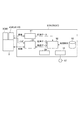
図2に示すように、制御装置(制御部)5は、画像処理装置51と、軌道生成装置52と、記憶装置53と、ロボットコントローラ54と、記録メディア読取装置55と、通信装置56と、を備えている。
As shown in FIG. 2, the control device (control unit) 5 includes an
画像処理装置51は、カメラ4で撮影した画像を基に撮影時点でのカメラ4からのワーク10の相対的な位置を計測する。計測法については、パターンマッチングやエッジを抽出して重心や交点などの特徴点を求める方法などがあるが、本実施形態では特に限定されない。なお、カメラがエンドエフェクタの代わりにロボットアームの先端に取り付けられている場合には、画像処理装置51は、ラベルの文字認識、ワークの表面状態の観測やワークの有無等の状態を観測する。
The
軌道生成装置52は、ワーク10に対して所定の作業を実行するための目標位置にエンドエフェクタ3を誘導するためのロボットアーム2の軌道を生成する装置である。具体的には、軌道生成装置52は、予め教示された教示点に基づいて、仮の目標位置までのロボットアーム2の軌道(以下、「アプローチ軌道」という)を生成する。また、軌道生成装置52は、ワーク10の近傍でカメラ4がワーク10を撮影可能な領域に到達すると、カメラ4の光軸に沿って光軸と平行にカメラ4が直線移動するようにロボットアーム2の軌道(以下、「平行軌道」という)を生成する。更に、軌道生成装置52は、目標位置が計測された後、仮の目標位置と計測された目標位置とがずれていた場合には計測された目標位置に基づいてアプローチ軌道を修正する。
The
なお、教示点の教示は、公知のティーチングペンダント(不図示)やパーソナルコンピュータ(不図示)などの入力装置から行われる。また、通常、教示点は誤差を含んでいるため、真の目標位置からずれている場合がある。この場合、教示点を仮の目標位置として、必要に応じて画像処理装置51からの情報を基にして、カメラ4の移動方向がカメラ4の光軸と平行からずれた場合は平行軌道等を修正できるようになっている。
The teaching point is taught from an input device such as a known teaching pendant (not shown) or a personal computer (not shown). In addition, since the teaching point usually includes an error, it may deviate from the true target position. In this case, if the moving direction of the
記憶装置53には、アプローチ軌道や平行軌道を生成するための各種プログラムや画像処理装置51により計測されたワーク10の位置情報の処理結果、予めユーザによって教示された初期教示点等のデータが格納されている。なお、記憶装置53は、ユーザインターフェイスに表示することで代替したり、省略することも可能である
The
ロボットコントローラ54は、軌道生成装置52が生成するアプローチ軌道や平行軌道に沿ってエンドエフェクタ3及びカメラ4が移動するようにロボットアーム2を駆動制御する。その際、フィードバック制御が用いられ、ロボットアーム2の現在位置情報を取得している。また、ロボットコントローラ54は、軌道生成装置52が生成した平行軌道に基づいてロボットアーム2が駆動中にカメラ4を撮影制御すると共に、目標位置に移動したエンドエフェクタ3を駆動制御する。本実施形態においては、カメラ4の移動方向がカメラ4の光軸と平行に直線移動(光軸に沿って移動)する平行軌道に乗った際にカメラ4に撮影指示を出すようになっている。なお、撮影指示は、カメラ4が平行軌道に乗った後であればいつでも可能であり、複数回の撮影を行う構成であってもよい。
The
記録メディア読取装置55は、ロボット制御プログラム等の各種プログラムを記録したコンピュータ読み取り可能な記録媒体57を読み込み、記録媒体57に記録されたプログラムやデータ等を記憶装置53に格納させるため等に用いられる。通信装置56は、例えば、上述したような記録媒体57を使用せずに、通信装置56を介してインターネット等から配信される更新プログラム等をダウンロードする際に用いられる。
The recording
なお、上述した画像処理装置51、軌道生成装置52及びロボットコントローラ54の実現手段は、マイクロコンピュータやゲートロジック、アナログ演算装置などを用いて実現することが可能であるが、上述の機能を満たせば特定の構成に限定されない。またハード的には1台のコンピュータで実現することも可能である。
The means for realizing the
次に、上述のように構成された制御装置5によるロボットアーム2の制御方法について、図3を参照しながら説明する。
Next, a method for controlling the
まず、軌道生成装置52により、ユーザによって予め入力された教示点、若しくは記憶装置53に記憶された初期教示点に基づいて、エンドエフェクタ3を仮の目標位置に誘導するアプローチ軌道が生成される。本実施形態においては、記憶装置53に記憶された初期教示点TPに基づいてアプローチ軌道が生成される。なお、アプローチ軌道の生成は、ユーザにより不図示の入力装置から入力される教示点に基づいて生成する構成であってもよい。
First, the
アプローチ軌道が生成されると、生成されたアプローチ軌道に沿ってエンドエフェクタ3及びカメラ4が移動するように、ロボットコントローラ54により、ロボットアーム2が駆動制御される。ロボットアーム2の駆動制御にはフィードバック制御が用いられ、ロボットアーム2の現在位置情報を取得しながら初期教示点TPに向かって駆動制御される。
When the approach trajectory is generated, the
次に、カメラ4がワーク10を撮影可能な範囲に移動すると、軌道生成装置52により、カメラ4が光軸と平行にワーク10に向かって直線移動(図3に示す直線lc)するように、平行軌道が生成される。平行軌道が生成されると、生成された平行軌道に沿ってエンドエフェクタ3及びカメラ4が移動するように、ロボットコントローラ54により、ロボットアーム2が駆動制御される(直線移動制御工程)。なお、カメラ4が直線lcに沿って移動する際のエンドエフェクタ3の軌道は、直線lcと平行な直線leのようになる。
Next, when the
次に、カメラ4が平行軌道に乗ると、ロボットコントローラ54は、カメラ4にトリガ信号を送信する。トリガ信号を受信すると、カメラ4は、光軸と平行にワーク10に向かって移動しながら初期教示点TP付近の撮影を行う。カメラ4で撮影された画像は、不図示の伝送ケーブル又は不図示の無線装置を伝って画像処理装置51に転送される。撮影が終わると、カメラ4は、露光(撮影)が終了したことを示すトリガ信号をロボットコントローラ54に送信する。
Next, when the
カメラ4からトリガ信号を受信すると、ロボットコントローラ54は、その時点でのロボットアーム2の位置データを記録し、軌道生成装置52へと転送する。なお、カメラ4からのトリガ信号の発信は、予めカメラの露光時間が分かっている場合には省略することができる。例えば、ロボットコントローラ54が有するタイマを使用して、露光終了時のロボットアーム2の位置データを記録すればよい。
When receiving the trigger signal from the
撮影された画像を受信すると、画像処理装置51は、受信した画像に基づいて、撮影した時点でのカメラ4からの相対的な目標位置を計測し、計測したデータを軌道生成装置52に転送する。軌道生成装置52は、ロボットコントローラ54から転送されたロボットアーム2の位置データ及び軌道生成装置52から転送された計測データを受信すると、ロボット座標に対する目標位置を計算する(ワーク位置計測工程)。この位置データと計測データとは同時刻のデータであり、ロボットアーム2の位置データからカメラ4のロボット座標に対する位置が決まるので、画像処理装置51からの計測データに加算することによってロボット座標に対する目標位置を計算することができる。
When the captured image is received, the
目標位置を計算すると、軌道生成装置52は、記憶装置53からロードされた初期教示点TPに対して、上記計算で得たデータをもってアプローチ軌道を修正し、目標位置に対する新たな軌道を計算する(軌道修正工程)。軌道の計算方法としては種々の方法が可能であるが、一般的な軌道の計算方法であればよく、特に計算方法に限定されるものではない。例えば、エンドエフェクタ3と目標位置とを最短距離で結ぶ方法、ロボットアーム2の関節の駆動量をできるだけ少なくする方法及び特異点を避けるアルゴリズムを組み合わせる方法などを用いることができる。
When the target position is calculated, the
なお、通常、画像処理や軌道計算には時間がかかるので、その間はアプローチ軌道を維持すればよい。また、アプローチ軌道の修正動作は、1度のみに限定されず、可能な限り複数回繰り返すことも可能である。 Note that image processing and trajectory calculation usually take time, and the approach trajectory may be maintained during that time. Further, the approach trajectory correcting operation is not limited to one time, and can be repeated as many times as possible.
計算された新たなアプローチ軌道は、軌道データとしてロボットコントローラ54に転送される。ロボットコントローラ54は、新たに生成されたアプローチ軌道に沿ってエンドエフェクタ3及びカメラ4が移動するように、ロボットアーム2を駆動制御する。また、これらの情報は、記憶装置53に転送され、ワーク10の計測情報として蓄積することができるようになっている。
The calculated new approach trajectory is transferred to the
次に、上述のように生成された平行軌道でカメラ4を移動させた際の効果について、図4を参照しながら説明する。まず、エンドエフェクタでワークに対して何らかの作業を行うためにはエンドエフェクタを正確な目標位置に誘導する必要がある。通常、教示時と実作業時のワークの位置は誤差を含むため、カメラで撮影した情報を基に目標位置を修正することが必要とされる。以下、平行軌道でカメラ4を移動させた際の効果について具体的に説明する。
Next, the effect when the
まず、カメラ4の撮像面上に光軸との交点を原点としたX軸及びY軸、撮像面と直交する方向(光軸方向)をZ軸としたカメラ座標系を設定する(図1参照)。撮影時tのカメラの各軸方向の速度を、それぞれVx(t)、Vy(t)、Vz(t)とし、カメラ4とワーク10の距離をW、カメラ4の焦点距離をf、撮像面上での計測点の位置をx,y、露光時間をTとする。すると、各軸方向に対するカメラ4の運動(運動方向)によるブレ量は、図4に示すようになる。
First, a camera coordinate system is set on the imaging surface of the
以下、Z軸方向の運動に対するX軸方向のブレについて説明する。なお、Y軸方向のブレに関しては、X軸方向のブレと同じ形の式になり、xをyに置き換えれば成り立つため説明を省略する。Z軸方向の運動に対するブレ量は、本来、 Hereinafter, blur in the X-axis direction with respect to movement in the Z-axis direction will be described. Note that the blur in the Y-axis direction has the same form as the blur in the X-axis direction, and will be omitted if x is replaced with y. The amount of motion blur in the Z-axis direction is essentially

ロボット本体6に搭載するカメラが大きい場合、ペイロードの増加や他の構造物との干渉を招くおそれがあるためカメラは小型に設計される。即ち、撮影距離に対してカメラのセンササイズは十分小さく設計され、x<<Wである。したがって、
When the camera mounted on the
例えば、カメラの焦点距離f=20mm、撮影距離W=100mm、各軸方向の運動速度Vx(t)=Vy(t)=Vz(t)=50mm/s、露光速度T=10msec、センサのピッチ2μm、撮像面上の計測位置x=1mmとする。すると、X軸方向の運動に対しては、撮像面上で中心から1mmの位置でのブレは0.1mm、すなわち、50画素分となり、影響が無視できなくなる。一方、Z軸方向の運動に対しては、撮像面上でのブレは1μm、すなわち0.5画素分にすぎなく、影響がほとんどない。 For example, camera focal length f = 20 mm, shooting distance W = 100 mm, movement speed Vx (t) = Vy (t) = Vz (t) = 50 mm / s in each axis direction, exposure speed T = 10 msec, sensor pitch Assume that the measurement position x on the imaging surface x is 1 mm. Then, for the movement in the X-axis direction, the blur at the position of 1 mm from the center on the imaging surface is 0.1 mm, that is, 50 pixels, and the influence cannot be ignored. On the other hand, the movement in the Z-axis direction has only 1 μm, that is, 0.5 pixels of blur on the imaging surface, and has almost no influence.
以上説明したように、第1実施形態に係るロボット装置1は、教示点に基づいて生成したアプローチ軌道にロボットアームを制御する際、カメラ4がワーク10に近づくと、ワーク10に向かってカメラ4が直線移動するようにロボットアーム2を駆動制御する。具体的には、カメラ4が光軸と平行に移動するようにロボットアーム2を駆動制御する。そして、カメラ4が光軸と平行に直線移動する間にカメラ4でワーク10を撮影する。そのため、ロボットアーム2を駆動中でもロボットアーム2に取り付けられたカメラ4のブレを小さくすることができる。これにより、ワークの位置や姿勢、又は部品の有無などの表面状態やラベルの認識等の計測の正確性を向上させることができる。
As described above, the
また、その際、ロボットアーム2を停止させることなくカメラの撮影を行うため、ロボットアーム2を再加速するための時間が不要になる。そのため、作業時間の短縮を図ることができる。
Further, at this time, since the camera is photographed without stopping the
なお、ここでいう平行とは数学的に厳密な平行でなくても、ほぼ平行で同等の効果を奏するものを含む。厳密な平行方向に対してずれが小さく、X,Y方向の運動成分がZ方向の運度に対して無視できるほど小さければよい。例えば、前記した例ではZ方向に100μm進む間にXY方向には、1μm進む程度の平行度のズレであれば、ほぼ同等の効果が得られる。 Note that the term “parallel” as used herein includes those that are substantially parallel and have the same effect even if they are not mathematically strictly parallel. It is sufficient that the deviation is small with respect to the strict parallel direction, and the motion components in the X and Y directions are small enough to be ignored with respect to the Z direction. For example, in the example described above, substantially the same effect can be obtained if the degree of parallelism shifts by about 1 μm in the XY direction while moving 100 μm in the Z direction.
<第2実施形態>
次に、本発明の第2実施形態について、図1及び図2を援用すると共に、図5を参照しながら説明する。第2実施形態に係るロボット装置1Aは、制御装置5Aによるエンドエフェクタ3及びカメラ4の軌道が第1実施形態と相違する。そのため、第2実施形態においては、第1実施形態と相違する点、即ち、エンドエフェクタ3及びカメラ4の軌道を中心に説明し、第1実施形態と同様の構成については説明を省略する。
Second Embodiment
Next, a second embodiment of the present invention will be described with reference to FIG. The
図1及び図2に示すように、ロボット装置1Aは、ロボット本体6と、カメラ4と、ロボット本体6及びカメラ4を制御可能な制御装置5Aと、を備えている。ロボット本体6は、ロボットアーム2と、エンドエフェクタ3と、を備えている。制御装置5Aは、画像処理装置51と、軌道生成装置52と、記憶装置53と、ロボットコントローラ54と、記録メディア読取装置55と、通信装置56と、を備えている。
As shown in FIGS. 1 and 2, the
次に、上述のように構成された制御装置5Aによるロボットアーム2の制御方法について、図5を参照しながら説明する。なお、カメラ4がワーク10を撮影可能な範囲に移動するまでは第1実施形態と同様であるため、ここではその説明は省略する。
Next, a method for controlling the
カメラ4がワーク10を撮影可能な領域に移動すると、軌道生成装置52により、カメラ4が光軸と平行にワーク10に向かって直線移動(図3に示す直線lc)するように、平行軌道が生成される。このとき、軌道生成装置52は、図5に示すように、少なくともカメラ4が撮影する位置までは初期教示点TPがカメラ4の光軸上に位置するように、平行軌道を形成する。
When the
初期教示点TPをカメラ4の光軸上に位置させると、初期教示点TPのカメラ4で撮影される画像位置はx=y=0なので、図4に示す式からZ方向の運動に対しての画像ブレは0となる。通常、測定対象点は、仮の測定点すなわち初期教示点付近に存在するので、この形態を実施すれば、第1実施形態より測定対象物のブレ量が少なくなり、高いぶれ防止効果を得ることができる。
When the initial teaching point TP is positioned on the optical axis of the
なお、撮影後のアプローチ軌道は、図5に示すleの曲線部のようにすることが好ましい。即ち、撮影するまでは直線移動し、その後、滑らかに軌道が変化するように曲線状に軌道を生成することが好ましい。 It is preferable that the approach trajectory after imaging is as shown by a curved portion of le shown in FIG. In other words, it is preferable that the trajectory is generated in a curved line so that the trajectory moves linearly until photographing and then the trajectory changes smoothly.
<第3実施形態>
次に、本発明の第3実施形態について、図1及び図2を援用すると共に、図6及び図7を参照しながら説明する。第3実施形態に係るロボット装置1Bは、エンドエフェクタ3の先端が写るように、エンドエフェクタ3に対して所定角度傾斜した状態でカメラ4が取り付けられている点が第1実施形態と相違する。そのため、第3実施形態においては、第1実施形態と相違する点、即ち、カメラ4の取付け状態を中心に説明し、第1実施形態と同様の構成については説明を省略する。
<Third Embodiment>
Next, a third embodiment of the present invention will be described with reference to FIGS. 6 and 7 while using FIGS. The
図1及び図2に示すように、ロボット装置1Bは、ロボット本体6と、カメラ4Bと、ロボット本体6及びカメラ4を制御可能な制御装置5Bと、を備えている。ロボット本体6は、ロボットアーム2と、エンドエフェクタ3Bと、を備えている。制御装置5Bは、画像処理装置51と、軌道生成装置52と、記憶装置53と、ロボットコントローラ54と、記録メディア読取装置55と、通信装置56と、を備えている。
As shown in FIGS. 1 and 2, the
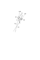
ここで、例えば、ドライバやディスペンサなど、一般にエンドエフェクタは作業姿勢に限定があるものがほとんどである。つまり、エンドエフェクタでの作業には方向性があり、作業時にはエンドエフェクタに特定の姿勢を取らせる必要がある。そこで、本実施形態では、図6及び図7に示すように、カメラ4Bがエンドエフェクタ3Bに対して適当な仰角を持ち、常にその画角にエンドエフェクタ3Bの先端が映るようにロボットアーム2の先端に固定されている。
Here, for example, most end effectors, such as drivers and dispensers, generally have a limited working posture. That is, the work with the end effector is directional, and it is necessary to make the end effector take a specific posture during the work. Therefore, in the present embodiment, as shown in FIGS. 6 and 7, the
なお、ここでいう仰角とは、カメラ4Bの光軸と、エンドエフェクタ(例えば、ドライバ)3Bの作業方向とがなす角θである。すなわち、エンドエフェクタ3Bが作業時に作業部位が写るように作業方向に対してカメラ4Bが側方から覗き込む角度のことである。また、エンドエフェクタ3Bの作業方向とは、例えば、ドライバを例に示すとネジが進む方向、すなわち主軸方向である。通常は、適当な仰角を付けることによって光軸付近にエンドエフェクタ3Bの作業点が位置するように設置される。
The elevation angle here is an angle θ formed by the optical axis of the
このように、エンドエフェクタ3Bの先端が映るようにカメラ4Bを取り付けることで、図7に示すように、作業対象にアプローチする際、エンドエフェクタ3Bを作業時の姿勢に保つことが可能になり、動作の無駄を無くすことができる。例えば、図12に示す従来例のように、最短距離でワーク110にアプローチする場合、遠距離では初期教示点TPが画角に入らない上に、画角に入った後も画像上での初期教示点TPの位置が大きく動いてしまい、大きなブレが生じてしまう。これに対して第3実施形態では、エンドエフェクタ3Bの姿勢を保ったまま、カメラ4Bの設置された仰角方向からエンドエフェクタ3Bの先端を進入させる軌道をとる。こうすることによって、カメラ4Bはその光軸方向と平行に運動することとなり、第1実施形態と同様にして、平行軌道に乗った以降であればいつ撮影しても、撮影する際のブレを小さく抑えることができる。また、例えば、図13に示す従来例のように、ワークがずれていなかった場合にエンドエフェクタ104を大きく動かす等の必要がなくなる。
In this way, by attaching the
なお、教示点が光軸上にあるように軌道をとれば、教示点の画像上でのブレを0とすることが可能である。また、さらにエンドエフェクタの作用点も光軸上にあるようにロボットアームの先端に固定すると、エンドエフェクタの作用点と教示点付近にある真の目標点を一致させるような画像サーボ動作に用いることができる。 Note that if the trajectory is taken so that the teaching point is on the optical axis, the blurring of the teaching point on the image can be reduced to zero. If the end effector's point of action is fixed on the tip of the robot arm so that it is on the optical axis, the end effector's point of action and the true target point near the teaching point should be used for image servo operation. Can do.
<第4実施形態>
次に、本発明の第4実施形態について、図2を援用すると共に、図8から図11を参照しながら説明する。第4実施形態に係るロボット装置1Cは、2眼のステレオカメラを用いる点が第1実施形態と相違する。そのため、第4実施形態においては、ステレオカメラを用いた場合を中心に説明し、第1実施形態と同様の構成については説明を省略する。
<Fourth embodiment>
Next, a fourth embodiment of the present invention will be described with reference to FIGS. The
図8に示すように、ロボット装置1Cは、ロボット本体6と、ロボット本体6に取り付けられたカメラ42,43と、ロボット本体6及びカメラ42,43を制御可能な制御装置5Cと、を備えている。ロボット本体6は、ロボットアーム2と、エンドエフェクタ3と、を備えている。
As shown in FIG. 8, the
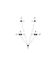
図9に示すように、カメラ42,43は、相互に所定の基線長を保ってロボットアーム2に固定されており、公知のステレオ計測を行うことによってワーク10の3次元の位置姿勢を検出することが可能なステレオカメラ41である。また、図9に示すlc22はカメラ42の焦点と初期教示点TPを通る直線であり、lc23はカメラ43の焦点と初期教示点TPを通る直線である。図9に示すPcは、2つの直線lc22,lc23が張る平面であり、言い換えると、カメラ42の焦点と、カメラ43の焦点と、初期教示点TPとから構成される平面である。この平面は、通常、エピポーラ面Pcと呼ばれ、ロボットアーム2の先端の軌道は、このエピポーラ面Pcと平行になるように軌道生成装置52によって生成される。
As shown in FIG. 9, the
次に、エピポーラ面Pcと平行にカメラ42,43を移動させた場合の効果について、図10を参照しながら説明する。図10に示す44はカメラ42で撮影された画像であり、25はカメラ43で撮影された画像である。また、tp44,tp55はそれぞれ教示点の画像44、画像45上での位置及びブレを示している。本実施形態の場合、計測点の像は常に同一のエピポーラ面上にあるように制御されるため、図10に図示したようにブレは特定の方向、すなわち、いわゆるエピポーラ線上に限定して発生する。
Next, the effect when the
また、作業時には、ロボットアーム2の先端及びカメラ42,43は教示点に近接するため、公知のステレオ計測の原理によりブレにより発する輝線のうち、もっとも視差の大きい点が最終的な位置を表す。例えば、図11において、O点は計測点を示し、点A、点Bは、カメラ42,43が露光を開始する点での計測点Oの像を示し、点A”、点B”は、カメラ42,43が露光を終了する点での計測点Oの像を示している。また、線分A’A”及び線分B’B”は露光終了時に計測点に相当する像のブレを示している。図11に示すように、カメラが計測点Oに最も近づいた時、すなわちA”,B”の組が視差が最も大きくなっていることが分かる。このように、ブレ像のうち最も視差が大きくなる点が最新の位置を示しているため、この位置は容易に限定でき、またこの位置をもって計測を行えば、もっとも最新の情報を得ることができる。
At the time of work, since the tip of the
以上説明したように、第3実施形態によれば、ブレが発生した場合でも、容易に正確な三次元の目標位置を検出することが可能となり、動きながらの3次元位置計測が可能になる。 As described above, according to the third embodiment, even when blurring occurs, it is possible to easily detect an accurate three-dimensional target position, and it is possible to measure a three-dimensional position while moving.
なお、軌道の方向として、さらに2つのカメラの焦点を結ぶ線の垂直2等分線と平行とすれば、片方のカメラのみ大きくぶれることがなくなり、より好ましい。また、軌道の方向として、さらに片方のカメラの光軸上に教示点が乗るように生成すれば、そちらのカメラのブレを、ほぼなくすことができる。したがってこの場合は、3次元の位置計測の他に光軸上に教示点が乗るように設定されたカメラ側でテクスチャなど表面状態をブレなく観測することが可能となる。 Note that it is more preferable that the direction of the trajectory be parallel to a perpendicular bisector of a line connecting the focal points of the two cameras, so that only one of the cameras is not greatly shaken. Further, if the direction of the trajectory is generated so that the teaching point is on the optical axis of one of the cameras, the camera shake can be almost eliminated. Therefore, in this case, in addition to the three-dimensional position measurement, it is possible to observe the surface state such as texture without blur on the camera side set so that the teaching point is placed on the optical axis.
1、1A、1B、1C ロボット装置
2 ロボットアーム
3、3B エンドエフェクタ
4 カメラ
5、5A、5B、5C 制御装置(制御部)
6 ロボット本体
10 ワーク
1, 1A, 1B,
6
Claims (10)
前記ロボット本体に取り付けられ、対象物を撮影するカメラと、
予め設定された教示点までの軌道に基づいて、前記対象物に向けて前記カメラが前記カメラの光軸に沿って直線移動するように前記ロボット本体を駆動させると共に、前記カメラが直線移動している間に前記カメラで前記対象物を撮影し、撮影した画像から前記対象物の位置を計測する制御装置と、を備えた、
ことを特徴とするロボット装置。 The robot body,
A camera attached to the robot body and shooting an object;
Based on the track until the preset teaching point, Rutotomoni the robot body is driven so that the camera toward the object is linearly moved along the optical axis of the camera, the camera moves linearly A control device for photographing the object with the camera while measuring the position of the object from the photographed image,
A robot apparatus characterized by that.
ことを特徴とする請求項1に記載のロボット装置。 The controller drives the robot body so that the teaching point is located on the optical axis of the camera when the camera reaches an area where the object can be photographed.
The robot apparatus according to claim 1.
前記カメラは、前記エンドエフェクタの先端が写るように、前記エンドエフェクタに対して所定角度傾斜した状態で前記ロボットアーム又は前記エンドエフェクタに取り付けられている、
ことを特徴とする請求項1又は2に記載のロボット装置。 The robot body includes a robot arm, and an end effector that is attached to a tip of the robot arm and performs a predetermined operation.
The camera is attached to the robot arm or the end effector in a state inclined at a predetermined angle with respect to the end effector so that the tip of the end effector is reflected.
The robot apparatus according to claim 1 or 2, wherein
前記ロボット本体に取り付けられ、対象物を撮影するステレオカメラと、
予め設定された教示点までの軌道に基づいて、前記対象物に向けて前記ステレオカメラが前記ステレオカメラの2つの焦点と前記予め設定された教示点とが通る平面から構成されるエピポーラ面に沿って直線移動するように前記ロボット本体を駆動すると共に、前記ステレオカメラが直線移動している間に前記ステレオカメラで前記対象物を撮影し、撮影した画像から前記対象物の3次元位置を計測する制御装置と、を備えた、
ことを特徴とするロボット装置。 The robot body,
A stereo camera attached to the robot body for photographing an object;
Based on the track until the preset teaching point, along the epipolar plane composed of two focus and the preset teaching point and passes the plane of the stereo camera toward the object the stereo camera The robot body is driven so as to move linearly, and the object is photographed by the stereo camera while the stereo camera is moving linearly, and the three-dimensional position of the object is measured from the photographed image. A control device,
A robot apparatus characterized by that.
ことを特徴とする請求項1から4のいずれか1項に記載のロボット装置。 The control device corrects the trajectory of the robot body based on the measured position of the object.
The robot apparatus according to any one of claims 1 to 4, wherein the robot apparatus is characterized.
前記制御部が、前記カメラが直線移動している間に前記カメラで前記対象物を撮影しつつ、撮影した画像から前記対象物の位置を計測する対象物位置計測工程と、を備えた、
ことを特徴とするロボット制御方法。 While the controller is driving the robot body based on the trajectory up to a preset teaching point, when the camera attached to the robot body reaches an area where the object can be photographed, A linear movement control step of driving the robot body so that the camera linearly moves along the optical axis of the camera ,
The control unit includes an object position measuring step of measuring the position of the object from the captured image while capturing the object with the camera while the camera is moving linearly.
A robot control method characterized by the above.
前記制御部が、前記ステレオカメラが直線移動している間に前記ステレオカメラで前記対象物を撮影しつつ、撮影した画像から前記対象物の3次元位置を計測する3次元位置計測工程と、を備えた、 A three-dimensional position measuring step of measuring the three-dimensional position of the object from the captured image while the controller captures the object with the stereo camera while the stereo camera is moving linearly; Prepared,
ことを特徴とするロボット制御方法。 A robot control method characterized by the above.
ことを特徴とする請求項6又は7に記載のロボット制御方法。 The robot control method according to claim 6 or 7, wherein
Priority Applications (3)
| Application Number | Priority Date | Filing Date | Title |
|---|---|---|---|
| JP2013126680A JP6188440B2 (en) | 2013-06-17 | 2013-06-17 | Robot apparatus and robot control method |
| US14/296,030 US9393696B2 (en) | 2013-06-17 | 2014-06-04 | Robot system and robot control method |
| CN201410259247.5A CN104227722B (en) | 2013-06-17 | 2014-06-12 | Robot system and robot control method |
Applications Claiming Priority (1)
| Application Number | Priority Date | Filing Date | Title |
|---|---|---|---|
| JP2013126680A JP6188440B2 (en) | 2013-06-17 | 2013-06-17 | Robot apparatus and robot control method |
Publications (3)
| Publication Number | Publication Date |
|---|---|
| JP2015000454A JP2015000454A (en) | 2015-01-05 |
| JP2015000454A5 JP2015000454A5 (en) | 2016-07-28 |
| JP6188440B2 true JP6188440B2 (en) | 2017-08-30 |
Family
ID=52019906
Family Applications (1)
| Application Number | Title | Priority Date | Filing Date |
|---|---|---|---|
| JP2013126680A Active JP6188440B2 (en) | 2013-06-17 | 2013-06-17 | Robot apparatus and robot control method |
Country Status (3)
| Country | Link |
|---|---|
| US (1) | US9393696B2 (en) |
| JP (1) | JP6188440B2 (en) |
| CN (1) | CN104227722B (en) |
Families Citing this family (28)
| Publication number | Priority date | Publication date | Assignee | Title |
|---|---|---|---|---|
| US20110209320A1 (en) * | 2010-02-26 | 2011-09-01 | Abb Inc. | Vision Guided Robotic Grommet Installation |
| US9656390B2 (en) * | 2014-11-10 | 2017-05-23 | Faro Technologies, Inc. | Human-centric robot with noncontact measurement device |
| CN104608137B (en) * | 2015-02-09 | 2016-08-24 | 江苏科沁光电科技有限公司 | A kind of four axle robot systems of band vision |
| CN104950816A (en) * | 2015-06-29 | 2015-09-30 | 贵州桂荣科技有限公司 | Intelligent coding control method of electronic bracelet assembling equipment |
| US10335951B2 (en) * | 2015-07-29 | 2019-07-02 | Canon Kabushiki Kaisha | Information processing apparatus, information processing method, robot control apparatus, and robot system |
| WO2017033367A1 (en) * | 2015-08-25 | 2017-03-02 | 川崎重工業株式会社 | Remote control robot system |
| US10875186B2 (en) | 2015-09-03 | 2020-12-29 | Fuji Corporation | Robot system |
| US9418421B1 (en) * | 2015-09-26 | 2016-08-16 | Nastaran Neishaboori | Automation of biopsy specimen handling |
| CN105364926A (en) * | 2015-11-20 | 2016-03-02 | 上海新时达电气股份有限公司 | Multi-shaft robot driving and controlling integrated control system |
| CN105500330B (en) * | 2015-12-01 | 2018-01-12 | 南陵旺科知识产权运营有限公司 | The transport vehicle of unpiloted electromechanical integration |
| JP6714393B2 (en) * | 2016-03-02 | 2020-06-24 | キヤノン株式会社 | Measuring device, system, measuring method, and article manufacturing method |
| FR3054154B1 (en) * | 2016-07-21 | 2019-05-10 | Europe Technologies | ROBOTISE DRYING METHOD AND ROBOTIC SYSTEM FOR IMPLEMENTING THE METHOD |
| JP6514156B2 (en) | 2016-08-17 | 2019-05-15 | ファナック株式会社 | Robot controller |
| CN106679563B (en) * | 2016-12-13 | 2019-05-07 | 广州视源电子科技股份有限公司 | Method and device for determining needle box position of board card to be tested |
| JP2019058993A (en) * | 2017-09-27 | 2019-04-18 | セイコーエプソン株式会社 | Robot system |
| US11358290B2 (en) * | 2017-10-19 | 2022-06-14 | Canon Kabushiki Kaisha | Control apparatus, robot system, method for operating control apparatus, and storage medium |
| JP7323993B2 (en) * | 2017-10-19 | 2023-08-09 | キヤノン株式会社 | Control device, robot system, operating method and program for control device |
| CN107876269B (en) * | 2017-12-25 | 2023-06-16 | 厦门大学嘉庚学院 | Tri-vision visual spraying track extraction system for automatic spraying of shoe mold and working method thereof |
| CN108527319B (en) * | 2018-03-28 | 2024-02-13 | 广州瑞松北斗汽车装备有限公司 | Robot teaching method and system based on vision system |
| DE102018109329B4 (en) * | 2018-04-19 | 2019-12-05 | Gottfried Wilhelm Leibniz Universität Hannover | Multi-unit actuated kinematics, preferably robots, particularly preferably articulated robots |
| US11040452B2 (en) * | 2018-05-29 | 2021-06-22 | Abb Schweiz Ag | Depth sensing robotic hand-eye camera using structured light |
| CN109309791B (en) * | 2018-11-09 | 2021-01-29 | 珠海格力智能装备有限公司 | Method and system for controlling camera to take pictures |
| JP6878391B2 (en) * | 2018-12-18 | 2021-05-26 | ファナック株式会社 | Robot system and its adjustment method |
| CN109919976B (en) * | 2019-02-25 | 2023-01-17 | 太仓中科信息技术研究院 | Camera robot-based scene automatic multiplexing method, device and storage medium |
| JP6717401B1 (en) * | 2019-04-01 | 2020-07-01 | 株式会社安川電機 | Programming support device, robot system, and programming support method |
| JP2020196059A (en) * | 2019-05-31 | 2020-12-10 | セイコーエプソン株式会社 | robot |
| WO2021012124A1 (en) * | 2019-07-19 | 2021-01-28 | 西门子(中国)有限公司 | Robot hand-eye calibration method and apparatus, computing device, medium and product |
| KR102492922B1 (en) * | 2022-03-03 | 2023-01-30 | 인팩일렉스 주식회사 | PCB board electronic compont bonding system electricity car |
Family Cites Families (22)
| Publication number | Priority date | Publication date | Assignee | Title |
|---|---|---|---|---|
| US4891767A (en) * | 1988-06-02 | 1990-01-02 | Combustion Engineering, Inc. | Machine vision system for position sensing |
| JPH04365586A (en) | 1991-06-14 | 1992-12-17 | Toyota Autom Loom Works Ltd | Optical axis aligning method and orthogonal axis aligning method for hand eye |
| JPH0699381A (en) * | 1992-09-22 | 1994-04-12 | Hitachi Koki Co Ltd | Control method for robot provided with visual sensor |
| JPH0847881A (en) * | 1994-08-05 | 1996-02-20 | Ishikawajima Harima Heavy Ind Co Ltd | Method of remotely controlling robot |
| JPH08241109A (en) | 1995-03-03 | 1996-09-17 | Nippon Telegr & Teleph Corp <Ntt> | Light projection device for body setting and automatic operating device using same |
| JP3998741B2 (en) * | 1995-07-12 | 2007-10-31 | ファナック株式会社 | Robot movement control method |
| JPH0947991A (en) * | 1995-08-01 | 1997-02-18 | Mitsubishi Heavy Ind Ltd | Method and device of processing visual information for industrial robot |
| JP3768665B2 (en) | 1997-12-12 | 2006-04-19 | キヤノン株式会社 | Frequency signal generation circuit and vibration actuator driving device |
| US6229402B1 (en) | 1998-05-28 | 2001-05-08 | Canon Kabushiki Kaisha | Driving circuit for vibration type actuator apparatus |
| JP3300682B2 (en) | 1999-04-08 | 2002-07-08 | ファナック株式会社 | Robot device with image processing function |
| US6194860B1 (en) * | 1999-11-01 | 2001-02-27 | Yoder Software, Inc. | Mobile camera-space manipulation |
| JP2003326485A (en) | 2002-05-08 | 2003-11-18 | Mitsubishi Heavy Ind Ltd | Manipulator with sensor for capture |
| JP4167940B2 (en) * | 2003-05-29 | 2008-10-22 | ファナック株式会社 | Robot system |
| JP4167954B2 (en) * | 2003-09-02 | 2008-10-22 | ファナック株式会社 | Robot and robot moving method |
| JP4309439B2 (en) | 2007-03-30 | 2009-08-05 | ファナック株式会社 | Object take-out device |
| CN101372098A (en) * | 2007-08-23 | 2009-02-25 | 株式会社Ihi | Robot device and control method thereof |
| JP2009241247A (en) * | 2008-03-10 | 2009-10-22 | Kyokko Denki Kk | Stereo-image type detection movement device |
| JP5233601B2 (en) | 2008-11-07 | 2013-07-10 | セイコーエプソン株式会社 | Robot system, robot control apparatus, and robot control method |
| US9279661B2 (en) * | 2011-07-08 | 2016-03-08 | Canon Kabushiki Kaisha | Information processing apparatus and information processing method |
| JP6032564B2 (en) * | 2011-09-22 | 2016-11-30 | パナソニックIpマネジメント株式会社 | Stereoscopic imaging device and stereoscopic imaging method |
| CN102736626B (en) | 2012-05-11 | 2014-08-20 | 北京化工大学 | Vision-based pose stabilization control method of moving trolley |
| US8913825B2 (en) * | 2012-07-16 | 2014-12-16 | Mitsubishi Electric Research Laboratories, Inc. | Specular edge extraction using multi-flash imaging |
-
2013
- 2013-06-17 JP JP2013126680A patent/JP6188440B2/en active Active
-
2014
- 2014-06-04 US US14/296,030 patent/US9393696B2/en active Active
- 2014-06-12 CN CN201410259247.5A patent/CN104227722B/en active Active
Also Published As
| Publication number | Publication date |
|---|---|
| JP2015000454A (en) | 2015-01-05 |
| US9393696B2 (en) | 2016-07-19 |
| US20140371910A1 (en) | 2014-12-18 |
| CN104227722B (en) | 2017-05-31 |
| CN104227722A (en) | 2014-12-24 |
Similar Documents
| Publication | Publication Date | Title |
|---|---|---|
| JP6188440B2 (en) | Robot apparatus and robot control method | |
| JP6420229B2 (en) | A robot system including a video display device that superimposes and displays an image of a virtual object on a video of a robot | |
| JP6180087B2 (en) | Information processing apparatus and information processing method | |
| EP2682711B1 (en) | Apparatus and method for three-dimensional measurement and robot system comprising said apparatus | |
| JP4819957B1 (en) | Robot position information restoration apparatus and position information restoration method | |
| JP6317618B2 (en) | Information processing apparatus and method, measuring apparatus, and working apparatus | |
| WO2018145476A1 (en) | Image acquisition method and device | |
| WO2021012124A1 (en) | Robot hand-eye calibration method and apparatus, computing device, medium and product | |
| JP2013036987A (en) | Information processing device and information processing method | |
| JP2015136770A (en) | Data creation system of visual sensor, and detection simulation system | |
| CN112549052B (en) | Control device for robot device for adjusting position of robot-supported component | |
| JP2024009106A (en) | Device and method for acquiring deviation amount of work position of tool | |
| CN114174006A (en) | Robot eye calibration method, device, computing equipment, medium and product | |
| JP2019119027A (en) | Method of controlling robot system, and robot system | |
| US20190030722A1 (en) | Control device, robot system, and control method | |
| JP5686279B2 (en) | Work posture detection device, work processing execution device, and work posture detection method | |
| US20230123629A1 (en) | 3d computer-vision system with variable spatial resolution | |
| CN107921643B (en) | Robot system | |
| JP6410411B2 (en) | Pattern matching apparatus and pattern matching method | |
| JP2008168372A (en) | Robot device and shape recognition method | |
| JP7323993B2 (en) | Control device, robot system, operating method and program for control device | |
| KR20130075712A (en) | A laser-vision sensor and calibration method thereof | |
| JP2011083883A (en) | Robot device | |
| CN112566758A (en) | Robot control device, robot control method, and robot control program | |
| WO2016151667A1 (en) | Teaching device and method for generating control information |
Legal Events
| Date | Code | Title | Description |
|---|---|---|---|
| A521 | Written amendment |
Free format text: JAPANESE INTERMEDIATE CODE: A523 Effective date: 20160607 |
|
| A621 | Written request for application examination |
Free format text: JAPANESE INTERMEDIATE CODE: A621 Effective date: 20160607 |
|
| A977 | Report on retrieval |
Free format text: JAPANESE INTERMEDIATE CODE: A971007 Effective date: 20170208 |
|
| A131 | Notification of reasons for refusal |
Free format text: JAPANESE INTERMEDIATE CODE: A131 Effective date: 20170214 |
|
| A521 | Written amendment |
Free format text: JAPANESE INTERMEDIATE CODE: A523 Effective date: 20170414 |
|
| TRDD | Decision of grant or rejection written | ||
| A01 | Written decision to grant a patent or to grant a registration (utility model) |
Free format text: JAPANESE INTERMEDIATE CODE: A01 Effective date: 20170704 |
|
| A61 | First payment of annual fees (during grant procedure) |
Free format text: JAPANESE INTERMEDIATE CODE: A61 Effective date: 20170801 |
|
| R151 | Written notification of patent or utility model registration |
Ref document number: 6188440 Country of ref document: JP Free format text: JAPANESE INTERMEDIATE CODE: R151 |