JP7323993B2 - Control device, robot system, operating method and program for control device - Google Patents
Control device, robot system, operating method and program for control device Download PDFInfo
- Publication number
- JP7323993B2 JP7323993B2 JP2018182701A JP2018182701A JP7323993B2 JP 7323993 B2 JP7323993 B2 JP 7323993B2 JP 2018182701 A JP2018182701 A JP 2018182701A JP 2018182701 A JP2018182701 A JP 2018182701A JP 7323993 B2 JP7323993 B2 JP 7323993B2
- Authority
- JP
- Japan
- Prior art keywords
- controlled object
- image
- target position
- control
- motion
- Prior art date
- Legal status (The legal status is an assumption and is not a legal conclusion. Google has not performed a legal analysis and makes no representation as to the accuracy of the status listed.)
- Active
Links
Images


Description
本発明は、制御装置、ロボットシステム、制御装置の動作方法及びプログラムに関し、特に、画像に基づいてロボットを制御するビジュアルサーボ技術に関する。 The present invention relates to a control device, a robot system, an operation method and program for the control device, and more particularly to visual servo technology for controlling a robot based on images.
従来、カメラ画像に基づいてロボットの制御を行う手法の一つとして、ビジュアルサーボが知られている。ビジュアルサーボとは、所望の位置に対象物体が写るようにロボットをフィードバック制御する技術である。ビジュアルサーボを用いると、ロボットとカメラとの間やロボットとエンドエフェクタとの間の位置姿勢関係を精度よく求めておく必要がなく、それらの位置関係を求めるキャリブレーション作業の負荷を低減することができる。中でも、目標位置へ誘導する対象や目標位置にある対象の特徴を画像から抽出し、それらの位置の差に基づいてロボットを制御する手法は、誘導する対象や目標位置にある対象の位置変化に対応できる利点がある。 Conventionally, visual servoing is known as one method of controlling a robot based on camera images. Visual servoing is a technology that feedback-controls a robot so that a target object appears at a desired position. Using visual servos eliminates the need to accurately determine the position and orientation relationships between the robot and the camera and between the robot and the end effector, reducing the burden of calibration work to determine these positional relationships. can. Among them, the method of extracting the characteristics of the object to be guided to the target position and the object at the target position from the image and controlling the robot based on the difference in those positions is a method that can be used to control the position of the target to be guided and the target position. There are advantages that can be accommodated.
特許文献1では、組付け対象物と被組付け対象物とを撮像した画像から特徴量検出を行い、検出結果に基づいて組付け作業をすることで、被組付け対象物が位置ずれしている場合でも組付け作業を実現することが開示されている。 In Japanese Patent Laid-Open No. 2002-100000, feature amounts are detected from images of an object to be assembled and an object to be assembled, and the assembly work is performed based on the detection results. It is disclosed that the assembling work can be realized even when there is a
画像特徴を使ったビジュアルサーボを実現するためには、目標位置へ誘導する対象と目標位置にある対象とを同じ画像中に撮像すると共に、それぞれ複数の特徴を抽出することで位置姿勢を特定できるようにする必要がある。しかしながら、物体の形状によっては少ない特徴しか抽出することができないことがある。また、カメラの配置によっても物体の一部しか見えないため特徴を十分に抽出できないことがある。 In order to realize visual servoing using image features, the target to be guided to the target position and the target at the target position are imaged in the same image, and the position and orientation can be specified by extracting multiple features for each. It is necessary to However, depending on the shape of the object, only a few features can be extracted. Also, depending on the arrangement of the camera, only a part of the object can be seen, and the features may not be sufficiently extracted.
本発明は、上記の課題に鑑みてなされたものであり、画像から十分に特徴を抽出できない場合においてもビジュアルサーボを実現して高精度にタスクを実行可能にするための技術を提供することを目的とする。 SUMMARY OF THE INVENTION The present invention has been made in view of the above-mentioned problems, and aims to provide a technique for realizing visual servoing and enabling tasks to be executed with high accuracy even when sufficient features cannot be extracted from an image. aim.
上記の目的を達成する本発明に係る制御装置は、
ロボットに取り付けられた撮像装置により、前記ロボットが回転制御可能な制御対象及び前記制御対象の移動先である目標位置であって凹部にある目標の位置である前記目標位置を撮像した画像を取得する画像取得手段と、
前記画像における前記制御対象のエッジに基づいて、前記制御対象の回転軸の進行方向であって前記制御対象の回転軸に沿っている前記進行方向を表す該画像中の2次元方向を取得する進行方向取得手段と、
前記画像から前記目標位置を表す該画像中の2次元位置を検出する目標位置検出手段と、
前記回転軸の進行方向の延長上に前記目標位置が存在し、前記回転軸の進行方向と前記凹部の深さ方向とが一致するように前記制御対象の姿勢を変更する動作を前記制御対象が前記目標位置に達する前に生成し、さらに姿勢を変更した制御対象の進行方向に沿って前記制御対象を前記目標位置に近づける動作を生成する動作生成手段と、
前記動作に従って前記制御対象を制御する制御手段と、
を備え、
前記動作生成手段は、前記2次元方向に沿った線分と前記2次元位置とを近づける前記制御対象の姿勢の制御量を求め、該制御量に基づいて前記制御対象の姿勢を更新することを特徴とする。
A control device according to the present invention that achieves the above objects includes:
An imaging device attached to a robot acquires an image of a controlled object whose rotation can be controlled by the robot and a target position, which is a destination of movement of the controlled object, and is a target position in a concave portion. an image acquisition means;
A progression for acquiring a two-dimensional direction in the image representing the traveling direction of the rotational axis of the controlled object and along the rotational axis of the controlled object, based on the edges of the controlled object in the image. a direction acquisition means;
target position detection means for detecting a two-dimensional position in the image representing the target position from the image ;
The target position exists on the extension of the traveling direction of the rotating shaft, and the controlled object performs an operation of changing the attitude of the controlled object so that the traveling direction of the rotating shaft and the depth direction of the recess match. a motion generation means for generating a motion of moving the controlled object closer to the target position along the traveling direction of the controlled object whose attitude has been changed, which is generated before reaching the target position;
a control means for controlling the controlled object according to the operation;
with
The motion generating means obtains a control amount of the posture of the control object that brings the line segment along the two-dimensional direction closer to the two-dimensional position, and updates the posture of the control object based on the control amount. characterized by
本発明によれば、画像から十分に特徴を抽出できない場合においてもビジュアルサーボを実現して高精度にタスクを実行することが可能となる。 According to the present invention, it is possible to implement visual servoing and execute tasks with high accuracy even when sufficient features cannot be extracted from an image.
以下、図面を参照しながら実施形態を説明する。なお、以下の実施形態において示す構成は一例に過ぎず、本発明は図示された構成に限定されるものではない。 Hereinafter, embodiments will be described with reference to the drawings. Note that the configurations shown in the following embodiments are merely examples, and the present invention is not limited to the illustrated configurations.
(第1の実施形態)
第1の実施形態では、ロボットに取り付けた撮像装置で、制御対象と目標位置とを撮像し、ロボットにより制御対象を目標位置まで誘導する。本実施形態では、制御対象とはロボットに装着したエンドエフェクタであるドライバである。目標位置とはエンドエフェクタがタスクを実行する位置のことで、本実施形態では画像特徴1点の位置であるネジ中心を用いる。なお、目標位置は2点以上の画像特徴でもよい。ロボットによるタスクとして誘導後にエンドエフェクタであるドライバを用いてネジを取り外すことで、自動でネジを外すロボットシステムについても説明する。画像中のドライバとネジとの位置関係からロボットの動作を生成することで、ロボットと撮像装置とのキャリブレーションあるいは撮像装置とエンドエフェクタとのキャリブレーションに誤差がある場合でも、正確に制御できる。
(First embodiment)
In the first embodiment, an imaging device attached to a robot captures an image of a controlled object and a target position, and the robot guides the controlled object to the target position. In this embodiment, the controlled object is a driver, which is an end effector attached to the robot. The target position is the position at which the end effector executes the task, and in this embodiment, the screw center, which is the position of one image feature point, is used. Note that the target position may be two or more image features. A robot system that automatically unscrews screws by using a screwdriver, which is an end effector, to remove screws after being guided as a task by the robot will also be described. By generating the motion of the robot from the positional relationship between the driver and the screw in the image, it is possible to accurately control even if there is an error in the calibration between the robot and imaging device or between the imaging device and end effector.
[装置の構成]
図1の構成図および図2のブロック図により第1の実施形態の制御装置100を備えるロボットシステム1000の構成例を示す。ロボットシステム1000は、撮像装置1と、ロボットアーム2と、エンドエフェクタ3と、制御装置100とを備える。
[Device configuration]
The configuration diagram of FIG. 1 and the block diagram of FIG. 2 show a configuration example of a
撮像装置1は、エンドエフェクタ3に取り付けられ、エンドエフェクタ3および目標位置を含むシーンを撮像する装置である。たとえば、撮像装置1は2台のグレースケールカメラから構成され、制御部106からの撮像トリガにより撮像を行い、画像取得部101に画像信号を送る。
The imaging device 1 is a device that is attached to the
ロボットアーム2は、制御対象を移動させる装置である。たとえばロボットアーム2は6軸ロボットから構成され、制御装置100により制御値を入力されて動作する。エンドエフェクタ3は、ロボットアームの先端に取り付けられた、目標を操作する装置である。たとえば、エンドエフェクタ3はドライバおよび近接センサから構成され、制御装置100にドライバと目標との接触状態を入力する。また、エンドエフェクタ3は制御装置100により制御値を入力されて動作する。
The
制御装置100は、画像取得部101と、軸方向取得部102と、目標位置検出部103と、動作生成部104と、終了判断部105と、制御部106とを備える。
The
画像取得部101は、撮像装置1から画像信号を受け取り、軸方向取得部102及び目標位置検出部103に画像データを送る。たとえば画像取得部101はメモリから構成される。
The
軸方向取得部102は、画像取得部101から画像データを受け取り、図示しない軸方向設定部により設定された制御対象の軸方向を取得し、軸方向データを動作生成部104及び終了判断部105に送る。ここで、軸とは例えば回転軸であり、軸方向とは、制御対象と目標位置との位置姿勢関係を測るための制御対象に関連付けられた画像中の線分のことで、たとえばエンドエフェクタ3であるドライバの中心軸を、軸上の2次元点と、根本から先端に向かう2次元ベクトルとで表す。なお、ベクトルは逆に先端から根本に向かう方向でもよい。軸方向を設定することで、エンドエフェクタ3に取り付けられた撮像装置1ではエンドエフェクタ3を部分的にしか撮像できず、十分にエンドエフェクタ3の特徴を検出できない状況であっても、動作生成部104がロボットアーム2の先端部の動作を規定する位置姿勢を計算することができる。
The axial
目標位置検出部103は、画像取得部101から画像データを受け取り、画像データから目標位置を検出し、目標位置データを動作生成部104及び終了判断部105に送る。動作生成部104は、軸方向取得部102及び目標位置検出部103から受け取った軸方向データ及び目標位置データに基づいて、ロボットアーム2の先端部の動作を規定する位置姿勢を計算し、位置姿勢データを制御部106に送る。まずは、回転軸の延長上に目標位置が存在するようにロボットアーム2の先端部を移動させ、その後、軸方向に沿ってロボットアーム2の先端部を目標位置に到達させる。
The target
終了判断部105は、軸方向取得部102及び目標位置検出部103から受け取った軸方向データ及び目標位置データに基づいて、制御対象が目標位置に到達したかを判断し、終了判断データを制御部106に送る。
The
制御部106は、動作生成部104から受け取った位置姿勢データに基づいてロボットアーム2を制御する。また、制御部106は、終了判断部105から受け取った終了判断データに基づいて、制御ループを続ける場合は撮像装置1に撮像トリガを送り、制御ループを終了する場合はタスク動作に基づいてロボットアーム2およびエンドエフェクタ3を制御する。
The
[制御処理]
図3のフローチャートおよび図4の座標系の定義により第1の実施形態の制御装置100およびロボットシステム1000による制御処理方法を説明する。図4の41はロボットアーム2の基準であるロボット座標系、42はロボットアーム2の先端部であるフランジ座標系、43は撮像装置1の基準である撮像装置座標系、44はエンドエフェクタ3の先端部であるエンドエフェクタ座標系である。Qはロボット座標系41におけるフランジ座標系42(フランジ位置姿勢)、Gはフランジ座標系42から撮像装置座標系43への変換行列、Hは撮像装置座標系43からエンドエフェクタ座標系44への変換行列を表す。
[Control processing]
A control processing method by the
(ステップS101)
ステップS101では、制御部106が、ロボットアーム2を初期位置姿勢に移動するよう制御する。本実施形態では、制御部106がティーチングペンダントによる教示作業により設定した位置姿勢を初期位置姿勢として取得する。また、動作生成部104が変換行列Gおよび変換行列Hを取得する。なお、変換行列Gおよび変換行列Hは、ユーザがあらかじめ設計値やキャリブレーションにより求めておくが、誤差を含んでいてもかまわない。ロボットアーム2が初期位置姿勢に移動したら、制御部106が撮像装置1に撮像トリガを送る。
(Step S101)
In step S101, the
(ステップS102)
ステップS102では、撮像装置1が、制御部106から撮像トリガを受け取り、撮像を行い、撮像した画像信号を画像取得部101に送る。
(Step S102)
In step S<b>102 , the imaging device 1 receives an imaging trigger from the
(ステップS103)
ステップS103では、画像取得部101が、撮像装置1から画像信号を受け取り、軸方向取得部102及び目標位置検出部103に画像データを送る。
(Step S103)
In step S<b>103 , the
(ステップS104)
ステップS104では、軸方向取得部102が、画像取得部101から画像データを受け取り、制御対象の軸方向を取得し、取得した軸方向データを動作生成部104及び終了判断部105に送る。
(Step S104)
In step S<b>104 , the axial
本実施形態では、画像に写ったエンドエフェクタ3であるドライバの直線エッジのうち長い2本の線分を検出し、その中線を軸として、画像の下から上に向かう方向を正とする軸方向を取得する。軸方向は本実施形態のように画像から検出してもよいし、図示しない軸方向設定部によって事前に設定したデータを取得してもよい。軸方向設定部は、たとえばユーザが画像中から2点指定して2点を結ぶ線分を軸方向として設定してもよい。あるいは、撮像装置1とエンドエフェクタ3との3次元的な位置関係を計測した結果から画像にエンドエフェクタ3の軸方向を投影した値を用いて軸方向を設定してもよい。
In this embodiment, two long line segments are detected from straight edges of the driver, which is the
(ステップS105)
ステップS105では、目標位置検出部103が、画像取得部101から画像データを受け取り、画像データに基づいて目標位置を検出し、検出した目標位置データを動作生成部104及び終了判断部105に送る。
(Step S105)
In step S<b>105 , the target
本実施形態では、目標位置としてネジ中心位置を検出する。検出は事前に撮像したネジの画像をテンプレートとしたテンプレートマッチングで行ってもよいし、画像の輝度値に基づいてネジ領域を抽出しその重心を計算することで行ってもよい。 In this embodiment, the screw center position is detected as the target position. Detection may be performed by template matching using an image of a screw taken in advance as a template, or by extracting a screw region based on the luminance value of the image and calculating its center of gravity.
(ステップS106)
ステップS106では、動作生成部104が、軸方向取得部102及び目標位置検出部103から軸方向データおよび目標位置データを受け取り、ロボットアーム2の先端部の動作を規定する位置姿勢を計算する。また、動作生成部104は、計算した位置姿勢データを制御部106に送る。まずは、回転軸の延長上に目標位置が存在するようにロボットアーム2の先端部を移動させ、その後、軸方向に沿ってロボットアーム2の先端部を目標位置に到達させる。
(Step S106)
In step S106, the
以下、図5を用いて動作生成の一例を説明する。図5において、51は撮像装置1であるカメラで撮像した画像、52は画像に写ったエンドエフェクタ3であるドライバ、53は画像に写ったネジ、54は取得した軸方向、55は検出した目標位置、56は軸方向と目標位置との距離を表している。これらの情報から軸方向と目標位置とを近づけるフランジ制御量を計算する。具体的には、まず以下の式1~4で制御対象の制御量H'を解く。
An example of motion generation will be described below with reference to FIG. In FIG. 5, 51 is an image captured by the camera, which is the


ここで、式1は撮像装置1であるカメラとエンドエフェクタ3であるドライバとネジとの関係式である。P'は制御目標とする撮像装置座標系43におけるネジ位置、H'はエンドエフェクタ3であるドライバの制御量、Pは制御目標とするエンドエフェクタ座標系44におけるネジ位置である。式2はエンドエフェクタ3であるドライバの制御量H'の定義で、ここではエンドエフェクタ座標系44のx軸方向、y軸方向に動かす場合である。dx、dyは制御量を表す。式3はネジ位置P'と画像との関係式で、u'およびv'はP'の画像中への投影位置、fxおよびfyは撮像装置1であるカメラの焦点距離、cxおよびcyは撮像装置1であるカメラの主点位置を表す。式4は求める画像ヤコビアンで、uおよびvは検出したネジ位置、udおよびvdはネジ位置から軸へと降ろした垂線の足の位置である。これらを撮像装置1であるステレオカメラの各画像から求めることで、エンドエフェクタ3であるドライバの制御量H'が求まる。これを式5により現在のフランジ位置姿勢Qに反映する。
Here, Equation 1 is a relational expression between the camera as the imaging device 1, the driver as the

ここで、Q'は求めるフランジ位置姿勢、Qは撮像した時のフランジ位置姿勢である。これにより、画像中の軸方向と目標位置との距離に基づいてフランジ位置姿勢を制御できる。その結果、フランジ位置姿勢計算は目標位置の正確な3次元位置を必要としないため、たとえば撮像装置1である2台のカメラ間の位置姿勢キャリブレーション誤差による3次元計測精度の影響を低減することができる。 Here, Q' is the position and orientation of the flange to be obtained, and Q is the position and orientation of the flange when the image is captured. Thereby, the flange position and orientation can be controlled based on the distance between the axial direction in the image and the target position. As a result, since the flange position/orientation calculation does not require an accurate three-dimensional position of the target position, it is possible to reduce the influence of the three-dimensional measurement accuracy due to the position/orientation calibration error between the two cameras, which are the imaging device 1, for example. can be done.
(ステップS107)
ステップS107では、終了判断部105が、軸方向取得部102及び目標位置検出部103から軸方向データ及び目標位置データを受け取り、制御ループを終了するか継続するかを判断する。また、終了判断部105は、終了判断データを制御部106に送る。ここで、制御ループとはS102からS109までの、撮像した結果に基づいてロボットアーム2を制御する一連のループ処理のことである。終了判断は、検出した軸と目標位置との距離で判断してもよいし、前回の距離と今回の距離との差で判断してもよいし、ループ回数で判断してもよい。たとえば、前回の距離と今回の距離との差が一定値以下である場合に「終了」、それ以外の場合に「継続」と判断してもよいし、ループ回数が一定値以上の場合に「終了」、それ以外の場合に「継続」と判断してもよい。本実施形態では、軸方向と目標位置との距離が一定値以下である場合に「終了」、それ以外の場合に「継続」と判断する。
(Step S107)
In step S107, the
(ステップS108)
ステップS108では、制御部106が、動作生成部104から動作を規定する位置姿勢データを受け取り、受け取った位置姿勢へロボットアーム2を移動するよう制御する。
(Step S108)
In step S108, the
(ステップS109)
ステップS109では、制御部106が、終了判断部105から終了判断データを受け取り、終了判断データが「継続」の場合は、制御部106が撮像装置1に撮像トリガを送り、S102に戻る。終了判断データが「終了」の場合は、S110へ進む。
(Step S109)
In step S109, the
(ステップS110)
ステップS110では、制御部106が、タスク動作を実行する。ここで、タスク動作とは、ロボットアーム2及びエンドエフェクタ3を、事前に設定された動きで制御することである。本実施形態のタスク動作は、エンドエフェクタ3であるドライバにより目標位置にあるネジを外すネジ外し動作である。たとえば、エンドエフェクタ3であるドライバを前進させて、近接センサによりエンドエフェクタ3であるドライバとネジとの接触を検知した後、ドライバを回転させながらネジを外してタスク動作を実行する前の位置姿勢に戻す。
(Step S110)
At step S110, the
(ステップS111)
ステップS111では、制御部106が、処理終了の判断をする。次の目標となるネジがある場合はS101に戻る。全ての目標に対してタスク実行が完了した場合は処理を終了する。
(Step S111)
In step S111, the
[効果]
本実施形態によれば、画像中の軸方向および目標位置からビジュアルサーボによるロボット制御を実現することができる。その結果、キャリブレーション作業の負荷を低減しながら、画像から十分に特徴を抽出できない場合においても、高精度にタスクを実行できる。
[effect]
According to this embodiment, robot control by visual servo can be realized from the axial direction and the target position in the image. As a result, the task can be performed with high accuracy even when sufficient features cannot be extracted from the image while reducing the load of the calibration work.
[第1の実施形態の変形例1]
制御対象の制御量H'を式2の定義により、エンドエフェクタ座標系44におけるx軸、y軸の並進としたが、これに限らない。制御量H'はx軸、y軸まわりの回転でもよいし、並進と回転を併用してもよい。
[Modification 1 of the first embodiment]
Although the controlled variable H′ of the controlled object is defined as the translation of the x-axis and the y-axis in the end effector coordinate
以下、図6のフローチャートにより第1の実施形態の変形例1の制御処理方法を説明する。図6におけるステップS101~ステップS105、ステップS107~ステップS111は、それぞれ第1の実施形態の略同様のため省略する。 Hereinafter, the control processing method of Modification 1 of the first embodiment will be described with reference to the flowchart of FIG. Steps S101 to S105 and steps S107 to S111 in FIG. 6 are substantially the same as those of the first embodiment, and therefore are omitted.
(ステップS1061)
ステップS1061では、動作生成部104が、軸方向取得部102及び目標位置検出部103から軸方向データ及び目標位置データを受け取り、生成する動作パラメータを変更するか判断する。ここで、動作パラメータとは、制御対象の制御量H'の成分である。具体的には、制御量H'のx軸、y軸、z軸の並進成分、x軸、y軸、z軸まわりの回転成分である。動作生成部104が動作パラメータを変更すると判断した場合は、S1062に進み、動作パラメータを変更しないと判断した場合はS1063に進む。判定はS1061を一定回数実行する毎に変更判定と非変更判定とを切り替えてもよいし、事前に登録したパターンで変更判定と非変更判定を切り替えてもよいし、検出した軸方向と目標位置との距離で判定してもよい。本実施形態では、軸方向と目標位置との距離が一定値以下である場合と、その次の判定とで1度ずつ変更判定とする。これにより、複数の動作パラメータを組み合わせてビジュアルサーボができる。
(Step S1061)
In step S1061, the
(ステップS1062)
ステップS1062では、動作生成部104が、動作パラメータのうち固定する成分と変動させる成分を切り替える。動作生成部104が動作パラメータを切り替える前の制御量H'は式2から、エンドエフェクタ座標系44のx軸、y軸方向の並進成分以外の成分は0である。たとえば、動作パラメータをエンドエフェクタ座標系44のx軸、y軸まわりの回転以外の成分を0にするように変更すると、制御量H'は式6になる。
(Step S1062)
In step S1062, the

別の例として、動作パラメータをエンドエフェクタ座標系44のz軸方向に一定量L前進するように変更すると、制御量H'は式7になる。
As another example, if the operating parameters are changed to move forward in the z-axis direction of the end effector coordinate

本実施形態では、たとえば1回目の変更判定では、エンドエフェクタ座標系44のz軸方向にP'z/2の距離前進するように動作パラメータを変更する。2回目の変更判定では、エンドエフェクタ座標系44のx軸、y軸まわりの回転以外の成分が0になるように変更する。
In the present embodiment, for example, in the first change determination, the motion parameter is changed so as to move forward by a distance of P′ z /2 in the z-axis direction of the end effector coordinate
画像から十分に制御対象または目標位置の特徴を抽出できない場合、動作パラメータの並進成分と回転成分とを同時に制御することはできない。しかし、本実施形態のように、並進制御、前進制御、回転制御を順番に切り替えて実行することで、並進成分の誤差と回転成分の誤差とを切り分けて制御することができる。そのため、画像から十分に制御対象または目標位置の特徴を抽出できない場合においても、位置と姿勢のビジュアルサーボが実現できる。 If the feature of the controlled object or the target position cannot be sufficiently extracted from the image, the translational component and the rotational component of the motion parameter cannot be controlled at the same time. However, as in the present embodiment, the translational component error and the rotational component error can be separated and controlled by sequentially switching between the translation control, the forward control, and the rotation control. Therefore, even if the characteristics of the controlled object or the target position cannot be sufficiently extracted from the image, visual servoing of the position and orientation can be realized.
[第1の実施形態の変形例2]
制御対象としてエンドエフェクタ3であるドライバ、目標位置としてネジを用いたが、これに限る必要はない。エンドエフェクタ3として吸着ハンドを用いてもよいし、多指ハンドを用いてもよい。目標位置として、被把持部品や被組付け部品を用いてもよい。
[
Although the driver that is the
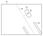
たとえば、図7の撮像装置1で撮像した画像71のように、制御対象としてエンドエフェクタ3である多指ハンド72、軸方向としてエンドエフェクタ3である多指ハンドの中心線74、目標位置として被把持部品73の中心位置75を用いてもよい。第1の実施形態と略同様に軸方向と目標位置との距離を近づけるように制御を行う。その後、エンドエフェクタ3である多指ハンドを前進し、閉じて、元の位置姿勢に戻ることで、被把持部品を正確に把持することができる。
For example, as in an
また別の例として、図8で制御対象の制御位置と目標の軸方向とを画像から検出する場合の説明をする(位置検出及び方向検出)。81は撮像装置1で撮像した画像、82はエンドエフェクタ3である多指ハンドで把持した制御対象である組付け部品を表す。83は制御対象である組付け部品の中心を検出した制御位置、84は被組付け部品、85は被組付け部品に基づいて検出した目標の軸方向を表す。第1の実施形態と略同様に軸方向と制御位置との距離を近づけるように制御を行う。その後、エンドエフェクタ3である多指ハンドを前進し、開いて、元の位置姿勢に戻ることで、制御対象に制御位置を設定し、被制御対象に軸方向を設定した場合でも正確にタスクを実行できる。なお、本実施形態において、把持は、把握(例えば複数のフィンガーで掴んだり挟持すること)や、保持(例えば真空吸着パッドや電磁力を利用して吸着すること)という概念を含む。
As another example, the case of detecting the control position of the controlled object and the axial direction of the target from the image will be described with reference to FIG. 8 (position detection and direction detection).
[第1の実施形態の変形例3]
図示しない動作表示部を用いて、ロボットの動作を表示してもよい。以下、図9を用いて動作表示部の一例を説明する。図9において、91はユーザに提示する動作表示部の画面、92は画像取得部101から受け取った画像、93は軸方向取得部102から受け取った軸方向を表している。94は目標位置検出部103から受け取った目標位置、95は軸が動く方向と距離、96は制御ループを一時的に停止する際に押す一時停止ボタンを表している。97は制御ループを1回実行する際に押すステップ実行ボタン、98は一時停止している制御ループを再開する際に押す再開ボタンを表している。ボタン操作は図示しないUI機器(たとえば、マウス)によって行う。図9において、95は矢印の方向が軸の動く方向、矢印の長さが軸の動く距離を示している。ただし、軸が動く距離は数値(実寸単位、画素単位)であっても構わない。また、軸が動く方向と距離とは、両方表示してあっても良いし、いずれか一方のみ表示してあっても良い。
[
A motion display section (not shown) may be used to display the motion of the robot. An example of the operation display unit will be described below with reference to FIG. In FIG. 9,
まず、動作表示部は、画像取得部101、軸方向取得部102および目標位置検出部103から画像データ、軸方向データおよび目標位置データを受け取り、軸方向および目標位置を画像に重畳して表示する。また、動作表示部は、動作生成部104から位置姿勢データを受け取り、制御対象が移動する方向および距離を重畳して表示する。次に、ユーザが一時停止ボタン96を押した場合、制御部106はロボットアーム2の制御を一時停止する。ユーザがステップ実行ボタン97を押した場合、制御部106はロボットの制御を再開し、次にステップS108に到達した後、再度ロボットの制御を一時停止する。最後に、ユーザが再開ボタン98を押すと、制御部106はロボットの制御を再開する。
First, the motion display unit receives image data, axial direction data, and target position data from the
このように、動作表示部を用いてロボットの動作を表示し、ロボットの動きを検出結果と共に確認しながら少しずつ動かすことで、制御や検出に必要なパラメータの調整や、問題が発生した時の原因解析を補助することができる。 In this way, the movement display unit is used to display the robot's movement, and by moving the robot little by little while confirming the detection result and the movement of the robot, it is possible to adjust the parameters necessary for control and detection, and to respond when a problem occurs. Can assist in root cause analysis.
[第1の実施形態の変形例4]
S101においてティーチングペンダントによる教示作業により設定した位置姿勢を取得したが、これに限る必要はない。たとえば、撮像装置1であるステレオカメラで俯瞰して撮像した画像に基づいて、ネジを検出しておおよその3次元位置を計測した結果に基づいて位置姿勢を求めてもよい。あるいは、CADデータのような3次元モデルを用いてシミュレータにより位置姿勢を設定してもよい。また、複数の目標位置をタスク実行する順番と共に設定してもよい。
[Modification 4 of the first embodiment]
Although the position and orientation set by the teaching operation using the teaching pendant are acquired in S101, the present invention is not limited to this. For example, the position and orientation may be obtained based on the result of detecting a screw and measuring its approximate three-dimensional position based on an image captured by a stereo camera, which is the imaging device 1 . Alternatively, the position and orientation may be set by a simulator using a three-dimensional model such as CAD data. Also, a plurality of target positions may be set together with the task execution order.
(第2の実施形態)
第2の実施形態では、第1の実施形態と同様に、ロボットに取り付けた撮像装置で、制御対象と目標位置とを撮像し、制御対象を目標位置まで誘導する。ただし、第2の実施形態では、光を投射する光投射装置と、光を投射した画像から目標であるネジが締結されている平面を計測する平面計測部とを備える点で第1の実施形態と異なる。目標であるネジが締結されている平面を計測することで、平面と軸方向とが決められた角度(例えば垂直)になるよう制御する作業を実現することができる。すなわち、目標位置における目標姿勢を求めることができる。このように目標位置と目標姿勢を求め、ロボットを制御することで、ロボットがエンドエフェクタであるドライバをネジに対して概略垂直に当ててネジを安定的に外すことができる。すなわち、ロボットによるタスクを安定的に行うことができる。
(Second embodiment)
In the second embodiment, as in the first embodiment, an imaging device attached to the robot images the controlled object and the target position, and guides the controlled object to the target position. However, the second embodiment differs from the first embodiment in that it includes a light projection device that projects light and a plane measurement unit that measures a target plane on which a screw is fastened from an image projected with light. different from By measuring the plane on which the target screw is fastened, it is possible to realize the work of controlling the plane and the axial direction to form a predetermined angle (for example, perpendicular). That is, the target posture at the target position can be obtained. By obtaining the target position and the target posture in this way and controlling the robot, the robot can stably remove the screw by applying the driver, which is an end effector, to the screw substantially perpendicularly. In other words, the task can be stably performed by the robot.
[装置の構成]
図10のブロック図により第2の実施形態の制御装置200を備えるロボットシステム2000の装置例を示す。ロボットシステム2000は、撮像装置1と、ロボットアーム2と、エンドエフェクタ3と、光投射装置4と、制御装置200とを備える。なお、撮像装置1、ロボットアーム2、エンドエフェクタ3は、第1の実施形態と略同様であるため、説明を省略する。
[Device configuration]
The block diagram of FIG. 10 shows an example of a
光投射装置4は、平面計測をする対象に特徴となる光を投射する装置である。たとえば、光投射装置4は、十字のラインレーザ光を投射するクロスラインレーザ投射機で構成され、制御部106から受け取った投射トリガによってレーザ光を投射する。
The light projection device 4 is a device for projecting characteristic light onto an object for planar measurement. For example, the light projection device 4 is configured by a cross-line laser projector that projects cross-shaped line laser light, and projects the laser light according to a projection trigger received from the
制御装置200は、画像取得部101と、軸方向取得部102と、目標位置検出部103と、平面計測部201と、動作生成部202と、終了判断部105と、制御部106とを備える。なお、画像取得部101、軸方向取得部102、目標位置検出部103、終了判断部105、制御部106は、第1の実施形態と略同様であるため、説明を省略する。
The
平面計測部201は、画像取得部101から、レーザ光が投射された画像データを受け取り、画像データから平面の3次元の法線を検出し、目標平面のデータ(法線データ)を動作生成部202に送る。
The
動作生成部202は、軸方向取得部102、目標位置検出部103および平面計測部201から受け取った軸方向データ、目標位置データおよび法線データに基づいて、ロボットアーム2の先端部の動作を規定する位置姿勢を計算する。そして、計算した位置姿勢データを制御部106に送る。
The
[制御処理]
図11のフローチャートにより第2の実施形態の制御装置200およびロボットシステム2000による制御処理方法を説明する。ステップS101~ステップS105、ステップS107~S111は、それぞれ第1の実施形態と略同様であるため、説明を省略する。
[Control processing]
A control processing method by the
(ステップS201)
ステップS201では、光投射装置4が、制御部106から投射トリガを受け取り、レーザ光を投射する。これにより、特徴のない平面でも安定して撮像装置1であるステレオカメラにより平面計測ができる。
(Step S201)
In step S201, the light projection device 4 receives a projection trigger from the
(ステップS202)
ステップS202では、撮像装置1が、制御部106から撮像トリガを受け取り、撮像を行い、撮像した画像信号を画像取得部101に送る。
(Step S202)
In step S<b>202 , the imaging device 1 receives an imaging trigger from the
(ステップS203)
ステップS203では、画像取得部101が、撮像装置1から画像信号を受け取り、平面計測部201に画像データを送る。
(Step S203)
In step S<b>203 , the
(ステップS204)
ステップS204では、平面計測部201が、画像取得部101から画像データを受け取り、画像データから平面の法線を検出し、法線データを動作生成部202に送る。法線の検出は、たとえば、撮像装置1であるステレオカメラの左右の画像に基づいて、ステレオマッチングにより画像に投射されたレーザ領域の3次元点群を計測する。平面計測部201が、計測した3次元点群を主成分分析した第3主成分を計算することで、平面の法線を検出する。
(Step S204)
In step S<b>204 , the
(ステップS205)
ステップS205では、動作生成部202が、軸方向取得部102、目標位置検出部103および平面計測部201から軸方向データ、目標位置データおよび法線データを受け取り、ロボットアーム2の先端部の動作を規定する位置姿勢を計算する。また、動作生成部202が位置姿勢データを制御部106に送る。
(Step S205)
In step S205, the
以下、動作生成の一例を説明する。本実施形態では、ネジが締結されている平面に対して、エンドエフェクタ3であるドライバの軸をおおよそ垂直に当てるように制御する。エンドエフェクタ座標系44をロボット座標系41で表すと、式8となる。
An example of motion generation will be described below. In this embodiment, the shaft of the driver, which is the

また、撮像装置座標系43で計測した平面姿勢Oをロボット座標系41で表すと、式9となる。
Further, when the planar orientation O measured by the imaging device coordinate

ドライバ軸を平面に対して垂直に当てるように制御するため、エンドエフェクタ座標系44の位置成分はそのままに、姿勢成分のz軸を平面の法線とおおよそ一致させる。平面の法線を目標姿勢として、姿勢成分のz軸方向が目標姿勢となるよう求めたドライバ位置姿勢を初期位置姿勢として第1の実施形態と略同様の動作生成を行う。
In order to control the driver axis so that it hits the plane perpendicularly, the position component of the end effector coordinate
このようにすることで、エンドエフェクタ3を前進させたときに、ネジが締結されている平面に対して、エンドエフェクタ3であるドライバの軸をおおよそ垂直に当てるように制御できる。なお、本実施形態では、平面計測部201が、S101の初期化後に1度だけ平面計測を行ったが、これに限る必要はない。平面計測部201が、S205である動作生成の直前に平面計測を行ってもよいし、平面計測部201および動作生成部202がS110であるタスク実行直前に平面計測および動作生成を再度行ってもよい。
In this way, when the
[効果]
本実施形態によれば、平面計測をすることで、制御対象に関連付けられた軸方向と平面との角度を制御するようビジュアルサーボを実行できる。その結果、目標位置における制御対象の姿勢が重要なタスクを実現できる。
[effect]
According to this embodiment, by performing plane measurement, visual servo can be executed to control the angle between the axial direction associated with the control target and the plane. As a result, a task in which the attitude of the controlled object at the target position is important can be realized.
[第2の実施形態の変形例1]
S204においてレーザ光が投影された画像を用いて平面計測を行ったが、これに限る必要はない。たとえば、平面にある模様を使ってもよいし、プロジェクタによってパターンを投影してもよいし、撮像装置1としてDepthカメラを用いてもよい。
[Modification 1 of Second Embodiment]
Although the plane measurement is performed using the image projected by the laser beam in S204, it is not necessary to limit to this. For example, a pattern on a plane may be used, a pattern may be projected by a projector, or a depth camera may be used as the imaging device 1 .
(第3の実施形態)
第3の実施形態では、第1の実施形態と同様に、ロボットに取り付けた撮像装置で、制御対象と目標位置とを撮像し、制御対象を目標位置まで誘導する。ただし、第3の実施形態では、誘導した結果をキャリブレーション値に反映する点で第1の実施形態と異なる。ここで、キャリブレーション値とは、撮像装置1とロボットアーム2とエンドエフェクタ3との位置姿勢関係を表すパラメータのことである。キャリブレーション値の誤差が大きいほどビジュアルサーボの動作収束に時間がかかるが、本実施形態の方法を用いることで素早く収束させることができる。
(Third embodiment)
In the third embodiment, as in the first embodiment, an imaging device attached to the robot images the controlled object and the target position, and guides the controlled object to the target position. However, the third embodiment differs from the first embodiment in that the derived result is reflected in the calibration value. Here, the calibration value is a parameter representing the position and orientation relationship among the imaging device 1 , the
[装置の構成]
図12のブロック図により第3の実施形態の制御装置300を備えるロボットシステム3000の装置例を示す。ロボットシステム3000は、撮像装置1と、ロボットアーム2と、エンドエフェクタ3と、制御装置300とを備える。なお、撮像装置1、ロボットアーム2、エンドエフェクタ3は、第1の実施形態と略同様であるため、説明を省略する。
[Device configuration]
The block diagram of FIG. 12 shows an example of a
制御装置300は、画像取得部101と、軸方向取得部102と、目標位置検出部103と、動作生成部301と、キャリブレーション値補正部302と、キャリブレーション値保存部303と、終了判断部105と、制御部106とを備える。なお、画像取得部101、軸方向取得部102、目標位置検出部103、終了判断部105、制御部106は、第1の実施形態と略同様であるため、説明を省略する。
The
動作生成部301は、軸方向取得部102、目標位置検出部103およびキャリブレーション値保存部303から受け取った軸方向データ、目標位置データおよびキャリブレーション値に基づいてロボットアーム2の先端部の動作を規定する位置姿勢を計算する。そして、位置姿勢データを制御部106およびキャリブレーション値補正部302に送る。
The
キャリブレーション値補正部302は、動作生成部301から位置姿勢データを受け取り、キャリブレーション値を補正し、補正したキャリブレーション値をキャリブレーション値保存部303に送る。
The calibration
キャリブレーション値保存部303は、キャリブレーション値補正部302からキャリブレーション値を受け取り、保存する。また、キャリブレーション値保存部303は、動作生成部301にキャリブレーション値を送る。たとえば、キャリブレーション値保存部303はメモリから構成される。
The calibration
[制御処理]
図13のフローチャートにより第3の実施形態の制御装置300およびロボットシステム3000による制御処理方法を説明する。ステップS101~ステップS105、ステップS107~S111は、それぞれ第1の実施形態と略同様であるため、説明を省略する。
[Control processing]
A control processing method by the
(ステップS301)
ステップS301では、動作生成部301が、軸方向取得部102、目標位置検出部103およびキャリブレーション値保存部303から軸方向データ、目標位置データおよびキャリブレーション値を受け取る。動作生成部301は受け取ったキャリブレーション値を用いて実施形態1と略同様にロボットアーム2の先端部の動作を規定する位置姿勢を計算する。また、動作生成部301が位置姿勢データを制御部106およびキャリブレーション値補正部302に送る。
(Step S301)
In step S<b>301 , the
(ステップS302)
ステップS302では、キャリブレーション値補正部302が、動作生成部301から動作生成部301により生成された結果(位置姿勢データ)を受け取り、キャリブレーション値の補正を行う。そして、補正したキャリブレーション値をキャリブレーション値保存部303に送る。ビジュアルサーボを実行している中でキャリブレーション値の補正を行うことで、徐々に誤差を低減していくことができる。補正するキャリブレーション値は、ロボットアーム2の先端部と撮像装置1であるカメラとの位置姿勢の関係性を表す変換行列G でもよいし、撮像装置1であるカメラとエンドエフェクタ3であるドライバとの位置姿勢の関係性を表す変換行列Hでもよい。本実施形態では、変換行列Gを補正する。補正後の変換行列をG'とすると、式5より式10が成り立つ。
(Step S302)
In step S302, the calibration

(ステップS303)
ステップS303では、キャリブレーション値保存部303が、キャリブレーション値補正部302から補正されたキャリブレーション値を受け取り保存する。
(Step S303)
In step S303, the calibration
[効果]
本実施形態によれば、制御対象を制御すると同時にキャリブレーション値を補正することで、キャリブレーション値の誤差を徐々に小さくできる。その結果、次のビジュアルサーボ実行時にはより素早く制御を終了することができる。
[effect]
According to this embodiment, by correcting the calibration value while controlling the controlled object, the error in the calibration value can be gradually reduced. As a result, the control can be finished more quickly when the next visual servo is executed.
[第3の実施形態の変形例1]
S303においてキャリブレーション値のみを保存したが、これに限る必要はない。たとえば、現在のロボット位置姿勢とキャリブレーション値との組を保存してもよいし、教示作業により設定した初期位置姿勢のIDとキャリブレーション値との組を保存してもよい。これにより、ロボットの位置姿勢に依存するようなキャリブレーション誤差が存在する場合でも、各位置姿勢において誤差を低減することができる。
[Modification 1 of the third embodiment]
Although only the calibration values are saved in S303, this need not be the case. For example, a set of the current robot position/orientation and calibration values may be saved, or a set of an initial position/orientation ID set by teaching work and calibration values may be saved. As a result, even if there is a calibration error that depends on the position and orientation of the robot, the error can be reduced for each position and orientation.
[ハードウェア構成]
図2、図10、図12に示した制御装置100、200、300は、一般のPC(パーソナルコンピュータ)を用いて実現することができる。制御装置100、200、300において各部の機能をPCのCPUに実行させるためのコンピュータプログラムやデータをハードディスク装置に格納しておく。CPUは、ハードディスク装置に格納されているコンピュータプログラムやデータを適宜RAM等のメモリにロードし、該コンピュータプログラムやデータを用いて処理を実行できる。これにより、結果としてPCは、制御装置100、200、300の機能を実現することができる。
[Hardware configuration]
The
[その他の変形例1]
すべての実施形態において、撮像装置1として2台のグレースケールカメラを用いたが、これに限る必要はない。3台以上のグレースケールカメラを用いてもよいし、RGBのカラーカメラを用いてもよいし、Depthカメラを用いてもよい。
[Other modification 1]
Although two grayscale cameras are used as the imaging device 1 in all the embodiments, it is not necessary to be limited to this. Three or more grayscale cameras, RGB color cameras, or depth cameras may be used.
[その他の変形例2]
すべての実施形態において、ロボットアーム2として6軸ロボットを用いたが、これに限る必要はない。その他の多関節ロボットやパラレルリンクロボットでもよいし、直交ロボットでもよい。
[Other modification 2]
Although a six-axis robot is used as the
[その他の変形例3]
第1の実施形態において、エンドエフェクタ3であるドライバとネジとの接触の検知に近接センサを用いたが、これに限る必要はない。画像に基づいて検知してもよいし、距離センサを用いてもよいし、力覚センサを用いてもよい。
[Other modification 3]
In the first embodiment, the proximity sensor is used to detect the contact between the driver, which is the
<実施形態の効果>
第1の実施形態によれば、画像中の軸方向および目標位置からビジュアルサーボによるロボット制御を実現することができる。その結果、キャリブレーション作業の負荷を低減しながら、画像から十分に特徴を抽出できない場合においても、高精度にタスクを実行できる。
<Effects of Embodiment>
According to the first embodiment, robot control by visual servo can be realized from the axial direction and the target position in the image. As a result, the task can be performed with high accuracy even when sufficient features cannot be extracted from the image while reducing the load of the calibration work.
第2の実施形態によれば、平面計測をすることで、制御対象に関連付けられた軸方向と平面との角度を制御するようビジュアルサーボを実行できる。その結果、目標位置における制御対象の姿勢が重要なタスクを実現できる。 According to the second embodiment, by performing a plane measurement, visual servoing can be performed to control the angle between the axial direction associated with the controlled object and the plane. As a result, a task in which the attitude of the controlled object at the target position is important can be realized.
第3の実施形態によれば、制御対象を制御すると同時にキャリブレーション値を補正することで、キャリブレーション値の誤差を徐々に小さくできる。その結果、次のビジュアルサーボ実行時にはより素早く制御を終了することができる。 According to the third embodiment, by correcting the calibration value while controlling the controlled object, the error in the calibration value can be gradually reduced. As a result, the control can be finished more quickly when the next visual servo is executed.
<定義>
目標位置とはエンドエフェクタがタスクを実行する位置のことである。軸方向とは、制御対象と目標位置との位置姿勢関係を測るための制御対象に関連付けられた画像中の線分のことである。タスク動作とは、ロボットアーム及びエンドエフェクタを、事前に設定された動きで制御することである。動作パラメータとは、制御対象の制御量の成分のことである。キャリブレーション値とは、撮像装置とロボットアームとエンドエフェクタとの位置姿勢関係を表すパラメータのことである。
<Definition>
A target position is the position at which the end effector performs a task. The axial direction is a line segment in the image associated with the controlled object for measuring the position and orientation relationship between the controlled object and the target position. A task motion is to control a robot arm and an end effector with a preset motion. An operating parameter is a component of a controlled variable to be controlled. A calibration value is a parameter representing the position/orientation relationship among an imaging device, a robot arm, and an end effector.
(その他の実施形態)
本発明は、上述の実施形態の1以上の機能を実現するプログラムを、ネットワーク又は記憶媒体を介してシステム又は装置に供給し、そのシステム又は装置のコンピュータにおける1つ以上のプロセッサがプログラムを読出し実行する処理でも実現可能である。また、1以上の機能を実現する回路(例えば、ASIC)によっても実現可能である。
(Other embodiments)
The present invention supplies a program that implements one or more functions of the above-described embodiments to a system or apparatus via a network or a storage medium, and one or more processors in the computer of the system or apparatus reads and executes the program. It can also be realized by processing to It can also be implemented by a circuit (for example, ASIC) that implements one or more functions.
1000:ロボットシステム、1:撮像装置、2:ロボットアーム、3:エンドエフェクタ、100:制御装置、101:画像取得部、102:軸方向取得部、103:目標位置検出部、104:動作生成部、105:終了判断部、106:制御部 1000: robot system, 1: imaging device, 2: robot arm, 3: end effector, 100: control device, 101: image acquisition unit, 102: axial direction acquisition unit, 103: target position detection unit, 104: motion generation unit , 105: end determination unit, 106: control unit
Claims (14)
前記画像における前記制御対象のエッジに基づいて、前記制御対象の回転軸の進行方向であって前記制御対象の回転軸に沿っている前記進行方向を表す該画像中の2次元方向を取得する進行方向取得手段と、
前記画像から前記目標位置を表す該画像中の2次元位置を検出する目標位置検出手段と、
前記回転軸の進行方向の延長上に前記目標位置が存在し、前記回転軸の進行方向と前記凹部の深さ方向とが一致するように前記制御対象の姿勢を変更する動作を前記制御対象が前記目標位置に達する前に生成し、さらに姿勢を変更した制御対象の進行方向に沿って前記制御対象を前記目標位置に近づける動作を生成する動作生成手段と、
前記動作に従って前記制御対象を制御する制御手段と、
を備え、
前記動作生成手段は、前記2次元方向に沿った線分と前記2次元位置とを近づける前記制御対象の姿勢の制御量を求め、該制御量に基づいて前記制御対象の姿勢を更新することを特徴とする制御装置。 An imaging device attached to a robot acquires an image of a controlled object whose rotation can be controlled by the robot and a target position, which is a destination of movement of the controlled object, and is a target position in a concave portion. an image acquisition means;
A progression for acquiring a two-dimensional direction in the image representing the traveling direction of the rotational axis of the controlled object and along the rotational axis of the controlled object, based on the edges of the controlled object in the image. a direction acquisition means;
target position detection means for detecting a two-dimensional position in the image representing the target position from the image ;
The target position exists on the extension of the traveling direction of the rotating shaft, and the controlled object performs an operation of changing the attitude of the controlled object so that the traveling direction of the rotating shaft and the depth direction of the recess match. a motion generation means for generating a motion of moving the controlled object closer to the target position along the traveling direction of the controlled object whose attitude has been changed, which is generated before reaching the target position;
a control means for controlling the controlled object according to the operation;
with
The motion generating means obtains a control amount of the posture of the control object that brings the line segment along the two-dimensional direction closer to the two-dimensional position, and updates the posture of the control object based on the control amount. A control device characterized by:
前記動作生成手段は、前記目標平面に基づいて、前記凹部の深さ方向を求めることを特徴とする請求項1に記載の制御装置。 Further comprising plane measurement means for measuring the target plane,
2. The control device according to claim 1, wherein the motion generating means obtains the depth direction of the concave portion based on the target plane.
前記キャリブレーション値および前記動作生成手段により生成された結果に基づいて、前記キャリブレーション値を補正するキャリブレーション値補正手段と、
をさらに備えることを特徴とする請求項1に記載の制御装置。 calibration value storage means for storing a calibration value, which is a parameter representing a position and orientation relationship between the imaging device, a robot arm of the robot, and the controlled object;
calibration value correcting means for correcting the calibration value based on the calibration value and the result generated by the action generating means;
2. The controller of claim 1, further comprising: a.
前記画像から前記制御対象に関連付けられた制御位置を表す該画像中の2次元位置を検出する位置検出手段と、
前記画像における前記制御対象のエッジに基づいて、前記目標に関連付けられた前記制御対象の回転軸に沿った進行方向を表す該画像中の2次元方向を検出する方向検出手段と、
前記回転軸の進行方向及び前記制御位置に基づいて、前記回転軸の進行方向と前記凹部の深さ方向とが一致するように前記制御対象の姿勢を変更する動作を前記制御対象が目標位置に達する前に生成し、さらに姿勢を変更した制御対象の回転軸の進行方向に沿って前記制御対象を前記制御位置に近付ける動作を生成する動作生成手段と、
前記動作に従って前記制御対象を制御する制御手段と、
を備え、
前記動作生成手段は、前記2次元方向に沿った線分と前記2次元位置とを近づける前記制御対象の姿勢の制御量を求め、該制御量に基づいて前記制御対象の姿勢を更新することを特徴とする制御装置。 an image acquisition means for acquiring an image of a controlled object whose rotation can be controlled by the robot and a target, which is a destination of movement of the controlled object and which is located in a concave portion, by an imaging device attached to the robot;
position detection means for detecting from the image a two-dimensional position in the image representing a control position associated with the control object;
direction detection means for detecting a two-dimensional direction in the image representing a direction of travel along an axis of rotation of the controlled object associated with the target, based on edges of the controlled object in the image;
The controlled object moves to a target position by changing the attitude of the controlled object so that the advancing direction of the rotating shaft and the depth direction of the concave portion are aligned based on the advancing direction of the rotating shaft and the control position. a motion generating means for generating a motion for bringing the controlled object closer to the control position along the advancing direction of the rotation axis of the controlled object whose attitude has been changed;
a control means for controlling the controlled object according to the operation;
with
The motion generating means obtains a control amount of the posture of the control object that brings the line segment along the two-dimensional direction closer to the two-dimensional position, and updates the posture of the control object based on the control amount. A control device characterized by:
前記画像における前記制御対象のエッジに基づいて、前記制御対象の回転軸の進行方向であって前記制御対象の回転軸に沿っている前記進行方向を表す該画像中の2次元方向を取得する進行方向取得手段と、
前記画像から前記目標位置を表す該画像中の2次元位置を検出する目標位置検出手段と、
前記回転軸の進行方向の延長上に前記目標位置が存在し、前記回転軸の進行方向と前記凹部の深さ方向とが一致するように前記制御対象の姿勢を変更する動作を前記制御対象が前記目標位置に達する前に生成し、さらに姿勢を変更した制御対象の進行方向に沿って前記制御対象を前記目標位置に近づける動作を生成する動作生成手段と、
前記動作に従って前記制御対象を制御する制御手段と、
を備え、
前記動作生成手段は、前記2次元方向に沿った線分と前記2次元位置とを近づける前記制御対象の姿勢の制御量を求め、該制御量に基づいて前記制御対象の姿勢を更新する制御装置と、
前記ロボットと、
前記撮像装置と、
を備えることを特徴とするロボットシステム。 An imaging device attached to a robot acquires an image of a controlled object whose rotation can be controlled by the robot and a target position, which is a destination of movement of the controlled object, and is a target position in a concave portion. an image acquisition means;
A progression for acquiring a two-dimensional direction in the image representing the traveling direction of the rotational axis of the controlled object and along the rotational axis of the controlled object, based on the edges of the controlled object in the image. a direction acquisition means;
target position detection means for detecting a two-dimensional position in the image representing the target position from the image ;
The target position exists on the extension of the traveling direction of the rotating shaft, and the controlled object performs an operation of changing the attitude of the controlled object so that the traveling direction of the rotating shaft and the depth direction of the recess match. a motion generation means for generating a motion of moving the controlled object closer to the target position along the traveling direction of the controlled object whose attitude has been changed, which is generated before reaching the target position;
a control means for controlling the controlled object according to the operation;
with
The motion generating means obtains a control amount of the attitude of the controlled object that brings the line segment along the two-dimensional direction closer to the two-dimensional position, and performs control for updating the attitude of the controlled object based on the control amount. a device;
the robot;
the imaging device;
A robot system comprising:
ロボットに取り付けられた撮像装置により、前記ロボットが回転制御可能な制御対象及び前記制御対象の移動先である目標位置であって凹部にある目標の位置である前記目標位置を撮像した画像を取得する工程と、
前記画像における前記制御対象のエッジに基づいて、前記制御対象の回転軸の進行方向であって前記制御対象の回転軸に沿っている前記進行方向を表す該画像中の2次元方向を取得する工程と、
前記画像から前記目標位置を表す該画像中の2次元位置を検出する工程と、
前記回転軸の進行方向の延長上に前記目標位置が存在し、前記回転軸の進行方向と前記凹部の深さ方向とが一致するように前記制御対象の姿勢を変更する動作を前記制御対象が前記目標位置に達する前に生成し、さらに姿勢を変更した制御対象の進行方向に沿って前記制御対象を前記目標位置に近づける動作を生成する工程と、
前記動作に従って前記制御対象を制御する工程と、
を有し、
前記動作を生成する工程では、前記2次元方向に沿った線分と前記2次元位置とを近づける前記制御対象の姿勢の制御量を求め、該制御量に基づいて前記制御対象の姿勢を更新することを特徴とする制御装置の動作方法。 A method of operating a controller, comprising:
An imaging device attached to a robot acquires an image of a controlled object whose rotation can be controlled by the robot and a target position, which is a destination of movement of the controlled object, and is a target position in a concave portion. process and
obtaining a two-dimensional direction in the image representing the direction of travel of the axis of rotation of the controlled object and along the axis of rotation of the controlled object, based on the edges of the controlled object in the image; and,
detecting from the image a two-dimensional position in the image representing the target position;
The target position exists on the extension of the traveling direction of the rotating shaft, and the controlled object performs an operation of changing the attitude of the controlled object so that the traveling direction of the rotating shaft and the depth direction of the recess match. a step of generating a motion for bringing the controlled object closer to the target position along a traveling direction of the controlled object generated before reaching the target position and having a changed attitude;
a step of controlling the controlled object according to the operation;
has
In the step of generating the motion, a control amount of the attitude of the controlled object that brings the line segment along the two-dimensional direction closer to the two-dimensional position is obtained, and the attitude of the controlled object is updated based on the control amount. A method of operating a control device, characterized by:
ロボットに取り付けられた撮像装置により、前記ロボットが回転制御可能な制御対象及び前記制御対象の移動先である目標であって凹部にある前記目標を撮像した画像を取得する工程と、
前記画像から前記制御対象に関連付けられた制御位置を表す該画像中の2次元位置を検出する工程と、
前記画像における前記制御対象のエッジに基づいて、前記目標に関連付けられた前記制御対象の回転軸に沿った進行方向を表す該画像中の2次元方向を検出する工程と、
前記回転軸の進行方向及び前記制御位置に基づいて、前記回転軸の進行方向と前記凹部の深さ方向とが一致するように前記制御対象の姿勢を変更する動作を前記制御対象が目標位置に達する前に生成し、さらに姿勢を変更した制御対象の回転軸の進行方向に沿って前記制御対象を前記制御位置に近付ける動作を生成する工程と、
前記動作に従って前記制御対象を制御する工程と、
を有し、
前記動作を生成する工程では、前記2次元方向に沿った線分と前記2次元位置とを近づける前記制御対象の姿勢の制御量を求め、該制御量に基づいて前記制御対象の姿勢を更新することを特徴とする制御装置の動作方法。 A method of operating a controller, comprising:
obtaining an image of a controlled object whose rotation can be controlled by the robot and a target to which the controlled object moves and which is located in a concave portion, by an imaging device attached to the robot;
detecting from the image a two-dimensional position in the image representing a control position associated with the controlled object;
Detecting a two-dimensional direction in the image representing a direction of travel along an axis of rotation of the controlled object associated with the target based on edges of the controlled object in the image;
The controlled object moves to a target position by changing the attitude of the controlled object so that the advancing direction of the rotating shaft and the depth direction of the concave portion are aligned based on the advancing direction of the rotating shaft and the control position. a step of generating a motion for bringing the controlled object closer to the control position along the advancing direction of the rotation axis of the controlled object generated before reaching and further changing the attitude;
a step of controlling the controlled object according to the operation;
has
In the step of generating the motion, a control amount of the attitude of the controlled object that brings the line segment along the two-dimensional direction closer to the two-dimensional position is obtained, and the attitude of the controlled object is updated based on the control amount. A method of operating a control device, characterized by:
ロボットに取り付けられた撮像装置により、前記ロボットが回転制御可能な制御対象及び前記制御対象の移動先である目標位置であって凹部にある目標の位置である前記目標位置を撮像した画像を取得する工程と、
前記画像における前記制御対象のエッジに基づいて、前記制御対象の回転軸の進行方向であって前記制御対象の回転軸に沿っている前記進行方向を表す該画像中の2次元方向を取得する工程と、
前記画像から前記目標位置を表す該画像中の2次元位置を検出する工程と、
前記回転軸の進行方向の延長上に前記目標位置が存在し、前記回転軸の進行方向と前記凹部の深さ方向とが一致するように前記制御対象の姿勢を変更する動作を前記制御対象が前記目標位置に達する前に生成し、さらに姿勢を変更した制御対象の進行方向に沿って前記制御対象を前記目標位置に近づける動作を生成する工程と、
前記動作に従って前記制御対象を制御する工程と、
を有し、
前記動作を生成する工程では、前記2次元方向に沿った線分と前記2次元位置とを近づける前記制御対象の姿勢の制御量を求め、該制御量に基づいて前記制御対象の姿勢を更新する制御装置の動作方法を、コンピュータに実行させるためのプログラム。 A method of operating a controller, comprising:
An imaging device attached to a robot acquires an image of a controlled object whose rotation can be controlled by the robot and a target position, which is a destination of movement of the controlled object, and is a target position in a concave portion. process and
obtaining a two-dimensional direction in the image representing the direction of travel of the axis of rotation of the controlled object and along the axis of rotation of the controlled object, based on the edges of the controlled object in the image; and,
detecting from the image a two-dimensional position in the image representing the target position;
The target position exists on the extension of the traveling direction of the rotating shaft, and the controlled object performs an operation of changing the attitude of the controlled object so that the traveling direction of the rotating shaft and the depth direction of the recess match. a step of generating a motion for bringing the controlled object closer to the target position along a traveling direction of the controlled object generated before reaching the target position and having a changed attitude;
a step of controlling the controlled object according to the operation;
has
In the step of generating the motion, a control amount of the attitude of the controlled object that brings the line segment along the two-dimensional direction closer to the two-dimensional position is obtained, and the attitude of the controlled object is updated based on the control amount. A program that causes a computer to execute the operation method of the control device.
ロボットに取り付けられた撮像装置により、前記ロボットが回転制御可能な制御対象及び前記制御対象の移動先である目標であって凹部にある前記目標を撮像した画像を取得する工程と、
前記画像から前記制御対象に関連付けられた制御位置を表す該画像中の2次元位置を検出する工程と、
前記画像における前記制御対象のエッジに基づいて、前記目標に関連付けられた前記制御対象の回転軸に沿った進行方向を表す該画像中の2次元方向を検出する工程と、
前記回転軸の進行方向及び前記制御位置に基づいて、前記回転軸の進行方向と前記凹部の深さ方向とが一致するように前記制御対象の姿勢を変更する動作を前記制御対象が目標位置に達する前に生成し、さらに姿勢を変更した制御対象の回転軸の進行方向に沿って前記制御対象を前記制御位置に近付ける動作を生成する工程と、
前記動作に従って前記制御対象を制御する工程と、
を有し、
前記動作を生成する工程では、前記2次元方向に沿った線分と前記2次元位置とを近づける前記制御対象の姿勢の制御量を求め、該制御量に基づいて前記制御対象の姿勢を更新する制御装置の動作方法を、コンピュータに実行させるためのプログラム。 A method of operating a controller, comprising:
obtaining an image of a controlled object whose rotation can be controlled by the robot and a target to which the controlled object moves and which is located in a concave portion, by an imaging device attached to the robot;
detecting from the image a two-dimensional position in the image representing a control position associated with the controlled object;
Detecting a two-dimensional direction in the image representing a direction of travel along an axis of rotation of the controlled object associated with the target based on edges of the controlled object in the image;
The controlled object moves to a target position by changing the attitude of the controlled object so that the advancing direction of the rotating shaft and the depth direction of the concave portion are aligned based on the advancing direction of the rotating shaft and the control position. a step of generating a motion for bringing the controlled object closer to the control position along the advancing direction of the rotation axis of the controlled object generated before reaching and further changing the attitude;
a step of controlling the controlled object according to the operation;
has
In the step of generating the motion, a control amount of the attitude of the controlled object that brings the line segment along the two-dimensional direction closer to the two-dimensional position is obtained, and the attitude of the controlled object is updated based on the control amount. A program that causes a computer to execute the operation method of the control device.
Priority Applications (1)
| Application Number | Priority Date | Filing Date | Title |
|---|---|---|---|
| US16/163,745 US11358290B2 (en) | 2017-10-19 | 2018-10-18 | Control apparatus, robot system, method for operating control apparatus, and storage medium |
Applications Claiming Priority (2)
| Application Number | Priority Date | Filing Date | Title |
|---|---|---|---|
| JP2017202858 | 2017-10-19 | ||
| JP2017202858 | 2017-10-19 |
Publications (3)
| Publication Number | Publication Date |
|---|---|
| JP2019077026A JP2019077026A (en) | 2019-05-23 |
| JP2019077026A5 JP2019077026A5 (en) | 2021-11-04 |
| JP7323993B2 true JP7323993B2 (en) | 2023-08-09 |
Family
ID=66627183
Family Applications (1)
| Application Number | Title | Priority Date | Filing Date |
|---|---|---|---|
| JP2018182701A Active JP7323993B2 (en) | 2017-10-19 | 2018-09-27 | Control device, robot system, operating method and program for control device |
Country Status (1)
| Country | Link |
|---|---|
| JP (1) | JP7323993B2 (en) |
Families Citing this family (3)
| Publication number | Priority date | Publication date | Assignee | Title |
|---|---|---|---|---|
| CN110253586A (en) * | 2019-07-12 | 2019-09-20 | 珠海优特电力科技股份有限公司 | Electrical anti-error operates device and method |
| US20230089195A1 (en) * | 2020-03-31 | 2023-03-23 | Nec Corporation | Control device, control system, control method, and recording medium with control program recorded thereon |
| CN116348257A (en) * | 2020-10-30 | 2023-06-27 | 松下知识产权经营株式会社 | Robot control method |
Citations (10)
| Publication number | Priority date | Publication date | Assignee | Title |
|---|---|---|---|---|
| JP2006331255A (en) | 2005-05-30 | 2006-12-07 | Daihen Corp | Control method for industrial robot |
| JP2009285778A (en) | 2008-05-29 | 2009-12-10 | Toyota Industries Corp | Posture detecting system of robot hand |
| WO2011001569A1 (en) | 2009-07-02 | 2011-01-06 | パナソニック株式会社 | Robot, control device for robot arm, and control program for robot arm |
| JP2014161950A (en) | 2013-02-25 | 2014-09-08 | Dainippon Screen Mfg Co Ltd | Robot system, robot control method, and robot calibration method |
| JP2015000454A (en) | 2013-06-17 | 2015-01-05 | キヤノン株式会社 | Robot device and robot control method |
| JP2015112688A (en) | 2013-12-12 | 2015-06-22 | 株式会社Ihi | Robot remote control system and robot remote control method |
| JP2016000442A (en) | 2014-06-12 | 2016-01-07 | セイコーエプソン株式会社 | Robot, robotic system, and control device |
| US20160243704A1 (en) | 2013-10-25 | 2016-08-25 | Aleksandar Vakanski | Image-based trajectory robot programming planning approach |
| JP2016159406A (en) | 2015-03-03 | 2016-09-05 | キヤノン株式会社 | Robot control device, robot control method and robot system |
| US20170154219A1 (en) | 2014-06-17 | 2017-06-01 | Yujin Robot Co., Ltd. | Apparatus of recognizing position of mobile robot using direct tracking and method thereof |
Family Cites Families (2)
| Publication number | Priority date | Publication date | Assignee | Title |
|---|---|---|---|---|
| JPS61279481A (en) * | 1985-06-01 | 1986-12-10 | 株式会社安川電機 | Method of detecting and controlling starting point of operation of robot |
| JP3998741B2 (en) * | 1995-07-12 | 2007-10-31 | ファナック株式会社 | Robot movement control method |
-
2018
- 2018-09-27 JP JP2018182701A patent/JP7323993B2/en active Active
Patent Citations (10)
| Publication number | Priority date | Publication date | Assignee | Title |
|---|---|---|---|---|
| JP2006331255A (en) | 2005-05-30 | 2006-12-07 | Daihen Corp | Control method for industrial robot |
| JP2009285778A (en) | 2008-05-29 | 2009-12-10 | Toyota Industries Corp | Posture detecting system of robot hand |
| WO2011001569A1 (en) | 2009-07-02 | 2011-01-06 | パナソニック株式会社 | Robot, control device for robot arm, and control program for robot arm |
| JP2014161950A (en) | 2013-02-25 | 2014-09-08 | Dainippon Screen Mfg Co Ltd | Robot system, robot control method, and robot calibration method |
| JP2015000454A (en) | 2013-06-17 | 2015-01-05 | キヤノン株式会社 | Robot device and robot control method |
| US20160243704A1 (en) | 2013-10-25 | 2016-08-25 | Aleksandar Vakanski | Image-based trajectory robot programming planning approach |
| JP2015112688A (en) | 2013-12-12 | 2015-06-22 | 株式会社Ihi | Robot remote control system and robot remote control method |
| JP2016000442A (en) | 2014-06-12 | 2016-01-07 | セイコーエプソン株式会社 | Robot, robotic system, and control device |
| US20170154219A1 (en) | 2014-06-17 | 2017-06-01 | Yujin Robot Co., Ltd. | Apparatus of recognizing position of mobile robot using direct tracking and method thereof |
| JP2016159406A (en) | 2015-03-03 | 2016-09-05 | キヤノン株式会社 | Robot control device, robot control method and robot system |
Also Published As
| Publication number | Publication date |
|---|---|
| JP2019077026A (en) | 2019-05-23 |
Similar Documents
| Publication | Publication Date | Title |
|---|---|---|
| CN111482959B (en) | Automatic hand-eye calibration system and method of robot motion vision system | |
| TWI672206B (en) | Method and apparatus of non-contact tool center point calibration for a mechanical arm, and a mechanical arm system with said calibration function | |
| JP5471355B2 (en) | 3D visual sensor | |
| US11358290B2 (en) | Control apparatus, robot system, method for operating control apparatus, and storage medium | |
| JP5850962B2 (en) | Robot system using visual feedback | |
| EP3392002A1 (en) | Information processing apparatus, measuring apparatus, system, interference determination method, and article manufacturing method | |
| JP6188440B2 (en) | Robot apparatus and robot control method | |
| JP5606241B2 (en) | Visual cognitive system and method for humanoid robot | |
| JP5949242B2 (en) | Robot system, robot, robot control apparatus, robot control method, and robot control program | |
| JP6180086B2 (en) | Information processing apparatus and information processing method | |
| JP7323993B2 (en) | Control device, robot system, operating method and program for control device | |
| JP4844453B2 (en) | Robot teaching apparatus and teaching method | |
| EP3272473B1 (en) | Teaching device and method for generating control information | |
| JP6700726B2 (en) | Robot controller, robot control method, robot control system, and computer program | |
| JP7111114B2 (en) | Information processing device, information processing method, and information processing system | |
| US20150202776A1 (en) | Data generation device for vision sensor and detection simulation system | |
| US10279473B2 (en) | Image processing device, image processing method, and computer program | |
| JP2014144516A (en) | Robot control device, robot system, robot, control method and program | |
| WO2022092168A1 (en) | Robot control device, and robot system | |
| WO2016151667A1 (en) | Teaching device and method for generating control information | |
| CN117794704A (en) | Robot control device, robot control system, and robot control method | |
| JP2616225B2 (en) | Relative positioning method | |
| CN115397634A (en) | Device for acquiring position of visual sensor in robot control coordinate system, robot system, method, and computer program | |
| WO2023013739A1 (en) | Robot control device, robot control system, and robot control method | |
| WO2023013698A1 (en) | Robot control device, robot control system, and robot control method |
Legal Events
| Date | Code | Title | Description |
|---|---|---|---|
| RD01 | Notification of change of attorney |
Free format text: JAPANESE INTERMEDIATE CODE: A7421 Effective date: 20210103 |
|
| A521 | Request for written amendment filed |
Free format text: JAPANESE INTERMEDIATE CODE: A523 Effective date: 20210113 |
|
| A521 | Request for written amendment filed |
Free format text: JAPANESE INTERMEDIATE CODE: A523 Effective date: 20210927 |
|
| A621 | Written request for application examination |
Free format text: JAPANESE INTERMEDIATE CODE: A621 Effective date: 20210927 |
|
| A977 | Report on retrieval |
Free format text: JAPANESE INTERMEDIATE CODE: A971007 Effective date: 20220711 |
|
| A131 | Notification of reasons for refusal |
Free format text: JAPANESE INTERMEDIATE CODE: A131 Effective date: 20220729 |
|
| A601 | Written request for extension of time |
Free format text: JAPANESE INTERMEDIATE CODE: A601 Effective date: 20220927 |
|
| A521 | Request for written amendment filed |
Free format text: JAPANESE INTERMEDIATE CODE: A523 Effective date: 20221128 |
|
| A131 | Notification of reasons for refusal |
Free format text: JAPANESE INTERMEDIATE CODE: A131 Effective date: 20230224 |
|
| A521 | Request for written amendment filed |
Free format text: JAPANESE INTERMEDIATE CODE: A523 Effective date: 20230421 |
|
| TRDD | Decision of grant or rejection written | ||
| A01 | Written decision to grant a patent or to grant a registration (utility model) |
Free format text: JAPANESE INTERMEDIATE CODE: A01 Effective date: 20230630 |
|
| A61 | First payment of annual fees (during grant procedure) |
Free format text: JAPANESE INTERMEDIATE CODE: A61 Effective date: 20230728 |
|
| R151 | Written notification of patent or utility model registration |
Ref document number: 7323993 Country of ref document: JP Free format text: JAPANESE INTERMEDIATE CODE: R151 |