JP6317618B2 - Information processing apparatus and method, measuring apparatus, and working apparatus - Google Patents
Information processing apparatus and method, measuring apparatus, and working apparatus Download PDFInfo
- Publication number
- JP6317618B2 JP6317618B2 JP2014094873A JP2014094873A JP6317618B2 JP 6317618 B2 JP6317618 B2 JP 6317618B2 JP 2014094873 A JP2014094873 A JP 2014094873A JP 2014094873 A JP2014094873 A JP 2014094873A JP 6317618 B2 JP6317618 B2 JP 6317618B2
- Authority
- JP
- Japan
- Prior art keywords
- information
- image
- orientation
- distance
- degree
- Prior art date
- Legal status (The legal status is an assumption and is not a legal conclusion. Google has not performed a legal analysis and makes no representation as to the accuracy of the status listed.)
- Expired - Fee Related
Links
Images
Classifications
-
- B—PERFORMING OPERATIONS; TRANSPORTING
- B25—HAND TOOLS; PORTABLE POWER-DRIVEN TOOLS; MANIPULATORS
- B25J—MANIPULATORS; CHAMBERS PROVIDED WITH MANIPULATION DEVICES
- B25J9/00—Program-controlled manipulators
- B25J9/16—Program controls
- B25J9/1694—Program controls characterised by use of sensors other than normal servo-feedback from position, speed or acceleration sensors, perception control, multi-sensor controlled systems, sensor fusion
- B25J9/1697—Vision controlled systems
-
- B—PERFORMING OPERATIONS; TRANSPORTING
- B25—HAND TOOLS; PORTABLE POWER-DRIVEN TOOLS; MANIPULATORS
- B25J—MANIPULATORS; CHAMBERS PROVIDED WITH MANIPULATION DEVICES
- B25J9/00—Program-controlled manipulators
- B25J9/16—Program controls
- B25J9/1656—Program controls characterised by programming, planning systems for manipulators
- B25J9/1669—Program controls characterised by programming, planning systems for manipulators characterised by special application, e.g. multi-arm co-operation, assembly, grasping
-
- G—PHYSICS
- G06—COMPUTING OR CALCULATING; COUNTING
- G06T—IMAGE DATA PROCESSING OR GENERATION, IN GENERAL
- G06T5/00—Image enhancement or restoration
- G06T5/73—Deblurring; Sharpening
-
- G—PHYSICS
- G06—COMPUTING OR CALCULATING; COUNTING
- G06T—IMAGE DATA PROCESSING OR GENERATION, IN GENERAL
- G06T7/00—Image analysis
- G06T7/70—Determining position or orientation of objects or cameras
- G06T7/73—Determining position or orientation of objects or cameras using feature-based methods
- G06T7/75—Determining position or orientation of objects or cameras using feature-based methods involving models
-
- G—PHYSICS
- G05—CONTROLLING; REGULATING
- G05B—CONTROL OR REGULATING SYSTEMS IN GENERAL; FUNCTIONAL ELEMENTS OF SUCH SYSTEMS; MONITORING OR TESTING ARRANGEMENTS FOR SUCH SYSTEMS OR ELEMENTS
- G05B2219/00—Program-control systems
- G05B2219/30—Nc systems
- G05B2219/40—Robotics, robotics mapping to robotics vision
- G05B2219/40564—Recognize shape, contour of object, extract position and orientation
-
- G—PHYSICS
- G05—CONTROLLING; REGULATING
- G05B—CONTROL OR REGULATING SYSTEMS IN GENERAL; FUNCTIONAL ELEMENTS OF SUCH SYSTEMS; MONITORING OR TESTING ARRANGEMENTS FOR SUCH SYSTEMS OR ELEMENTS
- G05B2219/00—Program-control systems
- G05B2219/30—Nc systems
- G05B2219/40—Robotics, robotics mapping to robotics vision
- G05B2219/40622—Detect orientation of workpiece during movement of end effector
-
- G—PHYSICS
- G06—COMPUTING OR CALCULATING; COUNTING
- G06T—IMAGE DATA PROCESSING OR GENERATION, IN GENERAL
- G06T2207/00—Indexing scheme for image analysis or image enhancement
- G06T2207/10—Image acquisition modality
- G06T2207/10004—Still image; Photographic image
-
- G—PHYSICS
- G06—COMPUTING OR CALCULATING; COUNTING
- G06T—IMAGE DATA PROCESSING OR GENERATION, IN GENERAL
- G06T2207/00—Indexing scheme for image analysis or image enhancement
- G06T2207/10—Image acquisition modality
- G06T2207/10028—Range image; Depth image; 3D point clouds
-
- G—PHYSICS
- G06—COMPUTING OR CALCULATING; COUNTING
- G06T—IMAGE DATA PROCESSING OR GENERATION, IN GENERAL
- G06T2207/00—Indexing scheme for image analysis or image enhancement
- G06T2207/20—Special algorithmic details
- G06T2207/20172—Image enhancement details
- G06T2207/20201—Motion blur correction
-
- G—PHYSICS
- G06—COMPUTING OR CALCULATING; COUNTING
- G06T—IMAGE DATA PROCESSING OR GENERATION, IN GENERAL
- G06T2207/00—Indexing scheme for image analysis or image enhancement
- G06T2207/30—Subject of image; Context of image processing
- G06T2207/30108—Industrial image inspection
- G06T2207/30164—Workpiece; Machine component
Landscapes
- Engineering & Computer Science (AREA)
- Robotics (AREA)
- Mechanical Engineering (AREA)
- Physics & Mathematics (AREA)
- General Physics & Mathematics (AREA)
- Theoretical Computer Science (AREA)
- Computer Vision & Pattern Recognition (AREA)
- Length Measuring Devices By Optical Means (AREA)
- Length Measuring Devices With Unspecified Measuring Means (AREA)
- Image Analysis (AREA)
Description
本発明は、物体の位置姿勢を計測する情報処理に関する。 The present invention relates to information processing for measuring the position and orientation of an object.
ロボット技術の発展に伴い、工業製品の組立のような、従来人間が行っていた複雑なタスクをロボットが代行する場面が増えた。ロボットは、ハンドなどのエンドエフェクタによって部品を把持して組立を行う。この組立において、把持対象の部品とロボット(ハンド)の間の相対的な位置姿勢を計測する必要がある。 Along with the development of robot technology, the number of scenes where robots act on behalf of complex tasks that have been performed by humans, such as assembly of industrial products, has increased. The robot performs assembly by gripping a part with an end effector such as a hand. In this assembly, it is necessary to measure the relative position and orientation between the part to be grasped and the robot (hand).
位置姿勢の計測方法として、カメラが撮影した二次元画像から検出される特徴や、距離センサが計測した距離データに対して、物体の三次元形状モデルを当て嵌めるモデルフィッティングがある。 As a method for measuring the position and orientation, there is model fitting in which a three-dimensional shape model of an object is fitted to features detected from a two-dimensional image captured by a camera and distance data measured by a distance sensor.
二次元画像に対するモデルフィッティングにおいては、物体の位置姿勢に基づき三次元形状モデルを画像上に投影した場合の投影像が、検出された特徴に当て嵌まるように位置姿勢を計測する。距離データに対するモデルフィッティングにおいては、距離データを表現する距離画像の各点を三次元座標をもつ三次元点群に変換し、三次元空間において三次元形状モデルが三次元点群に当て嵌まるように位置姿勢を計測する。 In model fitting for a two-dimensional image, the position and orientation are measured so that a projected image when a three-dimensional shape model is projected on the image based on the position and orientation of the object fits the detected feature. In model fitting for distance data, each point of the distance image representing the distance data is converted into a 3D point cloud with 3D coordinates so that the 3D shape model fits the 3D point cloud in the 3D space. Measure position and orientation.
二次元画像から得られる計測情報と、距離データから得られる計測情報を併用すれば、物体の位置姿勢をより高精度に計測することができる。 If the measurement information obtained from the two-dimensional image and the measurement information obtained from the distance data are used in combination, the position and orientation of the object can be measured with higher accuracy.
特許文献1は、二次元画像から得られる計測情報を利用する位置姿勢の計測方法、距離データから得られる計測情報を利用する位置姿勢の計測方法、それら位置姿勢の計測方法を併用する方法の一つを、計測対象の物体(以下、対象物)の形状に応じて選択する。そして、選択した方法によって対象物の位置姿勢を計測する方法を記載する。特許文献1の方法によれば、対象物の形状に最適な方法により計測が行われるため、高精度かつ高速な計測が可能になる。 Patent Document 1 describes a position and orientation measurement method that uses measurement information obtained from a two-dimensional image, a position and orientation measurement method that uses measurement information obtained from distance data, and a method that uses these position and orientation measurement methods in combination. Is selected according to the shape of the object to be measured (hereinafter referred to as the object). A method for measuring the position and orientation of the object by the selected method is described. According to the method of Patent Document 1, measurement is performed by a method that is optimal for the shape of the object, so that high-precision and high-speed measurement is possible.
しかし、撮像装置が移動しながら対象物を撮影する場合、モーションブラーの影響により位置姿勢の推定精度が低下する。モーションブラーの影響は、形状情報のみでは推定することが困難である。このため、形状情報から観測情報を選択して位置姿勢を計測する特許文献1の方法は、撮像装置が移動しながら対象物を撮影する場合、対象物の位置姿勢を高精度に計測することができない。 However, when the imaging apparatus moves and captures an object, the estimation accuracy of the position and orientation decreases due to the influence of motion blur. It is difficult to estimate the effect of motion blur only with shape information. For this reason, the method of Patent Document 1 that selects the observation information from the shape information and measures the position and orientation can measure the position and orientation of the object with high accuracy when imaging the object while the imaging apparatus moves. Can not.
本発明は、移動中に対象物を撮影する状況においても、対象物の位置姿勢の計測を高精度に行うことを目的とする。 An object of the present invention is to measure the position and orientation of an object with high accuracy even in a situation where the object is photographed during movement.
本発明は、前記の目的を達成する一手段として、以下の構成を備える。 The present invention has the following configuration as one means for achieving the above object.
本発明にかかる情報処理は、計測対象の物体の形状モデルを入力し、第一の撮像装置によって取得される前記物体の画像を入力し、第二の撮像装置によって取得される前記物体の表面の位置情報を示す距離情報を入力し、前記第一および第二の撮像装置と前記物体の間の相対的な動きによって発生する、前記画像の情報劣化度合いおよび前記距離情報の情報劣化度合いを推定し、前記画像および/または前記距離情報、前記形状モデル、並びに、前記情報劣化度合いに基づき、前記物体の位置および/または姿勢を推定する。 The information processing according to the present invention inputs a shape model of an object to be measured, inputs an image of the object acquired by a first imaging device, and calculates the surface of the object acquired by a second imaging device. The distance information indicating the position information is input, and the information deterioration degree of the image and the information deterioration degree of the distance information generated by the relative movement between the first and second imaging devices and the object are estimated. The position and / or orientation of the object is estimated based on the image and / or the distance information, the shape model, and the information deterioration degree.
本発明によれば、移動中に対象物を撮影する状況においても、対象物の位置姿勢の計測を高精度に行うことができる。 According to the present invention, the position and orientation of an object can be measured with high accuracy even in a situation where the object is photographed during movement.
以下、本発明にかかる実施例の計測および情報処理を図面を参照して詳細に説明する。 Hereinafter, measurement and information processing according to an embodiment of the present invention will be described in detail with reference to the drawings.
[位置姿勢の推定の概要]
実施例1では、計測対象の物体(以下、対象物)を模したモデルデータの形状、並びに、対象物の撮影における相対的な移動方向および速度に基づき、二次元画像および距離データから得られる各観測情報の劣化度合いを予測する。そして、劣化が少ない観測情報を重用して対象物の位置姿勢を推定する方法を説明する。なお、位置姿勢とは、対象物と、当該対象物を撮像する撮像装置の間の位置と姿勢の関係を意味する。
[Overview of position and orientation estimation]
In Example 1, based on the shape of model data imitating an object to be measured (hereinafter referred to as an object), and the relative moving direction and speed in photographing the object, each obtained from a two-dimensional image and distance data Predict the degree of degradation of observation information. Then, a method for estimating the position and orientation of an object by using observation information with little deterioration will be described. Note that the position and orientation means a relationship between a position and a posture between the target object and an imaging device that captures the target object.
実施例1では、対象物または撮像装置が移動している状態で撮影を行う場合を想定する。移動中に撮影する(以下、移動中撮影)場合、撮影画像にモーションブラーが発生し、観測情報の座標にばらつきが生じるなどの情報劣化が発生し易い。観測情報の劣化は、位置姿勢の推定精度に大きく影響するため、情報劣化がある観測情報は位置姿勢の推定に利用しないことが望ましい。 In the first embodiment, it is assumed that shooting is performed while the object or the imaging apparatus is moving. When shooting while moving (hereinafter referred to as moving shooting), motion blur occurs in the captured image, and information deterioration such as variations in the coordinates of the observation information tends to occur. Since the deterioration of the observation information greatly affects the position / orientation estimation accuracy, it is desirable not to use the observation information with information deterioration for the position / orientation estimation.
移動中撮影における情報劣化の主たる原因であるモーションブラーは、対象物の形状および撮像装置と対象物の間の相対的な移動速度によって、その発生傾向が大きく異なる。 The motion blur, which is the main cause of information deterioration during shooting while moving, varies greatly depending on the shape of the object and the relative movement speed between the imaging device and the object.
例えば、撮像装置により平面部分を備える対象物を撮影する場合、撮像装置が対象物の平面に沿って(平面法線方向に直交する方向に)移動すれば、露光時間における距離の変化が少なく、距離データの対象物の像におけるモーションブラーの発生量は少ない。他方、二次元画像においては対象物が画像上で大きく移動して撮影されるため、二次元画像の対象物の像におけるモーションブラーの発生量は大きい。 For example, when imaging an object having a plane portion by an imaging device, if the imaging device moves along the plane of the object (in a direction orthogonal to the plane normal direction), there is little change in distance in exposure time, The amount of motion blur in the image of the object in the distance data is small. On the other hand, in a two-dimensional image, an object is photographed with a large movement on the image, and therefore the amount of motion blur in the image of the object in the two-dimensional image is large.
一方、撮像装置が対象物の平面法線方向に移動すれば、露光時間における距離の変化が大きく、距離データの対象物の像におけるモーションブラーの発生量は大きい。他方、二次元画像においては像の変化が少ないため、二次元画像の対象物の像におけるモーションブラーの発生量は少ない。 On the other hand, if the imaging apparatus moves in the plane normal direction of the object, the change in the distance during the exposure time is large, and the amount of motion blur generated in the object image of the distance data is large. On the other hand, since the image change is small in the two-dimensional image, the amount of motion blur generated in the image of the object in the two-dimensional image is small.
このように、対象物の形状と相対的な移動方向によってモーションブラーの影響が異なるように、二次元画像から得られる観測情報の劣化度合いと、距離データから得られる観測情報の劣化度合いは、対象物の形状と相対的な移動方向によって異なる特性がある。 In this way, the degree of deterioration of observation information obtained from two-dimensional images and the degree of deterioration of observation information obtained from distance data are determined so that the effect of motion blur differs depending on the shape of the object and the relative movement direction. There are different characteristics depending on the shape of the object and the relative moving direction.
そこで、対象物の形状と、撮像装置と対象物の間の相対的な位置姿勢速度の情報に基づき、二次元画像および距離データの観測情報それぞれの劣化度合いを予測して、劣化が少ない観測情報を重用して対象物の位置姿勢を推定する。つまり、モーションブラーに基づく各観測情報の劣化度合いを予測し、劣化度合いに基づく重み付けを各観測情報に行って位置姿勢を推定する。対象物の形状に加え、相対的な位置姿勢速度の情報を用いて劣化度合いを予測し、劣化が少ない観測情報を重用して位置姿勢を推定することで、形状情報のみで観測情報を選択する特許文献1の手法と比較して、高精度に物体の位置姿勢を推定することができる。 Therefore, based on information on the shape of the object and the relative position and orientation speed between the imaging device and the object, the degree of deterioration of each observation information of the two-dimensional image and the distance data is predicted, and observation information with little deterioration Is used to estimate the position and orientation of the object. That is, the degree of deterioration of each observation information based on motion blur is predicted, and weighting based on the degree of deterioration is performed on each observation information to estimate the position and orientation. In addition to the shape of the object, the degree of deterioration is predicted using information on the relative position and orientation speed, and the position and orientation are estimated by using observation information with little deterioration to select observation information based only on shape information. Compared with the method of Patent Document 1, the position and orientation of the object can be estimated with high accuracy.
[装置の構成]
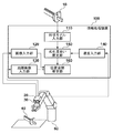
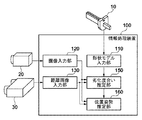
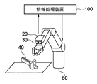
図1のブロック図により実施例1の情報処理装置100の構成例を示す。形状モデル入力部110は、対象物40の形状を表す三次元形状モデル10を入力し、三次元形状モデル10を劣化推定部150に出力する。なお、三次元形状モデル10は、情報処理装置100の内部または外部の記憶装置、あるいは、情報処理装置100が接続された有線または無線ネットワーク上のサーバ装置などに格納されている。
[Device configuration]
The block diagram of FIG. 1 shows an example of the configuration of the
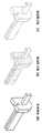
図2により三次元形状モデル10を説明する。図2(a)は物体形状の一例を示し、当該物体形状は、図2(b)に示す局所面特徴および図2(c)に示す局所線特徴によって構成される三次元形状モデル10によって表される。局所面特徴は、三次元位置と三次元法線方向から構成される物体表面上の局所的な三次元平面情報を示す。また、局所線特徴は、三次元位置と三次元線分方向から構成される物体輪郭上の局所的な三次元線分情報を示す。なお、単に「幾何特徴」と称した場合、局所面特徴と局所線特徴の両方を指すことにする。
The three-
三次元形状モデル10として保持される形状情報は、対象の物体形状を表す三次元的な幾何情報であればよく、表現形式に制限はない。例えば、単純な三次元点の集合や、稜線を表す三次元ラインの集合、三つの三次元点で定義される面および線の集合として表されるポリゴン形式の形状情報など、他の表現を用いてもよい。
The shape information held as the three-
画像入力部120は、画像撮像装置20が出力する二次元画像を入力する。画像撮像装置20は、通常の二次元画像を撮影するカメラである。画像撮像装置20が撮影する二次元画像は、濃淡画像でもよいし、カラー画像でもよい。以下では、画像撮像装置20が濃淡画像を撮影するとして説明を行う。画像撮像装置20の焦点距離や主点位置、レンズ歪みパラメータなどの内部パラメータは、画像撮像装置20として使用する機器の仕様を参照するか、非特許文献1が開示する方法によって事前にキャリブレーションしておく。
The
距離画像入力部130は、距離画像撮像装置30が出力する距離画像を入力する。距離画像撮像装置30として、対象物40の表面上の点の位置情報である三次元座標を計測して距離情報を示す距離画像を出力する距離センサが用いられる。距離画像は、各画素が奥行き情報を有する画像である。
The distance
距離センサとして、波長が異なる色IDを付与したマルチスリットラインを対象物40に照射し、その反射光をカメラで撮像して、三角測量によって距離計測を行うワンショットアクティブ式のセンサを利用することができる。しかし、距離センサは、これに限られるものではなく、光の飛行時間を利用するTime-of-flight方式のセンサを用いてもよい。あるいは、ステレオカメラが撮影した画像から三角測量によって各画素の奥行きを計算するパッシブ式のセンダでもよい。その他、距離画像を計測可能なセンサであれば、如何なるセンサも利用可能である。
As a distance sensor, use a one-shot active sensor that irradiates the
画像撮像装置20の光軸と距離画像撮像装置30の光軸が一致し、二次元画像撮像装置20が出力する濃淡画像の各画素と、距離画像撮像装置30が出力する距離画像の各画素の対応関係が既知であると想定する。
The optical axis of the
ただし、本発明の適用は、濃淡画像と距離画像が同一視点である場合に限られるものではない。例えば、画像撮像装置20と距離画像撮像装置30が異なる位置姿勢にあり、濃淡画像と距離画像がそれぞれ別の視点から撮影されてもよい。その場合、画像撮像装置20と距離画像撮像装置30の間(以下、撮像装置間)の相対的な位置姿勢を既知として、距離画像中の三次元点群を濃淡画像に投影して、濃淡画像の各画素と距離画像の各画素の対応関係を取得する。言い替えれば、同一の対象物40を撮影可能な撮像装置間の相対的な位置姿勢が既知であり、それらの画像の間の対応関係が計算可能であれば、それら撮像装置の位置関係はとくに制限されない。
However, the application of the present invention is not limited to the case where the grayscale image and the distance image are at the same viewpoint. For example, the
速度入力部140は、撮像装置(二次元画像撮像装置20および距離画像撮像装置30)と対象物40の間の相対的な位置姿勢の速度(以下、相対速度)をロボット60から入力する。相対速度は、三次元的な相対位置の速度と三次元的な姿勢の速度により構成される六自由度のパラメータにより表現される。なお、以下では、画像撮像装置20と距離画像撮像装置30を合わせた撮像装置を「撮像装置320」と称することにする。
The
ロボット60は、回転または並進移動軸からなる可動軸を複数有し、撮像装置320の位置姿勢を変更するための可動機器であり、アーム先端に撮像装置320を装着した、六軸の回転可動軸により構成される六自由度ロボットアームである。
The
撮像装置320は、アーム先端に装着されるものとする。アーム先端から撮像装置320までの位置姿勢は、撮像装置320のオフセット位置姿勢として予め取得し、以後は変化がないものとして保持する。つまり、撮像装置320の位置姿勢は、アーム先端の位置姿勢にオフセット位置姿勢を加えることで算出される。 The imaging device 320 is assumed to be attached to the tip of the arm. The position / orientation from the arm tip to the imaging device 320 is acquired in advance as the offset position / orientation of the imaging device 320, and is maintained as no change thereafter. That is, the position and orientation of the imaging device 320 is calculated by adding the offset position and orientation to the position and orientation of the arm tip.
撮像装置320と対象物40の相対的な位置姿勢が単位時間当りに移動する量を示す相対速度は、位置姿勢の取得時刻の間の撮像装置320の位置姿勢の差分から算出される。例えば、撮像装置320の相対速度は、ロボット60のモーション情報から取得することができる。つまり、ロボット60の制御モジュールは、アーム先端に装着された撮像装置320の位置姿勢における三次元的な速度を計算し、相対速度を示す情報を速度入力部140に入力する。
The relative speed indicating the amount by which the relative position and orientation of the imaging device 320 and the
ロボット60として用いる機器は、上記に限られるものではく、例えば、七軸回転軸を有する垂直多関節型ロボットや、スカラ型ロボット、パラレルリンクロボットでもよい。その他、回転または並進移動軸からなる可動軸を複数有し、モーション情報が取得できれば、如何なる形式のロボットでもよい。
The device used as the
相対速度の取得はロボット60のモーション情報を用いる方法に限られない。例えば、撮像装置320に磁気センサや超音波センサなど六自由度の位置および姿勢を計測する物理センサを取り付け、それらセンサの出力から相対速度を算出してもよい。また、撮像の間における撮像装置320の移動が回転運動に限定することができれば、撮像装置320にジャイロセンサを取り付け、その回転速度を計測してもよい。また、撮像装置320が固定され、対象物40が動く場合、対象物40に上述したセンサを取り付け、センサが出力する情報から相対速度を算出してもよい。言い替えれば、撮像装置320と対象物40の相対速度が算出できれば、如何なる方法を用いてもよく、手段や機器の選択に制限はない。
The acquisition of the relative speed is not limited to the method using the motion information of the
劣化度合い推定部150は、詳細は後述するが、三次元形状モデル入力部110から入力される三次元形状モデル10および速度入力部140から入力される相対速度から、濃淡画像の観測情報および距離画像の観測情報の情報劣化度合いを推定する。本実施例では、観測情報の劣化度合いとして、各画像のモーションブラー量を推定する。つまり、濃淡画像のエッジが露光時間に画像面を移動した量と、距離画像の三次元点群が測定時間に三次元空間を移動した量をモーションブラー量として推定する。つまり、モーションブラー量は、露光(測定)時間に、各観測情報が移動した量を表す。
Although the details will be described later, the deterioration
観測情報の劣化度合いを示す情報は、モーションブラー量に限られるものではなく、撮像装置320と対象物40の相対的な移動に基づいて観測情報が劣化する量を表すことができる情報であればよい。例えば、距離画像の観測情報の劣化度合いを、三次元座標ではなく、距離計測用パターン光の投影画像中のブラー量として表現してもよい。また、濃淡画像の観測情報の劣化度合いを、濃淡画像のエッジを三次元空間に逆投影して算出した、三次元空間における移動量として表現してもよい。
The information indicating the degree of deterioration of the observation information is not limited to the amount of motion blur, as long as the information can represent the amount of deterioration of the observation information based on the relative movement of the imaging device 320 and the
位置姿勢推定部160は、詳細は後述するが、推定されたモーションブラー量、濃淡画像の観測情報および距離画像の観測情報、並びに、三次元形状モデル10に基づき、撮像装置320と対象物40の間の位置および姿勢を推定する。
Although the details will be described later, the position /
なお、情報処理装置100の各構成および後述する処理や機能は、コンピュータ機器である情報処理装置100のCPUが、RAMをワークメモリとして、ROMなどの不揮発性メモリなどの記録媒体に格納されたプログラムを実行することにより実現される。
Each configuration of the
[位置姿勢の推定処理]
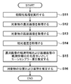
図3のフローチャートにより実施例1の情報処理装置100による位置姿勢の推定処理を説明する。
[Position and orientation estimation processing]
The position / orientation estimation process performed by the
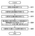
例えば、図示しない操作パネルを介して位置姿勢の推定の開始が指示されると、情報処理装置100は初期化処理を行う(S11)。初期化処理において、撮像装置320に対する対象物40の位置および姿勢の概略値(以下、概略位置姿勢)が入力される。例えば、対象物40が配置された凡その位置や姿勢が予め分かっているとして、その値が概略値として入力される。
For example, when the start of position and orientation estimation is instructed via an operation panel (not shown), the
概略位置姿勢の設定方法は上記に限られず、例えば、情報処理装置100が時間軸方向に連続した計測を行うものとして、前回の計測値を概略位置姿勢として用いてもよい。また、過去の位置および姿勢の計測に基づき、対象物40の速度や角速度を時系列フィルタによって推定し、過去の位置および姿勢と推定された速度や加速度から予測される現在の位置および姿勢を概略位置姿勢としてもよい。あるいは、様々な姿勢で撮影した対象物40の画像をテンプレートとして保持し、入力される濃淡画像とテンプレートマッチングにより、対象物40の凡その位置と姿勢を推定し、その推定値を概略位置姿勢としてもよい。
The method for setting the approximate position and orientation is not limited to the above, and for example, the previous measurement value may be used as the approximate position and orientation, assuming that the
勿論、他のセンサによる対象物40の位置および姿勢の計測が可能な場合は、当該センサの出力値を概略位置姿勢に用いてもよい。センサは、例えばトランスミッタが発する磁界を対象物40に装着されたレシーバが検出して位置および姿勢を計測する磁気式センサや、対象物40上に配置したマーカをシーンに固定されたカメラが撮影して位置および姿勢を計測する光学式センサでもよい。その他、六自由度の位置および姿勢を計測するセンサであれば如何なるセンサでも利用することができる。
Of course, when the position and orientation of the
次に、画像入力部120は、対象物40の濃淡画像を取得する(S12)。つまり、画像撮像装置20から濃淡画像と、その撮影における露光時間Tiを取得する。
Next, the
次に、距離画像入力部130は、対象物40の距離画像を取得する(S13)。つまり、距離画像撮像装置30から距離画像と、その撮影(測定)時の測定時間Trを取得する。なお、距離画像には、距離画像撮像装置30から対象物40の表面までの距離が記録されている。前述したように、画像撮像装置20と距離画像撮像装置30の光軸は一致しているため、濃淡画像の各画素と距離画像の各画素の対応は既知である。
Next, the distance
次に、速度入力部140は、相対速度を取得する(S14)。相対速度は、三次元位置の速度情報(Vx, Vy, Vz)および三次元姿勢の速度情報(Vwx, Vwy, Vwz)から構成される六次元ベクトル↑Vとして取得される。
↑V = [Vx Vy Vz Vwx Vwy Vwz]T … (1)
ここで、↑はベクトルを表す、
Tは転置行列を表す。
Next, the
↑ V = [Vx Vy Vz Vwx Vwy Vwz] T … (1)
Where ↑ represents a vector,
T represents a transposed matrix.
相対速度の取得方法は、上述の方法に限られるものではない。例えば、ロボット60の制御モジュールからアーム先端の位置姿勢を取得し、アーム先端の位置姿勢に撮像装置320の位置姿勢オフセットを加えて、所定の時刻の間における撮像装置320の位置姿勢の差分から相対速度を算出してもよい。撮像装置320の六自由度の位置姿勢の速度を取得することができる方法であれば、計算方法およびセンサの選択に制限はない。
The method for acquiring the relative speed is not limited to the above-described method. For example, the position and orientation of the arm tip is obtained from the control module of the
次に、劣化度合い推定部150は、取得された相対速度に基づき、濃淡画像の観測情報および距離画像の観測情報の劣化度合いとしてモーションブラー量を推定する(S15)。詳細は後述するが、観測情報に対応付けられる三次元形状モデル10の局所線特徴および局所面特徴ごとにモーションブラー量が推定される。
Next, the deterioration
次に、位置姿勢推定部160は、詳細は後述するが、濃淡画像および距離画像と、三次元形状モデル10の間の対応を算出し、モーションブラー量の推定値に基づき対象物40の位置および姿勢を推定する(S16)。
Next, as will be described in detail later, the position /
●劣化度合い推定部
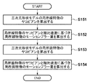
図4のフローチャートにより劣化度合いの推定処理(S15)を説明する。
Deterioration degree estimation unit Deterioration degree estimation processing (S15) will be described with reference to the flowchart of FIG.
劣化度合い推定部150は、三次元形状モデル10の局所線特徴のヤコビアンを算出する(S151)。局所線特徴のヤコビアンは、位置姿勢六自由度のパラメータが僅かに変化した際、局所線特徴と画像エッジの間の画像上の距離が変化する割合を表す値である。
The deterioration
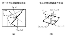
図5によりヤコビアンを説明する。図5(a)は、局所線特徴と濃淡画像の画像特徴の間の直線-点間距離の計算を説明する図である。対象物40の概略位置姿勢sに基づき、局所線特徴を画像に投影した場合、局所線特徴と対応する画像特徴の間の符号付距離(以下、第一の対応間距離)err2Dは下式よって算出される。
err2D = Nu(u' - u) + Nv(v' - v) … (2)
ここで、(u, v)は局所線特徴を投影位置、
(Nu, Nv)は投影位置の法線方向(単位ベクトル)、
(u', v')は局所線特徴に対応する画像特徴の座標。
The Jacobian will be described with reference to FIG. FIG. 5 (a) is a diagram for explaining the calculation of the line-point distance between the local line feature and the image feature of the grayscale image. When a local line feature is projected onto an image based on the approximate position and orientation s of the
err 2D = Nu (u '-u) + Nv (v'-v)… (2)
Where (u, v) is the local line feature projected position,
(Nu, Nv) is the normal direction (unit vector) of the projection position,
(u ', v') is the coordinates of the image feature corresponding to the local line feature.
対象物40の概略位置姿勢sは六次元ベクトルであり、対象物40の位置を表す三つの要素(s1, s2, s3)と姿勢を表す三つの要素(s4, s5, s6)を有する。姿勢を表す三つの要素は、例えばオイラー角による表現や、方向が原点を通る回転軸を表してノルムが回転角を表す三次元ベクトルなどによって表現される。概略位置姿勢sの各パラメータで、第一の対応間距離err2Dを偏微分して局所線特徴のヤコビアン行列J2Dが算出される。
J2D = [∂err2D/∂s1 ∂err2D/∂s2 ∂err2D/∂s3 ∂err2D/∂s4 ∂err2D/∂s5 ∂err2D/∂s6] …(3)
The approximate position and orientation s of the
J 2D = [∂err 2D / ∂s1 ∂err 2D / ∂s2 ∂err 2D / ∂s3 ∂err 2D / ∂s4 ∂err 2D / ∂s5 ∂err 2D / ∂s6]… (3)
偏微分の結果として画像特徴の座標(u', v')の項が消え、ヤコビアン行列は、局所線特徴の情報と概略位置姿勢sのみから算出することが可能である。以上の手順を、各局所線特徴に対して行い、局所線特徴ごとのヤコビアンが計算される。 As a result of the partial differentiation, the term of the coordinates (u ′, v ′) of the image feature disappears, and the Jacobian matrix can be calculated only from the local line feature information and the approximate position and orientation s. The above procedure is performed for each local line feature, and a Jacobian for each local line feature is calculated.
次に、劣化度合い推定部150は、局所線特徴のヤコビアンと相対速度に基づき、局所線特徴のモーションブラー量を算出する(S152)。濃淡画像の露光時間Tiに、撮像装置320が相対速度↑Vで動くことにより発生する、局所線特徴と濃淡画像のエッジの間の距離変化Veは下式により算出される。
Ve = Ti・J2D・↑V … (4)
Next, the degradation
Ve = Ti ・ J 2D・ ↑ V… (4)
距離変化Veはスカラ量であり、露光時間Tiに、画像平面に投影した局所線特徴の二次元位置が移動する量を表す。局所線特徴のモーションブラー量と、局所線特徴に対応する濃淡画像の観測情報のモーションブラー量が同一と仮定すると、距離変化Veは、局所線特徴と対応する濃淡画像の観測情報のモーションブラー量と見做すことができる。以上の処理をすべての局所線特徴に対して行い、すべての局所線特徴についてモーションブラー量を算出する。 The distance change Ve is a scalar amount, and represents the amount by which the two-dimensional position of the local line feature projected on the image plane moves during the exposure time Ti. Assuming that the amount of motion blur in the local line feature and the amount of motion blur in the grayscale image corresponding to the local line feature are the same, the distance change Ve is the amount of motion blur in the grayscale image corresponding to the local line feature. Can be considered. The above processing is performed for all local line features, and motion blur amounts are calculated for all local line features.
次に、劣化度合い推定部150は、三次元形状モデル10の局所面特徴のヤコビアンを算出する(S153)。局所面特徴のヤコビアンは、位置姿勢六自由度のパラメータが僅かに変化した際、局所面特徴と距離点の間の三次元空間の距離が変化する割合を表す値である。
Next, the deterioration
図5(b)は、局所面特徴と対応点(距離画像の三次元点)の間の面-点間距離の計算を説明する図である。対象物40の概略位置姿勢sに基づき、局所面特徴のカメラ座標系に投影した場合の局所面特徴と対応する距離画像の三次元点の間の三次元空間の符号付距離(第二の対応間距離)err3Dは下式よって算出される。
err3D = Nx(x' - x) + Ny(y' - y) + Nz(z' - z) … (5)
ここで、(x, y, z)は局所面特徴の投影座標、
(Nx, Ny, Nz)は投影座標の法線方向(単位ベクトル)、
(x', y', z')は局所面特徴に対応する距離画像の三次元点の座標。
FIG. 5 (b) is a diagram for explaining the calculation of the surface-to-point distance between the local surface feature and the corresponding point (three-dimensional point of the distance image). Based on the approximate position and orientation s of the
err 3D = Nx (x '-x) + Ny (y'-y) + Nz (z '-z)… (5)
Where (x, y, z) is the projected coordinates of the local surface features,
(Nx, Ny, Nz) is the normal direction (unit vector) of the projected coordinates,
(x ', y', z ') are the coordinates of the 3D point of the distance image corresponding to the local surface feature.
そして、局所線特徴のヤコビアンと同様に、仮想カメラの概略位置姿勢sの各パラメータで、第二の対応間距離err3Dを偏微分して局所面特徴のヤコビアン行列J3Dが算出される。
J3D = [∂err3D/∂s1 ∂err3D/∂s2 ∂err3D/∂s3 ∂err3D/∂s4 ∂err3D/∂s5 ∂err3D/∂s6] …(6)
Similarly to the Jacobian of the local line feature, the second correspondence distance err 3D is partially differentiated with each parameter of the approximate position and orientation s of the virtual camera to calculate the Jacobian matrix J 3D of the local surface feature.
J 3D = [∂err 3D / ∂s1 ∂err 3D / ∂s2 ∂err 3D / ∂s3 ∂err 3D / ∂s4 ∂err 3D / ∂s5 ∂err 3D / ∂s6]… (6)
偏微分の結果として距離画像の三次元点の座標(x', y', z')の項が消え、ヤコビアン行列は、局所面特徴の情報と概略位置姿勢sのみから算出することが可能である。以上の手順を、各局所面特徴に対して行い、局所面特徴ごとのヤコビアンが計算される。 As a result of the partial differentiation, the coordinate (x ', y', z ') term of the 3D point of the distance image disappears, and the Jacobian matrix can be calculated only from the local surface feature information and the approximate position and orientation s. is there. The above procedure is performed for each local surface feature, and a Jacobian for each local surface feature is calculated.
次に、劣化度合い推定部150は、局所面特徴のヤコビアンと相対速度に基づき、局所面特徴のモーションブラー量を算出する(S154)。距離画像の測定時間Trに、撮像装置320が相対速度↑Vで動くことによって発生する、局所面特徴と距離画像の距離点の間の距離変化Vrは下式により算出される。
Vr = Tr・J3D・↑V … (7)
Next, the deterioration
Vr = Tr ・ J 3D・ ↑ V… (7)
距離変化Vrはスカラ量であり、測定時間Trに、三次元空間において局所面特徴が移動する量を表す。局所面特徴のモーションブラー量と、局所面特徴に対応する距離画像の観測情報のモーションブラー量が同一と仮定すると、距離変化Vrは、局所面特徴と対応する距離画像の観測情報のモーションブラー量と見做すことができる。以上の処理をすべての局所線特徴に対して行い、すべての局所特徴についてモーションブラー量を算出する。 The distance change Vr is a scalar amount, and represents the amount by which the local surface feature moves in the three-dimensional space at the measurement time Tr. Assuming that the amount of motion blur of the local surface feature and the amount of motion blur of the observation information of the distance image corresponding to the local surface feature are the same, the distance change Vr is the amount of motion blur of the observation information of the distance image corresponding to the local surface feature. Can be considered. The above processing is performed for all local line features, and motion blur amounts are calculated for all local features.
●位置姿勢推定部
図6のフローチャートにより位置姿勢の推定処理(S16)を説明する。
Position / Orientation Estimation Unit The position / orientation estimation process (S16) will be described with reference to the flowchart of FIG.
位置姿勢推定部160は、対象物40の概略位置姿勢sに基づき、濃淡画像のエッジと三次元形状モデル10の局所線特徴の間の対応付けを行う(S161)。概略位置姿勢sと校正済みの画像撮像装置30の内部パラメータを用いて、局所線特徴を濃淡画像へ投影し、局所線特徴の投影位置を算出し、濃淡画像のエッジと局所線特徴を対応付ける。各局所線特徴に対応して複数のエッジが検出された場合、画像上で、当該局所線特徴に最も近いエッジが対応付けの対象である。
The position /
次に、位置姿勢推定部160は、概略位置姿勢sに基づき、距離画像の三次元点群と三次元形状モデル10の局所面特徴の間の対応付けを行う(S162)。概略位置姿勢sと校正済みの距離画像撮像装置30の内部パラメータを用いて、各局所面特徴を距離画像へ投影し、各局所面特徴に対応する距離画像の距離点を、当該局所特徴面に対応する三次元点として対応付ける。
Next, the position /
次に、位置姿勢推定部160は、各局所線特徴に対応する濃淡画像のエッジを示す対応データと、各局所面特徴に対応する三次元点を示す対応データに基づき、対象物40の位置および姿勢を推定する。その際、位置姿勢推定部160は、対応データに基づき、計測データと三次元形状モデル10の間の誤差を最小にする概略位置姿勢sの補正値Δsを算出する。以下では、補正値Δsの算出について詳細に説明する。
Next, the position /
濃淡画像のエッジと対応付けられた局所線特徴の数をi-1として、各局所線特徴とエッジの対応間距離をerr2Di、そのヤコビアンをJ2Diとする。一方、距離画像中の距離点と対応付けられた局所面特徴の数をj-1として、各局所面特徴と距離点の対応間距離をerr3Dj、そのヤコビアンをJ3Djとする。各対応間距離(誤差)を最小化する概略位置姿勢sの補正値Δsは下の線形連立方程式によって表すことができる。
┌ ┐┌ ┐ ┌ ┐
│J2D0││Δs1│ │err2D0│
│ : ││Δs2│ │ : │
│J2Di││Δs3│ │err2Di│
│J3D0││Δs4│=│err3D0│ … (8)
│ : ││Δs5│ │ : │
│J3Dj││Δs6│ │err3Dj│
└ ┘└ ┘ └ ┘
The number of local line features associated with the edge of the grayscale image is i-1, the distance between the correspondence between each local line feature and the edge is err 2D i, and its Jacobian is J 2D i. On the other hand, the number of local surface features associated with distance points in the distance image is j-1, the distance between the correspondence between each local surface feature and the distance point is err 3D j, and its Jacobian is J 3D j. The correction value Δs of the approximate position and orientation s that minimizes the distance (error) between the correspondences can be expressed by the following linear simultaneous equations.
┌ ┐┌ ┐ ┌ ┐
│J 2D 0││Δs1│ │err 2D 0│
│: ││Δs2│ │: │
│J 2D i││Δs3│ │err 2D i│
│J 3D 0││Δs4│ = │err 3D 0│… (8)
│: ││Δs5│ │: │
│J 3D j││Δs6│ │err 3D j│
└ ┘└ ┘ └ ┘
ここで、ヤコビアンをJ、対応間距離(誤差)をEとすると、式(8)を下式で表すことができる。
JΔs = E … (9)
Here, when the Jacobian is J and the distance (error) between the correspondences is E, Expression (8) can be expressed by the following expression.
JΔs = E… (9)
各対応データにモーションブラー量が大きい対応データが存在すると、補正値Δsの精度が低下する。そこで、位置姿勢推定部160は、局所線特徴ごと、局所面特徴ごとに計算されたモーションブラー量に基づき、各対応データの重みを算出する(S163)。言い替えれば、モーションブラー量が小さい対応データを重用するように、線形連立方程式を組み立て、モーションブラー量が大きい対応データには小さな重みを与え、モーションブラー量が小さい対応データには大きな重みを与える。モーションブラー量をvとする場合、重みw(v)は、例えば下式に示すようなTukeyの関数により与えられる。
if (v ≦ c)
w(v) = {1 + (v/c)2}2;
else
w(v) = 0; … (10)
ここで、cは定数。
If there is correspondence data with a large amount of motion blur in each correspondence data, the accuracy of the correction value Δs decreases. Therefore, the position /
if (v ≤ c)
w (v) = {1 + (v / c) 2 } 2 ;
else
w (v) = 0 ;… (10)
Where c is a constant.
重みを与える関数は、Tukeyの関数である必要はなく、例えばHuberの関数など、モーションブラー量vが大きい場合は小さな重みを与え、モーションブラー量vが小さい場合は大きな重みを与える関数であればよい。また、定数cは、位置姿勢の推定に有効なモーションブラー量vを規定する閾値であり、位置姿勢の推定において許容する精度を基に設定してもよいし、モーションブラー量vの全体の最大値から決定してもよい。定数cの設定方法に制限はなく、モーションブラー量vに基づいて重みを設定することができればよい。 The function that gives the weight does not need to be a Tukey function. For example, a Huber function is a function that gives a small weight when the motion blur amount v is large and gives a large weight when the motion blur amount v is small. Good. The constant c is a threshold value that prescribes an effective motion blur amount v for position / orientation estimation, and may be set based on the accuracy allowed for position / orientation estimation, or the maximum motion blur amount v as a whole. It may be determined from the value. There is no limitation on the setting method of the constant c, and it is sufficient that the weight can be set based on the motion blur amount v.
局所線特徴の対応データに与える重みをw2Di、局所面特徴の対応データに与える重みをw3Djとして、重み行列Wを下式のように定義する。
┌ ┐
│w2D0 0│
│ : │
W = │ w2Di │
│ w3D0 │ … (11)
│ : │
│0 w3Dj│
└ ┘
The weight matrix W is defined as follows, where w 2D i is the weight given to the correspondence data of the local line feature and w 3D j is the weight given to the correspondence data of the local surface feature.
┌ ┐
│w 2D 0 0│
│ : │
W = │ w 2D i │
│ w 3D 0 │… (11)
│ : │
│0 w 3D j│
└ ┘
重み行列Wは、対角成分以外はすべて0のLc×Lc正方行列であり、対角成分は重みw2Di、w3Djである。この重み行列Wを用いて、式(9)を下式のように変形する。
WJΔs = WE … (12)
The weight matrix W is an Lc × Lc square matrix that is all zero except for the diagonal components, and the diagonal components are weights w 2D i and w 3D j. Using this weight matrix W, equation (9) is transformed into the following equation.
WJΔs = WE… (12)
位置姿勢推定部160は、次式に示す一般化逆行列を用いて式(12)を解き、補正値Δsを算出する(S164)。
Δs = (JTWJ)-1JTWE … (13)
The position /
Δs = (J T WJ) -1 J T WE… (13)
位置姿勢推定部160は、式(13)によって得られる補正値Δsを用いて、対象物40の概略位置姿勢sを更新する(s+Δs)(S165)。ここでは、非線形最適化手法としてGauss-Newton法を用いる例を説明した。しかし、非線形最適化手法は、これに限られるものではなく、Newton-Raphson法、Levenberg-Marquardt法、最急降下法、共役勾配法などのその他の非線形最適化手法を用いてもよい。
The position /
次に、位置姿勢推定部160は、ステップS165で更新した位置姿勢が収束しているか否か、言い替えれば、反復計算が必要か否かを判定する(S166)。つまり、補正値Δsがほぼ0の場合や、誤差ベクトルの二乗和の補正前と補正後の差がほぼ0の場合は収束と判定する。また、未収束の場合は、処理をステップS161に戻し、更新後の概略位置姿勢sを用いて、再度、位置姿勢の算出処理を行う。
Next, the position /
更新した位置姿勢が収束していると判定すると、位置姿勢推定部160は、当該位置姿勢を撮像装置320と対象物40の間の相対的な位置姿勢の最終的な推定値として決定し(S167)、位置姿勢の推定処理を終了する
When it is determined that the updated position / orientation has converged, the position /
このように、対象物40と撮像装置320の間の相対速度と対象物40の形状に基づき、濃淡画像および距離画像の観測情報ごとの劣化度合いを判定し、劣化度合いが小さい観測情報が重用されるように重みを設定して位置姿勢を推定する。従って、移動中撮像によりモーションブラーが発生して観測情報の劣化が発生している場合も、位置姿勢を高精度に推定することができる。
Thus, based on the relative speed between the
以下、本発明にかかる実施例2の計測および情報処理を説明する。なお、実施例2において、実施例1と略同様の構成については、同一符号を付して、その詳細説明を省略する。 Hereinafter, measurement and information processing according to the second embodiment of the present invention will be described. Note that the same reference numerals in the second embodiment denote the same parts as in the first embodiment, and a detailed description thereof will be omitted.
実施例1では、対象物40と撮像装置320の相対速度、および、対象物40の形状に基づき、濃淡画像および距離画像の観測情報の劣化度合いとしてモーションブラー量を予測する方法を説明した。実施例2では、相対速度を事前知識として用いずに、取得した濃淡画像および距離画像の観測情報像からモーションブラー量を推定する方法を説明する。
In the first embodiment, the method of predicting the motion blur amount as the deterioration degree of the observation information of the grayscale image and the distance image based on the relative speed between the
[装置の構成]
図7のブロック図により実施例2の情報処理装置100の構成例を示す。図1に示す構成と異なるのは、速度入力部140を備えないことと、画像入力部120と距離画像入力部130の出力先として劣化度合い推定部150が追加されている点である。
[Device configuration]
A block diagram of FIG. 7 shows a configuration example of the
実施例2において、画像入力部120における露光時間の取得および距離画像入力部130における測定時間の取得は必須項目ではない。ただし、距離画像取得部130は、距離画像に加えて、距離画像の算出元である、マルチスリットラインを対象物40に照射して撮影された測定用のパターン光画像を距離画像撮像装置30から取得する。
In the second embodiment, acquisition of exposure time in the
劣化度合い推定部150は、撮像装置320により撮影された濃淡画像および距離画像から、濃淡画像および距離画像の観測情報の劣化度合いを推定する。詳細は後述するが、劣化度合いとして、モーションブラーを含む観測情報の暈けの程度が推定される。
The deterioration
[位置姿勢の推定処理]
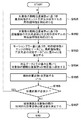
図8のフローチャートにより実施例2の情報処理装置100による位置姿勢の推定処理を説明する。ステップS11からS13の処理は実施例1と略同様であり、詳細説明を省略する。ただし、前述したように、露光時間の取得と測定時間の取得は行われず、距離画像に加えてパターン光画像が取得される。
[Position and orientation estimation processing]
The position / orientation estimation process performed by the
次に、劣化度合い推定部150は、濃淡画像およびパターン光画像を用いて、濃淡画像および距離画像の観測情報の劣化度合いとしてモーションブラーを含む暈け量を算出する(S24)。つまり、濃淡画像およびパターン光画像それぞれの画素ごとに暈け量を算出し、濃淡画像の暈け量を示す第一の暈け量画像と、距離画像に関する暈け量を示す第二の暈け量画像を生成する。第一および第二の暈け量画像は同一サイズであり、画素ごとの対応が取れているものとする。
Next, the deterioration
画像から画素ごとの暈け算出して暈け量画像を生成する手法は、例えば、非特許文献2に開示された暈けの推定手法を用いればよい。劣化度合い推定部150は、非特許文献2に開示された暈けの推定手法を濃淡画像およびパターン光画像それぞれに適用し、第一および第二の暈け量画像を生成する。
For example, the blur estimation method disclosed in Non-Patent Document 2 may be used as a method for generating a blur amount image by calculating blur for each pixel from an image. Deterioration
なお、単一画像から暈け量を推定する手法は、非特許文献2に開示された手法に限られず、画像から画素ごとに暈け量を推定することができる方法であれば如何なる手法を用いてもよい。 Note that the method for estimating the amount of blur from a single image is not limited to the method disclosed in Non-Patent Document 2, and any method can be used as long as the amount of blur can be estimated for each pixel from the image. May be.
また、パターン光画像から暈け量を推定せずに、距離画像から直接暈け量を推定し、第二の暈け量画像を生成してもよい。例えば、パターン光画像に暈けが発生すると、そこから算出される距離値は、近傍で同じ平面上にある点の距離値でもばらつきが大きくなることが知られている。そこで、距離画像の画素ごとに近傍領域におけるばらつき量を算出し、ばらつき量を暈け量と見做して、第二の暈け量画像を生成すればよい。 Alternatively, the second blur amount image may be generated by estimating the blur amount directly from the distance image without estimating the blur amount from the pattern light image. For example, when blur occurs in the pattern light image, it is known that the distance value calculated therefrom has a large variation even if the distance value is a point on the same plane in the vicinity. Therefore, the second blur amount image may be generated by calculating the variation amount in the vicinity region for each pixel of the distance image and considering the variation amount as the blur amount.
次に、位置姿勢推定部160は、濃淡画像と局所線特徴の間の対応データ、および、距離画像と局所面特徴の間の対応データを生成し、ステップS24で算出された暈け量に基づき、対象物40の位置および姿勢を算出する(S25)。ステップS25の位置姿勢の推定処理は、実施例1のステップS16の処理と略同一であり、ステップS16の処理と異なる点についてのみ説明する。
Next, the position /
実施例2では、局所線特徴および局所面特徴ごとのモーションブラー量の算出を行わない。そこで、第一の暈け量画像を参照して濃淡画像の観測情報ごとの暈け量を設定し、第二の暈け量画像を参照して距離画像の観測情報ごとの暈け量を設定して、観測情報ごとの暈け量に基づき各対応データの重みを算出する(図6のS163)。そして、対応データと重みを用いて補正値Δsを算出する(図6のS164)。 In the second embodiment, the motion blur amount for each local line feature and local surface feature is not calculated. Therefore, refer to the first blur amount image to set the blur amount for each observation information of the gray image, and refer to the second blur amount image to set the blur amount for each observation information of the distance image. Then, the weight of each corresponding data is calculated based on the amount of profit for each observation information (S163 in FIG. 6). Then, the correction value Δs is calculated using the correspondence data and the weight (S164 in FIG. 6).
このように、濃淡画像およびパターン光画像(または距離画像)から、濃淡画像および距離画像の観測情報の劣化度合いとして暈け量を算出し、暈け量が小さい観測情報が重用されるように重みを設定して位置姿勢を推定する。従って、移動中撮像によりモーションブラーが発生して観測情報の劣化が発生している場合も、位置姿勢を高精度に推定することができる。 Thus, the amount of blur is calculated from the grayscale image and the pattern light image (or the distance image) as the degree of deterioration of the observation information of the grayscale image and the distance image, and weights are used so that observation information with a small blur amount is used. To estimate the position and orientation. Therefore, the position and orientation can be estimated with high accuracy even when motion blur occurs due to imaging during movement and degradation of observation information occurs.
以下、本発明にかかる実施例3の計測および情報処理を説明する。なお、実施例3において、実施例1、2と略同様の構成については、同一符号を付して、その詳細説明を省略する。 Hereinafter, measurement and information processing according to the third embodiment of the present invention will be described. Note that the same reference numerals in the third embodiment denote the same parts as in the first and second embodiments, and a detailed description thereof will be omitted.
位置姿勢を推定する情報処理装置100の好適な適用事例として、以下の形態が考えられる。つまり、画像撮像装置20および距離画像撮像装置30により得られる濃淡画像と距離画像を基に対象物40の位置姿勢を推定し、推定結果に基づき産業用ロボットアームによって対象物40の把持などの作業を行う形態である。
As a suitable application example of the
図9により位置姿勢を推定する情報処理装置100の適用例を説明する。図9は、実施例1または実施例2の情報処理装置100とロボット60を用いて対象物40の位置および/または姿勢を変更するなどの操作を行う作業装置であるロボットシステムの構成例を示す。
An application example of the
ロボット60は、ロボットコントローラにより制御され、指令された位置に手先を移動させ物体の把持など操作を行う。対象物40は、作業台に載置される位置が変化するため、現在の対象物40の位置姿勢を推定し、ロボット60の把持制御などを行う必要がある。
The
画像撮像装置20は、通常の二次元画像を撮影するカメラ、距離画像撮像装置30は対象物40の表面の距離を計測する距離センサであり、対象物40の撮影が可能な位置、例えばロボットアームの先端部などに設置されている。
The
情報処理装置100は、画像撮像装置20および距離画像撮像装置30から得られる濃淡画像と距離画像に基づき対象物40の位置姿勢を推定する。推定された対象物40の位置姿勢は、ロボット60に入力され、対象物40の把持などを行うようにロボットアームが制御される。情報処理装置100による対象物40の位置姿勢の推定により、対象物40の位置が不定でも、ロボット60による対象物40の把持などの作業が可能になる。
The
[変形例]
上記の実施例においては、観測情報ごとに劣化度合いに基づく重みを設定して位置姿勢を推定する例を説明した。しかし、重みの設定方法は、上記の実施例において説明した方法に限られるものではない。
[Modification]
In the above-described embodiment, the example in which the position and orientation is estimated by setting the weight based on the degree of deterioration for each observation information has been described. However, the weight setting method is not limited to the method described in the above embodiment.
例えば、濃淡画像の観測情報と距離画像の観測情報のどちらを重視するかという、濃淡画像と距離画像ごとに利用率(重み)を設定して位置姿勢を推定してもよい。この場合、濃淡画像全体で一つの情報劣化度合いを算出し、同様に、距離画像全体で一つの情報劣化度合いを算出する。画像全体の情報劣化度合いの算出方法は、例えば、観測情報ごとの劣化度合いを算出し、それらの平均値、中央値、最大値、最小値などの統計値を画像全体の情報劣化度合いとすればよい。そして、算出した濃淡画像全体の劣化度合いと距離画像全体の劣化度合いから利用率を算出して位置姿勢を推定する。 For example, the position and orientation may be estimated by setting a utilization rate (weight) for each of the grayscale image and the distance image, that is, whether the observation information of the grayscale image or the observation information of the distance image is important. In this case, one information deterioration degree is calculated for the entire grayscale image, and similarly, one information deterioration degree is calculated for the entire distance image. The method for calculating the degree of information deterioration of the entire image is, for example, by calculating the degree of deterioration for each observation information, and using the statistical values such as the average value, median value, maximum value, and minimum value as the information deterioration degree of the entire image. Good. Then, the usage rate is calculated from the calculated degree of deterioration of the entire grayscale image and the degree of deterioration of the entire distance image to estimate the position and orientation.
利用率は、濃淡画像全体の劣化度合いと距離画像全体の劣化度合いの和を求め、各劣化度合いを和で除算する。そして、式(11)におけるw2Di、w3Djに利用率を設定して位置姿勢を推定する。その際、一方の劣化度合いが著しく大きく、利用率が0になる場合、一方の観測情報は利用されずに位置姿勢が推定される。 For the utilization rate, the sum of the deterioration degree of the entire grayscale image and the deterioration degree of the entire distance image is obtained, and each deterioration degree is divided by the sum. Then, the utilization is set to w 2D i and w 3D j in Equation (11) to estimate the position and orientation. At that time, when one of the deterioration levels is remarkably large and the utilization rate becomes 0, the position and orientation is estimated without using the other observation information.
また、画像全体の情報劣化度合いを算出するのではなく、画像の領域ごとに情報劣化度合いを算出して位置姿勢を推定してもよい。つまり、位置姿勢を推定する際に、劣化度合いが大きい観測情報の重みを小さくすることができれば、情報劣化度合いの算出方法や重みの設定方法に制限はない。 Further, instead of calculating the degree of information deterioration of the entire image, the position and orientation may be estimated by calculating the degree of information deterioration for each region of the image. That is, when estimating the position and orientation, if the weight of observation information having a large degree of deterioration can be reduced, there is no limitation on the method for calculating the degree of information deterioration and the method for setting the weight.
また、上記では、三次元形状モデル10として、局所面特徴と局所線特徴により構成されたモデル例に説明した。三次元形状モデルとして他の表現方式を用いてもよい。例えば、三点と三辺および一面により構成されるポリゴンの集合、単純な三次元点の集合、陰関数の組み合わせによりパラメトリックに三次元形状を表現する方法などを用いることもできる。
In the above description, the three-
また、パターン光の投影にはプロジェクタや液晶プロジェクタを用いればよいが、これらに限らず、パターン光の投影ができる方式の装置であればよい。例えば、DMD (digital mirror device)やLCOS (liquid crystal on silicon)を用いるプロジェクタでもよい。 In addition, a projector or a liquid crystal projector may be used for pattern light projection. However, the present invention is not limited thereto, and any apparatus that can project pattern light may be used. For example, a projector using DMD (digital mirror device) or LCOS (liquid crystal on silicon) may be used.
また、上記では、最適化計算ベースの位置姿勢の推定を説明したが、他の方法を用いることもできる。例えば、概略位置姿勢を中心とする所定の範囲において、六自由度の値が網羅的にカバーされるように多数の位置姿勢を生成し、各位置姿勢において観測できる幾何特徴と濃淡画像および距離画像のマッチングを評価して、位置姿勢を推定してもよい。 In the above description, optimization calculation-based position and orientation estimation has been described. However, other methods can be used. For example, in a predetermined range centered on the approximate position and orientation, a large number of positions and orientations are generated so that the values of six degrees of freedom are comprehensively covered, and geometric features, grayscale images, and distance images that can be observed at each position and orientation The position and orientation may be estimated by evaluating the matching.
また、上記では、濃淡画像と距離画像を同時に利用して位置姿勢を推定する例を説明した。しかし、濃淡画像のみ、距離画像のみを用いて位置姿勢を推定する場合も、本発明を適用することができる。 In the above description, the example in which the position and orientation is estimated using the grayscale image and the distance image simultaneously has been described. However, the present invention can also be applied to the case where the position and orientation is estimated using only the grayscale image and only the distance image.
[その他の実施例]
また、本発明は、以下の処理を実行することによっても実現される。即ち、上述した実施形態の機能を実現するソフトウェア(プログラム)を、ネットワーク又は各種記録媒体を介してシステム或いは装置に供給し、そのシステムあるいは装置のコンピュータ(又はCPUやMPU等)がプログラムを読み出して実行する処理である。
[Other Examples]
The present invention can also be realized by executing the following processing. That is, software (program) that realizes the functions of the above-described embodiments is supplied to a system or apparatus via a network or various recording media, and a computer (or CPU, MPU, etc.) of the system or apparatus reads the program. It is a process to be executed.
110 … 形状モデル入力部、120 … 画像入力部、130 … 距離画像入力部、150 … 劣化度合い推定部、160 … 位置姿勢推定部 110 ... Shape model input unit, 120 ... Image input unit, 130 ... Distance image input unit, 150 ... Degradation degree estimation unit, 160 ... Position and orientation estimation unit
Claims (13)
第一の撮像装置によって取得される前記物体の画像を入力する第二の入力手段と、
第二の撮像装置によって取得される前記物体の表面の位置情報を示す距離情報を入力する第三の入力手段と、
前記第一および第二の撮像装置と前記物体の間の相対的な動きによって発生する、前記画像の情報劣化度合いおよび前記距離情報の情報劣化度合いを推定する第一の推定手段と、
前記情報劣化度合いに基づき、前記物体の位置および/または姿勢を推定する際の、前記画像に関する重み、および、前記距離情報に関する重みを設定し、前記画像および/または前記距離情報、前記形状モデル、並びに、前記重みに基づき、前記物体の位置および/または姿勢を推定する第二の推定手段を有する情報処理装置。 A first input means for inputting a shape model of an object to be measured;
Second input means for inputting an image of the object acquired by the first imaging device;
Third input means for inputting distance information indicating the position information of the surface of the object obtained by the second imaging device;
First estimation means for estimating an information deterioration degree of the image and an information deterioration degree of the distance information, which are generated by relative movement between the first and second imaging devices and the object;
Based on the degree of information degradation, set the weight for the image and the weight for the distance information when estimating the position and / or orientation of the object, and the image and / or the distance information, the shape model, And an information processing apparatus having second estimation means for estimating the position and / or orientation of the object based on the weight .
前記第一の推定手段は、前記速度と前記形状モデルに基づき前記情報劣化度合いを推定する請求項1に記載された情報処理装置。 Furthermore, it has a 4th input means which inputs the speed of the said relative movement,
2. The information processing apparatus according to claim 1, wherein the first estimation unit estimates the information deterioration degree based on the speed and the shape model.
前記第一の推定手段は、前記画像から当該画像の情報劣化度合いを推定し、前記パターン光画像から前記距離情報の情報劣化度合いを推定する請求項1に記載された情報処理装置。 The third input means further inputs a pattern light image for measuring the distance information from the second imaging device,
2. The information processing apparatus according to claim 1, wherein the first estimation unit estimates an information deterioration degree of the image from the image and estimates an information deterioration degree of the distance information from the pattern light image.
第一の撮像装置によって取得される前記物体の画像を入力する第二の入力手段と、
第二の撮像装置によって取得される前記物体の表面の位置情報を示す距離情報を入力する第三の入力手段と、
前記第一および第二の撮像装置と前記物体の間の相対的な動きによって発生する、前記画像の情報劣化度合いおよび前記距離情報の情報劣化度合いを推定する第一の推定手段と、
前記形状モデルの局所線特徴と前記画像の画像特徴を対応付ける対応データ、および、前記形状モデルの局所面特徴と前記距離情報の位置情報を対応付ける対応データを生成し、前記情報劣化度合いに基づき各対応データの重みを設定し、前記対応データと前記重みを用いて前記物体の位置および/または姿勢を推定する第二の推定手段を有する情報処理装置。 A first input means for inputting a shape model of an object to be measured;
Second input means for inputting an image of the object acquired by the first imaging device;
Third input means for inputting distance information indicating the position information of the surface of the object obtained by the second imaging device;
First estimation means for estimating an information deterioration degree of the image and an information deterioration degree of the distance information, which are generated by relative movement between the first and second imaging devices and the object;
Correspondence data that associates the local line feature of the shape model with the image feature of the image, and correspondence data that associates the local surface feature of the shape model with the position information of the distance information, and each correspondence based on the degree of information deterioration An information processing apparatus comprising: a second estimation unit that sets data weights and estimates the position and / or orientation of the object using the correspondence data and the weights.
前記物体の表面の位置情報を示す距離情報を測定する第二の撮像装置と、
請求項1から請求項8の何れか一項に記載された情報処理装置とを有する計測装置。 A first imaging device for photographing an object;
A second imaging device for measuring distance information indicating positional information of the surface of the object;
9. A measuring device comprising the information processing device according to claim 1.
前記計測装置による物体の位置および/または姿勢の推定結果に基づき、前記物体あるいは前記計測装置の第一および第二の撮像装置の位置および/または姿勢を変更する操作手段とを有する作業装置。 A measuring device according to claim 9,
A work device having an operation unit that changes a position and / or posture of the object or the first and second imaging devices of the measurement device based on an estimation result of the position and / or posture of the object by the measurement device.
第一の撮像装置によって取得される前記物体の画像を入力し、
第二の撮像装置によって取得される前記物体の表面の位置情報を示す距離情報を入力し、
前記第一および第二の撮像装置と前記物体の間の相対的な動きによって発生する、前記画像の情報劣化度合いおよび前記距離情報の情報劣化度合いを推定し、
前記情報劣化度合いに基づき、前記物体の位置および/または姿勢を推定する際の、前記画像に関する重み、および、前記距離情報に関する重みを設定し、
前記画像および/または前記距離情報、前記形状モデル、並びに、前記重みに基づき、前記物体の位置および/または姿勢を推定する情報処理方法。 Enter the shape model of the object to be measured,
Input an image of the object acquired by the first imaging device;
Input distance information indicating the position information of the surface of the object acquired by the second imaging device,
Estimating an information deterioration degree of the image and an information deterioration degree of the distance information, which are generated by relative movement between the first and second imaging devices and the object;
Based on the degree of information deterioration, set the weight for the image and the weight for the distance information when estimating the position and / or orientation of the object,
An information processing method for estimating a position and / or posture of the object based on the image and / or the distance information, the shape model, and the weight .
Priority Applications (2)
| Application Number | Priority Date | Filing Date | Title |
|---|---|---|---|
| JP2014094873A JP6317618B2 (en) | 2014-05-01 | 2014-05-01 | Information processing apparatus and method, measuring apparatus, and working apparatus |
| US14/695,557 US9630322B2 (en) | 2014-05-01 | 2015-04-24 | Information processing apparatus, method therefor, measurement apparatus, and working apparatus for estimating a position/orientation of a three-dimensional object based on relative motion |
Applications Claiming Priority (1)
| Application Number | Priority Date | Filing Date | Title |
|---|---|---|---|
| JP2014094873A JP6317618B2 (en) | 2014-05-01 | 2014-05-01 | Information processing apparatus and method, measuring apparatus, and working apparatus |
Publications (3)
| Publication Number | Publication Date |
|---|---|
| JP2015212644A JP2015212644A (en) | 2015-11-26 |
| JP2015212644A5 JP2015212644A5 (en) | 2017-03-16 |
| JP6317618B2 true JP6317618B2 (en) | 2018-04-25 |
Family
ID=54354552
Family Applications (1)
| Application Number | Title | Priority Date | Filing Date |
|---|---|---|---|
| JP2014094873A Expired - Fee Related JP6317618B2 (en) | 2014-05-01 | 2014-05-01 | Information processing apparatus and method, measuring apparatus, and working apparatus |
Country Status (2)
| Country | Link |
|---|---|
| US (1) | US9630322B2 (en) |
| JP (1) | JP6317618B2 (en) |
Cited By (1)
| Publication number | Priority date | Publication date | Assignee | Title |
|---|---|---|---|---|
| JP2848856B2 (en) | 1988-07-26 | 1999-01-20 | エム・アー・エヌ・ローラント・ドルツクマシーネン・アクチエンゲゼルシヤフト | Device for adjusting the relative angular position of a driven rotator |
Families Citing this family (11)
| Publication number | Priority date | Publication date | Assignee | Title |
|---|---|---|---|---|
| JP6364836B2 (en) * | 2014-03-14 | 2018-08-01 | セイコーエプソン株式会社 | Robot, robot system, and control device |
| KR101898375B1 (en) * | 2016-01-29 | 2018-09-13 | 성균관대학교산학협력단 | Apparatus for measuring displacement of 6-axis |
| JP6714393B2 (en) * | 2016-03-02 | 2020-06-24 | キヤノン株式会社 | Measuring device, system, measuring method, and article manufacturing method |
| JP6740033B2 (en) | 2016-06-28 | 2020-08-12 | キヤノン株式会社 | Information processing device, measurement system, information processing method, and program |
| US10055667B2 (en) | 2016-08-03 | 2018-08-21 | X Development Llc | Generating a model for an object encountered by a robot |
| JP6514156B2 (en) * | 2016-08-17 | 2019-05-15 | ファナック株式会社 | Robot controller |
| JP2018051728A (en) * | 2016-09-30 | 2018-04-05 | ファナック株式会社 | Detection method and detection apparatus for detecting three-dimensional position of object |
| WO2019040068A1 (en) * | 2017-08-24 | 2019-02-28 | Sony Mobile Communications Inc. | Image processing devices with efficient motion blur detection and methods of operating same |
| CN108254395B (en) | 2017-12-28 | 2023-10-13 | 清华大学 | Scanned image correction device, method and mobile scanning equipment |
| JP7031540B2 (en) | 2018-09-07 | 2022-03-08 | オムロン株式会社 | Object recognition devices, manipulators, and mobile robots |
| CN115139306B (en) * | 2022-08-31 | 2022-12-27 | 中国电子产品可靠性与环境试验研究所((工业和信息化部电子第五研究所)(中国赛宝实验室)) | Active motion precision compensation method, device, equipment and medium for industrial robot |
Family Cites Families (34)
| Publication number | Priority date | Publication date | Assignee | Title |
|---|---|---|---|---|
| US4146924A (en) * | 1975-09-22 | 1979-03-27 | Board Of Regents For Education Of The State Of Rhode Island | System for visually determining position in space and/or orientation in space and apparatus employing same |
| US4853771A (en) * | 1986-07-09 | 1989-08-01 | The United States Of America As Represented By The Secretary Of The Navy | Robotic vision system |
| US4891767A (en) * | 1988-06-02 | 1990-01-02 | Combustion Engineering, Inc. | Machine vision system for position sensing |
| JP3079186B2 (en) * | 1995-09-28 | 2000-08-21 | 株式会社小松製作所 | Structure measurement system |
| US5943476A (en) * | 1996-06-13 | 1999-08-24 | August Design, Inc. | Method and apparatus for remotely sensing orientation and position of objects |
| WO2000045229A1 (en) * | 1999-01-29 | 2000-08-03 | Georgia Tech Research Corporation | Uncalibrated dynamic mechanical system controller |
| EP2071515A1 (en) * | 2007-12-11 | 2009-06-17 | Honda Research Institute Europe GmbH | Visually tracking an object in real world using 2D appearance and multicue depth estimations |
| WO2009123956A1 (en) * | 2008-03-31 | 2009-10-08 | Abb Research | Robot parts assembly on a workpiece moving on an assembly line |
| JP5290864B2 (en) * | 2009-05-18 | 2013-09-18 | キヤノン株式会社 | Position and orientation estimation apparatus and method |
| JP5290865B2 (en) * | 2009-05-18 | 2013-09-18 | キヤノン株式会社 | Position and orientation estimation method and apparatus |
| JP5335574B2 (en) * | 2009-06-18 | 2013-11-06 | キヤノン株式会社 | Image processing apparatus and control method thereof |
| JP5567908B2 (en) * | 2009-06-24 | 2014-08-06 | キヤノン株式会社 | Three-dimensional measuring apparatus, measuring method and program |
| JP5173954B2 (en) * | 2009-07-13 | 2013-04-03 | キヤノン株式会社 | Image processing apparatus and image processing method |
| JP5393318B2 (en) * | 2009-07-28 | 2014-01-22 | キヤノン株式会社 | Position and orientation measurement method and apparatus |
| JP2011175477A (en) * | 2010-02-24 | 2011-09-08 | Canon Inc | Three-dimensional measurement apparatus, processing method and program |
| JP5618569B2 (en) * | 2010-02-25 | 2014-11-05 | キヤノン株式会社 | Position and orientation estimation apparatus and method |
| JP5746477B2 (en) * | 2010-02-26 | 2015-07-08 | キヤノン株式会社 | Model generation device, three-dimensional measurement device, control method thereof, and program |
| JP5430456B2 (en) * | 2010-03-16 | 2014-02-26 | キヤノン株式会社 | Geometric feature extraction device, geometric feature extraction method, program, three-dimensional measurement device, object recognition device |
| US8510078B2 (en) * | 2010-03-31 | 2013-08-13 | Mitsubishi Electric Research Laboratories, Inc. | Method and system for registering an object with a probe using entropy-based motion selection and Rao-Blackwellized particle filtering |
| EP2400261A1 (en) * | 2010-06-21 | 2011-12-28 | Leica Geosystems AG | Optical measurement method and system for determining 3D coordination in a measuring object surface |
| JP5624394B2 (en) * | 2010-07-16 | 2014-11-12 | キヤノン株式会社 | Position / orientation measurement apparatus, measurement processing method thereof, and program |
| JP5496008B2 (en) * | 2010-08-06 | 2014-05-21 | キヤノン株式会社 | Position / orientation measuring apparatus, position / orientation measuring method, and program |
| JP5839929B2 (en) * | 2010-11-19 | 2016-01-06 | キヤノン株式会社 | Information processing apparatus, information processing system, information processing method, and program |
| JP5839971B2 (en) * | 2010-12-14 | 2016-01-06 | キヤノン株式会社 | Information processing apparatus, information processing method, and program |
| US9182221B2 (en) * | 2011-06-13 | 2015-11-10 | Canon Kabushiki Kaisha | Information processing apparatus and information processing method |
| US9437005B2 (en) * | 2011-07-08 | 2016-09-06 | Canon Kabushiki Kaisha | Information processing apparatus and information processing method |
| US9279661B2 (en) * | 2011-07-08 | 2016-03-08 | Canon Kabushiki Kaisha | Information processing apparatus and information processing method |
| JP2013191163A (en) * | 2012-03-15 | 2013-09-26 | Sony Corp | Information processing device, information processing method, and program |
| JP5895720B2 (en) * | 2012-06-06 | 2016-03-30 | 富士通株式会社 | Subject tracking device, subject tracking method, and computer program for subject tracking |
| JP2015036632A (en) * | 2013-08-12 | 2015-02-23 | キヤノン株式会社 | Distance measuring device, imaging device, distance measuring method |
| JP6324025B2 (en) * | 2013-11-05 | 2018-05-16 | キヤノン株式会社 | Information processing apparatus and information processing method |
| JP6363863B2 (en) * | 2014-04-15 | 2018-07-25 | キヤノン株式会社 | Information processing apparatus and information processing method |
| JP6573354B2 (en) * | 2014-11-28 | 2019-09-11 | キヤノン株式会社 | Image processing apparatus, image processing method, and program |
| JP2017010092A (en) * | 2015-06-17 | 2017-01-12 | キヤノン株式会社 | Image processing apparatus, imaging device, image processing method, image processing program, and recording medium |
-
2014
- 2014-05-01 JP JP2014094873A patent/JP6317618B2/en not_active Expired - Fee Related
-
2015
- 2015-04-24 US US14/695,557 patent/US9630322B2/en not_active Expired - Fee Related
Cited By (1)
| Publication number | Priority date | Publication date | Assignee | Title |
|---|---|---|---|---|
| JP2848856B2 (en) | 1988-07-26 | 1999-01-20 | エム・アー・エヌ・ローラント・ドルツクマシーネン・アクチエンゲゼルシヤフト | Device for adjusting the relative angular position of a driven rotator |
Also Published As
| Publication number | Publication date |
|---|---|
| JP2015212644A (en) | 2015-11-26 |
| US9630322B2 (en) | 2017-04-25 |
| US20150314452A1 (en) | 2015-11-05 |
Similar Documents
| Publication | Publication Date | Title |
|---|---|---|
| JP6317618B2 (en) | Information processing apparatus and method, measuring apparatus, and working apparatus | |
| JP6180087B2 (en) | Information processing apparatus and information processing method | |
| US20200096317A1 (en) | Three-dimensional measurement apparatus, processing method, and non-transitory computer-readable storage medium | |
| CN102914293B (en) | Messaging device and information processing method | |
| JP6324025B2 (en) | Information processing apparatus and information processing method | |
| JP5904676B2 (en) | Apparatus and method for robust calibration between machine vision system and robot | |
| JP6444027B2 (en) | Information processing apparatus, information processing apparatus control method, information processing system, and program | |
| JP5567908B2 (en) | Three-dimensional measuring apparatus, measuring method and program | |
| JP6626338B2 (en) | Information processing apparatus, control method for information processing apparatus, and program | |
| JP6677522B2 (en) | Information processing apparatus, control method for information processing apparatus, and program | |
| JP2016099257A (en) | Information processing apparatus and information processing method | |
| US9914222B2 (en) | Information processing apparatus, control method thereof, and computer readable storage medium that calculate an accuracy of correspondence between a model feature and a measurement data feature and collate, based on the accuracy, a geometric model and an object in an image | |
| JP6180158B2 (en) | Position / orientation measuring apparatus, control method and program for position / orientation measuring apparatus | |
| JP5698815B2 (en) | Information processing apparatus, information processing apparatus control method, and program | |
| JP6040264B2 (en) | Information processing apparatus, information processing apparatus control method, and program | |
| JP2015132523A (en) | Position/attitude measurement apparatus, position/attitude measurement method, and program | |
| JP7660686B2 (en) | ROBOT CONTROL DEVICE, ROBOT CONTROL SYSTEM, AND ROBOT CONTROL METHOD | |
| JP6285765B2 (en) | Information processing apparatus and information processing method | |
| JP2019168473A (en) | Position and orientation measurement device and method |
Legal Events
| Date | Code | Title | Description |
|---|---|---|---|
| A521 | Request for written amendment filed |
Free format text: JAPANESE INTERMEDIATE CODE: A523 Effective date: 20170208 |
|
| A621 | Written request for application examination |
Free format text: JAPANESE INTERMEDIATE CODE: A621 Effective date: 20170208 |
|
| A977 | Report on retrieval |
Free format text: JAPANESE INTERMEDIATE CODE: A971007 Effective date: 20171110 |
|
| A131 | Notification of reasons for refusal |
Free format text: JAPANESE INTERMEDIATE CODE: A131 Effective date: 20171208 |
|
| A521 | Request for written amendment filed |
Free format text: JAPANESE INTERMEDIATE CODE: A523 Effective date: 20180202 |
|
| TRDD | Decision of grant or rejection written | ||
| A01 | Written decision to grant a patent or to grant a registration (utility model) |
Free format text: JAPANESE INTERMEDIATE CODE: A01 Effective date: 20180302 |
|
| A61 | First payment of annual fees (during grant procedure) |
Free format text: JAPANESE INTERMEDIATE CODE: A61 Effective date: 20180330 |
|
| R151 | Written notification of patent or utility model registration |
Ref document number: 6317618 Country of ref document: JP Free format text: JAPANESE INTERMEDIATE CODE: R151 |
|
| LAPS | Cancellation because of no payment of annual fees |