EP3340736B1 - Keramisches elektrisches heizelement - Google Patents
Keramisches elektrisches heizelement Download PDFInfo
- Publication number
- EP3340736B1 EP3340736B1 EP16838493.1A EP16838493A EP3340736B1 EP 3340736 B1 EP3340736 B1 EP 3340736B1 EP 16838493 A EP16838493 A EP 16838493A EP 3340736 B1 EP3340736 B1 EP 3340736B1
- Authority
- EP
- European Patent Office
- Prior art keywords
- layer
- electric heating
- heating element
- insulating layer
- ceramic electric
- Prior art date
- Legal status (The legal status is an assumption and is not a legal conclusion. Google has not performed a legal analysis and makes no representation as to the accuracy of the status listed.)
- Active
Links
Images




Classifications
-
- H—ELECTRICITY
- H05—ELECTRIC TECHNIQUES NOT OTHERWISE PROVIDED FOR
- H05B—ELECTRIC HEATING; ELECTRIC LIGHT SOURCES NOT OTHERWISE PROVIDED FOR; CIRCUIT ARRANGEMENTS FOR ELECTRIC LIGHT SOURCES, IN GENERAL
- H05B3/00—Ohmic-resistance heating
- H05B3/10—Heating elements characterised by the composition or nature of the materials or by the arrangement of the conductor
- H05B3/12—Heating elements characterised by the composition or nature of the materials or by the arrangement of the conductor characterised by the composition or nature of the conductive material
- H05B3/14—Heating elements characterised by the composition or nature of the materials or by the arrangement of the conductor characterised by the composition or nature of the conductive material the material being non-metallic
- H05B3/141—Conductive ceramics, e.g. metal oxides, metal carbides, barium titanate, ferrites, zirconia, vitrous compounds
-
- H—ELECTRICITY
- H05—ELECTRIC TECHNIQUES NOT OTHERWISE PROVIDED FOR
- H05B—ELECTRIC HEATING; ELECTRIC LIGHT SOURCES NOT OTHERWISE PROVIDED FOR; CIRCUIT ARRANGEMENTS FOR ELECTRIC LIGHT SOURCES, IN GENERAL
- H05B3/00—Ohmic-resistance heating
- H05B3/20—Heating elements having extended surface area substantially in a two-dimensional [2D] plane, e.g. plate-heater
- H05B3/22—Heating elements having extended surface area substantially in a two-dimensional [2D] plane, e.g. plate-heater non-flexible
- H05B3/28—Heating elements having extended surface area substantially in a two-dimensional [2D] plane, e.g. plate-heater non-flexible heating conductor embedded in insulating material
- H05B3/283—Heating elements having extended surface area substantially in a two-dimensional [2D] plane, e.g. plate-heater non-flexible heating conductor embedded in insulating material the insulating material being an inorganic material, e.g. ceramic
-
- H—ELECTRICITY
- H05—ELECTRIC TECHNIQUES NOT OTHERWISE PROVIDED FOR
- H05B—ELECTRIC HEATING; ELECTRIC LIGHT SOURCES NOT OTHERWISE PROVIDED FOR; CIRCUIT ARRANGEMENTS FOR ELECTRIC LIGHT SOURCES, IN GENERAL
- H05B3/00—Ohmic-resistance heating
- H05B3/10—Heating elements characterised by the composition or nature of the materials or by the arrangement of the conductor
- H05B3/18—Heating elements characterised by the composition or nature of the materials or by the arrangement of the conductor the conductor being embedded in an insulating material
-
- F—MECHANICAL ENGINEERING; LIGHTING; HEATING; WEAPONS; BLASTING
- F23—COMBUSTION APPARATUS; COMBUSTION PROCESSES
- F23Q—IGNITION; EXTINGUISHING-DEVICES
- F23Q7/00—Incandescent ignition; Igniters using electrically-produced heat, e.g. lighters for cigarettes; Electrically-heated glowing plugs
- F23Q7/001—Glowing plugs for internal-combustion engines
-
- H—ELECTRICITY
- H05—ELECTRIC TECHNIQUES NOT OTHERWISE PROVIDED FOR
- H05B—ELECTRIC HEATING; ELECTRIC LIGHT SOURCES NOT OTHERWISE PROVIDED FOR; CIRCUIT ARRANGEMENTS FOR ELECTRIC LIGHT SOURCES, IN GENERAL
- H05B3/00—Ohmic-resistance heating
- H05B3/20—Heating elements having extended surface area substantially in a two-dimensional [2D] plane, e.g. plate-heater
- H05B3/22—Heating elements having extended surface area substantially in a two-dimensional [2D] plane, e.g. plate-heater non-flexible
- H05B3/28—Heating elements having extended surface area substantially in a two-dimensional [2D] plane, e.g. plate-heater non-flexible heating conductor embedded in insulating material
-
- H—ELECTRICITY
- H05—ELECTRIC TECHNIQUES NOT OTHERWISE PROVIDED FOR
- H05B—ELECTRIC HEATING; ELECTRIC LIGHT SOURCES NOT OTHERWISE PROVIDED FOR; CIRCUIT ARRANGEMENTS FOR ELECTRIC LIGHT SOURCES, IN GENERAL
- H05B3/00—Ohmic-resistance heating
- H05B3/40—Heating elements having the shape of rods or tubes
- H05B3/42—Heating elements having the shape of rods or tubes non-flexible
- H05B3/48—Heating elements having the shape of rods or tubes non-flexible heating conductor embedded in insulating material
-
- H—ELECTRICITY
- H05—ELECTRIC TECHNIQUES NOT OTHERWISE PROVIDED FOR
- H05B—ELECTRIC HEATING; ELECTRIC LIGHT SOURCES NOT OTHERWISE PROVIDED FOR; CIRCUIT ARRANGEMENTS FOR ELECTRIC LIGHT SOURCES, IN GENERAL
- H05B2203/00—Aspects relating to Ohmic resistive heating covered by group H05B3/00
- H05B2203/027—Heaters specially adapted for glow plug igniters
Definitions
- the present invention relates to an electric heating element, and in particular to a ceramic electric heating element according to claims 1 and 2.
- US 6 884 967 B1 discloses a ceramic heating element that is wrapped by an insulating layer.
- US 6 396 028 B1 discloses a ceramic heating element with four layers, from the inside out, an inner conducting layer, an inner insulating layer, a resistive layer, and an outer insulating layer, respectively.
- CN 101 031168 A discloses a ceramic electric heating element has six layers, from the inside out, an inner conducting layer, an inner resistive layer, an inner insulating layer, an outer resistive layer, an outer conducting layer, and an outer insulating layer, respectively.
- the existing ceramic electric heating elements are advantageous in terms of quick start and high temperature, however suffer from drawbacks such as poor shock resistance, a short distance between the outer conducting layer and the inner conducting layer at the lower end, easy undesired connection, and many processing procedures.
- the completely ceramic six-layered electric heating element comprises an inner conducting layer, an inner resistive layer, an inner insulating layer, an outer resistive layer, an outer conducting layer, an outer insulating layer, and a central electrode socket;
- the inner conducting layer is located in the center of the electric heating element, and the central electrode socket is located in the center of the bottom end of the inner conducting layer;
- the inner resistive layer is divided into two segments, with the external diameter of the lower segment being greater than that of the upper segment, and the lower segment of the inner resistive layer wraps the inner conducting layer on the outside;
- the inner insulating layer is divided into three segments, where the middle segment has an external diameter greater than that of the upper segment, the lower segment has an external diameter greater than that of the middle segment, the upper segment of the inner insulating layer wraps the upper segment of the inner resistive layer on the outside, and the middle segment and the lower segment of the inner insulating layer wraps
- the ceramic six-layered electric heating element made according to the technical solution provided in the above patent document and found that the ceramic six-layered electric heating element has the following drawbacks: 1. the ceramic six-layered electric heating element will easily over-lap a metal material in the installation and use of the environment, thereby producing a short circuit; 2. oxidization and carbon deposition will occur after using it for a long period of time; 3. the strength is insufficient, and the shock resistance still fails to meet the requirements; 4. the outer surface layer is susceptible to microcracks in the processes of production and use, leading to a poor appearance quality; 5. the spot where the central electrode is welded has a poor temperature-resistant capacity while the product is powered-on for a long period of time, which severely effects the service life of the product; 6. the surface of the electric heating element has many defects; and 7. the one-time power-on duration is short.
- An objective of the present invention is to provide a ceramic electric heating element that can prevent a short circuit and has high strength.
- the present invention is achieved by a ceramic electric heating element, wrapped by an insulating layer as defined in claims 1 and 2 .
- Preferred embodiments are defined in the dependent claims.
- the existing ceramic electric heating elements As for the existing ceramic electric heating elements, a short circuit resulting from over-lapping with metal frequently occurs in the processes of installation and use, and also the surface of the ceramic electric heating element will suffer from carbon deposition after using it for a long period of time, thereby producing a short circuit of the electric heating element.
- the complete wrapping of the existing ceramic electric heating element by an insulating layer can prevent occurrence of the above phenomenons, can increase the strength of the ceramic electric heating element to enhance shock resistance thereof and can also isolate the exothermic layer of the electric heating element from the surface air so as to reduce surface defects thereof.
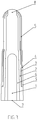
- the ceramic electric heating element has, according to one aspect of the invention, from the inside out, an inner conducting layer, an inner insulating layer, an outer resistive layer, an outer conducting layer, and an outer insulating layer, respectively.
- the inner conducting layer is located in the center of the ceramic electric heating element; the inner insulating layer wraps the inner conducting layer on the outside, and the inner insulating layer is divided into two segments, with the peripheral profile of the lower segment being greater than that of the upper segment; the outer resistive layer wraps the upper part of the inner insulating layer on the outside, and the outer resistive layer is divided into two segments, with the peripheral profile of the lower segment being less than that of the upper segment, and the peripheral profile of the upper segment of the outer resistive layer being less than that of the lower segment of the inner insulating layer; the outer conducting layer wraps the lower segment of the outer resistive layer on the outside, and the outer conducting layer is divided into two segments, with the peripheral profile of the lower segment equaling to that of the lower segment of the inner insulating layer, and the peripheral profile of the upper segment equaling to that of the upper segment of the outer resistive layer; the outer insulating layer wraps the upper segment of the outer conducting layer and the upper segment of the
- the ceramic electric heating element has six layers.
- the ceramic electric heating element has, from the inside out, an inner conducting layer, an inner resistive layer, an inner insulating layer, an outer resistive layer, an outer conducting layer and an outer insulating layer.
- the inner conducting layer is located in the center of the ceramic electric heating element; the inner resistive layer wraps the inner conducting layer on the outside; the inner insulating layer wraps the inner resistive layer on the outside, and the inner insulating layer is divided into two segments, with the peripheral profile of the lower segment being greater than that of the upper segment; the outer resistive layer wraps the upper part of the inner insulating layer on the outside, and the outer resistive layer is divided into two segments, with the peripheral profile of the lower segment being less than that of the upper segment, and the peripheral profile of the upper segment of the outer resistive layer being less than that of the lower segment of the inner insulating layer; the outer conducting layer wraps the lower segment of the outer resistive layer on the outside, and the outer conducting layer is divided into two segments, with the peripheral profile of the lower segment equaling to that of the lower segment of the inner insulating layer, and the peripheral profile of the upper segment equaling to that of the upper segment of the outer resist
- the ceramic electric heating element has four layers, according to another aspect of the invention . Such an arrangement can also save material and reduce cost.
- the ceramic electric heating element has, from the inside out, an inner conducting layer, an inner insulating layer, a resistive layer and an outer insulating layer.
- the inner conducting layer is located in the center of the ceramic electric heating element; the inner insulating layer wraps the inner conducting layer on the outside, and the inner insulating layer is divided into two segments, with the peripheral profile of the lower segment being greater than that of the upper segment; the resistive layer wraps the upper part of the inner insulating layer on the outside, and the resistive layer is divided into two segments, with the peripheral profile of the upper segment being less than that of the lower segment, and the peripheral profile of the lower segment of the resistive layer equaling to that of the lower segment of the inner insulating layer; the outer insulating layer wraps the upper segment of the resistive layer on the outside, with the peripheral profile of the outer insulating layer equaling to that of the lower segment of the resistive layer; and the lower part of the inner conducting layer is a spot where a central electrode is located, the upper end of the resistive layer has a connecting hole, and the outside of the lower part of the resistive layer is a spot where a side
- the spot where the central electrode is located is solid.
- there is a V-type socket at the central electrode and an electrically conductive ceramic electrode is then plugged into the V-type socket.
- the electrically conductive ceramic electrode will generate heat and swell, resulting in formation of microcracks in the ceramic electric heating element and in the end reducing the service life thereof.
- a weld zone of the central electrode inside will be damaged, causing the product to fracture, and effecting the service life thereof.
- the arrangement of the central electrode as a solid and then welding the electrically conductive ceramic electrode to the spot where the central electrode is located can prevent formation of microcracks in the ceramic electric heating element resulting from heat generation and swelling of the electrically conductive ceramic electrode; prevent damage to the inside of the ceramic body, thereby improving service life of the ceramic electric heating element; and eliminate damage to the inside of the ceramic body in the welding process and reduce surface defects of the electric heating element.
- the ceramic electric heating element is a cylinder or a flat-shaped body. Such an arrangement can allow the ceramic electric heating element to have a simplified process during production and a simple structure.
Landscapes
- Engineering & Computer Science (AREA)
- Chemical & Material Sciences (AREA)
- Ceramic Engineering (AREA)
- Inorganic Chemistry (AREA)
- Combustion & Propulsion (AREA)
- Mechanical Engineering (AREA)
- General Engineering & Computer Science (AREA)
- Resistance Heating (AREA)
- Surface Heating Bodies (AREA)
Claims (4)
- Keramisches elektrisches Heizelement, wobei das keramische elektrische Heizelement von einer Isolierschicht umhüllt ist, wobei das keramische elektrische Heizelement von innen nach außen sechs Schichten aufweist, nämlich eine innere leitende Schicht (1), eine innere Widerstandsschicht (6), eine innere Isolierschicht (2), eine äußere Widerstandsschicht (3), eine äußere leitende Schicht (4) bzw. eine äußere Isolierschicht (5), wobei die innere leitende Schicht (1) in der Mitte des keramischen elektrischen Heizelements angeordnet ist; die innere Widerstandsschicht (6) die innere leitende Schicht (1) auf der Außenseite umhüllt; die innere Isolierschicht (2) die innere Widerstandsschicht (6) auf der Außenseite umhüllt, und die innere Isolierschicht (2) in zwei Segmente unterteilt ist, wobei das Umfangsprofil des unteren Segments größer als das des oberen Segments ist; die äußere Widerstandsschicht (3) umhüllt den oberen Teil der inneren Isolierschicht (2) auf der Außenseite, wobei die äußere Isolierschicht (5) das obere Segment der äußeren Widerstandsschicht (3) auf der Außenseite umhüllt, wobei der untere Teil der inneren Leitungsschicht (1) ein Punkt (7) ist, an dem eine Zentralelektrode angeordnet ist, wobei das obere Ende der inneren Widerstandsschicht (6) ein Verbindungsloch (8) aufweist, dadurch gekennzeichnet, dass die äußere leitende Schicht (4) in zwei Segmente unterteilt ist, wobei das Umfangsprofil des unteren Segments dem des unteren Segments der inneren Isolierschicht (2) entspricht und das Umfangsprofil des oberen Segments dem des oberen Segments der äußeren Widerstandsschicht (6) entspricht; und die äußere Isolierschicht (5) das obere Segment der äußeren Leitungsschicht (4) auf der Außenseite umhüllt, wobei das Umfangsprofil der äußeren Isolierschicht (5) dem des unteren Segments der äußeren Leitungsschicht (4) gleich ist; und
die Außenseite des unteren Teils der äußeren leitenden Schicht (4) ist ein Punkt (9), an dem eine Seitenelektrode angeschlossen werden kann,
wobei das Umfangsprofil des unteren Segments der äußeren Widerstandsschicht (3) geringer ist als das des oberen Segments der äußeren Widerstandsschicht (3) und das Umfangsprofil des oberen Segments der äußeren Widerstandsschicht (3) geringer ist als das des unteren Segments der inneren Isolierschicht (2). - Keramisches elektrisches Heizelement, wobei das keramische elektrische Heizelement von einer Isolierschicht umhüllt ist, wobei das keramische elektrische Heizelement von innen nach außen vier Schichten aufweist, nämlich eine innere leitende Schicht (1), eine innere Isolierschicht (2), eine Widerstandsschicht (11) und eine äußere Isolierschicht (5), wobei die innere leitende Schicht (1) in der Mitte des keramischen elektrischen Heizelements angeordnet ist; die innere Isolierschicht (2) die innere leitende Schicht (1) an der Außenseite umhüllt und die innere Isolierschicht (2) in zwei Segmente unterteilt ist, wobei das Umfangsprofil des unteren Segments größer als das des oberen Segments ist; die Widerstandsschicht (11) den oberen Teil der inneren Isolierschicht (2) auf der Außenseite umhüllt und die Widerstandsschicht (11) in zwei Segmente unterteilt ist, wobei das Umfangsprofil des oberen Segments kleiner als das des unteren Segments ist und die äußere Isolierschicht (5) das obere Segment der Widerstandsschicht (11) auf der Außenseite umhüllt; und
der untere Teil der inneren leitenden Schicht (1) ein Punkt (7) ist, an dem sich eine zentrale Elektrode befindet, das obere Ende der inneren Widerstandsschicht (11) ein Verbindungsloch (8) aufweist,
dadurch gekennzeichnet, dass
das Umfangsprofil des unteren Segments der Widerstandsschicht (11) dem des unteren Segments der inneren Isolierschicht (2) entspricht;
das Umfangsprofil der äußeren Isolierschicht (5) gleich dem des unteren Segments der Widerstandsschicht (11) ist,
und die Außenseite des unteren Teils der Widerstandsschicht (11) ist ein Punkt (9), an dem eine Seitenelektrode angeschlossen werden kann. - Keramische elektrische Heizelement nach Anspruch 1 oder 2, wobei der Punkt (7), an dem sich die Mittelelektrode befindet, fest ist.
- Keramisches elektrisches Heizelement nach einem der Ansprüche 1 bis 3, wobei das keramische elektrische Heizelement ein Zylinder oder ein flacher Körper ist.
Applications Claiming Priority (2)
| Application Number | Priority Date | Filing Date | Title |
|---|---|---|---|
| CN201510518736.2A CN105072718B (zh) | 2015-08-21 | 2015-08-21 | 一种陶瓷电热体 |
| PCT/CN2016/095420 WO2017032234A1 (zh) | 2015-08-21 | 2016-08-16 | 一种陶瓷电热体 |
Publications (3)
| Publication Number | Publication Date |
|---|---|
| EP3340736A1 EP3340736A1 (de) | 2018-06-27 |
| EP3340736A4 EP3340736A4 (de) | 2019-05-08 |
| EP3340736B1 true EP3340736B1 (de) | 2020-06-03 |
Family
ID=54501956
Family Applications (1)
| Application Number | Title | Priority Date | Filing Date |
|---|---|---|---|
| EP16838493.1A Active EP3340736B1 (de) | 2015-08-21 | 2016-08-16 | Keramisches elektrisches heizelement |
Country Status (7)
| Country | Link |
|---|---|
| US (2) | US10993288B2 (de) |
| EP (1) | EP3340736B1 (de) |
| JP (1) | JP6941609B2 (de) |
| KR (1) | KR102600151B1 (de) |
| CN (2) | CN106912120A (de) |
| CA (1) | CA2974217C (de) |
| WO (1) | WO2017032234A1 (de) |
Families Citing this family (4)
| Publication number | Priority date | Publication date | Assignee | Title |
|---|---|---|---|---|
| CN106912120A (zh) | 2015-08-21 | 2017-06-30 | 重庆利迈陶瓷技术有限公司 | 一种陶瓷电热体 |
| CN110536491B (zh) | 2019-09-25 | 2024-07-05 | 重庆利迈科技有限公司 | 一种两层结构的陶瓷电热体及电烙铁 |
| CN114679801A (zh) * | 2022-03-30 | 2022-06-28 | 重庆利迈科技有限公司 | 一种全陶瓷发热体 |
| CN116669238A (zh) * | 2023-03-13 | 2023-08-29 | 重庆利迈科技有限公司 | 一种方块型陶瓷电热体 |
Family Cites Families (52)
| Publication number | Priority date | Publication date | Assignee | Title |
|---|---|---|---|---|
| US1927562A (en) | 1930-01-31 | 1933-09-19 | Packard Motor Car Co | Glow plug |
| US1950457A (en) | 1933-05-25 | 1934-03-13 | B G Corp | Series glow-plug |
| US2127983A (en) | 1936-10-01 | 1938-08-23 | Eclipse Aviat Corp | Combustion control for internal combustion engines |
| DE1297785B (de) | 1964-04-30 | 1969-06-19 | Eltra Kg Leicht & Trambauer | Wasserdichter elektrischer Anschluss fuer elektrische Rohrheizkoerper und Verfahren zu seiner Herstellung |
| US4437440A (en) | 1979-06-20 | 1984-03-20 | Ngk Spark Plug Co., Ltd. | Auxiliary combustion chamber preheating device |
| US4418661A (en) | 1981-02-07 | 1983-12-06 | Robert Bosch Gmbh | Glow plug, particularly for diesel engine |
| US4475029A (en) | 1982-03-02 | 1984-10-02 | Nippondenso Co., Ltd. | Ceramic heater |
| JPS58166252A (ja) | 1982-03-26 | 1983-10-01 | Toyota Motor Corp | セラミツクヒ−タ付酸素センサ素子及びその製造方法 |
| DE3318458A1 (de) | 1983-05-20 | 1984-11-22 | Robert Bosch Gmbh, 7000 Stuttgart | Gluehkerze fuer brennkraftmaschinen |
| US4816643A (en) | 1985-03-15 | 1989-03-28 | Allied-Signal Inc. | Glow plug having a metal silicide resistive film heater |
| JPS62731A (ja) | 1985-06-27 | 1987-01-06 | Jidosha Kiki Co Ltd | デイ−ゼルエンジン用グロ−プラグ |
| JPS62175523A (ja) * | 1986-01-27 | 1987-08-01 | Jidosha Kiki Co Ltd | デイ−ゼルエンジン用グロ−プラグ |
| JPS6361662U (de) | 1986-10-09 | 1988-04-23 | ||
| US4901196A (en) | 1988-05-16 | 1990-02-13 | Grzybowski John D | Portable barbeque lighter |
| DE8815005U1 (de) | 1988-12-02 | 1990-03-29 | Robert Bosch Gmbh, 7000 Stuttgart | Glühkerze für Brennkraftmaschinen |
| US5084607A (en) | 1989-07-28 | 1992-01-28 | Caterpillar Inc. | Interference connection between a heating element and body of a glow plug |
| US5084606A (en) | 1990-05-17 | 1992-01-28 | Caterpillar Inc. | Encapsulated heating filament for glow plug |
| US5075536A (en) | 1990-05-17 | 1991-12-24 | Caterpillar Inc. | Heating element assembly for glow plug |
| US5304778A (en) | 1992-11-23 | 1994-04-19 | Electrofuel Manufacturing Co. | Glow plug with improved composite sintered silicon nitride ceramic heater |
| DE69425308D1 (de) | 1993-10-04 | 2000-08-24 | Isuzu Ceramics Res Inst | Keramische Glühkerze |
| US5367994A (en) | 1993-10-15 | 1994-11-29 | Detroit Diesel Corporation | Method of operating a diesel engine utilizing a continuously powered glow plug |
| DE4335292A1 (de) | 1993-10-15 | 1995-04-20 | Beru Werk Ruprecht Gmbh Co A | Glühkerze |
| JP3814873B2 (ja) * | 1996-06-26 | 2006-08-30 | 株式会社デンソー | イオン電流検出装置 |
| US5880432A (en) | 1996-12-23 | 1999-03-09 | Le-Mark International Ltd. | Electric heating device with ceramic heater wedgingly received within a metalic body |
| JP3784124B2 (ja) * | 1997-02-28 | 2006-06-07 | 京セラ株式会社 | セラミックシーズヒータ及びこれを用いた流体加熱装置 |
| US5993722A (en) | 1997-06-25 | 1999-11-30 | Le-Mark International Ltd. | Method for making ceramic heater having reduced internal stress |
| CN2319991Y (zh) * | 1998-01-25 | 1999-05-19 | 雷彼得 | 一种柴油机电热塞的圆锥形全陶瓷加热芯 |
| CN2324746Y (zh) * | 1998-01-25 | 1999-06-16 | 雷彼得 | 一种柴油机全陶瓷电热塞 |
| CN2368247Y (zh) * | 1999-04-16 | 2000-03-08 | 高海勇 | 一种电加热器的加热芯 |
| US6884967B1 (en) * | 1999-06-16 | 2005-04-26 | Chongging Le-Mark Ceramic Technology Co. Ltd. | Multi-layer ceramic heater element and method of making same |
| WO2002003759A1 (en) * | 2000-07-03 | 2002-01-10 | Le-Mark Patent International Limited | Multi-layer ceramic heater element and method of making same |
| US6184497B1 (en) * | 1999-06-16 | 2001-02-06 | Le-Mark International Ltd. | Multi-layer ceramic heater element and method of making same |
| US6084212A (en) | 1999-06-16 | 2000-07-04 | Le-Mark International Ltd | Multi-layer ceramic heater element and method of making same |
| CN2393295Y (zh) * | 1999-09-20 | 2000-08-23 | 雷彼得 | 有外导电层的五层结构全陶瓷电热体 |
| CN2415573Y (zh) * | 2000-01-18 | 2001-01-17 | 雷彼得 | 有外导电层的四层结构全陶瓷电热体 |
| US6610964B2 (en) * | 2001-03-08 | 2003-08-26 | Stephen J. Radmacher | Multi-layer ceramic heater |
| US6396028B1 (en) * | 2001-03-08 | 2002-05-28 | Stephen J. Radmacher | Multi-layer ceramic heater |
| CN2508511Y (zh) * | 2001-08-23 | 2002-08-28 | 吴仕式 | 封闭式塔形陶瓷电热组件 |
| CN2537193Y (zh) * | 2002-03-28 | 2003-02-19 | 雷彼得 | 热流体管道全陶瓷电热体加温器 |
| JP4425017B2 (ja) * | 2003-04-07 | 2010-03-03 | 日本特殊陶業株式会社 | ヒータ |
| KR100915576B1 (ko) * | 2004-05-27 | 2009-09-07 | 쿄세라 코포레이션 | 세라믹 히터 및 그것을 사용한 글로우 플러그 |
| CN2775985Y (zh) * | 2005-04-06 | 2006-04-26 | 陈伟良 | 陶瓷发热器 |
| US7607206B2 (en) * | 2005-12-29 | 2009-10-27 | Federal Mogul World Wide, Inc. | Method for forming layered heating element for glow plug |
| CN100496169C (zh) * | 2006-03-04 | 2009-06-03 | 雷彼得 | 六层结构全陶瓷电热体 |
| CN100496168C (zh) * | 2006-08-24 | 2009-06-03 | 雷彼得 | 有中心孔的全陶瓷电热体 |
| CN101945506A (zh) * | 2010-08-17 | 2011-01-12 | 钟秉霖 | 一种瓷能发热体 |
| US9668302B2 (en) | 2011-03-31 | 2017-05-30 | Kyocera Corporation | Ceramic heater |
| CN102705131A (zh) * | 2012-05-09 | 2012-10-03 | 扬州市飞鹰电子科技有限公司 | 柴油发动机陶瓷电热塞 |
| JP3183899U (ja) * | 2013-03-25 | 2013-06-06 | 秦文隆 | 加熱器 |
| JP5795029B2 (ja) * | 2013-07-09 | 2015-10-14 | 日本特殊陶業株式会社 | セラミックヒータ、グロープラグ、セラミックヒータの製造方法、および、グロープラグの製造方法 |
| CN205179394U (zh) * | 2015-08-21 | 2016-04-20 | 雷彼得 | 一种陶瓷电热体 |
| CN106912120A (zh) * | 2015-08-21 | 2017-06-30 | 重庆利迈陶瓷技术有限公司 | 一种陶瓷电热体 |
-
2015
- 2015-08-21 CN CN201710319474.6A patent/CN106912120A/zh active Pending
- 2015-08-21 CN CN201510518736.2A patent/CN105072718B/zh active Active
-
2016
- 2016-08-16 KR KR1020177033208A patent/KR102600151B1/ko active Active
- 2016-08-16 JP JP2018528371A patent/JP6941609B2/ja active Active
- 2016-08-16 US US15/550,756 patent/US10993288B2/en active Active
- 2016-08-16 EP EP16838493.1A patent/EP3340736B1/de active Active
- 2016-08-16 CA CA2974217A patent/CA2974217C/en active Active
- 2016-08-16 WO PCT/CN2016/095420 patent/WO2017032234A1/zh not_active Ceased
-
2021
- 2021-03-23 US US17/209,643 patent/US11930564B2/en active Active
Non-Patent Citations (1)
| Title |
|---|
| None * |
Also Published As
| Publication number | Publication date |
|---|---|
| EP3340736A4 (de) | 2019-05-08 |
| WO2017032234A1 (zh) | 2017-03-02 |
| KR102600151B1 (ko) | 2023-11-07 |
| CN106912120A (zh) | 2017-06-30 |
| HK1251396A1 (en) | 2019-01-25 |
| CA2974217A1 (en) | 2017-03-02 |
| US10993288B2 (en) | 2021-04-27 |
| CN105072718A (zh) | 2015-11-18 |
| JP2018523908A (ja) | 2018-08-23 |
| CN105072718B (zh) | 2017-06-16 |
| US11930564B2 (en) | 2024-03-12 |
| KR20180041620A (ko) | 2018-04-24 |
| US20180176992A1 (en) | 2018-06-21 |
| JP6941609B2 (ja) | 2021-09-29 |
| EP3340736A1 (de) | 2018-06-27 |
| CA2974217C (en) | 2023-06-27 |
| US20210212171A1 (en) | 2021-07-08 |
Similar Documents
| Publication | Publication Date | Title |
|---|---|---|
| US11930564B2 (en) | Ceramic electric heating element | |
| JP2012516545A5 (de) | ||
| CN202103870U (zh) | 一种石墨棒加热体的连接结构 | |
| CN203351805U (zh) | 一种窗口式电缆连接器 | |
| HK1251396B (en) | Ceramic electric heating element | |
| CN208922972U (zh) | 一种新型真空管 | |
| CN201871868U (zh) | 一种钢塑复合管道焊接装置 | |
| CN103367022B (zh) | 气体绝缘负荷开关灭弧线圈 | |
| CN202667892U (zh) | 焊枪用导电嘴 | |
| CN201478124U (zh) | 电容器的芯子结构 | |
| CN201455502U (zh) | 缝焊机 | |
| CN201383475Y (zh) | 跌落式熔断器 | |
| CN223142157U (zh) | 一种便于连接的陶瓷发热棒 | |
| CN212625362U (zh) | 一种有效防止开裂的真空灭弧室屏蔽筒 | |
| CN221863107U (zh) | 一种针型发热器 | |
| CN219780427U (zh) | 一种单头电热管 | |
| CN203761593U (zh) | 一种新型电热管 | |
| CN204927220U (zh) | 一种保险丝管 | |
| CN2415573Y (zh) | 有外导电层的四层结构全陶瓷电热体 | |
| CN204069383U (zh) | 电热吹风管 | |
| CN103117526A (zh) | 一种高压电缆接线装置 | |
| CN203607671U (zh) | 多间隙火花塞 | |
| CN209578458U (zh) | 凸焊电极及凸焊机 | |
| CN207611730U (zh) | 一种静触头 | |
| CN207246561U (zh) | 一种抱箍 |
Legal Events
| Date | Code | Title | Description |
|---|---|---|---|
| STAA | Information on the status of an ep patent application or granted ep patent |
Free format text: STATUS: THE INTERNATIONAL PUBLICATION HAS BEEN MADE |
|
| PUAI | Public reference made under article 153(3) epc to a published international application that has entered the european phase |
Free format text: ORIGINAL CODE: 0009012 |
|
| STAA | Information on the status of an ep patent application or granted ep patent |
Free format text: STATUS: REQUEST FOR EXAMINATION WAS MADE |
|
| 17P | Request for examination filed |
Effective date: 20170721 |
|
| AK | Designated contracting states |
Kind code of ref document: A1 Designated state(s): AL AT BE BG CH CY CZ DE DK EE ES FI FR GB GR HR HU IE IS IT LI LT LU LV MC MK MT NL NO PL PT RO RS SE SI SK SM TR |
|
| AX | Request for extension of the european patent |
Extension state: BA ME |
|
| DAV | Request for validation of the european patent (deleted) | ||
| DAX | Request for extension of the european patent (deleted) | ||
| REG | Reference to a national code |
Ref country code: HK Ref legal event code: DE Ref document number: 1251396 Country of ref document: HK |
|
| A4 | Supplementary search report drawn up and despatched |
Effective date: 20190409 |
|
| RIC1 | Information provided on ipc code assigned before grant |
Ipc: H05B 3/18 20060101ALI20190403BHEP Ipc: H05B 3/28 20060101AFI20190403BHEP |
|
| GRAP | Despatch of communication of intention to grant a patent |
Free format text: ORIGINAL CODE: EPIDOSNIGR1 |
|
| STAA | Information on the status of an ep patent application or granted ep patent |
Free format text: STATUS: GRANT OF PATENT IS INTENDED |
|
| INTG | Intention to grant announced |
Effective date: 20200128 |
|
| GRAS | Grant fee paid |
Free format text: ORIGINAL CODE: EPIDOSNIGR3 |
|
| GRAA | (expected) grant |
Free format text: ORIGINAL CODE: 0009210 |
|
| STAA | Information on the status of an ep patent application or granted ep patent |
Free format text: STATUS: THE PATENT HAS BEEN GRANTED |
|
| AK | Designated contracting states |
Kind code of ref document: B1 Designated state(s): AL AT BE BG CH CY CZ DE DK EE ES FI FR GB GR HR HU IE IS IT LI LT LU LV MC MK MT NL NO PL PT RO RS SE SI SK SM TR |
|
| REG | Reference to a national code |
Ref country code: GB Ref legal event code: FG4D |
|
| REG | Reference to a national code |
Ref country code: AT Ref legal event code: REF Ref document number: 1278453 Country of ref document: AT Kind code of ref document: T Effective date: 20200615 Ref country code: CH Ref legal event code: EP |
|
| REG | Reference to a national code |
Ref country code: DE Ref legal event code: R096 Ref document number: 602016037671 Country of ref document: DE |
|
| REG | Reference to a national code |
Ref country code: NL Ref legal event code: FP |
|
| REG | Reference to a national code |
Ref country code: LT Ref legal event code: MG4D |
|
| PG25 | Lapsed in a contracting state [announced via postgrant information from national office to epo] |
Ref country code: LT Free format text: LAPSE BECAUSE OF FAILURE TO SUBMIT A TRANSLATION OF THE DESCRIPTION OR TO PAY THE FEE WITHIN THE PRESCRIBED TIME-LIMIT Effective date: 20200603 Ref country code: SE Free format text: LAPSE BECAUSE OF FAILURE TO SUBMIT A TRANSLATION OF THE DESCRIPTION OR TO PAY THE FEE WITHIN THE PRESCRIBED TIME-LIMIT Effective date: 20200603 Ref country code: NO Free format text: LAPSE BECAUSE OF FAILURE TO SUBMIT A TRANSLATION OF THE DESCRIPTION OR TO PAY THE FEE WITHIN THE PRESCRIBED TIME-LIMIT Effective date: 20200903 Ref country code: GR Free format text: LAPSE BECAUSE OF FAILURE TO SUBMIT A TRANSLATION OF THE DESCRIPTION OR TO PAY THE FEE WITHIN THE PRESCRIBED TIME-LIMIT Effective date: 20200904 Ref country code: FI Free format text: LAPSE BECAUSE OF FAILURE TO SUBMIT A TRANSLATION OF THE DESCRIPTION OR TO PAY THE FEE WITHIN THE PRESCRIBED TIME-LIMIT Effective date: 20200603 |
|
| PG25 | Lapsed in a contracting state [announced via postgrant information from national office to epo] |
Ref country code: RS Free format text: LAPSE BECAUSE OF FAILURE TO SUBMIT A TRANSLATION OF THE DESCRIPTION OR TO PAY THE FEE WITHIN THE PRESCRIBED TIME-LIMIT Effective date: 20200603 Ref country code: HR Free format text: LAPSE BECAUSE OF FAILURE TO SUBMIT A TRANSLATION OF THE DESCRIPTION OR TO PAY THE FEE WITHIN THE PRESCRIBED TIME-LIMIT Effective date: 20200603 Ref country code: LV Free format text: LAPSE BECAUSE OF FAILURE TO SUBMIT A TRANSLATION OF THE DESCRIPTION OR TO PAY THE FEE WITHIN THE PRESCRIBED TIME-LIMIT Effective date: 20200603 Ref country code: BG Free format text: LAPSE BECAUSE OF FAILURE TO SUBMIT A TRANSLATION OF THE DESCRIPTION OR TO PAY THE FEE WITHIN THE PRESCRIBED TIME-LIMIT Effective date: 20200903 |
|
| REG | Reference to a national code |
Ref country code: AT Ref legal event code: MK05 Ref document number: 1278453 Country of ref document: AT Kind code of ref document: T Effective date: 20200603 |
|
| PG25 | Lapsed in a contracting state [announced via postgrant information from national office to epo] |
Ref country code: AL Free format text: LAPSE BECAUSE OF FAILURE TO SUBMIT A TRANSLATION OF THE DESCRIPTION OR TO PAY THE FEE WITHIN THE PRESCRIBED TIME-LIMIT Effective date: 20200603 |
|
| PG25 | Lapsed in a contracting state [announced via postgrant information from national office to epo] |
Ref country code: CZ Free format text: LAPSE BECAUSE OF FAILURE TO SUBMIT A TRANSLATION OF THE DESCRIPTION OR TO PAY THE FEE WITHIN THE PRESCRIBED TIME-LIMIT Effective date: 20200603 Ref country code: ES Free format text: LAPSE BECAUSE OF FAILURE TO SUBMIT A TRANSLATION OF THE DESCRIPTION OR TO PAY THE FEE WITHIN THE PRESCRIBED TIME-LIMIT Effective date: 20200603 Ref country code: RO Free format text: LAPSE BECAUSE OF FAILURE TO SUBMIT A TRANSLATION OF THE DESCRIPTION OR TO PAY THE FEE WITHIN THE PRESCRIBED TIME-LIMIT Effective date: 20200603 Ref country code: PT Free format text: LAPSE BECAUSE OF FAILURE TO SUBMIT A TRANSLATION OF THE DESCRIPTION OR TO PAY THE FEE WITHIN THE PRESCRIBED TIME-LIMIT Effective date: 20201006 Ref country code: SM Free format text: LAPSE BECAUSE OF FAILURE TO SUBMIT A TRANSLATION OF THE DESCRIPTION OR TO PAY THE FEE WITHIN THE PRESCRIBED TIME-LIMIT Effective date: 20200603 Ref country code: EE Free format text: LAPSE BECAUSE OF FAILURE TO SUBMIT A TRANSLATION OF THE DESCRIPTION OR TO PAY THE FEE WITHIN THE PRESCRIBED TIME-LIMIT Effective date: 20200603 Ref country code: AT Free format text: LAPSE BECAUSE OF FAILURE TO SUBMIT A TRANSLATION OF THE DESCRIPTION OR TO PAY THE FEE WITHIN THE PRESCRIBED TIME-LIMIT Effective date: 20200603 |
|
| PG25 | Lapsed in a contracting state [announced via postgrant information from national office to epo] |
Ref country code: IS Free format text: LAPSE BECAUSE OF FAILURE TO SUBMIT A TRANSLATION OF THE DESCRIPTION OR TO PAY THE FEE WITHIN THE PRESCRIBED TIME-LIMIT Effective date: 20201003 Ref country code: SK Free format text: LAPSE BECAUSE OF FAILURE TO SUBMIT A TRANSLATION OF THE DESCRIPTION OR TO PAY THE FEE WITHIN THE PRESCRIBED TIME-LIMIT Effective date: 20200603 Ref country code: PL Free format text: LAPSE BECAUSE OF FAILURE TO SUBMIT A TRANSLATION OF THE DESCRIPTION OR TO PAY THE FEE WITHIN THE PRESCRIBED TIME-LIMIT Effective date: 20200603 |
|
| REG | Reference to a national code |
Ref country code: DE Ref legal event code: R097 Ref document number: 602016037671 Country of ref document: DE |
|
| PG25 | Lapsed in a contracting state [announced via postgrant information from national office to epo] |
Ref country code: MC Free format text: LAPSE BECAUSE OF FAILURE TO SUBMIT A TRANSLATION OF THE DESCRIPTION OR TO PAY THE FEE WITHIN THE PRESCRIBED TIME-LIMIT Effective date: 20200603 |
|
| REG | Reference to a national code |
Ref country code: CH Ref legal event code: PL |
|
| PLBE | No opposition filed within time limit |
Free format text: ORIGINAL CODE: 0009261 |
|
| STAA | Information on the status of an ep patent application or granted ep patent |
Free format text: STATUS: NO OPPOSITION FILED WITHIN TIME LIMIT |
|
| PG25 | Lapsed in a contracting state [announced via postgrant information from national office to epo] |
Ref country code: LI Free format text: LAPSE BECAUSE OF NON-PAYMENT OF DUE FEES Effective date: 20200831 Ref country code: LU Free format text: LAPSE BECAUSE OF NON-PAYMENT OF DUE FEES Effective date: 20200816 Ref country code: DK Free format text: LAPSE BECAUSE OF FAILURE TO SUBMIT A TRANSLATION OF THE DESCRIPTION OR TO PAY THE FEE WITHIN THE PRESCRIBED TIME-LIMIT Effective date: 20200603 Ref country code: CH Free format text: LAPSE BECAUSE OF NON-PAYMENT OF DUE FEES Effective date: 20200831 |
|
| 26N | No opposition filed |
Effective date: 20210304 |
|
| REG | Reference to a national code |
Ref country code: BE Ref legal event code: MM Effective date: 20200831 |
|
| PG25 | Lapsed in a contracting state [announced via postgrant information from national office to epo] |
Ref country code: SI Free format text: LAPSE BECAUSE OF FAILURE TO SUBMIT A TRANSLATION OF THE DESCRIPTION OR TO PAY THE FEE WITHIN THE PRESCRIBED TIME-LIMIT Effective date: 20200603 |
|
| PG25 | Lapsed in a contracting state [announced via postgrant information from national office to epo] |
Ref country code: IE Free format text: LAPSE BECAUSE OF NON-PAYMENT OF DUE FEES Effective date: 20200816 Ref country code: BE Free format text: LAPSE BECAUSE OF NON-PAYMENT OF DUE FEES Effective date: 20200831 |
|
| PG25 | Lapsed in a contracting state [announced via postgrant information from national office to epo] |
Ref country code: TR Free format text: LAPSE BECAUSE OF FAILURE TO SUBMIT A TRANSLATION OF THE DESCRIPTION OR TO PAY THE FEE WITHIN THE PRESCRIBED TIME-LIMIT Effective date: 20200603 Ref country code: MT Free format text: LAPSE BECAUSE OF FAILURE TO SUBMIT A TRANSLATION OF THE DESCRIPTION OR TO PAY THE FEE WITHIN THE PRESCRIBED TIME-LIMIT Effective date: 20200603 Ref country code: CY Free format text: LAPSE BECAUSE OF FAILURE TO SUBMIT A TRANSLATION OF THE DESCRIPTION OR TO PAY THE FEE WITHIN THE PRESCRIBED TIME-LIMIT Effective date: 20200603 |
|
| REG | Reference to a national code |
Ref country code: DE Ref legal event code: R081 Ref document number: 602016037671 Country of ref document: DE Owner name: CHONGQING LE-MARK TECHNOLOGY CO., LTD., CN Free format text: FORMER OWNER: CHONGQING LE-MARK CERAMIC TECHNOLOGY CO., LTD., CHONGQING, CN |
|
| REG | Reference to a national code |
Ref country code: NL Ref legal event code: HC Owner name: CHONGQING LE-MARK TECHNOLOGY CO., LTD.; CN Free format text: DETAILS ASSIGNMENT: CHANGE OF OWNER(S), CHANGE OF OWNER(S) NAME; FORMER OWNER NAME: CHONGQING LE-MARK CERAMIC TECHNOLOGY CO., LTD. Effective date: 20220620 |
|
| PG25 | Lapsed in a contracting state [announced via postgrant information from national office to epo] |
Ref country code: MK Free format text: LAPSE BECAUSE OF FAILURE TO SUBMIT A TRANSLATION OF THE DESCRIPTION OR TO PAY THE FEE WITHIN THE PRESCRIBED TIME-LIMIT Effective date: 20200603 |
|
| P01 | Opt-out of the competence of the unified patent court (upc) registered |
Effective date: 20230419 |
|
| PGFP | Annual fee paid to national office [announced via postgrant information from national office to epo] |
Ref country code: GB Payment date: 20250626 Year of fee payment: 10 |
|
| PGFP | Annual fee paid to national office [announced via postgrant information from national office to epo] |
Ref country code: NL Payment date: 20250613 Year of fee payment: 10 |
|
| PGFP | Annual fee paid to national office [announced via postgrant information from national office to epo] |
Ref country code: FR Payment date: 20250610 Year of fee payment: 10 |
|
| PGFP | Annual fee paid to national office [announced via postgrant information from national office to epo] |
Ref country code: DE Payment date: 20250624 Year of fee payment: 10 |
|
| PGFP | Annual fee paid to national office [announced via postgrant information from national office to epo] |
Ref country code: IT Payment date: 20250722 Year of fee payment: 10 |