EP3326274B1 - Method and apparatus for inserting undulated coil assemblies in the slots of cores of dynamoelectric machines - Google Patents
Method and apparatus for inserting undulated coil assemblies in the slots of cores of dynamoelectric machines Download PDFInfo
- Publication number
- EP3326274B1 EP3326274B1 EP16753473.4A EP16753473A EP3326274B1 EP 3326274 B1 EP3326274 B1 EP 3326274B1 EP 16753473 A EP16753473 A EP 16753473A EP 3326274 B1 EP3326274 B1 EP 3326274B1
- Authority
- EP
- European Patent Office
- Prior art keywords
- slots
- linear portions
- support member
- coil portion
- guide
- Prior art date
- Legal status (The legal status is an assumption and is not a legal conclusion. Google has not performed a legal analysis and makes no representation as to the accuracy of the status listed.)
- Active
Links
Images

Classifications
-
- H—ELECTRICITY
- H02—GENERATION; CONVERSION OR DISTRIBUTION OF ELECTRIC POWER
- H02K—DYNAMO-ELECTRIC MACHINES
- H02K15/00—Processes or apparatus specially adapted for manufacturing, assembling, maintaining or repairing of dynamo-electric machines
- H02K15/06—Embedding prefabricated windings in the machines
- H02K15/062—Windings in slots; Salient pole windings
- H02K15/065—Windings consisting of complete sections, e.g. coils or waves
- H02K15/066—Windings consisting of complete sections, e.g. coils or waves inserted perpendicularly to the axis of the slots or inter-polar channels
-
- H—ELECTRICITY
- H02—GENERATION; CONVERSION OR DISTRIBUTION OF ELECTRIC POWER
- H02K—DYNAMO-ELECTRIC MACHINES
- H02K15/00—Processes or apparatus specially adapted for manufacturing, assembling, maintaining or repairing of dynamo-electric machines
- H02K15/02—Processes or apparatus specially adapted for manufacturing, assembling, maintaining or repairing of dynamo-electric machines of stator or rotor bodies
- H02K15/021—Magnetic cores
-
- H—ELECTRICITY
- H02—GENERATION; CONVERSION OR DISTRIBUTION OF ELECTRIC POWER
- H02K—DYNAMO-ELECTRIC MACHINES
- H02K15/00—Processes or apparatus specially adapted for manufacturing, assembling, maintaining or repairing of dynamo-electric machines
- H02K15/04—Processes or apparatus specially adapted for manufacturing, assembling, maintaining or repairing of dynamo-electric machines of windings prior to their mounting into the machines
- H02K15/0414—Processes or apparatus specially adapted for manufacturing, assembling, maintaining or repairing of dynamo-electric machines of windings prior to their mounting into the machines the windings consisting of separate elements, e.g. bars, segments or half coils
- H02K15/0421—Processes or apparatus specially adapted for manufacturing, assembling, maintaining or repairing of dynamo-electric machines of windings prior to their mounting into the machines the windings consisting of separate elements, e.g. bars, segments or half coils and consisting of single conductors, e.g. hairpins
- H02K15/0428—Processes or apparatus for simultaneously twisting two or more hairpins
-
- H—ELECTRICITY
- H02—GENERATION; CONVERSION OR DISTRIBUTION OF ELECTRIC POWER
- H02K—DYNAMO-ELECTRIC MACHINES
- H02K15/00—Processes or apparatus specially adapted for manufacturing, assembling, maintaining or repairing of dynamo-electric machines
- H02K15/06—Embedding prefabricated windings in the machines
- H02K15/062—Windings in slots; Salient pole windings
- H02K15/064—Windings consisting of separate segments
-
- H—ELECTRICITY
- H02—GENERATION; CONVERSION OR DISTRIBUTION OF ELECTRIC POWER
- H02K—DYNAMO-ELECTRIC MACHINES
- H02K3/00—Details of windings
- H02K3/04—Windings characterised by the conductor shape, form or construction, e.g. with bar conductors
- H02K3/12—Windings characterised by the conductor shape, form or construction, e.g. with bar conductors arranged in slots
-
- H—ELECTRICITY
- H02—GENERATION; CONVERSION OR DISTRIBUTION OF ELECTRIC POWER
- H02K—DYNAMO-ELECTRIC MACHINES
- H02K15/00—Processes or apparatus specially adapted for manufacturing, assembling, maintaining or repairing of dynamo-electric machines
- H02K15/04—Processes or apparatus specially adapted for manufacturing, assembling, maintaining or repairing of dynamo-electric machines of windings prior to their mounting into the machines
- H02K15/0414—Processes or apparatus specially adapted for manufacturing, assembling, maintaining or repairing of dynamo-electric machines of windings prior to their mounting into the machines the windings consisting of separate elements, e.g. bars, segments or half coils
- H02K15/0421—Processes or apparatus specially adapted for manufacturing, assembling, maintaining or repairing of dynamo-electric machines of windings prior to their mounting into the machines the windings consisting of separate elements, e.g. bars, segments or half coils and consisting of single conductors, e.g. hairpins
-
- Y—GENERAL TAGGING OF NEW TECHNOLOGICAL DEVELOPMENTS; GENERAL TAGGING OF CROSS-SECTIONAL TECHNOLOGIES SPANNING OVER SEVERAL SECTIONS OF THE IPC; TECHNICAL SUBJECTS COVERED BY FORMER USPC CROSS-REFERENCE ART COLLECTIONS [XRACs] AND DIGESTS
- Y10—TECHNICAL SUBJECTS COVERED BY FORMER USPC
- Y10T—TECHNICAL SUBJECTS COVERED BY FORMER US CLASSIFICATION
- Y10T29/00—Metal working
- Y10T29/49—Method of mechanical manufacture
- Y10T29/49002—Electrical device making
- Y10T29/4902—Electromagnet, transformer or inductor
- Y10T29/49073—Electromagnet, transformer or inductor by assembling coil and core
-
- Y—GENERAL TAGGING OF NEW TECHNOLOGICAL DEVELOPMENTS; GENERAL TAGGING OF CROSS-SECTIONAL TECHNOLOGIES SPANNING OVER SEVERAL SECTIONS OF THE IPC; TECHNICAL SUBJECTS COVERED BY FORMER USPC CROSS-REFERENCE ART COLLECTIONS [XRACs] AND DIGESTS
- Y10—TECHNICAL SUBJECTS COVERED BY FORMER USPC
- Y10T—TECHNICAL SUBJECTS COVERED BY FORMER US CLASSIFICATION
- Y10T29/00—Metal working
- Y10T29/53—Means to assemble or disassemble
- Y10T29/5313—Means to assemble electrical device
- Y10T29/53143—Motor or generator
Definitions
- the present invention relates to a method and apparatus for inserting conductor coils in cores of dynamoelectric cores, particularly stator cores.
- a coil which is inserted, has adjacent linear portions extending parallel to each other, and a plurality of turn portions for connecting the adjacent linear portions with each other.
- the turn portions are alternately at one end side and at another other end side of the linear portions.
- the general form of the coil is normally designated undulated coil, or wave wound coil.
- the linear portions are inserted in slots of a stator core, whilst the turn portions protrude from respective end sides of the stator core.
- the section of the conductor from which the coil is formed may be circular, square or rectangular.
- the size of the section of the conductor is usually comparable to the width of the slot section of the core.
- the cross sections of the conductors present in a slot are normally positioned one adjacent to another in a radial direction of the stator core, i.e. along a radial extension of the core, which extends from a slot entrance to the bottom of the same slot.
- a coil formed from one conductor having the undulated configuration will be referred to as a coil.
- a number of coils having the aforementioned configuration, and which are assembled together will be referred to as a coil assembly.
- a particular case can be that of the coil assembly formed according to a woven configuration.
- the linear portions When examining a conductor of the coil assembly formed according to a woven configuration, the linear portions are positioned alternatively above and below the linear portions of another conductor along the coil assembly. The positioning of this superposition for a same conductor is repeated at a predetermined distance for a certain number of undulations. The turn portions joining these linear portions are positioned to be partially above and partially below turn portions of the other coils.
- a non woven or layered flat coil assembly consists of a certain number of undulated coils each formed from a respective conductor and having a same pitch distance separating the linear portions. Therefore, a layered flat coil assembly consists of a number of single flat coils having linear portions that are adjacent to each other connected by turn portions.
- the single flat coils are layered one on top of the other by superimposing linear portions one on top of the other, although one coil, which is immediately above another coil, will have linear portions shifted by the common pitch distance separating the adjacent linear portions.
- the result is a layered coil assembly having a multiple number of two superimposed linear portions like in the woven configuration, but with the turn portions simply superimposed.
- External leads of the layered assembly can connect one coil to another of the layers in order to achieve a required electric scheme that is equivalent to the scheme of the woven configuration.
- Stator cores wound according to these principles can be used in dynamoelectric machines; in particular to act as traction motors and energy generators for vehicles.
- linear portions of the woven or layered coil assemblies will be superimposed to be seated in a same slot of the core, whilst the turn portions will be partially superimposed according to a certain progression, and remain positioned at the ends of the stator core, outside the slots.
- a traditional principle of inserting the coil assembly is to transfer the flat coil onto a cylindrical arbor, where seats are present for positioning the linear portions in the angular positions matching the angular position where the linear portions need to be inserted.
- Pushing members of the arbor push the linear portions into aligned slots of the core by moving along radial directions corresponding to specific angular positions where the linear portions need to be located in the slots.
- This type of insertion maintains the cross sections of the superimposed linear portions at a constant angle with respect to the radial insertion direction. Accordingly, the orientation of the cross section remains at a zero angle with respect to the radial direction of the core.
- the zero angle requires that pitch distance separating adjacent superimposed linear portions be the same as the angular distance separating the entrance of adjacent slots, otherwise the superimposed linear portions are not aligned with the entrances of the slots, with the consequence that the superimposed linear portions cannot be inserted.
- the superimposed linear portions need to move from an internal diameter circumference corresponding to the slot entrances to a more external diameter circumference corresponding to the final position of the superimposed linear portions.
- the insertion of the superimposed linear portions having the pitch distance equal to the distance separating the entrances has the effect of straining the relative conductors and pulling the turn portions towards the faces of the stator core when the linear portions are moved along the radial distance of the slots.
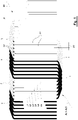
- Coil assembly 90 is a flat coil assembly parallel to the plane P of the drawing of figure 1 .
- the coil assembly 90 of figure 1 can be considered to be an interlacing of coil portions. More particularly, the coil assembly consists of a repetition of areas of six linear portions L1-L6 of coil superimposed on six linear portions AL1-AL6. Consequently two superimposed linear portions are at a pitch distance PT from two adjacent linear portions, as shown in figure 1 .
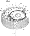
- a stator core 101 which receives the coil assembly of figure 1 is shown in figures 2 and 3 .
- the stator core will have a number of slots 102 proportional to the total number of superimposed linear portions LI. This total includes the linear portions of superimposed initial and final leads.
- two superimposed linear portions LI are accommodated on two other superimposed linear portions LI, which are accommodated on other two superimposed linear portions LI, as shown in figure 7 .
- Two superimposed linear portions are for example like linear portion L1 superimposed on linear portion AL1, or like linear portion L2 superimposed on linear portion AL2 of figure 1 . This will depend on the number of superimposed linear portions LI present in the coil assembly, which has been formed.
- FIG. 7 shows the case where a slot contains 4 pairs of superimposed linear portions LI, which corresponds to 8 conductors present in a slot 102.
- linear portions LI when referred to the object being inserted, will mean two superimposed linear portions, like has been described in the foregoing. These two superimposed linear portions need to be inserted in a same slot 102.
- linear portions LI which are in adjacent slots, will be separated by a pitch distance PT, which is greater than the pitch distance PI which separates the entrances of the slots 102'. In this situation, at least linear portions 50 will not be sufficiently aligned with the entrance of slot 102', and therefore will not be able to enter slot 102'.
- Figure 6 shows instances of insertion of adjacent linear portions according to the principles of the invention.
- the adjacent linear portions have been rotated by angles A and B with respect to the radial directions of the slots 102. More particularly, at the instant of entering the slots 102 the angle will be A, whilst when the linear portion is further within the slots, the angle is B, which is smaller with respect to angle A.
- the pitch distance PT between the adjacent linear portions LI remains constant.
- a predetermined number of linear portions LI positioned at or near to the bottom of the slots 102 will be wound and inserted having a pitch distance PT1
- a predetermined number of linear portions LI positioned at or near to the entrance of the slots will be wound and inserted having a pitch distance PT2.
- a certain set S1 of linear portions LI will have pitch distance PT1 and a second set S2 of linear portions LI will have pitch distance PT2, depending on the position that the linear portions LI have along the radius of the slots 102, as shown in figure 7 .
- Pitch distance PT1 will be larger than pitch distance PT2. This will result in the length of the turns T of the linear portions LI having the pitch distance PT1 longer than the length of the turns of the linear portions having the pitch distance PT2.
- both the turns T of the linear portions will be more accurately positioned and tensioned. Accordingly, the stator core will have less height where the turns T are located, which achieves that the stator core 101 is more compact. Furthermore, there is an optimization of the length of conductor used to wind the coils of the stator core. Also, there is less variance in the electrical resistance of the coils, and the insulation of the conductors forming the coil assemblies is less subject to having areas of breakage.
- Figure 2 and 3 illustrate a device of the invention, where a portion 90' of a flat coil 90 like that of figure 1 , or a layered coil assembly, are wound for a certain number of turns on a drum 200.
- Drum 200 is provided with teeth 201 for engaging the tail end of the flat coil.
- coil portion 90' unwinds from drum 200.
- turn portions T of the coil have been removed, although the turn portions T are visible in section views of figures 8 and 9 .
- the leading portion 91 of coil 90 is directed through guide passage 301 of a guide assembly 300.
- Passage 301 is delimited by guide surfaces of plates 302, 303, 304.
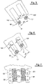
- Engagement wheel 400 is provided with teeth 401 for engaging the spacing SP existing between linear portions LI, as shown in figures 2 , 3 and 8 . Rotation of engagement wheel 400 will feed the leading portion 91 of the flat coil through passage 301.
- drum 200 When engagement wheel 400 is being rotated, also drum 200 will be rotated to feed the leading portion 91 and unwind the rest of the coil portion 90' from drum 200 without modifying the pitch distance PT existing between the linear portions LI.
- stator core 101 is indexed by a rotation motion around longitudinal axis 101', which is the central longitudinal axis of the stator core 101, as shown in figures 2 and 3 .
- rotation of drum 200, together with rotation of engagement wheel 400 and rotation of stator core 101 align each linear portion LI of the flat coil with a specific slot 102, where the linear portion LI needs to be inserted though the entrance 102', and thereafter positioned in the depth of a specific slot 102.
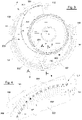
- Figure 4 illustrates how the configuration of the guide passage 301 and the described movements of the drum 200, the engagement wheel 400 and the stator core 101 progressively insert the linear portions LI in the respective slots 102, and position the linear portions at the required depth within the slots 102.
- angle A gradually reduces as the linear portions LI move within the slots by movement along passage 301 until the angle becomes zero when a linear portion leaves passage 301, and results positioned at a required final position within a slot 102 (see linear portions LI1 in figure 4 ).
- the situation of figure 4 is the initial stage of the insertion of the flat coil, in which the linear portions become positioned at the bottom of the slots 102.
- the guide plates 302, 303, 304 are duplicated on the opposite side of the stator core, so that the linear portions LI are guided by two aligned passages 301 to be parallel to the entrance of the slots, where the linear portion need to be inserted.
- Structure 305 located in the stator core can be adopted for connecting the guide plates, as shown in figures 2 and 9 .
- passages 301 can guide portions GL1 of linear portions LI.
- Guide portions GL1 can be at the ends of linear portions LI, and adjacent to turn portions T, as shown in figure 9 .
- a drive unit (not shown) is attached to shaft 402 of engagement wheel 400 for the rotation of guide wheel 400, as shown in figure 8 .
- linear portions LI having different pitch distance PT2 need to be in inserted in the part of the slot that is nearer to the entrance.
- the second flat coil can be wound around another drum like 200 having teeth at a pitch distance PT2.
- a second engagement wheel 400 will need to have a pitch distance PT2 between the teeth.
- guide plates 302, 303 and 304 will need to form a passage having a configuration that progressively rotates, or orients the linear portions with specific angles for entering the slots and for maintaining pitch distance PT2 constant.
- stator core 101 can be transferred and positioned for the successive insertion of the second flat coil having pitch distance PT2. This will avoid having to replace drum 200, engagement wheel 400, and guide plates 302, 303 and 304 in a single unit.
- passage 301 can be accomplished by means of a single guide surface along which the linear portions LI are caused to engage and move in order be rotated and inserted in the slots 102 of stator core 101, like occurs on guide surface of plate 303 when guide 304 is removed.
Landscapes
- Engineering & Computer Science (AREA)
- Power Engineering (AREA)
- Manufacturing & Machinery (AREA)
- Manufacture Of Motors, Generators (AREA)
Priority Applications (2)
| Application Number | Priority Date | Filing Date | Title |
|---|---|---|---|
| RS20220863A RS63578B1 (sr) | 2015-07-20 | 2016-07-08 | Postupak i aparatura za umetanje sklopova talasastih kalemova u proreze jezgara dinamoelektričnih mašina |
| SI201631599T SI3326274T1 (sl) | 2015-07-20 | 2016-07-08 | Postopek in naprava za vstavljanje sklopov valovitih tuljav v reže jeder dinamoelektričnih strojev |
Applications Claiming Priority (2)
| Application Number | Priority Date | Filing Date | Title |
|---|---|---|---|
| ITUB2015A002330A ITUB20152330A1 (it) | 2015-07-20 | 2015-07-20 | Metodo e apparecchiatura per inserire assemblati di bobine ondulate nelle cave di nuclei di macchine dinamoelettriche |
| PCT/IB2016/054104 WO2017013523A1 (en) | 2015-07-20 | 2016-07-08 | Method and apparatus for inserting undulated coil assemblies in the slots of cores of dynamoelectric machines |
Publications (2)
| Publication Number | Publication Date |
|---|---|
| EP3326274A1 EP3326274A1 (en) | 2018-05-30 |
| EP3326274B1 true EP3326274B1 (en) | 2022-08-31 |
Family
ID=54364499
Family Applications (1)
| Application Number | Title | Priority Date | Filing Date |
|---|---|---|---|
| EP16753473.4A Active EP3326274B1 (en) | 2015-07-20 | 2016-07-08 | Method and apparatus for inserting undulated coil assemblies in the slots of cores of dynamoelectric machines |
Country Status (10)
| Country | Link |
|---|---|
| US (2) | US11557946B2 (pl) |
| EP (1) | EP3326274B1 (pl) |
| KR (1) | KR102662927B1 (pl) |
| CN (1) | CN107836075B (pl) |
| ES (1) | ES2930586T3 (pl) |
| IT (1) | ITUB20152330A1 (pl) |
| PL (1) | PL3326274T3 (pl) |
| RS (1) | RS63578B1 (pl) |
| SI (1) | SI3326274T1 (pl) |
| WO (1) | WO2017013523A1 (pl) |
Families Citing this family (14)
| Publication number | Priority date | Publication date | Assignee | Title |
|---|---|---|---|---|
| ITTO20110199A1 (it) | 2011-03-07 | 2012-09-08 | Atop Spa | Apparecchio e procedimento per l'allineamento di conduttori di elementi di bobine in nuclei di macchine dinamo elettriche per compiere operazioni di saldatura. |
| ITTO20110435A1 (it) | 2011-05-16 | 2012-11-17 | Atop Spa | Apparecchio e procedimento per la realizzazione di elementi di bobine per nuclei di macchine dinamo elettriche mediante piegatura. |
| ITPI20130092A1 (it) | 2013-10-18 | 2015-04-19 | Atop Spa | Apparecchiatura e metodo per produrre componenti di macchine dinamoelettriche |
| PL3289672T3 (pl) | 2015-04-30 | 2019-10-31 | Atop Spa | Sposoby i urządzenia do tworzenia przeplatanych zespołów falistych cewek |
| ITUB20152330A1 (it) | 2015-07-20 | 2017-01-20 | Atop Spa | Metodo e apparecchiatura per inserire assemblati di bobine ondulate nelle cave di nuclei di macchine dinamoelettriche |
| KR102010299B1 (ko) | 2017-08-11 | 2019-08-13 | 엘지전자 주식회사 | 회전전기기계의 헤어핀 정렬장치 |
| JP6591574B2 (ja) * | 2018-01-15 | 2019-10-16 | 本田技研工業株式会社 | 波巻コイルの保持装置、保持方法及び挿入方法 |
| PL3544161T3 (pl) * | 2018-03-20 | 2020-11-02 | Aumann Espelkamp Gmbh | Sposób i urządzenie do wprowadzania maty uzwojeń falistych do wirnika albo stojana maszyny elektrycznej, w szczególności pakietu blach stojana |
| EP3731379B1 (en) * | 2019-04-23 | 2021-11-10 | Marsilli S.p.A. | Stator for electric motors and method for providing such stator |
| DE102020103165A1 (de) | 2019-05-16 | 2020-11-19 | Schaeffler Technologies AG & Co. KG | Stator für eine elektrische Maschine mit bandförmiger Wicklungseinheit für eine Statorwicklung und Verfahren zu dessen Herstellung |
| DE102019117308A1 (de) * | 2019-06-27 | 2020-12-31 | Schaeffler Technologies AG & Co. KG | Verfahren zur Herstellung eines Stators für eine elektrische Maschine |
| DE102019120262A1 (de) * | 2019-07-26 | 2021-01-28 | Grob-Werke Gmbh & Co. Kg | Kranzanordnungsvorrichtung und Kranzanordnungsverfahren |
| DE102020104915B4 (de) | 2020-02-25 | 2023-08-10 | Gehring Technologies Gmbh + Co. Kg | Vorrichtung und Verfahren zur Überführung von Leiterstücken in eine Soll-Anordnung |
| KR102745102B1 (ko) * | 2024-06-24 | 2024-12-23 | (주) 신창에프에이 | 컨티뉴어스 와인딩을 위한 롤업 장치 |
Family Cites Families (87)
| Publication number | Priority date | Publication date | Assignee | Title |
|---|---|---|---|---|
| US2476744A (en) | 1946-09-11 | 1949-07-19 | Leece Neville Co | Coil shaping apparatus |
| GB644761A (en) | 1947-10-10 | 1950-10-18 | Gen Motors Corp | Improved apparatus for the manufacture of armatures for dynamo-electric machines |
| US3631591A (en) | 1967-05-22 | 1972-01-04 | Essex International Inc | Method and apparatus for making concentric, multiturn nested dynamoelectric machine field coils |
| US3543337A (en) | 1968-08-14 | 1970-12-01 | Microdot Inc | Apparatus for manufacturing insulators for multiple conductor connectors |
| US3689976A (en) | 1971-04-15 | 1972-09-12 | Smith Corp A O | Coil transfer apparatus |
| GB1496445A (en) | 1975-03-26 | 1977-12-30 | Nii Ex I Avtomobil Elektroobor | Bar windings for electrical machines |
| US4052783A (en) | 1976-05-17 | 1977-10-11 | Shively Lawrence A | Apparatus and method for winding armatures |
| US4727742A (en) | 1986-02-24 | 1988-03-01 | Amp Incorporated | Crimping tool for fiber optic splice connector |
| US4750258A (en) | 1986-10-14 | 1988-06-14 | Emerson Electric Co. | Apparatus for and method of simultaneously, axially inserting multiple pole, multiple phase windings |
| IT1219076B (it) | 1988-03-04 | 1990-04-24 | Pavesi & C Spa Off Mec | Procedimento e dispositivo per inserire una pluralita di isolatori di fase nelle cave dello statore di una macchina dinamoelettrica |
| US5714824A (en) * | 1994-06-23 | 1998-02-03 | Hydro-Quebec | Conductor section for a stator frame of a polyphase dynamoelectric machine |
| US5586384A (en) | 1995-04-28 | 1996-12-24 | Globe Products Inc. | Stator manufacturing method and apparatus |
| US6389678B1 (en) | 1996-05-31 | 2002-05-21 | Emerson Electric Co. | Method of constructing a salient pole motor |
| JP3708288B2 (ja) | 1997-05-23 | 2005-10-19 | 松下電器産業株式会社 | 電機子コイルの巻線機とその巻線機による巻線方法 |
| JP3952346B2 (ja) | 1998-05-20 | 2007-08-01 | 株式会社デンソー | 回転電機及びその製造方法 |
| DE69923623T2 (de) | 1998-05-25 | 2005-07-07 | Denso Corp., Kariya | Kraftfahrzeugwechselstromgenerator und Herstellungsverfahren |
| JP3196738B2 (ja) | 1998-09-11 | 2001-08-06 | 株式会社デンソー | ステータ製造装置及びステータ製造方法 |
| DE19847843A1 (de) | 1998-10-16 | 2000-05-04 | Siemens Ag | Halterung |
| DE19902198C2 (de) | 1999-01-21 | 2001-02-22 | Elmotec Elektro Motoren Tech | Verfahren und Vorrichtung zum axialen Einziehen von Spulen in Statoren oder Rotoren elektrischer Maschinen |
| JP3201397B2 (ja) | 1999-03-30 | 2001-08-20 | 株式会社デンソー | 回転電機の製造方法 |
| JP3104700B1 (ja) | 1999-03-30 | 2000-10-30 | 株式会社デンソー | 回転電機の巻線接合方法および装置 |
| JP3199068B2 (ja) | 1999-03-31 | 2001-08-13 | 株式会社デンソー | ステータの製造装置 |
| FR2791827B1 (fr) * | 1999-04-02 | 2005-10-28 | Denso Corp | Procede de fabrication de stator de machine tournante |
| JP3843644B2 (ja) | 1999-04-14 | 2006-11-08 | 株式会社デンソー | 回転電機のステータおよびその製造方法 |
| IT1309852B1 (it) | 1999-06-15 | 2002-02-05 | Atop Spa | Macchina e metodo per l'inserimento di isolante nelle cave di indottidi motori elettrici. |
| JP4537519B2 (ja) | 1999-12-22 | 2010-09-01 | 澤藤電機株式会社 | ステータコアの巻線装置 |
| JP3589134B2 (ja) | 2000-01-12 | 2004-11-17 | 株式会社デンソー | ステータ製造方法及びその装置 |
| JP3707606B2 (ja) | 2000-02-07 | 2005-10-19 | 三菱電機株式会社 | 回転電機の巻線組立およびその製造方法ならびにその巻線組立を用いた回転電機の固定子 |
| US7730401B2 (en) | 2001-05-16 | 2010-06-01 | Synaptics Incorporated | Touch screen with user interface enhancement |
| US20030135988A1 (en) | 2001-10-12 | 2003-07-24 | Massimo Pelletta | Dynamo-electric machine component core coil forming system |
| JP3551375B2 (ja) | 2001-12-26 | 2004-08-04 | 株式会社デンソー | 回転電機およびその製造方法 |
| JP3740421B2 (ja) | 2002-01-10 | 2006-02-01 | 株式会社日立製作所 | 回転電機と固定子導線の接続方法 |
| JP3889630B2 (ja) | 2002-01-21 | 2007-03-07 | 三菱電機株式会社 | 回転電機の巻線接合方法 |
| JP3680801B2 (ja) | 2002-02-27 | 2005-08-10 | 株式会社デンソー | 回転電機の巻線接合方法 |
| US20040046476A1 (en) | 2002-05-14 | 2004-03-11 | Raffaele Becherucci | Dynamo-electric machine component winding methods and apparatus |
| JP3775349B2 (ja) * | 2002-06-03 | 2006-05-17 | 株式会社デンソー | 回転電機の固定子巻線の製造方法、巻線構造および巻線の製造方法 |
| JP3783659B2 (ja) | 2002-06-25 | 2006-06-07 | 株式会社デンソー | 回転電機のセグメント順次接合ステータコイルの製造方法 |
| JP2004032897A (ja) | 2002-06-25 | 2004-01-29 | Denso Corp | 回転電機のセグメント順次接合ステータコイルおよびその製造方法 |
| JP3832392B2 (ja) * | 2002-06-25 | 2006-10-11 | 株式会社デンソー | 回転電機のセグメント順次接合ステータコイルおよびその製造方法 |
| US7275299B2 (en) | 2002-07-30 | 2007-10-02 | Aisin Aw Co., Ltd. | Motor manufacturing process |
| JP2004072839A (ja) * | 2002-08-02 | 2004-03-04 | Toyota Motor Corp | コイルセグメントの環状整列治具および環状整列方法 |
| JP3894483B2 (ja) | 2002-09-04 | 2007-03-22 | 三菱電機株式会社 | 回転電機の巻線部材および巻線組立の製造方法並びにその巻線部材の製造装置 |
| FR2845536B1 (fr) | 2002-10-07 | 2005-01-07 | Valeo Equip Electr Moteur | Agencement de soudage des extremites libres de paires de segments de conducteurs electriques d'un bobinage d'une machine electrique tournante |
| DE10315361A1 (de) | 2003-04-03 | 2004-10-14 | Robert Bosch Gmbh | Verfahren zur Herstellung von Wicklungen und Wicklungsverschaltungen |
| US7370401B2 (en) | 2003-04-03 | 2008-05-13 | Atop S.P.A. | Apparatus and methods for wire coil lead placement |
| JP4435739B2 (ja) | 2004-01-28 | 2010-03-24 | 三菱電機株式会社 | 回転電機の巻線組立の製造方法およびその巻線組立の製造装置 |
| US7654123B2 (en) | 2004-02-05 | 2010-02-02 | In Motion Technologies Pty. Ltd. | Automated manufacturing machine |
| US7325764B2 (en) | 2004-04-26 | 2008-02-05 | Globe Motors, Inc. | Method and apparatus for winding field coils for dynamo-electric machines |
| DE102004035084A1 (de) | 2004-07-20 | 2006-02-16 | Elmotec Statomat Vertriebs Gmbh | Verfahren und Vorrichtung zur Herstellung einer Spulenwicklung für Statoren oder Rotoren elektrischer Maschinen sowie damit herzustellender Stator oder Rotor |
| US7269888B2 (en) * | 2004-08-10 | 2007-09-18 | Visteon Global Technologies, Inc. | Method of making cascaded multilayer stator winding with interleaved transitions |
| JP4654068B2 (ja) | 2005-05-24 | 2011-03-16 | 日立オートモティブシステムズ株式会社 | 接合電線と接合電線の加工方法,回転電機の固定子と回転電機の固定子の製造方法及び接合電線製造装置 |
| US7549941B2 (en) | 2005-09-09 | 2009-06-23 | Eaton Corporation | Vehicle differential including pump with variable-engagement clutch |
| FR2896350B1 (fr) * | 2006-01-16 | 2008-02-29 | Valeo Equip Electr Moteur | Procede pour realiser le bobinage d'un stator de machine electrique tournante, et stator obtenu par ce procede |
| FR2896351B1 (fr) * | 2006-01-16 | 2008-04-18 | Valeo Equip Electr Moteur | Procede pour realiser un stator de machine electrique tournante et agencement de conducteurs sur un support |
| ITPI20060031A1 (it) | 2006-03-13 | 2007-09-14 | Atop Spa | Apparecchiatura e metodi per avvolgere bobine di filo attorno a nuclei di macchine elettriche. |
| JP4715776B2 (ja) * | 2007-03-06 | 2011-07-06 | トヨタ自動車株式会社 | モータ固定子の製造方法及びモータ固定子 |
| US7480987B1 (en) | 2007-03-22 | 2009-01-27 | Tecnomatic, S.P.A. | Method for pre-forming conductors for motor rotors and stators |
| US7941910B2 (en) | 2007-03-22 | 2011-05-17 | Tecnomatic S.P.A. | Method for removing winding conductors from a twisting machine and placing them in a rotor stator stack |
| US8215000B2 (en) | 2007-07-20 | 2012-07-10 | Tecnomatic, S.P.A. | Methods for twisting rotor and stator ends |
| JP4461399B2 (ja) | 2008-03-05 | 2010-05-12 | 株式会社デンソー | 回転電機用コイル組立体の編込み機 |
| JP4962512B2 (ja) * | 2008-03-12 | 2012-06-27 | 株式会社デンソー | 固定子コイルの製造方法 |
| ITPI20080023A1 (it) | 2008-03-19 | 2009-09-20 | Atop Spa | Apparecchiature e metodi per avvolgere supporti per bobine e poli singoli di nuclei per macchine dinamo elettriche |
| CN102017372B (zh) | 2008-04-07 | 2015-05-20 | 雷米技术有限公司 | 用于弯曲电机导体的方法和设备 |
| DE102008019479A1 (de) | 2008-04-17 | 2009-10-29 | Elmotec Statomat Vertriebs Gmbh | Stator oder Rotor für elektrische Maschinen und Verfahren zu seiner Herstellung |
| JP5233682B2 (ja) | 2009-01-08 | 2013-07-10 | アイシン・エィ・ダブリュ株式会社 | 曲げ加工機 |
| IT1394587B1 (it) | 2009-04-29 | 2012-07-05 | Atop Spa | Apparecchiatura e metodo per avvolgere e terminare nuclei per macchine dinamo elettriche |
| TWI392196B (zh) | 2009-06-30 | 2013-04-01 | Victory Ind Corp | Method of Making Stirrups for Automobile Generators |
| FR2947968A1 (fr) | 2009-07-09 | 2011-01-14 | Valeo Equip Electr Moteur | Bobinage d'une machine electrique tournante |
| MX2012009592A (es) | 2010-03-03 | 2012-09-12 | Tecnomatic Spa | Metodo y aparato para elaborar un estator para una maquina electrica y estator de maquina electrica con alto factor de llenado. |
| CN102812620B (zh) * | 2010-03-11 | 2015-09-30 | 株式会社丰田自动织机 | 旋转电机的定子、定子的制造方法、以及定子的线圈的制造方法 |
| US9467029B2 (en) | 2010-06-21 | 2016-10-11 | Atop S.P.A. | Apparatus and method for winding supports for coils and single poles of cores for dynamoelectric machines |
| BR122020013329B1 (pt) * | 2010-07-08 | 2020-10-27 | Tecnomatic S.P.A | estator ou rotor, máquina elétrica e veículo elétrico |
| FR2968858B1 (fr) | 2010-12-10 | 2013-07-26 | Valeo Equip Electr Moteur | Bobinage d'une machine electrique tournante |
| MX2013005968A (es) | 2011-01-04 | 2013-07-29 | Tecnomatic Spa | Metodo y artefacto de torcido de porciones de extremo de conductores de barra, en particular para devanados de barra de maquinas electricas. |
| ITTO20110199A1 (it) * | 2011-03-07 | 2012-09-08 | Atop Spa | Apparecchio e procedimento per l'allineamento di conduttori di elementi di bobine in nuclei di macchine dinamo elettriche per compiere operazioni di saldatura. |
| ITTO20110435A1 (it) | 2011-05-16 | 2012-11-17 | Atop Spa | Apparecchio e procedimento per la realizzazione di elementi di bobine per nuclei di macchine dinamo elettriche mediante piegatura. |
| BR112014000323B1 (pt) | 2011-07-07 | 2020-02-27 | Tecnomatic S.P.A. | Estator para uma máquina elétrica, máquina elétrica e veículo de acionamento elétrico ou híbrido |
| DE112012004477T5 (de) | 2011-10-27 | 2014-07-10 | Toyota Jidosha Kabushiki Kaisha | Segmentspule, Verfahren zur Herstellung einer Segmentspule, Drahtstab für eine Segmentspule und Stator |
| JP2013102569A (ja) * | 2011-11-07 | 2013-05-23 | Toyota Motor Corp | ステータの製造方法及び製造装置 |
| JP2013135527A (ja) | 2011-12-26 | 2013-07-08 | Asmo Co Ltd | ステータの製造方法、ステータの製造装置及びステータ |
| WO2013190860A1 (ja) | 2012-06-22 | 2013-12-27 | 本田技研工業株式会社 | ステータ製造装置及びステータ製造方法 |
| US9071116B2 (en) * | 2013-01-17 | 2015-06-30 | Remy Technologies, Llc | Apparatus for installing stator winding conductors |
| ITPI20130020A1 (it) | 2013-03-20 | 2014-09-21 | Atop Spa | Apparecchiatura e metodo per produrre statori di macchine dinamoelettriche formati da un assemblato di segmenti di polo |
| ITPI20130092A1 (it) | 2013-10-18 | 2015-04-19 | Atop Spa | Apparecchiatura e metodo per produrre componenti di macchine dinamoelettriche |
| EP3114757B1 (en) | 2014-03-07 | 2018-08-29 | ATOP S.p.A. | Apparatus and method for forming coil members |
| PL3289672T3 (pl) | 2015-04-30 | 2019-10-31 | Atop Spa | Sposoby i urządzenia do tworzenia przeplatanych zespołów falistych cewek |
| ITUB20152330A1 (it) | 2015-07-20 | 2017-01-20 | Atop Spa | Metodo e apparecchiatura per inserire assemblati di bobine ondulate nelle cave di nuclei di macchine dinamoelettriche |
-
2015
- 2015-07-20 IT ITUB2015A002330A patent/ITUB20152330A1/it unknown
-
2016
- 2016-07-08 RS RS20220863A patent/RS63578B1/sr unknown
- 2016-07-08 EP EP16753473.4A patent/EP3326274B1/en active Active
- 2016-07-08 KR KR1020187001879A patent/KR102662927B1/ko active Active
- 2016-07-08 CN CN201680040846.5A patent/CN107836075B/zh active Active
- 2016-07-08 US US15/746,365 patent/US11557946B2/en active Active
- 2016-07-08 PL PL16753473.4T patent/PL3326274T3/pl unknown
- 2016-07-08 ES ES16753473T patent/ES2930586T3/es active Active
- 2016-07-08 SI SI201631599T patent/SI3326274T1/sl unknown
- 2016-07-08 WO PCT/IB2016/054104 patent/WO2017013523A1/en not_active Ceased
-
2022
- 2022-12-08 US US18/078,040 patent/US12470114B2/en active Active
Also Published As
| Publication number | Publication date |
|---|---|
| CN107836075B (zh) | 2020-05-08 |
| RS63578B1 (sr) | 2022-10-31 |
| CN107836075A (zh) | 2018-03-23 |
| US20180233999A1 (en) | 2018-08-16 |
| EP3326274A1 (en) | 2018-05-30 |
| PL3326274T3 (pl) | 2022-10-10 |
| US20230109380A1 (en) | 2023-04-06 |
| WO2017013523A1 (en) | 2017-01-26 |
| ITUB20152330A1 (it) | 2017-01-20 |
| KR20180030840A (ko) | 2018-03-26 |
| ES2930586T3 (es) | 2022-12-19 |
| SI3326274T1 (sl) | 2022-11-30 |
| KR102662927B1 (ko) | 2024-05-02 |
| US12470114B2 (en) | 2025-11-11 |
| US11557946B2 (en) | 2023-01-17 |
Similar Documents
| Publication | Publication Date | Title |
|---|---|---|
| US12470114B2 (en) | Apparatus for inserting an undulated coil assembly in slots of a core of a stator of a dynamoelectric machine | |
| US10284060B2 (en) | Stator assembly method and stator assembly apparatus | |
| US9071116B2 (en) | Apparatus for installing stator winding conductors | |
| US9735641B2 (en) | Rotary electric machine and manufacturing method therefor | |
| CN103107659B (zh) | 扁线的绕线结构 | |
| US9680358B2 (en) | Method for manufacturing a winding body that is used in an armature winding for an electric machine | |
| US8371020B2 (en) | Method of manufacturing stator coil | |
| CN105896780B (zh) | 三相交流电动机 | |
| JP5332347B2 (ja) | 回転電機のコイル組立体用のコイル線材 | |
| US10666105B2 (en) | Wire assembly for rotary electric machine and corresponding method to obtain the wire assembly | |
| EP2680412B1 (en) | Arrangement of coil wires in a rotor of an electric motor | |
| US8754566B2 (en) | Assembling method for a stator and stator produced thereby | |
| EP2106012A2 (en) | Electric rotational motor | |
| US12374972B2 (en) | Method for producing a coil winding for insertion into radially open slots of stators or rotors of electrical machines | |
| JP7357427B2 (ja) | 巻線装置及びコイル製造方法 | |
| US20180226852A1 (en) | Rotating electric machine | |
| US8127430B2 (en) | Method of assembling split core type stator of inner rotor type rotary electric machine | |
| CN109937517A (zh) | 具有可推上式绕组的用于电机的转子 | |
| JP6196804B2 (ja) | 回転電機のステータ | |
| KR101803879B1 (ko) | 회전전기기계의 스테이터 및 그의 제조방법 | |
| JP4443286B2 (ja) | 回転電動機の固定子、回転電動機のコイル装着方法、コイル巻線機 | |
| JP2013118764A (ja) | ステータ製造方法及びステータ製造装置 | |
| JPH11312620A (ja) | 巻線装置 | |
| KR20160017970A (ko) | 회전 전기 기계용 스테이터 권선의 와이어를 형성하기 위한 형성 툴 |
Legal Events
| Date | Code | Title | Description |
|---|---|---|---|
| STAA | Information on the status of an ep patent application or granted ep patent |
Free format text: STATUS: THE INTERNATIONAL PUBLICATION HAS BEEN MADE |
|
| PUAI | Public reference made under article 153(3) epc to a published international application that has entered the european phase |
Free format text: ORIGINAL CODE: 0009012 |
|
| STAA | Information on the status of an ep patent application or granted ep patent |
Free format text: STATUS: REQUEST FOR EXAMINATION WAS MADE |
|
| 17P | Request for examination filed |
Effective date: 20180202 |
|
| AK | Designated contracting states |
Kind code of ref document: A1 Designated state(s): AL AT BE BG CH CY CZ DE DK EE ES FI FR GB GR HR HU IE IS IT LI LT LU LV MC MK MT NL NO PL PT RO RS SE SI SK SM TR |
|
| AX | Request for extension of the european patent |
Extension state: BA ME |
|
| DAV | Request for validation of the european patent (deleted) | ||
| DAX | Request for extension of the european patent (deleted) | ||
| STAA | Information on the status of an ep patent application or granted ep patent |
Free format text: STATUS: EXAMINATION IS IN PROGRESS |
|
| 17Q | First examination report despatched |
Effective date: 20190207 |
|
| GRAP | Despatch of communication of intention to grant a patent |
Free format text: ORIGINAL CODE: EPIDOSNIGR1 |
|
| STAA | Information on the status of an ep patent application or granted ep patent |
Free format text: STATUS: GRANT OF PATENT IS INTENDED |
|
| INTG | Intention to grant announced |
Effective date: 20220421 |
|
| GRAS | Grant fee paid |
Free format text: ORIGINAL CODE: EPIDOSNIGR3 |
|
| GRAA | (expected) grant |
Free format text: ORIGINAL CODE: 0009210 |
|
| STAA | Information on the status of an ep patent application or granted ep patent |
Free format text: STATUS: THE PATENT HAS BEEN GRANTED |
|
| RAP3 | Party data changed (applicant data changed or rights of an application transferred) |
Owner name: ATOP S.P.A. |
|
| AK | Designated contracting states |
Kind code of ref document: B1 Designated state(s): AL AT BE BG CH CY CZ DE DK EE ES FI FR GB GR HR HU IE IS IT LI LT LU LV MC MK MT NL NO PL PT RO RS SE SI SK SM TR |
|
| REG | Reference to a national code |
Ref country code: CH Ref legal event code: EP Ref country code: GB Ref legal event code: FG4D |
|
| REG | Reference to a national code |
Ref country code: AT Ref legal event code: REF Ref document number: 1516033 Country of ref document: AT Kind code of ref document: T Effective date: 20220915 Ref country code: DE Ref legal event code: R096 Ref document number: 602016074663 Country of ref document: DE |
|
| REG | Reference to a national code |
Ref country code: RO Ref legal event code: EPE |
|
| REG | Reference to a national code |
Ref country code: IE Ref legal event code: FG4D |
|
| REG | Reference to a national code |
Ref country code: SK Ref legal event code: T3 Ref document number: E 40415 Country of ref document: SK |
|
| REG | Reference to a national code |
Ref country code: ES Ref legal event code: FG2A Ref document number: 2930586 Country of ref document: ES Kind code of ref document: T3 Effective date: 20221219 |
|
| REG | Reference to a national code |
Ref country code: LT Ref legal event code: MG9D |
|
| REG | Reference to a national code |
Ref country code: NL Ref legal event code: MP Effective date: 20220831 |
|
| PG25 | Lapsed in a contracting state [announced via postgrant information from national office to epo] |
Ref country code: SE Free format text: LAPSE BECAUSE OF FAILURE TO SUBMIT A TRANSLATION OF THE DESCRIPTION OR TO PAY THE FEE WITHIN THE PRESCRIBED TIME-LIMIT Effective date: 20220831 Ref country code: NO Free format text: LAPSE BECAUSE OF FAILURE TO SUBMIT A TRANSLATION OF THE DESCRIPTION OR TO PAY THE FEE WITHIN THE PRESCRIBED TIME-LIMIT Effective date: 20221130 Ref country code: LV Free format text: LAPSE BECAUSE OF FAILURE TO SUBMIT A TRANSLATION OF THE DESCRIPTION OR TO PAY THE FEE WITHIN THE PRESCRIBED TIME-LIMIT Effective date: 20220831 Ref country code: LT Free format text: LAPSE BECAUSE OF FAILURE TO SUBMIT A TRANSLATION OF THE DESCRIPTION OR TO PAY THE FEE WITHIN THE PRESCRIBED TIME-LIMIT Effective date: 20220831 Ref country code: FI Free format text: LAPSE BECAUSE OF FAILURE TO SUBMIT A TRANSLATION OF THE DESCRIPTION OR TO PAY THE FEE WITHIN THE PRESCRIBED TIME-LIMIT Effective date: 20220831 |
|
| PG25 | Lapsed in a contracting state [announced via postgrant information from national office to epo] |
Ref country code: IS Free format text: LAPSE BECAUSE OF FAILURE TO SUBMIT A TRANSLATION OF THE DESCRIPTION OR TO PAY THE FEE WITHIN THE PRESCRIBED TIME-LIMIT Effective date: 20221231 Ref country code: HR Free format text: LAPSE BECAUSE OF FAILURE TO SUBMIT A TRANSLATION OF THE DESCRIPTION OR TO PAY THE FEE WITHIN THE PRESCRIBED TIME-LIMIT Effective date: 20220831 Ref country code: GR Free format text: LAPSE BECAUSE OF FAILURE TO SUBMIT A TRANSLATION OF THE DESCRIPTION OR TO PAY THE FEE WITHIN THE PRESCRIBED TIME-LIMIT Effective date: 20221201 |
|
| PG25 | Lapsed in a contracting state [announced via postgrant information from national office to epo] |
Ref country code: SM Free format text: LAPSE BECAUSE OF FAILURE TO SUBMIT A TRANSLATION OF THE DESCRIPTION OR TO PAY THE FEE WITHIN THE PRESCRIBED TIME-LIMIT Effective date: 20220831 Ref country code: PT Free format text: LAPSE BECAUSE OF FAILURE TO SUBMIT A TRANSLATION OF THE DESCRIPTION OR TO PAY THE FEE WITHIN THE PRESCRIBED TIME-LIMIT Effective date: 20230102 Ref country code: DK Free format text: LAPSE BECAUSE OF FAILURE TO SUBMIT A TRANSLATION OF THE DESCRIPTION OR TO PAY THE FEE WITHIN THE PRESCRIBED TIME-LIMIT Effective date: 20220831 |
|
| PG25 | Lapsed in a contracting state [announced via postgrant information from national office to epo] |
Ref country code: EE Free format text: LAPSE BECAUSE OF FAILURE TO SUBMIT A TRANSLATION OF THE DESCRIPTION OR TO PAY THE FEE WITHIN THE PRESCRIBED TIME-LIMIT Effective date: 20220831 |
|
| REG | Reference to a national code |
Ref country code: DE Ref legal event code: R097 Ref document number: 602016074663 Country of ref document: DE |
|
| P01 | Opt-out of the competence of the unified patent court (upc) registered |
Effective date: 20230508 |
|
| PG25 | Lapsed in a contracting state [announced via postgrant information from national office to epo] |
Ref country code: NL Free format text: LAPSE BECAUSE OF FAILURE TO SUBMIT A TRANSLATION OF THE DESCRIPTION OR TO PAY THE FEE WITHIN THE PRESCRIBED TIME-LIMIT Effective date: 20220831 Ref country code: AL Free format text: LAPSE BECAUSE OF FAILURE TO SUBMIT A TRANSLATION OF THE DESCRIPTION OR TO PAY THE FEE WITHIN THE PRESCRIBED TIME-LIMIT Effective date: 20220831 |
|
| PLBE | No opposition filed within time limit |
Free format text: ORIGINAL CODE: 0009261 |
|
| STAA | Information on the status of an ep patent application or granted ep patent |
Free format text: STATUS: NO OPPOSITION FILED WITHIN TIME LIMIT |
|
| 26N | No opposition filed |
Effective date: 20230601 |
|
| PG25 | Lapsed in a contracting state [announced via postgrant information from national office to epo] |
Ref country code: MC Free format text: LAPSE BECAUSE OF FAILURE TO SUBMIT A TRANSLATION OF THE DESCRIPTION OR TO PAY THE FEE WITHIN THE PRESCRIBED TIME-LIMIT Effective date: 20220831 |
|
| PG25 | Lapsed in a contracting state [announced via postgrant information from national office to epo] |
Ref country code: MC Free format text: LAPSE BECAUSE OF FAILURE TO SUBMIT A TRANSLATION OF THE DESCRIPTION OR TO PAY THE FEE WITHIN THE PRESCRIBED TIME-LIMIT Effective date: 20220831 |
|
| REG | Reference to a national code |
Ref country code: BE Ref legal event code: MM Effective date: 20230731 |
|
| PG25 | Lapsed in a contracting state [announced via postgrant information from national office to epo] |
Ref country code: LU Free format text: LAPSE BECAUSE OF NON-PAYMENT OF DUE FEES Effective date: 20230708 |
|
| PG25 | Lapsed in a contracting state [announced via postgrant information from national office to epo] |
Ref country code: LU Free format text: LAPSE BECAUSE OF NON-PAYMENT OF DUE FEES Effective date: 20230708 |
|
| REG | Reference to a national code |
Ref country code: IE Ref legal event code: MM4A |
|
| PG25 | Lapsed in a contracting state [announced via postgrant information from national office to epo] |
Ref country code: BE Free format text: LAPSE BECAUSE OF NON-PAYMENT OF DUE FEES Effective date: 20230731 |
|
| PG25 | Lapsed in a contracting state [announced via postgrant information from national office to epo] |
Ref country code: IE Free format text: LAPSE BECAUSE OF NON-PAYMENT OF DUE FEES Effective date: 20230708 |
|
| PG25 | Lapsed in a contracting state [announced via postgrant information from national office to epo] |
Ref country code: IE Free format text: LAPSE BECAUSE OF NON-PAYMENT OF DUE FEES Effective date: 20230708 |
|
| PG25 | Lapsed in a contracting state [announced via postgrant information from national office to epo] |
Ref country code: BG Free format text: LAPSE BECAUSE OF FAILURE TO SUBMIT A TRANSLATION OF THE DESCRIPTION OR TO PAY THE FEE WITHIN THE PRESCRIBED TIME-LIMIT Effective date: 20220831 |
|
| PG25 | Lapsed in a contracting state [announced via postgrant information from national office to epo] |
Ref country code: BG Free format text: LAPSE BECAUSE OF FAILURE TO SUBMIT A TRANSLATION OF THE DESCRIPTION OR TO PAY THE FEE WITHIN THE PRESCRIBED TIME-LIMIT Effective date: 20220831 |
|
| PGFP | Annual fee paid to national office [announced via postgrant information from national office to epo] |
Ref country code: PL Payment date: 20250610 Year of fee payment: 10 |
|
| PGFP | Annual fee paid to national office [announced via postgrant information from national office to epo] |
Ref country code: RS Payment date: 20250630 Year of fee payment: 10 |
|
| PGFP | Annual fee paid to national office [announced via postgrant information from national office to epo] |
Ref country code: RO Payment date: 20250625 Year of fee payment: 10 |
|
| PG25 | Lapsed in a contracting state [announced via postgrant information from national office to epo] |
Ref country code: CY Free format text: LAPSE BECAUSE OF FAILURE TO SUBMIT A TRANSLATION OF THE DESCRIPTION OR TO PAY THE FEE WITHIN THE PRESCRIBED TIME-LIMIT; INVALID AB INITIO Effective date: 20160708 |
|
| PGFP | Annual fee paid to national office [announced via postgrant information from national office to epo] |
Ref country code: SK Payment date: 20250606 Year of fee payment: 10 |
|
| PGFP | Annual fee paid to national office [announced via postgrant information from national office to epo] |
Ref country code: CZ Payment date: 20250609 Year of fee payment: 10 |
|
| PGFP | Annual fee paid to national office [announced via postgrant information from national office to epo] |
Ref country code: SI Payment date: 20250606 Year of fee payment: 10 |
|
| PG25 | Lapsed in a contracting state [announced via postgrant information from national office to epo] |
Ref country code: HU Free format text: LAPSE BECAUSE OF FAILURE TO SUBMIT A TRANSLATION OF THE DESCRIPTION OR TO PAY THE FEE WITHIN THE PRESCRIBED TIME-LIMIT; INVALID AB INITIO Effective date: 20160708 |
|
| REG | Reference to a national code |
Ref country code: AT Ref legal event code: UEP Ref document number: 1516033 Country of ref document: AT Kind code of ref document: T Effective date: 20220831 |
|
| PGFP | Annual fee paid to national office [announced via postgrant information from national office to epo] |
Ref country code: ES Payment date: 20250827 Year of fee payment: 10 |
|
| PGFP | Annual fee paid to national office [announced via postgrant information from national office to epo] |
Ref country code: DE Payment date: 20250723 Year of fee payment: 10 |
|
| PGFP | Annual fee paid to national office [announced via postgrant information from national office to epo] |
Ref country code: TR Payment date: 20250703 Year of fee payment: 10 Ref country code: IT Payment date: 20250722 Year of fee payment: 10 |
|
| PGFP | Annual fee paid to national office [announced via postgrant information from national office to epo] |
Ref country code: GB Payment date: 20250724 Year of fee payment: 10 |
|
| PGFP | Annual fee paid to national office [announced via postgrant information from national office to epo] |
Ref country code: FR Payment date: 20250717 Year of fee payment: 10 Ref country code: AT Payment date: 20250723 Year of fee payment: 10 |
|
| PGFP | Annual fee paid to national office [announced via postgrant information from national office to epo] |
Ref country code: CH Payment date: 20250801 Year of fee payment: 10 |