EP3305486B1 - Cardboard sheet-cutting device, cutting control unit therefor, and cardboard sheet-manufacturing apparatus - Google Patents
Cardboard sheet-cutting device, cutting control unit therefor, and cardboard sheet-manufacturing apparatus Download PDFInfo
- Publication number
- EP3305486B1 EP3305486B1 EP16834833.2A EP16834833A EP3305486B1 EP 3305486 B1 EP3305486 B1 EP 3305486B1 EP 16834833 A EP16834833 A EP 16834833A EP 3305486 B1 EP3305486 B1 EP 3305486B1
- Authority
- EP
- European Patent Office
- Prior art keywords
- cutting
- cardboard sheet
- mark
- printing
- job
- Prior art date
- Legal status (The legal status is an assumption and is not a legal conclusion. Google has not performed a legal analysis and makes no representation as to the accuracy of the status listed.)
- Active
Links
- 238000005520 cutting process Methods 0.000 title claims description 458
- 238000004519 manufacturing process Methods 0.000 title claims description 67
- 238000000034 method Methods 0.000 claims description 63
- 239000000123 paper Substances 0.000 claims description 57
- 238000001514 detection method Methods 0.000 claims description 18
- 238000007726 management method Methods 0.000 description 20
- 239000010893 paper waste Substances 0.000 description 16
- 238000010438 heat treatment Methods 0.000 description 13
- 238000003825 pressing Methods 0.000 description 10
- 230000002950 deficient Effects 0.000 description 9
- 238000004026 adhesive bonding Methods 0.000 description 8
- 239000003292 glue Substances 0.000 description 8
- 238000002360 preparation method Methods 0.000 description 6
- 238000013500 data storage Methods 0.000 description 5
- 230000008602 contraction Effects 0.000 description 4
- 239000003086 colorant Substances 0.000 description 3
- 238000001816 cooling Methods 0.000 description 3
- 238000004804 winding Methods 0.000 description 3
- 230000007547 defect Effects 0.000 description 2
- 238000007599 discharging Methods 0.000 description 2
- 231100000989 no adverse effect Toxicity 0.000 description 2
- 230000002093 peripheral effect Effects 0.000 description 2
- 239000007787 solid Substances 0.000 description 2
- 239000011096 corrugated fiberboard Substances 0.000 description 1
- 230000000694 effects Effects 0.000 description 1
- 230000014759 maintenance of location Effects 0.000 description 1
- 230000035945 sensitivity Effects 0.000 description 1
- 238000011144 upstream manufacturing Methods 0.000 description 1
Images


Classifications
-
- B—PERFORMING OPERATIONS; TRANSPORTING
- B26—HAND CUTTING TOOLS; CUTTING; SEVERING
- B26D—CUTTING; DETAILS COMMON TO MACHINES FOR PERFORATING, PUNCHING, CUTTING-OUT, STAMPING-OUT OR SEVERING
- B26D5/00—Arrangements for operating and controlling machines or devices for cutting, cutting-out, stamping-out, punching, perforating, or severing by means other than cutting
- B26D5/20—Arrangements for operating and controlling machines or devices for cutting, cutting-out, stamping-out, punching, perforating, or severing by means other than cutting with interrelated action between the cutting member and work feed
- B26D5/30—Arrangements for operating and controlling machines or devices for cutting, cutting-out, stamping-out, punching, perforating, or severing by means other than cutting with interrelated action between the cutting member and work feed having the cutting member controlled by scanning a record carrier
- B26D5/34—Arrangements for operating and controlling machines or devices for cutting, cutting-out, stamping-out, punching, perforating, or severing by means other than cutting with interrelated action between the cutting member and work feed having the cutting member controlled by scanning a record carrier scanning being effected by a photosensitive device
-
- B—PERFORMING OPERATIONS; TRANSPORTING
- B26—HAND CUTTING TOOLS; CUTTING; SEVERING
- B26D—CUTTING; DETAILS COMMON TO MACHINES FOR PERFORATING, PUNCHING, CUTTING-OUT, STAMPING-OUT OR SEVERING
- B26D11/00—Combinations of several similar cutting apparatus
-
- B—PERFORMING OPERATIONS; TRANSPORTING
- B26—HAND CUTTING TOOLS; CUTTING; SEVERING
- B26D—CUTTING; DETAILS COMMON TO MACHINES FOR PERFORATING, PUNCHING, CUTTING-OUT, STAMPING-OUT OR SEVERING
- B26D5/00—Arrangements for operating and controlling machines or devices for cutting, cutting-out, stamping-out, punching, perforating, or severing by means other than cutting
- B26D5/007—Control means comprising cameras, vision or image processing systems
-
- B—PERFORMING OPERATIONS; TRANSPORTING
- B26—HAND CUTTING TOOLS; CUTTING; SEVERING
- B26D—CUTTING; DETAILS COMMON TO MACHINES FOR PERFORATING, PUNCHING, CUTTING-OUT, STAMPING-OUT OR SEVERING
- B26D9/00—Cutting apparatus combined with punching or perforating apparatus or with dissimilar cutting apparatus
-
- B—PERFORMING OPERATIONS; TRANSPORTING
- B31—MAKING ARTICLES OF PAPER, CARDBOARD OR MATERIAL WORKED IN A MANNER ANALOGOUS TO PAPER; WORKING PAPER, CARDBOARD OR MATERIAL WORKED IN A MANNER ANALOGOUS TO PAPER
- B31F—MECHANICAL WORKING OR DEFORMATION OF PAPER, CARDBOARD OR MATERIAL WORKED IN A MANNER ANALOGOUS TO PAPER
- B31F7/00—Processes not otherwise provided for
-
- B—PERFORMING OPERATIONS; TRANSPORTING
- B41—PRINTING; LINING MACHINES; TYPEWRITERS; STAMPS
- B41J—TYPEWRITERS; SELECTIVE PRINTING MECHANISMS, i.e. MECHANISMS PRINTING OTHERWISE THAN FROM A FORME; CORRECTION OF TYPOGRAPHICAL ERRORS
- B41J11/00—Devices or arrangements of selective printing mechanisms, e.g. ink-jet printers or thermal printers, for supporting or handling copy material in sheet or web form
- B41J11/0095—Detecting means for copy material, e.g. for detecting or sensing presence of copy material or its leading or trailing end
-
- B—PERFORMING OPERATIONS; TRANSPORTING
- B41—PRINTING; LINING MACHINES; TYPEWRITERS; STAMPS
- B41J—TYPEWRITERS; SELECTIVE PRINTING MECHANISMS, i.e. MECHANISMS PRINTING OTHERWISE THAN FROM A FORME; CORRECTION OF TYPOGRAPHICAL ERRORS
- B41J11/00—Devices or arrangements of selective printing mechanisms, e.g. ink-jet printers or thermal printers, for supporting or handling copy material in sheet or web form
- B41J11/66—Applications of cutting devices
- B41J11/663—Controlling cutting, cutting resulting in special shapes of the cutting line, e.g. controlling cutting positions, e.g. for cutting in the immediate vicinity of a printed image
-
- B—PERFORMING OPERATIONS; TRANSPORTING
- B41—PRINTING; LINING MACHINES; TYPEWRITERS; STAMPS
- B41J—TYPEWRITERS; SELECTIVE PRINTING MECHANISMS, i.e. MECHANISMS PRINTING OTHERWISE THAN FROM A FORME; CORRECTION OF TYPOGRAPHICAL ERRORS
- B41J11/00—Devices or arrangements of selective printing mechanisms, e.g. ink-jet printers or thermal printers, for supporting or handling copy material in sheet or web form
- B41J11/66—Applications of cutting devices
- B41J11/68—Applications of cutting devices cutting parallel to the direction of paper feed
-
- B—PERFORMING OPERATIONS; TRANSPORTING
- B41—PRINTING; LINING MACHINES; TYPEWRITERS; STAMPS
- B41J—TYPEWRITERS; SELECTIVE PRINTING MECHANISMS, i.e. MECHANISMS PRINTING OTHERWISE THAN FROM A FORME; CORRECTION OF TYPOGRAPHICAL ERRORS
- B41J11/00—Devices or arrangements of selective printing mechanisms, e.g. ink-jet printers or thermal printers, for supporting or handling copy material in sheet or web form
- B41J11/66—Applications of cutting devices
- B41J11/70—Applications of cutting devices cutting perpendicular to the direction of paper feed
-
- B—PERFORMING OPERATIONS; TRANSPORTING
- B26—HAND CUTTING TOOLS; CUTTING; SEVERING
- B26D—CUTTING; DETAILS COMMON TO MACHINES FOR PERFORATING, PUNCHING, CUTTING-OUT, STAMPING-OUT OR SEVERING
- B26D11/00—Combinations of several similar cutting apparatus
- B26D2011/005—Combinations of several similar cutting apparatus in combination with different kind of cutters, e.g. two serial slitters in combination with a transversal cutter
-
- B—PERFORMING OPERATIONS; TRANSPORTING
- B32—LAYERED PRODUCTS
- B32B—LAYERED PRODUCTS, i.e. PRODUCTS BUILT-UP OF STRATA OF FLAT OR NON-FLAT, e.g. CELLULAR OR HONEYCOMB, FORM
- B32B2317/00—Animal or vegetable based
- B32B2317/12—Paper, e.g. cardboard
-
- B—PERFORMING OPERATIONS; TRANSPORTING
- B65—CONVEYING; PACKING; STORING; HANDLING THIN OR FILAMENTARY MATERIAL
- B65H—HANDLING THIN OR FILAMENTARY MATERIAL, e.g. SHEETS, WEBS, CABLES
- B65H2553/00—Sensing or detecting means
- B65H2553/80—Arangement of the sensing means
- B65H2553/81—Arangement of the sensing means on a movable element
-
- B—PERFORMING OPERATIONS; TRANSPORTING
- B65—CONVEYING; PACKING; STORING; HANDLING THIN OR FILAMENTARY MATERIAL
- B65H—HANDLING THIN OR FILAMENTARY MATERIAL, e.g. SHEETS, WEBS, CABLES
- B65H2553/00—Sensing or detecting means
- B65H2553/80—Arangement of the sensing means
- B65H2553/83—Arangement of the sensing means selectively positionable in operative state
-
- B—PERFORMING OPERATIONS; TRANSPORTING
- B65—CONVEYING; PACKING; STORING; HANDLING THIN OR FILAMENTARY MATERIAL
- B65H—HANDLING THIN OR FILAMENTARY MATERIAL, e.g. SHEETS, WEBS, CABLES
- B65H2701/00—Handled material; Storage means
- B65H2701/10—Handled articles or webs
- B65H2701/17—Nature of material
- B65H2701/176—Cardboard
- B65H2701/1762—Corrugated
-
- G—PHYSICS
- G05—CONTROLLING; REGULATING
- G05B—CONTROL OR REGULATING SYSTEMS IN GENERAL; FUNCTIONAL ELEMENTS OF SUCH SYSTEMS; MONITORING OR TESTING ARRANGEMENTS FOR SUCH SYSTEMS OR ELEMENTS
- G05B2219/00—Program-control systems
- G05B2219/30—Nc systems
- G05B2219/37—Measurements
- G05B2219/37336—Cutting, machining time
Definitions
- the present invention relates to a cardboard sheet-cutting method that cuts a cardboard sheet, in which a front liner, a corrugating medium subjected to waveform processing, and a back liner are bonded together, to a predetermined size, a cutting control device for a cardboard sheet that controls the cutting device, and a cardboard sheet-manufacturing apparatus having the cutting control device.
- Corrugating machines serving as cardboard sheet-manufacturing apparatuses include a single facer that forms a single-faced cardboard sheet, and a double facer that bonds front liner paper to the single-faced cardboard sheet to form a double-faced cardboard sheet.
- the single facer processes a core paper (corrugating medium) into a waveform, bonds the back liner to form the single-faced cardboard sheet, and the double facer bonds the front liner to this single-faced cardboard sheet to form the double-faced cardboard sheet.
- a continuous double-faced cardboard sheet manufactured by this double facer is cut to a predetermined width by a slitter scorer, and is cut to a predetermined length by a cutoff device to form a cardboard sheet.
- a cutting mark for cutting to the predetermined length is printed on a front surface of the cardboard sheet, a detector detects this cutting mark, and the cutoff device operates on the basis of this detection results to cut the cardboard sheet to the predetermined length.
- a corrugating machine described in the following EP 1 459 878 A1 .
- a preprint sheet to which a liner on which the cutting mark is printed is bonded may be used, or the cutting mark may be present on a back surface.
- JP 2002 273800 A describes a cutting position control apparatus for cutting a running working sheet at a predetermined cutting position.
- JP 2008 207345 A describes a corrugated fiberboard sheet manufacturing apparatus with a rotary cutter which cuts a manufactured corrugated cardboard sheet into a predetermined length.
- EP 1 602 501 A2 represent the closest prior art.
- the cardboard sheet is cut to the predetermined width by the slitter score and then cut to the predetermined length by the cutoff device.
- the slitter scorer cuts the cardboard sheet to the predetermined width
- both end parts in a width direction in the cardboard sheet are cut off (trimmed) as unnecessary portions. Therefore, the cutting mark is printed inside the unnecessary portions in the width direction.
- the width of the unnecessary portions changes and a printing position of the cutting mark shifts in the width direction. Therefore, there is a concern that a detector cannot detect the cutting mark.
- the invention is to solve the above-described problems, and an object thereof is to provide a cardboard sheet-cutting method, a cutting control device to perform such method, and a cardboard sheet-manufacturing apparatus that can continuously perform a cutting operation without stopping transport of a cardboard sheet during a job change in which the cutting width of the cardboard sheet is changed and can suppress generation of waste paper to reduce production costs.
- a cardboard sheet-cutting method of the invention for achieving the above object includes a digital printing machine that prints a cutting mark on a cardboard sheet under transport; a first cutting machine that cuts the cardboard sheet under transport to a predetermined width in a longitudinal direction; a second cutting machine that cuts the cardboard sheet under transport to a predetermined length in a width direction; a mark detector that detects the cutting mark in the cardboard sheet under transport; and a control unit that controls operation of the first cutting machine and the second cutting machine and changes a control setting value of the mark detector on the basis of a change in printing image information.
- the digital printing machine prints the cutting mark on the cardboard sheet
- the first cutting machine cuts the cardboard sheet to the predetermined width in the longitudinal direction
- the mark detector detects the cutting mark
- the second cutting machine cuts the cardboard sheet to the predetermined length in the width direction.
- the control unit changes the setting value for controlling the mark detector.
- control unit changes a control setting value of the mark detector on the basis of the changed printing image.
- the control unit can continuously perform a cutting operation without stopping the transport of the cardboard sheet.
- a movement unit that moves the mark detector in the width direction of the cardboard sheet is provided, the printing image information is a cutting width, of the cardboard sheet to be cut by the first cutting machine, changed with a change in the printing image, the control setting value is a detected position detected by the mark detector, and the control unit moves the mark detector to a detected position after a change using the movement unit on the basis of the changed cutting width of the cardboard sheet.
- the control unit moves the mark detector using the movement unit on the basis of the changed cutting width of the cardboard sheet.
- the printing image information is job change information for changing the cutting width of the cardboard sheet to be cut by the first cutting machine during the transport of the cardboard sheet, and when there is a job change, the control unit moves the mark detector using the movement unit on the basis of job-change timing data and mark position information after the job change.
- the control unit moves the mark detector using the movement unit on the basis of the job-change timing data and the mark position information after the job change. That is, the control unit moves the mark detector to a position based on the mark position information after the job change at a timing when there is the job change, with the cardboard sheet transported. For that reason, during the job change in which the cutting width of the cardboard sheet is changed, a continuous cutting operation becomes possible without stopping the transport of the cardboard sheet, and the operation efficiency can be improved. Additionally, the mark detector can be rapidly moved to a predetermined position during the job change, and the production costs can be reduced by suppressing generation of waste paper.
- the job-change timing data has data of a target printed sheet number in a predetermined job
- the control unit switches from printing of the cutting mark corresponding to a job under execution by the digital printing machine to printing of the cutting mark corresponding to the next job if an actual printed sheet number of the cutting mark corresponding to the job under execution reaches the target printed sheet number, and moves the mark detector using the movement unit if the switching position of the cutting mark reaches the second cutting machine.
- the mark detector is moved by the movement unit. Accordingly, a cutting operation can be continuously performed without stopping the transport of the cardboard sheet even after the job change.
- the mark position information is printing position data of the cutting mark in the longitudinal direction of the cardboard sheet, and when there is a job change, the control unit moves the mark detector to a cutting mark detectable position after the job change using the movement unit.
- the mark detector is moved to the cutting mark detectable position after the job change. Accordingly, a cutting operation of the cardboard sheet can be continuously performed even after the job change.
- an idle running length of the cardboard sheet is set in correspondence with a period for which the mark detector moves from a detectable position in the first job to a detectable position in the second job, and when there is a job change, the control unit controls a printing timing of the digital printing machine in accordance with the idle running length.
- the printing timing of the digital printing machine is controlled in accordance with the idle running length of the cardboard sheet. Accordingly, a waste paper length corresponding to the idle running length of the cardboard sheet is defined by the cutting mark. As a result, non-defective products and defective products can be appropriately sorted, and the waste paper length of the cardboard sheet can be made as short as possible.
- an image of the cutting mark, a printing position of the cutting mark, a printing color of the cutting mark, a cutting width and a cutting length of the cardboard sheet, and a manufactured sheet number of the cardboard sheet are set as job data, and the control unit controls the digital printing machine, the first cutting machine, the second cutting machine, and the movement unit on the basis of the job data.
- the printing of the cutting mark onto the cardboard sheet, the cutting of the cardboard sheet, and the movement of the mark detector are performed on the basis of the job data.
- the control can be simplified.
- a cutting upper limit length obtained by adding a margin length to a cutting length of the cardboard sheet is set, and when the mark detector does not detect the cutting mark beyond the cutting upper limit length, the control unit operates the second cutting machine when the cutting mark exceeds the cutting upper limit length.
- the cardboard sheet is cut by the second cutting machine when the mark detector does not detect the cutting mark beyond the cutting upper limit length. Accordingly, even if a detection error of the cutting mark by the mark detector occurs, a continuous cardboard sheet is not transported to the downstream side, and there is no adverse effect on stacking, discharging, or the like of cardboard sheets.
- the printing image information is a printing color of the cutting mark
- the control unit corrects a detection result of the mark detector on the basis of the printing color of the cutting mark.
- the detection result of the mark detector is corrected on the basis of the printing color of the cutting mark. Accordingly, it is possible to eliminate non-detection of the mark detector resulting from a shade change in the cutting mark to improve detection accuracy.
- control unit calculates a deviation between a target cutting length and an actual cutting length of the cardboard sheet.
- the deviation between the target cutting length and the actual cutting length of the cardboard sheet is calculated. Accordingly, the cutting accuracy of the cardboard sheet can be confirmed by this deviation.
- control unit corrects printing data of the cutting mark using the digital printing machine when the deviation between the target cutting length and the actual cutting length exceeds a preset allowable value.
- the printing data of the cutting mark by the digital printing machine is corrected when the deviation between the target cutting length and the actual cutting length exceeds the allowable value. Accordingly, the printing position of the cutting mark by the digital printing machine can be changed in accordance with elongation or contraction of the cardboard sheet, and the cutting accuracy of the cardboard sheet can be improved.
- the digital printing machine is capable of printing a pattern on the cardboard sheet under transport, and uses at least a portion of the pattern as the cutting mark.
- the digital printing machine uses at least a portion of the pattern printed on the cardboard sheet as the cutting mark. Accordingly, it is not necessary to print an exclusive cutting mark, and printing costs can be reduced.
- a cutting control device for a cardboard sheet in a cardboard sheet-cutting method of the invention includes a digital printing machine that prints a cutting mark on a cardboard sheet under transport; a first cutting machine that cuts the cardboard sheet under transport to a predetermined width in a longitudinal direction; a mark detector that detects the cutting mark in the cardboard sheet under transport; and a second cutting machine that cuts the cardboard sheet under transport to a predetermined length in a width direction on the basis of a detection result of the mark detector.
- a control setting value of the mark detector is changed on the basis of printing image information.
- a cardboard sheet-manufacturing apparatus of the invention includes a single facer that bonds a second liner to a core paper subjected to waveform processing to manufacture a single-faced cardboard sheet; a double facer that bonds a first liner to a core paper side in the single-faced cardboard sheet to manufacture a double-faced cardboard sheet; and the cardboard sheet-cutting control device.
- the single facer bonds the second liner to the core paper subjected to the waveform processing to manufacture the single-faced cardboard sheet
- the double facer bonds the first liner to the corrugating medium side in the single-faced cardboard sheet manufactured by the single facer to manufacture the double-faced cardboard sheet.
- the digital printing machine prints the cutting mark on the cardboard sheet
- the first cutting machine cuts the cardboard sheet to the predetermined width in the longitudinal direction
- the mark detector detects the cutting mark
- the second cutting machine cuts the cardboard sheet to the predetermined length in the width direction.
- the setting value for controlling the mark detector is changed.
- the control setting value of the mark detector is changed on the basis of the printing image information.
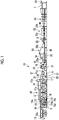
- Fig. 1 is a schematic view illustrating a corrugating machine serving as a cardboard sheet-manufacturing apparatus of the present embodiment.
- the corrugating machine 10 serving as the cardboard sheet-manufacturing apparatus manufactures bonds, for example, a back liner C as a second liner to a corrugating medium (core paper) B subjected to waveform processing to manufacture a single-faced cardboard sheet D and bonds, for example, a front liner A as a first liner to a corrugating medium B side in the single-faced cardboard sheet D to manufacture a double-faced cardboard sheet E.
- bonds for example, a back liner C as a second liner to a corrugating medium (core paper) B subjected to waveform processing to manufacture a single-faced cardboard sheet D and bonds, for example, a front liner A as a first liner to a corrugating medium B side in the single-faced cardboard sheet D to manufacture a double-faced cardboard sheet E.
- the corrugating machine 10 has a mill roll stand 11 for the corrugating medium B, and a preheater (preheating unit) 12, a mill roll stand 13 for the back liner C, a preheater (preheating unit) 14, a single facer 15, a bridge 16, a mill roll stand 17 for the front liner A, a preheater (preheating unit) 18, a glue machine 19, a double facer 20, a printing unit 21, a rotary shear 22, a slitter scorer 23, a cutoff 24, and a stacker 25.
- Roll papers around which a core paper formed with the corrugating medium B is wound in the shape of a roll are respectively mounted on both sides of the mill roll stand 11, and a splicer (paper splicing unit) 11a that performs paper splicing is provided above the mill roll stand 11.
- a splicer paper splicing unit 11a that performs paper splicing is provided above the mill roll stand 11.
- the other roll paper is mounted and paper splicing preparation is performed. If a base paper of the one roll paper runs short, this paper is spliced to a base paper of the other roll paper by the splicer 11a. Then, while the base paper is supplied from the other roll paper, one roll paper is mounted and paper splicing preparation is performed. In this way, the base papers are sequentially spliced together, and are continuously delivered from the mill roll stand 11 toward a downstream side.
- roll papers around which the back liner C is wound in the shape of a roll are respectively mounted on both sides of the mill roll stand 13, and a splicer 13a that performs paper splicing is provided above the mill roll stand 13.
- the other roll paper is mounted and paper splicing preparation is performed. If a base paper of the one roll paper runs short, this paper is spliced to a base paper of the other roll paper by the splicer 13a. Then, while the base paper is supplied from the other roll paper, one roll paper is mounted and paper splicing preparation is performed. In this way, the base papers are sequentially spliced together, and are continuously delivered from the mill roll stand 13 toward the downstream side.
- the respective preheaters 12 and 14 preheat the corrugating medium B and the back liner C, respectively.
- Each of the preheaters 12 and 14 has a heating roll into which steam is supplied, and raises the temperature of the base paper (the corrugating medium B or the back liner C) continuously delivered from the mill roll stand 11 or 13 to a predetermined temperature by winding the base paper around the heating roll to transport the base paper.
- the single facer 15 has a pressing belt 15a, an upper stage roll 15b, and a lower stage roll 15c.
- the back liner C heated by the preheater 14 is transferred to a nip part between the pressing belt 15a and the upper stage roll 15b.
- the corrugating medium B heated by the preheater 12 is transferred to the nip part between the pressing belt 15a and the upper stage roll 15b after being processed wavelike by an engagement part between the upper stage roll 15b and the lower stage roll 15c.
- a gluing unit 15d is disposed in the vicinity of the upper stage roll 15b.
- the gluing unit 15d has a gluing roll that applies glue to the corrugating medium B.
- the corrugating medium B corrugated by the engagement part between the upper stage roll 15b and the lower stage roll 15c is glued at respective top parts of corrugations by the gluing unit 15d (gluing roll), and is bonded to the back liner C in the nip part between the pressing belt 15a and the upper stage roll 15b to form the single-faced cardboard sheet D.
- a take-up conveyor 31 is provided obliquely above the single facer 15 on the downstream side in a transport direction.
- the take-up conveyor 31 consists of a pair of endless belts, and has a function of sandwiching the single-faced cardboard sheet D formed in the single facer 15 to transport the single-faced cardboard sheet D to the bridge 16.
- the bridge 16 functions as a retention part that primarily retains the single-faced cardboard sheet D in order to absorb a speed difference between the single facer 15 and the double facer 20.
- Roll papers around which the front liner A is wound in the shape of a roll are respectively mounted on both sides of the mill roll stand 17, and a splicer 17a that performs paper splicing is provided above the mill roll stand 17.
- the other roll paper is mounted and paper splicing preparation is performed. If a base paper of the one roll paper runs short, this paper is spliced to a base paper of the other roll paper by the splicer 17a. Then, while the base paper is supplied from the other roll paper, one roll paper is mounted and paper splicing preparation is performed. In this way, the base papers are sequentially spliced together, and are continuously delivered from the mill roll stand 17 toward the downstream side.
- the preheater 18 has a heating roll 32 for single-faced cardboard sheet D (hereinafter referred to as a single-faced cardboard sheet heating roll), and a heating roll 33 for the front liner A (hereinafter referred to as a front liner heating roll).
- the single-faced cardboard sheet heating roll 32 has a winding amount adjusting unit, is heated to a predetermined temperature by supplying steam thereinto, and is capable of preheating the single-faced cardboard sheet D by the back liner C side of the single-faced cardboard sheet D being wound around a peripheral surface thereof.
- the front liner heating roll 33 also has a winding amount adjusting unit, is heated to a predetermined temperature by supplying steam thereinto, and is capable of preheating the front liner A by the front liner C being wound around a peripheral surface thereof.
- the glue machine 19 has a gluing unit and a pressing unit.
- the single-faced cardboard sheet D heated by the single-faced cardboard sheet heating roll 32 is guided into the glue machine 19 on the way, and is glued on the respective top parts of the corrugations of the corrugating medium B when passing between a rider roll and the gluing roll.
- the single-faced cardboard sheet D glued by the glue machine 19 is transferred to the double facer 20 of the next step. Additionally, the front liner A heated by the front liner heating roll 33 is also transferred to the double facer 20 through the glue machine 19.
- the double facer 20 is divided into an upstream heating section 20a and a downstream cooling section 20b along a traveling line of the single-faced cardboard sheet D and the front liner A.
- the single-faced cardboard sheet D glued by the glue machine 19 is carried in between a pressing belt 34 and a hot plate 35 in the heating section 20a, and the front liner A is carried in between the pressing belt 34 and the hot plate 35 so as to overlap the corrugating medium B side of the single-faced cardboard sheet D.
- the single-faced cardboard sheet D and the front liner A are carried in between the pressing belt 34 and the hot plate 35, are then integrated with each other in the state of overlapping each other, and are transferred toward the cooling section 20b.
- the single-faced cardboard sheet D and the front liner A are heated while being pressed, and are thereby bonded together to form a continuous double-faced cardboard sheet E.
- the double-faced cardboard sheet E is naturally cooled when being transported while being sandwiched between the pressing belt 34 and the transporting belt 36 in the cooling section 20b.
- the printing unit 21 is disposed between the mill roll stand 17 and the preheater 18 to invert the front liner A and print a pattern and a cutting mark on a front surface of the front liner.
- the printing unit 21 has a plurality of inverting guide rollers 37, an ink jet printer 38 serving as a digital printing machine (variable printing machine) that performs color printing, and a dryer 39 that dries ink.
- the digital printing machine is a plateless type printing machine, an electronic printing device or the like may be used, not limited to the ink jet printer 38, and a drawing method does not matter.
- the front liner A delivered from the mill roll stand 17 is temporarily inverted by the plurality of guide rollers 37 such that a front surface becomes an upper surface because a lower surface is the front surface.
- the ink jet printer 38 color-prints the pattern and the cutting mark on the front surface (upper surface) of the inverted front liner A. In this case, only the cutting mark may be printed without printing the pattern.
- the dryer 39 dries the pattern and the cutting mark (ink) that are printed on the front surface of the front liner A.
- the double-faced cardboard sheet E manufactured by the double facer 20 is transferred to the rotary shear 22.
- the rotary shear 22 cuts the double-faced cardboard sheet E over its full width or partially in a width direction in a case where bonding is stabilized in an initial operation stage.
- the slitter scorer 23 cuts a wide double-faced cardboard sheet E in the transport direction so as to have a predetermined width, and processes a ruled line that extends in the transport direction.
- the slitter scorer 23 consists of a first slitter scorer unit 23a and a second slitter scorer unit 23b that are arranged in the transport direction of the double-faced cardboard sheet E and have substantially the same structure.
- the first slitter scorer unit 23a and the second slitter scorer unit 23b have a plurality of pairs of upper ruled line rolls and lower ruled line rolls, which are disposed to face each other with double-faced cardboard sheet E therebetween, in the width direction, and have a plurality of slitter knives, which are disposed below the double-faced cardboard sheet E, in the width direction.
- the cutoff 24 cuts the double-faced cardboard sheet E, which is cut in the transport direction by the slitter scorer 23, in the width direction, and forms a plate-shaped double-faced cardboard sheet F with a predetermined length.
- the cutoff 24 receives and processes two double-faced cardboard sheets E, which are cut to the predetermined width in the transport direction in the slitter scorer 23, into two upper and lower stages, and both have substantially the same configuration.
- the cutoff 24 has a mark detector 40, and cuts the double-faced cardboard sheet E to the predetermined length in the width direction if the mark detector 40 detects the cutting mark printed on the double-faced cardboard sheet E (front liner A).
- the stacker 25 stacks the double-faced cardboard sheet F cut by the cutoff 24, and discharges the double-faced cardboard sheet F to the outside of the machine as a product.
- the cardboard sheet-cutting device of the present embodiment T is constituted by the printing unit 21, the slitter scorer (first cutting machine) 23, the cutoff (second cutting machine) 24, and the control unit, and if the mark detector 40 detects the cutting mark of the double-faced cardboard sheet E, the control unit is adapted to control the driving of the cutoff 24 to cut the double-faced cardboard sheet E to the predetermined length.
- control unit is adapted to move the mark detector 40 on the basis of job-change timing data and position information on the cutting mark after the job change.
- Fig. 2 is a schematic configuration view illustrating the cardboard sheet-cutting method of the present embodiment.
- the detected position of the cutting mark can be adjusted in the width direction of the double-faced cardboard sheet E as the mark detector 40 of the cutoff 24 is moved in the width direction of the double-faced cardboard sheet E by the movement unit 41.
- the printing unit 21 has a printing control unit 51 connected thereto, and the printing control unit 51 is adapted to be capable of controlling the driving of the printing unit 21.
- the slitter scorer 23 and the cutoff 24 are connected to the cutting control unit 52, and the cutting control unit 52 is adapted to be capable of controlling the driving of the slitter scorer 23 and the cutoff 24.
- the cutting control unit 52 has the mark detector 40 connected thereto, has information on the cutting mark detected by the mark detector 40 input thereto, and drives the cutoff 24 on the basis of this information.
- the cutting control unit 52 has the movement unit 41 connected thereof and drives the movement unit 41 on the basis of the job-change timing data and the position information on the cutting mark after the job change.
- the printing control unit 51 and the cutting control unit 52 are connected to each other, and is connected to a production management unit 53.
- the printing control unit 51 and the cutting control unit 52 are capable of exchanging data (information) with each other
- the production management unit 53 is capable of exchanging data (information) with the printing control unit 51 and the cutting control unit 52.
- the production management unit 53 has a data storage 54 connected thereof, and is capable of storing various kinds of input data or retrieving the stored data.
- the control unit of the present embodiment is constituted by the printing control unit 51, the cutting control unit 52, and the production management unit 53.
- An image of the pattern, an image of the cutting mark, printing positions of the pattern and the cutting mark, printing colors of the pattern and the cutting mark, and the cutting width and the cutting length of the double-faced cardboard sheet, which constitute some of the job data, are set as image data, and this image data is input to the printing control unit 51.
- the target manufactured sheet number (target printed sheet number) of double-faced cardboard sheets that constitutes some of the job data is set as production control data, and data of this target manufactured sheet number is input to the production management unit 53 and is stored in the data storage 54.
- the printing control unit 51 controls the driving of the printing unit 21 on the basis of the input image data, and prints the pattern and the cutting mark using predetermined colors at predetermined positions in the front liner A.
- the printing control unit 51 outputs the input image data to the cutting control unit 52, and the cutting control unit 52, controls the driving of the slitter scorer 23 to cut the double-faced cardboard sheet E to the predetermined width, on the basis of this image data, controls the driving of the cutoff 24 to cut the double-faced cardboard sheet E to the predetermined length, on the basis of the cutting mark detected by the mark detector 40.
- the production management unit 53 outputs the input production control data to the printing control unit 51, and the printing control unit 51 controls the driving of the printing unit 21 to print predetermined numbers of patterns and cutting marks on the front liner A, on the basis of this production control data.
- a plurality of kinds of the job data are input to the production management unit 53 and is stored in the data storage 54.
- the mark detector 40 is moved by the movement unit 41 on the basis of the job-change timing data and the position data information on the cutting mark after the job change.
- the job-change timing data is target manufactured sheet number data (target printed sheet number data) corresponding to a job under execution
- the printing control unit 51 switches from a printing operation of the cutting mark corresponding to a job under execution by the printing unit 21 to a printing operation of the cutting mark corresponding to the next job if an actual printed sheet number of the cutting mark corresponding to the job under execution reaches the target printed sheet number.
- the cutting control unit 52 moves the mark detector 40 by the movement unit 41 if a switching position of the cutting mark reaches the cutoff 24.
- the mark position information is printing position data of the cutting mark in a longitudinal direction of the double-faced cardboard sheet E, and the cutting control unit 52 moves the mark detector 40 to a cutting mark detectable position after a job change using the movement unit 41 if the switching position of the cutting mark reaches the cutoff 24.
- the production management unit 53 ascertains the printing end timing of the last cutting mark (printing end time) in a job under execution by the printing unit 21. Additionally, the production management unit 53 ascertains the time until the cutting mark (the switching position of the cutting mark) reaches the cutoff 24 from the distance from the printing unit 21 to the cutoff 24 and the transport speed of the double-faced cardboard sheet E. For that reason, the cutting control unit 52 can calculate the timing (reaching time) that the switching position of the cutting mark reaches the cutoff 24, using the data from the production management unit 53.
- the cutoff 24 may have a counter and may detect that the actual manufactured sheet number of the cutting mark corresponding to a job under execution reaches the target manufactured sheet number from the number of times of operation of the cutoff 24.
- the first job when the first job is changed to the second job, it is necessary to change the cutting width of the double-faced cardboard sheet E by the slitter scorer 23. Additionally, since it is necessary to change the cutting length of the double-faced cardboard sheet E by the cutoff 24, when the first job is changed to the second job, a switching time of the cutting positions of the slitter scorer 23 and the cutoff 24 are required. Additionally, in this case, the movement time for which the mark detector 40 is moved from the cutting mark detectable position in the first job to a cutting mark detectable position in the second job is required. For that reason, the double-faced cardboard sheet E runs idle while the switching time and the movement time elapse.
- the idle running length of the double-faced cardboard sheet E is set in correspondence with the switching time and the movement time (idle running period).
- the printing control unit 51 controls the printing timing of the printing unit 21 in accordance with the idle running length of the double-faced cardboard sheet E. That is, if the actual printed sheet number according to the first job reaches the target printed sheet number, the printing control unit 51 starts printing according to the second job after the idle running length (switching position) of the double-faced cardboard sheet E is left, that is, an idle running region where a product is not produced is provided.
- the idle running length of the double-faced cardboard sheet E is a fixed value.
- a prescribed idle running length may be set in consideration of the aforementioned switching time and movement time, the transport speed of the double-faced cardboard sheet E, and the like, and the idle running length may be set to one time, two times, or the like the prescribed idle running length W with respect to the cutting length by the cutoff 24 in each job.
- the mark detector 40 is, for example, a concentration sensor.
- the mark detector 40 measures the reflected light amount value from the front surface of the double-faced cardboard sheet E, and distinguishes an image line portion (solid printed portion) and a non-image line portion (blank portion) from each other on the basis of this reflected light amount value.
- the cutting control unit 52 has data of the cutting mark image (shape, dimension, color) in advance, and compares the length of the double-faced cardboard sheet E in the transport direction and the length of the cutting mark in the image line portion (solid printed portion) detected by the mark detector 40. Here, if the cutting control unit 52 determines that the detected image is the cutting mark, the double-faced cardboard sheet E is cut by the cutoff 24.
- the cutting control unit 52 corrects a detection result of the mark detector 40 on the basis of the printing color of the cutting mark. That is, although the mark detector 40 measures the value of amount of reflected light from the front surface of the double-faced cardboard sheet E and the cutting control unit 52 distinguishes the image line portion and the non-image line portion from each other on the basis of the reflected light amount value, this reflected light amount value fluctuates according to the printing color. For that reason, the cutting control unit 52 changes a determination value for distinguishing the image line portion and the non-image line portion according to the printing color. That is, the sensitivity of the mark detector 40 is adjusted according to the printing color.
- the mark detector 40 detects the image printed on the double-faced cardboard sheet E, and if the cutting control unit 52 determines that the detected image is the cutting mark, the double-faced cardboard sheet E is cut by the cutoff 24. However, if a detection error of the mark detector 40 or a determination error of the cutting control unit 52 occurs, the cutoff 24 does not cut the double-faced cardboard sheet E, and the double-faced cardboard sheet F longer (for example, 2 double length) than the predetermined length flows to the stacker 25, and a stacking detect occurs. For that reason, a cutting upper limit length obtained by adding a margin length to the cutting length of the double-faced cardboard sheet E is set.
- the cutting control unit 52 operates the cutoff 24 to cut the double-faced cardboard sheet E when the cutting mark exceeds the cutting upper limit length.
- data of the cutting length of the double-faced cardboard sheet F is input from the printing control unit 51 to the cutting control unit 52 on the basis of the cutting length of the image data.
- the cutting control unit 52 ascertains a transport length per a predetermined time from the transport speed of the double-faced cardboard sheet E. If the cutting control unit 52 determines the cutting mark beyond the predetermined time, the cutoff 24 is forcedly operated.
- the double-faced cardboard sheet E generated in correspondence with the idle running length of the double-faced cardboard sheet E becomes a defective double-faced cardboard sheet F. Since the production management unit 53 recognizes the idle running length of the double-faced cardboard sheet E, the cutoff 24 is forcedly operated if a region of the idle running length of this double-faced cardboard sheet E reaches the cutoff 24, a defective double-faced cardboard sheet F corresponding to the idle running length is removed from a transport line and is eliminated by a defect removal unit 26. Additionally, a defective double-faced cardboard sheet generated by forcedly operating the cutoff 24 is also eliminated by the defect removal unit 26 at the time of occurrence of a detection error of the mark detector 40 or a determination error of the cutting control unit 52.
- the printing unit 21 prints the pattern and the cutting mark on the front surface of the front liner A has been described.
- the pattern may be used as the cutting mark without printing an exclusive cutting mark.
- the front liner A having the pattern printed in advance on the front surface thereof may be used, and the printing unit 21 may print only the cutting mark in synchronization with the pattern printed in advance.
- the cutting length (target cutting length) of the double-faced cardboard sheet F is input from the printing control unit 51 to the production management unit 53
- the cutting length (actual cutting length) of the double-faced cardboard sheet F cut by operating the cutoff 24 from the cutting control unit 52 is input to the production management unit 53
- the production management unit 53 calculates and the deviation of the target cutting length and the actual cutting length of the double-faced cardboard sheet F. Then, the production management unit 53 corrects the printing data of the cutting mark using the printing unit 21 when the deviation between the target cutting length and the actual cutting length exceeds a preset allowable value.
- the double-faced cardboard sheet E is subjected to processing, such as heating, gluing, pressing, and the like until the single-faced cardboard sheet D and front liner A are transported to the cutoff 24 after being pasted together.
- elongation or contraction occurs due to surrounding environments (temperature and humidity) or the like.
- a distance between cutting marks when the printing unit 21 performs printing and a distance between cutting marks when the cutoff 24 performs cutting may be different from each other. For that reason the production management unit 53 corrects the printing dimension (for example, an enlargement ratio or a reduction ratio) of the cutting marks by the printing unit 21, when the deviation between the target cutting length and the actual cutting length exceeds the preset allowable value.
- FIG. 3 is a flowchart illustrating the cutting control during a job change
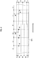
- Fig. 4 is a plan view for explaining the cutting positions of cardboard sheets during a job change.
- Step S11 an image of the pattern, an image of the cutting mark, printing positions of the pattern and the cutting mark, printing colors of the pattern and the cutting mark, and the cutting width and the cutting length of the double-faced cardboard sheet E, which constitute some of job data, which serve as image data (job data) are input to the printing control unit 51.
- Step S12 the manufactured sheet number (target manufactured sheet number) of double-faced cardboard sheets F serving as the production control data (job data) is input to the production management unit 53. In this case, a plurality of kinds of job data are input and stored in the data storage 54.
- Step S13 if a start command for a cardboard sheet manufacturing operation by the corrugating machine 10 is output to the production management unit 53 (Yes), cutting control is started by the printing control unit 51 and printing control is performed by the cutting control unit 52. On the other hand, if the start command for the cardboard sheet manufacturing operation by the corrugating machine 10 is not output to the production management unit 53 (No), the process stands by as it is.
- Step S21 the printing control unit 51 controls the printing unit 21, and the ink jet printer 38 prints the pattern and the cutting mark on the front surface of the front liner A on the basis of the job data.
- the cutting control unit 52 controls the slitter scorer 23 in Step S31 on the basis of the job data, and the slitter scorer 23 cuts the double-faced cardboard sheet E to the predetermined width in the transport direction.
- Step S32 the cutting control unit 52 determines the presence/absence of the cutting mark on the basis of the detection result from the mark detector 40.
- the cutoff 24 is controlled and the cutoff 24 cuts the double-faced cardboard sheet E to the predetermined length in the width direction to form the double-faced cardboard sheet F.
- Step S32 if the cutting control unit 52 does not detect the cutting mark (No), it is determined in Step S34 whether or not a length (double-faced cardboard sheet transport length) by which the double-faced cardboard sheet E is transported exceeds the cutting upper limit length after the cutoff 24 performs cutting.
- a length double-faced cardboard sheet transport length
- the process returns to Step S32.
- Step S33 if it is determined that the double-faced cardboard sheet transport length has exceeded the cutting upper limit length (Yes), in Step S33, a defective double-faced cardboard sheet F is formed as the cutoff 24 cuts the double-faced cardboard sheet E.
- Step S22 it is determined whether the actual number of sheets printed by the printing unit 21 has reached the target printed sheet number.
- the process returns to Step S21.
- Step S23 it is determined in Step S23 whether or not all the printing job is terminated.
- Step S24 the printing job is changed in Step S24.
- Step S25 the process returns to Step S21 after the idle running length of the double-faced cardboard sheet E is set, and the following printing job is executed.
- Step S23 if it is determined that all the printing job has been terminated (Yes), the printing operation is terminated.
- Step S35 it is determined whether or not the switching position (idle running length/non-printed region) of the cutting mark of the job under execution and the next job has reached the cutoff 24.
- the process returns to Step S31.
- Step S36 it is determined in Step S36 whether all the cutting jobs are terminated.
- Step S37 if it is determined that all cutting jobs are not terminated (No), a cutting job is changed in Step S37.
- Step S38 the process returns to Step S31 after the position of the mark detector 40 is changed, and the next cutting job is executed.
- Step S36 if it is determined that all the cutting job has been terminated (Yes), the printing operation is terminated.
- the first job is to cut a continuous double-faced cardboard sheet E to a trim width T1 from each end part in the width direction using the slitter scorer 23, cuts the continuous double-faced cardboard sheet E to a cutting width S1, and cuts the continuous double-faced cardboard sheet E to a cutting length L1 using the cutoff 24. Then, the first job is to print the cutting mark M at a position of the cutting length L1 and at a position of a width M1 from one end part in the width direction on the continuous double-faced cardboard sheet E.
- the second job is to cut the continuous double-faced cardboard sheet E to a trim width T2 from each end part in the width direction using the slitter scorer 23, cuts the continuous double-faced cardboard sheet E to a cutting width S2, and cuts the continuous double-faced cardboard sheet E to a cutting length L2 using the cutoff 24. Then, the second job is to print the cutting mark M at a position of the cutting length L2 and at a position of a width M2 from one end part in the width direction on the continuous double-faced cardboard sheet E. Then, an idle running length W of the continuous double-faced cardboard sheet E is set.
- the idle running length W is set to a length approximated to one sheet with the cutting length L2.
- the idle running length W is not limited this. Since a defective double-faced cardboard sheet F with the idle running length W is removed after being cut in the cutoff 24, for example, the idle running length W may be a length equivalent to a plurality of sheets to be cut by the cutoff 24.
- the cardboard sheet-cutting method of the present embodiment is provided with the printing unit 21 that prints the cutting mark M on the double-faced cardboard sheet E, the slitter scorer 23 that cuts the double-faced cardboard sheet E to the predetermined width, the cutoff 24 that cuts the double-faced cardboard sheet E to the predetermined length, the mark detector 40 that detects the cutting mark M in double-faced cardboard sheet E, and the cutting control unit 52 that changes a control setting value of the mark detector 40 on the basis of printing image information.
- the printing unit 21 prints the cutting mark M on the front liner A
- the slitter scorer 23 cuts the double-faced cardboard sheet E to the predetermined width in the longitudinal direction
- the mark detector 40 detects the cutting mark M
- the cutoff 24 cuts the double-faced cardboard sheet E to the predetermined length in the width direction.
- the cutting control unit 52 changes the setting value for controlling the mark detector 40.
- the printing image information is information for changing a printing image printed on the double-faced cardboard sheet E
- the cutting control unit 52 changes the control setting value of the mark detector 40 on the basis of the changed printing image. Therefore, a cutting operation can be continuously performed without stopping the transport of the double-faced cardboard sheet E.
- the movement unit 41 that moves the mark detector 40 in the width direction of the double-faced cardboard sheet E is provided, the printing image information is set to the cutting width, of the double-faced cardboard sheet E to be by the slitter scorer 23, which is changed with a change in the printing image, and the control setting value is set to a detected position detected by the mark detector 40.
- the cutting control unit 52 moves the mark detector 40 to a detected position after a change using the movement unit 41 on the basis of the changed cutting width of the double-faced cardboard sheet E. Therefore, a continuous cutting operation becomes possible without stopping the transport of the double-faced cardboard sheet E, the operation efficiency can be improved, and the production costs can be reduced by suppressing generation of waste paper.
- the printing image information is job change information in which the cutting width of the double-faced cardboard sheet E by the slitter scorer 23 is changed during the transport of the double-faced cardboard sheet E, and when there is a job change, the cutting control unit 52 moves the mark detector 40 using the movement unit 41 on the basis of the job-change timing data and the mark position information after the job change. Therefore, when there is a job change in which the cutting width of the double-faced cardboard sheet E by the slitter scorer 23 is changed, the cutting control unit 52 moves the mark detector 40 using the movement unit 41 on the basis of the job-change timing data and the mark position information after the job change.
- the cutting control unit 52 moves the mark detector 40 to a position based on the mark position information after the job change at a timing when there is the job change, with the double-faced cardboard sheet E transported. For that reason, during the job change in which the cutting width of the double-faced cardboard sheet E is changed, a continuous cutting operation becomes possible without stopping the transport of the double-faced cardboard sheet E, and the operation efficiency can be improved. Additionally, the mark detector 40 can be rapidly moved to a predetermined position during the job change, and the production costs can be reduced by suppressing generation of waste paper.
- the job-change timing data is data of a target printed sheet number in a predetermined job
- the printing control unit 51 switches from printing of the cutting mark M corresponding to a job under execution by the printing unit 21 to printing of the cutting mark M corresponding to the next job if an actual printed sheet number of the cutting mark M corresponding to the job under execution reaches the target printed sheet number, and moves the mark detector 40 using the movement unit 41 if the switching position of the cutting mark M reaches the cutoff 24. Therefore, a cutting operation can be continuously performed even after a job change without stopping the transport of the double-faced cardboard sheet E.
- the mark position information is printing position data of the cutting mark M in the longitudinal direction of the double-faced cardboard sheet E, and when there is a job change, the cutting control unit 52 moves the mark detector 40 to a cutting mark M detectable position after the job change using the movement unit 41. Therefore, a cutting operation of the double-faced cardboard sheet E can be continuously performed even after the job change.
- the idle running length of the double-faced cardboard sheet E is set in correspondence with a period for which the mark detector 40 moves from the detectable position in the first job to the detectable position in the second job, and when there is a job change, the printing control unit 51 controls the printing timing of the printing unit 21 in accordance with the idle running length W of the double-faced cardboard sheet E. Therefore, a waste paper length corresponding to the idle running length W of the double-faced cardboard sheet E is defined by the cutting mark M. As a result, non-defective products and defective products can be appropriately sorted, and the waste paper length of the double-faced cardboard sheet E can be made as short as possible.
- an image of the cutting mark M, and the printing position of the cutting mark M, the printing color of the cutting mark M, the cutting width and the cutting length of the double-faced cardboard sheet E and the manufactured sheet number of double-faced cardboard sheet F are set as the job data. Therefore, the printing control unit 51 controls the printing unit 21 on the basis of the job data, and the cutting control unit 52 controls the slitter scorer 23, the cutoff 24, and the movement unit 41. Therefore, the printing of the cutting mark M onto the front liner A, the cutting of the double-faced cardboard sheet E, and the movement of the mark detector 40 are performed on the basis of the job data. As a result, the control can be simplified.
- the cutting upper limit length obtained by adding the margin length to the cutting length of the double-faced cardboard sheet E is set.
- the cutting control unit 52 operates the cutoff 24 when the cutting mark exceeds the cutting upper limit length. Therefore, even if a detection error of the cutting mark M by the mark detector 40 occurs, a continuous double-faced cardboard sheet E is not transported to the stacker 25 side, and there is no adverse effect on stacking, discharging, or the like of double-faced cardboard sheets F.
- the cutting control unit 52 corrects a detection result of the mark detector 40 on the basis of the printing color of the cutting mark M. Therefore, it is possible to eliminate non-detection of the mark detector 40 resulting from a shade change in the cutting mark M to improve detection accuracy.
- the cutting control unit 52 calculates the deviation between the target cutting length and the actual cutting length of the double-faced cardboard sheet E. Therefore, the cutting accuracy of the double-faced cardboard sheet F can be confirmed from the deviation between the target cutting length and the actual cutting length of the double-faced cardboard sheet E.
- the cutting control unit 52 corrects the printing data of the cutting mark M by the printing unit 21, when the deviation between the target cutting length and the actual cutting length of the double-faced cardboard sheet E exceeds a preset allowable value. Therefore, the printing position of the cutting mark M by the printing unit 21 can be changed in accordance with elongation or contraction of the double-faced cardboard sheet E, and the cutting accuracy of the double-faced cardboard sheet F can be improved.
- the printing unit 21 can print the pattern on the double-faced cardboard sheet E under transport, and uses at least a portion of the pattern as the cutting mark M. Therefore, it is not necessary to print an exclusive cutting mark M, and printing costs can be reduced.
- the operation of the cutoff 24 is controlled on the basis of a detection result of the mark detector 40, and when there is a job change in which the cutting width of the double-faced cardboard sheet F is changed, the mark detector 40 is moved by the movement unit 41 on the basis of the job-change timing data and the mark position information after the job change.
- the mark detector 40 is moved by the movement unit 41 on the basis of the job-change timing data and the mark position information after the job change. For that reason, during the job change in which the cutting width of the double-faced cardboard sheet E is changed, a continuous cutting operation becomes possible without stopping the transport of the double-faced cardboard sheet E, and the operation efficiency can be improved. Additionally, the mark detector 40 can be rapidly moved to a predetermined position during the job change, and the production costs can be reduced by suppressing generation of waste paper.
- the cardboard sheet-manufacturing apparatus of the present embodiment is provided with the single facer 15 that bonds the back liner C to the core paper (corrugating medium B) subjected to the waveform processing to manufacture the single-faced cardboard sheet D, and the double facer 20 that bonds the front liner A to the corrugating medium B side in the single-faced cardboard sheet D manufactured by the single facer 15 to manufacture the double-faced cardboard sheet E and is provided with the cutting control unit 52 that controls the operation of the cutoff 24 on the basis of a detection result of the mark detector 40 and moves the mark detector 40 using the movement unit 41 on the basis of the job-change timing data and the mark position information after the job change when there is job change in which the cutting width of the double-faced cardboard sheet F is changed.
- the single facer 15 bonds the back liner C to the core paper (corrugating medium B) subjected to the waveform processing to manufacture the single-faced cardboard sheet D
- the double facer 20 bonds the front liner A to the corrugating medium B side in the single-faced cardboard sheet D to manufacture the double-faced cardboard sheet E.
- the printing unit 21 prints the cutting mark M on the front liner A
- the slitter scorer 23 cuts the double-faced cardboard sheet E to the predetermined width in the longitudinal direction
- the mark detector 40 detects the cutting mark M
- the cutoff 24 cuts the double-faced cardboard sheet E to the predetermined length in the width direction.
- the mark detector 40 is moved by the movement unit 41 on the basis of the job-change timing data and the mark position information after the job change. That is, the cutting control unit 52 moves the mark detector 40 to a position based on the mark position information after the job change at a timing when there is the job change, with the double-faced cardboard sheet E transported. For that reason, during the job change in which the cutting width of the double-faced cardboard sheet E is changed, a continuous cutting operation becomes possible without stopping the transport of the double-faced cardboard sheet E, and the operation efficiency can be improved. Additionally, the mark detector 40 can be rapidly moved to a predetermined position during the job change, and the production costs can be reduced by suppressing generation of waste paper.
- the above-described embodiment is configured such that the concentration sensor is used as the mark detector 40, the image line portion and the non-image line portion are distinguished from each other in accordance with the value of amount of reflected light from the front surface of the double-faced cardboard sheet E, and the presence/absence of the cutting mark M is determined.
- the invention is not limited to this configuration.
- various sensors such as a laser sensor, CCD cameras, or the like, may be applied instead of the concentration sensor.
- the above-described embodiment is configured such that the cutting marks M are printed at the positions of the cutting lengths L1 and L2 and at the positions of the widths M1 and M2 from an end part in the width direction of the double-faced cardboard sheet E.
- the printing positions of the cutting marks M are not limited to these positions.
- the cutting marks M may be printed at positions shifted in the length direction of the double-faced cardboard sheet E from the positions of the cutting lengths L1 and L2.
- the number of printed cutting marks M is also not limited to one, and a plurality of cutting marks may be printed.
Landscapes
- Engineering & Computer Science (AREA)
- Mechanical Engineering (AREA)
- Life Sciences & Earth Sciences (AREA)
- Forests & Forestry (AREA)
- Computer Vision & Pattern Recognition (AREA)
- Machines For Manufacturing Corrugated Board In Mechanical Paper-Making Processes (AREA)
- Control Of Cutting Processes (AREA)
- Human Computer Interaction (AREA)
- Manufacturing & Machinery (AREA)
- Physics & Mathematics (AREA)
- General Physics & Mathematics (AREA)
- Automation & Control Theory (AREA)
Applications Claiming Priority (2)
| Application Number | Priority Date | Filing Date | Title |
|---|---|---|---|
| JP2015158372A JP6688575B2 (ja) | 2015-08-10 | 2015-08-10 | 段ボールシートの切断装置及びその切断制御装置並びに段ボールシートの製造装置 |
| PCT/JP2016/055489 WO2017026135A1 (ja) | 2015-08-10 | 2016-02-24 | 段ボールシートの切断装置及びその切断制御装置並びに段ボールシートの製造装置 |
Publications (3)
| Publication Number | Publication Date |
|---|---|
| EP3305486A1 EP3305486A1 (en) | 2018-04-11 |
| EP3305486A4 EP3305486A4 (en) | 2018-08-01 |
| EP3305486B1 true EP3305486B1 (en) | 2019-07-31 |
Family
ID=57983016
Family Applications (1)
| Application Number | Title | Priority Date | Filing Date |
|---|---|---|---|
| EP16834833.2A Active EP3305486B1 (en) | 2015-08-10 | 2016-02-24 | Cardboard sheet-cutting device, cutting control unit therefor, and cardboard sheet-manufacturing apparatus |
Country Status (6)
| Country | Link |
|---|---|
| US (1) | US10618190B2 (ja) |
| EP (1) | EP3305486B1 (ja) |
| JP (1) | JP6688575B2 (ja) |
| KR (1) | KR102128710B1 (ja) |
| CN (1) | CN108025448B (ja) |
| WO (1) | WO2017026135A1 (ja) |
Families Citing this family (25)
| Publication number | Priority date | Publication date | Assignee | Title |
|---|---|---|---|---|
| JP6688575B2 (ja) | 2015-08-10 | 2020-04-28 | 三菱重工機械システム株式会社 | 段ボールシートの切断装置及びその切断制御装置並びに段ボールシートの製造装置 |
| GB2542569B (en) * | 2015-09-22 | 2021-04-28 | Ds Smith Packaging Ltd | A combination of a printed roll and a print roll inventory map |
| WO2017131720A1 (en) | 2016-01-28 | 2017-08-03 | Hewlett-Packard Development Company, L.P. | Corrugator control information on a box liner |
| JP6732678B2 (ja) * | 2017-02-24 | 2020-07-29 | 三菱重工機械システム株式会社 | 段ボールウェブ裁断装置及び段ボール製造装置 |
| JP6939038B2 (ja) * | 2017-04-11 | 2021-09-22 | コニカミノルタ株式会社 | 画像形成システムおよび画像検査方法 |
| JP6273594B1 (ja) * | 2017-05-12 | 2018-02-07 | 三菱重工機械システム株式会社 | 段ボールシートの不良検出装置及び段ボールシートの不良除去装置並びに段ボールシートの製造装置 |
| US20190016551A1 (en) | 2017-07-14 | 2019-01-17 | Georgia-Pacific Corrugated, LLC | Reel editor for pre-print paper, sheet, and box manufacturing systems |
| US10642551B2 (en) | 2017-07-14 | 2020-05-05 | Georgia-Pacific Corrugated Llc | Engine for generating control plans for digital pre-print paper, sheet, and box manufacturing systems |
| US11449290B2 (en) | 2017-07-14 | 2022-09-20 | Georgia-Pacific Corrugated Llc | Control plan for paper, sheet, and box manufacturing systems |
| US11485101B2 (en) * | 2017-07-14 | 2022-11-01 | Georgia-Pacific Corrugated Llc | Controls for paper, sheet, and box manufacturing systems |
| US11520544B2 (en) | 2017-07-14 | 2022-12-06 | Georgia-Pacific Corrugated Llc | Waste determination for generating control plans for digital pre-print paper, sheet, and box manufacturing systems |
| DE102017216720A1 (de) * | 2017-09-21 | 2019-03-21 | Bhs Corrugated Maschinen- Und Anlagenbau Gmbh | Wellpappeanlage |
| US11472579B2 (en) | 2018-12-04 | 2022-10-18 | Gpcp Ip Holdings Llc | Film securing apparatus and method |
| CN108793713B (zh) * | 2018-06-27 | 2021-07-23 | 武汉华星光电技术有限公司 | 一种用于切割玻璃基板的切割机及玻璃基板的切割方法 |
| JP7187216B2 (ja) * | 2018-08-29 | 2022-12-12 | 三菱重工機械システム株式会社 | シートの不良除去装置及び方法並びに段ボールシートの製造装置 |
| CN110180642B (zh) * | 2019-05-31 | 2024-01-12 | 浙江理工大学 | 一种可将纸面有墨部分和无墨部分分离的碎纸装置 |
| IT201900019771A1 (it) * | 2019-10-25 | 2021-04-25 | Albert Zandonai | Macchina e metodo per il taglio di spezzoni da un nastro stampato |
| CN111070283B (zh) * | 2019-11-15 | 2022-04-12 | 武汉纺织大学 | 一种基于微秒级定时的计算机精密裁切纸板系统及方法 |
| JP7258742B2 (ja) * | 2019-12-27 | 2023-04-17 | 三菱重工機械システム株式会社 | インクジェット印刷装置およびコルゲートマシン |
| JP2021121480A (ja) * | 2020-01-31 | 2021-08-26 | 三菱重工機械システム株式会社 | コルゲートマシンの制御システム、コルゲートマシン、および、印刷装置の制御装置 |
| JP7267217B2 (ja) | 2020-01-31 | 2023-05-01 | 三菱重工機械システム株式会社 | インクジェット印刷装置、製函機およびコルゲートマシン |
| JP7413170B2 (ja) | 2020-07-15 | 2024-01-15 | 三菱重工機械システム株式会社 | 段ボールシートの不良検出装置および方法並びに段ボールシートの不良除去装置、段ボールシートの製造装置 |
| CN111736562B (zh) * | 2020-07-27 | 2020-12-15 | 广东佛斯伯智能设备有限公司 | 具有纸板长度控制及接头剔除功能的生产线的控制方法 |
| JP2022062735A (ja) * | 2020-10-09 | 2022-04-21 | コニカミノルタ株式会社 | 後処理システム、穿孔部材異常判定装置及びプログラム |
| US11685157B2 (en) * | 2021-07-12 | 2023-06-27 | Electronics For Imaging, Inc. | Upwards jetting digital printing platform |
Citations (9)
| Publication number | Priority date | Publication date | Assignee | Title |
|---|---|---|---|---|
| JPS59207251A (ja) | 1983-05-12 | 1984-11-24 | Dainippon Printing Co Ltd | オフセツト輪転印刷機における見当マ−ク検知用センサ−の位置決め方法 |
| DE4218764A1 (de) | 1992-06-06 | 1993-12-09 | Heidelberger Druckmasch Ag | Verfahren zur Positionierung eines Registermarkensensors an einer Bogendruckmaschine |
| WO1998009822A1 (en) | 1996-09-09 | 1998-03-12 | Fargo Electronics, Inc. | Label printer with cutter attachment |
| JP2002273800A (ja) | 2001-03-15 | 2002-09-25 | Rengo Co Ltd | 走行シートの切断位置制御装置 |
| JP2004082279A (ja) | 2002-08-27 | 2004-03-18 | Mitsubishi Heavy Ind Ltd | 印刷機の断裁制御装置及び断裁補助装置 |
| EP1459878A2 (de) | 2003-03-21 | 2004-09-22 | BHS Corrugated Maschinen-und Anlagenbau GmbH | Wellpappe-Anlage sowie Verfahren zur Herstellung von Wellpappe-Bögen |
| DE10331357A1 (de) | 2003-07-11 | 2005-01-27 | Bhs Corrugated Maschinen- Und Anlagenbau Gmbh | Wellpappe-Anlage |
| JP2007301662A (ja) | 2006-05-10 | 2007-11-22 | Rengo Co Ltd | 走行シートの切断位置検出装置 |
| WO2017026135A1 (ja) | 2015-08-10 | 2017-02-16 | 三菱重工印刷紙工機械株式会社 | 段ボールシートの切断装置及びその切断制御装置並びに段ボールシートの製造装置 |
Family Cites Families (13)
| Publication number | Priority date | Publication date | Assignee | Title |
|---|---|---|---|---|
| JPS4827674B1 (ja) * | 1969-09-17 | 1973-08-24 | ||
| JPS60217097A (ja) * | 1984-04-10 | 1985-10-30 | 株式会社 クラウン・パツケ−ジ | 段ボ−ルの切断方法 |
| JP3841580B2 (ja) * | 1999-01-12 | 2006-11-01 | レンゴー株式会社 | 段ボールシートの製造方法 |
| JP2003245894A (ja) * | 2002-02-21 | 2003-09-02 | Isowa Corp | 被検出体の撮像方法並びにコルゲートマシンのカッタにおける被検出体の検出装置及び段ボールシート製函機における被検出体の検出装置 |
| JP4554227B2 (ja) * | 2003-02-28 | 2010-09-29 | 株式会社Isowa | 連続シートの切断方法 |
| JP2005131955A (ja) * | 2003-10-30 | 2005-05-26 | Isowa Corp | 不良シート処理方法 |
| CN1872505A (zh) * | 2004-06-03 | 2006-12-06 | 富士胶片株式会社 | 喷墨用记录纸的制作方法 |
| JP4718980B2 (ja) * | 2005-12-02 | 2011-07-06 | 三菱重工印刷紙工機械株式会社 | コルゲートマシンおよびこれに用いる生産管理装置 |
| JP5199586B2 (ja) * | 2007-02-23 | 2013-05-15 | レンゴー株式会社 | 段ボールシート製造装置の蒸気加熱段ロールの加熱制御方法 |
| US8376516B2 (en) * | 2010-04-06 | 2013-02-19 | Xerox Corporation | System and method for operating a web printing system to compensate for dimensional changes in the web |
| JP5963073B2 (ja) | 2011-12-22 | 2016-08-03 | 住友化学株式会社 | 光学フィルムの切断方法および切断装置 |
| KR101459878B1 (ko) | 2013-02-07 | 2014-11-12 | 목성균 | 가스 주름관 연결장치 |
| CN103286812B (zh) * | 2013-05-23 | 2015-05-27 | 南京工业大学 | 一种横切机色标剪切方法 |
-
2015
- 2015-08-10 JP JP2015158372A patent/JP6688575B2/ja active Active
-
2016
- 2016-02-24 WO PCT/JP2016/055489 patent/WO2017026135A1/ja active Application Filing
- 2016-02-24 US US15/742,838 patent/US10618190B2/en active Active
- 2016-02-24 EP EP16834833.2A patent/EP3305486B1/en active Active
- 2016-02-24 CN CN201680040552.2A patent/CN108025448B/zh active Active
- 2016-02-24 KR KR1020187001018A patent/KR102128710B1/ko active IP Right Grant
Patent Citations (9)
| Publication number | Priority date | Publication date | Assignee | Title |
|---|---|---|---|---|
| JPS59207251A (ja) | 1983-05-12 | 1984-11-24 | Dainippon Printing Co Ltd | オフセツト輪転印刷機における見当マ−ク検知用センサ−の位置決め方法 |
| DE4218764A1 (de) | 1992-06-06 | 1993-12-09 | Heidelberger Druckmasch Ag | Verfahren zur Positionierung eines Registermarkensensors an einer Bogendruckmaschine |
| WO1998009822A1 (en) | 1996-09-09 | 1998-03-12 | Fargo Electronics, Inc. | Label printer with cutter attachment |
| JP2002273800A (ja) | 2001-03-15 | 2002-09-25 | Rengo Co Ltd | 走行シートの切断位置制御装置 |
| JP2004082279A (ja) | 2002-08-27 | 2004-03-18 | Mitsubishi Heavy Ind Ltd | 印刷機の断裁制御装置及び断裁補助装置 |
| EP1459878A2 (de) | 2003-03-21 | 2004-09-22 | BHS Corrugated Maschinen-und Anlagenbau GmbH | Wellpappe-Anlage sowie Verfahren zur Herstellung von Wellpappe-Bögen |
| DE10331357A1 (de) | 2003-07-11 | 2005-01-27 | Bhs Corrugated Maschinen- Und Anlagenbau Gmbh | Wellpappe-Anlage |
| JP2007301662A (ja) | 2006-05-10 | 2007-11-22 | Rengo Co Ltd | 走行シートの切断位置検出装置 |
| WO2017026135A1 (ja) | 2015-08-10 | 2017-02-16 | 三菱重工印刷紙工機械株式会社 | 段ボールシートの切断装置及びその切断制御装置並びに段ボールシートの製造装置 |
Also Published As
| Publication number | Publication date |
|---|---|
| WO2017026135A1 (ja) | 2017-02-16 |
| KR20180018701A (ko) | 2018-02-21 |
| EP3305486A4 (en) | 2018-08-01 |
| US10618190B2 (en) | 2020-04-14 |
| JP6688575B2 (ja) | 2020-04-28 |
| KR102128710B1 (ko) | 2020-07-01 |
| CN108025448A (zh) | 2018-05-11 |
| CN108025448B (zh) | 2020-08-28 |
| US20180200906A1 (en) | 2018-07-19 |
| JP2017035755A (ja) | 2017-02-16 |
| EP3305486A1 (en) | 2018-04-11 |
Similar Documents
| Publication | Publication Date | Title |
|---|---|---|
| EP3305486B1 (en) | Cardboard sheet-cutting device, cutting control unit therefor, and cardboard sheet-manufacturing apparatus | |
| EP3352981B1 (en) | Corrugated sheet processing apparatus | |
| JP4718981B2 (ja) | コルゲートマシンおよびこれに用いる生産管理装置 | |
| US11110680B2 (en) | Method of determining warp status for corrugated board | |
| JP2010017885A (ja) | 段ボールシートの製造装置 | |
| EP0733467B1 (en) | Laminator for corrugated paperboard sheets | |
| KR102196596B1 (ko) | 시트의 불량 제거 장치 및 방법, 시트의 불량 제거 제어 장치, 골판지 시트의 제조 장치 | |
| EP3042757B1 (en) | Device and method for preventing warping of double-faced corrugated cardboard sheet and manufacturing apparatus for double-faced corrugated cardboard sheet | |
| JP4718980B2 (ja) | コルゲートマシンおよびこれに用いる生産管理装置 | |
| JP2019177652A (ja) | 段ボールシートの製造装置 | |
| JP2007030178A (ja) | 段ボールシートの製造装置 | |
| JP2010017886A (ja) | 段ボールシートの製造装置 | |
| JP3905767B2 (ja) | 段ボールシートの反り矯正システム | |
| JP7133967B2 (ja) | 段ボールシートの切断システム及び方法並びに段ボールシートの製造装置 | |
| JP7187216B2 (ja) | シートの不良除去装置及び方法並びに段ボールシートの製造装置 | |
| JP2006062243A (ja) | 段ボールシートの製造装置 | |
| JP7181619B2 (ja) | シート材の位置調整方法 | |
| WO2022138570A1 (ja) | 段ボールシートの紙継ぎ部検出装置および段ボールシートの製造装置 | |
| WO2023131917A1 (en) | Plant and method for manufacturing corrugated board with an order change detector |
Legal Events
| Date | Code | Title | Description |
|---|---|---|---|
| STAA | Information on the status of an ep patent application or granted ep patent |
Free format text: STATUS: THE INTERNATIONAL PUBLICATION HAS BEEN MADE |
|
| PUAI | Public reference made under article 153(3) epc to a published international application that has entered the european phase |
Free format text: ORIGINAL CODE: 0009012 |
|
| STAA | Information on the status of an ep patent application or granted ep patent |
Free format text: STATUS: REQUEST FOR EXAMINATION WAS MADE |
|
| 17P | Request for examination filed |
Effective date: 20180105 |
|
| AK | Designated contracting states |
Kind code of ref document: A1 Designated state(s): AL AT BE BG CH CY CZ DE DK EE ES FI FR GB GR HR HU IE IS IT LI LT LU LV MC MK MT NL NO PL PT RO RS SE SI SK SM TR |
|
| AX | Request for extension of the european patent |
Extension state: BA ME |
|
| RIC1 | Information provided on ipc code assigned before grant |
Ipc: B26D 5/34 20060101ALI20180621BHEP Ipc: B26D 9/00 20060101ALI20180621BHEP Ipc: B26D 11/00 20060101ALI20180621BHEP Ipc: B26D 5/00 20060101AFI20180621BHEP Ipc: B31F 7/00 20060101ALI20180621BHEP |
|
| A4 | Supplementary search report drawn up and despatched |
Effective date: 20180629 |
|
| DAV | Request for validation of the european patent (deleted) | ||
| DAX | Request for extension of the european patent (deleted) | ||
| GRAP | Despatch of communication of intention to grant a patent |
Free format text: ORIGINAL CODE: EPIDOSNIGR1 |
|
| STAA | Information on the status of an ep patent application or granted ep patent |
Free format text: STATUS: GRANT OF PATENT IS INTENDED |
|
| RIC1 | Information provided on ipc code assigned before grant |
Ipc: B26D 5/34 20060101ALI20190325BHEP Ipc: B65H 35/08 20060101ALI20190325BHEP Ipc: B26D 9/00 20060101ALI20190325BHEP Ipc: B65H 29/12 20060101ALI20190325BHEP Ipc: B41J 11/70 20060101ALI20190325BHEP Ipc: B26D 11/00 20060101ALI20190325BHEP Ipc: B31F 5/04 20060101ALI20190325BHEP Ipc: B41J 11/66 20060101ALI20190325BHEP Ipc: B32B 37/20 20060101ALI20190325BHEP Ipc: G05B 19/18 20060101ALI20190325BHEP Ipc: B41J 11/68 20060101ALI20190325BHEP Ipc: B32B 38/00 20060101ALI20190325BHEP Ipc: B32B 29/00 20060101ALI20190325BHEP Ipc: B65H 43/08 20060101ALI20190325BHEP Ipc: B26D 5/00 20060101AFI20190325BHEP Ipc: B41J 11/00 20060101ALI20190325BHEP Ipc: B31F 7/00 20060101ALI20190325BHEP Ipc: B32B 41/00 20060101ALI20190325BHEP |
|
| INTG | Intention to grant announced |
Effective date: 20190411 |
|
| GRAS | Grant fee paid |
Free format text: ORIGINAL CODE: EPIDOSNIGR3 |
|
| GRAA | (expected) grant |
Free format text: ORIGINAL CODE: 0009210 |
|
| STAA | Information on the status of an ep patent application or granted ep patent |
Free format text: STATUS: THE PATENT HAS BEEN GRANTED |
|
| AK | Designated contracting states |
Kind code of ref document: B1 Designated state(s): AL AT BE BG CH CY CZ DE DK EE ES FI FR GB GR HR HU IE IS IT LI LT LU LV MC MK MT NL NO PL PT RO RS SE SI SK SM TR |
|
| REG | Reference to a national code |
Ref country code: CH Ref legal event code: EP Ref country code: GB Ref legal event code: FG4D |
|
| REG | Reference to a national code |
Ref country code: DE Ref legal event code: R096 Ref document number: 602016017898 Country of ref document: DE |
|
| REG | Reference to a national code |
Ref country code: AT Ref legal event code: REF Ref document number: 1160426 Country of ref document: AT Kind code of ref document: T Effective date: 20190815 |
|
| REG | Reference to a national code |
Ref country code: IE Ref legal event code: FG4D |
|
| REG | Reference to a national code |
Ref country code: NL Ref legal event code: MP Effective date: 20190731 |
|
| REG | Reference to a national code |
Ref country code: LT Ref legal event code: MG4D |
|
| REG | Reference to a national code |
Ref country code: AT Ref legal event code: MK05 Ref document number: 1160426 Country of ref document: AT Kind code of ref document: T Effective date: 20190731 |
|
| PG25 | Lapsed in a contracting state [announced via postgrant information from national office to epo] |
Ref country code: LT Free format text: LAPSE BECAUSE OF FAILURE TO SUBMIT A TRANSLATION OF THE DESCRIPTION OR TO PAY THE FEE WITHIN THE PRESCRIBED TIME-LIMIT Effective date: 20190731 Ref country code: NL Free format text: LAPSE BECAUSE OF FAILURE TO SUBMIT A TRANSLATION OF THE DESCRIPTION OR TO PAY THE FEE WITHIN THE PRESCRIBED TIME-LIMIT Effective date: 20190731 Ref country code: FI Free format text: LAPSE BECAUSE OF FAILURE TO SUBMIT A TRANSLATION OF THE DESCRIPTION OR TO PAY THE FEE WITHIN THE PRESCRIBED TIME-LIMIT Effective date: 20190731 Ref country code: NO Free format text: LAPSE BECAUSE OF FAILURE TO SUBMIT A TRANSLATION OF THE DESCRIPTION OR TO PAY THE FEE WITHIN THE PRESCRIBED TIME-LIMIT Effective date: 20191031 Ref country code: BG Free format text: LAPSE BECAUSE OF FAILURE TO SUBMIT A TRANSLATION OF THE DESCRIPTION OR TO PAY THE FEE WITHIN THE PRESCRIBED TIME-LIMIT Effective date: 20191031 Ref country code: AT Free format text: LAPSE BECAUSE OF FAILURE TO SUBMIT A TRANSLATION OF THE DESCRIPTION OR TO PAY THE FEE WITHIN THE PRESCRIBED TIME-LIMIT Effective date: 20190731 Ref country code: PT Free format text: LAPSE BECAUSE OF FAILURE TO SUBMIT A TRANSLATION OF THE DESCRIPTION OR TO PAY THE FEE WITHIN THE PRESCRIBED TIME-LIMIT Effective date: 20191202 Ref country code: SE Free format text: LAPSE BECAUSE OF FAILURE TO SUBMIT A TRANSLATION OF THE DESCRIPTION OR TO PAY THE FEE WITHIN THE PRESCRIBED TIME-LIMIT Effective date: 20190731 Ref country code: HR Free format text: LAPSE BECAUSE OF FAILURE TO SUBMIT A TRANSLATION OF THE DESCRIPTION OR TO PAY THE FEE WITHIN THE PRESCRIBED TIME-LIMIT Effective date: 20190731 |
|
| PG25 | Lapsed in a contracting state [announced via postgrant information from national office to epo] |
Ref country code: LV Free format text: LAPSE BECAUSE OF FAILURE TO SUBMIT A TRANSLATION OF THE DESCRIPTION OR TO PAY THE FEE WITHIN THE PRESCRIBED TIME-LIMIT Effective date: 20190731 Ref country code: IS Free format text: LAPSE BECAUSE OF FAILURE TO SUBMIT A TRANSLATION OF THE DESCRIPTION OR TO PAY THE FEE WITHIN THE PRESCRIBED TIME-LIMIT Effective date: 20191130 Ref country code: RS Free format text: LAPSE BECAUSE OF FAILURE TO SUBMIT A TRANSLATION OF THE DESCRIPTION OR TO PAY THE FEE WITHIN THE PRESCRIBED TIME-LIMIT Effective date: 20190731 Ref country code: AL Free format text: LAPSE BECAUSE OF FAILURE TO SUBMIT A TRANSLATION OF THE DESCRIPTION OR TO PAY THE FEE WITHIN THE PRESCRIBED TIME-LIMIT Effective date: 20190731 Ref country code: GR Free format text: LAPSE BECAUSE OF FAILURE TO SUBMIT A TRANSLATION OF THE DESCRIPTION OR TO PAY THE FEE WITHIN THE PRESCRIBED TIME-LIMIT Effective date: 20191101 Ref country code: ES Free format text: LAPSE BECAUSE OF FAILURE TO SUBMIT A TRANSLATION OF THE DESCRIPTION OR TO PAY THE FEE WITHIN THE PRESCRIBED TIME-LIMIT Effective date: 20190731 |
|
| PG25 | Lapsed in a contracting state [announced via postgrant information from national office to epo] |
Ref country code: TR Free format text: LAPSE BECAUSE OF FAILURE TO SUBMIT A TRANSLATION OF THE DESCRIPTION OR TO PAY THE FEE WITHIN THE PRESCRIBED TIME-LIMIT Effective date: 20190731 |
|
| REG | Reference to a national code |
Ref country code: DE Ref legal event code: R026 Ref document number: 602016017898 Country of ref document: DE |
|
| PG25 | Lapsed in a contracting state [announced via postgrant information from national office to epo] |
Ref country code: DK Free format text: LAPSE BECAUSE OF FAILURE TO SUBMIT A TRANSLATION OF THE DESCRIPTION OR TO PAY THE FEE WITHIN THE PRESCRIBED TIME-LIMIT Effective date: 20190731 Ref country code: EE Free format text: LAPSE BECAUSE OF FAILURE TO SUBMIT A TRANSLATION OF THE DESCRIPTION OR TO PAY THE FEE WITHIN THE PRESCRIBED TIME-LIMIT Effective date: 20190731 Ref country code: PL Free format text: LAPSE BECAUSE OF FAILURE TO SUBMIT A TRANSLATION OF THE DESCRIPTION OR TO PAY THE FEE WITHIN THE PRESCRIBED TIME-LIMIT Effective date: 20190731 Ref country code: RO Free format text: LAPSE BECAUSE OF FAILURE TO SUBMIT A TRANSLATION OF THE DESCRIPTION OR TO PAY THE FEE WITHIN THE PRESCRIBED TIME-LIMIT Effective date: 20190731 |
|
| PLBI | Opposition filed |
Free format text: ORIGINAL CODE: 0009260 |
|
| PG25 | Lapsed in a contracting state [announced via postgrant information from national office to epo] |
Ref country code: SM Free format text: LAPSE BECAUSE OF FAILURE TO SUBMIT A TRANSLATION OF THE DESCRIPTION OR TO PAY THE FEE WITHIN THE PRESCRIBED TIME-LIMIT Effective date: 20190731 Ref country code: IS Free format text: LAPSE BECAUSE OF FAILURE TO SUBMIT A TRANSLATION OF THE DESCRIPTION OR TO PAY THE FEE WITHIN THE PRESCRIBED TIME-LIMIT Effective date: 20200224 Ref country code: CZ Free format text: LAPSE BECAUSE OF FAILURE TO SUBMIT A TRANSLATION OF THE DESCRIPTION OR TO PAY THE FEE WITHIN THE PRESCRIBED TIME-LIMIT Effective date: 20190731 Ref country code: SK Free format text: LAPSE BECAUSE OF FAILURE TO SUBMIT A TRANSLATION OF THE DESCRIPTION OR TO PAY THE FEE WITHIN THE PRESCRIBED TIME-LIMIT Effective date: 20190731 |
|
| 26 | Opposition filed |
Opponent name: BHS CORRUGATED MASCHINEN- UND ANLAGENBAU GMBH Effective date: 20200424 |
|
| PLAX | Notice of opposition and request to file observation + time limit sent |
Free format text: ORIGINAL CODE: EPIDOSNOBS2 |
|
| PG2D | Information on lapse in contracting state deleted |
Ref country code: IS |
|
| PG25 | Lapsed in a contracting state [announced via postgrant information from national office to epo] |
Ref country code: IS Free format text: LAPSE BECAUSE OF FAILURE TO SUBMIT A TRANSLATION OF THE DESCRIPTION OR TO PAY THE FEE WITHIN THE PRESCRIBED TIME-LIMIT Effective date: 20191030 |
|
| PG25 | Lapsed in a contracting state [announced via postgrant information from national office to epo] |
Ref country code: SI Free format text: LAPSE BECAUSE OF FAILURE TO SUBMIT A TRANSLATION OF THE DESCRIPTION OR TO PAY THE FEE WITHIN THE PRESCRIBED TIME-LIMIT Effective date: 20190731 |
|
| REG | Reference to a national code |
Ref country code: CH Ref legal event code: PL |
|
| PLBB | Reply of patent proprietor to notice(s) of opposition received |
Free format text: ORIGINAL CODE: EPIDOSNOBS3 |
|
| GBPC | Gb: european patent ceased through non-payment of renewal fee |
Effective date: 20200224 |
|
| REG | Reference to a national code |
Ref country code: BE Ref legal event code: MM Effective date: 20200229 |
|
| PG25 | Lapsed in a contracting state [announced via postgrant information from national office to epo] |
Ref country code: MC Free format text: LAPSE BECAUSE OF FAILURE TO SUBMIT A TRANSLATION OF THE DESCRIPTION OR TO PAY THE FEE WITHIN THE PRESCRIBED TIME-LIMIT Effective date: 20190731 Ref country code: LU Free format text: LAPSE BECAUSE OF NON-PAYMENT OF DUE FEES Effective date: 20200224 |
|
| PG25 | Lapsed in a contracting state [announced via postgrant information from national office to epo] |
Ref country code: LI Free format text: LAPSE BECAUSE OF NON-PAYMENT OF DUE FEES Effective date: 20200229 Ref country code: CH Free format text: LAPSE BECAUSE OF NON-PAYMENT OF DUE FEES Effective date: 20200229 |
|
| PG25 | Lapsed in a contracting state [announced via postgrant information from national office to epo] |
Ref country code: FR Free format text: LAPSE BECAUSE OF NON-PAYMENT OF DUE FEES Effective date: 20200229 Ref country code: IE Free format text: LAPSE BECAUSE OF NON-PAYMENT OF DUE FEES Effective date: 20200224 Ref country code: GB Free format text: LAPSE BECAUSE OF NON-PAYMENT OF DUE FEES Effective date: 20200224 |
|
| PG25 | Lapsed in a contracting state [announced via postgrant information from national office to epo] |
Ref country code: BE Free format text: LAPSE BECAUSE OF NON-PAYMENT OF DUE FEES Effective date: 20200229 |
|
| PLCK | Communication despatched that opposition was rejected |
Free format text: ORIGINAL CODE: EPIDOSNREJ1 |
|
| PG25 | Lapsed in a contracting state [announced via postgrant information from national office to epo] |
Ref country code: MT Free format text: LAPSE BECAUSE OF FAILURE TO SUBMIT A TRANSLATION OF THE DESCRIPTION OR TO PAY THE FEE WITHIN THE PRESCRIBED TIME-LIMIT Effective date: 20190731 Ref country code: CY Free format text: LAPSE BECAUSE OF FAILURE TO SUBMIT A TRANSLATION OF THE DESCRIPTION OR TO PAY THE FEE WITHIN THE PRESCRIBED TIME-LIMIT Effective date: 20190731 |
|
| APBM | Appeal reference recorded |
Free format text: ORIGINAL CODE: EPIDOSNREFNO |
|
| APBP | Date of receipt of notice of appeal recorded |
Free format text: ORIGINAL CODE: EPIDOSNNOA2O |
|
| APAH | Appeal reference modified |
Free format text: ORIGINAL CODE: EPIDOSCREFNO |
|
| PG25 | Lapsed in a contracting state [announced via postgrant information from national office to epo] |
Ref country code: MK Free format text: LAPSE BECAUSE OF FAILURE TO SUBMIT A TRANSLATION OF THE DESCRIPTION OR TO PAY THE FEE WITHIN THE PRESCRIBED TIME-LIMIT Effective date: 20190731 |
|
| APBQ | Date of receipt of statement of grounds of appeal recorded |
Free format text: ORIGINAL CODE: EPIDOSNNOA3O |
|
| PGFP | Annual fee paid to national office [announced via postgrant information from national office to epo] |
Ref country code: IT Payment date: 20230110 Year of fee payment: 8 |
|
| P01 | Opt-out of the competence of the unified patent court (upc) registered |
Effective date: 20230522 |
|
| APBU | Appeal procedure closed |
Free format text: ORIGINAL CODE: EPIDOSNNOA9O |
|
| PGFP | Annual fee paid to national office [announced via postgrant information from national office to epo] |
Ref country code: DE Payment date: 20231229 Year of fee payment: 9 |