EP3301031B1 - Abdeckungsbeseitigungssystem zur verwendung in gehäusen mit kontrollierten umgebung - Google Patents
Abdeckungsbeseitigungssystem zur verwendung in gehäusen mit kontrollierten umgebung Download PDFInfo
- Publication number
- EP3301031B1 EP3301031B1 EP17185418.5A EP17185418A EP3301031B1 EP 3301031 B1 EP3301031 B1 EP 3301031B1 EP 17185418 A EP17185418 A EP 17185418A EP 3301031 B1 EP3301031 B1 EP 3301031B1
- Authority
- EP
- European Patent Office
- Prior art keywords
- gripping
- cover
- container
- gripping area
- tub
- Prior art date
- Legal status (The legal status is an assumption and is not a legal conclusion. Google has not performed a legal analysis and makes no representation as to the accuracy of the status listed.)
- Active
Links
Images


Classifications
-
- B—PERFORMING OPERATIONS; TRANSPORTING
- B67—OPENING, CLOSING OR CLEANING BOTTLES, JARS OR SIMILAR CONTAINERS; LIQUID HANDLING
- B67B—APPLYING CLOSURE MEMBERS TO BOTTLES JARS, OR SIMILAR CONTAINERS; OPENING CLOSED CONTAINERS
- B67B7/00—Hand- or power-operated devices for opening closed containers
- B67B7/14—Hand- or power-operated devices for opening closed containers for removing tightly-fitting lids or covers, e.g. of shoe-polish tins, by gripping and rotating
-
- B—PERFORMING OPERATIONS; TRANSPORTING
- B25—HAND TOOLS; PORTABLE POWER-DRIVEN TOOLS; MANIPULATORS
- B25J—MANIPULATORS; CHAMBERS PROVIDED WITH MANIPULATION DEVICES
- B25J11/00—Manipulators not otherwise provided for
-
- B—PERFORMING OPERATIONS; TRANSPORTING
- B25—HAND TOOLS; PORTABLE POWER-DRIVEN TOOLS; MANIPULATORS
- B25J—MANIPULATORS; CHAMBERS PROVIDED WITH MANIPULATION DEVICES
- B25J21/00—Chambers provided with manipulation devices
-
- B—PERFORMING OPERATIONS; TRANSPORTING
- B65—CONVEYING; PACKING; STORING; HANDLING THIN OR FILAMENTARY MATERIAL
- B65B—MACHINES, APPARATUS OR DEVICES FOR, OR METHODS OF, PACKAGING ARTICLES OR MATERIALS; UNPACKING
- B65B55/00—Preserving, protecting or purifying packages or package contents in association with packaging
- B65B55/02—Sterilising, e.g. of complete packages
- B65B55/027—Packaging in aseptic chambers
-
- B—PERFORMING OPERATIONS; TRANSPORTING
- B65—CONVEYING; PACKING; STORING; HANDLING THIN OR FILAMENTARY MATERIAL
- B65B—MACHINES, APPARATUS OR DEVICES FOR, OR METHODS OF, PACKAGING ARTICLES OR MATERIALS; UNPACKING
- B65B57/00—Automatic control, checking, warning, or safety devices
- B65B57/02—Automatic control, checking, warning, or safety devices responsive to absence, presence, abnormal feed, or misplacement of binding or wrapping material, containers, or packages
-
- B—PERFORMING OPERATIONS; TRANSPORTING
- B65—CONVEYING; PACKING; STORING; HANDLING THIN OR FILAMENTARY MATERIAL
- B65B—MACHINES, APPARATUS OR DEVICES FOR, OR METHODS OF, PACKAGING ARTICLES OR MATERIALS; UNPACKING
- B65B69/00—Unpacking of articles or materials, not otherwise provided for
-
- B—PERFORMING OPERATIONS; TRANSPORTING
- B67—OPENING, CLOSING OR CLEANING BOTTLES, JARS OR SIMILAR CONTAINERS; LIQUID HANDLING
- B67B—APPLYING CLOSURE MEMBERS TO BOTTLES JARS, OR SIMILAR CONTAINERS; OPENING CLOSED CONTAINERS
- B67B7/00—Hand- or power-operated devices for opening closed containers
- B67B7/38—Power-operated cutting devices
-
- G—PHYSICS
- G01—MEASURING; TESTING
- G01N—INVESTIGATING OR ANALYSING MATERIALS BY DETERMINING THEIR CHEMICAL OR PHYSICAL PROPERTIES
- G01N35/00—Automatic analysis not limited to methods or materials provided for in any single one of groups G01N1/00 - G01N33/00; Handling materials therefor
- G01N35/0099—Automatic analysis not limited to methods or materials provided for in any single one of groups G01N1/00 - G01N33/00; Handling materials therefor comprising robots or similar manipulators
-
- G—PHYSICS
- G01—MEASURING; TESTING
- G01N—INVESTIGATING OR ANALYSING MATERIALS BY DETERMINING THEIR CHEMICAL OR PHYSICAL PROPERTIES
- G01N35/00—Automatic analysis not limited to methods or materials provided for in any single one of groups G01N1/00 - G01N33/00; Handling materials therefor
- G01N2035/00178—Special arrangements of analysers
- G01N2035/00277—Special precautions to avoid contamination (e.g. enclosures, glove- boxes, sealed sample carriers, disposal of contaminated material)
-
- G—PHYSICS
- G01—MEASURING; TESTING
- G01N—INVESTIGATING OR ANALYSING MATERIALS BY DETERMINING THEIR CHEMICAL OR PHYSICAL PROPERTIES
- G01N35/00—Automatic analysis not limited to methods or materials provided for in any single one of groups G01N1/00 - G01N33/00; Handling materials therefor
- G01N35/02—Automatic analysis not limited to methods or materials provided for in any single one of groups G01N1/00 - G01N33/00; Handling materials therefor using a plurality of sample containers moved by a conveyor system past one or more treatment or analysis stations
- G01N35/04—Details of the conveyor system
- G01N2035/0401—Sample carriers, cuvettes or reaction vessels
- G01N2035/0403—Sample carriers with closing or sealing means
- G01N2035/0405—Sample carriers with closing or sealing means manipulating closing or opening means, e.g. stoppers, screw caps, lids or covers
Definitions
- This document relates generally to controlled environment enclosures and in particular to a method and apparatus for removing covers from sealed containers in controlled environment enclosures.
- Controlled environment enclosures are known in the art and are used, for example, for containment of hazardous materials or to provide controlled environments with limited numbers of particulates.
- controlled environment enclosures are typically fitted with ports for transfer of materials in and out of the enclosure and the ports are fitted with gloves for manual manipulation of equipment, parts or materials inside the enclosure.
- gloves are subject to significant risk of puncture, the consequences of which can be severe.
- the controlled environment enclosure is also used to limit exposure to viable particulates such a bacteria and fungi.
- the controlled environment enclosures may be required for aseptic processing of cell cultures or for the manufacture of pharmaceutical products, medical devices, food or food ingredients. In such applications the requirement is for the controlled environment enclosure to be decontaminated. This can be done thermally using steam or chemically using chemical agents. Suitable chemical agents known in the art include hydrogen peroxide, ozone, beta-propiolactone, aziridine, formaldehyde, chlorine dioxide, ethylene oxide, propylene oxide, and peracetic acid. In most cases the decontamination and sterilization operations have to be preceded by a cleaning process. Such cleaning processes have the function of removing major contamination by simple mechanical and chemical action.
- the controlled environment also contains automated equipment.
- automated equipment can include machines for manipulation of parts or as containers, including test tubes, roller bottles, cell culture dishes, bottles, vials, ampoules and syringes. Typical examples of such manipulations are inspection, filling and capping.
- Parts to be manipulated in controlled environment enclosures can be packaged in a container such as a tub.
- the container can be closed with a cover consisting of a sheet of flexible material, which generally is heat sealed to the container.
- the container and contents are decontaminated using a chemical agent, plasma or radiation.
- the automated equipment located in the controlled environment is typically of such a size and complexity that it cannot be operated fully automatically without human intervention.
- Such human intervention typically requires the use of gloves with the associated risk of puncture.
- a typical example of human intervention that involves the use of gloves is the removal of container covers.
- US2005/160704 A1 discloses a method and a device for removing a cover from a storage box that is closed using a lid-like cover attached thereto at the edges. For removal, the adhesive strength of the cover is reduced in the region of a few of the sealed edges and the cover is then removed by peeling it off the storage box, whereby the cover is peeled off by rolling it onto a roller.
- a method for removing within a controlled environment enclosure a container cover from a sealed container, the sealed container sealed by the container cover, the method comprising moving the container while holding a gripping area of the container cover substantially stationary.
- the moving of the container comprises holding the container with an articulated arm apparatus disposed within the controlled environment whilst removing the container cover by a first manipulation of the articulated arm apparatus.
- the method further comprises a second manipulating of the articulated arm apparatus to position along a trajectory the sealed container within a reach of a gripping apparatus disposed within the controlled environment, and gripping the gripping area with the gripping apparatus.
- the positioning of the sealed container comprises placing the gripping area of the container cover between two gripping elements of the gripping apparatus, the first and second of the two gripping elements respectively comprising first and second mutually parallel and mutually engagable grip surfaces.
- the method further comprises rotating at least one of the gripping elements.
- the positioning of the gripping area can comprise placing the gripping area proximate and substantially facing the first grip surface.
- the rotating of at least one of the gripping elements can comprise moving the second of the two gripping elements in a plane substantially parallel to the first grip surface.
- the positioning of the container can further comprise straightening the gripping area if the gripping area is bent toward the first grip surface by contacting to the first grip surface to one of the gripping area and a part of the cover in contact with the gripping area.
- the moving of the the second gripping element can comprise straightening the gripping area if the gripping area is bent toward the second gripping element by contacting the second grip surface to the other of the gripping area and the part of the cover in contact with the gripping area.
- the method can further comprise lowering the container or rotating the container about an axis substantially in the plane of the cover. This is done by a third manipulating of the articulated arm apparatus.
- the rotating or raising of the gripping area is to an extent that allows the gripping apparatus to remain clear of the container during the removing the container cover.
- the removing the container cover can be removing the container cover simultaneously along two edges of the container.
- the first manipulating of the articulated arm apparatus can comprise moving the container with respect to the gripping apparatus.
- Moving the container with respect to the gripping apparatus can comprise moving the container substantially diagonally with respect to the gripping apparatus.
- the moving the container with respect to the gripping apparatus can comprise moving the container along a predetermined path within a predetermined space..
- One or both of the predetermined path and the predetermined space can be determined using a controller.
- the predetermined path can be a circular path.
- the trajectory of the container can be based on information obtained from a sensor.
- the information can comprise one or both of position information and orientation information about the gripping area.
- the method can further comprise inspecting the container cover using a sensor.
- the method can further comprise selecting an alternative gripping area of the container cover based on the inspecting; gripping the alternative gripping area with the gripping apparatus; and removing the container cover by moving the container.
- the method can further comprise moving the gripping apparatus away from an operational area of the articulated arm apparatus after removing the container cover.
- an apparatus comprising a controlled environment enclosure; and within the controlled environment enclosure an articulated arm apparatus and a rotary gripping apparatus.
- the articulated arm apparatus can be configurable for holding and moving a container in three dimensions; and the rotary gripping apparatus can be configured for gripping a gripping area of a container cover sealing the container.
- the rotary gripping apparatus can comprise two gripping elements having facing mutually engagable surfaces, at least one of the two gripping elements being rotatable about a common axis with the other of the two gripping elements to grip the gripping area of the container cover between the two facing mutually engagable surfaces.
- the the articulated arm apparatus can comprise at least two arm segments, at least one arm segment being configurable to hold the container.
- the articulated arm apparatus and the rotary gripping apparatus can be separated by a distance large enough for the gripping apparatus to not interefere with the working of the articulated arm apparatus.
- the apparatus can further comprise a controller for controlling at least the articulated arm apparatus and the gripping apparatus.
- the moving the container can be moving the container along a path that is determined by the controller and the moving the container is contained within a space determined by the controller.
- the apparatus can further comprise a sensor configured for supplying information to the controller for determining at least one of a location of the container cover gripping area and an orientation of the container cover.
- the articulated arm apparatus can be at least one of automatically controlled and reprogrammable.
- the gripping apparatus can be at least one of automatically controlled and reprogrammable.
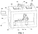
- FIG. 1 shows an apparatus 100 comprising a controlled environment enclosure 120, a gripping apparatus 113 and an articulated arm apparatus 115, both inside the controlled environment enclosure 120 and arranged for positioning and relocation of a container 114 within the controlled environment enclosure 120 without requiring direct human intervention and the associated use of gloves.
- Container 114 can be, for example, a tub.
- the term "tub" as used herein is used to describe any container suitable for holding parts, trays of nested arrangements of parts, a stack of trays with nested arrangements of parts, or combinations thereof.
- the apparatus 100 can further comprise of a sensor 160 for sensing the container 114.
- the controlled environment enclosure 120 can comprise windows 121 , an inlet filter 130 , an inlet valve 131 , a blower 132 , an outlet filter 133 and an outlet valve 134 .
- the characteristics of blower 132 , inlet filter 130, and outlet filter 133 are chosen to yield a controlled environment inside controlled environment enclosure 120 .
- the contents of the controlled environment enclosure 120 can be protected by airflow while having one or more openings (not shown).
- controlled environment enclosure 120 can be fully sealed and be operated at a positive or negative pressure differential relative to the surroundings.
- filters and blower arrangements can be used to establish a controlled environment inside controlled environment enclosure 120 .
- a suitable controlled environment can be obtained, for example without limitation, by means of any one or more of turbulent airflow, horizontal unidirectional airflow and vertical unidirectional airflow.
- the operation of the gripping apparatus 113 and the articulated arm apparatus 115 is controlled by a means located outside of environment enclosure 120 .
- the means of controlling apparatus 113 , apparatus 115 and enclosure 120 require a local or remote operator input device such as joy stick control, push button control, emergency stop, touch screen human machine interface, keyboard, mouse, handheld device or the like.
- a controller 140 Typically one or more of such input devices are connected to a controller 140 .
- a laptop computer programmed with suitable software is shown as an example of controller 140 .
- controller 140 can be a variety of other means such as operator interface panel, programmable logic controller, programmable automation controller, a desktop computer or a remote I/O module with embedded logic functions.
- the controller 140 can consist of a plurality of the aformentioned controllers.
- Control line 150 is a schematic representation of all of the required mechanical linkages, electrical wiring, pneumatic, hydraulic and wireless connections to operate apparatus 100.
- the container 114 can be manipulated inside the controlled environment enclosure 120 by mechanical means, for example, an articulated arm apparatus 115.
- Suitable robotic arm manipulation systems for mechanically manipulating the container 114 include, but are not limited to, 6-axis robotic arms, Selective Compliant Articulated Robot Arm (SCARA) systems, r-theta robots, and assemblies of linear actuators and rotary actuators, or combinations thereof.
- SCARA Selective Compliant Articulated Robot Arm
- the articulated arm apparatus 115 can by the articulated arm apparatus described in US Provisional Patent Application 61/596,698 .
- the controlled environment enclosure 120 includes a sensor 160 for sensing the container 114 and a container cover 116 for the container 114.
- the sensor is mounted to the top surface of the controlled environment enclosure 120. In other embodiments it can be mounted at another suitable location to monitor the interior of controlled environment enclosure 120.
- the sensor 160 in one example is an optical sensor. In other examples the sensor 160 can be one of a variety of other types of sensors, such as a camera system, a laser system or an ultrasonic sensing system. In yet other examples the sensor 160 is an assembly that consists of a plurality of sensing elements.
- the sensor 160 has a sensing cone (not shown) or multiple sensing cones than can cover a small, a large area or both; depending on the characteristics of the sensor 160 used.
- the controlled environment chamber 120 contains articulated arm apparatus 115 plus at least one further articulated arm apparatus (not shown in the interest of clarity).
- the additional at least one further articulated arm apparatus can be used, for example, for activities that can follow removal of the container cover 116 from the container 114.
- Apparatus 100 can be used for functions preceding the function of the filling system described in US patent application 12/393,183 .
- gripping apparatus 113 is added to a filling system as described in United States Patent Application 61/033,682 , with element 30 of United States Patent Application 61/033,682 as the equivalent of articulated arm apparatus 115 of the present specification, chamber 20 of United States Patent Application 61/033,682 as the equivalent of controlled environment enclosure 120 of the present specification, and optical sensor 12 of United States Patent Application 61/033,682 as the equivalent of sensor 160 of the present specification.
- the articulation of arm apparatus 115 can be remoted operated by the operator.
- the articulated arm apparatus 115 can be an automatically controlled articulated arm.
- the articulated arm apparatus can be a reprogrammable automatically controlled articulated arm.
- FIG. 2 shows a bottom view of an example of the container 114.
- the container 114 can be made of a metal, glass, plastic or a composite material, but typically the tub 114 is a single use thin walled container. Thin walled single use containers are typically made by a low cost process, such as thermoforming or injection molding. As shown in FIG 2 , the container 114 can have features such as tapered sidewalls that assist in manufacturability, but are more difficult to hold than an object with rigid parallel walls. All four walls forming the sides of the container 114 can have a step 201.
- FIG. 3 shows a detail view of container 114.
- the kind of container 114 typically employed in the pharmaceutical industry is characterized by a top lip 302 that provides a surface area for a sealed connection to the container cover 116.
- the term "cover” is used here to describe any surface material, including but not limited to a flexible sheet made of plastic material, a polymeric membrane or an impermeable laminated foil.
- the container cover 116 can extend outside the outline of the top lip 302 of the tub 114 in at least one location, and typically extends outside the outline of the top lip 302 in a plurality of locations.
- the at least one area of container cover 116 that extends outside the outline of the top lip 302 provides a gripping area 301 that can be used as access for clamping. Clamping on the gripping area 301 can be complicated by the flexibility of the material of the container cover 116.
- the gripping area 301 can be level, bent upwards, or bent downwards.
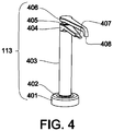
- FIG 4 shows an example embodiment of the gripping apparatus 113.
- An upper arm 406 is rotatably connected to a main shaft 403 by a radial seal 405.
- the main shaft 403 is rigidly connected to a lower arm 404 by a fully sealed joint.
- the main shaft 403 is rotatably connected to a base flange 401 by a radial seal 402.
- the base flange 401 is sealably connected to controlled environment enclosure 120.
- the tip of lower arm 404 and the tip of upper arm 406 have mutually facing and mutually engagable grip surfaces 407 and 408 respectively such that the mutually facing flat grip surfaces 407 and 408 are mutually engagable in the absence of any material, such as container cover material, being disposed between the surfaces.
- the grip surface 407 can be an upper surface of the tip of lower arm 404 and the grip surface 408 can be a lower surface of the tip of the upper arm 406.
- the lower arm 404 is stationary and upper arm 406 is rotatable about a cylindrical axis of main shaft 403.
- the upper arm 406 is stationary and lower arm 404 is rotatable about the cylindrical axis of main shaft 403 .
- both upper arm 406 and lower arm 404 are rotatable about the cylindrical axis of main shaft 403 .
- the gripping apparatus 113 can be remotely operated by the operator. In another embodiment the gripping apparatus 113 can be automatically controlled. In yet another embodiment the gripping appartatus 113 can be a reprogrammable automatically controlled gripping apparatus.
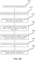
- FIG.9A , FIG.9B , FIG.9C , FIG.10A , FIG.10B, FIG.10C and FIG.11 a method for using the apparatus 100 to remove the cover 116 of the container 114 .
- the method comprises using the sensor 160 to detect an orientation of the gripping area 301 , and to communicate with the controller 140 over control line 150 .
- the method further comprises planning the trajectory of the container 114 using the controller 140 so that gripping apparatus 113 can access the gripping area 301 .
- the method comprises the sensor 160 sensing [510] information concerning the gripping area 301 and communicating [512] the sensed infomation to the controller 140 over control line 150 .
- the sensed information can be the position of the gripping area 301 or the orientation of gripping area 301 or both.
- the sensed infomation can be used as input information by the controller 140 for determining [514] a trajectory for the articulated arm apparatus 115 along which to position the sealed container 114 within a reach of the gripping apparatus 113.
- the cover gripping sequence can be initiated by rotating [520] the upper arm 406 and the lower arm 404 of the gripping apparatus 113 with respect to each other by an angle that separates the mutually facing grip surfaces 407 and 408 located on respectively lower arm 404 and upper arm 406 by at least the width of the container 114 . This can be done by rotating one or both of the arms 406 and 404.
- the method further comprises manipulating [530] articulated arm apparatus 115 to move the container 114 along the trajectory that places the gripping area 301 above the grip surface 407 of the lower arm 404 .
- This has the result of moving [532] the container 114 towards the lower arm 404 in a trajectory that results in a bottom surface of the top lip 302 of container 114 nearing or contacting the grip surface 407 of the lower arm 404 .
- the container 114 can be moved to cause the bottom surface of the top lip 302 to substantially slide along the grip surface 407 of the lower arm 404 .
- the tip of the lower arm 404 can be bending [534] the gripping area 301 upward in the case where gripping area 301 happens to be orientated downward to below the top lip 302 .
- the method further comprises rotating [540] upper arm 406 to grip the gripping area 301 .
- This comprises moving [542] the tip of upper arm 406 comprising the surface 408 over the container cover 116 during its travel to the gripping area 301 .
- the tip of the upper arm 406 can be bending [544] down to a substantially horizontal orientation any upward bent parts of cover 116 , including specifically the gripping area 301 .
- the senor 160 also senses the orientation of the gripping area 301 and communicates the sensed orientation to the controller 140 over control line 150 .
- the sensed orientation of the gripping area 301 can, as before, be used as input information by controller 140 to determine a trajectory for the articulated arm apparatus 115 along which to position the sealed container 114 within a reach of the gripping apparatus 113 .
- the cover gripping sequence can, as above, be initiated with the rotating [550] of the upper arm 406 and the lower arm 404 of the gripping apparatus 113 with respect to each other by an angle that separates the mutually facing grip surfaces 407 and 408 located on respectively lower arm 404 and upper arm 406 by at least the width of the container 114 .
- the method further comprises manipulating [560] articulated arm apparatus 115 to move the container 114 along the trajectory that places the gripping area 301 below the grip surface 408 of the upper arm 406.
- This has the result of moving [562] the container 114 towards the upper arm 406 in a trajectory that results in a top surface of the top lip 302 of container 114 , covered by cover 116 , nearing or contacting the grip surface 408 of the upper arm 406.
- the container 114 can be moved to cause the top surface of the top lip 302, covered by cover 116 , to substantially slide along the surface 408 of the upper arm 406.
- the tip of the upper arm 406 can be bending [564] the gripping area 301 downward in the case where gripping area 301 happens to be orientated upward to above the top lip 302 .
- the method further comprises rotating [570] the lower arm 404 to grip the gripping area 301 .
- This comprises moving [572] the tip of lower arm 404 comprising the grip surface 407 under the bottom surface of top lip 302 during its travel to the gripping area 301 .
- the tip of the lower arm 404 can be bending [574] up to a substantially horizontal orientation any downward bent parts of cover 116 , including specifically the gripping area 301 .
- the gripping apparatus 113 works for a wide range of thickness of the container cover 116 by clamping the gripping area 301 of container cover 116 in between the mutually facing grip surfaces 407 and 408 located on respectively the lower arm 404 and the upper arm 406 .
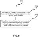
- the method provides for removing [580] the container cover 116 in the controlled environment enclosure 420. This is shown in expanded form in FIG.11 .
- the method can proceed further with manipulating [582] the articulated arm apparatus 120 to either lower the container 114 or rotate the container 114 about an axis substantially in the plane of the cover.
- This manipulating [582] is to a degree that positions and/or orients the container 114 and cover 116 such that clearance is established for the two arms 404 and 406 of the gripping apparatus 113 to clear the cover 116 and container 114 during the subsequent removal of the cover 116 from the container 114 .
- the container cover 116 can be removed by moving the container 114 in a substantially diagonal trajectory by manipulating [584] articulated arm apparatus 115 while the gripping apparatus 113 is holding the gripping area 301 substantially stationary.
- the term "substantially diagonal is used in this specification to describe a direction of motion parrallel to the diagional of the container 114 between the two sides of the container 114 that teminate jointly at the location of the gripping area 301.
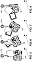
- the substantially diagonal trajectory minimizes a total length of adhesive that is being opened at any given time. As shown in FIGS 5-8 , the substantially diagonal trajectory can be obtained by rotating the articulated arm apparatus 115 in direction A.
- the controller 140 can be configured for predetermining the small space before the motion is conducted by predetermining the path for the container 114 to follow while being held by the articulated arm apparatus 115 .
- the predetermined path can be, but is not limited to, a cicular path.
- the container cover 116 can be removed by a more general direction of motion of container 114 by manipulating [584] articulated arm apparatus 115 while the gripping apparatus 113 is holding the gripping araea 301 substantially stationary.
- the articulated arm apparatus 115 is not limited to being rotated. This motion of the container 114 can be executed in a fashion and direction such as to remove the container cover 116 simultaneously along two edges of the container 114 , starting from the gripping area 301 .
- FIGS 5-8 provide an example of removal of the container cover 116 by a pushing motion of articulated arm apparatus 115 .
- the container cover 116 can be removed in a pulling motion by articulated arm apparatus 115 .
- the sensor 160 can be used for verifying the completeness of removal of the container cover 116 . If, for some undetermined reason, the gripping apparatus 113 were to lose its grip on the container cover 116 during the removal of the container cover 116, the articulated arm apparatus 115 can continue moving the container 114 with the partially removed container cover 116. In the event of such partial removal of container cover 116; the previously described process of orienting substantially horizontally any up-or downward bent areas of the cover 116, including the gripping area 301, can be repeated after the articulated arm apparatus 115 repositions the gripping area 301 near the tip of the lower arm 404.
- the process of gripping the gripping area 301 can be repeated after redirecting the articulated arm apparatus 115 to another suitable available gripping area 301.
- the manipulating [584] of the articulated arm apparatus 115 to remove the cover 116 as a "first manipulation”
- the manipulating [530] and [560] of the articulated arm apparatus 115 to position the container 114 between the lower arm 402 and the upper arm 406 as a "second manipulating”
- the gripping apparatus 113 is not limited to the example shown in FIG 4 .
- the gripping apparatus 113 can comprise a pair of prongs with narrow gap in between, one of which slides over and the other slides under the gripping area, thereby clamping the cover by friction caused by rotation of both prongs.
- the gripper can be of the type described in German Patent DE4419475 .
- the gripper apparatus can comprise gripping devices that are commercially available, such as parallel grippers, angular grippers or inflatable bellow grippers.
Landscapes
- Engineering & Computer Science (AREA)
- Mechanical Engineering (AREA)
- Robotics (AREA)
- Physics & Mathematics (AREA)
- Health & Medical Sciences (AREA)
- Life Sciences & Earth Sciences (AREA)
- Chemical & Material Sciences (AREA)
- Analytical Chemistry (AREA)
- Biochemistry (AREA)
- General Health & Medical Sciences (AREA)
- General Physics & Mathematics (AREA)
- Immunology (AREA)
- Pathology (AREA)
- Manipulator (AREA)
- Automatic Analysis And Handling Materials Therefor (AREA)
Claims (14)
- Verfahren zum Entfernen einer Abdeckung (116) von einem abgedichteten pharmazeutischen Becher (114) innerhalb einer Einfassung (120) mit kontrollierter Umgebung, die zum Aufrechterhalten einer aseptischen Bedingung fähig ist, wobei der abgedichtete Becher (114) durch die Abdeckung (116) abgedichtet ist,
dadurch gekennzeichnet, dass das Verfahren das Abziehen der Abdeckung (116) von dem Becher (114) durch Bewegen des Bechers (114), während ein Greifbereich (301) der Abdeckung (116) im Wesentlichen ortsfest gehalten wird, umfasst. - Verfahren nach Anspruch 1, gekennzeichnet durch Herstellen eines Druckdifferentials zwischen einem Inneren und einem Äußeren der Einfassung (120) vor dem Abziehen der Abdeckung.
- Verfahren nach Anspruch 2, gekennzeichnet durch Bereitstellen von gefilterter Luft an ein Inneres der Einfassung (120) vor dem Herstellen eines Druckdifferentials.
- Verfahren nach Anspruch 1, wobei das Entfernen der Behälterabdeckung (116) das Entfernen der Behälterabdeckung (116) gleichzeitig entlang zweier Ränder des Behälters (114) ist.
- Verfahren nach einem der vorhergehenden Ansprüche, gekennzeichnet durch Positionieren des Bechers (114), indem ein Greifbereich (301) der Abdeckung (116) zwischen zwei Greifelemente einer Greifvorrichtung (113) platziert wird, wobei das erste und das zweite der beiden Greifelemente jeweils eine erste und eine zweite Greiffläche (407, 408) umfassen, die zueinander parallel sind und sich gegenseitig in Eingriff nehmen können, und wahlweise oder vorzugsweise ferner umfassend das Drehen mindestens eines der Greifelemente und wahlweise oder vorzugsweise wobei das Positionieren des Greifbereichs (301) zwischen den beiden Greifelementen das Platzieren des Greifbereichs (301) in der Nähe der ersten Greiffläche (407) und dieser im Wesentlichen zugewandt umfasst, und wahlweise oder vorzugsweise wobei das Drehen mindestens eines der Greifelemente das Bewegen des zweiten der zwei Greifelemente in einer im Wesentlichen parallel zu der ersten Greiffläche (407) verlaufenden Ebene umfasst und wahlweise oder vorzugsweise wobei das Positionieren ferner das Geraderichten des Greifbereichs (301) umfasst, wenn der Greifbereich (301) zu der ersten Greiffläche hin gebogen ist, indem die erste Greiffläche (407) mit dem Greifbereich (301) oder einem mit dem Greifbereich (301) in Kontakt stehenden Teil der Abdeckung (116) in Kontakt gebracht wird, und wahlweise oder vorzugsweise wobei das Bewegen des zweiten Greifelements das Geraderichten des Greifbereichs (301) umfasst, wenn der Greifbereich (301) zu der zweiten Greiffläche hin gebogen ist, indem die zweite Greiffläche (408) mit dem jeweils anderen des Greifbereichs (301) oder des mit dem Greifbereich (301) in Kontakt stehenden Teils der Abdeckung (116) in Kontakt gebracht wird.
- Verfahren nach einem der vorhergehenden Ansprüche, wobei das Bewegen des Bechers (114) bezüglich der Greifvorrichtung (113) das Bewegen des Bechers (114) entlang einer vorbestimmten Bahn innerhalb eines vorbestimmten Raums umfasst und wahlweise oder vorzugsweise wobei die vorbestimmte Bahn und/oder der vorbestimmte Raum unter Verwendung einer Steuerung (140) bestimmt wird und wahlweise oder vorzugsweise wobei die vorbestimmte Bahn eine kreisförmige Bahn ist.
- Verfahren nach einem der vorhergehenden Ansprüche, wobei die vorbestimmte Bahn auf Informationen basiert, die von einem Sensor (160) erhalten worden sind, und wahlweise oder vorzugsweise wobei die Informationen Positionsinformationen und/oder Ausrichtungsinformationen über den Greifbereich (301) umfassen.
- Verfahren nach einem der vorhergehenden Ansprüche, ferner umfassend Inspizieren des Bechers (116) unter Verwendung eines Sensors (160) und wahlweise oder vorzugsweise
Wählen eines alternativen Greifbereichs (301) des Bechers (116) auf der Grundlage der Inspektion, Ergreifen des alternativen Greifbereichs (301) mit der Greifvorrichtung (113) und
Entfernen der Behälterabdeckung (116) durch Bewegen des Behälters (114). - Verfahren nach Anspruch 1, gekennzeichnet durch Herstellen einer aseptischen Bedingung in der Einfassung.
- Verfahren nach Anspruch 1, gekennzeichnet durch Dekontaminieren mindestens eines Abschnitts des Inneren der Einfassung.
- Vorrichtung zum Abziehen einer Abdeckung (116) von einem von der Abdeckung abgedichteten pharmazeutisehen Becher (114), wobei die Vorrichtung Folgendes umfasst:eine Einfassung (120) mit kontrollierter Umgebung, die dazu ausgestaltet ist, in einem Inneren der Einfassung einen Luftdruck aufrechtzuerhalten, der sich von einem außerhalb der Einfassung herrschenden Luftdruck unterscheidet,einen Luftfilter (130) in Fluidverbindung mit einem Inneren der Einfassung, wobei der Filter dazu ausgestaltet ist, im Inneren der Einfassung durch den Filter gefilterte Luft bereitzustellen, undin der Einfassung (120) mit kontrollierter Umgebung einen Greifer, der dazu angeordnet und ausgestaltet ist, einen Greifbereich der Abdeckung (116) zu ergreifen und auf eine im Wesentlichen ortsfeste Art zu halten, dadurch gekennzeichnet,dass die Vorrichtung in der Einfassung mit kontrollierter Umgebung ferner eine Greifvorrichtung (113) umfasst, die dazu angeordnet und ausgestaltet ist, den pharmazeutischen Becher in Eingriff zu nehmen und den Becher zu bewegen, um die Abdeckung von dem Becher abzuziehen, während die Greifvorrichtung den Greifbereich der Abdeckung im Wesentlichen ortsfest hält.
- Vorrichtung nach Anspruch 11, wobei die Drehgreifvorrichtung (113) zwei Greifelemente mit Flächen (407, 408) umfasst, die sich gegenüberliegen und sich gegenseitig in Eingriff nehmen können, wobei mindestens eines der beiden Greifelemente mit dem anderen der beiden Greifelemente um eine gemeinsame Achse drehbar ist, um den Greifbereich (301) der Abdeckung (116) zwischen den beiden Flächen (407, 408), die sich gegenüberliegen und sich gegenseitig in Eingriff nehmen können, zu ergreifen.
- Vorrichtung nach Anspruch 12, ferner umfassend eine Steuerung (140) zum Steuern mindestens der Greifvorrichtung (113) und wahlweise oder vorzugsweise wobei das Bewegen des Behälters (114) das Bewegen des Behälters (114) entlang einer durch die Steuerung (140) bestimmten Bahn ist und das Bewegen des Behälters (114) innerhalb eines durch die Steuerung (140) bestimmten Raums eingegrenzt ist und wahlweise oder vorzugweise ferner umfassend einen Sensor (160), der dazu konfiguriert ist, die Steuerung (140) zum Bestimmen eines Orts des Behälterabdeckungsgreifbereichs (301) und/oder einer Ausrichtung der Behälterabdeckung (116) mit Informationen zu versorgen.
- Vorrichtung nach Anspruch 13, wobei die Greifvorrichtung (113) automatisch gesteuert und/oder umprogrammierbar ist.
Applications Claiming Priority (3)
| Application Number | Priority Date | Filing Date | Title |
|---|---|---|---|
| US201261642430P | 2012-05-03 | 2012-05-03 | |
| PCT/US2013/039455 WO2013166379A1 (en) | 2012-05-03 | 2013-05-03 | Cover removal system for use in controlled environment enclosures |
| EP13785147.3A EP2844564B1 (de) | 2012-05-03 | 2013-05-03 | Haubenentfernungssystem zur verwendung in gehäusen in einer gesteuerten umgebung |
Related Parent Applications (1)
| Application Number | Title | Priority Date | Filing Date |
|---|---|---|---|
| EP13785147.3A Division EP2844564B1 (de) | 2012-05-03 | 2013-05-03 | Haubenentfernungssystem zur verwendung in gehäusen in einer gesteuerten umgebung |
Publications (2)
| Publication Number | Publication Date |
|---|---|
| EP3301031A1 EP3301031A1 (de) | 2018-04-04 |
| EP3301031B1 true EP3301031B1 (de) | 2019-07-03 |
Family
ID=49514908
Family Applications (2)
| Application Number | Title | Priority Date | Filing Date |
|---|---|---|---|
| EP17185418.5A Active EP3301031B1 (de) | 2012-05-03 | 2013-05-03 | Abdeckungsbeseitigungssystem zur verwendung in gehäusen mit kontrollierten umgebung |
| EP13785147.3A Active EP2844564B1 (de) | 2012-05-03 | 2013-05-03 | Haubenentfernungssystem zur verwendung in gehäusen in einer gesteuerten umgebung |
Family Applications After (1)
| Application Number | Title | Priority Date | Filing Date |
|---|---|---|---|
| EP13785147.3A Active EP2844564B1 (de) | 2012-05-03 | 2013-05-03 | Haubenentfernungssystem zur verwendung in gehäusen in einer gesteuerten umgebung |
Country Status (8)
| Country | Link |
|---|---|
| US (3) | US10081527B2 (de) |
| EP (2) | EP3301031B1 (de) |
| KR (1) | KR101917642B1 (de) |
| CA (1) | CA2911282C (de) |
| DK (2) | DK2844564T3 (de) |
| ES (2) | ES2643052T3 (de) |
| IN (1) | IN2014DN10204A (de) |
| WO (1) | WO2013166379A1 (de) |
Families Citing this family (39)
| Publication number | Priority date | Publication date | Assignee | Title |
|---|---|---|---|---|
| US10259607B2 (en) * | 2008-03-04 | 2019-04-16 | Vanrx Pharmasystems Inc. | Aseptic robotic filling system and method |
| EP3301031B1 (de) * | 2012-05-03 | 2019-07-03 | Vanrx Pharmasystems Inc. | Abdeckungsbeseitigungssystem zur verwendung in gehäusen mit kontrollierten umgebung |
| US12065347B2 (en) | 2012-05-03 | 2024-08-20 | Vanrx Pharmasystems Inc. | Cover removal system for use in controlled environment enclosures |
| US20250091752A1 (en) * | 2012-05-03 | 2025-03-20 | Vanrx Pharmasystems Inc. | Cover removal system for use in controlled environment enclosures |
| US12157595B2 (en) * | 2012-05-03 | 2024-12-03 | Vanrx Pharmasystems Inc. | Cover removal system for use in controlled environment enclosures |
| ITBO20120581A1 (it) * | 2012-10-25 | 2014-04-26 | Marchesini Group Spa | Metodo per rimuovere la pellicola di sigillatura da un contenitore e dispositivo che attua tale metodo |
| KR102444072B1 (ko) * | 2014-06-23 | 2022-09-16 | 펫 노베이션스 엘티디. | 동물 사료 공급 시스템 |
| JP6361822B2 (ja) * | 2015-05-11 | 2018-07-25 | 村田機械株式会社 | 自動運転機器システム、非常停止端末、及び操作端末の制御方法 |
| US10788264B2 (en) | 2016-04-12 | 2020-09-29 | Vanrx Pharmasystems, Inc. | Method and apparatus for loading a lyophilization system |
| IT201600074164A1 (it) * | 2016-07-15 | 2018-01-15 | Nuova Ompi Srl | Metodo di manipolazione di contenitori primari per uso farmaceutico trasportati lungo una linea automatica di trattamento operante in ambiente controllato |
| IT201600078059A1 (it) * | 2016-07-26 | 2018-01-26 | I M A Industria Macch Automatiche S P A In Sigla Ima S P A | Gruppo di apertura per confezioni |
| US10850873B2 (en) * | 2016-08-04 | 2020-12-01 | Vanrx Pharmasystems Inc. | Apparatus and method for asepticaly filling pharmaceutical containers with a pharmaceutical fluid using rotary stage |
| TW201811292A (zh) * | 2016-09-13 | 2018-04-01 | 加拿大商凡爾克斯醫藥系統公司 | 用於監控及控制使用旋轉台將藥物液體無菌裝填及密封於藥物容器的方法及裝置 |
| CA3077526A1 (en) | 2017-10-10 | 2019-04-18 | Vanrx Pharmasystems Inc. | Apparatus and method for monitoring and controlling the filling of a container with a pharmaceutical fluid in an aseptic environment |
| US10435287B2 (en) * | 2017-11-02 | 2019-10-08 | Marketech International Corp. | Automatic cover-opening and connector-replacing device for chemical container |
| US10955429B1 (en) * | 2017-12-06 | 2021-03-23 | National Technology & Engineering Solutions Of Sandia, Llc | Inspection workcell |
| US11230400B2 (en) | 2018-05-07 | 2022-01-25 | V Anrx Pharmasystems Inc. | Method, device and system for filling pharmaceutical containers |
| US20190368033A1 (en) * | 2018-06-05 | 2019-12-05 | United Technologies Corporation | Selective vapor deposition process for additive manufacturing |
| CH715184A1 (de) | 2018-07-18 | 2020-01-31 | Pharma Integration S R L | Anordnung zum kontaminationsfreien Einschleusen eines sterilen Objektes aus einem Behältnis in ein Containment und Verfahren dazu. |
| WO2020106744A1 (en) * | 2018-11-19 | 2020-05-28 | Diamond Onions | Apparatus and method for positioning an object |
| CH715871B1 (de) * | 2019-02-21 | 2023-10-13 | Smartpetcare Ag | Vorrichtung, insbesondere Haustierfütterungsvorrichtung und Verfahren zum Bereitstellen und Öffnen gefüllter Behälter. |
| DE102019002234A1 (de) | 2019-03-28 | 2020-10-01 | Gehring E-Tech Gmbh | Imprägniervorrichtung zur Träufelimprägnierung eines Strators einer Elektromaschine |
| US11014697B2 (en) * | 2019-06-03 | 2021-05-25 | Vanrx Pharmasystems Inc. | Peristaltic pump-based apparatus and method for the controlled dispensing of fluids |
| DE102019214849A1 (de) * | 2019-09-27 | 2021-04-01 | Bausch + Ströbel Maschinenfabrik Ilshofen GmbH + Co. KG | Produktionseinrichtung, insbesondere für die pharmaindustrie |
| CN110721986A (zh) | 2019-11-15 | 2020-01-24 | 楚天科技股份有限公司 | 一种去内膜装置及其去内膜方法 |
| US20210171231A1 (en) * | 2019-12-09 | 2021-06-10 | Revessel Inc | Robotic automated filling and capping system for vape oil cartridges |
| DE102019134550B4 (de) * | 2019-12-16 | 2021-07-22 | Benjamin List | Vorrichtung zur selbsttätigen bereitstellung von nassfutter für haustiere |
| CN113735037B (zh) * | 2020-05-29 | 2023-10-20 | 深圳迈瑞生物医疗电子股份有限公司 | 用于从样本管去除盖的密闭去盖装置及方法 |
| US11981473B2 (en) | 2020-09-27 | 2024-05-14 | V Anrx Pharmasystems Inc. | Cover removal system for use in controlled environment enclosures |
| KR102895321B1 (ko) | 2020-11-05 | 2025-12-05 | 삼성디스플레이 주식회사 | 필름 박리 장치 및 필름 박리 방법 |
| CN116568402A (zh) * | 2020-12-07 | 2023-08-08 | 柏业公司 | 导电性移液管安装用适配器、样品管开闭装置及样品自动分析系统 |
| TWI814360B (zh) * | 2022-04-27 | 2023-09-01 | 博訊生物科技股份有限公司 | 用於分子檢驗的核酸萃取裝置、方法及撕膜機構 |
| US12522814B2 (en) | 2022-07-21 | 2026-01-13 | Drsignal Biotechnology Co., Ltd. | Film-flipping mechanism for molecular testing, nucleic acid extraction device with the same, and nucleic acid extraction method for molecular testing |
| DE102023102479A1 (de) * | 2023-02-01 | 2024-08-01 | Syntegon Technology Gmbh | Handhabungssystem für einen Reinraum, ein Reinraum und ein Verfahren zum Abheben von Deckschichten |
| CN120712224A (zh) | 2023-02-21 | 2025-09-26 | 凡尔克斯医药系统公司 | 用于填充药物容器的方法、装置和系统 |
| WO2025058833A2 (en) | 2023-09-12 | 2025-03-20 | Vanrx Pharmasystems Inc. | System and method for discarding of peeled covers of pharmaceutical materials tubs under aseptic conditions |
| WO2025210090A1 (en) | 2024-04-03 | 2025-10-09 | Vanrx Pharmasystems Inc | Method, device and system for aseptically transferring nested pharmaceutical containers and closures |
| WO2025257109A1 (en) * | 2024-06-10 | 2025-12-18 | Merck Patent Gmbh | Automated membrane transfer system and process |
| EP4685062A1 (de) * | 2024-07-22 | 2026-01-28 | TT Innovation AG | Ausschleusevorrichtung und verfahren zur ausschleusung von abfallmaterial |
Family Cites Families (75)
| Publication number | Priority date | Publication date | Assignee | Title |
|---|---|---|---|---|
| US2735602A (en) * | 1956-02-21 | Apparatus for unseating milk can covers | ||
| FR488636A (fr) * | 1918-10-28 | 1918-10-23 | Antoine Mouneyrat | Caisse anaérobie |
| US2694324A (en) * | 1952-12-01 | 1954-11-16 | Vernon H Goldsmith | Wall attached jar lid remover with diagonal brace |
| US2995883A (en) * | 1960-07-05 | 1961-08-15 | Owens Illinois Glass Co | Removing temporary seals from containers |
| NL298177A (de) | 1963-01-30 | |||
| US4901504A (en) * | 1987-04-13 | 1990-02-20 | Mitsubishi Jukogyo Kabushiki Kaisha | Filling and casing system |
| US5341854A (en) * | 1989-09-28 | 1994-08-30 | Alberta Research Council | Robotic drug dispensing system |
| DE3936210A1 (de) * | 1989-10-31 | 1991-05-02 | Krupp Gmbh | Handhabungsvorrichtung zum be- und entdeckeln von normfaessern |
| US5313858A (en) * | 1993-03-08 | 1994-05-24 | Midwest Research Institute | Rubber stopper remover |
| US5370019A (en) * | 1994-01-10 | 1994-12-06 | Sartell; M. Kevin | Jar lid remover |
| DE4419475C2 (de) * | 1994-06-03 | 2002-04-04 | Inova Pharma Systems Gmbh | Einrichtung zum Entfernen der Abdeckung von Magazinkästen |
| JP2642317B2 (ja) * | 1994-08-03 | 1997-08-20 | ソマール株式会社 | フィルム剥離方法及び装置 |
| US5657617A (en) * | 1996-01-25 | 1997-08-19 | Komag, Incorporated | Shipping cassette lid and unlid automation |
| DE19604100C2 (de) * | 1996-02-06 | 1997-12-18 | Bosch Gmbh Robert | Vorrichtung zum Handhaben von in einem nach oben offenen Behälter angeordneten, befüllbaren, rohrförmigen Gegenständen |
| KR100543024B1 (ko) * | 1998-01-21 | 2006-05-25 | 삼성전자주식회사 | 액정표시장치의 편광판 제거장치 |
| US6159368A (en) * | 1998-10-29 | 2000-12-12 | The Perkin-Elmer Corporation | Multi-well microfiltration apparatus |
| US6309603B1 (en) * | 1999-02-01 | 2001-10-30 | Drummond Scientific Company | Microcentrifuge tube cap opening and closing apparatus and method |
| KR100383265B1 (ko) * | 2001-01-17 | 2003-05-09 | 삼성전자주식회사 | 웨이퍼 보호 테이프 제거용 반도체 제조장치 |
| WO2002096755A1 (en) * | 2001-05-30 | 2002-12-05 | United States Postal Service | Automatic lidder and/or un-lidder system and method |
| US6983721B2 (en) * | 2001-10-19 | 2006-01-10 | Hydropac/Lab Products, Inc. | Method and system of providing sealed bags of fluid at the clean side of a laboratory facility |
| US6860531B2 (en) * | 2001-12-20 | 2005-03-01 | Abb Inc. | Gripping and vacuum end effector for transferring articles |
| ES2232269B1 (es) * | 2003-01-21 | 2006-03-01 | Grifols, S.A. | Procedimiento para la dosificacion esteril de viales. |
| US7174695B2 (en) * | 2003-06-04 | 2007-02-13 | Porter Dan C | De-packaging machine |
| US6962271B2 (en) * | 2003-11-03 | 2005-11-08 | Sertapak, Inc. | Dispensing system for returnable bulk containers |
| DE102004003232A1 (de) * | 2004-01-22 | 2005-08-11 | Groninger & Co Gmbh | Verfahren und Einrichtung zum Entfernen einer Abdeckung von einem Magazinkasten |
| JP4538242B2 (ja) * | 2004-01-23 | 2010-09-08 | 株式会社東芝 | 剥離装置及び剥離方法 |
| US7096896B2 (en) * | 2004-03-05 | 2006-08-29 | Medical Instill Technologies, Inc. | Apparatus and method for needle filling and laser resealing |
| US7783383B2 (en) * | 2004-12-22 | 2010-08-24 | Intelligent Hospital Systems Ltd. | Automated pharmacy admixture system (APAS) |
| JP2008525125A (ja) * | 2004-12-22 | 2008-07-17 | インテリジェント ホスピタル システムズ リミテッド | 自動調剤混合システム(apas) |
| JP4326519B2 (ja) * | 2005-03-31 | 2009-09-09 | 日東電工株式会社 | 保護テープ剥離方法およびこれを用いた装置 |
| US7421831B2 (en) * | 2005-11-01 | 2008-09-09 | Nexus Biosystems, Inc. | System and method for simultaneous capping/de-capping of storage containers in an array |
| DE102006005700A1 (de) * | 2006-02-08 | 2007-08-09 | Robert Bosch Gmbh | Vorrichtung und Verfahren zum Entfernen einer Abdeckfolie von einem Behälter |
| JP4666514B2 (ja) * | 2006-07-20 | 2011-04-06 | リンテック株式会社 | シート剥離装置及び剥離方法 |
| US8297320B2 (en) * | 2006-07-26 | 2012-10-30 | Health Robotics S.R.L. | Machine for the preparation of pharmaceutical products |
| JP2008060302A (ja) * | 2006-08-31 | 2008-03-13 | Sokudo:Kk | 基板処理装置 |
| US7770364B1 (en) * | 2006-10-19 | 2010-08-10 | Medco Health Solutions, Inc. | Systems for branding containers |
| AU2008204729B2 (en) * | 2007-01-12 | 2013-09-05 | Autobio Diagnostics Co., Ltd | Method and apparatus for orientating a solid growth culture medium plate |
| KR20080072183A (ko) * | 2007-02-01 | 2008-08-06 | 삼성전자주식회사 | 필름 박리장치 및 그 방법 |
| JP5305604B2 (ja) * | 2007-03-16 | 2013-10-02 | 株式会社東芝 | 粘着フィルムの剥離装置及び液晶パネルの製造方法 |
| KR20080089730A (ko) * | 2007-04-02 | 2008-10-08 | 삼성전자주식회사 | 편광판의 제거 장치 및 그 방법 |
| US8703492B2 (en) * | 2007-04-06 | 2014-04-22 | Qiagen Gaithersburg, Inc. | Open platform hybrid manual-automated sample processing system |
| DE102007042218A1 (de) * | 2007-09-05 | 2009-03-12 | Robert Bosch Gmbh | Verfahren und Vorrichtung zur sterilen oder aseptischen Handhabung von Behältnissen |
| US9789986B2 (en) * | 2009-02-26 | 2017-10-17 | Vanrx Pharmasystems Inc. | Robotic filling systems and methods |
| US20090223592A1 (en) * | 2008-03-04 | 2009-09-10 | Vanrx Pharmaceuticals, Inc. | Robotic filling systems and methods |
| EP2268489A1 (de) * | 2008-04-11 | 2011-01-05 | The Arizona Board Of Regents, A Body Corporate Of The State Of Arizona Acting For And On Behalf Of Arizona State University | Verfahren und vorrichtung zur lösung eines unterbausubstrats |
| DE102008001282A1 (de) * | 2008-04-21 | 2009-10-22 | Robert Bosch Gmbh | Verfahren zum Verschließen von Behältern mittels eines Verschlusses in einer Greifvorrichtung |
| KR101479233B1 (ko) * | 2008-05-13 | 2015-01-05 | 삼성전자 주식회사 | 로봇 및 그 협조작업 제어방법 |
| DE102008030268B3 (de) * | 2008-06-19 | 2010-02-04 | Arzneimittel Gmbh Apotheker Vetter & Co. Ravensburg | Verfahren zum Befüllen von Doppelkammersystemen in vorsterilisierbaren Trägersystemen und vorsterilisierbares Trägersystem |
| JP4740297B2 (ja) * | 2008-09-04 | 2011-08-03 | リンテック株式会社 | マウント装置及びマウント方法 |
| US8024913B2 (en) * | 2008-10-30 | 2011-09-27 | Fht, Inc. | Prepared medication bagging system and method |
| IT1396087B1 (it) * | 2009-06-03 | 2012-11-09 | Internat Steel Co S P A | Macchina e procedimento per il trattamento di contenitori di liquidi, e dispositivo di chiusura per tali contenitori |
| DE102009027452A1 (de) * | 2009-07-03 | 2011-01-05 | Robert Bosch Gmbh | Vorrichtung zum Füllen und Verschließen von pharmazeutischen Bahältnissen |
| ES2371983B1 (es) * | 2009-09-25 | 2012-11-19 | Sener Ingeniería Y Sistemas, S.A. | Dispositivo y procedimiento para el procesado de muestras biológicas. |
| JP5423441B2 (ja) * | 2010-02-03 | 2014-02-19 | 株式会社安川電機 | 作業システム、ロボット装置、機械製品の製造方法 |
| IT1399750B1 (it) * | 2010-04-30 | 2013-05-03 | Stevanato Group Internat As | Struttura di imballaggio per contenitori ad uso farmaceutico |
| US20120048424A1 (en) * | 2010-08-30 | 2012-03-01 | Health Robotics S.R.L. | Method and Machine for the Preparation of Pharmaceutical Products |
| EP2742926B1 (de) * | 2011-08-08 | 2016-03-09 | Yuyama Mfg. Co., Ltd. | Infusionsmischvorrichtung |
| DE102011113358A1 (de) * | 2011-09-15 | 2013-03-21 | Groninger & Co. Gmbh | Verfahren und Vorrichtung zum Füllen und Verschließen von pharmazeutischen Objekten |
| WO2013125443A1 (ja) * | 2012-02-20 | 2013-08-29 | テルモ株式会社 | 医療用具梱包体 |
| US9877462B2 (en) * | 2012-03-12 | 2018-01-30 | Meena Anurag Taneja | Pet feeding robot . automatic pet wet food dispenser robot |
| US8834662B2 (en) * | 2012-03-22 | 2014-09-16 | Taiwan Semiconductor Manufacturing Company, Ltd. | Apparatus and method of separating wafer from carrier |
| EP3301031B1 (de) * | 2012-05-03 | 2019-07-03 | Vanrx Pharmasystems Inc. | Abdeckungsbeseitigungssystem zur verwendung in gehäusen mit kontrollierten umgebung |
| ITBO20120581A1 (it) * | 2012-10-25 | 2014-04-26 | Marchesini Group Spa | Metodo per rimuovere la pellicola di sigillatura da un contenitore e dispositivo che attua tale metodo |
| US20140157722A1 (en) * | 2012-12-04 | 2014-06-12 | Tdk Corporation | Lid opening/closing system for closed container, and substrate processing method using the same |
| JP6336327B2 (ja) * | 2013-05-08 | 2018-06-06 | エフ.ホフマン−ラ ロシュ アーゲーF. Hoffmann−La Roche Aktiengesellschaft | 生物学的サンプルを収容する容器のためのキャップ供給装置 |
| ES2718093T3 (es) * | 2013-08-16 | 2019-06-27 | Vanrx Pharmasystems Inc | Método para llenar envases farmacéuticos |
| US9567126B2 (en) * | 2014-07-22 | 2017-02-14 | Garrett Marvel Wilson | Pet food apparatus |
| US9433189B2 (en) * | 2014-08-07 | 2016-09-06 | Bruce Taneja | Pop-top can food dispenser robot |
| US9517615B2 (en) * | 2015-04-21 | 2016-12-13 | The Boeing Company | System and method for automated backing film removal |
| JP6911257B2 (ja) * | 2015-06-11 | 2021-07-28 | アイ.エム.エー. インダストリア マシーン オートマチック エス.ピー.エー. イン シグラ アイエムエー エス.ピー.エー.I.M.A. Industria Macchine Automatiche S.P.A In Sigla Ima S.P.A | ビン、カートリッジ、シリンジなどの充填および密封の為の方法および機械 |
| WO2017004057A1 (en) * | 2015-06-29 | 2017-01-05 | Dow Agrosciences Llc | System for automated explant preparation and method of use |
| US9937100B1 (en) * | 2015-10-20 | 2018-04-10 | Express Scripts Strategic Development, Inc. | Methods and systems for labeling and loading pharmaceutical containers |
| CN105540520B (zh) * | 2015-12-31 | 2017-08-04 | 楚天科技股份有限公司 | 一种预灌封注射器灌装机 |
| ITUA20161408A1 (it) * | 2016-03-07 | 2017-09-07 | Swisslog Italia Spa | Macchina e procedimento per la preparazione di medicamenti intravenosi |
| IT201600078059A1 (it) * | 2016-07-26 | 2018-01-26 | I M A Industria Macch Automatiche S P A In Sigla Ima S P A | Gruppo di apertura per confezioni |
-
2013
- 2013-05-03 EP EP17185418.5A patent/EP3301031B1/de active Active
- 2013-05-03 DK DK13785147.3T patent/DK2844564T3/en active
- 2013-05-03 DK DK17185418.5T patent/DK3301031T3/da active
- 2013-05-03 US US14/398,538 patent/US10081527B2/en active Active
- 2013-05-03 KR KR1020147033986A patent/KR101917642B1/ko active Active
- 2013-05-03 EP EP13785147.3A patent/EP2844564B1/de active Active
- 2013-05-03 ES ES13785147.3T patent/ES2643052T3/es active Active
- 2013-05-03 ES ES17185418T patent/ES2739208T3/es active Active
- 2013-05-03 CA CA2911282A patent/CA2911282C/en active Active
- 2013-05-03 WO PCT/US2013/039455 patent/WO2013166379A1/en not_active Ceased
-
2014
- 2014-12-01 IN IN10204DEN2014 patent/IN2014DN10204A/en unknown
-
2017
- 2017-11-30 US US15/828,360 patent/US10781091B2/en not_active Ceased
-
2022
- 2022-09-22 US US17/950,997 patent/USRE50633E1/en active Active
Non-Patent Citations (1)
| Title |
|---|
| None * |
Also Published As
| Publication number | Publication date |
|---|---|
| EP2844564A4 (de) | 2016-01-20 |
| KR20150015495A (ko) | 2015-02-10 |
| ES2643052T3 (es) | 2017-11-21 |
| US10781091B2 (en) | 2020-09-22 |
| US20180346305A1 (en) | 2018-12-06 |
| WO2013166379A1 (en) | 2013-11-07 |
| CA2911282C (en) | 2018-02-06 |
| DK3301031T3 (da) | 2019-08-12 |
| DK2844564T3 (en) | 2017-10-23 |
| US10081527B2 (en) | 2018-09-25 |
| USRE50633E1 (en) | 2025-10-14 |
| IN2014DN10204A (de) | 2015-08-07 |
| KR101917642B1 (ko) | 2018-11-12 |
| EP2844564B1 (de) | 2017-08-09 |
| US20160251206A1 (en) | 2016-09-01 |
| EP2844564A1 (de) | 2015-03-11 |
| CA2911282A1 (en) | 2013-11-07 |
| ES2739208T3 (es) | 2020-01-29 |
| EP3301031A1 (de) | 2018-04-04 |
Similar Documents
| Publication | Publication Date | Title |
|---|---|---|
| USRE50633E1 (en) | Cover removal system for use in controlled environment enclosures | |
| US11630801B2 (en) | Robotic filling systems and methods | |
| US12157595B2 (en) | Cover removal system for use in controlled environment enclosures | |
| US9789986B2 (en) | Robotic filling systems and methods | |
| EP2734300B1 (de) | Verfahren zum schutz und zur aufhebung des schutzes eines fluidkanals in einem gehäuse für eine gesteuerte umgebung | |
| US11981473B2 (en) | Cover removal system for use in controlled environment enclosures | |
| JP7499788B2 (ja) | 雰囲気が制御される処理チャンバを自動管理するための装置及び方法 | |
| JP7343917B2 (ja) | 適応可能な多機能ロボットハンド | |
| JP2024503734A (ja) | 薬剤製品の調合のための機械 | |
| US12065347B2 (en) | Cover removal system for use in controlled environment enclosures | |
| US20250091752A1 (en) | Cover removal system for use in controlled environment enclosures | |
| US12164465B2 (en) | Robotic filling systems and methods | |
| EP4088893A1 (de) | Ein system zur handhabung von gefässen und ein verfahren zur handhabung solcher gefässe |
Legal Events
| Date | Code | Title | Description |
|---|---|---|---|
| PUAI | Public reference made under article 153(3) epc to a published international application that has entered the european phase |
Free format text: ORIGINAL CODE: 0009012 |
|
| STAA | Information on the status of an ep patent application or granted ep patent |
Free format text: STATUS: THE APPLICATION HAS BEEN PUBLISHED |
|
| AC | Divisional application: reference to earlier application |
Ref document number: 2844564 Country of ref document: EP Kind code of ref document: P |
|
| AK | Designated contracting states |
Kind code of ref document: A1 Designated state(s): AL AT BE BG CH CY CZ DE DK EE ES FI FR GB GR HR HU IE IS IT LI LT LU LV MC MK MT NL NO PL PT RO RS SE SI SK SM TR |
|
| STAA | Information on the status of an ep patent application or granted ep patent |
Free format text: STATUS: REQUEST FOR EXAMINATION WAS MADE |
|
| 17P | Request for examination filed |
Effective date: 20181004 |
|
| RBV | Designated contracting states (corrected) |
Designated state(s): AL AT BE BG CH CY CZ DE DK EE ES FI FR GB GR HR HU IE IS IT LI LT LU LV MC MK MT NL NO PL PT RO RS SE SI SK SM TR |
|
| GRAP | Despatch of communication of intention to grant a patent |
Free format text: ORIGINAL CODE: EPIDOSNIGR1 |
|
| STAA | Information on the status of an ep patent application or granted ep patent |
Free format text: STATUS: GRANT OF PATENT IS INTENDED |
|
| INTG | Intention to grant announced |
Effective date: 20190117 |
|
| GRAS | Grant fee paid |
Free format text: ORIGINAL CODE: EPIDOSNIGR3 |
|
| GRAA | (expected) grant |
Free format text: ORIGINAL CODE: 0009210 |
|
| STAA | Information on the status of an ep patent application or granted ep patent |
Free format text: STATUS: THE PATENT HAS BEEN GRANTED |
|
| AC | Divisional application: reference to earlier application |
Ref document number: 2844564 Country of ref document: EP Kind code of ref document: P |
|
| AK | Designated contracting states |
Kind code of ref document: B1 Designated state(s): AL AT BE BG CH CY CZ DE DK EE ES FI FR GB GR HR HU IE IS IT LI LT LU LV MC MK MT NL NO PL PT RO RS SE SI SK SM TR |
|
| REG | Reference to a national code |
Ref country code: GB Ref legal event code: FG4D |
|
| REG | Reference to a national code |
Ref country code: CH Ref legal event code: EP Ref country code: CH Ref legal event code: NV Representative=s name: VALIPAT S.A. C/O BOVARD SA NEUCHATEL, CH Ref country code: AT Ref legal event code: REF Ref document number: 1150705 Country of ref document: AT Kind code of ref document: T Effective date: 20190715 |
|
| REG | Reference to a national code |
Ref country code: IE Ref legal event code: FG4D |
|
| REG | Reference to a national code |
Ref country code: DE Ref legal event code: R096 Ref document number: 602013057549 Country of ref document: DE |
|
| REG | Reference to a national code |
Ref country code: DK Ref legal event code: T3 Effective date: 20190807 |
|
| REG | Reference to a national code |
Ref country code: NL Ref legal event code: FP |
|
| REG | Reference to a national code |
Ref country code: LT Ref legal event code: MG4D |
|
| REG | Reference to a national code |
Ref country code: AT Ref legal event code: MK05 Ref document number: 1150705 Country of ref document: AT Kind code of ref document: T Effective date: 20190703 |
|
| REG | Reference to a national code |
Ref country code: ES Ref legal event code: FG2A Ref document number: 2739208 Country of ref document: ES Kind code of ref document: T3 Effective date: 20200129 |
|
| PG25 | Lapsed in a contracting state [announced via postgrant information from national office to epo] |
Ref country code: SE Free format text: LAPSE BECAUSE OF FAILURE TO SUBMIT A TRANSLATION OF THE DESCRIPTION OR TO PAY THE FEE WITHIN THE PRESCRIBED TIME-LIMIT Effective date: 20190703 Ref country code: BG Free format text: LAPSE BECAUSE OF FAILURE TO SUBMIT A TRANSLATION OF THE DESCRIPTION OR TO PAY THE FEE WITHIN THE PRESCRIBED TIME-LIMIT Effective date: 20191003 Ref country code: AT Free format text: LAPSE BECAUSE OF FAILURE TO SUBMIT A TRANSLATION OF THE DESCRIPTION OR TO PAY THE FEE WITHIN THE PRESCRIBED TIME-LIMIT Effective date: 20190703 Ref country code: HR Free format text: LAPSE BECAUSE OF FAILURE TO SUBMIT A TRANSLATION OF THE DESCRIPTION OR TO PAY THE FEE WITHIN THE PRESCRIBED TIME-LIMIT Effective date: 20190703 Ref country code: LT Free format text: LAPSE BECAUSE OF FAILURE TO SUBMIT A TRANSLATION OF THE DESCRIPTION OR TO PAY THE FEE WITHIN THE PRESCRIBED TIME-LIMIT Effective date: 20190703 Ref country code: NO Free format text: LAPSE BECAUSE OF FAILURE TO SUBMIT A TRANSLATION OF THE DESCRIPTION OR TO PAY THE FEE WITHIN THE PRESCRIBED TIME-LIMIT Effective date: 20191003 Ref country code: CZ Free format text: LAPSE BECAUSE OF FAILURE TO SUBMIT A TRANSLATION OF THE DESCRIPTION OR TO PAY THE FEE WITHIN THE PRESCRIBED TIME-LIMIT Effective date: 20190703 Ref country code: FI Free format text: LAPSE BECAUSE OF FAILURE TO SUBMIT A TRANSLATION OF THE DESCRIPTION OR TO PAY THE FEE WITHIN THE PRESCRIBED TIME-LIMIT Effective date: 20190703 Ref country code: PT Free format text: LAPSE BECAUSE OF FAILURE TO SUBMIT A TRANSLATION OF THE DESCRIPTION OR TO PAY THE FEE WITHIN THE PRESCRIBED TIME-LIMIT Effective date: 20191104 |
|
| PG25 | Lapsed in a contracting state [announced via postgrant information from national office to epo] |
Ref country code: LV Free format text: LAPSE BECAUSE OF FAILURE TO SUBMIT A TRANSLATION OF THE DESCRIPTION OR TO PAY THE FEE WITHIN THE PRESCRIBED TIME-LIMIT Effective date: 20190703 Ref country code: GR Free format text: LAPSE BECAUSE OF FAILURE TO SUBMIT A TRANSLATION OF THE DESCRIPTION OR TO PAY THE FEE WITHIN THE PRESCRIBED TIME-LIMIT Effective date: 20191004 Ref country code: AL Free format text: LAPSE BECAUSE OF FAILURE TO SUBMIT A TRANSLATION OF THE DESCRIPTION OR TO PAY THE FEE WITHIN THE PRESCRIBED TIME-LIMIT Effective date: 20190703 Ref country code: IS Free format text: LAPSE BECAUSE OF FAILURE TO SUBMIT A TRANSLATION OF THE DESCRIPTION OR TO PAY THE FEE WITHIN THE PRESCRIBED TIME-LIMIT Effective date: 20191103 Ref country code: RS Free format text: LAPSE BECAUSE OF FAILURE TO SUBMIT A TRANSLATION OF THE DESCRIPTION OR TO PAY THE FEE WITHIN THE PRESCRIBED TIME-LIMIT Effective date: 20190703 |
|
| PG25 | Lapsed in a contracting state [announced via postgrant information from national office to epo] |
Ref country code: TR Free format text: LAPSE BECAUSE OF FAILURE TO SUBMIT A TRANSLATION OF THE DESCRIPTION OR TO PAY THE FEE WITHIN THE PRESCRIBED TIME-LIMIT Effective date: 20190703 |
|
| PG25 | Lapsed in a contracting state [announced via postgrant information from national office to epo] |
Ref country code: PL Free format text: LAPSE BECAUSE OF FAILURE TO SUBMIT A TRANSLATION OF THE DESCRIPTION OR TO PAY THE FEE WITHIN THE PRESCRIBED TIME-LIMIT Effective date: 20190703 Ref country code: RO Free format text: LAPSE BECAUSE OF FAILURE TO SUBMIT A TRANSLATION OF THE DESCRIPTION OR TO PAY THE FEE WITHIN THE PRESCRIBED TIME-LIMIT Effective date: 20190703 Ref country code: EE Free format text: LAPSE BECAUSE OF FAILURE TO SUBMIT A TRANSLATION OF THE DESCRIPTION OR TO PAY THE FEE WITHIN THE PRESCRIBED TIME-LIMIT Effective date: 20190703 |
|
| PG25 | Lapsed in a contracting state [announced via postgrant information from national office to epo] |
Ref country code: SM Free format text: LAPSE BECAUSE OF FAILURE TO SUBMIT A TRANSLATION OF THE DESCRIPTION OR TO PAY THE FEE WITHIN THE PRESCRIBED TIME-LIMIT Effective date: 20190703 Ref country code: IS Free format text: LAPSE BECAUSE OF FAILURE TO SUBMIT A TRANSLATION OF THE DESCRIPTION OR TO PAY THE FEE WITHIN THE PRESCRIBED TIME-LIMIT Effective date: 20200224 Ref country code: SK Free format text: LAPSE BECAUSE OF FAILURE TO SUBMIT A TRANSLATION OF THE DESCRIPTION OR TO PAY THE FEE WITHIN THE PRESCRIBED TIME-LIMIT Effective date: 20190703 |
|
| REG | Reference to a national code |
Ref country code: DE Ref legal event code: R097 Ref document number: 602013057549 Country of ref document: DE |
|
| PLBE | No opposition filed within time limit |
Free format text: ORIGINAL CODE: 0009261 |
|
| STAA | Information on the status of an ep patent application or granted ep patent |
Free format text: STATUS: NO OPPOSITION FILED WITHIN TIME LIMIT |
|
| PG2D | Information on lapse in contracting state deleted |
Ref country code: IS |
|
| 26N | No opposition filed |
Effective date: 20200603 |
|
| PG25 | Lapsed in a contracting state [announced via postgrant information from national office to epo] |
Ref country code: SI Free format text: LAPSE BECAUSE OF FAILURE TO SUBMIT A TRANSLATION OF THE DESCRIPTION OR TO PAY THE FEE WITHIN THE PRESCRIBED TIME-LIMIT Effective date: 20190703 |
|
| PG25 | Lapsed in a contracting state [announced via postgrant information from national office to epo] |
Ref country code: MC Free format text: LAPSE BECAUSE OF FAILURE TO SUBMIT A TRANSLATION OF THE DESCRIPTION OR TO PAY THE FEE WITHIN THE PRESCRIBED TIME-LIMIT Effective date: 20190703 |
|
| PG25 | Lapsed in a contracting state [announced via postgrant information from national office to epo] |
Ref country code: LU Free format text: LAPSE BECAUSE OF NON-PAYMENT OF DUE FEES Effective date: 20200503 |
|
| PG25 | Lapsed in a contracting state [announced via postgrant information from national office to epo] |
Ref country code: MT Free format text: LAPSE BECAUSE OF FAILURE TO SUBMIT A TRANSLATION OF THE DESCRIPTION OR TO PAY THE FEE WITHIN THE PRESCRIBED TIME-LIMIT Effective date: 20190703 Ref country code: CY Free format text: LAPSE BECAUSE OF FAILURE TO SUBMIT A TRANSLATION OF THE DESCRIPTION OR TO PAY THE FEE WITHIN THE PRESCRIBED TIME-LIMIT Effective date: 20190703 |
|
| PG25 | Lapsed in a contracting state [announced via postgrant information from national office to epo] |
Ref country code: MK Free format text: LAPSE BECAUSE OF FAILURE TO SUBMIT A TRANSLATION OF THE DESCRIPTION OR TO PAY THE FEE WITHIN THE PRESCRIBED TIME-LIMIT Effective date: 20190703 |
|
| P01 | Opt-out of the competence of the unified patent court (upc) registered |
Effective date: 20230526 |
|
| PGFP | Annual fee paid to national office [announced via postgrant information from national office to epo] |
Ref country code: NL Payment date: 20250526 Year of fee payment: 13 |
|
| PGFP | Annual fee paid to national office [announced via postgrant information from national office to epo] |
Ref country code: DE Payment date: 20250528 Year of fee payment: 13 |
|
| PGFP | Annual fee paid to national office [announced via postgrant information from national office to epo] |
Ref country code: ES Payment date: 20250612 Year of fee payment: 13 Ref country code: GB Payment date: 20250520 Year of fee payment: 13 Ref country code: DK Payment date: 20250526 Year of fee payment: 13 |
|
| PGFP | Annual fee paid to national office [announced via postgrant information from national office to epo] |
Ref country code: IT Payment date: 20250522 Year of fee payment: 13 Ref country code: BE Payment date: 20250526 Year of fee payment: 13 |
|
| PGFP | Annual fee paid to national office [announced via postgrant information from national office to epo] |
Ref country code: FR Payment date: 20250526 Year of fee payment: 13 |
|
| PGFP | Annual fee paid to national office [announced via postgrant information from national office to epo] |
Ref country code: CH Payment date: 20250601 Year of fee payment: 13 |
|
| PGFP | Annual fee paid to national office [announced via postgrant information from national office to epo] |
Ref country code: IE Payment date: 20250520 Year of fee payment: 13 |