EP3287336B1 - Vehicle - Google Patents
Vehicle Download PDFInfo
- Publication number
- EP3287336B1 EP3287336B1 EP16830356.8A EP16830356A EP3287336B1 EP 3287336 B1 EP3287336 B1 EP 3287336B1 EP 16830356 A EP16830356 A EP 16830356A EP 3287336 B1 EP3287336 B1 EP 3287336B1
- Authority
- EP
- European Patent Office
- Prior art keywords
- vehicle
- side wall
- width direction
- vehicle body
- seat
- Prior art date
- Legal status (The legal status is an assumption and is not a legal conclusion. Google has not performed a legal analysis and makes no representation as to the accuracy of the status listed.)
- Active
Links
- 210000000078 claw Anatomy 0.000 description 3
- 238000003780 insertion Methods 0.000 description 3
- 230000037431 insertion Effects 0.000 description 3
- JOYRKODLDBILNP-UHFFFAOYSA-N Ethyl urethane Chemical compound CCOC(N)=O JOYRKODLDBILNP-UHFFFAOYSA-N 0.000 description 2
- 230000003247 decreasing effect Effects 0.000 description 2
- 239000013013 elastic material Substances 0.000 description 2
- 239000011521 glass Substances 0.000 description 2
- 230000000694 effects Effects 0.000 description 1
- 230000001771 impaired effect Effects 0.000 description 1
- 238000012986 modification Methods 0.000 description 1
- 230000004048 modification Effects 0.000 description 1
Images


Classifications
-
- B—PERFORMING OPERATIONS; TRANSPORTING
- B60—VEHICLES IN GENERAL
- B60N—SEATS SPECIALLY ADAPTED FOR VEHICLES; VEHICLE PASSENGER ACCOMMODATION NOT OTHERWISE PROVIDED FOR
- B60N2/00—Seats specially adapted for vehicles; Arrangement or mounting of seats in vehicles
- B60N2/005—Arrangement or mounting of seats in vehicles, e.g. dismountable auxiliary seats
- B60N2/01—Arrangement of seats relative to one another
- B60N2/012—The seat support being a part of the vehicle body or chassis
-
- B—PERFORMING OPERATIONS; TRANSPORTING
- B60—VEHICLES IN GENERAL
- B60N—SEATS SPECIALLY ADAPTED FOR VEHICLES; VEHICLE PASSENGER ACCOMMODATION NOT OTHERWISE PROVIDED FOR
- B60N2/00—Seats specially adapted for vehicles; Arrangement or mounting of seats in vehicles
- B60N2/005—Arrangement or mounting of seats in vehicles, e.g. dismountable auxiliary seats
- B60N2/015—Attaching seats directly to vehicle chassis
-
- B—PERFORMING OPERATIONS; TRANSPORTING
- B60—VEHICLES IN GENERAL
- B60N—SEATS SPECIALLY ADAPTED FOR VEHICLES; VEHICLE PASSENGER ACCOMMODATION NOT OTHERWISE PROVIDED FOR
- B60N2/00—Seats specially adapted for vehicles; Arrangement or mounting of seats in vehicles
- B60N2/24—Seats specially adapted for vehicles; Arrangement or mounting of seats in vehicles for particular purposes or particular vehicles
- B60N2/242—Bus seats
-
- B—PERFORMING OPERATIONS; TRANSPORTING
- B60—VEHICLES IN GENERAL
- B60N—SEATS SPECIALLY ADAPTED FOR VEHICLES; VEHICLE PASSENGER ACCOMMODATION NOT OTHERWISE PROVIDED FOR
- B60N2/00—Seats specially adapted for vehicles; Arrangement or mounting of seats in vehicles
- B60N2/24—Seats specially adapted for vehicles; Arrangement or mounting of seats in vehicles for particular purposes or particular vehicles
- B60N2/26—Seats specially adapted for vehicles; Arrangement or mounting of seats in vehicles for particular purposes or particular vehicles for children
- B60N2/28—Seats readily mountable on, and dismountable from, existing seats or other parts of the vehicle
- B60N2/283—Seats readily mountable on, and dismountable from, existing seats or other parts of the vehicle suspended
-
- B—PERFORMING OPERATIONS; TRANSPORTING
- B60—VEHICLES IN GENERAL
- B60N—SEATS SPECIALLY ADAPTED FOR VEHICLES; VEHICLE PASSENGER ACCOMMODATION NOT OTHERWISE PROVIDED FOR
- B60N2/00—Seats specially adapted for vehicles; Arrangement or mounting of seats in vehicles
- B60N2/24—Seats specially adapted for vehicles; Arrangement or mounting of seats in vehicles for particular purposes or particular vehicles
- B60N2/30—Non-dismountable or dismountable seats storable in a non-use position, e.g. foldable spare seats
- B60N2/3002—Non-dismountable or dismountable seats storable in a non-use position, e.g. foldable spare seats back-rest movements
- B60N2/3004—Non-dismountable or dismountable seats storable in a non-use position, e.g. foldable spare seats back-rest movements by rotation only
- B60N2/3009—Non-dismountable or dismountable seats storable in a non-use position, e.g. foldable spare seats back-rest movements by rotation only about transversal axis
- B60N2/3011—Non-dismountable or dismountable seats storable in a non-use position, e.g. foldable spare seats back-rest movements by rotation only about transversal axis the back-rest being hinged on the cushion, e.g. "portefeuille movement"
-
- B—PERFORMING OPERATIONS; TRANSPORTING
- B61—RAILWAYS
- B61B—RAILWAY SYSTEMS; EQUIPMENT THEREFOR NOT OTHERWISE PROVIDED FOR
- B61B9/00—Tramway or funicular systems with rigid track and cable traction
-
- B—PERFORMING OPERATIONS; TRANSPORTING
- B61—RAILWAYS
- B61D—BODY DETAILS OR KINDS OF RAILWAY VEHICLES
- B61D1/00—Carriages for ordinary railway passenger traffic
- B61D1/04—General arrangements of seats
-
- B—PERFORMING OPERATIONS; TRANSPORTING
- B61—RAILWAYS
- B61D—BODY DETAILS OR KINDS OF RAILWAY VEHICLES
- B61D17/00—Construction details of vehicle bodies
- B61D17/04—Construction details of vehicle bodies with bodies of metal; with composite, e.g. metal and wood body structures
- B61D17/043—Construction details of vehicle bodies with bodies of metal; with composite, e.g. metal and wood body structures connections between superstructure sub-units
-
- B—PERFORMING OPERATIONS; TRANSPORTING
- B61—RAILWAYS
- B61D—BODY DETAILS OR KINDS OF RAILWAY VEHICLES
- B61D19/00—Door arrangements specially adapted for rail vehicles
- B61D19/003—Door arrangements specially adapted for rail vehicles characterised by the movements of the door
- B61D19/005—Door arrangements specially adapted for rail vehicles characterised by the movements of the door sliding
-
- B—PERFORMING OPERATIONS; TRANSPORTING
- B61—RAILWAYS
- B61D—BODY DETAILS OR KINDS OF RAILWAY VEHICLES
- B61D33/00—Seats
-
- B—PERFORMING OPERATIONS; TRANSPORTING
- B61—RAILWAYS
- B61D—BODY DETAILS OR KINDS OF RAILWAY VEHICLES
- B61D33/00—Seats
- B61D33/0007—Details; Accessories
- B61D33/0014—Seat frames
-
- B—PERFORMING OPERATIONS; TRANSPORTING
- B61—RAILWAYS
- B61D—BODY DETAILS OR KINDS OF RAILWAY VEHICLES
- B61D33/00—Seats
- B61D33/0007—Details; Accessories
- B61D33/0035—Cushions or the like; Covers
-
- B—PERFORMING OPERATIONS; TRANSPORTING
- B61—RAILWAYS
- B61D—BODY DETAILS OR KINDS OF RAILWAY VEHICLES
- B61D33/00—Seats
- B61D33/0057—Seats characterised by their mounting in vehicles
- B61D33/0064—Seats characterised by their mounting in vehicles not adjustably mounted; supports therefor
-
- B—PERFORMING OPERATIONS; TRANSPORTING
- B61—RAILWAYS
- B61D—BODY DETAILS OR KINDS OF RAILWAY VEHICLES
- B61D33/00—Seats
- B61D33/0057—Seats characterised by their mounting in vehicles
- B61D33/0078—Seats characterised by their mounting in vehicles adjustably mounted
-
- B—PERFORMING OPERATIONS; TRANSPORTING
- B62—LAND VEHICLES FOR TRAVELLING OTHERWISE THAN ON RAILS
- B62D—MOTOR VEHICLES; TRAILERS
- B62D31/00—Superstructures for passenger vehicles
- B62D31/02—Superstructures for passenger vehicles for carrying large numbers of passengers, e.g. omnibus
- B62D31/025—Superstructures for passenger vehicles for carrying large numbers of passengers, e.g. omnibus having modular sections
-
- B—PERFORMING OPERATIONS; TRANSPORTING
- B61—RAILWAYS
- B61F—RAIL VEHICLE SUSPENSIONS, e.g. UNDERFRAMES, BOGIES OR ARRANGEMENTS OF WHEEL AXLES; RAIL VEHICLES FOR USE ON TRACKS OF DIFFERENT WIDTH; PREVENTING DERAILING OF RAIL VEHICLES; WHEEL GUARDS, OBSTRUCTION REMOVERS OR THE LIKE FOR RAIL VEHICLES
- B61F1/00—Underframes
- B61F1/08—Details
- B61F1/14—Attaching or supporting vehicle body-structure
Definitions
- the present invention relates to a vehicle.
- a seat for track-based transportation system traveling on a track while being guided by a guide rail provided in the track, other passenger vehicles for railway, or vehicles such as a bus, a seat may be provided, which is installed inward in a width direction of the vehicle inside a side wall provided on a side in a travel direction (forward and backward directions) of the vehicle.
- JP 2007-325673 A and JP 2002-205641 A disclose a seat in which a seatback is fixed to a vehicle inner side surface of a side wall.
- US 4061089 A discloses a vehicle comprising a vehicle body which is formed in a box shape and includes side walls on both sides in a width direction orthogonal to a travel direction and an expanded portion which is formed between an upper end and a lower end of the side wall so as to be expanded outward in the width direction from the upper end and the lower end. Further, a seat is provided inside the vehicle body including a seatback along the side wall and a seat surface extending from the seatback inward in the width direction of the vehicle body.
- Door rails are provided inside the vehicle body so as to extend orthogonal to the travel direction. Doors are guided by the door rails so as to be slid to a side, wherein one door is located at each end of the vehicle.
- CN 202827227 U discloses a chair framework structure supporting a seat.
- the structure is mounted to a mounting rail provided at a car side structure via a perpendicular support.
- a seat beam is supported by transvers brackets which are joint to the perpendicular support.
- WO 2013/001409 A1 discloses a carriage equipped with a door unit including two doors.
- the door unit comprises a frame mounted to the carriage and having a first sliding block and a first rail, wherein the first sliding block and the first rail are respectively engaged with a second rail and a second sliding block provided at the door.
- the doors are respectively slid to a side by being driven by a pinion engaged with rack provided on each door.
- FR 2822765 A1 discloses a vehicle including seats and windows provided on a sidewall of the vehicle.
- the seats are arranged such that an upper end of the seatback protrudes upward from a lower edge of the window.
- the seat installed inward in the width direction of the vehicle for example, in a case where the maximum dimension in the width direction of the vehicle is limited, the height of the seatback or the dimension of the seat portion in the forward and backward directions increases in order to increase seatability of the seat, or the like, a space such as a passageway formed between seats on both side in the vehicle width direction is narrowed. As a result, there is a problem that comfort of passengers riding in a state of standing on a passageway is impaired or the maximum number of passengers is reduced.
- the present invention is made in consideration of the above-described circumstances, and an object thereof is to provide a vehicle capable of effectively using a space in the vehicle.
- the present invention adopts the following means in order to achieve the above-described object.
- a vehicle including the features of claim 1.
- the vehicle inter alia includes: a vehicle body which is formed in a box shape and includes side walls on both sides in a width direction orthogonal to a travel direction and an expanded portion which is formed between an upper end and a lower end of the side wall so as to be expanded outward in the width direction from the upper end and the lower end; and a seat which is provided inside the vehicle body and includes a seatback along the side wall and a seat surface extending from the seatback inward in the width direction of the vehicle body, and in which a portion of a rear surface of the seatback which faces the side wall and protrudes farthest toward the side wall side is positioned at a position facing the expanded portion of a vehicle inner side surface of the side wall.
- the portion of the rear surface of the seatback of the seat which protrudes farthest toward the side wall side is positioned at the position facing the expanded portion of the vehicle inner side surface of the side wall, that is, is disposed at the position of the vehicle inner side surface which is positioned outermost in the width direction. Accordingly, it is possible to dispose the seat at the position closest to the outside in the vehicle width direction. Therefore, the space such as a passageway formed between the seats on both sides in the vehicle width direction can be secured to the maximum width.
- the seat may include a frame which is fixed to the side wall and supports the seatback and the seat surface, and an upper end of the frame may be fixed to the side wall at a position below the position of the vehicle inner side surface of the side wall facing the expanded portion.
- the frame since the upper end of the frame is fixed to the side wall at the position below the position of the vehicle inner side surface of the side wall facing the expanded portion, compared to a case where the frame is fixed to the expanded portion, the frame can be more easily fixed.
- the upper end of the frame since the upper end of the frame is fixed at the position below the position facing the expanded portion, for example, in a case where a window is attached to the side wall, it is possible to increase a dimension in a height direction of the window. Therefore, it is possible to increase feeling of opening in the internal space of the vehicle body, and thus, comfort of a passenger is improved, which leads to an improvement in design of the exterior.
- the vehicle further includes a door rail which is provided on the vehicle outer side surface of the side wall of the vehicle body so as to extend in the travel direction, and a side sliding door which is provided on the outside in the width direction from the vehicle outer side surface of the side wall and slides along the door rail, and the door rail may be disposed in at least one of the upper side and the lower side of the expanded portion and may be provided inward in the width direction of the vehicle body from the expanded portion.
- the door rail and the side sliding door are provided on the vehicle outer side surface of the side wall outward in the width direction, according to the regulation of vehicle limits of the vehicle body, it is necessary to install the side wall inward in the width direction by the dimensions of the door rail and the side sliding door in the width direction. As a result, the dimension in the internal space of the vehicle body in the width direction is decreased. Meanwhile, the door rail is disposed above (below) the expanded portion and the expanded portion is disposed below (above) the door rail. Accordingly, the width dimension in the internal space in the expanded portion increases, and thus, the maximum width dimension of the internal space of the vehicle body can be secured.
- the vehicle may further include a window portion which is provided on the side wall, and an upper end of the seatback may protrude upward from a lower edge of the window portion.
- the upper end of the seatback protrudes upward from the lower edge of the window portion while the seat is mounted at the position closest to the outside in the vehicle width direction. Therefore, the dimension in the height direction of the seatback can be largely secured, and it is possible to improve comfort at the time of seating.
- the lower edge of the window portion is positioned below the upper end of the seatback. Therefore, it is possible to increase the dimension in the height direction of the window portion. As a result, it is possible to increase feeling of opening in the internal space of the vehicle body. Accordingly, design of the exterior is improved.
- the upper end and the expanded portion may be linearly connected to each other and the lower end and the expanded portion may be linearly connected to each other in the side wall, and a sectional shape of the vehicle body in a vertical surface orthogonal to the travel direction may be hexagonal.
- the expanded portion is provided on the side wall, the sectional shape of the vehicle body is hexagonal, and the seat can be disposed to be close to the outside in the width direction.
- the space such as a passageway formed between the seats on both sides in the vehicle width direction can be secured to the maximum width.
- the outline of the vehicle body can be formed to be characteristic.
- the space such as a passageway is secured to the maximum width, and thus, it is possible to effectively use the space inside the vehicle.
- a vehicle 1 of this embodiment is used in a track-based transportation system.
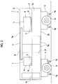
- the vehicle 1 includes a vehicle body 2, a door 5 (refer to Figs. 2 and 3 ) which is provided in the vehicle body 2, and seats 3 (refer to Figs. 3 and 4 ) which are provided inside the vehicle body 2.
- the vehicle body 2 is formed in a box shape.
- the vehicle body 2 is formed in a hollow rectangular parallelepiped shape including a passenger compartment PS in which a passenger is accommodated.
- traveling wheels 4r and traveling devices 4 are provided on both ends in a longitudinal direction of the vehicle body 2 below the base 2b which forms a vehicle floor surface 2f of the vehicle body 2.
- Each of the traveling devices 4 includes guide wheels 4g which guide an advancement direction along a track.
- the vehicle body 2 includes side walls 6 which are provided on both sides in a width direction intersecting the longitudinal direction (travel direction of the vehicle 1).
- Each of the side walls 6 includes an upper end 6a, a lower end 6b, and an expanded portion 6c which is expanded outward in the width direction at an intermediate portion in up and down directions between the upper end 6a and the lower end 6b.
- each of a portion between the upper end 6a and the expanded portion 6c and a portion between the expanded portion 6c and the lower end 6b is formed in a flat plate shape.
- a width dimension Wm between the expanded portions 6c of the side walls 6 on both sides of the vehicle body 2 in the vehicle width direction becomes a vehicle maximum width dimension of the vehicle body 2.
- the expanded portion 6c is disposed within a range of a height H1 from 600 mm to 1100 mm with respect to the vehicle floor surface 2f on the upper surface side of the base 2b, more preferably, within a range of a height H1 from 700 mm to 1000 mm, and most preferably, within a range of a height H1 from 800 mm to 900 mm.
- each of the base 2b of the vehicle body 2 and a roof 2r forming the ceiling surface of the vehicle body 2 is formed in an approximately flat plate shape.
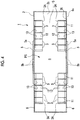
- a sectional shape in a vertical surface orthogonal to the forward and backward directions of the vehicle body 2 is formed in an approximately hexagonal shape by the base 2b, the roof 2r, and the side walls 6.
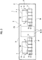
- the doors 5 are each provided on the side walls 6 on both sides in the width direction of the vehicle body 2.
- Each of the doors 5 includes a door rail 5a and side sliding doors 5b.
- the door rail 5a is provided on an upper portion of a vehicle outer side surface 6s of the side wall 6 of the vehicle body 2 facing the outside in the width direction so as to extend in the forward and backward directions.
- the side sliding doors 5b are suspended from the door rail 5a.
- the side sliding doors 5b slide in the direction along the door rail 5a on the outside in the width direction of the vehicle outer side surface 6s of the side wall 6 so as to be openable and closable.
- each of the door rails 5a is provided inward in the vehicle width direction so as not to protrude outward in the vehicle width direction from the expanded portion 6c of the side wall 6 becoming the vehicle maximum width dimension of the vehicle body 2.
- the door rail 5a may be provided not only above the expanded portion 6c but also below the expanded portion 6c. Moreover, the door rails 5a may be provided on both sides above and below the expanded portion 6c.
- window portions 7 are provided on the side walls 6 on both sides in the width direction of the vehicle body 2 at a position at which the window portions 7 do not interfere with the side sliding doors 5b of the closed door 5.
- each of the window portions 7 includes a glass 9 which is fitted into an opening portion 8 formed in the side wall 6.
- the window portion 7 is disposed above the expanded portion 6c which is the intermediate portion of the side wall 6 in the up and down directions.
- a plurality of seats 3 are provided inside the vehicle body 2.
- the plurality of seats 3 are provided to be arranged to be adjacent to each other in the forward and backward directions of the vehicle body and thus, configure a long seat 3A.
- a seat 3 may be provided inside the vehicle body 2 as a single body.
- the seats 3 are provided on the side wall 6 of the vehicle 1 so as to face the inside in the vehicle width direction.
- Each of the seats 3 includes frames 11, seat surfaces 12, and seatbacks 13.
- a plurality of frames 11 are disposed at intervals in the longitudinal direction of the vehicle body 2.
- the frames 11 are disposed on both sides in a seat width direction (the longitudinal direction of the vehicle body 2) of each seat 3.
- each frame 11 includes a seat surface support portion 11a and a rear surface support portion 11b.
- the seat surface support portion 11a extends in a vehicle width direction above the vehicle floor surface 2f of the vehicle body 2.
- the rear surface support portion 11b extends in the up and down directions along a vehicle inner side surface 6t facing the inside of the side wall 6 in the vehicle width direction. Accordingly, each frame 11 is formed in an approximately L shape as a whole.
- connection arm portion 11c is integrally formed with the lower end of the rear surface support portion 11b of each frame 11.
- the connection arm portion 11c is inclined inward in the vehicle width direction toward the lower side and is connected to one end 11p of the seat surface support portion 11a.
- the seat surface support portion 11a is inclined to gradually extend upward from the one end 11p side connected to the lower end of the connection arm portion 11c toward the other end 11q on the inside in the vehicle width direction.
- a locking claw 14 which vertically protrudes downward is formed on the lower end of the rear surface support portion 11b of each frame 11.
- a bolt insertion hole 16 into which an attachment bolt 15 is inserted is formed on the upper end of the rear surface support portion 11b.
- a locking claw 14 is locked to a locking groove 20 which is formed on the vehicle inner side surface 6t of the side wall 6.
- the locking groove 20 is formed in a recess shape which is recessed downward and extends in the longitudinal direction of the vehicle body 2.
- the attachment bolt 15 inserted into the bolt insertion hole 16 is attached to a fixed base 21 which is formed on the vehicle inner side surface 6t of the side wall 6. Accordingly, an upper end 11t of the rear surface support portion 11b of the frame 11 is fixed to the fixed base 21 in a state of abutting on the fixed base 21.
- the fixed base 21 becomes a rail which extends in the longitudinal direction of the vehicle body 2. A bolt head of the attachment bolt 15 can be inserted into the rail from the end in the longitudinal direction.
- the screw portion is fixed to the upper end 11t of the rear surface support portion 11b by a nut 15a. Accordingly, the frame 11 is fixed to the side wall 6 via the rail.
- the fixed base 21 is formed on the vehicle inner side surface 6t of the side wall 6 below the expanded portion 6c by a predetermined dimension.
- the seat surface 12 is formed to extend from the lower end of the seatback 13 toward the inside in the vehicle width direction.
- the seat surface 12 includes a seat surface base plate 17 which is disposed on the seat surface support portion 11a of the frame 11 and a seat surface cushion 18 which is provided on the seat surface base plate 17.
- the seat surface base plate 17 is formed to be continuous in the longitudinal direction of the vehicle body 2.
- the seat surface base plate 17 is provided over the seat surface support portions 11a of the plurality of frames 11 disposed at intervals in the longitudinal direction of the vehicle body 2.
- the seat surface base plate 17 is fixed to be fastened to the seat surface support portions 11a of the frames 11 by the bolts 19.
- the seat surface cushion 18 is separated for each passenger.
- the seat surface cushion 18 is formed of an elastic material such as foamed urethane.
- the seat surface cushion 18 is fixed to the seat surface base plate 17 by a hook structure, a bolt (not shown), or the like to cover the seat surface base plate 17 from above. Accordingly, the upper surface of the seat surface cushion 18 becomes a seating surface 18s on which passenger seats.
- a tip portion 18t inside the seat surface cushion 18 in the vehicle width direction is provided to protrude inward in the vehicle width direction from the other end 11q of the seat surface support portion 11a.
- a length dimension in the forward and backward directions (directions which coincide with the vehicle width direction) of the seat surface cushion 18 is approximately 500 mm.
- the seat surface cushion 18 is provided in a state of entering the lower portion of the seatback 13 by approximately 50 mm.
- the seatback 13 is separated for each passenger.
- the seatback 13 is provided so as to cover the rear surface support portion 11b of the frame 11 from the inside in the vehicle width direction.
- an upper end 13t thereof protrudes upward from the upper end 11t of the rear surface support portion 11b of the frame 11, the expanded portion 6c of the side wall 6, and the lower edge 7b of the window portion 7.
- the upper end 13t of the seatback 13 may be set to a height H2 of a range from 700 mm to 1200 mm with respect to the vehicle floor surface 2f on the upper surface side of the base 2b, more preferably, a height H2 of a range from 800 mm to 1100 mm, and most preferably, a height H2 of a range from 900 mm to 1000 mm.
- An abutment portion 13p which abuts on a portion 6p corresponding to the expanded portion 6c on the vehicle inner side surface 6t of the side wall 6 is provided at a portion of a rear surface side of the upper end 13t of the seatback 13 which faces the side wall 6 and protrudes farthest toward the side wall 6 side.
- a bracket 13a protruding toward the side wall 6 is provided at a position close to the upper end 13t of the seatback 13.
- a bracket 21a which protrudes in a direction separated from the side wall 6 is provided on the fixed base 21.
- the bracket 21a is fixed to the fixed base 21 which is the rail by a bolt and a nut.
- the bracket 13a is hooked to the bracket 21a from above, and thus, the seatback 13 is fixed to the side wall 6.
- the position at which the bracket 13a and the bracket 21a are provided becomes an approximately intermediate position of each seatback 13 in the seat width direction.
- the lower end 13b of the seatback 13 is fixed to the seat surface base plate 17 by a fastener 22.
- the seatback 13 is formed of an elastic material such as foamed urethane.
- the seatback 13 may be inclined by 15° outward in the vehicle width direction upward in a height direction of the vehicle 1. That is, a torso angle may be 15°.
- the abutment portion 13p which is the portion of the rear surface of the seatback 13 of the seat 3 which protrudes farthest toward the side wall 6 side is disposed so as to face the portion 6p on the vehicle inner side surface 6t of the side wall 6 facing the expanded portion 6c. Accordingly, it is possible to dispose the seat 3 at the position closest to the outside in the vehicle width direction. Therefore, a space S such as a passageway formed between seats 3 on both sides in the vehicle width direction can be secured to the maximum width. As a result, it is possible to effectively use a space inside the vehicle body 2.
- the upper end 11t of the frame 11 is fixed at the position below the portion 6p of the vehicle inner side surface 6t of the side wall 6 facing the expanded portion 6c. Accordingly, compared to a case where the frame 11 is fixed to the expanded portion 6c, the frame 11 can be more easily and reliably fixed.
- the upper end 13t of the seatback 13 protrudes upward from the lower edge 7b of the window portion 7. According to this configuration, the height of the seatback 13 is largely secured while the seat 3 is mounted at the position closest to the outside in the vehicle width direction, and thus, it is possible to improve comfort at the time of seating.
- the lower edge 7b of the window portion 7 is positioned below the upper end 13t of the seatback 13. Accordingly, it is possible to increase the dimension in the height direction of the window portion 7 and it is possible to increase the feeling of opening in the space inside the vehicle body 2. Moreover, the dimension of the window portion 7 can be increased, which leads to an improvement in the design of the exterior.
- the door rail 5a extending in the travel direction is provided on the vehicle outer side surface 6s facing the outside in the width direction, and the side sliding doors 5b sliding along the door rail 5a are provided on the outside in the width direction from the vehicle outer side surface 6s of the side wall 6.
- the door rail 5a is disposed above the expanded portion 6c and is provided on the inside in the width direction from the expanded portion 6c.
- the door rail 5a and the side sliding doors 5b are provided on the outside of the side wall 6 in the width direction, in general, according to the regulation of vehicle limits, it is necessary to install the side wall 6 of the vehicle body 2 on the inside in the vehicle width direction. As a result, the dimension in the internal space of the vehicle body 2 in the width direction is decreased. Meanwhile, the expanded portion 6c is disposed below the door rail 5a, and thus, the maximum width dimension of the internal space of the vehicle body 2 can be secured.
- the upper end 6a and the expanded portion 6c are linearly connected to each other and the lower end 6b and the expanded portion 6c are linearly connected to each other, and thus, the sectional shape of the vehicle body 2 is hexagonal.
- the seat 3 is disposed to be close to the outside in the width direction, and thus, the outline of the vehicle body 2 is formed to be characteristic while the space S such as a passageway formed between the seats 3 on both sides in the vehicle width direction is secured to the maximum width.
- the present invention is not limited to the above-described embodiment. That is, the specific shapes, configurations, or the like described in the embodiment are only examples and can be appropriately changed.
- the portion between the upper end 6a and the expanded portion 6c and the portion between the expanded portion 6c and the lower end 6b are formed in a flat plate shape.
- the present invention is not limited to this.
- the side wall 6 may be formed in a curved sectional shape as long as the expanded portion 6c in the side wall 6 protrudes farthest toward the outside in the width direction.
- the sectional shape of the vehicle body 2 is not limited to a hexagonal shape.
- the sectional shape may be a polygonal shape such as an octagonal shape.
- the base 2b of the vehicle body 2 and the roof 2r forming the ceiling surface of the vehicle body 2 are approximately flat plate shapes.
- the present invention is not limited to this, and for example, the base 2b and the roof 2r may be a curved plate shape or a bent plate shape.
- the door 5 may be provided on the vehicle inner side surface 6t facing the inside of the side wall 6 in the width direction.
- the space such as a passageway is secured to the maximum width, and thus, it is possible to effectively use the space inside the vehicle.
Landscapes
- Engineering & Computer Science (AREA)
- Mechanical Engineering (AREA)
- Transportation (AREA)
- Aviation & Aerospace Engineering (AREA)
- Health & Medical Sciences (AREA)
- Child & Adolescent Psychology (AREA)
- General Health & Medical Sciences (AREA)
- Life Sciences & Earth Sciences (AREA)
- Wood Science & Technology (AREA)
- Chemical & Material Sciences (AREA)
- Combustion & Propulsion (AREA)
- Seats For Vehicles (AREA)
Applications Claiming Priority (2)
| Application Number | Priority Date | Filing Date | Title |
|---|---|---|---|
| JP2015148822A JP6528277B2 (ja) | 2015-07-28 | 2015-07-28 | 車両 |
| PCT/JP2016/071014 WO2017018251A1 (ja) | 2015-07-28 | 2016-07-15 | 車両 |
Publications (3)
| Publication Number | Publication Date |
|---|---|
| EP3287336A1 EP3287336A1 (en) | 2018-02-28 |
| EP3287336A4 EP3287336A4 (en) | 2018-04-25 |
| EP3287336B1 true EP3287336B1 (en) | 2019-09-11 |
Family
ID=57884511
Family Applications (1)
| Application Number | Title | Priority Date | Filing Date |
|---|---|---|---|
| EP16830356.8A Active EP3287336B1 (en) | 2015-07-28 | 2016-07-15 | Vehicle |
Country Status (6)
| Country | Link |
|---|---|
| US (1) | US10696188B2 (ja) |
| EP (1) | EP3287336B1 (ja) |
| JP (1) | JP6528277B2 (ja) |
| KR (1) | KR102005171B1 (ja) |
| CN (1) | CN107709129B (ja) |
| WO (1) | WO2017018251A1 (ja) |
Families Citing this family (4)
| Publication number | Priority date | Publication date | Assignee | Title |
|---|---|---|---|---|
| US10239425B2 (en) * | 2017-06-16 | 2019-03-26 | GM Global Technology Operations LLC | Movable partition system for a vehicle with stowable jumpseat |
| IT201800004098A1 (it) * | 2018-03-29 | 2019-09-29 | Iveco France Sas | Schienale per veicolo |
| CN109572730B (zh) * | 2019-01-29 | 2024-04-19 | 中车长春轨道客车股份有限公司 | 一种轨道客车座椅侧墙安装结构 |
| CN113320558B (zh) * | 2021-06-10 | 2023-01-24 | 中车唐山机车车辆有限公司 | 车厢及轨道车辆 |
Family Cites Families (23)
| Publication number | Priority date | Publication date | Assignee | Title |
|---|---|---|---|---|
| GB191505437A (en) | 1915-04-10 | 1915-09-02 | William Edward Constable | Improvements in and relating to Sliding Doors for Railway Cars and other Structures. |
| US1768060A (en) | 1925-08-06 | 1930-06-24 | Camel Co | Door |
| US4061089A (en) * | 1975-09-02 | 1977-12-06 | Elbert Morgan Sawyer | Personal rapid transit system |
| FR2736751B1 (fr) | 1995-07-12 | 1997-08-14 | Gec Alsthom T & D Sa | Dispositif d'actionnement d'un appareil electrique en particulier d'un sectionneur ou d'un sectionneur de mise a la terre haute tension |
| JP3431772B2 (ja) * | 1996-08-27 | 2003-07-28 | 天龍工業株式会社 | 乗物用座席の配列切替装置 |
| AT410819B (de) | 2000-08-31 | 2003-08-25 | Siemens Sgp Verkehrstech Gmbh | Türbefestigung |
| JP2002205641A (ja) | 2001-01-11 | 2002-07-23 | Nippon Sharyo Seizo Kaisha Ltd | 鉄道車両の腰掛け構造 |
| FR2822765B1 (fr) | 2001-03-29 | 2003-06-27 | Regie Autonome Transports | Ensemble de siege pour vehicule de transport en commun |
| US6685254B2 (en) * | 2002-05-13 | 2004-02-03 | J. Bruce Emmons | Low floor mass transit vehicle |
| WO2004087479A2 (en) | 2003-03-25 | 2004-10-14 | Dte Rail Services, Inc. | Trolley system for a railway boxcar door |
| JP5020548B2 (ja) | 2006-06-06 | 2012-09-05 | シロキ工業株式会社 | シートの座部構造 |
| JP2010221933A (ja) * | 2009-03-25 | 2010-10-07 | Sumie Kogyo Kk | シート構造 |
| US8579350B2 (en) * | 2009-12-14 | 2013-11-12 | Kustom Seating Unlimited, Ltd. | Modular transit system |
| JP2011213226A (ja) * | 2010-03-31 | 2011-10-27 | Hitachi Ltd | 軌条車両 |
| CN103635371B (zh) * | 2011-02-17 | 2016-09-21 | 东日本旅客铁道株式会社 | 铁道车辆 |
| ITTO20110579A1 (it) | 2011-06-30 | 2012-12-31 | Maio Francesco Paolo Di | Gruppo porte per veicoli su rotaia, in particolare per treni metropolitani |
| JP5871586B2 (ja) * | 2011-11-24 | 2016-03-01 | 三菱重工業株式会社 | 接合体及び接合体からなる車両、接合体の製造方法 |
| CN202827227U (zh) | 2012-08-30 | 2013-03-27 | 中国北车集团大连机车车辆有限公司 | 不锈钢车辆座椅骨架结构 |
| JP6062692B2 (ja) * | 2012-09-13 | 2017-01-18 | 公益財団法人鉄道総合技術研究所 | 鉄道車両用車体 |
| JP6211341B2 (ja) * | 2013-08-08 | 2017-10-11 | 近畿車輌株式会社 | 鉄道車両 |
| CN203460871U (zh) | 2013-08-23 | 2014-03-05 | 长春轨道客车股份有限公司 | 设有九人位座椅的a型车辆内装系统 |
| CN104527686B (zh) * | 2014-11-26 | 2017-01-04 | 中车南京浦镇车辆有限公司 | 轨道车辆纵向座椅 |
| CN204296737U (zh) | 2014-12-04 | 2015-04-29 | 长春轨道客车股份有限公司 | 一种翻转座椅结构 |
-
2015
- 2015-07-28 JP JP2015148822A patent/JP6528277B2/ja active Active
-
2016
- 2016-07-15 KR KR1020177035760A patent/KR102005171B1/ko active IP Right Grant
- 2016-07-15 CN CN201680035175.3A patent/CN107709129B/zh active Active
- 2016-07-15 WO PCT/JP2016/071014 patent/WO2017018251A1/ja active Application Filing
- 2016-07-15 EP EP16830356.8A patent/EP3287336B1/en active Active
- 2016-07-15 US US15/574,680 patent/US10696188B2/en active Active
Non-Patent Citations (1)
| Title |
|---|
| None * |
Also Published As
| Publication number | Publication date |
|---|---|
| JP6528277B2 (ja) | 2019-06-12 |
| EP3287336A4 (en) | 2018-04-25 |
| EP3287336A1 (en) | 2018-02-28 |
| WO2017018251A1 (ja) | 2017-02-02 |
| CN107709129A (zh) | 2018-02-16 |
| KR20180008580A (ko) | 2018-01-24 |
| KR102005171B1 (ko) | 2019-07-29 |
| CN107709129B (zh) | 2020-01-14 |
| US20180126874A1 (en) | 2018-05-10 |
| US10696188B2 (en) | 2020-06-30 |
| JP2017024692A (ja) | 2017-02-02 |
Similar Documents
| Publication | Publication Date | Title |
|---|---|---|
| EP3287336B1 (en) | Vehicle | |
| US9751431B2 (en) | Seat track assembly having load absorption features | |
| CN102123907B (zh) | 飞机客舱的预装配和集成 | |
| US7988231B2 (en) | Low maintenance configuration for sliding seats | |
| US8708387B2 (en) | Console box | |
| US8827350B1 (en) | Side impact upper leg pusher | |
| US20180334058A1 (en) | Vehicle seat fastening structure and vehicle seat fastener | |
| EP3421318A1 (en) | Railway vehicle | |
| JP6196536B2 (ja) | 鉄道車両の内装品取付構造及び内装品取付方法 | |
| EP3636508B1 (en) | Railway train and compartment thereof | |
| CN104512482A (zh) | 车身构造 | |
| US9694718B2 (en) | Vehicle seat | |
| US9873398B2 (en) | Vehicle interior structure | |
| US11180053B2 (en) | Longitudinal adjuster and vehicle seat | |
| JP5414107B2 (ja) | シートクッションの取り付け構造 | |
| US10899370B2 (en) | Paneling modules for vehicles | |
| JP2008105507A (ja) | 車両の下部車体構造 | |
| KR102244441B1 (ko) | 자동차 운전석 보호격벽 | |
| JP7182081B2 (ja) | 車両のキャブ構造 | |
| US20240262429A1 (en) | Vehicle lower portion structure | |
| KR200249828Y1 (ko) | 전동차승객용 머리 받침대 | |
| EP3293040B1 (en) | Method of changing a seat configuration of a vehicle body of a rail vehicle and associated modular arrangement | |
| CN113978323A (zh) | 用于公共交通车辆的座椅附接系统 | |
| JP2008126834A (ja) | 車両の後部車体構造 | |
| JP2008308046A (ja) | 車両内部の荷物棚 |
Legal Events
| Date | Code | Title | Description |
|---|---|---|---|
| STAA | Information on the status of an ep patent application or granted ep patent |
Free format text: STATUS: THE INTERNATIONAL PUBLICATION HAS BEEN MADE |
|
| PUAI | Public reference made under article 153(3) epc to a published international application that has entered the european phase |
Free format text: ORIGINAL CODE: 0009012 |
|
| STAA | Information on the status of an ep patent application or granted ep patent |
Free format text: STATUS: REQUEST FOR EXAMINATION WAS MADE |
|
| 17P | Request for examination filed |
Effective date: 20171115 |
|
| AK | Designated contracting states |
Kind code of ref document: A1 Designated state(s): AL AT BE BG CH CY CZ DE DK EE ES FI FR GB GR HR HU IE IS IT LI LT LU LV MC MK MT NL NO PL PT RO RS SE SI SK SM TR |
|
| AX | Request for extension of the european patent |
Extension state: BA ME |
|
| RIC1 | Information provided on ipc code assigned before grant |
Ipc: B60N 2/015 20060101ALI20180307BHEP Ipc: B60N 2/30 20060101ALI20180307BHEP Ipc: B61D 17/08 20060101ALI20180307BHEP Ipc: B61D 1/04 20060101AFI20180307BHEP Ipc: B60N 2/005 20060101ALI20180307BHEP Ipc: B61D 33/00 20060101ALI20180307BHEP Ipc: B60N 2/24 20060101ALI20180307BHEP Ipc: B60N 2/28 20060101ALI20180307BHEP Ipc: B61D 19/00 20060101ALI20180307BHEP |
|
| A4 | Supplementary search report drawn up and despatched |
Effective date: 20180326 |
|
| RAP1 | Party data changed (applicant data changed or rights of an application transferred) |
Owner name: MITSUBISHI HEAVY INDUSTRIES ENGINEERING, LTD. |
|
| DAV | Request for validation of the european patent (deleted) | ||
| DAX | Request for extension of the european patent (deleted) | ||
| RIC1 | Information provided on ipc code assigned before grant |
Ipc: B61D 1/04 20060101AFI20190124BHEP Ipc: B60N 2/005 20060101ALI20190124BHEP Ipc: B61D 17/08 20060101ALI20190124BHEP Ipc: B61D 33/00 20060101ALI20190124BHEP Ipc: B60N 2/28 20060101ALI20190124BHEP Ipc: B60N 2/015 20060101ALI20190124BHEP Ipc: B61D 19/00 20060101ALI20190124BHEP Ipc: B60N 2/30 20060101ALI20190124BHEP Ipc: B60N 2/24 20060101ALI20190124BHEP |
|
| GRAP | Despatch of communication of intention to grant a patent |
Free format text: ORIGINAL CODE: EPIDOSNIGR1 |
|
| STAA | Information on the status of an ep patent application or granted ep patent |
Free format text: STATUS: GRANT OF PATENT IS INTENDED |
|
| INTG | Intention to grant announced |
Effective date: 20190306 |
|
| GRAS | Grant fee paid |
Free format text: ORIGINAL CODE: EPIDOSNIGR3 |
|
| GRAA | (expected) grant |
Free format text: ORIGINAL CODE: 0009210 |
|
| STAA | Information on the status of an ep patent application or granted ep patent |
Free format text: STATUS: THE PATENT HAS BEEN GRANTED |
|
| AK | Designated contracting states |
Kind code of ref document: B1 Designated state(s): AL AT BE BG CH CY CZ DE DK EE ES FI FR GB GR HR HU IE IS IT LI LT LU LV MC MK MT NL NO PL PT RO RS SE SI SK SM TR |
|
| REG | Reference to a national code |
Ref country code: GB Ref legal event code: FG4D |
|
| REG | Reference to a national code |
Ref country code: CH Ref legal event code: EP |
|
| REG | Reference to a national code |
Ref country code: AT Ref legal event code: REF Ref document number: 1178059 Country of ref document: AT Kind code of ref document: T Effective date: 20190915 |
|
| REG | Reference to a national code |
Ref country code: DE Ref legal event code: R096 Ref document number: 602016020613 Country of ref document: DE Ref country code: IE Ref legal event code: FG4D |
|
| REG | Reference to a national code |
Ref country code: NL Ref legal event code: MP Effective date: 20190911 |
|
| REG | Reference to a national code |
Ref country code: LT Ref legal event code: MG4D |
|
| PG25 | Lapsed in a contracting state [announced via postgrant information from national office to epo] |
Ref country code: NO Free format text: LAPSE BECAUSE OF FAILURE TO SUBMIT A TRANSLATION OF THE DESCRIPTION OR TO PAY THE FEE WITHIN THE PRESCRIBED TIME-LIMIT Effective date: 20191211 Ref country code: LT Free format text: LAPSE BECAUSE OF FAILURE TO SUBMIT A TRANSLATION OF THE DESCRIPTION OR TO PAY THE FEE WITHIN THE PRESCRIBED TIME-LIMIT Effective date: 20190911 Ref country code: BG Free format text: LAPSE BECAUSE OF FAILURE TO SUBMIT A TRANSLATION OF THE DESCRIPTION OR TO PAY THE FEE WITHIN THE PRESCRIBED TIME-LIMIT Effective date: 20191211 Ref country code: FI Free format text: LAPSE BECAUSE OF FAILURE TO SUBMIT A TRANSLATION OF THE DESCRIPTION OR TO PAY THE FEE WITHIN THE PRESCRIBED TIME-LIMIT Effective date: 20190911 Ref country code: HR Free format text: LAPSE BECAUSE OF FAILURE TO SUBMIT A TRANSLATION OF THE DESCRIPTION OR TO PAY THE FEE WITHIN THE PRESCRIBED TIME-LIMIT Effective date: 20190911 Ref country code: SE Free format text: LAPSE BECAUSE OF FAILURE TO SUBMIT A TRANSLATION OF THE DESCRIPTION OR TO PAY THE FEE WITHIN THE PRESCRIBED TIME-LIMIT Effective date: 20190911 |
|
| PG25 | Lapsed in a contracting state [announced via postgrant information from national office to epo] |
Ref country code: ES Free format text: LAPSE BECAUSE OF FAILURE TO SUBMIT A TRANSLATION OF THE DESCRIPTION OR TO PAY THE FEE WITHIN THE PRESCRIBED TIME-LIMIT Effective date: 20190911 Ref country code: AL Free format text: LAPSE BECAUSE OF FAILURE TO SUBMIT A TRANSLATION OF THE DESCRIPTION OR TO PAY THE FEE WITHIN THE PRESCRIBED TIME-LIMIT Effective date: 20190911 Ref country code: GR Free format text: LAPSE BECAUSE OF FAILURE TO SUBMIT A TRANSLATION OF THE DESCRIPTION OR TO PAY THE FEE WITHIN THE PRESCRIBED TIME-LIMIT Effective date: 20191212 Ref country code: RS Free format text: LAPSE BECAUSE OF FAILURE TO SUBMIT A TRANSLATION OF THE DESCRIPTION OR TO PAY THE FEE WITHIN THE PRESCRIBED TIME-LIMIT Effective date: 20190911 Ref country code: LV Free format text: LAPSE BECAUSE OF FAILURE TO SUBMIT A TRANSLATION OF THE DESCRIPTION OR TO PAY THE FEE WITHIN THE PRESCRIBED TIME-LIMIT Effective date: 20190911 |
|
| PG25 | Lapsed in a contracting state [announced via postgrant information from national office to epo] |
Ref country code: PT Free format text: LAPSE BECAUSE OF FAILURE TO SUBMIT A TRANSLATION OF THE DESCRIPTION OR TO PAY THE FEE WITHIN THE PRESCRIBED TIME-LIMIT Effective date: 20200113 Ref country code: IT Free format text: LAPSE BECAUSE OF FAILURE TO SUBMIT A TRANSLATION OF THE DESCRIPTION OR TO PAY THE FEE WITHIN THE PRESCRIBED TIME-LIMIT Effective date: 20190911 Ref country code: EE Free format text: LAPSE BECAUSE OF FAILURE TO SUBMIT A TRANSLATION OF THE DESCRIPTION OR TO PAY THE FEE WITHIN THE PRESCRIBED TIME-LIMIT Effective date: 20190911 Ref country code: PL Free format text: LAPSE BECAUSE OF FAILURE TO SUBMIT A TRANSLATION OF THE DESCRIPTION OR TO PAY THE FEE WITHIN THE PRESCRIBED TIME-LIMIT Effective date: 20190911 Ref country code: RO Free format text: LAPSE BECAUSE OF FAILURE TO SUBMIT A TRANSLATION OF THE DESCRIPTION OR TO PAY THE FEE WITHIN THE PRESCRIBED TIME-LIMIT Effective date: 20190911 Ref country code: NL Free format text: LAPSE BECAUSE OF FAILURE TO SUBMIT A TRANSLATION OF THE DESCRIPTION OR TO PAY THE FEE WITHIN THE PRESCRIBED TIME-LIMIT Effective date: 20190911 |
|
| PG25 | Lapsed in a contracting state [announced via postgrant information from national office to epo] |
Ref country code: IS Free format text: LAPSE BECAUSE OF FAILURE TO SUBMIT A TRANSLATION OF THE DESCRIPTION OR TO PAY THE FEE WITHIN THE PRESCRIBED TIME-LIMIT Effective date: 20200224 Ref country code: SK Free format text: LAPSE BECAUSE OF FAILURE TO SUBMIT A TRANSLATION OF THE DESCRIPTION OR TO PAY THE FEE WITHIN THE PRESCRIBED TIME-LIMIT Effective date: 20190911 Ref country code: CZ Free format text: LAPSE BECAUSE OF FAILURE TO SUBMIT A TRANSLATION OF THE DESCRIPTION OR TO PAY THE FEE WITHIN THE PRESCRIBED TIME-LIMIT Effective date: 20190911 Ref country code: SM Free format text: LAPSE BECAUSE OF FAILURE TO SUBMIT A TRANSLATION OF THE DESCRIPTION OR TO PAY THE FEE WITHIN THE PRESCRIBED TIME-LIMIT Effective date: 20190911 |
|
| REG | Reference to a national code |
Ref country code: DE Ref legal event code: R097 Ref document number: 602016020613 Country of ref document: DE |
|
| PLBE | No opposition filed within time limit |
Free format text: ORIGINAL CODE: 0009261 |
|
| STAA | Information on the status of an ep patent application or granted ep patent |
Free format text: STATUS: NO OPPOSITION FILED WITHIN TIME LIMIT |
|
| PG2D | Information on lapse in contracting state deleted |
Ref country code: IS |
|
| PG25 | Lapsed in a contracting state [announced via postgrant information from national office to epo] |
Ref country code: DK Free format text: LAPSE BECAUSE OF FAILURE TO SUBMIT A TRANSLATION OF THE DESCRIPTION OR TO PAY THE FEE WITHIN THE PRESCRIBED TIME-LIMIT Effective date: 20190911 Ref country code: IS Free format text: LAPSE BECAUSE OF FAILURE TO SUBMIT A TRANSLATION OF THE DESCRIPTION OR TO PAY THE FEE WITHIN THE PRESCRIBED TIME-LIMIT Effective date: 20200112 |
|
| 26N | No opposition filed |
Effective date: 20200615 |
|
| PG25 | Lapsed in a contracting state [announced via postgrant information from national office to epo] |
Ref country code: SI Free format text: LAPSE BECAUSE OF FAILURE TO SUBMIT A TRANSLATION OF THE DESCRIPTION OR TO PAY THE FEE WITHIN THE PRESCRIBED TIME-LIMIT Effective date: 20190911 |
|
| REG | Reference to a national code |
Ref country code: DE Ref legal event code: R119 Ref document number: 602016020613 Country of ref document: DE |
|
| PG25 | Lapsed in a contracting state [announced via postgrant information from national office to epo] |
Ref country code: MC Free format text: LAPSE BECAUSE OF FAILURE TO SUBMIT A TRANSLATION OF THE DESCRIPTION OR TO PAY THE FEE WITHIN THE PRESCRIBED TIME-LIMIT Effective date: 20190911 |
|
| REG | Reference to a national code |
Ref country code: CH Ref legal event code: PL |
|
| GBPC | Gb: european patent ceased through non-payment of renewal fee |
Effective date: 20200715 |
|
| REG | Reference to a national code |
Ref country code: BE Ref legal event code: MM Effective date: 20200731 |
|
| PG25 | Lapsed in a contracting state [announced via postgrant information from national office to epo] |
Ref country code: CH Free format text: LAPSE BECAUSE OF NON-PAYMENT OF DUE FEES Effective date: 20200731 Ref country code: LI Free format text: LAPSE BECAUSE OF NON-PAYMENT OF DUE FEES Effective date: 20200731 Ref country code: LU Free format text: LAPSE BECAUSE OF NON-PAYMENT OF DUE FEES Effective date: 20200715 Ref country code: GB Free format text: LAPSE BECAUSE OF NON-PAYMENT OF DUE FEES Effective date: 20200715 Ref country code: FR Free format text: LAPSE BECAUSE OF NON-PAYMENT OF DUE FEES Effective date: 20200731 |
|
| PG25 | Lapsed in a contracting state [announced via postgrant information from national office to epo] |
Ref country code: BE Free format text: LAPSE BECAUSE OF NON-PAYMENT OF DUE FEES Effective date: 20200731 Ref country code: DE Free format text: LAPSE BECAUSE OF NON-PAYMENT OF DUE FEES Effective date: 20210202 |
|
| PG25 | Lapsed in a contracting state [announced via postgrant information from national office to epo] |
Ref country code: IE Free format text: LAPSE BECAUSE OF NON-PAYMENT OF DUE FEES Effective date: 20200715 |
|
| REG | Reference to a national code |
Ref country code: AT Ref legal event code: UEP Ref document number: 1178059 Country of ref document: AT Kind code of ref document: T Effective date: 20190911 |
|
| PG25 | Lapsed in a contracting state [announced via postgrant information from national office to epo] |
Ref country code: TR Free format text: LAPSE BECAUSE OF FAILURE TO SUBMIT A TRANSLATION OF THE DESCRIPTION OR TO PAY THE FEE WITHIN THE PRESCRIBED TIME-LIMIT Effective date: 20190911 Ref country code: MT Free format text: LAPSE BECAUSE OF FAILURE TO SUBMIT A TRANSLATION OF THE DESCRIPTION OR TO PAY THE FEE WITHIN THE PRESCRIBED TIME-LIMIT Effective date: 20190911 Ref country code: CY Free format text: LAPSE BECAUSE OF FAILURE TO SUBMIT A TRANSLATION OF THE DESCRIPTION OR TO PAY THE FEE WITHIN THE PRESCRIBED TIME-LIMIT Effective date: 20190911 |
|
| PG25 | Lapsed in a contracting state [announced via postgrant information from national office to epo] |
Ref country code: MK Free format text: LAPSE BECAUSE OF FAILURE TO SUBMIT A TRANSLATION OF THE DESCRIPTION OR TO PAY THE FEE WITHIN THE PRESCRIBED TIME-LIMIT Effective date: 20190911 |
|
| PGFP | Annual fee paid to national office [announced via postgrant information from national office to epo] |
Ref country code: AT Payment date: 20220627 Year of fee payment: 7 |
|
| REG | Reference to a national code |
Ref country code: AT Ref legal event code: MM01 Ref document number: 1178059 Country of ref document: AT Kind code of ref document: T Effective date: 20230715 |
|
| PG25 | Lapsed in a contracting state [announced via postgrant information from national office to epo] |
Ref country code: AT Free format text: LAPSE BECAUSE OF NON-PAYMENT OF DUE FEES Effective date: 20230715 |
|
| PG25 | Lapsed in a contracting state [announced via postgrant information from national office to epo] |
Ref country code: AT Free format text: LAPSE BECAUSE OF NON-PAYMENT OF DUE FEES Effective date: 20230715 |