EP3260101B1 - Bewegungsbasiertes antriebsunterstützungssystem für rollstühle - Google Patents
Bewegungsbasiertes antriebsunterstützungssystem für rollstühle Download PDFInfo
- Publication number
- EP3260101B1 EP3260101B1 EP17162833.2A EP17162833A EP3260101B1 EP 3260101 B1 EP3260101 B1 EP 3260101B1 EP 17162833 A EP17162833 A EP 17162833A EP 3260101 B1 EP3260101 B1 EP 3260101B1
- Authority
- EP
- European Patent Office
- Prior art keywords
- power assist
- assist system
- drive
- motion
- wheelchair
- Prior art date
- Legal status (The legal status is an assumption and is not a legal conclusion. Google has not performed a legal analysis and makes no representation as to the accuracy of the status listed.)
- Active
Links
- 230000033001 locomotion Effects 0.000 title claims description 33
- 230000001133 acceleration Effects 0.000 claims description 18
- 230000004913 activation Effects 0.000 claims description 13
- 238000005259 measurement Methods 0.000 claims description 12
- 208000027418 Wounds and injury Diseases 0.000 description 4
- 238000013459 approach Methods 0.000 description 4
- 230000008901 benefit Effects 0.000 description 4
- 230000006378 damage Effects 0.000 description 4
- 208000014674 injury Diseases 0.000 description 4
- 210000001364 upper extremity Anatomy 0.000 description 4
- 238000013461 design Methods 0.000 description 3
- 238000000034 method Methods 0.000 description 2
- 230000004044 response Effects 0.000 description 2
- 230000005355 Hall effect Effects 0.000 description 1
- 235000014676 Phragmites communis Nutrition 0.000 description 1
- 206010039227 Rotator cuff syndrome Diseases 0.000 description 1
- 230000003213 activating effect Effects 0.000 description 1
- 230000006978 adaptation Effects 0.000 description 1
- 230000005540 biological transmission Effects 0.000 description 1
- 208000003295 carpal tunnel syndrome Diseases 0.000 description 1
- 230000009194 climbing Effects 0.000 description 1
- 230000003247 decreasing effect Effects 0.000 description 1
- 230000001419 dependent effect Effects 0.000 description 1
- 238000011161 development Methods 0.000 description 1
- 230000000694 effects Effects 0.000 description 1
- 238000005516 engineering process Methods 0.000 description 1
- 230000007613 environmental effect Effects 0.000 description 1
- 230000005284 excitation Effects 0.000 description 1
- 231100001261 hazardous Toxicity 0.000 description 1
- 238000012986 modification Methods 0.000 description 1
- 230000004048 modification Effects 0.000 description 1
- 210000003205 muscle Anatomy 0.000 description 1
- 230000003287 optical effect Effects 0.000 description 1
- 230000008092 positive effect Effects 0.000 description 1
- 230000008569 process Effects 0.000 description 1
- 238000012545 processing Methods 0.000 description 1
- 238000005096 rolling process Methods 0.000 description 1
- 210000000707 wrist Anatomy 0.000 description 1
Images


Classifications
-
- A—HUMAN NECESSITIES
- A61—MEDICAL OR VETERINARY SCIENCE; HYGIENE
- A61G—TRANSPORT, PERSONAL CONVEYANCES, OR ACCOMMODATION SPECIALLY ADAPTED FOR PATIENTS OR DISABLED PERSONS; OPERATING TABLES OR CHAIRS; CHAIRS FOR DENTISTRY; FUNERAL DEVICES
- A61G5/00—Chairs or personal conveyances specially adapted for patients or disabled persons, e.g. wheelchairs
- A61G5/04—Chairs or personal conveyances specially adapted for patients or disabled persons, e.g. wheelchairs motor-driven
- A61G5/041—Chairs or personal conveyances specially adapted for patients or disabled persons, e.g. wheelchairs motor-driven having a specific drive-type
- A61G5/045—Rear wheel drive
-
- A—HUMAN NECESSITIES
- A61—MEDICAL OR VETERINARY SCIENCE; HYGIENE
- A61G—TRANSPORT, PERSONAL CONVEYANCES, OR ACCOMMODATION SPECIALLY ADAPTED FOR PATIENTS OR DISABLED PERSONS; OPERATING TABLES OR CHAIRS; CHAIRS FOR DENTISTRY; FUNERAL DEVICES
- A61G5/00—Chairs or personal conveyances specially adapted for patients or disabled persons, e.g. wheelchairs
- A61G5/04—Chairs or personal conveyances specially adapted for patients or disabled persons, e.g. wheelchairs motor-driven
- A61G5/047—Chairs or personal conveyances specially adapted for patients or disabled persons, e.g. wheelchairs motor-driven by a modular detachable drive system
-
- A—HUMAN NECESSITIES
- A61—MEDICAL OR VETERINARY SCIENCE; HYGIENE
- A61G—TRANSPORT, PERSONAL CONVEYANCES, OR ACCOMMODATION SPECIALLY ADAPTED FOR PATIENTS OR DISABLED PERSONS; OPERATING TABLES OR CHAIRS; CHAIRS FOR DENTISTRY; FUNERAL DEVICES
- A61G5/00—Chairs or personal conveyances specially adapted for patients or disabled persons, e.g. wheelchairs
- A61G5/04—Chairs or personal conveyances specially adapted for patients or disabled persons, e.g. wheelchairs motor-driven
- A61G5/048—Power-assistance activated by pushing on hand rim or on handlebar
-
- A—HUMAN NECESSITIES
- A61—MEDICAL OR VETERINARY SCIENCE; HYGIENE
- A61G—TRANSPORT, PERSONAL CONVEYANCES, OR ACCOMMODATION SPECIALLY ADAPTED FOR PATIENTS OR DISABLED PERSONS; OPERATING TABLES OR CHAIRS; CHAIRS FOR DENTISTRY; FUNERAL DEVICES
- A61G2203/00—General characteristics of devices
- A61G2203/10—General characteristics of devices characterised by specific control means, e.g. for adjustment or steering
- A61G2203/12—Remote controls
-
- A—HUMAN NECESSITIES
- A61—MEDICAL OR VETERINARY SCIENCE; HYGIENE
- A61G—TRANSPORT, PERSONAL CONVEYANCES, OR ACCOMMODATION SPECIALLY ADAPTED FOR PATIENTS OR DISABLED PERSONS; OPERATING TABLES OR CHAIRS; CHAIRS FOR DENTISTRY; FUNERAL DEVICES
- A61G2203/00—General characteristics of devices
- A61G2203/30—General characteristics of devices characterised by sensor means
- A61G2203/36—General characteristics of devices characterised by sensor means for motion
Definitions
- This invention relates to a power assist system for manual wheelchairs, specifically a system that employs motion-based sensing for recognition of user propulsion and braking.
- Wheelchair propulsion is one activity that has been associated with the development of these upper extremity injuries. It is recommended that users reduce how hard they push on the handrim and to do it less frequently in order to reduce the stresses of propulsion on the upper body.
- Prior art presents power attachment units that have been used to mount to manual wheelchairs to assist in propulsion.
- the typical power add-on comparable to that disclosed in US Patent No. 4,759,418 , employs a linkage system that mounts to the wheelchair frame and trails in between the two rear wheels.
- An electric motor powers a drive wheel that is controlled by a push button located within reach of the user.
- This type of design not common to all power attachments, also employs a steering bar that attaches to the front casters in order to guide the wheelchair when being driven by the power add-on.
- These electric drive attachments are known to be successful in helping to reduce the physical effort needed for propulsion.
- a drawback is that these types of systems completely eliminate the need for pushing because the user drives the wheelchair, rather than maneuvers it through pushes. In this situation, the user does not benefit from the physical exercise of manual propulsion or the psychological benefits of not being dependent on the device for transportation.
- Push activated power assist wheels combine the benefits of manual push operation by the user and power assistance to reduce the demand on the user's upper extremities during propulsion.
- Push activated power assist wheels similar to those disclosed in US Patent No. 5,818,189 , are battery powered wheels that employ either force and torque sensors, or both, to measure the force applied to the handrims from the user and amplify that force through the use of motors embedded in the wheels to drive the wheelchair forward or backward.
- This technology has been shown to have a number of positive effects on wheelchair users, including reduced energy expenditure, reduced push cadence, reduced muscle activation, decreased range of motion, easier hill climbing, increased propulsion speed and reduced pain during propulsion for those users already experiencing pain.
- a motion based power assist system for manual wheelchairs.
- This power assist system uses the motion, including the angular and linear velocities and accelerations, of the power assist system in order to sense when a push is being performed on the handrims.
- the system uses different kinematic sensors, not force or torque sensors like the prior art, in order to measure when the wheelchair is accelerating past a certain minimal threshold, and recognizes that this is the result of the user performing a push.
- the system then provides an assistive force-pulse that is related to the experienced acceleration and velocity from propulsion.
- the system By using the kinematics of the power assist system, the system will be able to recognize different situations and adjust its contribution to the user's propulsion to compensate.
- the present invention can recognize situations when the user is trying to stop, slow down, or is beginning to tip, and in response cut off all driving assistance.
- the use of the power assist system motion and kinematics as the input to the push activation control is novel.
- Prior art devices tend to add significant weight to the wheelchair, making it difficult to get the wheelchair into and out of a car for even the strongest user. Battery life is also an issue because the power assist wheels are simply too heavy to push around without the power assist.
- the aforementioned motion-based push activation is employed on a single drive wheel attachment that mounts to the axle of a wheelchair midway between the rear wheels. Attachment mounts are clamped to the axle and attach to the drive wheel attachment, allowing for quick connecting and releasing of the system for easy transport.
- a separate example employs the motion-based push activation on electric hub motors that are embedded in the rear drive wheels of a wheelchair.
- the handrims on the rear drive wheels can be directly mounted to the wheel rim, as on traditional non-power assist wheelchair wheels.
- Another example employs the said motion-based push activation on wheelchair mounted motors that drive the rear wheels of the wheelchair.
- This embodiment uses the same motion-based means to activate frame mounted motors, instead of the aforementioned wheel mounted motors, that in turn power the driven rear wheels for an assistive force to the wheelchair and user.
- the present invention comprises a power assist system used on a manual wheelchair.
- Motion-based instrumentation measures the kinematics of the power assist system.
- the kinematics measured include, but are not limited to, linear velocities, angular velocities, linear accelerations, and angular accelerations. These parameters are quantified using a range of instruments, including but not limited to, gyroscopes, encoders, potentiometers, inertia measuring units, and multi-axis accelerometers. From these motion-based measurements, push activation can be recognized.
- the push activation recognition employs the principle that when the user is applying a push to the rim mounted handrim of typical wheelchair rear wheels 16 on a generic manual wheelchair 8, as shown in Figure 1 , the wheelchair rear wheels 16 are being accelerated by the user. If the rear wheels 16 are experiencing an angular acceleration then the wheelchair 8 and all onboard parts will experience acceleration. Because the wheelchair is accelerating, the power assist which is connected to it will also accelerate. If the power assist acceleration measurements are found to be above a threshold of approximately 1.5 m/s/s, a user push will be recognized. Similarly, if the power assist deceleration measurements are found to be below a threshold of approximately 1.5 m/s/s, a user brake will be recognized.
- the push recognition triggers the activation of an assistive power-pulse to help in the propulsion of the wheelchair 8 and the user that is performing the push.
- the power assist provided will be related to the manual power input as calculated from the motion-based sensors.
- the power assist drive is set to the speed reached during the user's push. When user braking is detected, the provided power is discontinued.
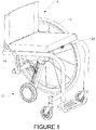
- FIGS 1 and 2 show an embodiment of the power assist system employing the motion-based push activation.
- the power assist system which in this embodiment comprises a single wheel power assist attachment 10, is shown mounted on a generic wheelchair 8, comprising a drive linkage 18, an electric hub drive wheel 20, a mounting attachment 22, and a remote control device 24.
- the single wheel power assist attachment 10 is positioned between the wheelchair drive wheels 16 such that the electric drive wheel 20 contacts the ground at a point midway between the wheelchair drive wheels 16. This positioning prevents the wheelchair from turning or drifting when an assistive force is provided, while not significantly hindering the rotation of the chair when desired for maneuvering.
- the single wheel power assist attachment 10 and drive linkage 18 are also angled such that as the drive wheel power is increased, the wheel digs into the ground for ideal traction control.
- the electric drive wheel 20 mounts to the distal end of the drive linkage 18, which is pivotally attached to the wheelchair axle bar 14 through the mounting attachment 22. While Figure 1 and Figure 2 show an embodiment with a singular mount attachment 22, in other embodiments a plurality or multitude of mounting attachments may be used to connect to the drive linkage 18.
- a remote control device 24 comprises part of the single wheel power assist attachment 10 to turn the unit on and modulate between multiple configuration settings for providing different amounts of driving force related to the sensed acceleration of the power assist system from the push of the user.
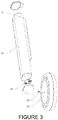
- the drive linkage 18 contains a shell or frame 30, a battery pack 32, custom printed circuit board 28, and electric hub motor 20.
- the primary role of the custom circuit board 28 is to receive sensor measurements, process those measurements to determine whether the users is pushing or braking, and then deliver the appropriate amount of power from the battery to the motor 20.
- Motion sensors can include inertial measurement units (gyroscopes, accelerometers and magnetometers) on the custom printed circuit board 28, rotational position sensors (optical encoders, Hall Effect sensors, or reed switches) in the drive motor 20, or inertial measurement units on the remote control device 24.
- Determining the linear acceleration of the wheelchair can be accomplished using several of these sensing modalities individually or with increased fidelity when done in combination to filter out any undesired motion artifacts, such as rolling over bumps or down slopes.
- the simplest method to derive linear acceleration of the wheelchair is to frequently sample the rotational position of the drive wheel 20 and differentiate discrete samples to derive the rotational speed and then differentiate rotational speed values to determine the rotational acceleration of the wheel.
- the linear acceleration of the wheelchair is directly related to the rotational acceleration of the drive wheel 20. Accelerations that occur when the power assist components are experiencing rapid changes in attitude (uphill/downhill angle) or vertical acceleration can be ignored as artifacts of environmental factors and not related to the user pushing or braking the wheelchair.
- Sensor measurements and motor power is passed to and from the printed circuit board 28 by cables that pass though the motor axle 26.
- Sensor measurements and configuration information from the remote control device 24 is passed to the printed circuit board 28 wirelessly using any of a number of standard data transmission protocols.
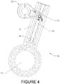
- the power assist unit 10 can be made to accommodate wheelchairs of varying rear wheel sizes by allowing the linkage pivot point to be adjusted along a slide pocket 36 in the drive linkage frame 30, as shown in Figure 4 .
- the pivot location can then be fixed by tightening machine screws in the pivot slider 34.
- the slide range can be limited using a stop in the slide track 38.
- the remote control device 24, shown removed from the wheelchair in Figure 5 can be made to slide onto the seat upholstery using a simple spring clip 40. In this embodiment, it can be quickly installed onto a wheelchair without the use of tools and it can be easily removed when the power assist is not needed.
- the remote can be used to turn the unit on using a button or switch 72.
- Another use for the remote is to allow the user to select between various modes of operation, such as LOW 42 and HIGH 44.
- Low and high modes can serve to decrease or increase the level of power delivered to the motor for any applied push. This can be accomplished by altering the multiplier used in setting the motor power in response to a measured acceleration. In an alternate approach, low and high modes could be used to limit the maximum drive speed of the motor for indoor and outdoor use.
- the motor assembly comprises a self-contained unit which includes a center shaft that fixable mounts the wheelchair to a stator.
- the motor housing has permanently mounted magnets and is rotationally driven by the push and pulling forces induced by the electrical excitation of the stator.
- the rotationally driven motor housing is connected to the tire supporting rim of the wheelchair wheel.
- the nature of this power assist system allows for the handrims to be directly mounted to the rim of the wheelchair drive wheels. As the user performs a push to the handrims, the wheelchair accelerates, activating the power assist through the motion-based recognition instrumentation.
- the instrumentation and motion control processing is similar to the previously described embodiment.
- the primary difference is that the rotational position of the two rear wheels would be measured directly and averaged to yield a single rotational position, which would then be processed as previously described.
- Each rear wheel would communicate wirelessly with the other in order to exchange rotational position information.
- Each drive wheel would be set to the same drive speed setting at the same time. Similarly, power to each drive wheel would be discontinued at the same time when a braking event is detected.
- motion-based push activation is incorporated into a wheelchair frame fixed drive system.
- the wheelchair wheels are secured to the wheelchair as normally done.
- Drive motors are then affixed to the frame of the wheelchair and the output shafts are pressed into the rear wheel tires to effectively couple their rotations together.
- the motor power is mechanically transferred to the rear wheels providing propulsion assistance.
- the mechanical means of transferring rotation from the drive motor to the rear wheels includes but is not limited to friction, gears, or belts, all of which is operationally well-known and need not be explained.
Claims (12)
- Bewegungsbasiertes Kraftunterstützungssystem für Rollstühle (8), mit:einem Bewegungserfassungssystem; undeinem Kraftunterstützungsantriebssystem mit einem einen Boden kontaktierenden elektrischen Nabenantriebsrad (20), das an einem distalen Ende einer Antriebsstange (18) montiert ist, und einer oder mehreren Klemmbefestigungen (22) zur Befestigung an einer Rollstuhlachse (14), wobei die Antriebsstange schwenkbar an der einen oder den mehreren Klemmbefestigungen angebracht ist,bei dem die Bewegung des Kraftunterstützungssystem als Eingabe für eine Aktivierung des Antriebssystems verwendet wird.
- Kraftunterstützungssystem nach Anspruch 1, bei dem der Antriebsstangenschwenkpunkt mittels eines Schwenkschiebers einstellbar ist, der sich in einer Schiebetasche in einem Antriebsstangenrahmen befindet, wobei die Position des Schwenkschiebers in der Schiebetasche fixierbar ist.
- Kraftunterstützungssystem nach einem der vorhergehenden Ansprüche, mit einer Fernsteuerungsvorrichtung (24).
- Kraftunterstützungssystem nach Anspruch 3, bei dem die Fernsteuerungsvorrichtung zum Steuern des Ausmaßes einer Kraft, die von dem Kraftunterstützungsantriebssystem bereitgestellt wird, und/oder der Antriebsgeschwindigkeit desselben angepasst ist.
- Kraftunterstützungssystem nach Anspruch 1, bei dem die Antriebsstange einen Rahmen oder eine Hülle, ein Batteriepack, einen elektrischen Nabenmotor und eine Leiterplatte aufweist.
- Kraftunterstützungssystem nach Anspruch 5, ferner mit einer Fernsteuerungsvorrichtung (24), die zur drahtlosen Kommunikation mit der Leiterplatte angepasst ist.
- Kraftunterstützungssystem nach Anspruch 1, bei dem das Bewegungserfassungssystem bewegungsempfindliche Instrumente zur Messung der Bewegung des Kraftunterstützungssystems aufweist.
- Kraftunterstützungssystem nach Anspruch 7, bei dem die bewegungsempfindlichen Instrumente Trägheitsmesseinheiten, Drehpositionssensoren oder Kombinationen daraus aufweisen.
- Kraftunterstützungssystem nach Anspruch 7, bei dem das Bewegungserfassungssystem die bewegungsbasierten Messungen zum Bestimmen, wenn der Rollstuhl geschoben oder gebremst wird, basierend darauf, ob eine detektierte Beschleunigung oder Verzögerung eine bestimmte Schwelle überschreitet, verwendet.
- Kraftunterstützungssystem nach Anspruch 9, bei dem das Bewegungserfassungssystem eine unterstützende Antriebskraft aktiviert, wenn ein Schub detektiert wird, und die Antriebskraft unterbricht, wenn eine Bremsung detektiert wird.
- Kraftunterstützungssystem nach Anspruch 10, bei dem das Ausmaß einer unterstützenden Antriebskraft auf der detektierten Beschleunigung basiert.
- Kraftunterstützungssystem nach Anspruch 11, bei dem der Anteil der unterstützenden Antriebskraft zwischen unterschiedlichen Konfigurationseinstellungen moduliert wird.
Priority Applications (1)
| Application Number | Priority Date | Filing Date | Title |
|---|---|---|---|
| EP21212912.6A EP4023199A1 (de) | 2011-07-06 | 2012-07-06 | Bewegungsbasiertes leistungsunterstützungssystem für rollstühle |
Applications Claiming Priority (3)
| Application Number | Priority Date | Filing Date | Title |
|---|---|---|---|
| US201161504949P | 2011-07-06 | 2011-07-06 | |
| EP12807785.6A EP2729108B1 (de) | 2011-07-06 | 2012-07-06 | Bewegungsbasiertes servosystem für rollstühle |
| PCT/US2012/045816 WO2013006818A2 (en) | 2011-07-06 | 2012-07-06 | Motion-based power assist system for wheelchairs |
Related Parent Applications (1)
| Application Number | Title | Priority Date | Filing Date |
|---|---|---|---|
| EP12807785.6A Division EP2729108B1 (de) | 2011-07-06 | 2012-07-06 | Bewegungsbasiertes servosystem für rollstühle |
Related Child Applications (1)
| Application Number | Title | Priority Date | Filing Date |
|---|---|---|---|
| EP21212912.6A Division EP4023199A1 (de) | 2011-07-06 | 2012-07-06 | Bewegungsbasiertes leistungsunterstützungssystem für rollstühle |
Publications (2)
| Publication Number | Publication Date |
|---|---|
| EP3260101A1 EP3260101A1 (de) | 2017-12-27 |
| EP3260101B1 true EP3260101B1 (de) | 2021-12-08 |
Family
ID=47437730
Family Applications (3)
| Application Number | Title | Priority Date | Filing Date |
|---|---|---|---|
| EP21212912.6A Pending EP4023199A1 (de) | 2011-07-06 | 2012-07-06 | Bewegungsbasiertes leistungsunterstützungssystem für rollstühle |
| EP12807785.6A Active EP2729108B1 (de) | 2011-07-06 | 2012-07-06 | Bewegungsbasiertes servosystem für rollstühle |
| EP17162833.2A Active EP3260101B1 (de) | 2011-07-06 | 2012-07-06 | Bewegungsbasiertes antriebsunterstützungssystem für rollstühle |
Family Applications Before (2)
| Application Number | Title | Priority Date | Filing Date |
|---|---|---|---|
| EP21212912.6A Pending EP4023199A1 (de) | 2011-07-06 | 2012-07-06 | Bewegungsbasiertes leistungsunterstützungssystem für rollstühle |
| EP12807785.6A Active EP2729108B1 (de) | 2011-07-06 | 2012-07-06 | Bewegungsbasiertes servosystem für rollstühle |
Country Status (4)
| Country | Link |
|---|---|
| US (4) | US9398990B2 (de) |
| EP (3) | EP4023199A1 (de) |
| ES (1) | ES2901153T3 (de) |
| WO (1) | WO2013006818A2 (de) |
Families Citing this family (41)
| Publication number | Priority date | Publication date | Assignee | Title |
|---|---|---|---|---|
| WO2013006818A2 (en) | 2011-07-06 | 2013-01-10 | Richter W Mark | Motion-based power assist system for wheelchairs |
| DE102012101136B3 (de) * | 2012-02-14 | 2013-07-04 | Leica Microsystems (Schweiz) Ag | Stativ zum Halten von mindestens einem medizinischen Gerät mit unterstützend angetriebenen Rollen |
| US10004651B2 (en) | 2012-09-18 | 2018-06-26 | Stryker Corporation | Patient support apparatus |
| US9259369B2 (en) | 2012-09-18 | 2016-02-16 | Stryker Corporation | Powered patient support apparatus |
| TWI480037B (zh) | 2012-12-27 | 2015-04-11 | Ind Tech Res Inst | 可拆裝動力模組 |
| JP6130674B2 (ja) * | 2013-01-15 | 2017-05-17 | 株式会社東芝 | 支援装置及び支援方法 |
| US9795522B2 (en) * | 2013-03-14 | 2017-10-24 | The Department Of Veterans Affairs | Collapsible manual wheelchair system for improved propulsion and transfers |
| US9144525B2 (en) * | 2013-03-14 | 2015-09-29 | Max Mobility, Llc. | Motion assistance system for wheelchairs |
| US9713559B2 (en) * | 2013-03-15 | 2017-07-25 | Stryker Corporation | Medical support apparatus |
| US9669858B2 (en) * | 2013-07-17 | 2017-06-06 | Cathy Washington | Remote controllable self-propelled stroller |
| US9498395B2 (en) | 2014-04-16 | 2016-11-22 | Stephen C. Golden, JR. | Joint movement detection device and system for coordinating motor output with manual wheelchair propulsion |
| US20150309508A1 (en) * | 2014-04-28 | 2015-10-29 | Kara Hasan Kubilay | Gyroscope Based Radio Transmitter for Model Vehicles |
| FR3020757A1 (fr) * | 2014-05-12 | 2015-11-13 | Centre Nat Rech Scient | Procede et dispositif d'aide a la propulsion electrique d'un systeme roulant, kit pour fauteuil roulant comportant un tel dispositif et fauteuil roulant equipe d'un tel dispositif. |
| DE102015116236A1 (de) | 2014-09-26 | 2016-03-31 | Edgar Ansmann | Rollstuhl mit Antrieb |
| US9682603B2 (en) | 2014-10-10 | 2017-06-20 | Max Mobility, Llc | System and method for adjusting a wheelchair seat |
| US9073399B1 (en) | 2014-10-10 | 2015-07-07 | Max Mobility, Llc | System and method for adjusting a wheelchair seat |
| US9358163B1 (en) | 2014-11-19 | 2016-06-07 | Charles E. Studebaker | Detachable electric drive unit for a wheelchair |
| US9795524B2 (en) | 2015-02-24 | 2017-10-24 | Max Mobility, Llc | Assistive driving system for a wheelchair |
| SE538936C2 (en) | 2015-06-16 | 2017-02-21 | Decon Wheel Ab | DRIVE UNIT FOR A WHEELCHAIR AND A WHEELCHAIR PROVIDED WITH SUCH A DRIVE UNIT |
| US10123921B2 (en) | 2015-07-24 | 2018-11-13 | Stryker Corporation | Patient support apparatus |
| US10568792B2 (en) | 2015-10-28 | 2020-02-25 | Stryker Corporation | Systems and methods for facilitating movement of a patient transport apparatus |
| US10603234B2 (en) | 2016-03-30 | 2020-03-31 | Stryker Corporation | Patient support apparatuses with drive systems |
| US9999557B2 (en) * | 2016-07-14 | 2018-06-19 | Challenging Solutions, Inc. | Robotic mobility device |
| WO2018013130A1 (en) * | 2016-07-15 | 2018-01-18 | Ford Global Technologies, Llc | Auxiliary power device |
| US10772774B2 (en) | 2016-08-10 | 2020-09-15 | Max Mobility, Llc | Self-balancing wheelchair |
| US9796401B1 (en) * | 2016-11-01 | 2017-10-24 | Michael Ammirati | Motorized wheel accessory for a stroller |
| CN106420202B (zh) * | 2016-11-03 | 2018-06-15 | 国家康复辅具研究中心 | 动平衡电动轮椅 |
| CN106859874B (zh) * | 2017-02-07 | 2018-07-06 | 晋江万智进出口贸易有限公司 | 一种能保持自平衡的智能轮椅 |
| US10335331B2 (en) * | 2017-03-31 | 2019-07-02 | Inventit Products, Inc. | Powered wheelchair, wheelchair powering device and method |
| CN106985608A (zh) * | 2017-04-14 | 2017-07-28 | 常州市吉庆机电有限公司 | 一种万向轮 |
| DE102017111127A1 (de) | 2017-05-22 | 2018-11-22 | Otto Bock Mobility Solutions Gmbh | Rollstuhl mit wenigstens einem elektrischen Hilfsantrieb |
| DE102017111129A1 (de) | 2017-05-22 | 2018-11-22 | Otto Bock Mobility Solutions Gmbh | Rollstuhl mit wenigstens einem elektrischen Hilfsantrieb |
| US10167051B1 (en) | 2017-12-12 | 2019-01-01 | Max Mobility, Llc | Assistive driving system for a wheelchair and method for controlling assistive driving system |
| DE102018122372A1 (de) * | 2018-09-13 | 2020-03-19 | Alber Gmbh | Antriebsvorrichtung für einen Rollstuhl |
| DE102018122359A1 (de) * | 2018-09-13 | 2020-03-19 | Alber Gmbh | Bediensatellit zur Ansteuerung einer Antriebsvorrichtung für einen Rollstuhl und Antriebsvorrichtung mit einem Bediensatelliten |
| DE102018122366A1 (de) | 2018-09-13 | 2020-03-19 | Alber Gmbh | Hilfsantriebsvorrichtung für einen Rollstuhl |
| US11863007B1 (en) * | 2019-12-11 | 2024-01-02 | Amazon Technologies, Inc. | Wheel-based charger for wireless smart controllers and carts |
| JP7327369B2 (ja) * | 2020-12-04 | 2023-08-16 | トヨタ自動車株式会社 | 電動アシスト装置およびプログラム |
| GB2610589A (en) * | 2021-09-08 | 2023-03-15 | One Rehab Ltd | Wheelchair driver |
| SE2130273A1 (en) * | 2021-10-11 | 2023-04-12 | Mercado Medic Ab | A personal movable chair and a method for controlling said chair |
| US20230190548A1 (en) * | 2021-12-20 | 2023-06-22 | Permobil, Inc. | System to adjust drive operation and performance in response to detection of a front add-on for a wheelchair |
Citations (14)
| Publication number | Priority date | Publication date | Assignee | Title |
|---|---|---|---|---|
| US4759418A (en) | 1986-02-24 | 1988-07-26 | Goldenfeld Ilia V | Wheelchair drive |
| US4770431A (en) | 1987-08-05 | 1988-09-13 | Helmut Kulik | Snap on wheel chair bicycle converter |
| US5113959A (en) | 1989-09-10 | 1992-05-19 | Propel Partnership 1987 | Electric drive attachment for a wheelchair |
| US5222567A (en) | 1991-04-26 | 1993-06-29 | Genus Inc. | Power assist device for a wheelchair |
| DE19539487A1 (de) | 1995-10-24 | 1997-04-30 | Alber Ulrich Gmbh | Antriebs- und Bremshilfsvorrichtung für Rollstühle |
| JPH10314234A (ja) | 1997-05-23 | 1998-12-02 | Tec Corp | 動力補助機付き車椅子 |
| DE19857786A1 (de) | 1998-03-21 | 1999-09-30 | Alber Ulrich Gmbh & Co Kg | Hilfsantriebsvorrichtung für Selbstfahrer-Rollstühle |
| DE19848530C1 (de) | 1998-10-21 | 2000-02-17 | Alber Ulrich Gmbh & Co Kg | Ansteuervorrichtung für Hilfsantriebsvorrichtungen für Selbstfahrer-Rollstühle |
| DE10046963C1 (de) | 2000-09-22 | 2001-12-06 | Alber Ulrich Gmbh & Co Kg | Fahrzeug, insbesondere Rollstuhl |
| US20030089537A1 (en) | 2001-11-09 | 2003-05-15 | Sinclair Sir Clive Marles | Wheelchair drive unit |
| US6729422B2 (en) | 2002-07-12 | 2004-05-04 | Simon Chu | Detachable transmission mechanism for a wheel chair and driving device thereof |
| JP2006081849A (ja) | 2004-09-17 | 2006-03-30 | Meidensha Corp | 補助車輪連結機構及び車椅子 |
| DE102007004704A1 (de) | 2007-01-31 | 2008-08-07 | Edgar Ansmann | Kinderwagen mit Elektroantrieb |
| US20100300777A1 (en) | 2009-05-27 | 2010-12-02 | Beach Mobility, Inc. | Power Add-On Device For Manual Wheelchair |
Family Cites Families (134)
| Publication number | Priority date | Publication date | Assignee | Title |
|---|---|---|---|---|
| DE300247C (de) | ||||
| US2448992A (en) | 1947-06-16 | 1948-09-07 | Love Homer | Propelling power unit for invalid wheel chairs |
| US2495573A (en) | 1948-10-13 | 1950-01-24 | Duke Samuel | Motor attachment for wheel chairs |
| JPS5214502B2 (de) * | 1973-07-27 | 1977-04-22 | ||
| US4207959A (en) | 1978-06-02 | 1980-06-17 | New York University | Wheelchair mounted control apparatus |
| US4260035A (en) | 1979-07-26 | 1981-04-07 | The Johns Hopkins University | Chin controller system for powered wheelchair |
| US4386672A (en) * | 1981-06-11 | 1983-06-07 | Coker Theodore R | Detachable electric drive unit for wheelchair |
| US4422515A (en) | 1981-07-29 | 1983-12-27 | The United States of America as represented by the Admin. of Veterans Affairs | Motorized wheel chair |
| US4652026A (en) | 1984-01-18 | 1987-03-24 | Byrge Jerome J | Manual propulsion apparatus for wheelchairs |
| US4926952A (en) | 1984-05-01 | 1990-05-22 | Jeffrey Farnam | Four-wheel drive wheelchair with compound wheels |
| US4823900A (en) | 1984-05-01 | 1989-04-25 | Jeffrey Farnam | Four-wheel drive wheel-chair with compound wheels |
| JPS634205A (ja) | 1986-06-24 | 1988-01-09 | Canon Inc | 位相回折格子型光変調素子のグレ−テイングの製造方法 |
| US4728812A (en) | 1986-07-07 | 1988-03-01 | Sheriff Paul S | Oral machine controller |
| US4767940A (en) | 1987-10-02 | 1988-08-30 | Peachtree Patient Center, Inc. | Electronic sensing and control circuit |
| GB2223994A (en) | 1988-09-15 | 1990-04-25 | Walter Neol Powell | Drive apparatus |
| US5016720A (en) * | 1989-06-02 | 1991-05-21 | Coker Theodore R | Detachable electric drive unit for collapsible wheelchair |
| JPH0485501A (ja) | 1990-07-30 | 1992-03-18 | Alps Electric Co Ltd | レンズならびにレンズの製造方法 |
| US5135063A (en) | 1990-08-30 | 1992-08-04 | Smucker Manufacturing, Inc. | Power unit for driving manually-operated wheelchair |
| US5234066A (en) * | 1990-11-13 | 1993-08-10 | Staodyn, Inc. | Power-assisted wheelchair |
| US5244051A (en) * | 1991-11-04 | 1993-09-14 | Wu Kung Hsiung | Central steerable driving means of wheelchair |
| US5555949A (en) * | 1992-02-18 | 1996-09-17 | Cerebral Palsy Research Foundation Of Kansas | Electricaly operable wheelchair having a controller responsive to different types of inputs |
| US5351774A (en) | 1992-06-02 | 1994-10-04 | Quickie Designs Inc. | Powered wheelchair with a detachable power drive assembly |
| US5366037A (en) * | 1992-11-23 | 1994-11-22 | Invacare Corporation | Powered wheelchair having drive motors integrated into driven wheels |
| GB2274265A (en) | 1993-01-13 | 1994-07-20 | Richard Craddock Hayes | Power drive assembly for attachment to a wheelchair. |
| JPH06304205A (ja) * | 1993-04-19 | 1994-11-01 | Nabco Ltd | 電動車両 |
| DE4323937C1 (de) | 1993-07-16 | 1994-11-24 | Christian Klepsch | Elektrisch angetriebener Rollstuhl |
| US5651422A (en) * | 1994-04-22 | 1997-07-29 | The Center For Innovative Technology | Universal-fit, quick-connect power drive/steer attachment for wheelchair |
| US5494126A (en) * | 1994-06-02 | 1996-02-27 | Meeker; Galen L. | Apparatus and method for attaching a motorized wheel to a wheelchair |
| JP3661882B2 (ja) * | 1994-06-16 | 2005-06-22 | ヤマハ発動機株式会社 | 補助動力式ビークル |
| JP3703524B2 (ja) * | 1995-06-20 | 2005-10-05 | ヤマハ発動機株式会社 | 手動式電動車椅子 |
| JP3524640B2 (ja) * | 1995-07-31 | 2004-05-10 | 三洋電機株式会社 | 車いす |
| JP3703554B2 (ja) * | 1996-02-14 | 2005-10-05 | ヤマハ発動機株式会社 | 補助動力付き車椅子 |
| JPH09285501A (ja) | 1996-04-24 | 1997-11-04 | Tec Corp | 電動車椅子 |
| JP3705378B2 (ja) * | 1996-07-01 | 2005-10-12 | ヤマハ発動機株式会社 | 電動車椅子 |
| US5826670A (en) * | 1996-08-15 | 1998-10-27 | Nan; Huang Shun | Detachable propulsive device for wheelchair |
| JPH1099379A (ja) * | 1996-09-27 | 1998-04-21 | Yamaha Motor Co Ltd | 補助動力付き車椅子 |
| US6112837A (en) * | 1996-09-30 | 2000-09-05 | Yamaha Hatsudoki Kabushiki Kaisha | Manually operated, motor assisted wheelchair |
| JPH10314232A (ja) * | 1997-05-19 | 1998-12-02 | Yamaha Motor Co Ltd | 補助動力式車椅子 |
| DE19748201C1 (de) | 1997-10-31 | 1999-03-04 | Alber Ulrich Gmbh | Nabenantriebsvorrichtung |
| US6416063B1 (en) | 1998-01-28 | 2002-07-09 | Scott H. Stillinger | High performance skate |
| JP2990358B1 (ja) | 1998-09-11 | 1999-12-13 | 新明工業株式会社 | 手動式の車椅子 |
| US6334497B2 (en) | 1998-09-18 | 2002-01-01 | George V. Odell | Wheelchair motorizing apparatus |
| US6290014B1 (en) * | 1999-02-09 | 2001-09-18 | Maccready, Jr. Paul B. | Power assist for bicycles |
| JP4564175B2 (ja) | 1999-03-15 | 2010-10-20 | デカ・プロダクツ・リミテッド・パートナーシップ | 車椅子用制御システム及び方法 |
| DE29907846U1 (de) | 1999-05-04 | 1999-09-09 | Mobile Power Systems Michael B | Elektrische Schubhilfe für Faltrollstühle |
| JP2003517808A (ja) * | 1999-08-31 | 2003-05-27 | デルタグライド、インコーポレイテッド | 動力補助車両 |
| JP2001327544A (ja) | 2000-03-15 | 2001-11-27 | Fuji Heavy Ind Ltd | 車椅子の補助動力装置 |
| US6729421B1 (en) * | 2000-06-06 | 2004-05-04 | Kaback Enterprises Inc. | Motor-assist gurney unit and method |
| US7566102B2 (en) | 2000-09-21 | 2009-07-28 | Innowheel Pty Ltd. | Multiple roller wheel |
| US6360836B1 (en) * | 2000-09-29 | 2002-03-26 | Seitz Corporation | Add-on drive assembly for baby strollers and carriages |
| US6554086B1 (en) | 2000-10-27 | 2003-04-29 | Invacare Corporation | Obstacle traversing wheelchair |
| AU2002255568B8 (en) | 2001-02-20 | 2014-01-09 | Adidas Ag | Modular personal network systems and methods |
| US20020171559A1 (en) | 2001-05-15 | 2002-11-21 | Tai-Her Yang | Wrist & hand-held wireless or wired control device |
| JP2003052760A (ja) | 2001-08-09 | 2003-02-25 | Fuji Heavy Ind Ltd | 車椅子の補助動力制御装置 |
| RU2296075C2 (ru) | 2001-10-03 | 2007-03-27 | Галилео Мобилити Инструментс Лтд. | Ходовая система для средства передвижения |
| US7040429B2 (en) | 2001-10-10 | 2006-05-09 | Invacare Corporation | Wheelchair suspension |
| US6971471B2 (en) * | 2001-12-07 | 2005-12-06 | General Motors Corporation | Multi-directional drive |
| US20070145711A1 (en) | 2002-04-30 | 2007-06-28 | Mulhern James P | Rear wheel drive vehicle with ground-contacting anti-tip wheels |
| JP4511344B2 (ja) | 2002-06-11 | 2010-07-28 | デカ・プロダクツ・リミテッド・パートナーシップ | 使用者によって推進される車椅子および車椅子を推進する方法 |
| US20080300777A1 (en) | 2002-07-02 | 2008-12-04 | Linda Fehr | Computer-controlled power wheelchair navigation system |
| US6842692B2 (en) | 2002-07-02 | 2005-01-11 | The United States Of America As Represented By The Department Of Veterans Affairs | Computer-controlled power wheelchair navigation system |
| JP3928501B2 (ja) | 2002-07-03 | 2007-06-13 | リコープリンティングシステムズ株式会社 | シート取扱システム |
| TW530645U (en) * | 2002-07-12 | 2003-05-01 | Simon Chu | Detachable transmission mechanism for a wheel chair |
| KR20020067456A (ko) | 2002-07-13 | 2002-08-22 | 임락복 | 무한궤도 전륜형 수동/전동 겸용 휠체어 |
| GB2393162A (en) | 2002-09-16 | 2004-03-24 | Russ Critcher | Folding wheelchair with detachable power assistance unit |
| US7293801B2 (en) | 2003-08-18 | 2007-11-13 | Invacare Corporation | Self-stabilizing suspension for wheeled vehicles |
| TW583968U (en) | 2003-06-13 | 2004-04-11 | Pihsiang Machinery Mfg Co Ltd | Suspension structure of independent front guide wheel for wheelchair |
| US7234554B2 (en) | 2003-07-02 | 2007-06-26 | Pride Mobility Products Corporation | Rear wheel drive power wheelchair |
| NL1023836C2 (nl) | 2003-07-07 | 2005-01-10 | Indes Holding Bv | Rolstoel en bedieningsmiddelen ten gebruike in een dergelijke rolstoel. |
| CA2484325C (en) | 2003-10-08 | 2013-09-10 | Pride Mobility Products Corporation | Active anti-tip system for power wheelchairs |
| US7232008B2 (en) | 2003-10-08 | 2007-06-19 | Pride Mobility Products Corporation | Active anti-tip wheels for power wheelchair |
| US20050137652A1 (en) | 2003-12-19 | 2005-06-23 | The Board of Regents of the University of Texas at Dallas | System and method for interfacing cellular matter with a machine |
| US6880661B1 (en) * | 2004-02-26 | 2005-04-19 | Steve Oh | Detachable motor drive for a bicycle |
| US7264272B2 (en) | 2004-03-16 | 2007-09-04 | Pride Mobility Products Corporation | Bi-directional anti-tip system for powered wheelchairs |
| NL1025807C2 (nl) | 2004-03-25 | 2005-09-27 | Indes Holding Bv | Rolstoel en draagwiel voorzien van een wielmotor ten gebruike in een dergelijke rolstoel. |
| US20050236208A1 (en) | 2004-04-27 | 2005-10-27 | Richard Runkles | Power wheelchair |
| NL1026282C2 (nl) | 2004-05-27 | 2005-11-30 | Exact Dynamics B V | Rolstoel met mechanische arm. |
| CN101001595B (zh) | 2004-08-04 | 2012-03-07 | 乔汉森诺米尼斯控股有限公司 | 双模式轮椅 |
| US7138774B2 (en) | 2004-08-05 | 2006-11-21 | Yamaha Hatsudoki Kabushiki Kaisha | Vehicle control unit and vehicle |
| DE102005006574B3 (de) * | 2005-02-11 | 2006-09-21 | Barthelt, Hans-Peter, Dipl.-Ing. | Rollstuhl mit Fernbedienung |
| TWI285547B (en) | 2005-02-16 | 2007-08-21 | Kwang Yang Motor Co | Fixed speed control device of electric wheelchair |
| ATE520384T1 (de) | 2005-06-24 | 2011-09-15 | Degonda Rehab Sa | Rollstuhl mit mittenradantrieb |
| AU2006270274A1 (en) | 2005-07-14 | 2007-01-25 | Pride Mobility Products Corporation | Powered wheelchair configurations and related methods of use |
| JP4993883B2 (ja) | 2005-07-20 | 2012-08-08 | ヤマハ発動機株式会社 | 回転電機及び電動車椅子 |
| US7896394B2 (en) | 2005-08-18 | 2011-03-01 | Sunrise Medical Hhg, Inc. | Midwheel drive wheelchair with independent front and rear suspension |
| US7403844B2 (en) | 2005-08-31 | 2008-07-22 | Invacare Corporation | Method and apparatus for programming parameters of a power driven wheelchair for a plurality of drive settings |
| DE102005043524B3 (de) * | 2005-09-13 | 2007-04-26 | Pihsiang Machinery Mfg. Co., Ltd., Hsin Feng Hsiang | Betätigungsmechanismus eines Hilfsmotors von Rollstühlen |
| SE528665C2 (sv) | 2005-10-18 | 2007-01-16 | Permobil Ab | Anordning för uppbärande av gods vid en rullstol |
| US20070095580A1 (en) | 2005-10-27 | 2007-05-03 | Sunpex Technology Co., Ltd. | Power wheelchair with clutch control device |
| WO2007079346A2 (en) | 2005-12-30 | 2007-07-12 | Olsen Christopher J | Articulated wheel assemblies and vehicles therewith |
| WO2007106874A2 (en) * | 2006-03-14 | 2007-09-20 | Autocraft Industries, Inc. | Improved wheelchair |
| JP4117798B2 (ja) | 2006-05-11 | 2008-07-16 | 関東自動車工業株式会社 | 電動車椅子 |
| US7938434B2 (en) | 2006-06-08 | 2011-05-10 | Smith Joel N | Foldable wheelchair frame |
| US7476102B2 (en) | 2006-06-09 | 2009-01-13 | Maples Paul D | Contamination avoiding device |
| US8292678B2 (en) | 2006-06-28 | 2012-10-23 | Burgess Jr Donald Wesley | Personal propulsion device with hands free control |
| US7882909B2 (en) * | 2006-09-14 | 2011-02-08 | University Of Pittsburgh | Personal vehicle |
| EP1972486A1 (de) | 2007-03-19 | 2008-09-24 | Invacare International Sàrl | Motorisierter Rollstuhl |
| WO2008121316A1 (en) | 2007-03-31 | 2008-10-09 | Daedalus Wings, Inc. | Wheelchair drive system with lever propulsion and a hub-contained transmission |
| US8306673B1 (en) | 2007-04-20 | 2012-11-06 | Manning Doug | Electronic controls and options for powered riding machines |
| GB0708834D0 (en) | 2007-05-08 | 2007-06-13 | Dugas Eric | Motorized base for a mid-wheel power drive wheelchair |
| TW200908949A (en) | 2007-08-23 | 2009-03-01 | Merits Health Products Co Ltd | Electric wheelchair |
| JP2009078044A (ja) | 2007-09-27 | 2009-04-16 | Hiroshi Yukitoshi | 車イス用駆動補助装置 |
| US9002680B2 (en) | 2008-06-13 | 2015-04-07 | Nike, Inc. | Foot gestures for computer input and interface control |
| US7886854B2 (en) * | 2008-07-18 | 2011-02-15 | Wu's Tech Co., Ltd. | Wheelchair |
| DE102008002993B3 (de) | 2008-08-08 | 2009-11-05 | Ulrich Alber Gmbh | Hilfsantriebsvorrichtung für einen Rollstuhl und Rollstuhl mit Hilfsantriebsvorrichtung |
| US8038165B2 (en) | 2008-10-08 | 2011-10-18 | Arthur Wang | Device for allowing a wheeled vehicle for individuals to be dragged in a folded configuration |
| US8556279B2 (en) | 2008-12-08 | 2013-10-15 | Peter Rodney McKinnon | Handtruck |
| US8960340B2 (en) | 2009-05-27 | 2015-02-24 | Patrick Tallino | Power add-on device for manual wheelchair |
| JP5398446B2 (ja) | 2009-09-18 | 2014-01-29 | 本田技研工業株式会社 | 駆動装置 |
| US7976049B2 (en) | 2009-11-05 | 2011-07-12 | Wu's Tech Co., Ltd. | Assembly and positioning mechanism for wheelchair and auxiliary operating lever |
| US8261867B1 (en) * | 2009-12-30 | 2012-09-11 | Gainer Della R | Wheeled vehicle drive apparatus |
| TW201121531A (en) * | 2009-12-31 | 2011-07-01 | xiang-ling Xu | Auxiliary driving device for wheelchair. |
| US8602138B2 (en) * | 2010-02-25 | 2013-12-10 | Paul Filkoski | Motorized anti-tipper device |
| US20110304121A1 (en) * | 2010-06-11 | 2011-12-15 | Wu's Tech Co., Ltd. | Quick-release mechanism |
| US8851214B2 (en) | 2010-07-15 | 2014-10-07 | Permobil Ab | Electric mid-wheel drive wheelchair |
| DE202010017965U1 (de) | 2010-09-22 | 2013-05-02 | Ulrich Alber Gmbh | Hilfsantriebsvorrichtung, Rollstuhl und Vorrichtung zur Ermittlung von physischen Leistungsdaten eines Rollstuhlfahrers |
| ITTO20110891A1 (it) * | 2010-10-05 | 2012-04-06 | Pride Mobility Products Corp | Gruppo motore amovibile per sedie a rotelle |
| US8761963B2 (en) | 2010-12-01 | 2014-06-24 | John Hinkel, III | Wheelchair guiding |
| US8572764B2 (en) | 2010-12-09 | 2013-11-05 | Dieter Thellmann | Exercising glove |
| WO2013006818A2 (en) | 2011-07-06 | 2013-01-10 | Richter W Mark | Motion-based power assist system for wheelchairs |
| WO2013123119A1 (en) | 2012-02-15 | 2013-08-22 | Stryker Corporation | Patient support apparatus and controls therefor |
| US8775001B2 (en) | 2012-02-17 | 2014-07-08 | Alan C. Phillips | Motorized wheelchair interlock |
| JP6115893B2 (ja) | 2012-03-26 | 2017-04-19 | アイシン精機株式会社 | パーソナルビークル制御装置 |
| US9144525B2 (en) * | 2013-03-14 | 2015-09-29 | Max Mobility, Llc. | Motion assistance system for wheelchairs |
| KR20150089860A (ko) | 2014-01-28 | 2015-08-05 | 이원우 | 동작 인식 전동 휠체어 |
| US9498395B2 (en) | 2014-04-16 | 2016-11-22 | Stephen C. Golden, JR. | Joint movement detection device and system for coordinating motor output with manual wheelchair propulsion |
| US20150357948A1 (en) | 2014-06-05 | 2015-12-10 | Kevin W. Goldstein | Hand Worn Wireless Remote Controller For Motors |
| US9795524B2 (en) * | 2015-02-24 | 2017-10-24 | Max Mobility, Llc | Assistive driving system for a wheelchair |
| US10687707B2 (en) | 2016-06-07 | 2020-06-23 | Apple Inc. | Detecting activity by a wheelchair user |
| US9796401B1 (en) * | 2016-11-01 | 2017-10-24 | Michael Ammirati | Motorized wheel accessory for a stroller |
| US10167051B1 (en) * | 2017-12-12 | 2019-01-01 | Max Mobility, Llc | Assistive driving system for a wheelchair and method for controlling assistive driving system |
| ES2737728B2 (es) * | 2018-07-05 | 2021-02-25 | Genius Emobility Systems Sl | Sistema de propulsion para carros mediante patinete electrico de tipo hoverboard acoplado a traves de una estructura articulada |
| DE102018122360A1 (de) * | 2018-09-13 | 2020-03-19 | Alber Gmbh | Hilfsantriebsvorrichtung für einen Rollstuhl |
| DE102018122367A1 (de) * | 2018-09-13 | 2020-03-19 | Alber Gmbh | Antriebsvorrichtung für einen Rollstuhl |
-
2012
- 2012-07-06 WO PCT/US2012/045816 patent/WO2013006818A2/en active Application Filing
- 2012-07-06 EP EP21212912.6A patent/EP4023199A1/de active Pending
- 2012-07-06 EP EP12807785.6A patent/EP2729108B1/de active Active
- 2012-07-06 EP EP17162833.2A patent/EP3260101B1/de active Active
- 2012-07-06 US US13/543,598 patent/US9398990B2/en active Active
- 2012-07-06 ES ES17162833T patent/ES2901153T3/es active Active
-
2016
- 2016-07-25 US US15/218,937 patent/US11065166B2/en active Active
-
2021
- 2021-06-08 US US17/342,104 patent/US11813209B2/en active Active
-
2023
- 2023-11-10 US US18/506,706 patent/US20240074924A1/en active Pending
Patent Citations (15)
| Publication number | Priority date | Publication date | Assignee | Title |
|---|---|---|---|---|
| US4759418A (en) | 1986-02-24 | 1988-07-26 | Goldenfeld Ilia V | Wheelchair drive |
| US4770431A (en) | 1987-08-05 | 1988-09-13 | Helmut Kulik | Snap on wheel chair bicycle converter |
| US5113959A (en) | 1989-09-10 | 1992-05-19 | Propel Partnership 1987 | Electric drive attachment for a wheelchair |
| US5222567A (en) | 1991-04-26 | 1993-06-29 | Genus Inc. | Power assist device for a wheelchair |
| DE19539487A1 (de) | 1995-10-24 | 1997-04-30 | Alber Ulrich Gmbh | Antriebs- und Bremshilfsvorrichtung für Rollstühle |
| JPH10314234A (ja) | 1997-05-23 | 1998-12-02 | Tec Corp | 動力補助機付き車椅子 |
| DE19857786A1 (de) | 1998-03-21 | 1999-09-30 | Alber Ulrich Gmbh & Co Kg | Hilfsantriebsvorrichtung für Selbstfahrer-Rollstühle |
| DE19848530C1 (de) | 1998-10-21 | 2000-02-17 | Alber Ulrich Gmbh & Co Kg | Ansteuervorrichtung für Hilfsantriebsvorrichtungen für Selbstfahrer-Rollstühle |
| DE10046963C1 (de) | 2000-09-22 | 2001-12-06 | Alber Ulrich Gmbh & Co Kg | Fahrzeug, insbesondere Rollstuhl |
| US20030089537A1 (en) | 2001-11-09 | 2003-05-15 | Sinclair Sir Clive Marles | Wheelchair drive unit |
| US6729422B2 (en) | 2002-07-12 | 2004-05-04 | Simon Chu | Detachable transmission mechanism for a wheel chair and driving device thereof |
| JP2006081849A (ja) | 2004-09-17 | 2006-03-30 | Meidensha Corp | 補助車輪連結機構及び車椅子 |
| DE102007004704A1 (de) | 2007-01-31 | 2008-08-07 | Edgar Ansmann | Kinderwagen mit Elektroantrieb |
| US20100300777A1 (en) | 2009-05-27 | 2010-12-02 | Beach Mobility, Inc. | Power Add-On Device For Manual Wheelchair |
| US8430189B2 (en) | 2009-05-27 | 2013-04-30 | Patrick Tallino | Power add-on device for manual wheelchair |
Non-Patent Citations (7)
| Title |
|---|
| ANONYMOUS: "Smart Drive MX 2+ Rollstuhlzusatzantrieb Betriebsanleitung", MAX MOBILITY, LLC |
| DANIEL PETERSSON ; JONAS JOHANSSON ; ULF HOLMBERG ; BJORN ASTRAND: "Torque Sensor Free Power Assisted Wheelchair", REHABILITATION ROBOTICS, 2007. ICORR 2007. IEEE 10TH INTERNATIONAL CON FERENCE ON, IEEE, PI, 1 June 2007 (2007-06-01), Pi , pages 151 - 157, XP031200707, ISBN: 978-1-4244-1319-5 |
| DEUTSCHE NORM: "Elektrorollstuhle und -mobile und zugehorige Ladegerate - Anforderungen und Prufverfahren; Deutsche Fassung EN 12184:2014", DIN EN 12184, 1 June 2014 (2014-06-01), pages 1 - 64, XP055450572, [retrieved on 20180213] |
| JOHANSSON JONAS, PETERSSON DANIEL: "Torque Sensor Free Power Assisted Wheelchair", MASTER'S THESIS IN ELECTRICAL ENGINEERING, 1 January 2007 (2007-01-01), pages i - 67, XP055962890, Retrieved from the Internet <URL:https://www.diva-portal.org/smash/get/diva2:237836/FULLTEXT01.pdf> [retrieved on 20220920] |
| MIYAZAWA T., KATSURA S., OHNISHI K.: "A power-assisted wheelchair taking running environment into account", THE 29TH ANNUAL CONFERENCE OF THE IEEE INDUSTRIAL ELECTRONICS SOCIETY, 2003. IECON '03., IEEE SERVICE CENTER, PISCATAWAY, NJ, vol. 2, 2 November 2003 (2003-11-02) - 6 November 2003 (2003-11-06), Piscataway, NJ , pages 1343 - 1348, XP010691084, ISBN: 978-0-7803-7906-0, DOI: 10.1109/IECON.2003.1280252 |
| RICK N ROBERTSON, ET AL: "Pushrim forces and joint kinetics during wheelchair propulsion", ARCHIVES OF PHYSICAL MEDICINE AND REHABILITATION, ELSEVIER, AMSTERDAM, NL, vol. 77, no. 9, 1 September 1996 (1996-09-01), AMSTERDAM, NL , pages 856 - 864, XP055449220, ISSN: 0003-9993, DOI: 10.1016/S0003-9993(96)90270-1 |
| SEHOON OH, HORI Y.: "Sensor Free Power Assisting Control Based on Velocity Control and Disturbance Observer", INDUSTRIAL ELECTRONICS, 2005. ISIE 2005. PROCEEDINGS OF THE IEEE INTER NATIONAL SYMPOSIUM ON DUBROVNIK, CROATIA JUNE 20-23, 2005, PISCATAWAY, NJ, USA,IEEE, vol. 4, 20 June 2005 (2005-06-20) - 23 June 2005 (2005-06-23), pages 1709 - 1714, XP010850351, ISBN: 978-0-7803-8738-6, DOI: 10.1109/ISIE.2005.1529190 |
Also Published As
| Publication number | Publication date |
|---|---|
| US20130008732A1 (en) | 2013-01-10 |
| WO2013006818A2 (en) | 2013-01-10 |
| WO2013006818A3 (en) | 2013-04-25 |
| EP2729108A2 (de) | 2014-05-14 |
| US20210169716A1 (en) | 2021-06-10 |
| EP4023199A1 (de) | 2022-07-06 |
| US11813209B2 (en) | 2023-11-14 |
| US9398990B2 (en) | 2016-07-26 |
| EP2729108B1 (de) | 2017-03-29 |
| ES2901153T3 (es) | 2022-03-21 |
| US20210338500A1 (en) | 2021-11-04 |
| US20240074924A1 (en) | 2024-03-07 |
| US11065166B2 (en) | 2021-07-20 |
| EP2729108A4 (de) | 2015-07-08 |
| EP3260101A1 (de) | 2017-12-27 |
Similar Documents
| Publication | Publication Date | Title |
|---|---|---|
| US11813209B2 (en) | Motion-based power assist system for wheelchairs | |
| EP3970677B1 (de) | Unterstützendes antriebssystem für einen rollstuhl | |
| US10034803B2 (en) | Motion assistance system for wheelchairs | |
| US10058765B2 (en) | Self-balancing board with primary wheel and distal auxiliary wheel | |
| US11220173B2 (en) | Powered wheel assemblies and control systems | |
| US11198052B2 (en) | Cross skate system and method of operation thereof | |
| US20190298601A1 (en) | Rollator Having Auto Brake System |
Legal Events
| Date | Code | Title | Description |
|---|---|---|---|
| PUAI | Public reference made under article 153(3) epc to a published international application that has entered the european phase |
Free format text: ORIGINAL CODE: 0009012 |
|
| STAA | Information on the status of an ep patent application or granted ep patent |
Free format text: STATUS: THE APPLICATION HAS BEEN PUBLISHED |
|
| AC | Divisional application: reference to earlier application |
Ref document number: 2729108 Country of ref document: EP Kind code of ref document: P |
|
| AK | Designated contracting states |
Kind code of ref document: A1 Designated state(s): AL AT BE BG CH CY CZ DE DK EE ES FI FR GB GR HR HU IE IS IT LI LT LU LV MC MK MT NL NO PL PT RO RS SE SI SK SM TR |
|
| RAP1 | Party data changed (applicant data changed or rights of an application transferred) |
Owner name: MAX MOBILITY, LLC |
|
| RIN1 | Information on inventor provided before grant (corrected) |
Inventor name: RICHTER, WILLIAM MARK |
|
| STAA | Information on the status of an ep patent application or granted ep patent |
Free format text: STATUS: REQUEST FOR EXAMINATION WAS MADE |
|
| 17P | Request for examination filed |
Effective date: 20180524 |
|
| RBV | Designated contracting states (corrected) |
Designated state(s): AL AT BE BG CH CY CZ DE DK EE ES FI FR GB GR HR HU IE IS IT LI LT LU LV MC MK MT NL NO PL PT RO RS SE SI SK SM TR |
|
| STAA | Information on the status of an ep patent application or granted ep patent |
Free format text: STATUS: EXAMINATION IS IN PROGRESS |
|
| 17Q | First examination report despatched |
Effective date: 20190114 |
|
| RAP1 | Party data changed (applicant data changed or rights of an application transferred) |
Owner name: MAX MOBILITY, LLC |
|
| RIC1 | Information provided on ipc code assigned before grant |
Ipc: A61G 5/04 20130101AFI20200514BHEP |
|
| GRAP | Despatch of communication of intention to grant a patent |
Free format text: ORIGINAL CODE: EPIDOSNIGR1 |
|
| STAA | Information on the status of an ep patent application or granted ep patent |
Free format text: STATUS: GRANT OF PATENT IS INTENDED |
|
| INTG | Intention to grant announced |
Effective date: 20200622 |
|
| GRAJ | Information related to disapproval of communication of intention to grant by the applicant or resumption of examination proceedings by the epo deleted |
Free format text: ORIGINAL CODE: EPIDOSDIGR1 |
|
| STAA | Information on the status of an ep patent application or granted ep patent |
Free format text: STATUS: EXAMINATION IS IN PROGRESS |
|
| INTC | Intention to grant announced (deleted) | ||
| GRAP | Despatch of communication of intention to grant a patent |
Free format text: ORIGINAL CODE: EPIDOSNIGR1 |
|
| STAA | Information on the status of an ep patent application or granted ep patent |
Free format text: STATUS: GRANT OF PATENT IS INTENDED |
|
| INTG | Intention to grant announced |
Effective date: 20210622 |
|
| GRAS | Grant fee paid |
Free format text: ORIGINAL CODE: EPIDOSNIGR3 |
|
| GRAA | (expected) grant |
Free format text: ORIGINAL CODE: 0009210 |
|
| STAA | Information on the status of an ep patent application or granted ep patent |
Free format text: STATUS: THE PATENT HAS BEEN GRANTED |
|
| AC | Divisional application: reference to earlier application |
Ref document number: 2729108 Country of ref document: EP Kind code of ref document: P |
|
| AK | Designated contracting states |
Kind code of ref document: B1 Designated state(s): AL AT BE BG CH CY CZ DE DK EE ES FI FR GB GR HR HU IE IS IT LI LT LU LV MC MK MT NL NO PL PT RO RS SE SI SK SM TR |
|
| REG | Reference to a national code |
Ref country code: GB Ref legal event code: FG4D |
|
| REG | Reference to a national code |
Ref country code: AT Ref legal event code: REF Ref document number: 1453203 Country of ref document: AT Kind code of ref document: T Effective date: 20211215 Ref country code: CH Ref legal event code: EP |
|
| REG | Reference to a national code |
Ref country code: DE Ref legal event code: R096 Ref document number: 602012077338 Country of ref document: DE |
|
| REG | Reference to a national code |
Ref country code: IE Ref legal event code: FG4D |
|
| REG | Reference to a national code |
Ref country code: NL Ref legal event code: FP |
|
| REG | Reference to a national code |
Ref country code: SE Ref legal event code: TRGR |
|
| REG | Reference to a national code |
Ref country code: ES Ref legal event code: FG2A Ref document number: 2901153 Country of ref document: ES Kind code of ref document: T3 Effective date: 20220321 Ref country code: NO Ref legal event code: T2 Effective date: 20211208 |
|
| REG | Reference to a national code |
Ref country code: LT Ref legal event code: MG9D |
|
| PG25 | Lapsed in a contracting state [announced via postgrant information from national office to epo] |
Ref country code: RS Free format text: LAPSE BECAUSE OF FAILURE TO SUBMIT A TRANSLATION OF THE DESCRIPTION OR TO PAY THE FEE WITHIN THE PRESCRIBED TIME-LIMIT Effective date: 20211208 Ref country code: LT Free format text: LAPSE BECAUSE OF FAILURE TO SUBMIT A TRANSLATION OF THE DESCRIPTION OR TO PAY THE FEE WITHIN THE PRESCRIBED TIME-LIMIT Effective date: 20211208 Ref country code: FI Free format text: LAPSE BECAUSE OF FAILURE TO SUBMIT A TRANSLATION OF THE DESCRIPTION OR TO PAY THE FEE WITHIN THE PRESCRIBED TIME-LIMIT Effective date: 20211208 Ref country code: BG Free format text: LAPSE BECAUSE OF FAILURE TO SUBMIT A TRANSLATION OF THE DESCRIPTION OR TO PAY THE FEE WITHIN THE PRESCRIBED TIME-LIMIT Effective date: 20220308 |
|
| REG | Reference to a national code |
Ref country code: AT Ref legal event code: MK05 Ref document number: 1453203 Country of ref document: AT Kind code of ref document: T Effective date: 20211208 |
|
| PG25 | Lapsed in a contracting state [announced via postgrant information from national office to epo] |
Ref country code: LV Free format text: LAPSE BECAUSE OF FAILURE TO SUBMIT A TRANSLATION OF THE DESCRIPTION OR TO PAY THE FEE WITHIN THE PRESCRIBED TIME-LIMIT Effective date: 20211208 Ref country code: HR Free format text: LAPSE BECAUSE OF FAILURE TO SUBMIT A TRANSLATION OF THE DESCRIPTION OR TO PAY THE FEE WITHIN THE PRESCRIBED TIME-LIMIT Effective date: 20211208 Ref country code: GR Free format text: LAPSE BECAUSE OF FAILURE TO SUBMIT A TRANSLATION OF THE DESCRIPTION OR TO PAY THE FEE WITHIN THE PRESCRIBED TIME-LIMIT Effective date: 20220309 |
|
| PG25 | Lapsed in a contracting state [announced via postgrant information from national office to epo] |
Ref country code: SM Free format text: LAPSE BECAUSE OF FAILURE TO SUBMIT A TRANSLATION OF THE DESCRIPTION OR TO PAY THE FEE WITHIN THE PRESCRIBED TIME-LIMIT Effective date: 20211208 Ref country code: SK Free format text: LAPSE BECAUSE OF FAILURE TO SUBMIT A TRANSLATION OF THE DESCRIPTION OR TO PAY THE FEE WITHIN THE PRESCRIBED TIME-LIMIT Effective date: 20211208 Ref country code: RO Free format text: LAPSE BECAUSE OF FAILURE TO SUBMIT A TRANSLATION OF THE DESCRIPTION OR TO PAY THE FEE WITHIN THE PRESCRIBED TIME-LIMIT Effective date: 20211208 Ref country code: PT Free format text: LAPSE BECAUSE OF FAILURE TO SUBMIT A TRANSLATION OF THE DESCRIPTION OR TO PAY THE FEE WITHIN THE PRESCRIBED TIME-LIMIT Effective date: 20220408 Ref country code: EE Free format text: LAPSE BECAUSE OF FAILURE TO SUBMIT A TRANSLATION OF THE DESCRIPTION OR TO PAY THE FEE WITHIN THE PRESCRIBED TIME-LIMIT Effective date: 20211208 Ref country code: CZ Free format text: LAPSE BECAUSE OF FAILURE TO SUBMIT A TRANSLATION OF THE DESCRIPTION OR TO PAY THE FEE WITHIN THE PRESCRIBED TIME-LIMIT Effective date: 20211208 |
|
| PG25 | Lapsed in a contracting state [announced via postgrant information from national office to epo] |
Ref country code: PL Free format text: LAPSE BECAUSE OF FAILURE TO SUBMIT A TRANSLATION OF THE DESCRIPTION OR TO PAY THE FEE WITHIN THE PRESCRIBED TIME-LIMIT Effective date: 20211208 Ref country code: AT Free format text: LAPSE BECAUSE OF FAILURE TO SUBMIT A TRANSLATION OF THE DESCRIPTION OR TO PAY THE FEE WITHIN THE PRESCRIBED TIME-LIMIT Effective date: 20211208 |
|
| REG | Reference to a national code |
Ref country code: DE Ref legal event code: R026 Ref document number: 602012077338 Country of ref document: DE |
|
| PLBI | Opposition filed |
Free format text: ORIGINAL CODE: 0009260 |
|
| PLAB | Opposition data, opponent's data or that of the opponent's representative modified |
Free format text: ORIGINAL CODE: 0009299OPPO |
|
| PLAX | Notice of opposition and request to file observation + time limit sent |
Free format text: ORIGINAL CODE: EPIDOSNOBS2 |
|
| PG25 | Lapsed in a contracting state [announced via postgrant information from national office to epo] |
Ref country code: IS Free format text: LAPSE BECAUSE OF FAILURE TO SUBMIT A TRANSLATION OF THE DESCRIPTION OR TO PAY THE FEE WITHIN THE PRESCRIBED TIME-LIMIT Effective date: 20220408 |
|
| 26 | Opposition filed |
Opponent name: SUNRISE MEDICAL GMBH Effective date: 20220907 Opponent name: ALBER GMBH Effective date: 20220907 |
|
| R26 | Opposition filed (corrected) |
Opponent name: SUNRISE MEDICAL GMBH Effective date: 20220907 Opponent name: ALBER GMBH Effective date: 20220907 |
|
| PG25 | Lapsed in a contracting state [announced via postgrant information from national office to epo] |
Ref country code: DK Free format text: LAPSE BECAUSE OF FAILURE TO SUBMIT A TRANSLATION OF THE DESCRIPTION OR TO PAY THE FEE WITHIN THE PRESCRIBED TIME-LIMIT Effective date: 20211208 Ref country code: AL Free format text: LAPSE BECAUSE OF FAILURE TO SUBMIT A TRANSLATION OF THE DESCRIPTION OR TO PAY THE FEE WITHIN THE PRESCRIBED TIME-LIMIT Effective date: 20211208 |
|
| PG25 | Lapsed in a contracting state [announced via postgrant information from national office to epo] |
Ref country code: SI Free format text: LAPSE BECAUSE OF FAILURE TO SUBMIT A TRANSLATION OF THE DESCRIPTION OR TO PAY THE FEE WITHIN THE PRESCRIBED TIME-LIMIT Effective date: 20211208 |
|
| PLBB | Reply of patent proprietor to notice(s) of opposition received |
Free format text: ORIGINAL CODE: EPIDOSNOBS3 |
|
| PG25 | Lapsed in a contracting state [announced via postgrant information from national office to epo] |
Ref country code: MC Free format text: LAPSE BECAUSE OF FAILURE TO SUBMIT A TRANSLATION OF THE DESCRIPTION OR TO PAY THE FEE WITHIN THE PRESCRIBED TIME-LIMIT Effective date: 20211208 |
|
| REG | Reference to a national code |
Ref country code: CH Ref legal event code: PL |
|
| REG | Reference to a national code |
Ref country code: BE Ref legal event code: MM Effective date: 20220731 |
|
| PG25 | Lapsed in a contracting state [announced via postgrant information from national office to epo] |
Ref country code: LU Free format text: LAPSE BECAUSE OF NON-PAYMENT OF DUE FEES Effective date: 20220706 Ref country code: LI Free format text: LAPSE BECAUSE OF NON-PAYMENT OF DUE FEES Effective date: 20220731 Ref country code: CH Free format text: LAPSE BECAUSE OF NON-PAYMENT OF DUE FEES Effective date: 20220731 |
|
| PG25 | Lapsed in a contracting state [announced via postgrant information from national office to epo] |
Ref country code: BE Free format text: LAPSE BECAUSE OF NON-PAYMENT OF DUE FEES Effective date: 20220731 |
|
| P01 | Opt-out of the competence of the unified patent court (upc) registered |
Effective date: 20230515 |
|
| PG25 | Lapsed in a contracting state [announced via postgrant information from national office to epo] |
Ref country code: IE Free format text: LAPSE BECAUSE OF NON-PAYMENT OF DUE FEES Effective date: 20220706 |
|
| PGFP | Annual fee paid to national office [announced via postgrant information from national office to epo] |
Ref country code: NO Payment date: 20230620 Year of fee payment: 12 Ref country code: NL Payment date: 20230621 Year of fee payment: 12 Ref country code: FR Payment date: 20230616 Year of fee payment: 12 |
|
| PGFP | Annual fee paid to national office [announced via postgrant information from national office to epo] |
Ref country code: SE Payment date: 20230616 Year of fee payment: 12 |
|
| PGFP | Annual fee paid to national office [announced via postgrant information from national office to epo] |
Ref country code: IT Payment date: 20230620 Year of fee payment: 12 Ref country code: GB Payment date: 20230615 Year of fee payment: 12 Ref country code: ES Payment date: 20230801 Year of fee payment: 12 |
|
| PGFP | Annual fee paid to national office [announced via postgrant information from national office to epo] |
Ref country code: DE Payment date: 20230619 Year of fee payment: 12 |
|
| PLAB | Opposition data, opponent's data or that of the opponent's representative modified |
Free format text: ORIGINAL CODE: 0009299OPPO |
|
| PG25 | Lapsed in a contracting state [announced via postgrant information from national office to epo] |
Ref country code: HU Free format text: LAPSE BECAUSE OF FAILURE TO SUBMIT A TRANSLATION OF THE DESCRIPTION OR TO PAY THE FEE WITHIN THE PRESCRIBED TIME-LIMIT; INVALID AB INITIO Effective date: 20120706 |
|
| PLCK | Communication despatched that opposition was rejected |
Free format text: ORIGINAL CODE: EPIDOSNREJ1 |
|
| R26 | Opposition filed (corrected) |
Opponent name: ALBER GMBH Effective date: 20220907 |