EP3254887A1 - Fahrzeugsitz mit kombinierten verstellmöglichkeiten - Google Patents
Fahrzeugsitz mit kombinierten verstellmöglichkeiten Download PDFInfo
- Publication number
- EP3254887A1 EP3254887A1 EP17172179.8A EP17172179A EP3254887A1 EP 3254887 A1 EP3254887 A1 EP 3254887A1 EP 17172179 A EP17172179 A EP 17172179A EP 3254887 A1 EP3254887 A1 EP 3254887A1
- Authority
- EP
- European Patent Office
- Prior art keywords
- seat
- seat part
- support shell
- vehicle
- backrest
- Prior art date
- Legal status (The legal status is an assumption and is not a legal conclusion. Google has not performed a legal analysis and makes no representation as to the accuracy of the status listed.)
- Granted
Links
Images



Classifications
-
- B—PERFORMING OPERATIONS; TRANSPORTING
- B60—VEHICLES IN GENERAL
- B60N—SEATS SPECIALLY ADAPTED FOR VEHICLES; VEHICLE PASSENGER ACCOMMODATION NOT OTHERWISE PROVIDED FOR
- B60N2/00—Seats specially adapted for vehicles; Arrangement or mounting of seats in vehicles
- B60N2/62—Thigh-rests
-
- B—PERFORMING OPERATIONS; TRANSPORTING
- B60—VEHICLES IN GENERAL
- B60N—SEATS SPECIALLY ADAPTED FOR VEHICLES; VEHICLE PASSENGER ACCOMMODATION NOT OTHERWISE PROVIDED FOR
- B60N2/00—Seats specially adapted for vehicles; Arrangement or mounting of seats in vehicles
- B60N2/02—Seats specially adapted for vehicles; Arrangement or mounting of seats in vehicles the seat or part thereof being movable, e.g. adjustable
- B60N2/04—Seats specially adapted for vehicles; Arrangement or mounting of seats in vehicles the seat or part thereof being movable, e.g. adjustable the whole seat being movable
- B60N2/12—Seats specially adapted for vehicles; Arrangement or mounting of seats in vehicles the seat or part thereof being movable, e.g. adjustable the whole seat being movable slidable and tiltable
-
- B—PERFORMING OPERATIONS; TRANSPORTING
- B60—VEHICLES IN GENERAL
- B60N—SEATS SPECIALLY ADAPTED FOR VEHICLES; VEHICLE PASSENGER ACCOMMODATION NOT OTHERWISE PROVIDED FOR
- B60N2/00—Seats specially adapted for vehicles; Arrangement or mounting of seats in vehicles
- B60N2/02—Seats specially adapted for vehicles; Arrangement or mounting of seats in vehicles the seat or part thereof being movable, e.g. adjustable
-
- B—PERFORMING OPERATIONS; TRANSPORTING
- B60—VEHICLES IN GENERAL
- B60N—SEATS SPECIALLY ADAPTED FOR VEHICLES; VEHICLE PASSENGER ACCOMMODATION NOT OTHERWISE PROVIDED FOR
- B60N2/00—Seats specially adapted for vehicles; Arrangement or mounting of seats in vehicles
- B60N2/02—Seats specially adapted for vehicles; Arrangement or mounting of seats in vehicles the seat or part thereof being movable, e.g. adjustable
- B60N2/0284—Adjustable seat-cushion length
-
- B—PERFORMING OPERATIONS; TRANSPORTING
- B60—VEHICLES IN GENERAL
- B60N—SEATS SPECIALLY ADAPTED FOR VEHICLES; VEHICLE PASSENGER ACCOMMODATION NOT OTHERWISE PROVIDED FOR
- B60N2/00—Seats specially adapted for vehicles; Arrangement or mounting of seats in vehicles
- B60N2/02—Seats specially adapted for vehicles; Arrangement or mounting of seats in vehicles the seat or part thereof being movable, e.g. adjustable
- B60N2/04—Seats specially adapted for vehicles; Arrangement or mounting of seats in vehicles the seat or part thereof being movable, e.g. adjustable the whole seat being movable
- B60N2/06—Seats specially adapted for vehicles; Arrangement or mounting of seats in vehicles the seat or part thereof being movable, e.g. adjustable the whole seat being movable slidable
- B60N2/07—Slide construction
- B60N2/0722—Constructive details
- B60N2/0732—Attachment of seat frame to the slide, e.g. eyelets
-
- B—PERFORMING OPERATIONS; TRANSPORTING
- B60—VEHICLES IN GENERAL
- B60N—SEATS SPECIALLY ADAPTED FOR VEHICLES; VEHICLE PASSENGER ACCOMMODATION NOT OTHERWISE PROVIDED FOR
- B60N2/00—Seats specially adapted for vehicles; Arrangement or mounting of seats in vehicles
- B60N2/02—Seats specially adapted for vehicles; Arrangement or mounting of seats in vehicles the seat or part thereof being movable, e.g. adjustable
- B60N2/04—Seats specially adapted for vehicles; Arrangement or mounting of seats in vehicles the seat or part thereof being movable, e.g. adjustable the whole seat being movable
- B60N2/06—Seats specially adapted for vehicles; Arrangement or mounting of seats in vehicles the seat or part thereof being movable, e.g. adjustable the whole seat being movable slidable
- B60N2/07—Slide construction
- B60N2/0735—Position and orientation of the slide as a whole
- B60N2/0745—Position and orientation of the slide as a whole the slide path being curved
-
- B—PERFORMING OPERATIONS; TRANSPORTING
- B60—VEHICLES IN GENERAL
- B60N—SEATS SPECIALLY ADAPTED FOR VEHICLES; VEHICLE PASSENGER ACCOMMODATION NOT OTHERWISE PROVIDED FOR
- B60N2/00—Seats specially adapted for vehicles; Arrangement or mounting of seats in vehicles
- B60N2/02—Seats specially adapted for vehicles; Arrangement or mounting of seats in vehicles the seat or part thereof being movable, e.g. adjustable
- B60N2/04—Seats specially adapted for vehicles; Arrangement or mounting of seats in vehicles the seat or part thereof being movable, e.g. adjustable the whole seat being movable
- B60N2/06—Seats specially adapted for vehicles; Arrangement or mounting of seats in vehicles the seat or part thereof being movable, e.g. adjustable the whole seat being movable slidable
- B60N2/08—Seats specially adapted for vehicles; Arrangement or mounting of seats in vehicles the seat or part thereof being movable, e.g. adjustable the whole seat being movable slidable characterised by the locking device
-
- B—PERFORMING OPERATIONS; TRANSPORTING
- B60—VEHICLES IN GENERAL
- B60N—SEATS SPECIALLY ADAPTED FOR VEHICLES; VEHICLE PASSENGER ACCOMMODATION NOT OTHERWISE PROVIDED FOR
- B60N2/00—Seats specially adapted for vehicles; Arrangement or mounting of seats in vehicles
- B60N2/02—Seats specially adapted for vehicles; Arrangement or mounting of seats in vehicles the seat or part thereof being movable, e.g. adjustable
- B60N2/22—Seats specially adapted for vehicles; Arrangement or mounting of seats in vehicles the seat or part thereof being movable, e.g. adjustable the back-rest being adjustable
-
- B—PERFORMING OPERATIONS; TRANSPORTING
- B60—VEHICLES IN GENERAL
- B60N—SEATS SPECIALLY ADAPTED FOR VEHICLES; VEHICLE PASSENGER ACCOMMODATION NOT OTHERWISE PROVIDED FOR
- B60N2/00—Seats specially adapted for vehicles; Arrangement or mounting of seats in vehicles
- B60N2/02—Seats specially adapted for vehicles; Arrangement or mounting of seats in vehicles the seat or part thereof being movable, e.g. adjustable
- B60N2/22—Seats specially adapted for vehicles; Arrangement or mounting of seats in vehicles the seat or part thereof being movable, e.g. adjustable the back-rest being adjustable
- B60N2/2209—Seats specially adapted for vehicles; Arrangement or mounting of seats in vehicles the seat or part thereof being movable, e.g. adjustable the back-rest being adjustable by longitudinal displacement of the cushion, e.g. back-rest hinged on the bottom to the cushion and linked on the top to the vehicle frame
-
- B—PERFORMING OPERATIONS; TRANSPORTING
- B60—VEHICLES IN GENERAL
- B60N—SEATS SPECIALLY ADAPTED FOR VEHICLES; VEHICLE PASSENGER ACCOMMODATION NOT OTHERWISE PROVIDED FOR
- B60N2/00—Seats specially adapted for vehicles; Arrangement or mounting of seats in vehicles
- B60N2/58—Seat coverings
-
- B—PERFORMING OPERATIONS; TRANSPORTING
- B60—VEHICLES IN GENERAL
- B60N—SEATS SPECIALLY ADAPTED FOR VEHICLES; VEHICLE PASSENGER ACCOMMODATION NOT OTHERWISE PROVIDED FOR
- B60N2/00—Seats specially adapted for vehicles; Arrangement or mounting of seats in vehicles
- B60N2/58—Seat coverings
- B60N2/60—Removable protective coverings
- B60N2/6009—Removable protective coverings covering more than only the seat
-
- B—PERFORMING OPERATIONS; TRANSPORTING
- B60—VEHICLES IN GENERAL
- B60N—SEATS SPECIALLY ADAPTED FOR VEHICLES; VEHICLE PASSENGER ACCOMMODATION NOT OTHERWISE PROVIDED FOR
- B60N2/00—Seats specially adapted for vehicles; Arrangement or mounting of seats in vehicles
- B60N2/68—Seat frames
- B60N2/686—Panel like structures
Definitions
- the invention relates to a vehicle seat with a seat part and a backrest part according to the preamble of claim 1.
- a vehicle seat with a seat part and a backrest part wherein the seat part is underside cup-shaped, and wherein by means of a Adjusting movement of the seat part with respect to a seat support shell arranged below the seat part, at least one front end of the seat part combined can be moved forwards and upwards and the inclination of the seat part can be adjusted.
- the inclination of the seat part steeper, that is larger.
- the inclination of the seat part becomes flatter.
- the seat occupant can adjust both parameters simultaneously with only one handle or a single actuation of an actuating element. Since these parameters are preferably aligned with respect to each other or to a most comfortable seat part setting, as will be explained later with reference to the figures, for a large proportion of different in their body size seat occupants each an ideal comfort setting can be realized.
- the dimensions of the seat part by means of the adjustment can not be changed;
- a distance between the front end and the rear end of the seat part is always formed independently of the position of the seat part.
- the lower leg length is to be assumed as the distance of the vehicle floor or a storage area for the shoes of the seat occupant of a position of the knee of the seat occupant, which in turn is arranged above the seat surface of the seat part.
- the seat depth for example, of course, depends on the thigh length of the seat occupant and corresponds to this preferred.
- the thigh length is measured in the sitting state of the seat occupant as a distance between the buttocks and the popliteal fossa.
- a survey of possible seat occupants according to the standard DIN CEN ISO / TR 7250-2 has on average a first seat occupant, for which it is true that 5% of all possible seat occupants are smaller than him, a lower leg length of 405 mm and a Thigh length of 435 mm. Further, on average, a second human, for whom 5% of all possible seat occupants are taller than him, has a lower leg length of 520 mm and a thigh length of 540 mm.
- a value of a lower leg length of the seat occupant to a value of seat depth on a statistical correlation value of 0.64 the correlation value, which can be between 0 and 1 (or -1), describes the measure of the dependence of two variables on each other;
- a value close to 1 (or near -1) indicates a very high correlation of the two quantities, which should be taken into account accordingly in the seat construction.
- the degree of inclination of the seat part depending on the degree of seat depth is designed so that in an ideal position, a ratio of the lower leg length of the seat occupant to thigh length (preferably according to the seat depth) of the seat occupant a value from a range of 0.93 to 0 , 97.
- a preferred embodiment of the invention provides that by means of the adjustment movement of the seat part, the front end and / or a rear end of the seat part relative to the seat support shell along a curved path and / or along a straight line is displaced forward.
- a preferred variant provides that the rear end along a straight line and the front end along a curved path is displaceable.
- a further preferred variant provides that both the rear end and the front end are each displaceable along a curved path.
- the seat part has grooves on the underside and on the seat support shell on the upper side complementary thereto designed sliding blocks are arranged, which in the adjustment movement of the seat part relative to the seat support shell as sliding elements within the grooves are feasible.
- This embodiment ensures a mechanically safe and reproducible guidance of the seat part relative to the seat support shell.
- the shape and the course of the grooves can be used to specifically influence the change in seat depth and / or seat tilt.
- the grooves are arranged to extend in the longitudinal direction and / or height direction of the vehicle seat; more preferably, a profile of the grooves without changes in the width direction and thus always configured parallel to the width direction of the vehicle seat.
- At least one groove preferably two grooves, are arranged in succession in the longitudinal direction of the vehicle seat. Further, it is conceivable that in the width direction of the vehicle seat at least one groove, preferably two grooves are arranged side by side extending.
- these grooves can have a straight-line or arc-shaped course relative to the longitudinal direction of the vehicle seat.
- the grooves arranged on the seat support shell and the sliding blocks are firmly connected to the seat part.
- elongated elevations can be used in both variants instead of the sliding blocks, more preferably these are, for example, in cross section substantially triangular.
- the guide elements for guiding the adjusting movement of the seat part are arranged exclusively between seat part and seat shell element, ie in particular below the seat part and above the seat shell element.
- the space is laterally next to the seat part and next to the Seat support shell free from designed for adjusting the invention of the seat part guide elements.
- a position of the seat part can be locked with respect to a position of the seat support shell by means of a manually releasable locking device, wherein the locking device comprises a manual operating lever with material recesses arranged on the seat part, in which at least one complementary thereto designed, arranged on the seat support shell web element can be latched.
- This operating lever can be designed structurally simple as a perforated plate.
- the at least one or more individual web elements penetrate the corresponding material recesses, whereby the actuating lever, which is preferably arranged at the front end of the seat part, more preferably at an underside of the seat part and even more preferably at least partially between the bottom side grooves of the seat part and thus the Seat part is fixed to the seat pan. In this state, the position of the seat part is locked relative to the seat support shell.
- the web elements on the seat support shell move out of the material recesses on the actuation lever, whereby the locking of the position of the seat part relative to the seat support shell is canceled. In this state, therefore, the adjusting movement of the seat part relative to the seat support shell can be performed.
- a first maximum displacement of the front end of the seat relative to the seat pan forward a value from a range of 40 mm to 80 mm, preferably from 60 mm, and / or a second maximum displacement of the front end of the seat part relative to the seat support shell upwards has a value from a range of 10 mm to 30 mm, preferably 20 mm.
- the inclination of the seat part in a rear maximum position of the seat part has a value which has a difference of 2 ° to 10 °, preferably 5 ° to a value of the inclination of the seat part in a front maximum position of the seat part.
- the rear end of the seat part and a rear surface of the seat back part are arranged substantially in a line as viewed in the longitudinal direction of the seat. Furthermore, in this case, the seat part and the backrest part are preferably formed directly adjacent to each other.
- the seat part When the seat part is in the front maximum position, it is preferable that the rear end of the seat part and a front surface of the backrest part are arranged substantially in line as viewed in the longitudinal direction of the seat. Furthermore, in this case, the seat part and the backrest part are preferably formed spaced apart from each other.
- the rear end of the seat part is connected to a lower end of the backrest part by means of an elastic connection.
- This elastic connection is preferably configured over the entire width of the seat part and can for example be designed by means of a rubber band which supports the buttocks of the seat occupant.
- the adjustment of the seat part is decoupled from the backrest part.
- the backrest part is connected to the seat support shell and / or is pivotable relative to the seat support shell independently of the adjustment movement of the seat part. This also ensures increased comfort for the seat occupant.
- the mechanism of the pivoting of the backrest part can be simplified if it is connected to a in this case preferably rigidly arranged to the remaining components of the vehicle seat element such as the seat support shell.
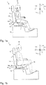
- FIG. 1a and 1b each schematic side views of a vehicle seat 1 according to the invention are shown.
- This vehicle seat 1 with longitudinal direction 1x, width direction 1y and height direction 1z has in the present case a headrest part 15, a backrest part 4, a seat part 2 and a seat support shell 3.
- the seat support shell 3 is connectable to a body 16 of a vehicle, not shown.
- Dummies D 1, D 2 shown in simplified form assume those two limits within which 90% of the sizes of all possible seat occupants lie. In other words, 5% of all possible seat occupants are smaller than the dummy D1 and another 5% of all possible seat occupants are larger than the dummy D2.
- the vehicle seat 1 according to the invention is therefore suitable for at least 90% of all possible seat occupants.
- a positive slope means that viewed in the direction of travel 1xa the rear end 5b of the vehicle seat 1 with respect to the height direction 1z is lower than the front end 5a (as in Fig. 1b shown).
- a negative inclination means that the rear end 5b of the vehicle seat 1 with respect to the height direction 1z is higher than the front end 5a.
- a slope with the value zero is shown.
- the front 5a and the rear end 5b of the seat part 2 are to be understood in particular as representing reference points which are arranged halfway up the seat part 2.
- the lower end 4b of the backrest part 4 is to be understood as a reference point arranged at half the width of the backrest part 4.
- the dummy D1 is, for example, a woman who, due to her small body size, has arranged the seat part 2 in such a way that, with regard to its depth, it is located in a rear maximum position 2 '.
- the inclination of the seat part 2 assumes a minimum position and is equal to zero in the present case. It would also be conceivable that the minimum position represents a small negative or low positive value.
- the dummy D2 is, for example, a man who, because of his tall body height, has arranged the seat part 2 so that it is in a front maximum position 2 "with respect to its depth for example, 5 ° higher than the inclination of the seat part 2 in the minimum position.
- Fig. 1a It can be seen that the rear end 5b of the seat part 2 and a rear surface 17b of the backrest part 4 in the longitudinal direction 1xa, 1xb of the seat 1 are substantially arranged on a (shown dashed lines here) first line 19a. Furthermore, in this case, the seat part 2 and the backrest part 4 are formed directly adjacent to each other; In this case, at least the lower end 4b of the backrest part 4 makes contact with the seat part 2.
- Fig. 1b It can be seen that the rear end 5b of the seat part 2 and a front surface 17a of the backrest part 4 in the longitudinal direction 1xa, 1xb of the seat 1 are substantially arranged on a second line 19b (shown here with dashed lines). Furthermore, in this case, the seat part 2 and the backrest part 4 are formed spaced from each other.
- the seat part 2 is cup-shaped on the underside, wherein by means of the adjustment of the seat part 2, the front end 5a of the seat part 2 against the arranged below the seat part 2 seat support shell 3 combined 1xa forward and 1za displaceable upwards and thus the inclination of the seat part 2 is adjustable ,
- the headrest part 15 is mechanically firmly connected to the backrest part 4. More preferably, the headrest part 15 is arranged relative to the backrest part 4 pivotable and / or height adjustable.
- the backrest part 4 is presently connected to the seat support shell 3 by means of a mechanically fixed connection, not shown, and arranged pivotably relative to the seat support shell 3, so that the inclination of the backrest part 4 is adjustable.
- the backrest part 4 may be mechanically rigidly connected to the seat support shell 3.
- an elastic connection 14 is indicated, by means of which the rear end 5b of the seat part 2 is connected to a lower end 4b of the backrest part 4.
- this elastic connection 14 is designed in the form of a stretchable fabric section or a rubber material.
- FIGS. 2a and 2b, 2c and 2d and FIGS. 2e and 2f show the uncovered seat part 2 without a cushion part or a seat part shell 18 of the seat part 2 in different positions in relation to the seat support shell 3.
- the FIGS. 2a and 2 B represent plan views that Figures 2c and 2d Side views as well as the FIGS. 2e and 2f Cross-sectional views of the arrangement of seat shell 18 and seat support shell 3. Further, by means of Fig. 2g a section of the Fig. 2e displayed.
- grooves 8 are configured, in this case a total of four in number, each two consecutively (one adjacent to the front end 5a and another adjacent to the rear end 5b) and two parallel to each other and are arranged in the longitudinal direction of the seat 1 at the same height.
- the grooves 8 have end stops, i. that a course of the grooves 8 and thus the adjustment of the seat part 2 in the longitudinal direction 1xa, 1xb of the seat 1 is limited.
- sliding blocks 9 are shown, which are arranged on the seat support shell 3 on the upper side and complementary to the grooves 8. These sliding blocks 9 can be guided in the adjustment movement of the seat part 2 relative to the seat support shell 3 as sliding elements within the grooves 8. It can clearly be seen that the position of the sliding blocks 9 relative to the grooves 8 in the comparison of Fig. 2a to Fig. 2b changes.
- these sliding blocks 9 are configured by means of three sections.
- a first section represents the connection to the seat support shell 3.
- a second section following the first section has the grooves 8 of the seat part shell 18 penetratingly arranged.
- a third section following the second section is arranged on the side of the seat part shell facing away from the seat support shell 3 and is preferably wider than the width of the grooves 8, so that a secure connection between the seat part 2 and the seat support shell 3 is ensured by positive locking.
- a manually releasable locking device 10 by means of which the position of the seat part 2 with respect to a position of the seat support shell 3 can be locked.
- This locking device 10 comprises a arranged at the front end 5a of the seat part 2 manual operating lever 11 with material recesses 12, which are designed in the present case rectangular and in which a complementary For this ausgestaltetes web element 13 can be latched.
- This web element 13 is arranged on the seat support shell 3.
- Fig. 3 In a schematic diagram, different guide geometries can be seen, by means of which the adjustment movement of the seat part 2 can be realized.
- a first point is shown, which is to represent the position of the rear end 5b of the seat part 2 in the rear maximum position 2 '.
- This is in this example shown in the longitudinal direction 1xa, 1xb of the vehicle seat 1 at a height with a second point, which should represent the position of the front end 5a of the seat part 2 in the rear maximum position 2 '.
- a third point which is to represent the position of the rear end 5b of the seat part 2 in the front maximum position 2 ", and a fourth point which is to represent the position of the front end 5a of the seat part 2 in the front maximum position 2".
- the first and third points and the second and fourth points are each connected to each other by a line representing the inclinations of the seat part 2 in the rear maximum position 2 'and in the front maximum position 2 ", respectively.
- the first and second points, and the third and fourth points are connected to each other by a line and a circular arc section.
- the lines represent the straight lines 7a, 7b and the circular arc sections the cam tracks 6a, 6b, along which the front end 5a and / or a rear end 5b of the seat part 2 relative to the seat support shell 3 by means of the adjustment of the seat part 2 are displaceable.
- distances d1 and d2 which with respect to the adjustment of the seat part 2, the first maximum displacement of the front end 5a of the seat part 2 relative to the seat support shell 3 to the front 1xa (d1) and the second maximum displacement of the front end 5a of the seat part 2 against the Seat tray 3 up 1za (d2) represent.
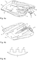
- the seat part 2 is in the Fig. 4a again from diagonally above as well as in the Fig. 4b shown obliquely below each without a cushion part, so that the unclad seat shell 18 of the seat part 2 can be seen.
- the continuously arranged grooves 8 can be seen.
- the course of the grooves 8 forms one of the according to Fig. 3 imitated variants, so that the adjusting movement of the seat part 2 takes place either on the straight lines 7a and 7b, on the cam tracks 6a and 6b, on the straight line 7a and the cam track 6b or on the straight line 7b and the cam track 6a.
- FIGS. 4a and 4b the manually releasable locking device 10, by means of which a position of the seat part 2 with respect to a position of the seat support shell 3 can be locked.
- the Fig. 4c shows a further variant according to which not only one, but a plurality of web elements 13 are arranged on the seat support shell 3. This increases the reliability of the lock.
Landscapes
- Engineering & Computer Science (AREA)
- Aviation & Aerospace Engineering (AREA)
- Transportation (AREA)
- Mechanical Engineering (AREA)
- Seats For Vehicles (AREA)
Abstract
Description
- Die Erfindung betrifft einen Fahrzeugsitz mit einem Sitzteil und einem Rückenlehnenteil gemäß dem Oberbegriff des Anspruchs 1.
- Aus dem Stand der Technik sind bereits verschiedene Ausgestaltungen für Fahrzeugsitze mit Verstelleinrichtungen für die Tiefe oder die Neigung des Sitzteils bekannt. Dabei ist unter Sitztiefe beispielsweise der Abstand zwischen einem vorderen Ende des Sitzteils und der Anlehnfläche, also der vorderen Fläche, des Rückenlehnenteils zu verstehen.
- Die Verstellmöglichkeiten dieser beiden Parameter "Sitztiefe" und "Sitzneigung" gehören zur Standardausstattung von Komfortsitzen und demzufolge zum Stand der Technik. Allerdings werden bisher die Verstellfunktionen getrennt, mithin einzeln verbaut und können auch nur einzeln angesteuert werden.
- Es ist daher Aufgabe der vorliegenden Erfindung, den Stand der Technik derart weiterzuentwickeln, so dass eine Kopplung der beiden Verstellmöglichkeiten zu einer kombinierten Verstellung realisiert wird. Dies bedeutet, dass beispielsweise mit einem Handgriff gleichzeitig mit der Verschiebung des Sitzpolsters in oder gegen die Fahrtrichtung eine Veränderung der Sitzneigung durchgeführt werden kann.
- Diese Aufgabe wird gelöst von einem Fahrzeugsitz mit einem Sitzteil und einem Rückenlehnenteil, wobei das Sitzteil unterseitig schalenförmig ausgebildet ist, und wobei mittels einer Verstellbewegung des Sitzteils gegenüber einer unterhalb des Sitzteils angeordneten Sitztragschale zumindest ein vorderes Ende des Sitzteils kombiniert nach vorne und nach oben verschiebbar und die Neigung des Sitzteils verstellbar ist.
- Bevorzugt wird bei einer Verschiebung des Sitzpolsters in Fahrtrichtung die Neigung des Sitzteils steiler, also größer. Analog dazu wird bei einer Verschiebung des Sitzpolsters gegen die Fahrtrichtung die Neigung des Sitzteils flacher.
- Mittels einer einzigen Verstellbewegung des Sitzteils sind also ein Grad einer Tiefe und ein Grad einer Neigung des Sitzteils kombiniert verstellbar. Aus dieser kombinierten Verstellung ergeben sich zahlreiche Vorteile. So kann der Sitzinsasse mit nur einem Griff bzw. einer einzigen Betätigung eines Betätigungselements beide Parameter gleichzeitig verstellen. Da diese Parameter hinsichtlich ihrer Änderung bevorzugt aufeinander bzw. auf eine möglichst komfortable Sitzteileinstellung ausgerichtet sind, kann, wie später noch anhand der Figuren erläutert, für einen großen Anteil an sich hinsichtlich ihrer Körpergröße unterscheidenden Sitzinsassen jeweils eine ideale Komforteinstellung realisiert werden.
- Weiterhin gilt natürlich, dass die Kosten für die Herstellung und die Montage des Fahrzeugsitzes sinken, da die integrierte Technik vereinfacht ist.
- Bevorzugt sind die Abmessungen des Sitzteils mittels der Verstellbewegung nicht veränderbar; mit anderen Worten ist also insbesondere ein Abstand zwischen dem vorderen Ende und dem hinteren Ende des Sitzteils unabhängig von der Position des Sitzteils stets gleichbleibend ausgebildet.
- Die Unterschenkellänge ist dabei anzunehmen als Abstand des Fahrzeugbodens bzw. einer Abstellfläche für die Schuhe des Sitzinsassen von einer Position des Knies des Sitzinsassen, welche wiederum oberhalb der Sitzfläche des Sitzteils angeordnet ist. Die Sitztiefe ist beispielsweise natürlich von der Oberschenkellänge des Sitzinsassen abhängig und entspricht dieser bevorzugt. Dabei wird die Oberschenkellänge im sitzenden Zustand des Sitzinsassen als Abstand zwischen Gesäß und Kniekehle vermessen.
- Entsprechend einer Vermessung möglicher Sitzinsassen gemäß der Norm DIN CEN ISO/TR 7250-2 weist dabei im Durchschnitt ein erster Sitzinsasse, für welchen gilt, dass 5% aller möglichen Sitzinsassen kleiner sind als er, eine Unterschenkellänge von 405 mm und eine Oberschenkellänge von 435 mm auf. Ferner weist im Durchschnitt ein zweiter Mensch, für welchen gilt, dass 5% aller möglichen Sitzinsassen größer sind als er, eine Unterschenkellänge von 520 mm und eine Oberschenkellänge von 540 mm auf.
- Dabei weist ein Wert einer Unterschenkellänge des Sitzinsassen zu einem Wert der Sitztiefe einen statistischen Korrelationswert von 0,64 auf. Hierbei beschreibt der Korrelationswert, welcher zwischen 0 und 1 (bzw. -1) liegen kann, das Maß der Abhängigkeit zweier Größen zueinander; so deutet ein Wert nahe 1 (bzw. nahe -1) auf eine sehr hohe Korrelation der beiden Größen hin, was entsprechend bei der Sitzkonstruktion berücksichtigt werden sollte.
- Weiter bevorzugt ist dabei der Grad der Neigung des Sitzteils in Abhängigkeit des Grads der Sitztiefe so ausgestaltet, dass in einer Idealposition ein Verhältnis der Unterschenkellänge des Sitzinsassen zur Oberschenkellänge (bevorzugt entsprechend der Sitztiefe) des Sitzinsassen einen Wert aus einem Bereich von 0,93 bis 0,97 aufweist.
- Eine bevorzugte Ausführungsform der Erfindung sieht vor, dass mittels der Verstellbewegung des Sitzteils das vordere Ende und/ oder ein hinteres Ende des Sitzteils gegenüber der Sitztragschale entlang einer Kurvenbahn und/ oder entlang einer Geraden nach vorne verschiebbar ist.
- Wenn das vordere Ende und das hintere Ende als Referenzpunkte dargestellt werden, dann sind diese Bewegungslinien (Kurvenbahn und/ oder Gerade) jeweils als Funktionsgraph der Position der Referenzpunkte zu sehen. Mit anderen Worten erfährt mittels der Verstellbewegung des Sitzteils das vordere Ende des Sitzteils entweder eine geradlinige oder eine bogenförmige Bewegung. Gleiches gilt für das hintere Ende. So ist für maximale Flexibilität und bestmögliche Ausnutzung des Bauraums gesorgt.
- Eine bevorzugte Variante sieht vor, dass das hintere Ende entlang einer Geraden und das vordere Ende entlang einer Kurvenbahn verschiebbar ist. Eine weitere bevorzugte Variante sieht vor, dass sowohl das hintere Ende als auch das vordere Ende jeweils entlang einer Kurvenbahn verschiebbar sind.
- Weiterhin ist es bevorzugt, dass das Sitzteil unterseitig Nuten aufweist und auf der Sitztragschale oberseitig komplementär dazu ausgebildete Nutensteine angeordnet sind, welche bei der Verstellbewegung des Sitzteils gegenüber der Sitztragschale als Gleitelemente innerhalb der Nuten führbar sind. Diese Ausgestaltung sorgt für eine mechanisch sichere und reproduzierbare Führung des Sitzteils gegenüber der Sitztragschale.
- Außerdem kann die Form und der Verlauf der Nuten genutzt werden, um die Veränderung der Sitztiefe und/ oder der Sitzneigung gezielt zu beeinflussen. So ist es denkbar, dass die Nuten in Längsrichtung und/ oder Höhenrichtung des Fahrzeugsitzes verlaufend angeordnet sind; weiter bevorzugt ist ein Verlauf der Nuten ohne Änderungen in Breitenrichtung und damit stets parallel zur Breitenrichtung des Fahrzeugsitzes ausgestaltet.
- Weiter ist es denkbar, dass in Längsrichtung des Fahrzeugsitzes mindestens eine Nut, bevorzugt zwei Nuten aufeinanderfolgend angeordnet sind. Weiter ist es denkbar, dass in Breitenrichtung des Fahrzeugsitzes mindestens eine Nut, bevorzugt zwei Nuten nebeneinander verlaufend angeordnet sind.
- Je nach gewünschter Verstellbewegung können diese Nuten bezogen auf die Längsrichtung des Fahrzeugsitzes einen geradlinigen oder bogenförmigen Verlauf aufweisen.
- Denkbar ist auch, dass statt der erläuterten Anordnung die Nuten auf der Sitztragschale angeordnet und die Nutensteine mit dem Sitzteil fest verbunden sind. Des Weiteren können in beiden Varianten statt der Nutensteine längliche Erhebungen verwendet werden, weiter bevorzugt sind diese beispielsweise im Querschnitt im Wesentlichen dreiecksförmig.
- Aus der Norm DIN EN ISO 5353 ist die Ermittlung des sogenannten Sitz-Index-Punkts (SIP) für einen Sitzinsassen mit 75 kg Körpergewicht bekannt. Dieser repräsentiert den Schnittpunkt zwischen den theoretischen Achsen des menschlichen Oberkörpers und des menschlichen Oberschenkels auf der senkrechten Ebene durch die Sitzmittellinie. Demnach wird der Hüftpunkt (H-Punkt) eines Menschenmodells mit dem SIP in Übereinstimmung gebracht und simuliert die Lage des Beckens im gewichtsbelasteten Sitz. Gemäß der vorliegenden Erfindung und deren kompakte Bauweise ist es möglich, den SIP relativ tief anzuordnen, was zum Komfort des Sitzinsassen beiträgt.
- Weiterhin gilt, dass beim erfindungsgemäßen Sitz die Führungselemente zur Führung der Verstellbewegung des Sitzteils ausschließlich zwischen Sitzteil und Sitzschalenelement angeordnet sind, insbesondere also unterhalb des Sitzteils und oberhalb des Sitzschalenelements. Dahingegen ist insbesondere der Raum seitlich neben dem Sitzteil und neben der Sitztragschale frei von zur erfindungsgemäßen Verstellbewegung des Sitzteils ausgestalteten Führungselementen.
- Um den Komfort des Sitzinsassen weiter zu erhöhen, hat es sich in der Praxis bewährt, wenn eine Position des Sitzteils in Bezug auf eine Position der Sitztragschale mittels einer manuell lösbaren Arretiervorrichtung arretierbar ist, wobei die Arretiervorrichtung einen am Sitzteil angeordneten manuellen Betätigungshebel mit Materialausnehmungen umfasst, in welchen mindestens ein komplementär dazu ausgestaltetes, an der Sitztragschale angeordnetes Stegelement einrastbar ist. Dieser Betätigungshebel kann baulich einfach als Lochblech ausgestaltet sein.
- Hierbei durchdringen das mindestens eine oder mehrere einzelne Stegelemente die entsprechenden Materialausnehmungen, wodurch der Betätigungshebel, welcher bevorzugt am vorderen Ende des Sitzteils, weiter bevorzugt an einer Unterseite des Sitzteils und noch weiter bevorzugt zumindest teilweise zwischen den unterseitig angeordneten Nuten des Sitzteils angeordnet ist und damit das Sitzteil an der Sitztragschale festgelegt ist. In diesem Zustand ist die Position des Sitzteils gegenüber der Sitztragschale arretiert.
- Wird der Betätigungshebel beispielsweise durch einen Griff des Sitzinsassen nach oben ausgelenkt, so rücken die Stegelemente auf der Sitztragschale aus den Materialausnehmungen auf dem Betätigungshebel aus, wodurch die Arretierung der Position des Sitzteils gegenüber der Sitztragschale aufgehoben ist. In diesem Zustand lässt sich also die Verstellbewegung des Sitzteils gegenüber der Sitztragschale durchführen.
- Aus der Praxis hat es sich insbesondere in Bezug auf die Größenverteilung der Sitzinsassen bewährt, wenn hinsichtlich der Verstellbewegung des Sitzteils ein erster maximaler Verstellweg des vorderen Endes des Sitzteils gegenüber der Sitztragschale nach vorne einen Wert aus einem Bereich von 40 mm bis 80 mm, bevorzugt von 60 mm aufweist, und/ oder ein zweiter maximaler Verstellweg des vorderen Endes des Sitzteils gegenüber der Sitztragschale nach oben einen Wert aus einem Bereich von 10 mm bis 30 mm, bevorzugt von 20 mm aufweist. Diese Abmessungen werden auch den Platzverhältnissen innerhalb eines kleinen Fahrzeugs gerecht.
- Weiterhin hat es sich bewährt, wenn hinsichtlich der Verstellbewegung des Sitzteils die Neigung des Sitzteils in einer hinteren Maximalposition des Sitzteils einen Wert aufweist, welcher einen Unterschied von 2° bis 10°, bevorzugt von 5° zu einem Wert der Neigung des Sitzteils in einer vorderen Maximalposition des Sitzteils aufweist.
- Wenn das Sitzteil sich in der hinteren Maximalposition befindet, ist es bevorzugt, wenn das hintere Ende des Sitzteils und eine hintere Fläche des Rückenlehnenteils in Längsrichtung des Sitzes betrachtet im Wesentlichen auf einer Linie angeordnet sind. Weiterhin gilt, dass in diesem Fall das Sitzteil und das Rückenlehnenteil bevorzugt zueinander unmittelbar angrenzend ausgebildet sind.
- Wenn das Sitzteil sich in der vorderen Maximalposition befindet, ist es bevorzugt, wenn das hintere Ende des Sitzteils und eine vordere Fläche des Rückenlehnenteils in Längsrichtung des Sitzes betrachtet im Wesentlichen auf einer Linie angeordnet sind. Weiterhin gilt, dass in diesem Fall das Sitzteil und das Rückenlehnenteil bevorzugt zueinander beabstandet ausgebildet sind.
- Diese vorstehenden bevorzugten Anordnungen gelten insbesondere in dem Fall, wenn das Rückenlehnenteil im Wesentlichen senkrecht, also hinsichtlich seiner Längserstreckung im Wesentlichen parallel zur Höhenrichtung des Sitzes angeordnet ist.
- Um dem Benutzer vor allem in der vorderen Maximalstellung trotz Abstand zwischen Sitzteil und Rückenlehnenteil einen hohen Komfort zu garantieren, hat es sich als vorteilhaft herausgestellt, wenn das hintere Ende des Sitzteils mit einem unteren Ende des Rückenlehnenteils mittels einer elastischen Verbindung verbunden ist. Diese elastische Verbindung ist bevorzugt über die gesamte Breite des Sitzteils ausgestaltet und kann beispielsweise mittels eines Gummibandes ausgestaltet sein, welches das Gesäß des Sitzinsassen abstützt. Es gilt allerdings, dass die Verstellbewegung des Sitzteils vom Rückenlehnenteil entkoppelt ist. Alternativ zu einer elastischen Verbindung kann es vorteilhaft sein, wenn das Sitzteil vom Rückenlehnenteil beabstandet und zu diesem verbindungselementfrei angeordnet ist.
- Weiter ist es bevorzugt, dass das Rückenlehnenteil mit der Sitztragschale verbunden und/ oder gegenüber der Sitztragschale unabhängig von der Verstellbewegung des Sitzteils verschwenkbar ist. Auch dies sorgt für einen erhöhten Komfort für den Sitzinsassen. Außerdem kann die Mechanik der Verschwenkung des Rückenlehnenteils vereinfacht werden, wenn es mit einem in diesem Fall bevorzugt starr zu den restlichen Komponenten des Fahrzeugsitzes angeordneten Element wie der Sitztragschale verbunden ist.
- Vorteilhafte Ausführungsformen ergeben sich aus den Unteransprüchen.
- Vorteile und Zweckmäßigkeiten sind der nachfolgenden Beschreibung in Verbindung mit der Zeichnung zu entnehmen.
- Es zeigen:
- Fig. 1a-1c
- in schematischen Seitenansichten verschiedene Positionen des Sitzteils des erfindungsgemäßen Fahrzeugsitzes;
- Fig. 2a-2g
- verschiedene Ansichten und Verstellpositionen des Sitzteils und der Sitzschale;
- Fig. 3a, 3b
- in Prinzipskizzen verschiedene Verstellbewegungen des Sitzteils gegenüber der Sitztragschale anhand dargestellter Kurvenbahnen und Geraden;
- Fig. 4a-4c
- verschiedene Ansichten des Sitzteils und der Sitzschale.
- In
Fig. 1a und 1b sind jeweils schematische Seitenansichten eines erfindungsgemäßen Fahrzeugsitzes 1 dargestellt. Dieser Fahrzeugsitz 1 mit Längsrichtung 1x, Breitenrichtung 1y und Höhenrichtung 1z weist vorliegend ein Kopfstützenteil 15, ein Rückenlehnenteil 4, ein Sitzteil 2 sowie eine Sitztragschale 3 auf. Beispielsweise ist die Sitztragschale 3 mit einer Karosserie 16 eines nicht dargestellten Fahrzeugs verbindbar. - Auf den Fahrzeugsitzen 1 gemäß
Fig. 1a und Fig. 1b dargestellte Dummies D1, D2 markieren vereinfacht angenommen jene beiden Grenzen, innerhalb der 90% der Größen aller möglichen Sitzinsassen liegen. Mit anderen Worten sind 5% aller möglichen Sitzinsassen kleiner als der Dummy D1 und weitere 5% aller möglichen Sitzinsassen größer als der Dummy D2. Der erfindungsgemäße Fahrzeugsitz 1 ist also zumindest für 90% aller möglichen Sitzinsassen geeignet. - Die Neigung des Sitzes 1 sei im Folgenden so definiert, dass eine positive Neigung bedeutet, dass in Fahrtrichtung 1xa betrachtet das hintere Ende 5b des Fahrzeugsitzes 1 in Bezug auf die Höhenrichtung 1z tiefer liegt als das vordere Ende 5a (wie in
Fig. 1b dargestellt). Umgekehrt bedeutet eine negative Neigung, dass das hintere Ende 5b des Fahrzeugsitzes 1 in Bezug auf die Höhenrichtung 1z höher liegt als das vordere Ende 5a. InFig. 1a ist dagegen eine Neigung mit dem Wert Null dargestellt. - Das vordere 5a und das hintere Ende 5b des Sitzteils 2 sind insbesondere so zu verstehen, dass diese Referenzpunkte darstellen, welche auf halber Höhe des Sitzteils 2 angeordnet sind. Analog dazu ist das untere Ende 4b des Rückenlehnenteils 4 als ein auf halber Breite des Rückenlehnenteils 4 angeordneter Referenzpunkt zu verstehen.
- Der Dummy D1 ist beispielsweise eine Frau, die aufgrund ihrer geringen Körpergröße das Sitzteil 2 so angeordnet hat, dass es sich hinsichtlich seiner Tiefe in einer hinteren Maximalposition 2' befindet. Damit nimmt vorliegend die Neigung des Sitzteils 2 eine Minimalposition ein und ist vorliegend gleich Null. Denkbar wäre aber auch, dass die Minimalposition einen geringen negativen oder geringen positiven Wert darstellt.
- Dahingegen ist der Dummy D2 beispielsweise ein Mann, der aufgrund seiner hoch gewachsenen Körpergröße das Sitzteil 2 so angeordnet hat, dass es sich hinsichtlich seiner Tiefe in einer vorderen Maximalposition 2" befindet. Damit nimmt vorliegend die Neigung des Sitzteils 2 eine Maximalposition ein und ist vorliegend beispielsweise um 5° höher als die Neigung des Sitzteils 2 in Minimalposition.
- Gemäß
Fig. 1a ist zu sehen, dass das hintere Ende 5b des Sitzteils 2 und eine hintere Fläche 17b des Rückenlehnenteils 4 in Längsrichtung 1xa, 1xb des Sitzes 1 betrachtet im Wesentlichen auf einer (hier gestrichelt eingezeichneten) ersten Linie 19a angeordnet sind. Weiterhin gilt, dass in diesem Fall das Sitzteil 2 und das Rückenlehnenteil 4 zueinander unmittelbar angrenzend ausgebildet sind; in diesem Fall bildet zumindest das untere Ende 4b des Rückenlehnenteils 4 Kontakt zum Sitzteil 2 aus. - Gemäß
Fig. 1b ist zu sehen, dass das hintere Ende 5b des Sitzteils 2 und eine vordere Fläche 17a des Rückenlehnenteils 4 in Längsrichtung 1xa, 1xb des Sitzes 1 betrachtet im Wesentlichen auf einer (hier gestrichelt eingezeichneten) zweiten Linie 19b angeordnet sind. Weiterhin gilt, dass in diesem Fall das Sitzteil 2 und das Rückenlehnenteil 4 zueinander beabstandet ausgebildet sind. - Diese vorstehenden bevorzugten Anordnungen gelten für den gemäß den
Figuren 1a und1 b gezeigten Fall, wenn das Rückenlehnenteil 4 im Wesentlichen senkrecht, also hinsichtlich seiner Längserstreckung parallel zur Höhenrichtung 1z des Sitzes 1 angeordnet ist. - Vorliegend ist das Sitzteil 2 unterseitig schalenförmig ausgebildet, wobei mittels der Verstellbewegung des Sitzteils 2 das vordere Ende 5a des Sitzteils 2 gegenüber der unterhalb des Sitzteils 2 angeordneten Sitztragschale 3 kombiniert nach vorne 1xa und nach oben 1za verschiebbar und somit die Neigung des Sitzteils 2 verstellbar ist.
- Bevorzugt ist das Kopfstützenteil 15 mechanisch fest mit dem Rückenlehnenteil 4 verbunden. Weiter bevorzugt ist das Kopfstützenteil 15 gegenüber dem Rückenlehnenteil 4 schwenkbar und/ oder höhenverstellbar angeordnet.
- Das Rückenlehnenteil 4 ist vorliegend mit der Sitztragschale 3 mittels einer nicht gezeigten mechanisch festen Verbindung verbunden und gegenüber der Sitztragschale 3 verschwenkbar angeordnet, so dass die Neigung des Rückenlehnenteils 4 einstellbar ist. Alternativ kann das Rückenlehnenteil 4 mit der Sitztragschale 3 mechanisch starr verbunden sein.
- In
Fig. 1b ist eine elastische Verbindung 14 angedeutet, mittels welcher das hintere Ende 5b des Sitzteils 2 mit einem unteren Ende 4b des Rückenlehnenteils 4 verbunden ist. Beispielsweise ist diese elastische Verbindung 14 in Form eines dehnbaren Stoffabschnitts oder eines Gummiwerkstoffs ausgestaltet. - Wie insbesondere aus einem Vergleich der
Figuren 1a und 1b zu sehen ist, ist die Verstellbewegung des Sitzteils 2 vom Rückenlehnenteil 4 entkoppelt. Mit anderen Worten werden weder die Position noch die Neigung noch eine Wölbung des Rückenlehnenteils 4 verändert, wenn die Verstellbewegung des Sitzteils 2 stattfindet. Umgekehrt gilt natürlich auch, dass eine Verschwenkbewegung des Rückenlehnenteils 4 von einer Verstellbewegung des Sitzteils 2 entkoppelt ist, so dass auch die Position des Sitzteils 2 nicht verändert wird, wenn die Rückenlehnenteil 4 verschwenkt wird. - In
Fig. 1c sind zum besseren Vergleich beide Dummies D1, D2 übereinander gelagert dargestellt. - Gemäß den Ansichten in den
Fig. 2a und2b, 2c und 2d sowie 2e und 2f ist das unverkleidete Sitzteil 2 ohne ein Polsterteil bzw. eine Sitzteilschale 18 des Sitzteils 2 in verschiedenen Positionen gegenüber der Sitztragschale 3 dargestellt. Dabei zeigen dieFiguren 2a ,2c und2e die hintere Maximalposition 2'und dieFiguren 2b, 2d und2f die vordere Maximalposition 2" des Sitzteils 2. DieFiguren 2a und2b repräsentieren Draufsichten, dieFiguren 2c und 2d Seitenansichten sowie dieFiguren 2e und 2f Querschnittsansichten der Anordnung aus Sitzteilschale 18 und Sitztragschale 3. Ferner ist mittels derFig. 2g ein Ausschnitt derFig. 2e abgebildet. - In dem Sitzteil 2 bzw. in der Sitzteilschale 18 sind Nuten 8 ausgestaltet, vorliegend insgesamt vier an der Zahl, wobei jeweils zwei hintereinander (eine davon benachbart zum vorderen Ende 5a und eine weitere davon benachbart zum hinteren Ende 5b) und jeweils zwei parallel zueinander und in Längsrichtung des Sitzes 1 auf gleicher Höhe angeordnet sind. Die Nuten 8 weisen Endanschläge auf, d.h. dass ein Verlauf der Nuten 8 und damit der Verstellweg des Sitzteils 2 in Längsrichtung 1xa, 1xb des Sitzes 1 begrenzt ist.
- Gleichzeitig sind Nutensteine 9 abgebildet, welche auf der Sitztragschale 3 oberseitig und komplementär zu den Nuten 8 angeordnet sind. Diese Nutensteine 9 sind bei der Verstellbewegung des Sitzteils 2 gegenüber der Sitztragschale 3 als Gleitelemente innerhalb der Nuten 8 führbar. Deutlich ist zu sehen, dass sich die Position der Nutensteine 9 relativ zu den Nuten 8 im Vergleich von
Fig. 2a zuFig. 2b ändert. - Bevorzugt sind diese Nutensteine 9 mittels dreier Abschnitte ausgestaltet. Ein erster Abschnitt stellt die Verbindung zur Sitztragschale 3 dar. Ein zweiter, auf den ersten Abschnitt folgender Abschnitt ist die Nuten 8 der Sitzteilschale 18 durchdringend angeordnet. Ein dritter, auf den zweiten Abschnitt folgender Abschnitt ist auf der der Sitztragschale 3 abgewandten Seite der Sitzteilschale angeordnet und bevorzugt breiter als die Breite der Nuten 8 ausgestaltet, so dass per Formschluss eine sichere Verbindung zwischen Sitzteil 2 und Sitztragschale 3 gewährleistet ist.
- Ebenfalls abgebildet ist insbesondere gemäß den
Figuren 2e und 2f eine manuell lösbare Arretiervorrichtung 10, mittels welcher die Position des Sitzteils 2 in Bezug auf eine Position der Sitztragschale 3 arretierbar ist. Diese Arretiervorrichtung 10 umfasst einen am vorderen Ende 5a des Sitzteils 2 angeordneten manuellen Betätigungshebel 11 mit Materialausnehmungen 12, welche vorliegend rechteckförmig ausgestaltet sind und in welchen ein komplementär dazu ausgestaltetes Stegelement 13 einrastbar ist. Dieses Stegelement 13 ist an der Sitztragschale 3 angeordnet. - Das Zusammenwirken von Stegelement 13 und Materialausnehmungen 12 ist gemäß
Fig. 2g vergrößert abgebildet. Deutlich ist, dass das Stegelement 13 in derFig. 2e in einer näher dem Betätigungshebel 11 zugewandten Materialausnehmung 12 einrastet als in derFig. 2f . - Gemäß
Fig. 3 sind in einer Prinzipskizze verschiedene Führungsgeometrien zu sehen, mittels welcher die Verstellbewegung des Sitzteils 2 realisiert werden kann. Dazu ist ein erster Punkt abgebildet, welcher die Position des hinteren Endes 5b des Sitzteils 2 in der hinteren Maximalstellung 2' darstellen soll. Dieser liegt in diesem gezeigten Beispiel in Längsrichtung 1xa, 1xb des Fahrzeugsitzes 1 auf einer Höhe mit einem zweiten Punkt, welcher die Position des vorderen Endes 5a des Sitzteils 2 in der hinteren Maximalstellung 2' darstellen soll. - Ebenfalls abgebildet sind ein dritter Punkt, welcher die Position des hinteren Endes 5b des Sitzteils 2 in der vorderen Maximalstellung 2" darstellen soll, und ein vierter Punkt, welcher die Position des vorderen Endes 5a des Sitzteils 2 in der vorderen Maximalstellung 2" darstellen soll.
- Der erste und der dritte Punkt sowie der zweite und der vierte Punkt sind jeweils miteinander durch eine Linie verbunden, welche die Neigungen des Sitzteils 2 in der hinteren Maximalstellung 2' bzw. in der vorderen Maximalstellung 2" repräsentieren sollen.
- Der erste und der zweite Punkt sowie der dritte und der vierte Punkt sind jeweils miteinander durch eine Linie und einen Kreisbogenabschnitt verbunden. Dabei repräsentieren die Linien die Geraden 7a, 7b und die Kreisbogenabschnitte die Kurvenbahnen 6a, 6b, entlang welchen das vordere Ende 5a und/ oder ein hinteres Ende 5b des Sitzteils 2 gegenüber der Sitztragschale 3 mittels der Verstellbewegung des Sitzteils 2 verschiebbar sind.
- Ebenfalls eingezeichnet sind Distanzen d1 und d2, welche hinsichtlich der Verstellbewegung des Sitzteils 2 den ersten maximalen Verstellweg des vorderen Endes 5a des Sitzteils 2 gegenüber der Sitztragschale 3 nach vorne 1xa (d1) sowie den zweiten maximalen Verstellweg des vorderen Endes 5a des Sitzteils 2 gegenüber der Sitztragschale 3 nach oben 1za (d2) darstellen.
- Ferner ist ein Winkel α zwischen der Längserstreckung des Sitzteils 2 in der hinteren Maximalstellung 2' und der Längserstreckung des Sitzteils 2 in der vorderen Maximalstellung 2" zu sehen, welcher die maximale Veränderung des Grades der Neigung des Sitzteils 2 veranschaulicht.
- Das Sitzteil 2 ist in der
Fig. 4a nochmals von schräg oben sowie in derFig. 4b von schräg unten jeweils ohne ein Polsterteil dargestellt, so dass die unverkleidete Sitzteilschale 18 des Sitzteils 2 zu sehen ist. In dieser Sitzteilschale 18 des Sitzteils 2 sind die durchgehend angeordneten Nuten 8 zu sehen. - Bevorzugt bildet der Verlauf der Nuten 8 eine der gemäß
Fig. 3 abgebildeten Varianten ab, so dass die Verstellbewegung des Sitzteils 2 entweder auf den Geraden 7a und 7b, auf den Kurvenbahnen 6a und 6b, auf der Gerade 7a und der Kurvenbahn 6b oder auf der Gerade 7b und der Kurvenbahn 6a stattfindet. - Ebenfalls abgebildet ist gemäß den
Figuren 4a und 4b die manuell lösbare Arretiervorrichtung 10, mittels welcher eine Position des Sitzteils 2 in Bezug auf eine Position der Sitztragschale 3 arretierbar ist. DieFig. 4c zeigt hierbei eine weitere Variante, gemäß der nicht nur ein, sondern mehrere Stegelemente 13 an der Sitztragschale 3 angeordnet sind. Dies erhöht die Zuverlässigkeit der Arretierung. - Sämtliche in den Anmeldungsunterlagen offenbarten Merkmale werden als erfindungswesentlich beansprucht, sofern sie einzeln oder in Kombination gegenüber dem Stand der Technik neu sind.
-
- 1
- Fahrzeugsitz
- 1x
- Längsrichtung
- 1xa
- Richtung nach vorne, Fahrtrichtung
- 1xb
- Richtung nach hinten
- 1y
- Breitenrichtung
- 1z
- Höhenrichtung
- 1za
- Richtung nach oben
- 1zb
- Richtung nach unten
- 2
- Sitzteil
- 2', 2"
- Maximalposition
- 3
- Sitztragschale
- 4
- Rückenlehnenteil
- 4b,5a,5b
- Ende
- 6a, 6b
- Kurvenbahn
- 7a, 7b
- Gerade
- 8
- Nut
- 9
- Nutenstein
- 10
- Arretiervorrichtung
- 11
- Betätigungshebel
- 12
- Materialausnehmung
- 13
- Stegelement
- 14
- elastische Verbindung
- 15
- Kopfstützenteil
- 16
- Karosserie
- 17a, 17b
- Fläche
- 18
- Sitzteilschale
- 19a, 19b
- Linie
- d1,d2
- Distanz
- D1, D2
- Dummy
- α
- Winkel
Claims (8)
- Fahrzeugsitz (1) mit einem Sitzteil (2) und einem Rückenlehnenteil (4),
dadurch gekennzeichnet, dass
das Sitzteil (2) unterseitig schalenförmig ausgebildet ist, wobei mittels einer Verstellbewegung des Sitzteils (2) gegenüber einer unterhalb des Sitzteils (2) angeordneten Sitztragschale (3) zumindest ein vorderes Ende (5a) des Sitzteils (2) kombiniert nach vorne (1xa) und nach oben (1za) verschiebbar und die Neigung des Sitzteils (2) verstellbar ist. - Fahrzeugsitz (1) nach Anspruch 1,
dadurch gekennzeichnet, dass
mittels der Verstellbewegung des Sitzteils (2) das vordere Ende (5a) und/ oder ein hinteres Ende (5b) des Sitzteils (2) gegenüber der Sitztragschale (3) entlang einer Kurvenbahn (6a, 6b) und/ oder entlang einer Geraden (7a, 7b) nach vorne (1xa) verschiebbar ist. - Fahrzeugsitz (1) nach Anspruch 1 oder 2,
dadurch gekennzeichnet, dass
das Sitzteil (2) unterseitig Nuten (8) aufweist und auf der Sitztragschale (3) oberseitig komplementär dazu ausgebildete Nutensteine (9) angeordnet sind, welche bei der Verstellbewegung des Sitzteils (2) gegenüber der Sitztragschale (3) als Gleitelemente innerhalb der Nuten (8) führbar sind. - Fahrzeugsitz (1) nach einem der vorhergehenden Ansprüche,
dadurch gekennzeichnet, dass
eine Position des Sitzteils (2) in Bezug auf eine Position der Sitztragschale (3) mittels einer manuell lösbaren Arretiervorrichtung (10) arretierbar ist, wobei die Arretiervorrichtung (10) einen am Sitzteil (2) angeordneten manuellen Betätigungshebel (11) mit Materialausnehmungen (12) umfasst, in welchen mindestens ein komplementär dazu ausgestaltetes, an der Sitztragschale (3) angeordnetes Stegelement (13) einrastbar ist. - Fahrzeugsitz (1) nach einem der vorhergehenden Ansprüche,
dadurch gekennzeichnet, dass
hinsichtlich der Verstellbewegung des Sitzteils (2) ein erster maximaler Verstellweg des vorderen Endes (5a) des Sitzteils (2) gegenüber der Sitztragschale (3) nach vorne (1xa) einen Wert aus einem Bereich von 40 mm bis 80 mm, bevorzugt von 60 mm aufweist, und/ oder ein zweiter maximaler Verstellweg des vorderen Endes (5a) des Sitzteils (2) gegenüber der Sitztragschale (3) nach oben (1za) einen Wert aus einem Bereich von 10 mm bis 30 mm, bevorzugt von 20 mm aufweist. - Fahrzeugsitz (1) nach einem der vorhergehenden Ansprüche,
dadurch gekennzeichnet, dass
hinsichtlich der Verstellbewegung des Sitzteils (2) die Neigung des Sitzteils (2) in einer hinteren Maximalposition des Sitzteils (2) einen Wert aufweist, welcher einen Unterschied von 2° bis 10°, bevorzugt von 5° zu einem Wert der Neigung des Sitzteils (2) in einer vorderen Maximalposition des Sitzteils aufweist. - Fahrzeugsitz (1) nach einem der vorhergehenden Ansprüche,
dadurch gekennzeichnet, dass
das hintere Ende (5b) des Sitzteils (2) mit einem unteren Ende (4b) des Rückenlehnenteils (4) mittels einer elastischen Verbindung (14) verbunden ist, wobei die Verstellbewegung des Sitzteils (2) vom Rückenlehnenteil (4) entkoppelt ist. - Fahrzeugsitz (1) nach einem der vorhergehenden Ansprüche,
dadurch gekennzeichnet, dass
das Rückenlehnenteil (4) mit der Sitztragschale (3) verbunden und/ oder gegenüber der Sitztragschale (3) unabhängig von der Verstellbewegung des Sitzteils (2) verschwenkbar ist.
Applications Claiming Priority (1)
| Application Number | Priority Date | Filing Date | Title |
|---|---|---|---|
| DE102016110404.3A DE102016110404A1 (de) | 2016-06-06 | 2016-06-06 | Fahrzeugsitz mit kombinierten Verstellmöglichkeiten |
Publications (2)
| Publication Number | Publication Date |
|---|---|
| EP3254887A1 true EP3254887A1 (de) | 2017-12-13 |
| EP3254887B1 EP3254887B1 (de) | 2020-04-15 |
Family
ID=58772400
Family Applications (1)
| Application Number | Title | Priority Date | Filing Date |
|---|---|---|---|
| EP17172179.8A Active EP3254887B1 (de) | 2016-06-06 | 2017-05-22 | Fahrzeugsitz mit kombinierten verstellmöglichkeiten |
Country Status (4)
| Country | Link |
|---|---|
| US (1) | US10583754B2 (de) |
| EP (1) | EP3254887B1 (de) |
| CN (1) | CN107458280A (de) |
| DE (1) | DE102016110404A1 (de) |
Families Citing this family (4)
| Publication number | Priority date | Publication date | Assignee | Title |
|---|---|---|---|---|
| US10981472B2 (en) * | 2019-01-31 | 2021-04-20 | Brose Fahrzeugteile Gmbh & Co. Kommanditgesellschaft, Coburg | Adjusting device for a vehicle seat |
| DE102019129174B4 (de) * | 2019-10-29 | 2024-10-10 | Grammer Aktiengesellschaft | Fahrzeugsitz |
| DE102021116551A1 (de) | 2021-06-25 | 2022-12-29 | Grammer Aktiengesellschaft | Fahrzeugsitz mit Sitztiefenverstellung |
| DE102022131302B4 (de) * | 2022-11-25 | 2024-12-12 | Grammer Aktiengesellschaft | Fahrzeugsitz und Verfahren zur werkzeuglosen Montage des Fahrzeugsitzes |
Citations (7)
| Publication number | Priority date | Publication date | Assignee | Title |
|---|---|---|---|---|
| WO1992007735A1 (en) * | 1990-10-29 | 1992-05-14 | Hector Serber | Seat assembly and method |
| DE9421432U1 (de) * | 1993-02-04 | 1996-01-11 | Osann Design-, Entwicklungs- und Produktionsgesellschaft mbH, Kindersicherheitssysteme, 78244 Gottmadingen | Kindersicherheitssitz |
| WO2000021787A1 (de) * | 1998-10-14 | 2000-04-20 | Grammer Ag | Sitz |
| JP2003320880A (ja) * | 2002-04-30 | 2003-11-11 | Toyota Auto Body Co Ltd | 車両用シート |
| US20060103211A1 (en) * | 2004-05-24 | 2006-05-18 | Pascal Garrido | Seat assembly with inner seat back movable with a seat cushion |
| US20120318949A1 (en) * | 2008-03-05 | 2012-12-20 | Kenneth Braun | Low Profile Seat Position Adjustment System |
| US20130257113A1 (en) * | 2010-12-17 | 2013-10-03 | Kurt A. Seibold | Second Row Vehicle Seat |
Family Cites Families (26)
| Publication number | Priority date | Publication date | Assignee | Title |
|---|---|---|---|---|
| JPS62110038U (de) * | 1985-12-28 | 1987-07-14 | ||
| FR2604131B1 (fr) | 1986-09-19 | 1990-02-02 | Cousin Cie Ets A & M Freres | Glissieres courbes commandees |
| DE3769316D1 (de) * | 1987-08-14 | 1991-05-16 | Grammer Ag | Sitz, insbesondere arbeitssitz, bspw. buerostuhl oder fahrersitz. |
| IT213923Z2 (it) * | 1988-03-07 | 1990-03-01 | Como | Seggiolino ad inclinazione regolabile per il trasporto di bambini su autovetture. |
| US4936629A (en) | 1988-10-07 | 1990-06-26 | Rock-A-Bye Restraint Company, Inc. | Swiveling infant car seat |
| JPH0614616Y2 (ja) * | 1989-04-27 | 1994-04-20 | 池田物産株式会社 | 車両用シート |
| DE4003776C2 (de) * | 1990-02-08 | 2000-06-21 | Lear Corp | Fahrzeugsitz |
| DE4224458A1 (de) * | 1992-07-24 | 1994-01-27 | Brose Fahrzeugteile | Sitzkissenverstellung f}r Fahrzeugsitze |
| US5782536A (en) * | 1995-02-17 | 1998-07-21 | Steelcase Inc. | Modular chair construction and method of assembly |
| FR2734522B1 (fr) * | 1995-05-23 | 1997-07-25 | Faure Bertrand Equipements Sa | Siege de vehicule a longueur d'assise reglable |
| DE19740045B4 (de) * | 1997-09-12 | 2006-07-06 | C. Rob. Hammerstein Gmbh & Co. Kg | Fahrzeugsitz mit Rückenlehne und Sitzschale |
| JP3607861B2 (ja) * | 2000-07-05 | 2005-01-05 | 本田技研工業株式会社 | シート |
| FR2848157B1 (fr) | 2002-12-05 | 2005-11-11 | Univ Pasteur | Agencement d'un siege d'enfant susceptible de basculer vers une position de protection dans une automobile |
| JP4545396B2 (ja) * | 2003-06-18 | 2010-09-15 | シロキ工業株式会社 | 車両用シートクッションの構造 |
| KR100521580B1 (ko) * | 2003-09-01 | 2005-10-17 | 현대자동차주식회사 | 쿠션 위치 조정이 가능한 자동차용 시트쿠션 조립체 |
| DE102005017713B4 (de) * | 2005-04-15 | 2007-10-31 | Grammer Ag | Fahrzeugsitz mit verformbarer Rückenlehne |
| US8240758B2 (en) * | 2006-03-27 | 2012-08-14 | Nissan North America, Inc. | Deformable seat pan for a tiltable vehicle seat |
| DE102007017352B4 (de) | 2007-04-12 | 2010-12-09 | Honda Motor Co., Ltd. | Kindersitz |
| CN100488803C (zh) | 2007-08-21 | 2009-05-20 | 浙江大学 | 椅身倾角可调的车用儿童安全座椅 |
| FR2936747B1 (fr) | 2008-10-08 | 2011-04-08 | Antolin Grupo Ing Sa | Siege pour vehicule automobile |
| US8240764B2 (en) * | 2009-11-18 | 2012-08-14 | Sears Manufacturing Co. | Adjustable vehicle seat suspension assembly |
| JP5544247B2 (ja) * | 2010-08-20 | 2014-07-09 | 日本発條株式会社 | 車両用シェル型シートのシートクッションシェルユニット及び車両用シェル型シート |
| CN202186304U (zh) | 2011-07-26 | 2012-04-11 | 宁波贝倍安儿童用品有限公司 | 一种儿童安全椅椅背角度调节装置 |
| CN202413485U (zh) | 2012-02-22 | 2012-09-05 | 杨和荣 | 一种座椅角度调节挡点机构 |
| US9187012B2 (en) * | 2013-12-12 | 2015-11-17 | Ford Global Technologies, Llc | Pivoting and reclining vehicle seating assembly |
| CN105083071A (zh) | 2015-08-12 | 2015-11-25 | 宁波中哲儿童安全用品有限公司 | 一种儿童座椅 |
-
2016
- 2016-06-06 DE DE102016110404.3A patent/DE102016110404A1/de active Pending
-
2017
- 2017-05-22 EP EP17172179.8A patent/EP3254887B1/de active Active
- 2017-06-02 US US15/612,081 patent/US10583754B2/en active Active
- 2017-06-06 CN CN201710417797.9A patent/CN107458280A/zh active Pending
Patent Citations (7)
| Publication number | Priority date | Publication date | Assignee | Title |
|---|---|---|---|---|
| WO1992007735A1 (en) * | 1990-10-29 | 1992-05-14 | Hector Serber | Seat assembly and method |
| DE9421432U1 (de) * | 1993-02-04 | 1996-01-11 | Osann Design-, Entwicklungs- und Produktionsgesellschaft mbH, Kindersicherheitssysteme, 78244 Gottmadingen | Kindersicherheitssitz |
| WO2000021787A1 (de) * | 1998-10-14 | 2000-04-20 | Grammer Ag | Sitz |
| JP2003320880A (ja) * | 2002-04-30 | 2003-11-11 | Toyota Auto Body Co Ltd | 車両用シート |
| US20060103211A1 (en) * | 2004-05-24 | 2006-05-18 | Pascal Garrido | Seat assembly with inner seat back movable with a seat cushion |
| US20120318949A1 (en) * | 2008-03-05 | 2012-12-20 | Kenneth Braun | Low Profile Seat Position Adjustment System |
| US20130257113A1 (en) * | 2010-12-17 | 2013-10-03 | Kurt A. Seibold | Second Row Vehicle Seat |
Also Published As
| Publication number | Publication date |
|---|---|
| CN107458280A (zh) | 2017-12-12 |
| US10583754B2 (en) | 2020-03-10 |
| US20170349062A1 (en) | 2017-12-07 |
| EP3254887B1 (de) | 2020-04-15 |
| DE102016110404A1 (de) | 2017-12-07 |
Similar Documents
| Publication | Publication Date | Title |
|---|---|---|
| DE19611892C1 (de) | Mittelkonsole für einen Personenkraftwagen | |
| EP1993403B1 (de) | Sitz mit einer sitzplatte und einer rückenlehne | |
| DE20015115U1 (de) | Verstellvorrichtung für einen Fahrzeugsitz | |
| DE102011108106B4 (de) | Kraftfahrzeugsitz mit Massagevorrichtung | |
| EP3254887B1 (de) | Fahrzeugsitz mit kombinierten verstellmöglichkeiten | |
| DE3924292C1 (de) | ||
| DE102006043760B4 (de) | Kindersitz für Fahrzeuge | |
| EP3707027A1 (de) | Kindersitzvorrichtung | |
| DE102019122533A1 (de) | Abdeckungsvorrichtung für Fahrzeugsitze | |
| DE102008056969B3 (de) | Schienenpaar für einen längseinstellbaren Fahrzeugsitz | |
| DE102005029235B4 (de) | Armlehne für einen Fahrzeugsitz und Fahrzeugsitz | |
| EP2548763B1 (de) | Fahrzeugsitz mit Rückenlehnenverformung | |
| WO2013017632A2 (de) | Stellantrieb für eine schienenführung einer längsverstellung eines kraftfahrzeugsitzes | |
| DE102019104530B3 (de) | Führungseinrichtung zum Führen einer Verstellbewegung eines Fahrzeugsitzes | |
| DE102005005345A1 (de) | Sitzanordnung | |
| DE102010039409B4 (de) | Fahrzeugsitz mit ausgewölbter Rückenlehne | |
| DE102019129162B4 (de) | Vorrichtung zur Einstellung einer Sitzposition und Fahrzeugsitz | |
| WO2022174937A1 (de) | Fahrzeugsitz und montageverfahren | |
| WO2018050136A1 (de) | Konsole für einen fahrzeuginnenraum | |
| EP2525685A2 (de) | Sitzvorrichtung | |
| DE102006061331B4 (de) | Sitzanordnung für ein Fahrzeug, insbesondere Rücksitzbank für ein Kraftfahrzeug | |
| DE102010039248B4 (de) | Armstütze für ein Fahrzeug | |
| DE102015103644A1 (de) | Fahrzeugsitz mit wippenartigem Element in der Rückenlehne | |
| DE102024001256B4 (de) | Formveränderbare Fahrzeugsitzanordnung | |
| DE102024203686B4 (de) | Kopfstütze |
Legal Events
| Date | Code | Title | Description |
|---|---|---|---|
| PUAI | Public reference made under article 153(3) epc to a published international application that has entered the european phase |
Free format text: ORIGINAL CODE: 0009012 |
|
| STAA | Information on the status of an ep patent application or granted ep patent |
Free format text: STATUS: THE APPLICATION HAS BEEN PUBLISHED |
|
| AK | Designated contracting states |
Kind code of ref document: A1 Designated state(s): AL AT BE BG CH CY CZ DE DK EE ES FI FR GB GR HR HU IE IS IT LI LT LU LV MC MK MT NL NO PL PT RO RS SE SI SK SM TR |
|
| AX | Request for extension of the european patent |
Extension state: BA ME |
|
| STAA | Information on the status of an ep patent application or granted ep patent |
Free format text: STATUS: REQUEST FOR EXAMINATION WAS MADE |
|
| 17P | Request for examination filed |
Effective date: 20180227 |
|
| RBV | Designated contracting states (corrected) |
Designated state(s): AL AT BE BG CH CY CZ DE DK EE ES FI FR GB GR HR HU IE IS IT LI LT LU LV MC MK MT NL NO PL PT RO RS SE SI SK SM TR |
|
| STAA | Information on the status of an ep patent application or granted ep patent |
Free format text: STATUS: EXAMINATION IS IN PROGRESS |
|
| 17Q | First examination report despatched |
Effective date: 20190705 |
|
| REG | Reference to a national code |
Ref country code: DE Ref legal event code: R079 Ref document number: 502017004711 Country of ref document: DE Free format text: PREVIOUS MAIN CLASS: B60N0002020000 Ipc: B60N0002070000 |
|
| RIC1 | Information provided on ipc code assigned before grant |
Ipc: B60N 2/60 20060101ALI20191129BHEP Ipc: B60N 2/02 20060101ALI20191129BHEP Ipc: B60N 2/08 20060101ALI20191129BHEP Ipc: B60N 2/58 20060101ALI20191129BHEP Ipc: B60N 2/22 20060101ALI20191129BHEP Ipc: B60N 2/68 20060101ALI20191129BHEP Ipc: B60N 2/07 20060101AFI20191129BHEP |
|
| GRAP | Despatch of communication of intention to grant a patent |
Free format text: ORIGINAL CODE: EPIDOSNIGR1 |
|
| STAA | Information on the status of an ep patent application or granted ep patent |
Free format text: STATUS: GRANT OF PATENT IS INTENDED |
|
| INTG | Intention to grant announced |
Effective date: 20200121 |
|
| GRAS | Grant fee paid |
Free format text: ORIGINAL CODE: EPIDOSNIGR3 |
|
| GRAA | (expected) grant |
Free format text: ORIGINAL CODE: 0009210 |
|
| STAA | Information on the status of an ep patent application or granted ep patent |
Free format text: STATUS: THE PATENT HAS BEEN GRANTED |
|
| AK | Designated contracting states |
Kind code of ref document: B1 Designated state(s): AL AT BE BG CH CY CZ DE DK EE ES FI FR GB GR HR HU IE IS IT LI LT LU LV MC MK MT NL NO PL PT RO RS SE SI SK SM TR |
|
| REG | Reference to a national code |
Ref country code: CH Ref legal event code: EP |
|
| REG | Reference to a national code |
Ref country code: DE Ref legal event code: R096 Ref document number: 502017004711 Country of ref document: DE |
|
| REG | Reference to a national code |
Ref country code: IE Ref legal event code: FG4D Free format text: LANGUAGE OF EP DOCUMENT: GERMAN |
|
| REG | Reference to a national code |
Ref country code: AT Ref legal event code: REF Ref document number: 1256880 Country of ref document: AT Kind code of ref document: T Effective date: 20200515 |
|
| REG | Reference to a national code |
Ref country code: NL Ref legal event code: MP Effective date: 20200415 |
|
| REG | Reference to a national code |
Ref country code: LT Ref legal event code: MG4D |
|
| RAP2 | Party data changed (patent owner data changed or rights of a patent transferred) |
Owner name: GRAMMER AG |
|
| PG25 | Lapsed in a contracting state [announced via postgrant information from national office to epo] |
Ref country code: SE Free format text: LAPSE BECAUSE OF FAILURE TO SUBMIT A TRANSLATION OF THE DESCRIPTION OR TO PAY THE FEE WITHIN THE PRESCRIBED TIME-LIMIT Effective date: 20200415 Ref country code: IS Free format text: LAPSE BECAUSE OF FAILURE TO SUBMIT A TRANSLATION OF THE DESCRIPTION OR TO PAY THE FEE WITHIN THE PRESCRIBED TIME-LIMIT Effective date: 20200815 Ref country code: NL Free format text: LAPSE BECAUSE OF FAILURE TO SUBMIT A TRANSLATION OF THE DESCRIPTION OR TO PAY THE FEE WITHIN THE PRESCRIBED TIME-LIMIT Effective date: 20200415 Ref country code: LT Free format text: LAPSE BECAUSE OF FAILURE TO SUBMIT A TRANSLATION OF THE DESCRIPTION OR TO PAY THE FEE WITHIN THE PRESCRIBED TIME-LIMIT Effective date: 20200415 Ref country code: GR Free format text: LAPSE BECAUSE OF FAILURE TO SUBMIT A TRANSLATION OF THE DESCRIPTION OR TO PAY THE FEE WITHIN THE PRESCRIBED TIME-LIMIT Effective date: 20200716 Ref country code: FI Free format text: LAPSE BECAUSE OF FAILURE TO SUBMIT A TRANSLATION OF THE DESCRIPTION OR TO PAY THE FEE WITHIN THE PRESCRIBED TIME-LIMIT Effective date: 20200415 Ref country code: NO Free format text: LAPSE BECAUSE OF FAILURE TO SUBMIT A TRANSLATION OF THE DESCRIPTION OR TO PAY THE FEE WITHIN THE PRESCRIBED TIME-LIMIT Effective date: 20200715 Ref country code: PT Free format text: LAPSE BECAUSE OF FAILURE TO SUBMIT A TRANSLATION OF THE DESCRIPTION OR TO PAY THE FEE WITHIN THE PRESCRIBED TIME-LIMIT Effective date: 20200817 |
|
| PG25 | Lapsed in a contracting state [announced via postgrant information from national office to epo] |
Ref country code: RS Free format text: LAPSE BECAUSE OF FAILURE TO SUBMIT A TRANSLATION OF THE DESCRIPTION OR TO PAY THE FEE WITHIN THE PRESCRIBED TIME-LIMIT Effective date: 20200415 Ref country code: HR Free format text: LAPSE BECAUSE OF FAILURE TO SUBMIT A TRANSLATION OF THE DESCRIPTION OR TO PAY THE FEE WITHIN THE PRESCRIBED TIME-LIMIT Effective date: 20200415 Ref country code: LV Free format text: LAPSE BECAUSE OF FAILURE TO SUBMIT A TRANSLATION OF THE DESCRIPTION OR TO PAY THE FEE WITHIN THE PRESCRIBED TIME-LIMIT Effective date: 20200415 Ref country code: BG Free format text: LAPSE BECAUSE OF FAILURE TO SUBMIT A TRANSLATION OF THE DESCRIPTION OR TO PAY THE FEE WITHIN THE PRESCRIBED TIME-LIMIT Effective date: 20200715 |
|
| PG25 | Lapsed in a contracting state [announced via postgrant information from national office to epo] |
Ref country code: AL Free format text: LAPSE BECAUSE OF FAILURE TO SUBMIT A TRANSLATION OF THE DESCRIPTION OR TO PAY THE FEE WITHIN THE PRESCRIBED TIME-LIMIT Effective date: 20200415 |
|
| REG | Reference to a national code |
Ref country code: DE Ref legal event code: R097 Ref document number: 502017004711 Country of ref document: DE |
|
| PG25 | Lapsed in a contracting state [announced via postgrant information from national office to epo] |
Ref country code: LI Free format text: LAPSE BECAUSE OF NON-PAYMENT OF DUE FEES Effective date: 20200531 Ref country code: MC Free format text: LAPSE BECAUSE OF FAILURE TO SUBMIT A TRANSLATION OF THE DESCRIPTION OR TO PAY THE FEE WITHIN THE PRESCRIBED TIME-LIMIT Effective date: 20200415 Ref country code: ES Free format text: LAPSE BECAUSE OF FAILURE TO SUBMIT A TRANSLATION OF THE DESCRIPTION OR TO PAY THE FEE WITHIN THE PRESCRIBED TIME-LIMIT Effective date: 20200415 Ref country code: CH Free format text: LAPSE BECAUSE OF NON-PAYMENT OF DUE FEES Effective date: 20200531 Ref country code: CZ Free format text: LAPSE BECAUSE OF FAILURE TO SUBMIT A TRANSLATION OF THE DESCRIPTION OR TO PAY THE FEE WITHIN THE PRESCRIBED TIME-LIMIT Effective date: 20200415 Ref country code: RO Free format text: LAPSE BECAUSE OF FAILURE TO SUBMIT A TRANSLATION OF THE DESCRIPTION OR TO PAY THE FEE WITHIN THE PRESCRIBED TIME-LIMIT Effective date: 20200415 Ref country code: DK Free format text: LAPSE BECAUSE OF FAILURE TO SUBMIT A TRANSLATION OF THE DESCRIPTION OR TO PAY THE FEE WITHIN THE PRESCRIBED TIME-LIMIT Effective date: 20200415 Ref country code: EE Free format text: LAPSE BECAUSE OF FAILURE TO SUBMIT A TRANSLATION OF THE DESCRIPTION OR TO PAY THE FEE WITHIN THE PRESCRIBED TIME-LIMIT Effective date: 20200415 Ref country code: SM Free format text: LAPSE BECAUSE OF FAILURE TO SUBMIT A TRANSLATION OF THE DESCRIPTION OR TO PAY THE FEE WITHIN THE PRESCRIBED TIME-LIMIT Effective date: 20200415 |
|
| PLBE | No opposition filed within time limit |
Free format text: ORIGINAL CODE: 0009261 |
|
| STAA | Information on the status of an ep patent application or granted ep patent |
Free format text: STATUS: NO OPPOSITION FILED WITHIN TIME LIMIT |
|
| PG25 | Lapsed in a contracting state [announced via postgrant information from national office to epo] |
Ref country code: PL Free format text: LAPSE BECAUSE OF FAILURE TO SUBMIT A TRANSLATION OF THE DESCRIPTION OR TO PAY THE FEE WITHIN THE PRESCRIBED TIME-LIMIT Effective date: 20200415 Ref country code: SK Free format text: LAPSE BECAUSE OF FAILURE TO SUBMIT A TRANSLATION OF THE DESCRIPTION OR TO PAY THE FEE WITHIN THE PRESCRIBED TIME-LIMIT Effective date: 20200415 |
|
| REG | Reference to a national code |
Ref country code: BE Ref legal event code: MM Effective date: 20200531 |
|
| 26N | No opposition filed |
Effective date: 20210118 |
|
| PG25 | Lapsed in a contracting state [announced via postgrant information from national office to epo] |
Ref country code: LU Free format text: LAPSE BECAUSE OF NON-PAYMENT OF DUE FEES Effective date: 20200522 |
|
| PG25 | Lapsed in a contracting state [announced via postgrant information from national office to epo] |
Ref country code: IE Free format text: LAPSE BECAUSE OF NON-PAYMENT OF DUE FEES Effective date: 20200522 |
|
| PG25 | Lapsed in a contracting state [announced via postgrant information from national office to epo] |
Ref country code: BE Free format text: LAPSE BECAUSE OF NON-PAYMENT OF DUE FEES Effective date: 20200531 Ref country code: SI Free format text: LAPSE BECAUSE OF FAILURE TO SUBMIT A TRANSLATION OF THE DESCRIPTION OR TO PAY THE FEE WITHIN THE PRESCRIBED TIME-LIMIT Effective date: 20200415 |
|
| GBPC | Gb: european patent ceased through non-payment of renewal fee |
Effective date: 20210522 |
|
| PG25 | Lapsed in a contracting state [announced via postgrant information from national office to epo] |
Ref country code: GB Free format text: LAPSE BECAUSE OF NON-PAYMENT OF DUE FEES Effective date: 20210522 |
|
| PG25 | Lapsed in a contracting state [announced via postgrant information from national office to epo] |
Ref country code: TR Free format text: LAPSE BECAUSE OF FAILURE TO SUBMIT A TRANSLATION OF THE DESCRIPTION OR TO PAY THE FEE WITHIN THE PRESCRIBED TIME-LIMIT Effective date: 20200415 Ref country code: MT Free format text: LAPSE BECAUSE OF FAILURE TO SUBMIT A TRANSLATION OF THE DESCRIPTION OR TO PAY THE FEE WITHIN THE PRESCRIBED TIME-LIMIT Effective date: 20200415 Ref country code: CY Free format text: LAPSE BECAUSE OF FAILURE TO SUBMIT A TRANSLATION OF THE DESCRIPTION OR TO PAY THE FEE WITHIN THE PRESCRIBED TIME-LIMIT Effective date: 20200415 |
|
| PG25 | Lapsed in a contracting state [announced via postgrant information from national office to epo] |
Ref country code: MK Free format text: LAPSE BECAUSE OF FAILURE TO SUBMIT A TRANSLATION OF THE DESCRIPTION OR TO PAY THE FEE WITHIN THE PRESCRIBED TIME-LIMIT Effective date: 20200415 |
|
| P01 | Opt-out of the competence of the unified patent court (upc) registered |
Effective date: 20230522 |
|
| REG | Reference to a national code |
Ref country code: AT Ref legal event code: MM01 Ref document number: 1256880 Country of ref document: AT Kind code of ref document: T Effective date: 20220522 |
|
| PG25 | Lapsed in a contracting state [announced via postgrant information from national office to epo] |
Ref country code: AT Free format text: LAPSE BECAUSE OF NON-PAYMENT OF DUE FEES Effective date: 20220522 |
|
| PGFP | Annual fee paid to national office [announced via postgrant information from national office to epo] |
Ref country code: DE Payment date: 20250519 Year of fee payment: 9 |
|
| PGFP | Annual fee paid to national office [announced via postgrant information from national office to epo] |
Ref country code: IT Payment date: 20250530 Year of fee payment: 9 |
|
| PGFP | Annual fee paid to national office [announced via postgrant information from national office to epo] |
Ref country code: FR Payment date: 20250521 Year of fee payment: 9 |